Education Program asic Skills Series Module Three Layout ... 3 Layout Planning.pdf · Education...
10
Education Program Basic Skills Series Module Three Layout Planning The following pages introduce the essential elements of planning for your model railway What do I want to model? Practical considerations Curve radius and point work Train length, stations and staging tracks Stub and through yards Track centres, clearances and gradients “S” curves Personal layout design criteria The squares method Drawing your track plan
Transcript of Education Program asic Skills Series Module Three Layout ... 3 Layout Planning.pdf · Education...
Education
Program
Basic Skills
Series
Module Three
Layout Planning The following pages introduce the essential elements of planning for
your model railway
What do I want to model?
Practical considerations
Curve radius and point work
Train length, stations and staging tracks
Stub and through yards
Track centres, clearances and gradients
“S” curves
Personal layout design criteria
The squares method
Drawing your track plan
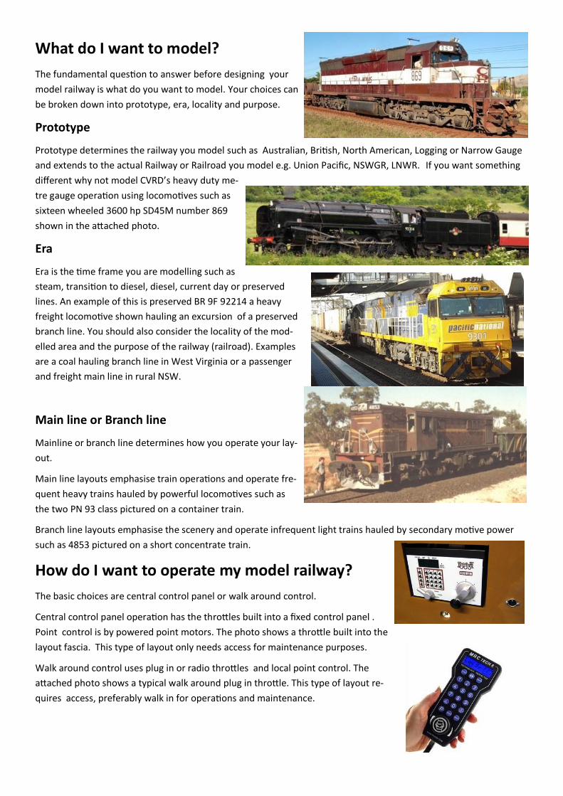
What do I want to model?
The fundamental question to answer before designing your
model railway is what do you want to model. Your choices can
be broken down into prototype, era, locality and purpose.
Prototype
Prototype determines the railway you model such as Australian, British, North American, Logging or Narrow Gauge
and extends to the actual Railway or Railroad you model e.g. Union Pacific, NSWGR, LNWR. If you want something
different why not model CVRD’s heavy duty me-
tre gauge operation using locomotives such as
sixteen wheeled 3600 hp SD45M number 869
shown in the attached photo.
Era
Era is the time frame you are modelling such as
steam, transition to diesel, diesel, current day or preserved
lines. An example of this is preserved BR 9F 92214 a heavy
freight locomotive shown hauling an excursion of a preserved
branch line. You should also consider the locality of the mod-
elled area and the purpose of the railway (railroad). Examples
are a coal hauling branch line in West Virginia or a passenger
and freight main line in rural NSW.
Main line or Branch line
Mainline or branch line determines how you operate your lay-
out.
Main line layouts emphasise train operations and operate fre-
quent heavy trains hauled by powerful locomotives such as
the two PN 93 class pictured on a container train.
Branch line layouts emphasise the scenery and operate infrequent light trains hauled by secondary motive power
such as 4853 pictured on a short concentrate train.
How do I want to operate my model railway?
The basic choices are central control panel or walk around control.
Central control panel operation has the throttles built into a fixed control panel .
Point control is by powered point motors. The photo shows a throttle built into the
layout fascia. This type of layout only needs access for maintenance purposes.
Walk around control uses plug in or radio throttles and local point control. The
attached photo shows a typical walk around plug in throttle. This type of layout re-
quires access, preferably walk in for operations and maintenance.

Practical considerations
Treating your first layout as a training/learning exercise is a sound idea. A modest sized
first layout allows you to decide what you do and don’t want on a future more extensive
layout. The following considerations can help you design a more enjoyable model railway.
Selective compression
It may seem attractive to model the entire Santa Fe but cost time and space
considerations make it impractical. Even modelling a specific location full size
becomes impractical.
Walong Loop in California where the track
rises 30 metres in a spiral loop is over 400
metres in diameter. Trains over one and
three quarter kilometres in length cross
over their tail rounding the loop. In HO
scale this is four and a half metres in diameter.
Our model railways are an impression of the railway we model. Selectively
compressing the scene you want to model allows you to model the essence of the locality in a manageable space.
The HO scale exhibition layout pictured based on Walong Loop set in winter measuring 1,200 mm by 1,800 mm
gave an impression of the location and the trains that run over it.
Deck height and accessibility
The height of your layout deck depends on the intended user. Access to your trains and track from the edge of
your layout is independent of the scale and gauge you use. For planning purposes we need to keep all track work
within reasonable reach from the edge of the layout.
A layout deck 1,000 mm high or lower allows you a reasonable reach from the layout edge of 750 mm. A 1,200
mm deck height allows you a reasonable reach from the layout edge of 600 mm.
Access ways
If you will be the only operator of your layout you can use 450 mm to 600 mm wide access ways and operating
areas.
If you intend to have regular operating sessions with a group of modellers you would be recommended to use
900 mm wide access ways and 1,200 mm wide operating areas in your layout design.
Layout size
While we’d all like a very large layout there are practical limitations to the size of your layout. Home layouts
larger than around 20 square metres in addition to the construction and equipment costs, require a lot of
maintenance to keep the track clean and the rolling stock in good condition. A 20 square metre layout would oc-
cupy a space three metres wide by six to seven metres long.
Basic research
Seeing other modellers layouts provides a wealth of track planning ideas. NMRA Australasian Region Divisions
meet monthly at members home layouts. Visiting these meetings as well as meeting local railway modellers will
let you see a variety of layout designs. Meeting locations and times are available from local divisional superinten-
dents. Superintendents contact details are listed on the Region web site nmra.org.au
Curve Radius and Point work
The most important layout planning decision you need to make is the curve radius
For railway modellers there are three classes of curve radius to consider
Prototype minimum
NMRA Recommended Practice RP 11
Manufacturers recommended minimum radius
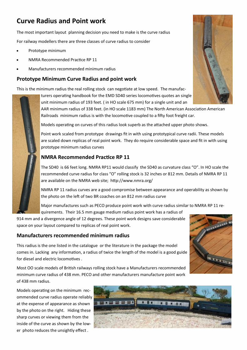
Prototype Minimum Curve Radius and point work
This is the minimum radius the real rolling stock can negotiate at low speed. The manufac-
turers operating handbook for the EMD SD40 series locomotives quotes an single
unit minimum radius of 193 feet. ( in HO scale 675 mm) for a single unit and an
AAR minimum radius of 338 feet. (in HO scale 1183 mm) The North American Association American
Railroads minimum radius is with the locomotive coupled to a fifty foot freight car.
Models operating on curves of this radius look superb as the attached upper photo shows.
Point work scaled from prototype drawings fit in with using prototypical curve radii. These models
are scaled down replicas of real point work. They do require considerable space and fit in with using
prototype minimum radius curves
NMRA Recommended Practice RP 11
The SD40 is 66 feet long. NMRA RP11 would classify the SD40 as curvature class “O”. In HO scale the
recommended curve radius for class “O” rolling stock is 32 inches or 812 mm. Details of NMRA RP 11
are available on the NMRA web site; http://www.nmra.org/
NMRA RP 11 radius curves are a good compromise between appearance and operability as shown by
the photo on the left of two BR coaches on an 812 mm radius curve
Major manufactures such as PECO produce point work with curve radius similar to NMRA RP 11 re-
quirements. Their 16.5 mm gauge medium radius point work has a radius of
914 mm and a divergence angle of 12 degrees. These point work designs save considerable
space on your layout compared to replicas of real point work.
Manufacturers recommended minimum radius
This radius is the one listed in the catalogue or the literature in the package the model
comes in. Lacking any information, a radius of twice the length of the model is a good guide
for diesel and electric locomotives .
Most OO scale models of British railways rolling stock have a Manufacturers recommended
minimum curve radius of 438 mm. PECO and other manufacturers manufacture point work
of 438 mm radius.
Models operating on the minimum rec-
ommended curve radius operate reliably
at the expense of appearance as shown
by the photo on the right. Hiding these
sharp curves or viewing them from the
inside of the curve as shown by the low-
er photo reduces the unsightly effect .
Train length, stations, passing tracks and staging tracks
The length of your trains has considerable effect on your track plan, particularly stations and staging tracks. Our
eyes perceive a train is long if it is longer than a 180 degree bend of your main line curves and consists of more
than seven vehicles.
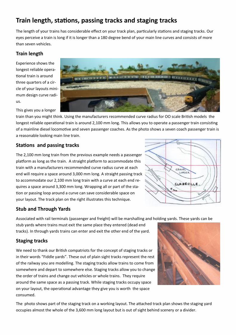
Train length
Experience shows the
longest reliable opera-
tional train is around
three quarters of a cir-
cle of your layouts mini-
mum design curve radi-
us.
This gives you a longer
train than you might think. Using the manufacturers recommended curve radius for OO scale British models the
longest reliable operational train is around 2,100 mm long. This allows you to operate a passenger train consisting
of a mainline diesel locomotive and seven passenger coaches. As the photo shows a seven coach passenger train is
a reasonable looking main line train.
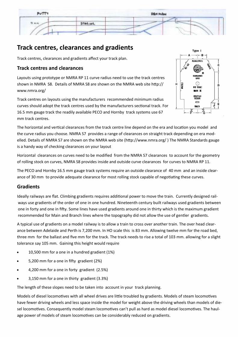
Stations and passing tracks
The 2,100 mm long train from the previous example needs a passenger
platform as long as the train. A straight platform to accommodate this
train with a manufacturers recommended curve radius curve at each
end will require a space around 3,000 mm long. A straight passing track
to accommodate our 2,100 mm long train with a curve at each end re-
quires a space around 3,300 mm long. Wrapping all or part of the sta-
tion or passing loop around a curve can save considerable space on
your layout. The track plan on the right illustrates this technique.
Stub and Through Yards
Associated with rail terminals (passenger and freight) will be marshalling and holding yards. These yards can be
stub yards where trains must exit the same place they entered (dead end
tracks). In through yards trains can enter and exit the other end of the yard.
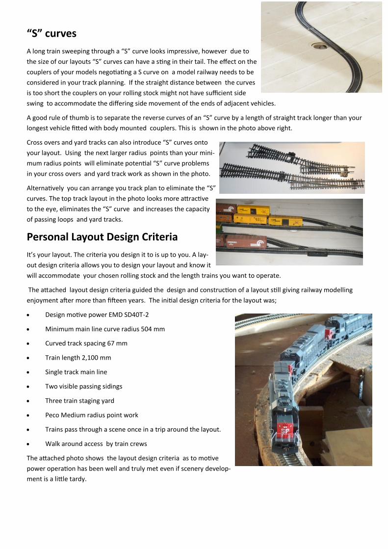
Staging tracks
We need to thank our British compatriots for the concept of staging tracks or
in their words “Fiddle yards”. These out of plain sight tracks represent the rest
of the railway you are modelling. The staging tracks allow trains to come from
somewhere and depart to somewhere else. Staging tracks allow you to change
the order of trains and change out vehicles or whole trains. They require
around the same space as a passing track. While staging tracks occupy space
on your layout, the operational advantage they give you is worth the space
consumed.
The photo shows part of the staging track on a working layout. The attached track plan shows the staging yard
occupies almost the whole of the 3,600 mm long layout but is out of sight behind scenery or a divider.
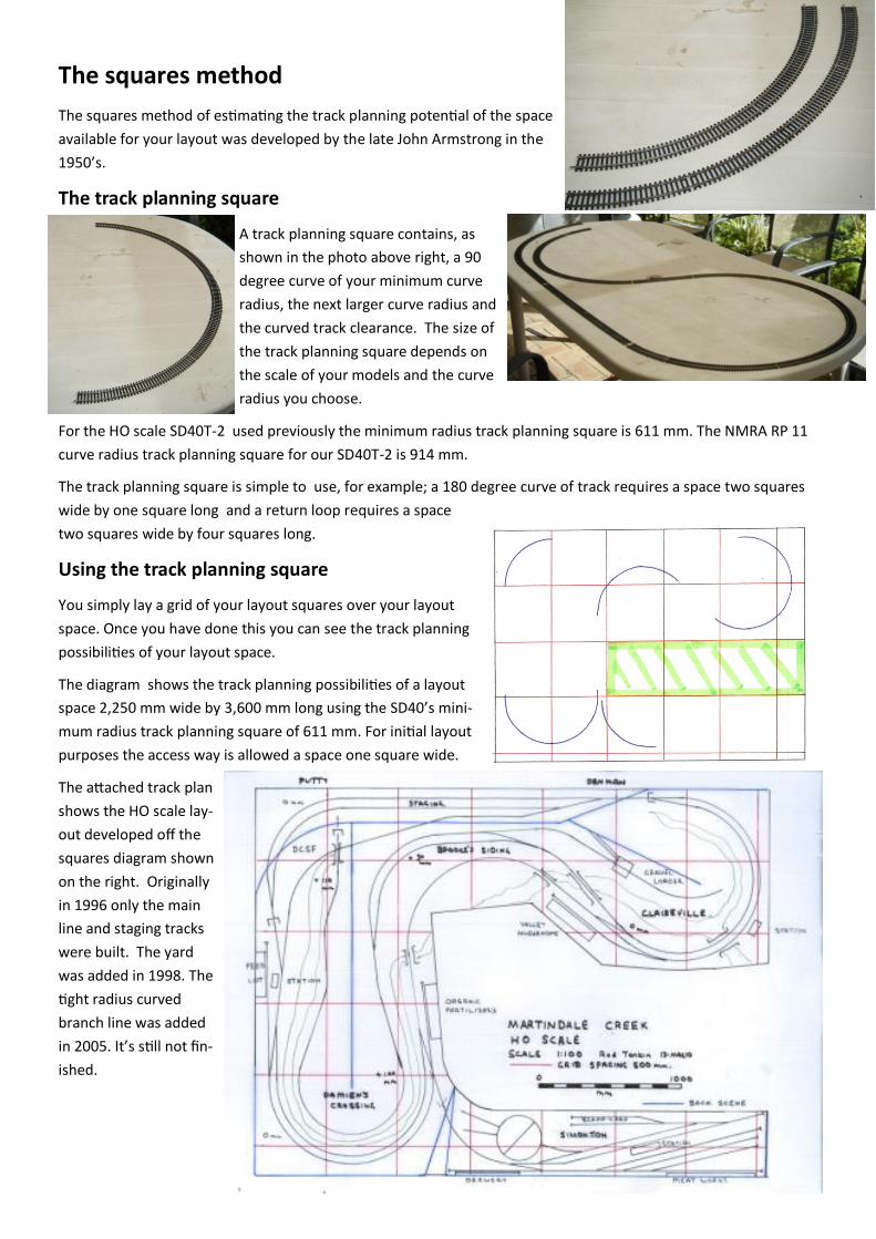
Track centres, clearances and gradients
Track centres, clearances and gradients affect your track plan.
Track centres and clearances
Layouts using prototype or NMRA RP 11 curve radius need to use the track centres
shown in NMRA S8. Details of NMRA S8 are shown on the NMRA web site http://
www.nmra.org/
Track centres on layouts using the manufacturers recommended minimum radius
curves should adopt the track centres used by the manufacturers sectional track. For
16.5 mm gauge track the readily available PECO and Hornby track systems use 67
mm track centres.
The horizontal and vertical clearances from the track centre line depend on the era and location you model and
the curve radius you choose. NMRA S7 provides a range of clearances on straight track depending on era mod-
elled. Details of NMRA S7 are shown on the NMRA web site (http://www.nmra.org/ ) The NMRA Standards gauge
is a handy way of checking clearances on your layout
Horizontal clearances on curves need to be modified from the NMRA S7 clearances to account for the geometry
of rolling stock on curves, NMRA S8 provides inside and outside curve clearances for curves to NMRA RP 11.
The PECO and Hornby 16.5 mm gauge track systems require an outside clearance of 40 mm and an inside clear-
ance of 30 mm to provide adequate clearance for most rolling stock capable of negotiating these curves.
Gradients
Ideally railways are flat. Climbing gradients requires additional power to move the train. Currently designed rail-
ways use gradients of the order of one in one hundred. Nineteenth century built railways used gradients between
one in forty and one in fifty. Some lines have used gradients around one in thirty which is the maximum gradient
recommended for Main and Branch lines where the topography did not allow the use of gentler gradients.
A typical use of gradients on a model railway is to allow a train to cross over another train. The over head clear-
ance between Adelaide and Perth is 7,200 mm. In HO scale this is 83 mm. Allowing twelve mm for the road bed,
three mm for the ballast and five mm for the track. The track needs to rise a total of 103 mm. allowing for a slight
tolerance say 105 mm. Gaining this height would require
10,500 mm for a one in a hundred gradient (1%)
5,200 mm for a one in fifty gradient (2%)
4,200 mm for a one in forty gradient (2.5%)
3,150 mm for a one in thirty gradient (3.3%)
The length of these slopes need to be taken into account in your track planning.
Models of diesel locomotives with all wheel drives are little troubled by gradients. Models of steam locomotives
have fewer driving wheels and less space inside the model for weight above the driving wheels than models of die-
sel locomotives. Consequently model steam locomotives can’t pull as hard as model diesel locomotives. The haul-
age power of models of steam locomotives can be considerably reduced on gradients.
“S” curves
A long train sweeping through a “S” curve looks impressive, however due to
the size of our layouts “S” curves can have a sting in their tail. The effect on the
couplers of your models negotiating a S curve on a model railway needs to be
considered in your track planning. If the straight distance between the curves
is too short the couplers on your rolling stock might not have sufficient side
swing to accommodate the differing side movement of the ends of adjacent vehicles.
A good rule of thumb is to separate the reverse curves of an “S” curve by a length of straight track longer than your
longest vehicle fitted with body mounted couplers. This is shown in the photo above right.
Cross overs and yard tracks can also introduce “S” curves onto
your layout. Using the next larger radius points than your mini-
mum radius points will eliminate potential “S” curve problems
in your cross overs and yard track work as shown in the photo.
Alternatively you can arrange you track plan to eliminate the “S”
curves. The top track layout in the photo looks more attractive
to the eye, eliminates the “S” curve and increases the capacity
of passing loops and yard tracks.
Personal Layout Design Criteria
It’s your layout. The criteria you design it to is up to you. A lay-
out design criteria allows you to design your layout and know it
will accommodate your chosen rolling stock and the length trains you want to operate.
The attached layout design criteria guided the design and construction of a layout still giving railway modelling
enjoyment after more than fifteen years. The initial design criteria for the layout was;
Design motive power EMD SD40T-2
Minimum main line curve radius 504 mm
Curved track spacing 67 mm
Train length 2,100 mm
Single track main line
Two visible passing sidings
Three train staging yard
Peco Medium radius point work
Trains pass through a scene once in a trip around the layout.
Walk around access by train crews
The attached photo shows the layout design criteria as to motive
power operation has been well and truly met even if scenery develop-
ment is a little tardy.
The squares method
The squares method of estimating the track planning potential of the space
available for your layout was developed by the late John Armstrong in the
1950’s.
The track planning square
A track planning square contains, as
shown in the photo above right, a 90
degree curve of your minimum curve
radius, the next larger curve radius and
the curved track clearance. The size of
the track planning square depends on
the scale of your models and the curve
radius you choose.
For the HO scale SD40T-2 used previously the minimum radius track planning square is 611 mm. The NMRA RP 11
curve radius track planning square for our SD40T-2 is 914 mm.
The track planning square is simple to use, for example; a 180 degree curve of track requires a space two squares
wide by one square long and a return loop requires a space
two squares wide by four squares long.
Using the track planning square
You simply lay a grid of your layout squares over your layout
space. Once you have done this you can see the track planning
possibilities of your layout space.
The diagram shows the track planning possibilities of a layout
space 2,250 mm wide by 3,600 mm long using the SD40’s mini-
mum radius track planning square of 611 mm. For initial layout
purposes the access way is allowed a space one square wide.
The attached track plan
shows the HO scale lay-
out developed off the
squares diagram shown
on the right. Originally
in 1996 only the main
line and staging tracks
were built. The yard
was added in 1998. The
tight radius curved
branch line was added
in 2005. It’s still not fin-
ished.
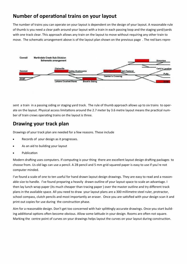
Number of operational trains on your layout
The number of trains you can operate on your layout is dependent on the design of your layout. A reasonable rule
of thumb is you need a clear path around your layout with a train in each passing loop and the staging yard/yards
with one track clear. This approach allows any train on the layout to move without requiring any other train to
move. The schematic arrangement above is of the layout plan shown on the previous page . The red bars repre-
sent a train in a passing siding or staging yard track. The rule of thumb approach allows up to six trains to oper-
ate on the layout. Physical access limitations around the 2.7 meter by 3.6 metre layout means the practical num-
ber of train crews operating trains on the layout is three.
Drawing your track plan
Drawings of your track plan are needed for a few reasons. These include
Records of your design as it progresses.
As an aid to building your layout
Publication
Modern drafting uses computers. If computing is your thing there are excellent layout design drafting packages to
choose from. Us old lags can use a pencil. A 2B pencil and 5 mm grid squared paper is easy to use if you’re not
computer minded.
I’ve found a scale of one to ten useful for hand drawn layout design drawings. They are easy to read and a reason-
able size to handle. I’ve found preparing a heavily drawn outline of your layout space to scale an advantage. I
then lay lunch wrap paper (its much cheaper than tracing paper ) over the master outline and try different track
plans in the available space. All you need to draw your layout plans are a 300 millimetre steel ruler, protractor,
school compass, clutch pencils and most importantly an eraser. Once you are satisfied with your design scan it and
print out copies for use during the construction phase.
Aim for a reasonable design. Don’t get too concerned with hair splittingly accurate drawings. Once you start build-
ing additional options often become obvious. Allow some latitude in your design. Rooms are often not square.
Marking the centre point of curves on your drawings helps layout the curves on your layout during construction.
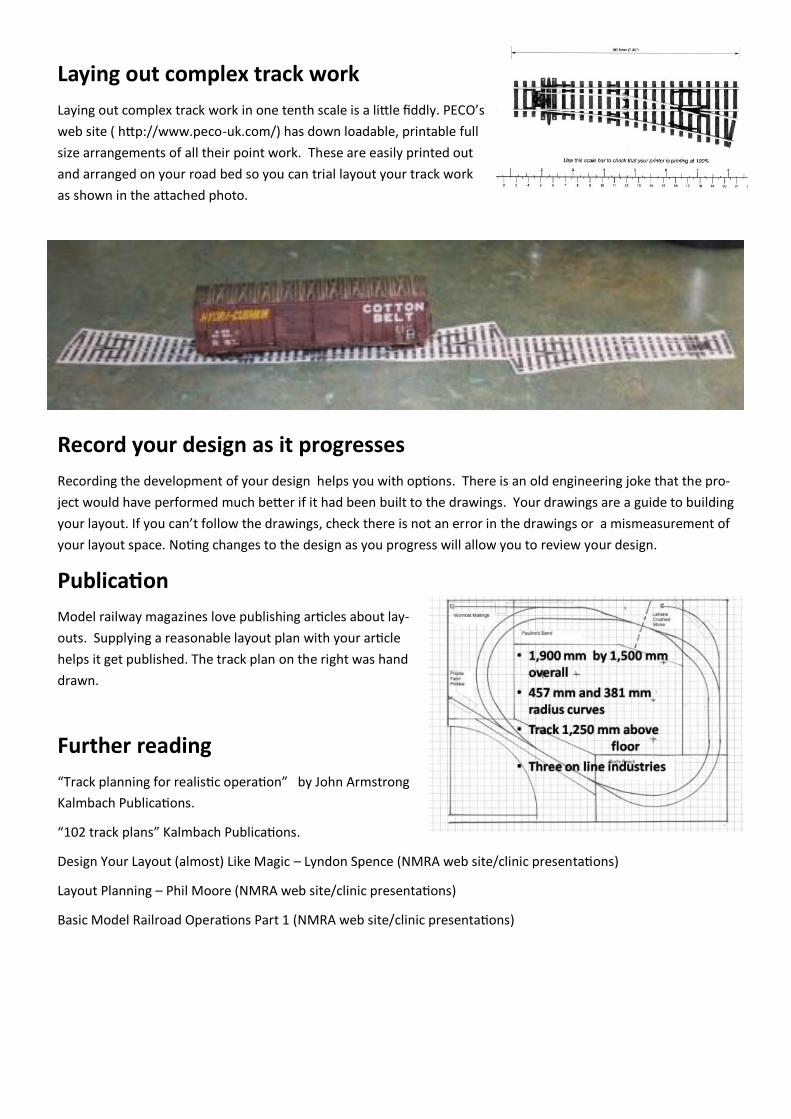
Laying out complex track work
Laying out complex track work in one tenth scale is a little fiddly. PECO’s
web site ( http://www.peco-uk.com/) has down loadable, printable full
size arrangements of all their point work. These are easily printed out
and arranged on your road bed so you can trial layout your track work
as shown in the attached photo.
Record your design as it progresses
Recording the development of your design helps you with options. There is an old engineering joke that the pro-
ject would have performed much better if it had been built to the drawings. Your drawings are a guide to building
your layout. If you can’t follow the drawings, check there is not an error in the drawings or a mismeasurement of
your layout space. Noting changes to the design as you progress will allow you to review your design.
Publication
Model railway magazines love publishing articles about lay-
outs. Supplying a reasonable layout plan with your article
helps it get published. The track plan on the right was hand
drawn.
Further reading
“Track planning for realistic operation” by John Armstrong
Kalmbach Publications.
“102 track plans” Kalmbach Publications.
Design Your Layout (almost) Like Magic – Lyndon Spence (NMRA web site/clinic presentations)
Layout Planning – Phil Moore (NMRA web site/clinic presentations)
Basic Model Railroad Operations Part 1 (NMRA web site/clinic presentations)