
Education - K'Nexmedia.knex.com/instructions/instruction-books/Education...4 Resistance: The force...
41
78620 78620 TEACHER’S GUIDE WHEEL & AXLES AND INCLINED PLANES INTRODUCTION TO SIMPLE MACHINES Education ®
Transcript of Education - K'Nexmedia.knex.com/instructions/instruction-books/Education...4 Resistance: The force...

7862078620
TEACHER’SGUIDE
WHEEL & AXLES AND INCLINED PLANES
INTRODUCTION TO SIMPLE MACHINES
Education®

WHEELS & AXLES AND INCLINED PLANESTeacher’s Guide
V3-8/14©2014 K’NEX Limited Partnership Group and its licensors.
K’NEX Limited Partnership GroupP.O. Box 700Hatfield, PA 19440-0700
K’NEX Education is a registered trademark of K’NEX Limited Partnership Group.Protected by International Copyright. All rights reserved.
Visit our website at www.knexeducation.comEmail: [email protected]: 1-888-ABC-KNEX (Toll Free)
A NOTE ABOUT SAFETY:Safety is of primary concern in science and technology classrooms. It is recommended that you develop a set of rules that governs the safe, proper use of K’NEX in your classroom. Safety, as it relates to the use of the Rubber Bands should be specifically addressed.
CAUTIONS:Students should not overstretch or overwind their Rubber Bands. Overstretching and overwinding can cause the Rubber Band to snap and cause personal injury. Any wear and tear or deterioration of Rubber Bands should be reported immediately to the teacher. Teachers and students should inspect Rubber Bands for deterioration before each experiment.
Caution students to keep hands and hair away from all moving parts. Never put fingers in moving Gears or other moving parts.
INTRODUCTION�TO�SIMPLE�MACHINES
WHEELS & AXLES AND INCLINED PLANES Education®
WARNING:CHOKING HAZARD – Small parts. Not for children under 3 years.
ATTENTION :RISQUE D’ÉTOUFFEMENT – Pièces de petite taille. Ne convient pas aux enfants de moins de 3 ans.
Introduction:
1
OVERVIEWThis Teacher’s Guide has been developed to support you as your students investigate the K’NEX Intro to Simple Machines: Wheels & Axles and Inclined Planes set. In conjunction with the K’NEX materials and individual student journals, the information and resources included here can be used to build your students’ understanding of scientific concepts and channel their inquiries into active and meaningful learning experiences.
K’NEX INTRO TO SIMPLE MACHINES: Wheels & Axles and Inclined Planes. Part of a series, this K’NEX construction set is designed to introduce students to the scientific concepts associated with two types of Simple Machines - wheels and axles, and inclined planes. Students are provided with the opportunity to acquire skills using a hands-on, inquiry-based approach to information and concepts. Working cooperatively, students are encouraged to interact with each other as they build, investigate, discuss, and evaluate scientific principles in action.
TEACHER’S GUIDE. Designed as a resource for the teacher, this guide provides a glossary of key terms and definitions, includes an overview of the concepts associated with wheels and axles, and inclined planes, identifies student objectives for each unit, and offers plans and scripts to successfully present each simple machine model and its associated activities. Most of the units can be completed in 30-45 minutes. There are also extension activities that can be used to explore the concepts more deeply. We recommend that teachers review their curriculum and standards to identify which of the activities provided in this guide best meet their needs.
STUDENT JOURNALS. It is expected that student will always have journals available for recording information. They should be encouraged to enter initial thoughts at the start of an inquiry - what they “think” will happen. These initial thoughts may be amended, based on their ongoing inquiry and analysis, until the students feel comfortable about drawing conclusions. Their journal entries will help make a connection between the models they have built, the experiments they have conducted, and how this information is applied to the real-world machines they use on a regular basis. The journals will also provide students with a place to practice making drawings and diagrams of systems. Finally, the journals will serve as a method of assessment for the Simple Machines unit. Journal Checklists are included in the Teacher’s Guide for each of the models and their associated inquiry activities.
TABLE OF CONTENTS
Wheels and Axles .................................................................................................................................... 3-22
Objectives ............................................................................................................................................................... 3
Key Terms & Definitions .................................................................................................................................... 3-4
Key Concepts ....................................................................................................................................................... 4-6
The Well ............................................................................................................................................................ 7-13
The Paddle Boat .............................................................................................................................................. 14-18
The Steering Wheel ......................................................................................................................................... 19-22
Inclined Planes ..................................................................................................................................... 23-39
Objectives ............................................................................................................................................................. 23
Key Terms & Definitions ................................................................................................................................ 23-24
Key Concepts ................................................................................................................................................... 24-25
Steep and Long Ramps ................................................................................................................................... 26-30
The Splitting Wedge ........................................................................................................................................ 31-34
The Hand Drill ................................................................................................................................................. 35-39
INTRODUCTION�TO�SIMPLE�MACHINES
www.knexeducat ion.com Education®
2
Wheels & AxlesWheels & AxlesBackground Information
3
KEY TERMS and DEFINITIONS for the teacher. The following is intended as a glossary for the teacher. The age of the students, their abilities, their prior knowledge, and the curriculum requirements will determine which of these terms and definitions you introduce into your classroom activities.
Simple Machine: A simple tool that makes work easier to do. Most simple machines have only one moving part. Simple machines make work easier by changing the way in which the work is done. They do not change the amount of work that is needed to do the job.
Wheel and Axle: A round disk (wheel) with a rod (axle) rigidly attached through its center so that when one turns, so does the other. It is used to transfer force. Some examples actually look like a wheel with an axle, but others have a wheel that resembles a handle, such as that on a fishing reel, or a knob, such as a doorknob or the volume knob on a radio. All wheel and axle mechanisms behave like a lever rotating around a fixed point.
Force: Any kind of push or pull applied to an object.
Work: The task being completed while using a wheel and axle. In science, work refers to the use of force to move a load (object) through a distance. It can be defined as follows:
W = F x D
Where W = work
F = the force (effort) applied to the task
D = the distance through which the force is applied
NOTE: If the object has not moved, work has not been done.
Effort:The force that is applied to move one component of a simple machine (ie: the force that is applied to do work). The force applied to a simple machine is called the effort force. If a wheel is turning an axle, the effort force is a measure of the force that is applied to the wheel over the distance that the wheel moves. The machine then transfers the force to the axle, which moves the load.
OBJECTIVESStudents will:1. Study the characteristics of the wheel and axle system to understand how it works.
2. Describe the relationships between the parts of a wheel and axle system.
3. Construct different types of wheel and axle systems and demonstrate how they function.
4. Identify whether the wheel turns the axle, or whether the axle turns the wheel, and determine how this affects the way the system works.
5. Identify how the use of a wheel and axle system affects work in relation to force, distance, speed and direction.
6. Understand how the size of the wheel and axle affects the work performed.
7. Analyze objects/tools in terms of their application as wheel and axle systems.
INTRODUCTION�TO�SIMPLE�MACHINES
www.knexeducat ion.com Education®

4
Resistance: The force exerted by the object (load) upon which one is trying to do work; it works against the effort.
Load: The object (weight) moved or the resistance that is overcome when using a wheel and axle. It exerts a force (resistance) against the wheel and axle.
Friction: The force caused when 2 surfaces rub together as an object moves.
Mechanical Advantage (MA): A mathematical calculation that indicates how many times the simple machine multiplies the effort force. For a wheel and axle system it can be calculated using the following formula:
Effort radius (ER)
Resistance radius (RR)
Where ER = the radius of the wheel or axle supplying effort
RR = the radius of the wheel or axle not supplying effort
Mechanical Advantage is always expressed as a number without a unit. EG: MA = 2
KEY CONCEPTSTo move a load using a wheel and axle mechanism, the effort force is applied EITHER to turn the wheel OR to turn the axle.
A wheel and axle mechanism behaves as if it is a rotating lever with the center of the axle as the fulcrum and the wheel rim as the outer edge of the lever. With levers, the further the effort is from the fulcrum, the less effort is needed to move a load. The same is true for the wheel and axle. The larger wheel requires less effort to move a load when compared to a smaller wheel like the axle.
A wheel and axle system makes work easier by making things easier to move. It can do this in the following ways:
Increasing the force that is applied to do a job. Because the wheel and axle act like a rotating lever, when the wheel turns, its rim will move a greater distance than the axle, but it needs less effort to turn it. The axle, meanwhile, turning through a small distance, gains in force what is lost in the distance moved. The force is increased due to the difference in size between the wheel and the axle.
= MA
RR
ER
RR
ER
Wheel provides the effort
Axle provides the effort
INTRODUCTION�TO�SIMPLE�MACHINES
WHEELS & AXLES AND INCLINED PLANESEducation®
Wheels & Axles
5
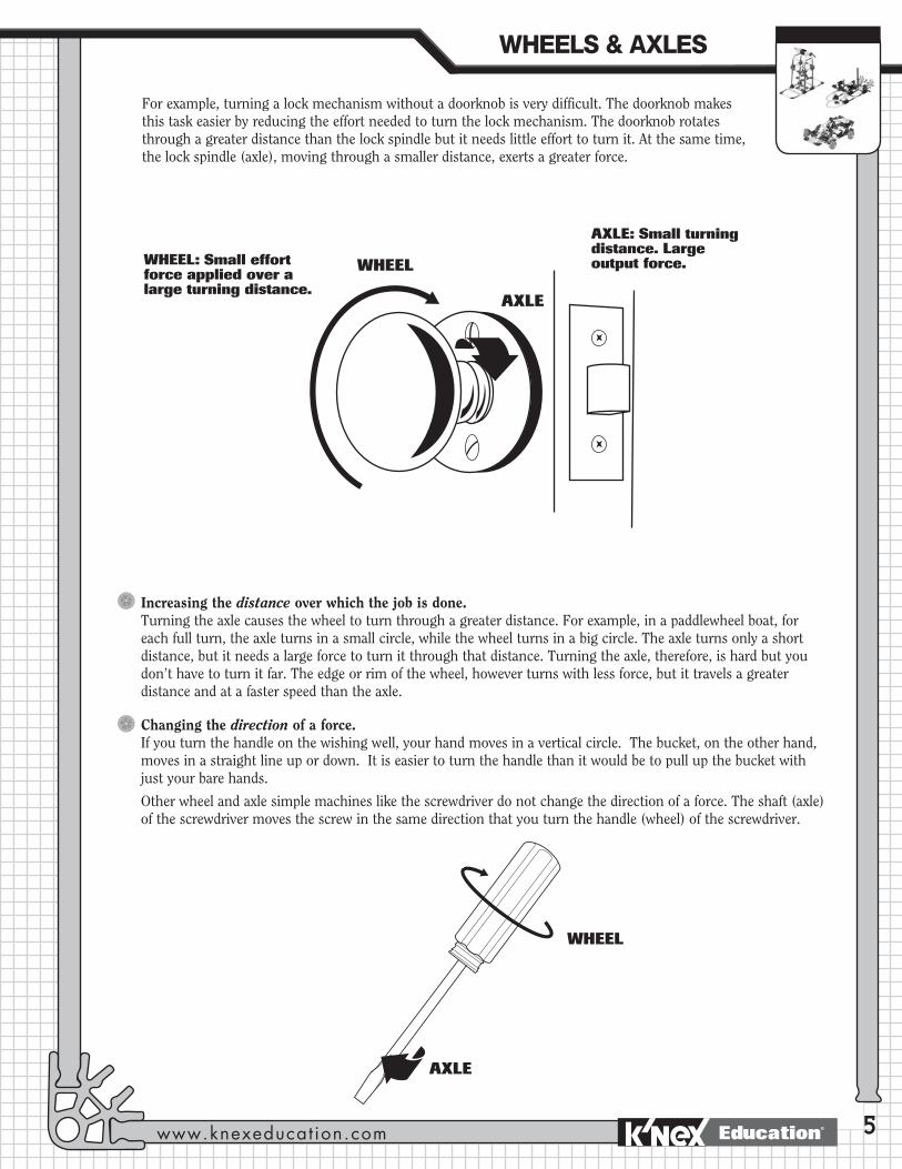
For example, turning a lock mechanism without a doorknob is very difficult. The doorknob makes this task easier by reducing the effort needed to turn the lock mechanism. The doorknob rotates through a greater distance than the lock spindle but it needs little effort to turn it. At the same time, the lock spindle (axle), moving through a smaller distance, exerts a greater force.
AXLEAXLE
AXLE:AXLE
AXLE: Small turning distance. Large output force.WHEELWHEEL
WHEELWHEEL
WHEEL: Small effort force applied over a large turning distance.
Increasing the distance over which the job is done.Turning the axle causes the wheel to turn through a greater distance. For example, in a paddlewheel boat, for each full turn, the axle turns in a small circle, while the wheel turns in a big circle. The axle turns only a short distance, but it needs a large force to turn it through that distance. Turning the axle, therefore, is hard but you don’t have to turn it far. The edge or rim of the wheel, however turns with less force, but it travels a greater distance and at a faster speed than the axle.
Changing the direction of a force. If you turn the handle on the wishing well, your hand moves in a vertical circle. The bucket, on the other hand, moves in a straight line up or down. It is easier to turn the handle than it would be to pull up the bucket with just your bare hands.
Other wheel and axle simple machines like the screwdriver do not change the direction of a force. The shaft (axle) of the screwdriver moves the screw in the same direction that you turn the handle (wheel) of the screwdriver.
WHEELS�&�AXLES
www.knexeducat ion.com Education®

6
NOTE: Some of the wheel and axle systems used on vehicles are different from other wheel and axle simple machines. These have wheels that are NOT fixed to their axles and the wheels simply make moving across a surface easier by reducing the friction. These wheels and axles on a vehicle do not offer a Mechanical Advantage.
As previously noted, simple machines make work easier. They do this by either multiplying the force applied or increasing the distance (rate) the resistance moves. This is because force and distance cannot both increase at the same time. When one increases, the other must decrease since work output is never greater than work input.
ADDITIONAL EVERYDAY EXAMPLES OF WHEELS and AXLES.FAUCET: The handle of the faucet is the wheel. When the handle is turned, using a small effort force, it rotates through a large circular distance. The axle, with its smaller circumference, rotates through a smaller distance with greater force. This then operates the valve in the faucet to allow the water to flow.
SCREWDRIVER: The handle of the screwdriver is the wheel; the shaft is the axle. The screwdriver’s thicker handle and thinner metal shaft rotate together to turn a screw. When effort force is applied to the handle (wheel) of the screwdriver it rotates through a greater distance than the shaft (axle) but this force is multiplied as the shaft rotates through its smaller turning circle and allows the screw to be easily inserted. Turning a large wheel is easier than turning a small axle so the work is made easier. This concept can be demonstrated by attempting to unscrew a screw by turning the metal shaft (axle) of the screwdriver. It will be much harder to do the job this way, compared to turning the screwdriver by its larger handle (wheel).
WHEEL
AXLE
INTRODUCTION�TO�SIMPLE�MACHINES
WHEELS & AXLES AND INCLINED PLANESEducation®
Wheels & AxlesThe Well:
An example of a wheel turning an axle.
The Well
7
PROCEDUREIntroduction
If this is their first introduction to simple machines you may want to demonstrate the concept of work by having 3 or 4 students pushing as hard as they can against a wall in the classroom for 1 minute. Then ask another group of 3 or 4 students to each push a book across his or her desk. Ask the rest of the class to decide who was doing ‘work.’
Following this, provide the students with background information on the concepts of work, force, effort, resistance, and load (See Key Terms and Key Concepts on Page 3 of this Guide.) Ask them to then identify where the effort force came from and what represented the load or resistance for both activities.
Ask them if the wall or the books moved. Explain that although the group pushing against the wall exerted a great deal of energy or force, the wall itself didn’t move so, from a scientific point of view, no work was done. The group pushing the books, however, did do work. Students should record their observations in their journals.
OBJECTIVESStudents will:1. Understand the scientific concept of work and the idea that simple machines can
make work easier.
2. Demonstrate the characteristics of a wheel and axle.
3. Investigate how a wheel turning an axle makes work easier.
4. Explore how varying the size of the wheel will affect the amount of effort needed to do a job.
MATERIALSEach group of 2 students will need: - 1 K’NEX Wheels & Axles and
Inclined Planes Building Set with building instructions booklet
- Marker
- Paper cup
- Pennies or small paper clips
- Yardstick (Meterstick)
- Student Journals
- 200 gram or 5 Newton spring scale (optional)
You will need:Pictures and examples of different kinds of wheels and axles. (Suggestions: plastic thread spool with a pencil inserted into its center hole; doorknob; screwdriver.)
WHEELS�&�AXLES
www.knexeducat ion.com Education®

8
Begin the lesson by defining a wheel and axle. (A definition is provided on Page 3 of this Guide.) Refer to the fact that a wheel and axle is a simple machine. Have an example available, constructed from a thread spool and pencil, to demonstrate the parts. Draw a labeled diagram on the board (See diagram below.)
Ask the students to provide examples of the use of wheels and axles in their daily lives. They will probably describe the wheels and axles on a car or bus. This will give you the opportunity to explain how these differ from other wheel and axle simple machines, in that the wheel moves independently from the axle and the function of the wheel, in this case, is simply to reduce friction. Probe for the less obvious examples, such as faucets, doorknobs and screwdrivers.
Ask the group to think of ways in which our lives would be different without the use of this simple machine. Encourage them to consider the ways in which wheels and axles make our work easier every day. Ask them to suggest alternatives to doorknobs and screwdrivers. Suggest that they explore these options at home.
Suggest that they search the Internet for additional information about wheels and axles. (Recommend that they enter the key words: Simple Machines into a search engine such as Google.)
Organize the class into teams of 2 (maximum 3) students and distribute yardsticks.
Inquiry ActivityWe would like to thank Susan Frazier and the directors of the SMILE program at the Illinois Institute of Technology for granting us their permission to include the following activity. ©1990. [Please visit http://www.iit.edu/~smile/ph9005.html for further information.]
Explain that each team will first explore the characteristics of a wheel and axle by simulating one using their arms and a yardstick.
Ask one member of each team (A) to grasp the yardstick in the middle and hold it out in front of them. Student B then places a hand on either side of Student A’s hand and tries to turn the stick while Student A attempts to prevent it turning. Student B should repeatedly move his/her hands further apart until the stick turns easily. (See diagram on next page.)
Ask the students what they think Student A’s hand represented (axle) and what the yardstick represented (wheel.)
Ask them to record the experiment in their journals together with a labeled diagram.
AXLE
WHEEL
INTRODUCTION�TO�SIMPLE�MACHINES
WHEELS & AXLES AND INCLINED PLANESEducation®

Wheels & Axles The Well
9
Building ActivityDistribute a K’NEX Wheels & Axles and Inclined Planes building set to each group. Ask them to open up the materials and locate the building instructions booklet. If the class has not used K’NEX building materials before, draw their attention to the building tips page. It is crucial that the students grasp the building concept at this stage so that frustrations are avoided later.
Provide some basic guidelines for maintaining all the pieces in the set for future use.
Remind them that they will need about 5 minutes at the end of the class period for cleaning up the materials.
Explain that they will build a model of a well that incorporates a wheel and axle system. They will then use the model to investigate how a wheel and axle can help them do work.
Invite the students to build the WELL model (Pages 2-3 of the building instructions booklet.) We recommend that one student build Steps 1-3 and the other, Steps 4-7. The parts should then be assembled, as shown, to form the completed well.
Inquiry Activity: How does the wheel and axle help you do work?Provide each group with a paper cup filled with pennies or paper clips and ask them to feel its weight and then place the cup into the bucket of the well model. Use the following script to help the students explore the function of the wheel and axle.
Steps
1. Move two desks close enough together so that you can place one side of the well’s base on one desk edge and the other side on a second desk edge. Put a book on each side to hold the model firmly in place. Lower the bucket to the floor. (See Page 3 of the building instructions booklet.)
WHEELS�&�AXLES
www.knexeducat ion.com Education®

10
Ask the class to investigate the well by first locating the wheel and axle in the machine. (The rod across the top is the axle. The crank, which turns in a circle, is the wheel.)
The students should record in their journals the difference in the sizes of circumference of the wheel and axle. They should note which travels the further with one rotation. (The wheel.)
Ask the following questions:
(a) Do you turn the wheel to make the axle go round? If so, the machine helps you complete the task by multiplying the force you apply.
(b) Or, do you turn the axle to make the wheel go round? If so, your machine helps you cover more distance at a faster speed.
(c) Ask the students to determine exactly how the well works.
The large wheel turns through a long distance with a small amount of effort force, while the small axle turns through a small distance, but with greater force.
The small axle turns through a small distance using a large amount of effort, while the large wheel rotates through a large distance with a small amount of effort.
Students should discover that they turn the wheel to make the axle rotate.
When you provide effort by turning the crank, the rod turns, winding up a rope to raise the bucket, which is the resistance or load. This simple machine makes lifting the bucket much easier than just hauling on the rope by hand.
Wheel(Crank)Small Axle
INTRODUCTION�TO�SIMPLE�MACHINES
WHEELS & AXLES AND INCLINED PLANESEducation®

Wheels & Axles The Well
1 1
2. (a) Start with the blue rod facing up and turn the wheel all the way around to lift the bucket. Be careful not to let go of the rod as you turn, or the string will quickly unwind and the bucket will drop.
(b) Count the number turns it takes to raise the bucket from the floor to the top of the desk. Each time the blue rod faces up it has completed one turn. Record this number.
(c) How far does the bucket move each time you turn the wheel (crank)?
(d) How could a wheel and axle in a real well make it easier for you to lift a filled bucket?
3. (a) Remove the yellow rods from the axle and attach the string to the red rod that now forms the axle. (See Small Axle picture on Page 3 of the building instructions booklet.)
(b) Lower the bucket to the floor again.
(c) Count the number of turns it takes to raise the bucket from the floor to the top of the desk. Record this number.
(d) What do you notice as you turn the wheel to lift the bucket?
(e) Compare the number of turns to raise the bucket for the two axles?
(f) Which axle was easier to turn?
(g) Why?
-
Depending on the height of their desks, it should take about 5-7 turns of the crank to lift the bucket to the desktop. For each full rotation of the wheel, the bucket moves the same distance as the circumference of the axle. Students should realize that it would be easier to turn the wheel of a real well than it would be to haul the bucket up on a rope.
Again, depending on the desk height, it should take about 20-22 rotations to raise the bucket to the desktop. Students should notice that it takes many more turns to lift the bucket using the small axle than the big axle. Students will find that the small axle made it easier to lift the bucket because they had to apply less effort to turn the wheel with the small axle than with the big axle. However, they have to turn the wheel more times. Using a wheel to turn a small axle is easier than using the same size wheel to turn a larger axle.
Class IdeaSet up the building activity so that one half of the class makes the model with the yellow rods for the axle and the other half makes it with the single red rod. Then ask the students to move from one model to the other to discover which type of axle requires the most effort to raise the bucket.
Small Axle
Big Axle
WHEELS�&�AXLES
www.knexeducat ion.com Education®

12
4. (a) Change the size of the wheel by using longer and shorter rods and then repeat the experiment.
(b) How do the other rods compare with the blue rod?
(c) Do they make it easier or harder to lift the bucket?
(d) What does this tell you about how the size of the wheel affects your work?
Applying The Idea
Ask the students to write about the advantages and disadvantages of both axles and the different size wheels in their journals.
Encourage them to discuss situations where the different sizes would be appropriate.
Ask the students to decide which combination of wheel and axle will make it easiest to lift the bucket.
Ask the students to build and test other sizes of wheels and axles to validate their findings.
Students should notice that using longer rods for the wheel will make it easier to turn the axle. Shorter rods will make it harder to turn the axle. If your class has already explored levers you can explain that a wheel and axle works as a lever that rotates and tie in their knowledge about how the length of the lever arm affects the work carried out.
The small axle is easier to turn but it requires more turns to lift an object. The big axle takes fewer turns but it needs more effort to turn it. The bigger the wheel, the easier it is to turn the axle but you have to turn it through a greater distance.
You may use a small axle in a situation where you need to lift something heavy and you want the wheel to turn easily. You may use a big axle if you want to lift something quickly that is not very heavy.
The largest wheel and the smallest axle.
Extending The Idea1. (a) Use a spring scale to measure the effort force you applied to lift the cup in the different situations in the
activity. Attach the scale to the cup to measure the effort force required to lift it without the well’s wheel and axle mechanism.
(b) Snap a gray connector to the end of the blue rod that forms the crank (handle) of the well. Hook the spring scale onto the gray connector. Pull the spring scale straight up to lift the handle in each of the different situations in the activity.
(c) Record and compare readings. Use them to determine which wheel and axle system requires the least, and which requires the most, effort. Explain your answers.
(d) Calculate the work done by this simple machine. This can be calculated using the following formula:
Output Work = Weight of the bucket x Distance it moves.
INTRODUCTION�TO�SIMPLE�MACHINES
WHEELS & AXLES AND INCLINED PLANESEducation®
Wheels & Axles The Well
13
2. Ask the students to calculate the Mechanical Advantage of the wheel and axle combinations they have built. Use the following directions:
(a) Measure the diameter of the wheel or the axle – whichever one provided the effort. Then divide the diameter in half to get the effort radius (ER).
(b) Measure the diameter of the wheel or axle – whichever one isn’t providing the effort. Then divide this diameter in half to get the resistance radius (RR).
(c) Divide the ER by the RR to find the Mechanical Advantage (MA).
ER ÷ RR = MAIn the example of the well, where the wheel turns the axle, the MA = Radius of Wheel ÷ Radius of Axle. The calculation will result in a Mechanical Advantage of more than 1, indicating that the simple machine makes work easier by multiplying the force.
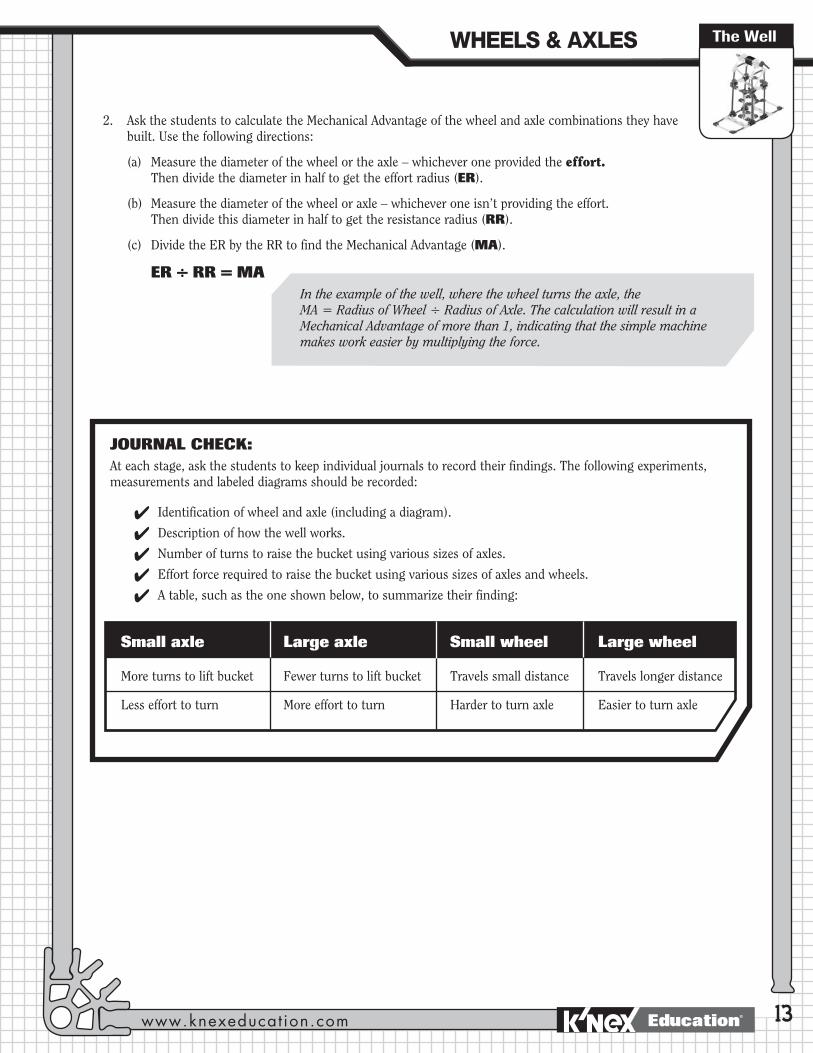
JOURNAL CHECK: At each stage, ask the students to keep individual journals to record their findings. The following experiments, measurements and labeled diagrams should be recorded:
4 Identification of wheel and axle (including a diagram).
4 Description of how the well works.
4 Number of turns to raise the bucket using various sizes of axles.
4 Effort force required to raise the bucket using various sizes of axles and wheels.
4 A table, such as the one shown below, to summarize their finding:
Small axle Large axle Small wheel Large wheel
More turns to lift bucket Fewer turns to lift bucket Travels small distance Travels longer distance
Less effort to turn More effort to turn Harder to turn axle Easier to turn axle
WHEELS�&�AXLES
www.knexeducat ion.com Education®

14

Wheels & AxlesThe Paddleboat: An example of an axle turning a wheel.
The Paddleboat
15
OBJECTIVESStudents will:1. Discover how an axle, turning a wheel, increases the distance and speed at which
an object travels.
2. Investigate how increasing the size of a wheel increases the distance it travels with each rotation.
MATERIALSEach group of 2 students will need: - 1 K’NEX Wheels & Axles and
Inclined Planes Building Set with building instructions booklet
- 2 small blocks of wood or Styrofoam
- Student Journals
- Heavy duty rubber bands
- Access to a large tub or sink
An engine turns an axle, which then turns the large wheel(s).
PROCEDUREIntroduction
Review how the WELL uses a wheel to turn an axle to increase (multiply) force and make the work of raising a heavy object easier.
Explain that the students will now explore a different use of a wheel and axle. The students will build a paddleboat and discover how the wheel and axle helps make the work of moving a boat through the water easier. Refer the class to the photo of the paddleboat on Page 4 of the building instructions booklet.
Ask the class to think of places where paddleboats are found today. Ask if anyone knows (or believes they know) how such boats operate.
WHEELS�&�AXLES
www.knexeducat ion.com Education®
16
Building ActivityDistribute a K’NEX Wheels & Axles and Inclined Planes building set to each group.
(NOTE: Ensure that the students understand that over-extending the rubber band in the set can result in a snap back or loss of control; they need to be very careful. See Safety Information at the beginning of the Guide.)
Ask them to turn to Page 4 of the building instructions booklet and construct the model of a PADDLEBOAT. One student should build Steps 1 – 5 and the other, Steps 6 – 8 and then the two parts should be assembled to form the complete boat.
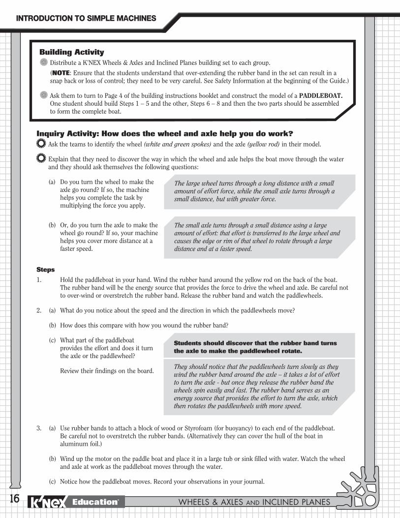
Inquiry Activity: How does the wheel and axle help you do work?Ask the teams to identify the wheel (white and green spokes) and the axle (yellow rod) in their model.
Explain that they need to discover the way in which the wheel and axle helps the boat move through the water and they should ask themselves the following questions:
(a) Do you turn the wheel to make the axle go round? If so, the machine helps you complete the task by multiplying the force you apply.
(b) Or, do you turn the axle to make the wheel go round? If so, your machine helps you cover more distance at a faster speed.
Steps
1. Hold the paddleboat in your hand. Wind the rubber band around the yellow rod on the back of the boat. The rubber band will be the energy source that provides the force to drive the wheel and axle. Be careful not to over-wind or overstretch the rubber band. Release the rubber band and watch the paddlewheels.
2. (a) What do you notice about the speed and the direction in which the paddlewheels move?
(b) How does this compare with how you wound the rubber band?
(c) What part of the paddleboat provides the effort and does it turn the axle or the paddlewheel?
Review their findings on the board.
3. (a) Use rubber bands to attach a block of wood or Styrofoam (for buoyancy) to each end of the paddleboat. Be careful not to overstretch the rubber bands. (Alternatively they can cover the hull of the boat in aluminum foil.)
(b) Wind up the motor on the paddle boat and place it in a large tub or sink filled with water. Watch the wheel and axle at work as the paddleboat moves through the water.
(c) Notice how the paddleboat moves. Record your observations in your journal.
The large wheel turns through a long distance with a small amount of effort force, while the small axle turns through a small distance, but with greater force.
The small axle turns through a small distance using a large amount of effort: that effort is transferred to the large wheel and causes the edge or rim of that wheel to rotate through a large distance and at a faster speed.
Students should discover that the rubber band turns the axle to make the paddlewheel rotate.
They should notice that the paddlewheels turn slowly as they wind the rubber band around the axle – it takes a lot of effort to turn the axle - but once they release the rubber band the wheels spin easily and fast. The rubber band serves as an energy source that provides the effort to turn the axle, which then rotates the paddlewheels with more speed.
INTRODUCTION�TO�SIMPLE�MACHINES
WHEELS & AXLES AND INCLINED PLANESEducation®

Wheels & Axles
17
Students should predict that the paddles will help the boat move further through the water even though the motor is wound the same amount. Adding paddles increases the size of the paddlewheel (and the amount of water it displaces), so it can cover a greater distance with each turn of the axle.
The Paddleboat
It takes a lot of force for the axle to turn the paddlewheel and move the paddleboat at a steady pace. Even more force would be needed to use this type of boat on rough waters.
4. Ask the class to consider how adding paddle coverings to the blades of the paddlewheel (green rods) on their model would affect how the boat moves across the water. (If they find this difficult, ask them to think about what happens if they use flippers when swimming.)
Applying The IdeaAsk the students to record in their journals the advantages and disadvantages of using the axle to turn the paddlewheel in the paddleboat. Encourage them to think about how the large effort force applied to turn the axle in a small circle allows the paddlewheel to turn in a large circle which causes the edge or rim of the wheel to cover more distance in the same amount of time. Thus, the rim of the wheel moves at a greater speed than the axle.
Challenge the students to think about why paddleboats are typically used on calm water such as a lake or river. How could they test their ideas?
Extending The Idea1. Using the library and the Internet, research the Clermont, an early steam-engine paddleboat built by Robert Fulton.
Launched in 1807, the Clermont was the first steamboat to be used for business. It proved that steamboats were faster and more reliable than sailing ships because they were not dependent on changeable winds. Build the Clermont, using K’NEX, and present it to the class.
(Visit http:// www.ulster.net/~hrmm/steamboats/fulton.html for more information.)
2. Ask the students to calculate the Mechanical Advantage of the wheel and axle combination they have built. Use the following directions:
Measure the diameter of the wheel or the axle – whichever one provided the effort. Then divide the diameter in half to get the effort radius (ER).
Measure the diameter of the wheel or axle – whichever one isn’t providing the effort. Then divide this diameter in half to get the resistance radius (RR).
Divide the ER by the RR to find the Mechanical Advantage (MA).
ER ÷ RR = MAIn the example of the paddleboat, where the axle turns the wheel, MA = Radius of Axle ÷ Radius of Wheel. The calculation results in a Mechanical Advantage less than 1, indicating that the job is harder than if you turned the wheel but the axle is turned through a shorter distance than the wheel. The simple machine helps do the job by increasing (multiplying) distance and speed.
WHEELS�&�AXLES
www.knexeducat ion.com Education®

18
JOURNAL CHECKAt each stage, ask the students to keep individual journals to record their findings. The following should be recorded:
4 Identification of the wheel and axle mechanism.
4 Identification of whether the wheel or the axle is turned to make the boat work.
4 Explanation of how turning the axle helps the boat cover more distance at greater speed.
4 Comparison of the paddlewheels functioning with and without blade coverings.
4 Explanation of why paddleboats are used on calm waters, based on deductions and observations.
INTRODUCTION�TO�SIMPLE�MACHINES
WHEELS & AXLES AND INCLINED PLANESEducation®
Wheels & AxlesThe Steering Wheel:
An example of a wheel turning an axle.
Steering Wheel
19
OBJECTIVESStudents will:1. Explore how a wheel turning an axle can increase the amount of force applied to do a job.
2. Investigate the relationship between the steering wheel, steering column and the wheels of a vehicle.
MATERIALSEach group of 2 students will need: - 1 K’NEX Wheels & Axles and Inclined Planes
Building Set with building instructions booklet- Student Journals
The wheel turns an axle in the steering column that operates the steering mechanism for the vehicle.
It actually looks like a wheel.
PROCEDUREIntroduction
Review how the WELL uses a wheel to turn an axle to increase force and make the work of raising a heavy object easier.
Explain that the students will explore a different use of a wheel and axle: the use of a steering wheel to control the direction of a wheeled vehicle. Ask the class for ideas about how this use of the wheel and axle works.
Ask how the steering wheel differs from the other types of wheels and axles that they have investigated so far in the unit.
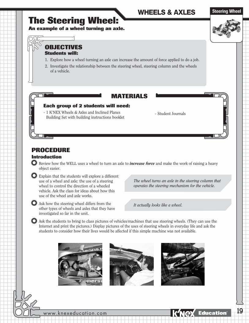
Ask the students to bring to class pictures of vehicles/machines that use steering wheels. (They can use the Internet and print the pictures.) Display pictures of the uses of steering wheels in everyday life and ask the students to consider how their lives would be affected if this simple machine was not available.
WHEELS�&�AXLES
www.knexeducat ion.com Education®
20
Building ActivityDistribute a K’NEX Wheels & Axles and Inclined Planes building set to each group.
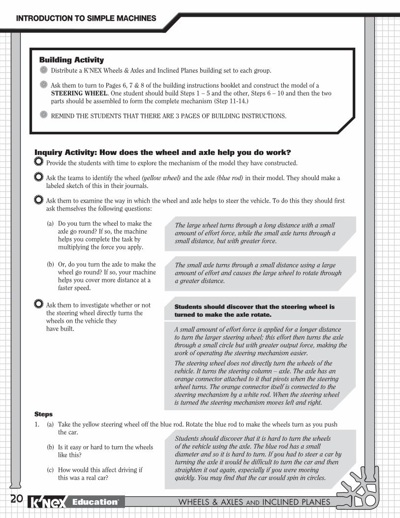
Ask them to turn to Pages 6, 7 & 8 of the building instructions booklet and construct the model of a STEERING WHEEL. One student should build Steps 1 – 5 and the other, Steps 6 – 10 and then the two parts should be assembled to form the complete mechanism (Step 11-14.)
REMIND THE STUDENTS THAT THERE ARE 3 PAGES OF BUILDING INSTRUCTIONS.
The large wheel turns through a long distance with a small amount of effort force, while the small axle turns through a small distance, but with greater force.
The small axle turns through a small distance using a large amount of effort and causes the large wheel to rotate through a greater distance.
Students should discover that it is hard to turn the wheels of the vehicle using the axle. The blue rod has a small diameter and so it is hard to turn. If you had to steer a car by turning the axle it would be difficult to turn the car and then straighten it out again, especially if you were moving quickly. You may find that the car would spin in circles.
Students should discover that the steering wheel is turned to make the axle rotate.
A small amount of effort force is applied for a longer distance to turn the larger steering wheel; this effort then turns the axle through a small circle but with greater output force, making the work of operating the steering mechanism easier.
The steering wheel does not directly turn the wheels of the vehicle. It turns the steering column – axle. The axle has an orange connector attached to it that pivots when the steering wheel turns. The orange connector itself is connected to the steering mechanism by a white rod. When the steering wheel is turned the steering mechanism moves left and right.
Inquiry Activity: How does the wheel and axle help you do work?Provide the students with time to explore the mechanism of the model they have constructed.
Ask the teams to identify the wheel (yellow wheel) and the axle (blue rod) in their model. They should make a labeled sketch of this in their journals.
Ask them to examine the way in which the wheel and axle helps to steer the vehicle. To do this they should first ask themselves the following questions:
(a) Do you turn the wheel to make the axle go round? If so, the machine helps you complete the task by multiplying the force you apply.
(b) Or, do you turn the axle to make the wheel go round? If so, your machine helps you cover more distance at a faster speed.
Ask them to investigate whether or not the steering wheel directly turns the wheels on the vehicle they have built.
Steps
1. (a) Take the yellow steering wheel off the blue rod. Rotate the blue rod to make the wheels turn as you push the car.
(b) Is it easy or hard to turn the wheels like this?
(c) How would this affect driving if this was a real car?
INTRODUCTION�TO�SIMPLE�MACHINES
WHEELS & AXLES AND INCLINED PLANESEducation®

Wheels & Axles
21
2. (a) Put the yellow steering wheel back onto the blue rod. Push the car again and steer it with the wheel.
(b) What do you notice about steering this time?
(c) Is it easier or harder than before? Why?
Students should notice that it is easier to steer the car by turning the wheel rather than the axle. The wheel is bigger than the axle so it is easier to grip and turn. The wheel moves through a greater distance than the axle but it turns with less applied effort force.
Steering Wheel
Applying The IdeaAsk the students to write in their journals why they think a car uses an actual wheel for steering instead of a handle that turns all the way around.
Encourage students to think about other vehicles with steering wheels – a bus, truck, NASCAR race car. Ask, “Do larger vehicles have larger steering wheels? How could we find out? When you find an answer, can you provide an explanation for it?”
Ask the students to draw a picture, or build a K’NEX model, of a truck or bus with an appropriately sized steering wheel.
Students should consider the fact that when driving a car, you are operating heavy machinery at high speed. You will have better control over the vehicle if you can steer with two hands.
This is an opportunity for students to collect and graph real world data before drawing a conclusion. Students should identify that trucks and buses have larger steering wheels than cars. This is because the steering mechanism is much larger and heavier so using a large diameter steering wheel needs less effort to turn. Race cars have smaller steering wheels than regular cars so they can have maximum control over the car for sharp turns at high speed. More effort, however, is needed to turn the smaller wheels.
Extending The Idea“ The K’NEX model you have built demonstrates the basic steering mechanism of a car. Using the library and
Internet, research automobiles to discover more detailed information about how steering mechanisms work. You may want to investigate the evolution of cars and the changes that have been made to the way we steer vehicles. Investigate innovations by car manufacturers to make steering easier (e.g. power steering.)”
(Visit http://www.howstuffworks.com/steering.htm [We suggest you only refer your students to the first 2 pages at this site.]
http://www.vintagecars.about.com/library/weekly/aa092698.htm)
Building Challenge“You and your friends are working on a new Scout badge for wilderness survival. For this badge you need to pretend
that you are stranded on a deserted island. You must build a vehicle that you can use to travel over land to the island’s shore and then by water to get back to civilization. You must be able to steer your vehicle and it must include different types of wheels and axles. You will also need a way to draw up and store water for your journey.
Using K’NEX, design and build this land/water vehicle. Explain how your machine operates and how it uses different wheels and axles to accomplish the task.”
WHEELS�&�AXLES
www.knexeducat ion.com Education®

22
JOURNAL CHECKAt each stage of the inquiry ask the students to keep individual journals to record their findings. The following should be recorded:
4 Identification of the wheel and axle mechanism.
4 Identification of whether the wheel or the axle is turned to make the steering mechanism work.
4 Explanation of how turning the wheel makes the task easier by multiplying the force you apply.
4 Explanation of why a wheel, and not a handle, is used to turn the axle in a vehicle.
4 Comparison of different sizes of steering wheels and the reasons for their use.
INTRODUCTION�TO�SIMPLE�MACHINES
WHEELS & AXLES AND INCLINED PLANESEducation®

Wheels & AxlesInclined PlanesBackground Information
23
KEY TERMS and DEFINITIONS for the teacher. The following is intended as a glossary for the teacher. The age of the students, their abilities, their prior knowledge, and the curriculum requirements will determine which of these terms and definitions you introduce into your classroom activities.
Simple Machine: A simple tool that makes work easier to do. Simple machines make work easier by changing the way in which the work is done, not by changing the amount of work that is needed.
Inclined Plane: A flat surface with one end higher than the other. It is used to lift a load through a vertical distance.
Screw: A rod, called the body, with an inclined plane spiraling around it. The inclined plane forms ridges, called threads, around the body of the screw. It is used to lift an object or fasten two objects together.
Wedge: A device made of 2 inclined planes arranged back to back. It is used to move one object in relation to another object.
Force: Any kind of push or pull applied to an object.
Work: The task being undertaken when using an inclined plane. In science, work refers to the use of force to move a load (object). It can be defined as follows:
W = F x D
Where W = work F = the force (effort) applied to the task D = the distance the load (object) moved
NOTE: If the object has not moved, work has not been done.
Effort: The force that is applied to move a load or overcome a resistance (ie: do work.) The force applied to a simple machine is called the effort force.
Resistance: The force exerted by the object upon which one is trying to do work; it works against the effort.
Load: The object (weight) moved or the resistance that is overcome when using an inclined plane. It exerts a force (resistance) against the inclined plane and the effort.
OBJECTIVESStudents will:1. Investigate the characteristics of inclined planes to understand how they work.
2. Recognize that screws and wedges are types of inclined planes.
3. Investigate how the use of an inclined plane affects work in relation to force, distance, speed, and direction.
4. Demonstrate how the force needed to move a load up an incline depends on the slope of the incline.
5. Construct different types of inclined planes and demonstrate how they function.
6. Analyze objects/tools in terms of their application as inclined planes.
INTRODUCTION�TO�SIMPLE�MACHINES
www.knexeducat ion.com Education®
24
= MASlope length
Slope height
12’3’
Slope: A measure of the steepness of an incline.
Friction: The forced caused when 2 surfaces rub together as an object moves.
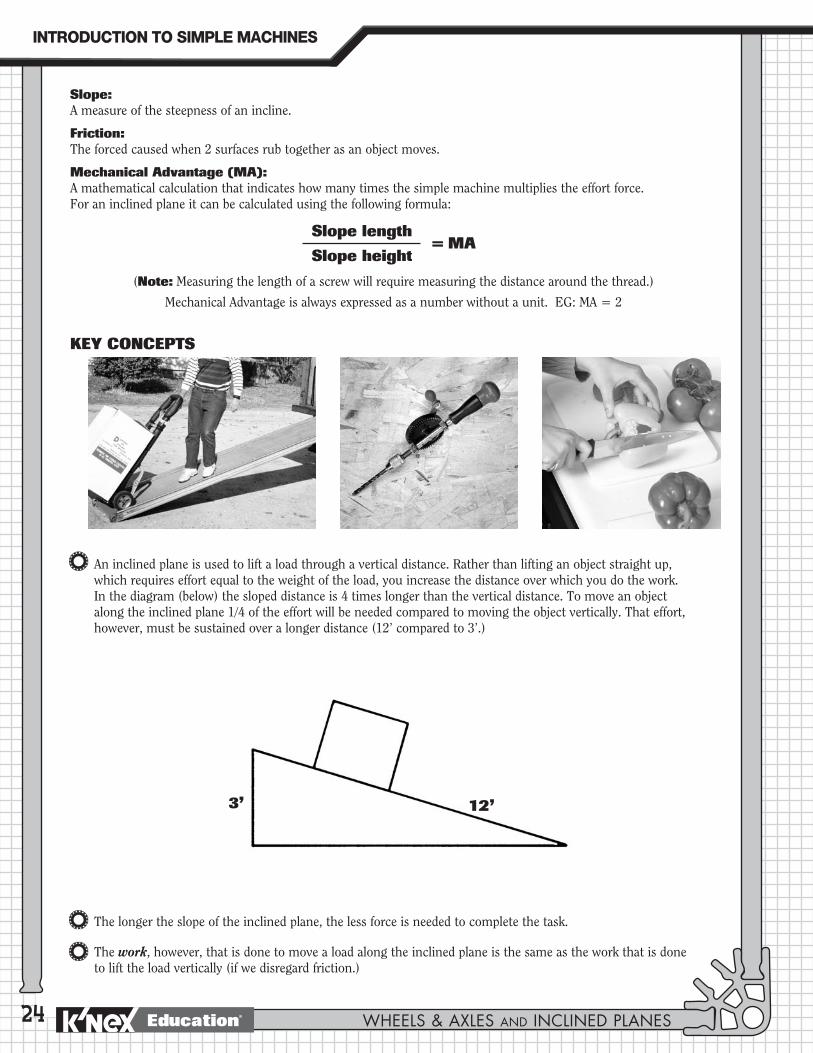
Mechanical Advantage (MA): A mathematical calculation that indicates how many times the simple machine multiplies the effort force. For an inclined plane it can be calculated using the following formula:
(Note: Measuring the length of a screw will require measuring the distance around the thread.)
Mechanical Advantage is always expressed as a number without a unit. EG: MA = 2
KEY CONCEPTS
An inclined plane is used to lift a load through a vertical distance. Rather than lifting an object straight up, which requires effort equal to the weight of the load, you increase the distance over which you do the work. In the diagram (below) the sloped distance is 4 times longer than the vertical distance. To move an object along the inclined plane 1/4 of the effort will be needed compared to moving the object vertically. That effort, however, must be sustained over a longer distance (12’ compared to 3’.)
The longer the slope of the inclined plane, the less force is needed to complete the task.
The work, however, that is done to move a load along the inclined plane is the same as the work that is done to lift the load vertically (if we disregard friction.)
12’3’
INTRODUCTION�TO�SIMPLE�MACHINES
WHEELS & AXLES AND INCLINED PLANESEducation®

Wheels & Axles
25
Objects are moved along the slope of the inclined plane; the inclined plane does not normally move.
Inclined planes can also be used to control the rate of descent of an object from a height.
Screws increase the distance over which you apply the effort force, but reduce the amount of effort force needed. The distance around the threads of a screw is longer than the length of the screw itself. This means that traveling around the threads of the screw is longer, but easier than traveling straight up. For example, it requires less effort to climb a spiral staircase than it does a ladder, but you climb more steps and cover a greater distance to get to the same place.
Wedges change the direction of the applied force and increase the force on the objects being separated; when pushing down on a wedge, the object it is pushing against moves sideways so that the direction of the two forces is at right angles to each other.
If the wedge is long and thin, it separates the sides of the object it is being driven into a small distance with a small applied effort force. If the wedge is short and fat, the sides of the object will be separated a greater distance but to achieve this will require a greater applied effort force.
The blade of a knife is a wedge. As the blade (wedge) is pushed down through, for example, a piece of cheese, it separates a slice from the block.
Wedges and screws are both types of inclined planes that move in order to carry out their functions.
INCLINED�PLANES
www.knexeducat ion.com Education®

26

Wheels & AxlesSteep & Long Ramps: Examples of inclined planes.
Ramps
27
OBJECTIVESStudents will:1. Investigate the characteristics of an inclined plane.
2. Understand how the use of an inclined plane affects work in relation to force, distance, speed and direction.
3. Compare inclined planes with different angles to determine the effort needed to raise an object.
MATERIALSEach group of 2 students will need: - 1 K’NEX Wheels & Axles and
Inclined Planes Building Set with building instructions booklet
- Ruler/tape measure
- A piece of heavy rubber band, approximately 4-6 inches (10-15 cms.) long
- Student Journals
- 400 gram or 10 Newton spring scale (optional)
- 3 secured rolls of pennies, gram weights or other weighted objects (Make sure you select objects that are heavy and that, if using rolls of pennies, the 3 rolls are firmly secured before you distribute them to the students.)
PROCEDUREIntroduction
Review with the students the way in which simple machines help do work – not by changing the amount of work that is needed but by changing the way in which it is done.
Ask the students to consider an activity that they do every day, namely moving themselves, or an object, from one level to another. What do they use to help them? (Stairs, steps, ladders, ramps.)
Explain that the students will be investigating a simple machine, the inclined plane, that allows them to use less effort to move an object up or down, although they will need to move the object over a longer distance than if they were lifting it vertically.
Provide the class with a definition of an inclined plane and draw a diagram on the board to shown its features. (See Key Concepts above.)
INCLINED�PLANES
www.knexeducat ion.com Education®

28
Ask the students to think about places where they have seen inclined planes (ramps) used to move a person or an object to a higher position.
The school building should provide examples of wheelchair ramps and possibly a ramp at a loading dock. If possible, take the children to investigate them. They should note the steepness of the ramp; suggest reasons why the ramp was used in that particular location; and understand that, whether they step up onto the curb (or steps), or use the ramp, they have moved vertically and arrived at the same place. Ramps simply make it easier to get to that place.
Encourage the students to use the library or Internet to investigate how inclined planes are used. (For example: Macaulay, D. The Way Things Work. Or visit http://www.professorbeaker.com/plane_fact.html)
Ramps in the sidewalk for wheelchairs; ramps to load heavy objects onto trucks; ramps between levels in a mall or sports stadium.
Building ActivityDistribute the K’NEX Wheels & Axles and Inclined Planes building set to each group.
Ask them to turn to Pages 9, 10 & 11 of the building instructions booklet and construct the models of the STEEP RAMP and the LONG RAMP. One team member should build the Steep Ramp and the other, the Long Ramp.
Building Tip for Step 7 for the LONG RAMP: Slide the first section of the ramp over the yellow connectors, THEN slip in the white joining plate to the end of the first section of ramp. Finally slide the second section of ramp over the yellow connectors until it meets the white joining plate. Slide it over the joining plate to close the gap and complete the entire length of ramp.
NOTE: Make sure that both models are constructed so that the bottom end of the black plastic ramp touches the desktop. Both ramps are designed to move an object through the same vertical distance and to ensure this, correct positioning on the support structure is essential.
Inquiry Activity: How does the inclined plane help make work easier?Explain that they will be investigating the K’NEX Steep and Long Ramps by pulling different objects up them. Remind the students that the purpose of the inclined plane (ramp) is to make work easier by reducing the amount of force needed to move an object.
Steps
1. (a) Measure the heights of the two ramps and the lengths of their sloping sides. What do you notice?
(b) Draw diagrams in your journals to represent the ramps and record your measurements on them.
2. (a) Give each group 3 rolls of pennies (or another weighted object,) and a 4-6 inch (10-15 cms.) length of heavy rubber band. (NOTE: Before distributing the rubber bands, make sure the students understand that over-extending them can result in a snap back or loss of control; they need to be very careful. See Safety Information at the beginning of the Guide.)
(b) Tie the rubber band to the weight, making sure that there is a length for you to hold. One member of the group should hold this end of the rubber band and lift the weight vertically so that it is level with the top of the ramps. Notice how it feels to lift the weight.
Students should notice that the vertical height of the two ramps is the same, but the length of the sloping side of one is longer than that of the other.
INTRODUCTION�TO�SIMPLE�MACHINES
WHEELS & AXLES AND INCLINED PLANESEducation®

Wheels & Axles
29
Students should say that it is difficult to lift the weight vertically. The stretched rubber band shows the amount of force needed to raise the weight through the vertical distance. Since the rubber band is very stretched, a large effort force is needed to lift the weight vertically.
Students should notice that it is easier to pull the weight up the incline than to lift it vertically. Because of this the rubber band is less stretched when using the ramp. Students should notice a marked difference in the length of the rubber band when using the ramp. They should state that it takes less force to lift the weight using the ramp, which is why the rubber band is less stretched.
Students should notice that the rubber band is even less stretched when using the long ramp than with the steep ramp. This shows that it takes less force to move something up a long, more gently sloping incline, than a short, steep one. However, you have to move it over a longer distance.
Ramps
(c) The other member of the group should measure and record the length of the stretched rubber band.
(d) What do you think the stretched rubber band shows?
3. (a) Pull the weight up the slope of the steep (short) ramp. Hold the rubber band in exactly the same place as when you lifted the weight vertically (STEP 2 above.)
(b) Measure and record the length of the rubber band when the weight is almost at the top.
(c) How does this compare to lifting the weight without the ramp?
(d) What do you think this means?
4. (a) Pull the same weight up the slope of the long ramp. Again, measure and record the length of the rubber band when the weight is almost at the top.
(b) How does this compare to pulling the weight up the steep ramp?
(c) What does this show?
Applying The IdeaAsk the students to write in their journals about other situations where they would use an inclined plane and why.
When they have completed their writing ask them to share their ideas with the rest of the group. Encourage the students to discuss factors that may be involved in determining what the slope of the incline (gradient) should be. Ask them to consider situations where a short, steep slope is preferred, such as a sliding board or a roller coaster, and where a long, gentle slope is preferred, such as a mountain trail or wheel chair ramp.
INCLINED�PLANES
www.knexeducat ion.com Education®

30
JOURNAL CHECK4 Measurement of ramp lengths and heights with diagrams.
4 Rubber band force measurements.
4 Explanation of the benefits of gradual/steep inclined planes.
4 List of examples of inclined planes and descriptions of how they help make work easier.
Applying The Idea (continued)Ask the students to complete the following sentence describing the force needed to move an object up an inclined plane:
Their completed sentences should be written in their journals.
Extending The Idea1. (a) Determine the actual amount of force used to pull the weight up the inclined plane by using a spring scale.
Attach the spring scale to the weight and conduct the experiments from STEP 2 again.
(b) In the activity, both the weight and the inclined plane had a smooth surface. Think about how friction can affect the work done with an inclined plane.
(c) Would a rough object moving along a rough inclined plane require more force to raise the object compared to simply lifting it?
(d) Would it require more force than moving a rough object up a smooth inclined plane?
(e) Would wheels on the object have any effect on the force required to move it up the incline? Why or why not?
(f) Conduct experiments to determine how friction affects movement on an inclined plane. For example, cover the ramps with a terry towel or similar cloth. Try to pull a wheeled vehicle up the incline. Discuss your findings.
2. Ask the students to calculate and compare the Mechanical Advantage of the steep ramp and the long ramp.
This can be calculated using the following formula:
The steeper the slope of the inclined plane…
(the more force required to move the object up the incline.)
= MASlope length
Slope height
INTRODUCTION�TO�SIMPLE�MACHINES
WHEELS & AXLES AND INCLINED PLANESEducation®
Wheels & AxlesThe Splitting Wedge: An example of a wedge.
Wedge
31
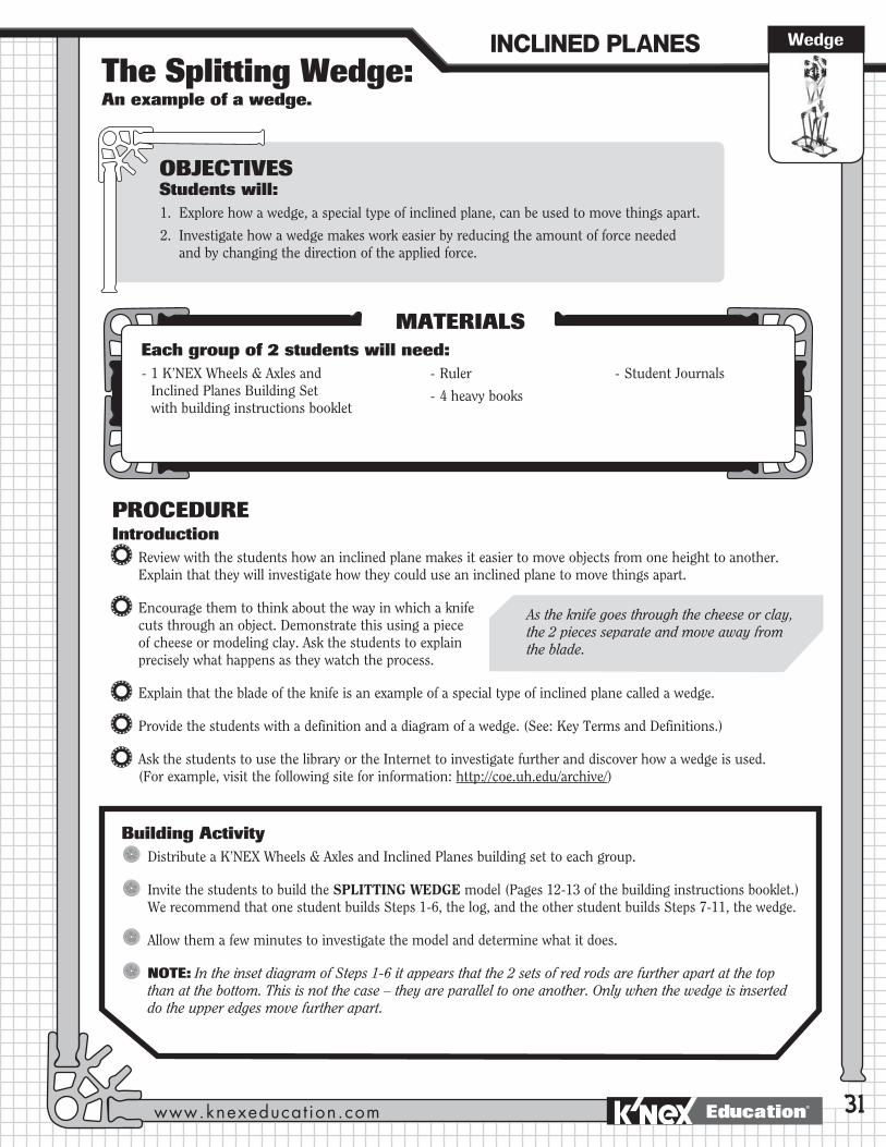
OBJECTIVESStudents will:1. Explore how a wedge, a special type of inclined plane, can be used to move things apart.
2. Investigate how a wedge makes work easier by reducing the amount of force needed and by changing the direction of the applied force.
MATERIALSEach group of 2 students will need: - 1 K’NEX Wheels & Axles and
Inclined Planes Building Set with building instructions booklet
- Ruler
- 4 heavy books
- Student Journals
PROCEDUREIntroduction
Review with the students how an inclined plane makes it easier to move objects from one height to another. Explain that they will investigate how they could use an inclined plane to move things apart.
Encourage them to think about the way in which a knife cuts through an object. Demonstrate this using a piece of cheese or modeling clay. Ask the students to explain precisely what happens as they watch the process.
Explain that the blade of the knife is an example of a special type of inclined plane called a wedge.
Provide the students with a definition and a diagram of a wedge. (See: Key Terms and Definitions.)
Ask the students to use the library or the Internet to investigate further and discover how a wedge is used. (For example, visit the following site for information: http://coe.uh.edu/archive/)
As the knife goes through the cheese or clay, the 2 pieces separate and move away from the blade.
Building ActivityDistribute a K’NEX Wheels & Axles and Inclined Planes building set to each group.
Invite the students to build the SPLITTING WEDGE model (Pages 12-13 of the building instructions booklet.) We recommend that one student builds Steps 1-6, the log, and the other student builds Steps 7-11, the wedge.
Allow them a few minutes to investigate the model and determine what it does.
NOTE: In the inset diagram of Steps 1-6 it appears that the 2 sets of red rods are further apart at the top than at the bottom. This is not the case – they are parallel to one another. Only when the wedge is inserted do the upper edges move further apart.
INCLINED�PLANES
www.knexeducat ion.com Education®
32
Inquiry Activity: How does the splitting wedge help you do work?Review with the students the fact that wedges are actually inclined planes that move. Their purpose is to make work easier by reducing the amount of effort force that is needed to do the job. The students will determine how they do this by using the model they have constructed.
Steps
1. Look at the splitting wedge. Think about why it is considered to be a type of inclined plane.
2. (a) Set the edge of the splitting wedge (constructed in Steps 7-11 of the building activity,) between the two sides of the ‘log’ so that it is approximately half way down the first set of blue rods.
(b) Measure and record the distance between the top edges of the ‘log’.
(c) Push the wedge in further and measure again. What do you notice?
3. Draw and label a diagram to show in which directions the wedge and the ‘log’ halves have moved.
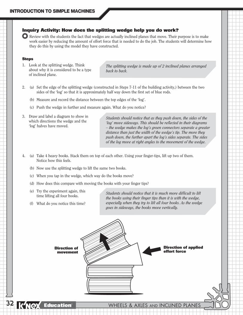
4. (a) Take 4 heavy books. Stack them on top of each other. Using your finger-tips, lift up two of them. Notice how this feels.
(b) Now use the splitting wedge to lift the same two books.
(c) When you tap in the wedge, which way do the books move?
(d) How does this compare with moving the books with your finger tips?
(e) Try the experiment again, this time lifting all four books.
(f) What do you notice this time?
The splitting wedge is made up of 2 inclined planes arranged back to back.
Students should notice that as they push down, the sides of the ‘log’ move sideways. This should be reflected in their diagrams – the wedge makes the log’s green connectors separate a greater distance than just the width of the wedge’s tip. The more they push down, the further apart the log’s sides separate. The sides of the log move at right angles to the movement of the wedge.
Students should notice that it is much more difficult to lift the books using their finger tips than it is with the wedge, especially when they try to lift all four books. As the wedge goes in sideways, the books move vertically.
Direction of applied effort force
Direction of movement
INTRODUCTION�TO�SIMPLE�MACHINES
WHEELS & AXLES AND INCLINED PLANESEducation®

Wheels & Axles
33
Applying The IdeaAsk Ask the students to record in their
journals how a splitting wedge functions as inclined plane and also how it is different from the inclined planes they have used in the previous activity.
Encourage the students to think of other machines that function like a splitting wedge. Ask them to draw a picture or build a K’NEX model of one of the machines and explain how it works.
Extending The Idea1. Using wedges, Abraham Lincoln
earned himself a nickname, The Railsplitter. Use the library or Internet to research the life of Abraham Lincoln to find out how he got his name and how he used wedges.
(Visit http://lincoln.lib.niu.edu/ for information about the early years in the life of Abraham Lincoln.)
2. Ask the students to calculate the Mechanical Advantage of the K’NEX splitting wedge. This can be calculated using the following formula:
Students should note that wedges make it easier to raise objects up and this makes them like inclined planes. They are different because the wedge changes the direction of the force. Instead of an object moving up a slope, the slope (wedge) is moving under the object to lift it. Unlike most inclined planes, the wedge moves when it is used.
When Lincoln was a boy, he helped his father clear the land in a wooded area in Indiana, where he lived. He used an axe, a type of wedge, to cut trees. Later on in life, he worked for others chopping firewood for heating and cooking, cutting logs for houses and splitting rails for fences and cabins. To split a log into rails, he would drive a wedge into the log. He was given the nickname “The Railsplitter” when he ran for political office in 1860. It reminded voters of his background and helped them relate to him.
Other examples include a fork, axe, chisel.
Wedge
= MASlope length x 2
Thickness of the end you strike
INCLINED�PLANES
www.knexeducat ion.com Education®
34
JOURNAL CHECK4 Diagram and definition of a wedge.
4 Distance measurements.
4 Diagram of the direction that work is performed, with labels for distance and direction.
4 Explanation of how the wedge functions as an inclined plane and how it differs from other inclined planes they have used.
4 List of everyday wedges, with diagrams.
INTRODUCTION�TO�SIMPLE�MACHINES
WHEELS & AXLES AND INCLINED PLANESEducation®
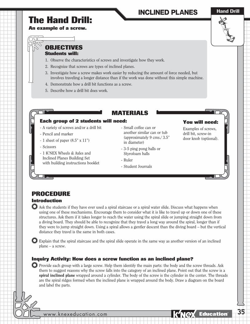
Wheels & AxlesThe Hand Drill: An example of a screw.
Hand Drill
35
OBJECTIVESStudents will:1. Observe the characteristics of screws and investigate how they work.
2. Recognize that screws are types of inclined planes.
3. Investigate how a screw makes work easier by reducing the amount of force needed, but involves traveling a longer distance than if the work was done without this simple machine.
4. Demonstrate how a drill bit functions as a screw.
5. Describe how a drill bit does work.
MATERIALSEach group of 2 students will need: - A variety of screws and/or a drill bit
- Pencil and marker
- 1 sheet of paper (8.5” x 11”)
- Scissors
- 1 K’NEX Wheels & Axles and Inclined Planes Building Set with building instructions booklet
- Small coffee can or another similar can or tub (approximately 9 cms./ 3.5” in diameter)
- 3-5 ping pong balls or Styrofoam balls
- Ruler
- Student Journals
PROCEDUREIntroduction
Ask the students if they have ever used a spiral staircase or a spiral water slide. Discuss what happens when using one of these mechanisms. Encourage them to consider what it is like to travel up or down one of these structures. Ask them if it takes longer to reach the water using the spiral slide or jumping straight down from a diving board. They should be able to recognize that they travel a long way around the spiral, longer than if they were to jump straight down. Using a spiral allows a gentler descent than the diving board – but the vertical distance they travel is the same in both cases.
Explain that the spiral staircase and the spiral slide operate in the same way as another version of an inclined plane – a screw.
Inquiry Activity: How does a screw function as an inclined plane?Provide each group with a large screw. Help them identify the main parts: the body and the screw threads. Ask them to suggest reasons why the screw falls into the category of an inclined plane. Point out that the screw is a spiral inclined plane wrapped around a cylinder. The body of the screw is the cylinder in the center. The threads are the spiral ridges formed when the inclined plane is wrapped around the body. Draw a diagram on the board and label the parts.
You will need:Examples of screws, drill bit, screw-in door knob (optional).
INCLINED�PLANES
www.knexeducat ion.com Education®

36
Explain to the students that they can easily demonstrate that the screw is a spiral inclined plane.
Ask the students to take a piece of paper (8.5” x 11”). Fold the bottom edge over so that it lines up with the left hand edge. Cut along the diagonal fold to create a right triangle.
Ask the students to take a marker and draw a thick line along the long sloping edge. Ask them what they think this edge represents. They should recognize that it represents an inclined plane. Ask them to notice the difference in length between the slope of the inclined plane and the other two sides.
Tell the students to place the paper triangle on the desk with the marked side facing down and oriented so the two unmarked shorter edges are at the top and left hand side. Place a pencil on the paper at the top and wrap the paper triangle around it until the pencil reaches the bottom of the paper. (Demonstrate this to the class first.)
Ask them to look at the marked edge of the inclined plane. They should discover that it spirals into a screw shape.
Encourage the students to use the Internet to investigate further the function of a screw. (For example, visit http://teacher.scholastic.com/dirtrep/simple/screw.htm)
Threads
Body
Threads
Body
INTRODUCTION�TO�SIMPLE�MACHINES
WHEELS & AXLES AND INCLINED PLANESEducation®
Wheels & Axles
37
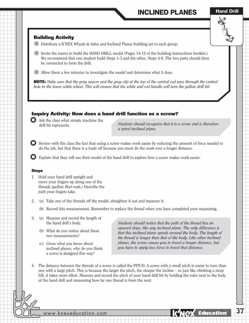
Building ActivityDistribute a K’NEX Wheels & Axles and Inclined Planes building set to each group.
Invite the teams to build the HAND DRILL model (Pages 14-15 of the building instructions booklet.) We recommend that one student build Steps 1-3 and the other, Steps 4-6. The two parts should then be connected to form the drill.
Allow them a few minutes to investigate the model and determine what it does.
NOTE: Make sure that the gray spacer and the gray clip at the top of the central rod pass through the central hole in the lower white wheel. This will ensure that the white and red handle will turn the yellow drill bit.
Hand Drill
Inquiry Activity: How does a hand drill function as a screw?Ask the class what simple machine the drill bit represents.
Review with the class the fact that using a screw makes work easier by reducing the amount of force needed to do the job, but that there is a trade off because you must do the work over a longer distance.
Explain that they will use their model of the hand drill to explore how a screw makes work easier.
Steps
1. Hold your hand drill upright and move your fingers up along one of the threads (yellow flexi-rods.) Describe the path your fingers take.
2. (a) Take one of the threads off the model, straighten it out and measure it.
(b) Record this measurement. Remember to replace the thread when you have completed your measuring.
3. (a) Measure and record the length of the hand drill’s body.
(b) What do you notice about these two measurements?
(c) Given what you know about inclined planes, why do you think a screw is designed this way?
4. The distance between the threads of a screw is called the PITCH. A screw with a small pitch is easier to turn than one with a large pitch. This is because the larger the pitch, the steeper the incline – so just like climbing a steep hill, it takes more effort. Measure and record the pitch of your hand drill bit by holding the ruler next to the body of the hand drill and measuring how far one thread is from the next.
Students should recognize that it is a screw and is therefore a spiral inclined plane.
Students should notice that the path of the thread has an upward slope, like any inclined plane. The only difference is that this inclined plane spirals around the body. The length of the thread is longer than that of the body. Like other inclined planes, the screw causes you to travel a longer distance, but you have to apply less force to travel that distance.
INCLINED�PLANES
www.knexeducat ion.com Education®
38
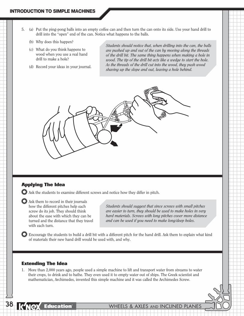
5. (a) Put the ping-pong balls into an empty coffee can and then turn the can onto its side. Use your hand drill to drill into the “open” end of the can. Notice what happens to the balls.
(b) Why does this happen?
(c) What do you think happens to wood when you use a real hand drill to make a hole?
(d) Record your ideas in your journal.
Applying The Idea
Ask the students to examine different screws and notice how they differ in pitch.
Ask them to record in their journals how the different pitches help each screw do its job. They should think about the ease with which they can be turned and the distance that they travel with each turn.
Encourage the students to build a drill bit with a different pitch for the hand drill. Ask them to explain what kind of materials their new hand drill would be used with, and why.
Extending The Idea1. More than 2,000 years ago, people used a simple machine to lift and transport water from streams to water
their crops, to drink and to bathe. They even used it to empty water out of ships. The Greek scientist and mathematician, Archimedes, invented this simple machine and it was called the Archimedes Screw.
Students should notice that, when drilling into the can, the balls are pushed up and out of the can by moving along the threads of the drill bit. The same thing happens when making a hole in wood. The tip of the drill bit acts like a wedge to start the hole. As the threads of the drill cut into the wood, they push wood shaving up the slope and out, leaving a hole behind.
Students should suggest that since screws with small pitches are easier to turn, they should be used to make holes in very hard materials. Screws with long pitches cover more distance and can be used if you need to make long/deep holes.
INTRODUCTION�TO�SIMPLE�MACHINES
WHEELS & AXLES AND INCLINED PLANESEducation®

Wheels & Axles
39
Hand Drill
JOURNAL CHECK4 Labeled diagram of the parts of a screw with definition.
4 Comparison of a drill bit to the inclined plane.
4 Comparison of the balls being drilled out of the can with the appearance of wood or metal shavings when a real drill is used.
4 List of drill bits with different pitches and the jobs they do.
= MASlope length (length of the spiral)
Slope height (length of the body )
Using the library and Internet, investigate the Archimedes Screw to learn about its design and how it worked. Using K’NEX, design and build an Archimedes Screw. Discuss how people used it 2,000 years ago and how it is still used today.
2. Ask the students to calculate the Mechanical Advantage of a screw or drill bit. This can be calculated using the following formula:
Building Challenge“Imagine that you own a bowling ball factory. You need a machine that you can use to take the balls off the assembly line and put them into boxes. The balls should feed in from the bottom of the machine and then drop off the top into a box. You also need a way to move the boxes from the loading dock onto the delivery trucks.
Using K’NEX, design and build the machines that your factory needs in order to accomplish these tasks. Be sure to include at least TWO of the three types of inclined planes – inclined plane, wedge and screw. Explain how your machines operate and how they incorporate inclined planes to accomplish the tasks.”
The Archimedes Screw consists of a screw inside a cylinder, with an opening at each end and with a handle on one end of the screw mechanism. Water is heavy and it is difficult to lift and transport large quantities at one time. The end of the cylinder without the handle is lowered into the body of water - a river, for example. The handle on the upper end of the screw is turned and water enters into the screw at its lower end and moves up the spiral, finally exiting at the upper end. In the past, the Archimedes Screw was used almost any time people had to transfer water from a river or lake to a higher elevation. Today, Archimedes Screws are typically used for irrigation, transferring grain and removing rubble from excavation sites.
Visit http://www.mcs.drexel.edu/~corres/Archimedes/contents.html for information about the Archimedes Screw.
Source: American Museum of Natural History.
INCLINED�PLANES
www.knexeducat ion.com Education®


![Cambridge Assessment International Education Cambridge ... (0625)/0625_s19_qp_31.pdf · order student 1st 2nd 3rd B 4th 5th [2] ... Calculate the pressure exerted on the top surface](https://static.fdocuments.us/doc/165x107/5e87082fc058452a357905ef/cambridge-assessment-international-education-cambridge-06250625s19qp31pdf.jpg)

