EDR..71 – 315, EDRN63 – 315
16
*26859823_1020* Drive Technology \ Drive Automation \ System Integration \ Services Revision Explosion-Protected AC Motors EDR..71 – 315, EDRN63 – 315 Edition 10/2020 26859823/EN
Transcript of EDR..71 – 315, EDRN63 – 315
*26859823_1020*Drive Technology \ Drive Automation \ System Integration \ Services
Revision
Explosion-Protected AC MotorsEDR..71 – 315, EDRN63 – 315
Edition 10/2020 26859823/EN

SEW-EURODRIVE—Driving the world
1Revision
Revision – EDR..71 – 315, EDRN63 – 315 3
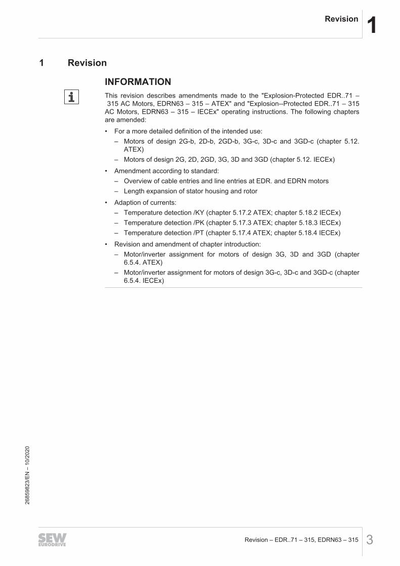
1 Revision
INFORMATIONThis revision describes amendments made to the "Explosion-Protected EDR..71 – 315 AC Motors, EDRN63 – 315 – ATEX" and "Explosion--Protected EDR..71 – 315AC Motors, EDRN63 – 315 – IECEx" operating instructions. The following chaptersare amended:• For a more detailed definition of the intended use:
– Motors of design 2G-b, 2D-b, 2GD-b, 3G-c, 3D-c and 3GD-c (chapter 5.12.ATEX)
– Motors of design 2G, 2D, 2GD, 3G, 3D and 3GD (chapter 5.12. IECEx)• Amendment according to standard:
– Overview of cable entries and line entries at EDR. and EDRN motors– Length expansion of stator housing and rotor
• Adaption of currents:– Temperature detection /KY (chapter 5.17.2 ATEX; chapter 5.18.2 IECEx)– Temperature detection /PK (chapter 5.17.3 ATEX; chapter 5.18.3 IECEx)– Temperature detection /PT (chapter 5.17.4 ATEX; chapter 5.18.4 IECEx)
• Revision and amendment of chapter introduction:– Motor/inverter assignment for motors of design 3G, 3D and 3GD (chapter
6.5.4. ATEX)– Motor/inverter assignment for motors of design 3G-c, 3D-c and 3GD-c (chapter
6.5.4. IECEx)
2685
9823
/EN
– 1
0/20
20
2 Electrical installationMotors of design 2G, 2D, 2GD, 3G, 3D and 3GD
Revision – EDR..71 – 315, EDRN63 – 3154
2 Electrical installation
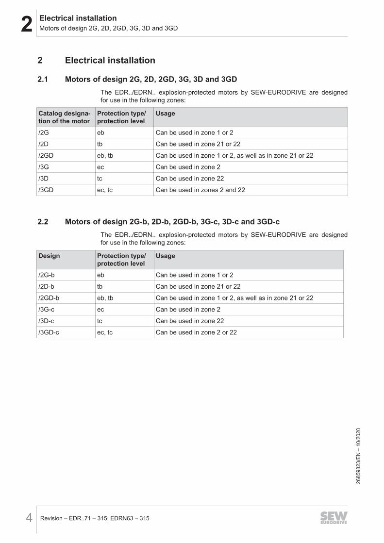
2.1 Motors of design 2G, 2D, 2GD, 3G, 3D and 3GDThe EDR../EDRN.. explosion-protected motors by SEW‑EURODRIVE are designedfor use in the following zones:
Catalog designa-tion of the motor
Protection type/protection level
Usage
/2G eb Can be used in zone 1 or 2
/2D tb Can be used in zone 21 or 22
/2GD eb, tb Can be used in zone 1 or 2, as well as in zone 21 or 22
/3G ec Can be used in zone 2
/3D tc Can be used in zone 22
/3GD ec, tc Can be used in zones 2 and 22
2.2 Motors of design 2G-b, 2D-b, 2GD-b, 3G-c, 3D-c and 3GD-cThe EDR../EDRN.. explosion-protected motors by SEW‑EURODRIVE are designedfor use in the following zones:
Design Protection type/protection level
Usage
/2G-b eb Can be used in zone 1 or 2
/2D-b tb Can be used in zone 21 or 22
/2GD-b eb, tb Can be used in zone 1 or 2, as well as in zone 21 or 22
/3G-c ec Can be used in zone 2
/3D-c tc Can be used in zone 22
/3GD-c ec, tc Can be used in zone 2 or 22
2685
9823
/EN
– 1
0/20
20
2Electrical installationOverview of cable entries and line entries at EDR. and EDRN motors
Revision – EDR..71 – 315, EDRN63 – 315 5
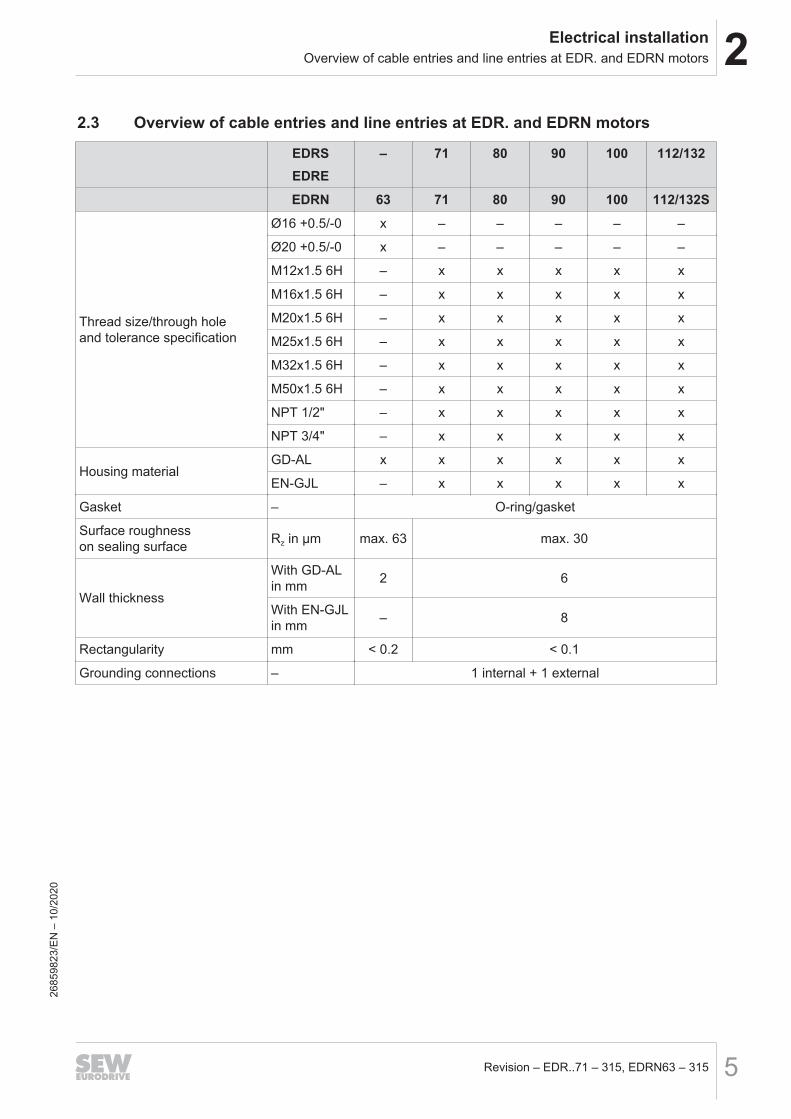
2.3 Overview of cable entries and line entries at EDR. and EDRN motors
EDRSEDRE
– 71 80 90 100 112/132
EDRN 63 71 80 90 100 112/132S
Thread size/through holeand tolerance specification
Ø16 +0.5/-0 x – – – – –
Ø20 +0.5/-0 x – – – – –
M12x1.5 6H – x x x x x
M16x1.5 6H – x x x x x
M20x1.5 6H – x x x x x
M25x1.5 6H – x x x x x
M32x1.5 6H – x x x x x
M50x1.5 6H – x x x x x
NPT 1/2" – x x x x x
NPT 3/4" – x x x x x
Housing materialGD-AL x x x x x x
EN-GJL – x x x x x
Gasket – O-ring/gasket
Surface roughnesson sealing surface Rz in µm max. 63 max. 30
Wall thickness
With GD-ALin mm 2 6
With EN-GJLin mm – 8
Rectangularity mm < 0.2 < 0.1
Grounding connections – 1 internal + 1 external
2685
9823
/EN
– 1
0/20
20

2 Electrical installationOverview of cable entries and line entries at EDR. and EDRN motors
Revision – EDR..71 – 315, EDRN63 – 3156
EDRSEDRE
– 160 180 200 225 250/280 315
EDRN 132M/L 160 180 200 225 250 315
Thread size/through holeand tolerance specification
M12x1.5 6H x x x x x – –
M16x1.5 6H x x x x x x x
M20x1.5 6H x x x x x – –
M25x1.5 6H x x x x x – x
M32x1.5 6H x x x – – – –
M40x1.5 6H x x x x x – x
M50x1.5 6H x x x x x – –
M63x1.5 6H – – – x x x x
NPT 1/2" x x x x x x –
NPT 3/4" x – – – – – –
NPT 1 1/4" x x x x x – –
NPT 1 1/2" x x x x x – –
NPT 2 1/2" – – – – – x –
Housing materialGD-AL x x x x x – –
EN-GJL x x x x x x x
Gasket – O-ring/gasket
Surface roughnesson sealing surface Rz in µm max. 30
Wall thickness
With GD-ALin mm 7.5 –
With EN-GJLin mm 7 7.5
Rectangularity mm < 0.1
Grounding connections – 1 internal + 1 external26
8598
23/E
N –
10/
2020
2Electrical installationTemperature detection /KY (KTY84 – 130)
Revision – EDR..71 – 315, EDRN63 – 315 7
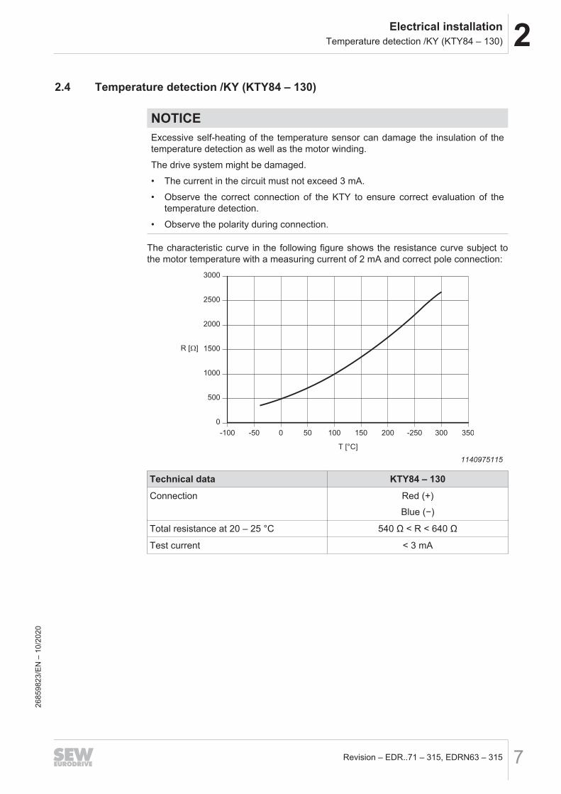
2.4 Temperature detection /KY (KTY84 – 130)
NOTICEExcessive self-heating of the temperature sensor can damage the insulation of thetemperature detection as well as the motor winding.The drive system might be damaged.• The current in the circuit must not exceed 3 mA.• Observe the correct connection of the KTY to ensure correct evaluation of the
temperature detection.• Observe the polarity during connection.
The characteristic curve in the following figure shows the resistance curve subject tothe motor temperature with a measuring current of 2 mA and correct pole connection:
0
500
1000
1500
2000
2500
3000
-100 -50 0 50 100 150 200 -250 300 350
T [°C]
R [Ω]
1140975115
Technical data KTY84 – 130Connection Red (+)
Blue (−)
Total resistance at 20 – 25 °C 540 Ω < R < 640 Ω
Test current < 3 mA
2685
9823
/EN
– 1
0/20
20
2 Electrical installationTemperature detection /PK (PT1000)
Revision – EDR..71 – 315, EDRN63 – 3158
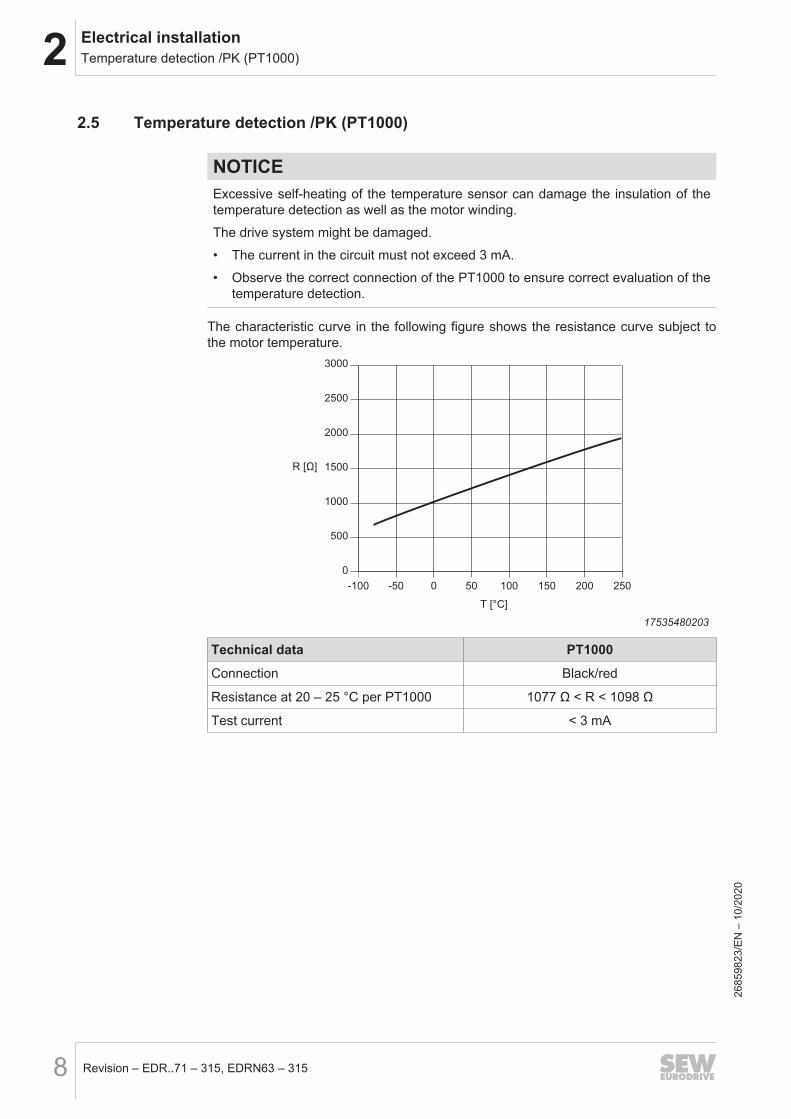
2.5 Temperature detection /PK (PT1000)
NOTICEExcessive self-heating of the temperature sensor can damage the insulation of thetemperature detection as well as the motor winding.The drive system might be damaged.• The current in the circuit must not exceed 3 mA.• Observe the correct connection of the PT1000 to ensure correct evaluation of the
temperature detection.
The characteristic curve in the following figure shows the resistance curve subject tothe motor temperature.
0
500
1000
1500
2000
2500
3000
-100 -50 0 50 100 150 200 250
T [°C]
R [Ω]
17535480203
Technical data PT1000Connection Black/red
Resistance at 20 – 25 °C per PT1000 1077 Ω < R < 1098 Ω
Test current < 3 mA26
8598
23/E
N –
10/
2020
2Electrical installationTemperature sensor /PT (PT100)
Revision – EDR..71 – 315, EDRN63 – 315 9
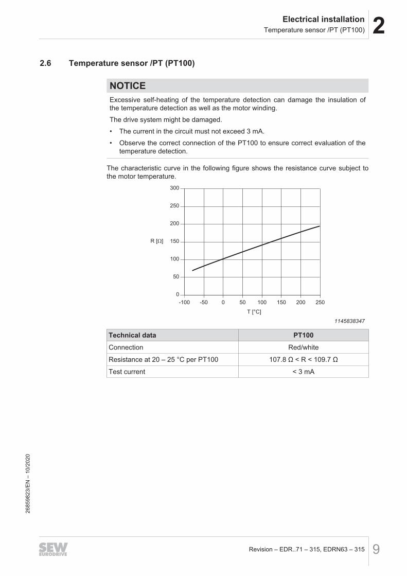
2.6 Temperature sensor /PT (PT100)
NOTICEExcessive self-heating of the temperature detection can damage the insulation ofthe temperature detection as well as the motor winding.The drive system might be damaged.• The current in the circuit must not exceed 3 mA.• Observe the correct connection of the PT100 to ensure correct evaluation of the
temperature detection.
The characteristic curve in the following figure shows the resistance curve subject tothe motor temperature.
0
50
100
150
200
250
300
-100 -50 0 50 100 150 200 250
T [°C]
R [Ω]
1145838347
Technical data PT100Connection Red/white
Resistance at 20 – 25 °C per PT100 107.8 Ω < R < 109.7 Ω
Test current < 3 mA
2685
9823
/EN
– 1
0/20
20
3 Mechanical installationLength expansion of stator housing and rotor
Revision – EDR..71 – 315, EDRN63 – 31510
3 Mechanical installation
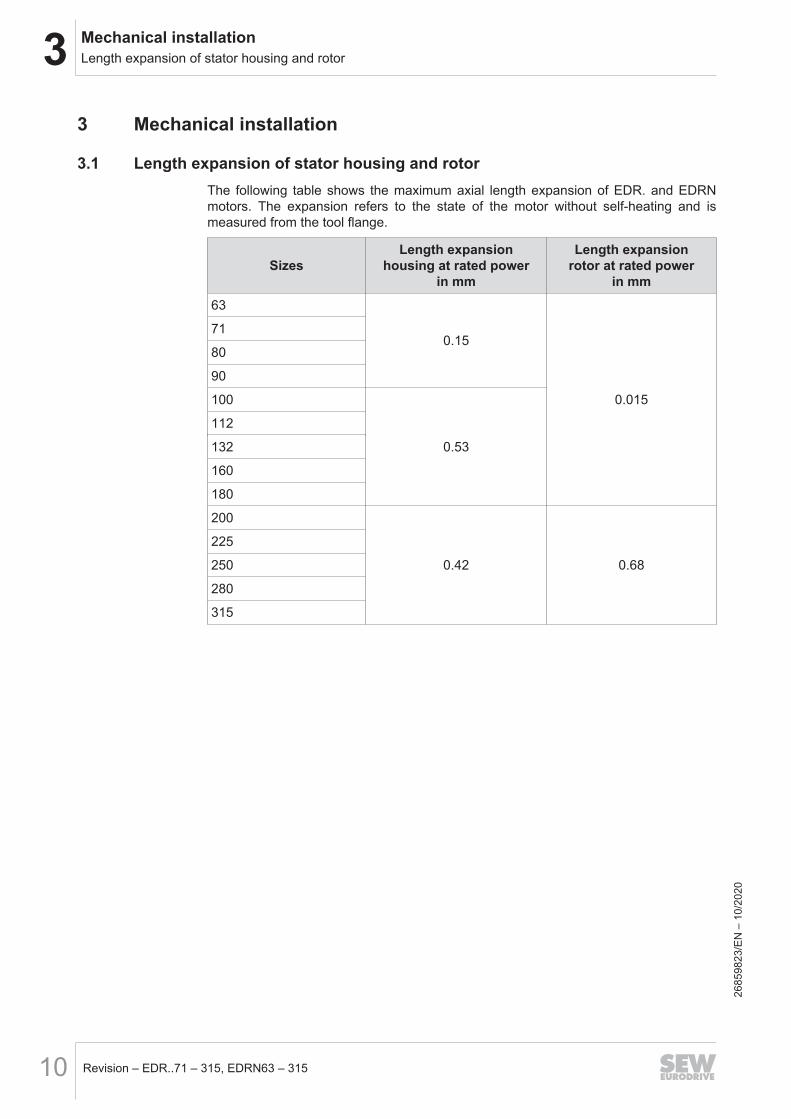
3.1 Length expansion of stator housing and rotorThe following table shows the maximum axial length expansion of EDR. and EDRNmotors. The expansion refers to the state of the motor without self-heating and ismeasured from the tool flange.
SizesLength expansion
housing at rated powerin mm
Length expansionrotor at rated power
in mm63
0.15
0.015
71
80
90
100
0.53
112
132
160
180
200
0.42 0.68
225
250
280
315
2685
9823
/EN
– 1
0/20
20
4Duty types and limit valuesMotor/inverter assignment for motors of design 3G, 3D and 3GD
Revision – EDR..71 – 315, EDRN63 – 315 11
4 Duty types and limit values4.1 Motor/inverter assignment for motors of design 3G, 3D and 3GD
Frequency inverters that have similar values with respect to output current and outputvoltage can also be used. For more information, refer to the standard EN 60079‑15.When selecting and operating the frequency inverters, make sure that the maximuminput voltage of the inverter is 500 V so that the maximum permitted DC link voltage of707 V DC in motor operation is maintained. DC link coupling with 2 or more frequencyinverters is not permitted. Set the PWM frequency of the frequency inverter to at least3 kHz.Combinations for motor voltages other than 230/400 V can be requested fromSEW‑EURODRIVE.
INFORMATIONThe maximum speed values may be lower due to options and connection of a gearunit. Refer to the nameplate for the permitted values.
4.2 Motor/inverter assignment for motors of design 3G-c, 3D-c and 3GD-cFrequency inverters that have similar values with respect to output current and outputvoltage can also be used. For more information, refer to the standard IEC 60079-15for EDR.. and IEC 60079-7 for EDRN.. motors.When selecting and operating the frequency inverters, make sure that the maximuminput voltage of the inverter is 500 V so that the maximum permitted DC link voltage of707 V DC in motor operation is maintained. DC link coupling with 2 or more frequencyinverters is not permitted. Set the PWM frequency of the frequency inverter to at least3 kHz.Combinations for motor voltages other than 230/400 V can be requested fromSEW‑EURODRIVE.
INFORMATIONThe maximum speed values may be lower due to options and connection of a gearunit. Refer to the nameplate for the permitted values.
2685
9823
/EN
– 1
0/20
20


SEW-EURODRIVE—Driving the world
SEW-EURODRIVE GmbH & Co KGErnst-Blickle-Str. 4276646 BRUCHSALGERMANYTel. +49 7251 75-0Fax +49 7251 [email protected]