EDMC Engineering Drawing Requirements
6
EDMC Engineering Drawing Requirements (Produced by Mike Street – 19/10/2008) An engineering drawing is a type of technical drawing, used to fully and clearly define requirements for engineered items, they should be created in accordance with standardised conventions such as BS8888 (superseded BS 308) for layout, dimensioning, interpretation, appearance, size, etc. Its purpose is to accurately and unambiguously capture all the geometric features of a product or a component. The end goal of an engineering drawing is to convey all the required information that will allow any manufacturer worldwide to produce that component. It is easy to accidentally omit various items when creating engineering drawings. Before passing on your work it is recommended that you work through the checklist below for each drawing: General Drawing Requirements 1. Do draw ing v iews conform to relevant convent ions, usually 1 st or 3 rd angle? The EDMC prefers 3 rd angle. 2. Have you used t he m inimum number of views necessary t o accurately show t he informat ion required? 3. Are the views clearly laid in appropriat e positions relat ive t o t he size of paper? 4. Has the tit le block been complet ed, part icularly:- Drawing Title, Number Off, Material, Drawn by, Date, Scale, Drawing Units, Projection (1st or 3rd angle) Geometry Details 1. Check to make sure that there are sufficient dim ensions for t he manufacture of the component. Check t hat positions and sizes of any features, such as holes, are clearly dimensioned. 2. No dimension should appear m ore t han once on t he draw ing, th is is called double dim ensioning. 3. Never dim ension to hidden detail, section view s should be created t o allow dim ensioning of int ernal geometry. 4. Have the dim ensions been laid out in consistent and clear positions?, so they ar e easy t o read, e.g. leader lines for notes should never be aligned horizontal or vertical this can be confused with the component geometry! 5. Have all of t he dim ension lines been construct ed wit h correct ext ension lines and gaps? 6. Have dim ensions relating t o a part icular featur e, such as a hole, been grouped t ogether on one v iew, where possible? 7. Have appropriat e line styles and line weig hts been u sed? E.g. thick lines for com ponent geom etry , thin lines for dimensions, centre lines and hidden detail. 8. Have any surface finish requirem ents been specified? 9. Have any ex plicit t olerance requirem ents been specified? E.g. where par ts fit toget her i.e. bores for bearings, ‘O’ ring grooves and mating components, these should be indicated as upper and lower values. 10. Have required cent re and break lines, etc. been used? all holes / cylindrical featu res need a centre line. 11. Have any general or special notes been added, such as additional gener al tolerances, textur e requirem ents, specification of a particular manufacturing process etc? e.g. welding symbols 12. If sections have been used, do they conform to drawin g conventions? Al l d raw in gs su bm it t ed t o t he EDMC f or man uf act ur e wi l l b e ch eck ed, m aki ng su re t her e is suff icient information contained in the documents before any production can take place!, Every set of engineering drawings must contain at least one assembly drawing unless the manufacture is for a single part. All drawings will be highlighted with the following colours! Green = OK, Red = Amend, Blue = Delete .
-
Upload
usmantayab7174 -
Category
Documents
-
view
217 -
download
0
Transcript of EDMC Engineering Drawing Requirements
8/14/2019 EDMC Engineering Drawing Requirements
http://slidepdf.com/reader/full/edmc-engineering-drawing-requirements 1/5
EDMC Engineering Drawing Requirements(Produced by Mike Street – 19/10/2008)
An engineering drawing is a type of technical drawing, used to fully and clearly define requirements for engineereditems, they should be created in accordance with standardised conventions such as BS8888 (superseded BS 308)for layout, dimensioning, interpretation, appearance, size, etc. Its purpose is to accurately and unambiguouslycapture all the geometric features of a product or a component. The end goal of an engineering drawing is toconvey all the required information that will allow any manufacturer worldwide to produce that component.
It is easy to accidentally omit various items when creating engineering drawings. Before passing on your work it isrecommended that you work through the checklist below for each drawing:
General Drawing Requirements
1. Do drawing views conform to relevant conventions, usually 1 st or 3 rd angle? The EDMC prefers 3 rd angle.
2. Have you used the minimum number of views necessary to accurately show the information required?
3. Are the views clearly laid in appropriate positions relative to the size of paper?
4. Has the title block been completed, particularly:-
Drawing Title, Number Off, Material, Drawn by, Date, Scale, Drawing Units, Projection (1st or 3rd angle)
Geometry Details
1. Check to make sure that there are sufficient dimensions for the manufacture of the component. Check thatpositions and sizes of any features, such as holes, are clearly dimensioned.
2. No dimension should appear more than once on the drawing, this is called double dimensioning.
3. Never dimension to hidden detail, section views should be created to allow dimensioning of internalgeometry.
4. Have the dimensions been laid out in consistent and clear positions?, so they are easy to read, e.g. leaderlines for notes should never be aligned horizontal or vertical this can be confused with the componentgeometry!
5. Have all of the dimension lines been constructed with correct extension lines and gaps?
6. Have dimensions relating to a particular feature, such as a hole, been grouped together on one view,where possible?
7. Have appropriate line styles and line weights been used? E.g. thick lines for component geometry, thin linesfor dimensions, centre lines and hidden detail.
8. Have any surface finish requirements been specified?
9. Have any explicit tolerance requirements been specified? E.g. where parts fit together i.e. bores forbearings, ‘O’ ring grooves and mating components, these should be indicated as upper and lower values.
10. Have required centre and break lines, etc. been used? all holes / cylindrical features need a centre line.
11. Have any general or special notes been added, such as additional general tolerances, texture requirements,specification of a particular manufacturing process etc? e.g. welding symbols
12. If sections have been used, do they conform to drawing conventions?
Al l d rawings submit ted to the EDMC for manufacture wi ll be checked, making sure thereis suff icient information contained in the documents before any production can takeplace!, Every set of engineering drawings must contain at least one assembly drawingunless the manufacture is for a single part.
All drawings will be highlighted with the following colours! Green = OK, Red = Amend, Blue = Delete .

8/14/2019 EDMC Engineering Drawing Requirements
http://slidepdf.com/reader/full/edmc-engineering-drawing-requirements 2/5
TITLE
REVISIONASSEMBLY NUMBERNo OFFSHEET
DESIGNED BY
THE INF ORMAT ION CONT AINED IN THIS DO CUME NT IS THE P ROP ER TY O F THE U NIVER SITY OF S OUTHAMP TON
DO NOT COPY WITHOUT WRITTEN PERMISSION.
ALL DIMENSIONS IN mmUNLESS OTHERWISE STATED
TOLE RANC ES UNLE SSOTHERWISE STATED
DIMS TO 1 DEC PLAC E 0.5mm
DIMS TO 2 DEC PLAC ES 0.25mm
ANGULAR DIMS 0.5mm
+/-
+/-
+/-SCALE
MATERIAL TE XTURE SURFACE FINISH
REMOVE ALL SHARP EDGES
IF IN DOUBT PLEASE ASK
DATE
CUSTOMERPROJECTALL OVER UNLESSOTHERWISE STATED
1.6
DRAWING NUMBER
of
DRAWN BY
COSTMASS
School of Engineering SciencesSouthampton
UNIVERSITY OFDO NOT SCALE
0042-0030042-001
NOSE CONE FRONT
Mike Street
1:101/08/2008
1
MODEL MARINECURRENT TURBINE
Dr LUKE MYERS
A3
A1 1
ALUMINIUM ALLOY6082-T6
Mike Street 0.1 kg
25 MICRONS THICK BLACK SULPHURIC
ACID ANODISED
Title Block – every drawing must contain a title block!
The title block includes a drawing border and various boxes for providing quality, administrative and technicalinformation. The importance of the title block cannot be overlooked as it includes all the information enabling thedrawing to be interpreted, identified and archived.
1. Drawing Title - Description of the part or assembly.
2. Drawing Number - Number of the part or assembly for archiving and cross referencing.
3. Assembly Number - Number of the assembly that the part is referenced to.
4. Number Off - Quantity of component or assemblies to be manufactured.
5. Drawn By - Name of drawing originator.
6. Scale - Identifies the main scale that the drawing is drawn in, e.g. 1:1 =full size, 1:2 =half size.
7. Date - The date the drawing was created or amended on.
8. Drawing Units - Units of the drawing, generally all dimensions in mm.
9. Material - What the item is made of, e.g. Mild steel, Aluminium, if critical include particular grade.
10. Projection System Symbol - The symbol identifying the type of projection, normally 3 rd angle.
11. Surface Finish – The general component surface roughness tolerance, normally 1.6
microns.12. Texture – This is the components final finish e.g. anodised, painted, galvanised etc, or just clean.
13. General Drawing Tolerance – General variation in size unless indicated on individual dimensions.
Example of a Title Block
Paper Sizes
The standard for drawing sheet sizes is the A series, these sizes are as follows.
A0 =1189mm x 841mmA1 =841mm x 591mmA2 =594mm x 420mmA3 =420mm x 297mmA4 =297mm x 210mm
Preferred Scales for Engineering Drawings
1:1, 1:2, 1:5, 1:10, 1:20, 1:50, 1:100

8/14/2019 EDMC Engineering Drawing Requirements
http://slidepdf.com/reader/full/edmc-engineering-drawing-requirements 3/5
1
1
2
2
3
3
4
4
5
5
6
6
7
7
8
8
A A
B B
C C
D D
E E
F F TITLE
REVISIONASSEMBLY NUMBERNoOFFSHEET
DESIGNEDBY
THE INFORMATIONCONTAINEDINTHIS DOCUMENT IS THE PROPERTY OF THE UNIVERSITY OF SOUTHAMPTON
DONOT COPY WITHOUT WRITTENPERMISSION.
ALL DIMENSIONS INmmUNLESS OTHERWISE STATED
TOLERANCES UNLESSOTHERWISE STATED
DIMS TO 1DEC PLACE 0.5mm
DIMS TO 2DEC PLACES 0.25mm
ANGULAR DIMS 0.5mm
+/-
+/-
+/-SCALE
MATERIAL TEXTURE SURFACE FINISH
REMOVE ALL SHARP EDGES
IF INDOUBT PLEASE ASK
DATE
CUSTOMERPROJECT
ALL OVERUNLESSOTHERWISE STATED
1.6
DRAWING NUMBER
of
DRAWNBY
COST
School of Engineering SciencesSouthampton
UNIVERSITY OFMASS
DO NOT SCALE
0042-0000042-000
GENERAL ASSEMBLY OF MODEL MARINECURRENT TURBINE
Mike Street
1:531/07/2008
1
MODEL MARINECURRENT TURBINE
LUKE MYERS
A2
A1 2
Mike Street N/A
A
A
A-A
WATERLINE WATERLINE
1 0 0 0
. 0
400.0STAINLESS STEEL GRADE 3041PLAIN WASHER - M10-11STAINLESS STEEL GRADE 3041HEX NYLON INSERT NUT - M10-10STAINLESS STEEL GRADE 30412HEX SOC CAP HD SCREW - M5 x 20-9NITRILE RUBBER2O' RING 70x2.4-8STAINLESS STEEL GRADE 3041PARALLEL KEY, 5x5x20 LONG TO BS 4235-7VARIOUS2BOWEX TOOTHED DRIVEN COUP LING - ONDRIVES RTK-M-14 (15mmH7 BORE)-6
1SUB ASSEMBLY OF SUPPORT FRAME0042-03951SUB ASSEMBLY OF TOWER0042-02541SUB ASSEMBLY OF GEARBOX0042-01531SUB ASSEMBLY OF NACELLE0042-00821SUB ASSEMBLY OF ROTOR0042-0011
PARTS LISTMATERIALQTYDESCRIPTIONPART NoITEM
X
X ( 1 : 2 )
1
2 3
4
5
6
6
7
1011
88
9
9
2 2 7
. 0
1 0 5 1
. 0
General Assembly Drawing
Assembly drawings are used to:-
1. Name, identify, describe and quantify all of the components making up the finished product.
2. Clearly show how all of the components including sub assemblies and standard parts fit together.
3. Indicate all of the required fasteners and proprietary components such as bearings, motors, seals, etc.
4. Record any special assembly instructions or operation requirements.5. Record any other relevant information.
Detailed dimensions required for manufacture are excluded from assembly drawings. But overall dimensions of theassembled objects are usually indicated; also if certain spatial relationships between parts are important for theproduct to function correctly then these should also be shown on the drawing, e.g. indicating the maximum andminimum clearance between two parts. If there are internal assemblies, sectional views should be used.
Assembly drawings generally should not include hidden lines, thus absence of a hidden line does not imply that nohidden edge exists at that location.
Example of a General Assembly Drawing
Parts Li st
Each part is given a unique number, indicated on the drawing by a circle with the number in it and a leader line
pointing to the part this is called a balloon. The leader line terminates in an arrow if the line touches the edge of thecomponent or in a filled circle if the line terminates inside the part. A table of parts should be added to the drawingto identify each part, the first four items; Item, Part No, Description, and Quantity should be completed for everydistinct part on your drawing. (I.e. the numbers of duplicate parts are recorded in the quantity). The description boxis also used for specifying a manufacturer’s part number when using bought-in parts.
8/14/2019 EDMC Engineering Drawing Requirements
http://slidepdf.com/reader/full/edmc-engineering-drawing-requirements 4/5
1
1
2
2
3
3
4
4
5
5
6
6
7
7
8
8
9
9
10
10
11
11
12
12
A A
B B
C C
D D
E E
F F
G G
H H TITLE
REVISIONASSEMBLY NUMBERNoOFFSHEET
DESIGNEDBY
THE INFORMATIONCONTAINEDIN THIS DOCUMENTIS THE PROPERTY OF THE UNIVERSITY OF SOUTHAMPTON
DO NOTCOPY WITHOUTWRITTENPERMISSION.
ALLDIMENSIONS INmmUNLESS OTHERWISE STATED
TOLERANCES UNLESSOTHERWISE STATED
DIMS TO1DEC PLACE 0.5mm
DIMS TO2 DEC PLACES 0.25mm
ANGULAR DIMS 0.5mm
+/-
+/-
+/-SCALE
M AT ER IAL T EX TUR E S UR FA CE F INI SH
REMOVE ALL SHARP EDGES
IF INDOUBTPLEASE ASK
DATE
CUSTOMERPROJECT
ALLOVER UNLESSOTHERWISE STATED
1.6
DRAWING NUMBER
of
DRAWNBY
COSTMASS
School of Engineering SciencesSouthampton
UNIVERSITY OFDO NOT SCALE
0042-0010042-000
SUB ASSEMBLY OF ROTOR
Mike Street
1:107/08/2008
1
MODELMARINECURRENT TURBINE
LUKE MYERS
A2
A1 2
Mike Street N/A
STAINLESS STEEL GR ADE 3043SPRING WASHER - M8-10STAINLESS STEEL GR ADE 3043PLAIN WASHER - M8-9STAINLESS STEEL GR ADE 3046HEX SOC COUNTERSUNK SCREW M3 x 6-8STAINLESS STEEL GR ADE 3046SPRING PLUNGER M3 - ONDRIVES BPM3SS-7ALUMINIUM ALLOY 6082-T63BLADE0042-0076BRASS3BLADE HUB NUT0042-0065BRASS3BLADE STUB SHAFT0042-0054ALUMINIUM ALLOY 6082-T61NOSE CONE REAR0042-0043ALUMINIUM ALLOY 6082-T61NOSE CONE FRONT0042-0032ALUMINIUM ALLOY 6082-T61HUB0042-0021
PARTS LIST
MATERIALQTYDESCRIPTIONPART NoITEM
A-A
2
8
3
6
4
5
9
10
1
7
NOTES:-
ASSEMBLE ITEMS (4) & (6) USING LOCTITE THEN DRILL/TAP AND ENGRAVE ITEM (4) IN RELATION TO BLADES NEUTRAL AXIS.
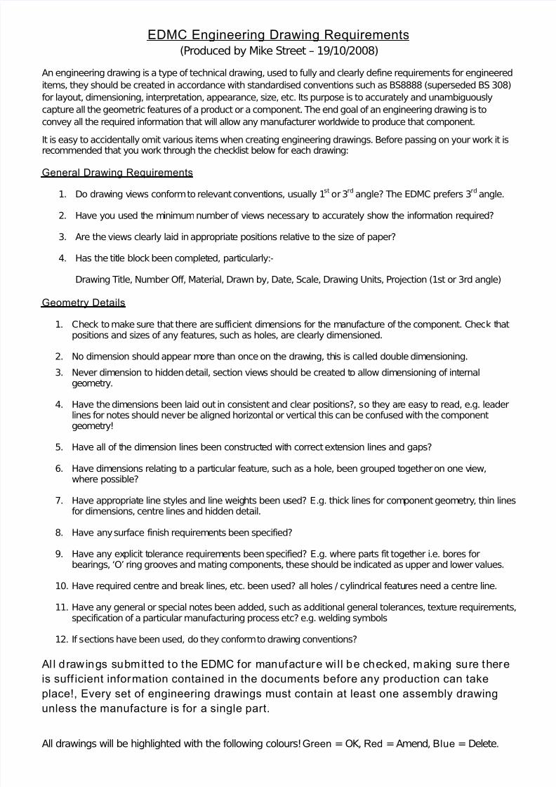
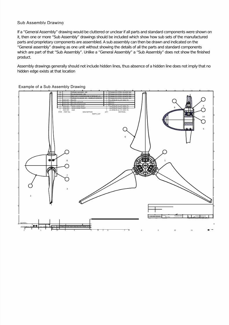
Sub Assembly Drawing
If a “General Assembly” drawing would be cluttered or unclear if all parts and standard components were shown onit, then one or more “Sub Assembly” drawings should be included which show how sub sets of the manufacturedparts and proprietary components are assembled. A sub assembly can then be drawn and indicated on the“General assembly” drawing as one unit without showing the details of all the parts and standard componentswhich are part of that “Sub Assembly”. Unlike a “General Assembly” a “Sub Assembly” does not show the finished
product.
Assembly drawings generally should not include hidden lines, thus absence of a hidden line does not imply that nohidden edge exists at that location
Example of a Sub Assembly Drawing

8/14/2019 EDMC Engineering Drawing Requirements
http://slidepdf.com/reader/full/edmc-engineering-drawing-requirements 5/5
1
1
2
2
3
3
4
4
5
5
6
6
7
7
8
8
9
9
10
10
11
11
12
12
A A
B B
C C
D D
E E
F F
G G
H H
TITLE
REVISIONASSEMBLY NUMBERNo OFFSHEET
DESIGNED BY
THE INFORMATION CONTAINED IN THIS DOCUMENT IS THE PROPERTY OF THE UNIVERSITY OF SOUTHAMPTON
DO NOT COPY WITHOUT WRITTEN PERMISSION.
ALL DIMENSIONS IN mmUNLESS OTHERWISE STATED
TOLERANCES UNLESSOTHERWISE STATED
DIMS TO1 DEC PLACE 0.5mm
DIMS TO2 DEC PLACES 0.25mm
ANGULAR DIMS 0.5mm
+/-
+/-
+/-SCALE
MATERIAL TEXTURE SURFACE FINISH
REMOVE ALL SHARP EDGES
IF IN DOUBT PLEASE ASK
DATE
CUSTOMERPROJECTALL OVER UNLESSOTHERWISE STATED
1.6
DRAWING NUMBER
of
DRAWN BY
COSTMASS
School of Engineering SciencesSouthampton
UNIVERSITY OFDO NOT SCALE
0042-0030042-001
NOSE CONE FRONT
Mike Street
1:101/08/2008
1
MODEL MARINECURRENT TURBINE
LUKE MYERS
A3
A1 1
ALUMINIUM ALLOY6082-T6
Mike Street N/A
A
AA-A
A A
A-A
5.00
2 5
. 0
15.060.065.0
75.0
6 5
. 0 0
3xØ25.50 EQUISPACED
0.5x45°
R6.0
ELLIPTICAL
B
B
B-B
6 1
. 0 3 H 7 (
6 1
. 0 5 5
6 1
. 0 2 5
)
15.0
3 . 0
25MICRONS THICK BLACK SULPHURIC
ACIDANODISED
3x 3.20 CSK AT 90°TO 6.40 EQUISPACED
Detail Drawing
A detail drawing is a drawing of a single component which provides all the information needed to manufacture thepart. This includes the components shape, dimensions, number required, tolerances, material and any specialrequirements, e.g. surface finish, heat treatment, coatings (texture) etc. Normally at least three views (front, top andright or left side) should be shown along with section views were needed, it is also useful to provide an isometricview. Orthographic views should be shown in third angle projection.
1. Use the least views as possible to describe the object fully; this is dependent on the amount of features a component contains.
2. Dimensions should be placed on drawings clearly so that they may be easily read, they should be placed on the face that best describes the feature most clearly.
3. The drawing must include the minimum number of dimensions required to accurately manufacture thecomponent.
4. A dimension should not be stated more than once, unless it aids communication, this is doubledimensioning.
5. It should not be necessary for the engineering technician manufacturing the component to have to calculateany dimensions.
6. Never dimension to hidden detail.
7. All holes should be dimensioned as a diameter using the diameter Ø symbol not as a radius
8. Common dimensions on a single view can be dimensioned using a TYP note meaning typical.
Example of a Detail Drawing