Edition 4 Issue 3 - ACP&D - ppa series brochure.pdf · SOLUTIONS, not just products. Specialists in...
32
High specification cast iron units PPA & PPC series motors Edition 4 Issue 3
Transcript of Edition 4 Issue 3 - ACP&D - ppa series brochure.pdf · SOLUTIONS, not just products. Specialists in...
High specification cast iron units
PPA & PPC series motors
Edition 4 Issue 3

SOLUTIONS, not just productsSpecialists in Electric Motors, Geared Motors & AC Drives
At CMG we off er customised packages to the most demanding industrial markets.
Our success is built on a strong commitment to our customers’ needs and a willingness to fi nd
the best solution possible. We have been in business since 1948 so you can be confi dent our
experience and knowledge is second to none.
With over 650 staff around the globe, our branches extend across Australia, New Zealand,
Asia Pacifi c, South Africa, Europe and the Middle East.
We have the capability to value-add our products through partnerships with leading
international companies whose technical skills are equal to ours, including Gear Motors from
Reggiana Ridutorri and NORD, and AC Drives from VACON. In return we off er these companies
superior technical support that complements their own R&D capabilities.
Our manufacturing facility in Melbourne, Australia, demonstrates our commitment to effi cient
automated manufacturing processes. This facility includes a NATA & ILAC accredited laboratory
which off ers complete design and testing services.
“We specialise in an extensive range of Electric Motors, Geared Motors and AC Drives. O� ering a ‘complete package’ ensures our customers get the most e� cient, cost e� ective solution possible.”
» Electric Motors » Geared Motors » AC Drives
Accreditation No. 14396
Note: Front Cover RAL 2008 Bright Red Orange available in Australia only

CMG Motors | PPA 0811 (edition 4.3.0) 3
PPA & PPC High Efficiency cast iron motorsH Class, IP66, Sizes 80 to 450CMG’s premium high efficiency motor range up to 1000kW features all of your engineers’ specifications as standard.
Our 3-year warranty provides ultimate
peace of mind
Hazardous locations motors, certified to IEC and Australian standards, are also available (page 24)
Meets world market needs and standards – Three phase 380V, 400V, 415V, 440V, 525V, 690V, 1000V & 1100V, 50Hz & 60Hz (page 9) – Australian/British and CENELEC frame allocations
H Class insulation, B class (80°C) temperature rise (page 9)
Totally enclosed IP66 protection standard (page 6)
20 years design life (page 4)
Maintenance without downtime – thru flushing grease relief valve system (page 4)
IEC/EX AUS/EXEx e Zone 1 Ex e Ex nA Zone 2 (formerly Ex n) Ex nEx tD (formerly DIP) DIP
Note: Features vary according to frame size.
Designed and built for arduous environments and mining specifications
Custom designs from 100 to 1100V, 40 to 60Hz available (page 9)
Sensors and Protection built in – Thermistors – SPM vibration stud – Anti-condensation heaters – Additional external earth screw
Low noise low vibration design (page 8)
Cast iron fan, steel fan cover, and stainless steel nameplates (page 5)
Standard 2-pack epoxy or customized surface finishes (page 5)
Eff 1 / MEPS efficiency (page 4)
Oversized and reversible terminal box (page 6)
Full cast iron construction (page 5)

4 CMG Motors | PPA 0811 (edition 4.3.0)
IntroductionThis catalogue details CMG’s premium range of PPA & PPC series motors. PPA & PPC motors are three phase squirrel cage TEFC (IC411), available in frame sizes 80 to 450, and have been designed and manufactured in accordance with AS/NZS1359 (IEC 60034 & IEC 60072). ‘PPA’ is commonly used to refer to both PPA and PPC ranges.
High specification design
Electric motors are installed in a wide range of conditions from sub zero temperatures to tropical environments and dusty deserts. The PPA range, with its rugged cast iron enclosure, is designed to suit these harsh conditions and provide both high operational reliability and low operating costs.
20 year design life
All motors in the PPA range are manufactured with Class H insulation. They are designed to operate with a temperature rise of 80°C or less (Class B), and provide a thermal reserve in excess of 45°C when operating in a 40°C ambient. This ample thermal reserve means the PPA has a winding design life of 20 years.
Ultimate protection
The entire PPA range has an enclosure protection rating of IP66. The windings are tropic protected and oil resistant with the motors being weather protected as standard.
High efficiencyThe PPA range of motors comply to AS/NZS 1359.5.2004 for standard efficiency motors. PPA efficiencies are also in line with European EFF1 and correspond to IE2 levels (High Efficiency) of IEC 60034-30
Thru-flushing grease relief valve
The pressure grease relief valve, incorporating a V–ring seal, eliminates downtime by enabling relubrication of the bearings without stopping the motor.
A complete selection
PPA series motors can be designed for use on 100 to 1100V systems and for all common world frequencies including 40Hz, 50Hz and 60Hz. The most common power supplies are 380V, 400V, 415V, 440V, 525V, 690V, 1000V and 1100V. Customer specified variations on these standards
are readily available.
Standards and specifications
The main dimensions and rated outputs of PPA motors generally conform to IEC 60072 and AS/NZS1359 (Australian/British kW-frame size allocation table).The PPC range has a similar specification to that of the PPA range with the kW/frame allocation being taken from the CENELEC table. (The term ‘PPC’ is used only where the frame allocation is different from the PPA.)
CMG Technology offer full load testing in their NATA and ILAC accredited laboratory on all motors within the PPA and PPC ranges. Speed-torque / current / efficiency curves are available upon request.
Hazardous location certification
PPA motors are certified for use in hazardous locations as per IEC and Australian standards. IEC certificate number is IEC Ex TSA 06.0035X. Australian certificate numbers are as below:
Location Protection Ambient temp. Certificate
Zone 1 Ex e II T3 50°C AUS Ex 3852XZone 2 Ex nA II T3 60°C AUS Ex 3853X
Ex tD A21 TA T4 50°C AUS Ex 3853X
Note: Ex tD was formerly known as DIP.
Product code specificationWhen placing an order the motor product code should be specified. The product code of the motor is composed in accordance with the following example:
M 3 2 0 0 1 5 0 3 P P A E / 4 0 51 2 3 4-8 9 10 - 12 13... Suffix
Position 1 M = metric frame size
Position 2Phase3 = three phase single
speed motor
Position 3Number of poles2 = 2 poles 4 = 4 poles6 = 6 poles 8 = 8 polesA = 10 poles C = 12 poles
Positions 4 to 8Rated power output (kW x 100)
Position 9Mounting arrangement1 = V1 3 = B34 = B3/B5 5 = B5
Positions 10 to 12SeriesPPA = PPA series motorsPPC = PPC series motors
Position 13...*Series variationBlank = StandardE = Zone 1 Ex eF = Flying leads N = Zone 2 Ex nAD = Ex tD (DIP)L = LHS terminal boxR = Airstream rated
* Multiple letters indicate multiple variation.
SuffixWinding design Blank = 415V / 50 Hz/385 = 380V / 50 Hz/405 = 400V / 50 Hz/445 = 440V / 50 Hz/525 = 525V / 50 Hz/695 = 690V / 50 Hz/A05 = 1000V / 50 Hz/B05 = 1100V / 50 Hz/386 = 380V / 60 Hz/406 = 400V / 60 Hz

CMG Motors | PPA 0811 (edition 4.3.0) 5
Mechanical designMountingsCMG PPA motors are available in the mounting arrangements shown below. For all other mounting arrangements please contact CMG directly.
* Most common mounting arrangements
Materials and construction
GeneralFrames 80-450 Cast iron construction, one pieceEndshields Cast iron constructionTerminal box Cast iron constructionFan Bi-directional cast iron or fabricated steelFan Cowl Fabricated steel (heavy gauge)Fasteners Corrosion protected (stainless optional)
Endshields
Endshields are manufactured from close-grained pearlite grey cast iron having a 250MPa tensile strength. The endshields are adequately ribbed to provide cooling to the area around the bearing. Their shallow design ensures they remain rigid under the stresses of starting and running, and are designed to withstand the radial and axial forces encountered during most applications.
Stator frame
Stator frames are manufactured from close-grained pearlitic grey cast iron having a 250MPa tensile strength. Their one piece design ensures the stator remains rigid under all starting and running conditions. The ribs are designed to dissipate the optimum amount of heat with the lowest airflow over the motor. This helps to ensure that windage noise is minimized. Adequate spacing between ribs is maintained to lessen the possibility of blockage due to the build up of dirt.
Shaft
Shafts are manufactured from high quality steel and adequately proportioned to provide strength and rigidity in operation. Bearing journals are ground to ensure an accurate bearing fit and positioning. Keys are provided with each motor.
Shaft extension run out, concentricity, and perpendicularity to the face of standard flange mount motors comply with normal grade tolerance as specified in IEC 60072 and AS/NZS1359. Precision grade tolerance is available upon special order. Non-standard dimensions and shaft materials are available on request.
Rotor
Rugged one piece rotor cages are die cast aluminium. After fitting the rotor core to the shaft the rotor assembly is dynamically balanced to G1 limits for smooth operation.
Finish
All castings and steel parts are primed with a 2-pack epoxy coating, followed by a top coat of 2-pack epoxy to the customer’s color specification.
Standard colours are as follows: RAL 5010 Gentian Blue (except Australia) • RAL 2008 Bright Red Orange (Australia only)• RAL 5019 Capri Blue (1000V motors only)•
Special paint systems can be provided to accommodate stringent requirements for motors in corrosive environments, selected to resist substances such as acid, salt water and extreme climatic conditions.
Stainless steel nameplates
The motor nameplate is manufactured from stainless steel, with markings engraved, not printed, to provide permanency. Thermistor and heater labels are all manufactured from stainless steel.
280

6 CMG Motors | PPA 0811 (edition 4.3.0)
Protection
For vertically mounted motors
The PPA series motor can be mounted vertically shaft up without the need for additional covers or protection. When mounted vertically shaft down protective hoods are available upon request.
Solar radiation
High solar radiation from exposure to direct sunlight may result in an adverse total motor temperature. In these circumstances motors should be screened with adequate and appropriate sunshades without inhibiting airflow.
Degree of protection
Standard levels of enclosure protection for all PPA series motors is IP66 for both motor and terminal box. Sintered bronze porous drain plugs are fitted to the lowest point of the motor enclosure, as standard.
IP66 enclosure protection means dust tight (no ingress of dusts), and protection against heavy seas (water from heavy seas or water projected in powerful jets shall not enter the enclosure in harmful quantities).
Enclosure designations comply with IEC 60529 and AS60529. The enclosure protection rating required depends upon the environmental and operational conditions in which the motor is to operate.
Additional earth terminalAdditional to the earth terminal fitted within the main terminal box an external earth, for grounding of the frame, is fitted on the motor foot for frame sizes 250 and above. (Optional on smaller sizes.)
Terminal box
Cast iron diagonally split terminal boxes are provided on all PPA motors. They are located on the centre line of the stator allowing easy change of the terminal box from the right hand side to the left (except 450 frame, which must be specifically ordered). Refer to the “Modification, variations and optional extras” section on page 27.
The terminal box is designed oversize to accommodate fitting of larger than standard cables used to minimise voltage drop over long cable runs. The box’s ample dimensions also allow aluminium cables to be terminated using bi-metal lugs.
A removable gland plate is fitted to all terminal boxes, frame 225 and above (smaller frames optional). For frames 80 to 315 the gland entry is drilled and tapped with standard metric threads as per the accompanying table. Motor frames 355 and above are fitted with undrilled ferrous gland plates. (Non ferrous optional). The terminal box is supplied with the conduit entry facing downward and can be rotated through 360° in 90° increments.
Conduit entries
Motor frame
Standard Alternative (South Africa std)
Number of entries
Entry / pitch
Number of entries
Entry / pitch
80 2 M20 x 1.5 2 M20 x 1.590 2 M20 x 1.5 2 M20 x 1.5100 2 M20 x 1.5 2 M20 x 1.5112 2 M25 x 1.5 2 M25 x 1.5 132 2 M25 x 1.5 2 M25 x 1.5160 1 M50 x 1.5 2 M25 x 1.5180 1 M50 x 1.5 2 M32 x 1.5200 1 M50 x 1.5 2 M32 x 1.5225 1 M63 x 1.5 2 M40 x 1.5250 1 M63 x1.5 2 M40 x 1.5280 1 M63 x 1.5 2 M50 x 1.5315 1 M63 x 1.5 2 M63 x 1.5355 Nil BGP Nil BGP400 Nil BGP Nil BGP450 Nil BGP Nil BGP
BGP = Blank Gland Plate.
Nitrile gaskets are fitted between all mating surfaces to ensure that the IP66 degree of protection is maintained.
During transportation and storage the conduit entry hole is fitted with a removable plug to limit the ingress of moisture.
CoolingPPA motors are fitted with a low noise bi-directional cast iron or fabricated steel fan. The fan, with its radial blades, and the fan cover of a conical shape, is designed to minimise turbulence within the fan housing and allow smooth airflow.
In most instances the fan and cover are designed to eliminate the need for special acoustic attenuation required to meet stringent noise level standards.
For special applications such as low speed, operation through a VVVF drive, or frequent starting and stopping, a separately driven cooling fan is available as an optional extra. See VVVF Drive Kit A in the “Modification, variations and optional extras” section on page 27.

CMG Motors | PPA 0811 (edition 4.3.0) 7
Cooling air flows from the non-drive-end to the drive end. When the motor is installed care should be taken not to impede the airflow into the motor cowl.
As a guide the following minimum dimension BL should be adopted:
Motor frame
BL [ mm ]
80 - 132 40160 - 200 60225 - 450 80
Bearings and lubrication
Bearings
As standard all PPA motors have high quality bearings made from vacuum degassed steel. The standard bearings in the range are selected to provide long operational life, quiet running, and high load carrying capacity.
4, 6 and 8 pole motors up to 280 frame, and all 2 pole motors, as standard are fitted with high quality deep groove ball bearings. 4, 6 and 8 pole motors 315 frame and above are fitted with cylindrical roller bearings on the drive end.
Motor frame DE Standard DE Optional NDE Standard
80 6204ZZ 6204ZZ90 6205ZZ 6205ZZ100 6206ZZ 6206ZZ112 6306 NU306 6306132 6308 NU308 6308160 6309 NU309 6309180 6310 NU310 6310200 6312 NU312 6312225 6313 NU313 6313250 - 2 6313 6313250 - 4, 6, 8 6315 NU315 6313280 - 2 6314 6314280 - 4, 6, 8 6317 NU317 6314315 - 2 6316 6316315 - 4, 6, 8 NU318 6316355 - 2 6318 6318355 - 4, 6 , 8 NU324 6324400 - 2 6318 6318400 - 4, 6, 8 NU326 6326450 - 4, 6, 8 NU328 6326
In standard arrangement, non-drive end bearing is locked to prevent axial movement.
Drive and non-drive bearing housings
PPA motors frames 80 to 100 have sealed non-regreasable bearing housings. The bearings are prelubricated with a lithium based grease. All motors of frame 112 and above are fitted with a thru-flushing pressure grease relief valve incorporating a V-ring seal which allows the bearing to be relubricated without stopping the motor.
Optional roller bearings
For motor frames 112 to 280, in applications with increased radial force, ball bearings can be substituted for cylindrical roller bearings at the drive end, in accordance with the bearings table on this page.
Shaft locking clamps
All motors within the PPA range 200 frame and above are fitted with a substantial shaft-locking clamp to help prevent false brinnelling in transport. The motors should always be transported or stored with this clamp fitted and tensioned to avoid bearing damage.
Once the motor has reached its final destination and is ready for installation the shaft-locking clamp must be removed before the motor is run no-load to confirm that the bearings are in good condition.
After this initial run normal installation can continue with additions of pulleys or couplings.
Lubrication
Standard bearings are lubricated with a lithium based rolling contact bearing grease, having an R3 consistency and suitable for operation within the cooling air temperature range of -20°C to +55°C. For operation outside this temperature range special lubricants are required.
Special lubricants or additional maintenance may also be required in cases where motors are exposed to a comparatively high degree of pollution, high humidity, increased or changed bearing loads, or prolonged continuous operation. For details of grease quantities, re-lubrication intervals, and recommended grease types refer to the “Installation and maintenance” instructions on page 28.

8 CMG Motors | PPA 0811 (edition 4.3.0)
Balancing, vibration and noise
Balancing
PPA motors have their rotor balanced separately to the external cooling fan so that the fan can be removed or changed without altering the balance of the rotor.
All rotors are balanced with a half key to fine tolerances(G1).
Pulleys or couplings used with motors must be appropriately balanced.
Vibration
PPA series motors fall within the limits of vibration severity as set out in IEC 60034-14, which are listed below. Values relate to rotating machinery measured in soft suspension.
Vibration severity limit
Motor frame
Maximum RMS vibration velocity [ mm/s ]
80 1.690 1.6100 1.6112 1.6132 1.6160 2.2180 2.2200 2.2225 2.2250 2.2280 2.2315 2.8355 2.8400 2.8450 2.8
Vibration sensors
Provision for fitting vibration sensors for condition monitoring is standard on all motors of frame size 250 and above (optional on smaller sizes).
Vibration levels can be checked with an SPM monitor, or its equivalent, when the motor is new and on a regular basis, usually at the same time as re-greasing. This ensures optimum bearing life is achieved and bearing failures avoided.
Low noise
The PPA fan cooling system is designed to achieve the required air flow with minimum losses. This enables the fan to cool the motor whilst keeping noise levels to a minimum.
The table below shows the overall sound pressure levels of PPA motors at 1 metre (no load).
Sound pressure level
kW
Sound pressure level dB(A) at 1 metre
3000 r/min 1500 r/min 1000 r/min 750 r/min
0.37 60 58 54 510.55 60 58 54 510.75 60 58 58 511.1 60 62 60 541.5 60 62 63 542.2 60 62 63 633 63 62 67 634 63 62 67 635.5 74 62 67 637.5 74 62 67 6311 74 72 67 6315 77 72 67 6818.5 77 72 71 6822 77 72 71 6830 79 72 72 6837 80 73 72 6845 80 73 72 6855 80 73 72 6875 80 74 73 7390 82 75 74 73110 82 76 75 73132 82 78 77 73150 83 78 77 73185 84 79 77 74200 85 79 77 74220 87 81 77 74250 89 83 77 74280 90 83 77 74315 90 84 77 74355 90 85 78 74400 90 88 78450 95 88 78500 95 89 78560 95 90 85630 90 85710 91 85800 93 85900 931000 93
Alternate devices are available for noise reduction where very low levels are specified. These include uni-directional fans, separately driven cooling fans, inlet attenuation, and full motor attenuation.

CMG Motors | PPA 0811 (edition 4.3.0) 9
Electrical designOperating parametersStandard PPA series motors have the design and operating parameters listed below. Performance data is based on this standard. Three phase See voltage and frequency belowAmbient cooling air Temperature 40°C
Altitude up to 1000mDuty cycle S1 (continuous)Rotation Refer table on page 10.
Any variation from these operating parameters should be examined and performance data altered in accordance with the information provided in this section.
Voltage and frequencyPPA motors are manufactured for various rated power supplies. Standard rated supplies include:
380V 50Hz 1000V 50Hz400V 50Hz 1100V 50Hz415V 50Hz 380V 60Hz525V 50Hz 440V 60Hz690V 50Hz
Motors can be manufactured for any supply from 100 to 1100V and frequencies other than 50Hz or 60Hz.
PPA motors are designed to operate on VVVF drives and will provide constant torque on the condition that the voltage/frequency ratio remains constant.
PPA motors may operate when connected to other non-standard voltages and frequencies. Rated performance data values should be multiplied by the factors in the table below to give more realistic operating data values which, if used, will reduce additional motor temperature rise.
Apply these factors to motors rated at 415V 50Hz but operated on other supplies:
Supply [ Volts / Hz ]
Rated speed
Rated power
Rated current IN
Rated torque TN
Locked rotor torque TL
Break down torque TB
380/50 1.00 0.95 1.00 0.95 0.83 0.83400/50 1.00 1.00 1.00 1.00 0.93 0.93415/50 1.00 1.00 1.00 1.00 1.00 1.00440/50 1.00 1.00 1.00 1.00 1.10 1.10415/60 1.20 1.00 1.00 0.83 0.69 0.69440/60 1.20 1.05 1.00 0.87 0.77 0.77460/60 1.20 1.10 1.00 0.91 0.85 0.85480/60 1.20 1.15 1.00 0.96 0.92 0.92
For critical applications data should be confirmed.
The performance data for motors with other supply ratings is the same as that provided on pages 12, 14, 16 & 18 for 415V motors, except for the currents which are presented on pages 13, 15, 17 & 19.
Temperature and altitudeRated output power specified in the performance data tables apply for standard ambient conditions of 40°C up to 1000m above sea level. Where temperature or altitude differ from the standard, multiplication factors in the table below should be used.
Ambient temperature
Temperature factor
Altitude above sea level
Altitude factor
30°C 1.06 1000m 1.0035°C 1.03 1500m 0.9840°C 1.00 2000m 0.9445°C 0.97 2500m 0.9150°C 0.93 3000m 0.8755°C 0.88 3500m 0.8260°C 0.82 4000m 0.77
Effective power
=Rated power
xTemperature factor
xAltitude factor
InsulationPPA series motors are wound with H Class insulation and winding designs limit the temperature rise to 80K (unless otherwise noted) for which B Class insulation would normally be sufficient. The use of H Class insulation provides an additional safety margin of 45K, as shown inthe accompanying table, together with a design life in excess of 20 years.
Due to their conservative design many sizes in the PPA range of motors have temperature rises considerably less than 80K and therefore provide even greater safety margins.
Insulation class
B F H
Max. permissible winding temp. (°C) 130 155 180Less ambient temp. (°C) -40 -40 -40Less hotspot allowance (K) -10 -10 -15Equals max. permissible temp. rise (K) 80 105 125Less max. design temp. rise (K) -80 -80 -80Equals min. safety margin (K) - 25 45
DutyPPA motors are supplied suitable for S1 operation (continuous operation under rated load). To determine the correct motor size for duty cycles other than S1 please contact CMG with the following information:
• Type and frequency of switching (short time, intermittent, periodic, high inertia, braking)
• Load torque variation during motor acceleration and braking (in graphical form)
• Moment of inertia of the load on the motor shaft• Type of braking (e.g. mechanical, electrical through
phase reversal or DC injection).

10 CMG Motors | PPA 0811 (edition 4.3.0)
RotationFor clockwise rotation (standard), viewed from drive end, standard three phase PPA motor terminal markings coincide with the sequence of the phase line conductors. For counter-clockwise rotation, viewed from drive end, two of the line conductors have to be reversed. This is made clear in the accompanying table.
Non-standard motors, with the terminal box located on the left when viewed from drive end, have a counter-clockwise rotation for coinciding markings, and reversing two of the line conductors will reverse the rotation to clockwise.
Terminal box location (viewed from D-end)
Sequential connection of L1, L2 and L3
Direction of rotation
Right U1 V1 W1 ClockwiseV1 U1 W1 Counter-clockwise
Left V1 U1 W1 ClockwiseU1 V1 W1 Counter-clockwise
Connection and startingPPA motors are suitable for use with both rated voltage DOL operation and rated voltage three phase variable frequency drives. 3kW and below can also be used with 220-250V three phase variable frequency drives when connected in Delta.
Alternatively, 380-415V, 4kW to 630kW Delta connected motors can be operated DOL, or in the Star configuration with a 690V supply or with a 690V variable frequency drive. When used with a VVVF drive they must be supplied with an output reactor to protect the winding insulation. These motors are also suitable for Star/Delta starting. For motors 710kW and above the standard connection is Delta with a rated voltage of 690V.
Electronic soft starters and VVVF drives are available through CMG Drives Division, and are best supplied together with the motor.
Electronic soft starters
Through the use of an electronic soft starter, which controls parameters such as current and voltage, the starting sequence can be totally controlled. The starter can be programmed to limit the amount of starting current where, by limiting the rate of the current increase, the startup time can be extended.
VVVF Drives
The PPA motor performs excellently without cogging at low speed when operating in conjunction with a VVVF (Variable Voltage Variable Frequency) Drive. Variable voltage variable frequency (VVVF) drives are primarily recognized for their ability to manipulate power from a constant 3 phase 50/60Hz supply converting it to variable voltage and variable frequency power. This enables the speed of the
motor to be matched to its load in a flexible and energy efficient manner. The only way of producing starting torque equal to full load torque with full load current is by using VVVF drives. The functionally flexible VVVF drive is also commonly used to reduce energy consumption on fans, pumps and compressors and offer a simple and repeatable method of changing speeds or flow rates.
The standard insulation provided on PPA motors can accept a rise time of 3000V/µs and a peak voltage of 2600V. To ensure that this parameter is not exceeded care should be taken in the selection of the VVVF drive and, where necessary, suitable output voltage filters should be used. All drives supplied by the CMG Drives Division will comply with this parameter.
For operation below 30Hz motor cooling fan efficiency drops significantly. Hence, in the constant torque applications, a separately driven cooling fan should be fitted to provide sufficient cooling of the motor.
For operation between 30Hz and 50Hz speed range the motor is capable of delivering full rated torque with its standard fan.
For operation above 50Hz, all PPA motors are capable of delivering constant rated power up to 60Hz. However, most of these motors are suitable to run and deliver constant power at much higher frequencies than 60Hz to a maximum of 100Hz. In the case of applications between 60Hz and 100Hz please contact CMG for advice on suitability.
The PPA range of motors will operate without modification on VVVF drives however under certain conditions additional features should be considered (see EDM Concerns below). The graph below shows the PPA motors’ loadability with a frequency converter.
EDM concerns
Capacitive voltages in the rotor can be generated due to an effect caused by harmonics in the waveform causing voltage discharge to earth through the bearings. This discharge results in etching of the bearing running surfaces. This effect is known as Electrical Discharge Machining (EDM). It can be controlled with the fitment of appropriate filters to the drive.
To further reduce the effect of EDM, an insulated non drive bearing can be used. CMG recommends the use of insulated bearings for all motors 315 frame and above.
Speed
Cur
rent
Soft Starter
DOL
Frequency (Hz)
Torq
ue (%
of r
ated
)
0 5 10 15 20 25 30 35 40 45 50 55 60 65 70 75
110100
908070605040302010
0

CMG Motors | PPA 0811 (edition 4.3.0) 11
Thermal protectionResistance Temperature Detectors (RTDs) and additional thermistors can be installed in both the windings and the bearings.
Thermistors
PPA motors are fitted, as standard, with one set (3) of PTC thermistors, selected for a tripping temperature of 145°C. These thermo-variable resistors have a positive temperature coefficient and are fitted one per phase in the motor windings.
Additional sets of thermistors, if required for such functions as alarm or spare, can be fitted with the same or alternate tripping temperatures.
Frames 80 to 132: the thermistors are terminated within the main terminal box. Frames 160 and above: the thermistors are terminated in the right hand auxiliary terminal box.
RTDs
An additional method of monitoring temperature is to fit 3 wire PT100 Resistance Temperature Detectors (RTDs). RTDs are terminated in an auxiliary terminal box affixed to the main terminal box. These devices have a linear temperature / resistance gradient and can be used in conjunction with electronic control equipment e.g. PLC’s. Winding RTDs are fitted as standard in 315 frame, optional in smaller frames.
Anti-condensation heatersPPA motors frames 250 and above are fitted with anti-condensation heaters (optional on smaller sizes). These heaters are connected during manufacture for 220 - 250V operation and can be supplied connected for 380 - 440V operation against special order. They are terminated in the left hand auxiliary terminal box.
Speed at partial loadsThe relationship between motor speed and degree of loading in a PPA motor is approximately linear up to the rated load.
nN = full load speednS = synchronous speedP/PN = partial load factor
Current at partial loadsCurrent at partial loads can be calculated using the following formula:
IX = partial load current (amps)PoutX = partial load (kW)UN = full load voltagecosφX = partial load power factorηX = partial load efficiency (%)
Torque characteristicsTypical characteristics of torque behaviour relative to speed are shown in the torque speed curve example below.
PPA motors all exceed the minimum starting torque requirements for Design N (Normal torque) as specified in IEC 60034-12 and AS1359.41.
Full load torque can be calculated with the following formula:
Where:TN = full load torque (Nm)PN = ful load power (kW)nN = full load speed (r/min)TL = locked rotor torqueTU = pull-up torqueTB = break down torquenS = synchronous speed
0 nN nS Speed
Torq
ue
Load Torque
T U
T L
T N
T B
5
XXN
XX 10
cosU3PoutI
N
NN n
P9550T
Spee
d
0.25 0.50 0.75 1.00 Load P/PN
nS
nN
0

12 CMG Motors | PPA 0811 (edition 4.3.0)
PPA series, Three phase, 415V 50HzIP66, H class insulation, B class temperature rise
Performance data
kW Motor frame Speed [ r/min ]
Efficiency [ % ]at % full load
Power factor [ cos φ ]at % full load Current
tE 1)
time [ sec ]
Torque
Moment of InertiaJ=¼GD2[ kg•m² ]
Weight of foot mount motor [ kg ]
100 75 50 100 75 50
Full load IN [ A ]
Locked rotor IL/IN
Full load TN [ Nm ]
Locked rotor TL/TN
Pull up TU/TN
Break downTB/TN
3000 r/min = 2 poles0.55 80A - 19 2880 80.7 80.3 77.1 0.85 0.79 0.68 1.2 7.9 - 1.8 2.7 2.2 3.3 0.00020 200.75 80B - 19 2885 81.8 81.6 79.1 0.85 0.79 0.68 1.5 7.0 22 2.5 2.7 2.4 3.2 0.00022 211.1 80C - 19 2880 83.8 84.2 82.4 0.86 0.80 0.69 2.2 8.0 15 3.6 2.9 2.5 3.3 0.00023 241.5 90S - 24 2890 86.3 86.6 84.9 0.88 0.84 0.75 2.8 8.3 25 5.0 2.7 2.2 3.0 0.0003 292.2 90L - 24 2880 87.1 88.0 87.5 0.87 0.84 0.76 4.1 7.8 15 7.3 2.8 2.2 2.9 0.00035 333 100L - 28 2910 88.2 88.3 86.8 0.89 0.85 0.75 5.4 7.9 20 9.8 2.2 2.0 3.3 0.00073 454 112M - 28 2920 87.6 87.6 87.2 0.88 0.86 0.81 7.3 9.0 10 13.1 2.6 1.8 3.6 0.0014 555.5 132SA - 38 2940 89.3 88.8 86.8 0.89 0.86 0.78 9.6 7.8 30 17.9 2.3 1.7 3.6 0.0030 847.5 132SB - 38 2940 90.3 90.3 89.0 0.90 0.87 0.81 12.8 7.6 12 24.4 2.2 1.8 3.4 0.0032 8811 160MA - 42 2930 90.6 90.5 88.9 0.91 0.90 0.83 18.5 7.0 20 35.9 2.0 1.4 2.5 0.054 13915 160MB - 42 2940 91.3 91.1 89.8 0.90 0.89 0.84 25.5 7.4 9 48.7 2.1 1.5 2.5 0.056 14418.5 160L - 42 2940 91.9 92.0 90.9 0.92 0.91 0.86 30.5 7.5 7 60.1 2.7 1.7 2.9 0.066 16322 180M - 48 2945 92.2 92.1 90.6 0.92 0.90 0.82 36.5 7.9 11 71.3 3.3 1.8 3.4 0.094 21730 200LA - 55 2950 92.9 92.7 91.4 0.90 0.88 0.82 50 8.0 8 97.1 2.4 1.7 2.9 0.167 28237 200LB - 55 2955 93.3 93.2 92.2 0.91 0.89 0.84 61 7.8 6 120 2.7 1.7 2.9 0.174 29045 225M - 55 2975 93.7 93.0 91.4 0.94 0.87 0.84 72 8.0 6 144 2.7 1.9 3.1 0.30 38255 250S - 60 2975 94.3 94.1 92.9 0.89 0.88 0.83 91 7.2 6 177 2.2 1.6 2.8 0.38 43775 250M - 60 2985 94.9 94.5 93.1 0.91 0.89 0.82 122 7.1 5 240 3.0 1.9 3.1 0.47 50690 280S - 65 2972 95.3 95.2 94.5 0.90 0.89 0.85 146 6.8 6 289 3.0 2.4 3.2 0.79 645110 280M - 65 2976 95.1 94.8 93.8 0.92 0.92 0.91 175 7.7 6 353 3.3 2.1 3.4 0.93 723132 315S - 65 2982 95.6 95.2 94.1 0.93 0.91 0.87 207 6.4 8 423 1.9 1.7 2.9 1.40 1135150 315M - 65 2979 95.6 95.2 94.2 0.92 0.91 0.88 237 6.4 7 481 2.0 1.7 2.9 1.55 1185185 315L - 65 2979 95.8 95.4 94.5 0.90 0.88 0.84 298 7.5 6 593 2.1 1.6 2.9 1.73 1240200 315LXA - 65 2980 95.9 95.7 94.7 0.93 0.92 0.90 312 6.3 6 641 2.0 1.5 3.0 1.81 1280220 315LXB - 65 2978 95.7 95.4 94.3 0.92 0.91 0.87 348 7.5 6 706 2.7 1.5 2.6 2.00 1320250 355LA - 85 2979 95.6 95.2 94.0 0.87 0.85 0.81 416 7.4 7 801 2.1 1.4 2.7 4.46 1630280 355LB - 85 2979 96.0 95.8 94.6 0.90 0.89 0.86 452 7.2 7 898 2.0 1.6 2.9 4.87 1700315 355LC - 85 2979 96.2 95.9 95.0 0.91 0.91 0.89 501 6.2 7 1010 1.9 1.6 2.8 4.90 1750355 355LX - 85 2986 96.7 96.5 95.7 0.92 0.91 0.87 557 7.0 6 1135 2.2 1.9 3.2 5.46 2245400 355LX - 85 2985 96.4 96.2 96.0 0.91 0.89 0.87 635 6.2 7 1280 1.8 1.4 2.5 5.60 24204502) 400LA - 85 2980 96.5 96.6 96.4 0.90 0.89 0.86 721 5.9 6 1442 1.8 1.4 2.5 9.47 27005002) 400LX - 85 2985 96.6 96.8 96.5 0.91 0.89 0.86 791 6.9 6 1600 2.0 1.7 2.9 11.39 30705602) 400LX - 85 2980 96.7 96.8 96.6 0.91 0.91 0.89 885 6.2 7 1795 1.9 1.5 2.6 11.60 3170
PPC series 415V 50Hz45 225M - 55 2975 93.7 93.0 91.4 0.94 0.87 0.84 72 9.5 6 144 2.7 1.9 3.1 0.30 38255 250M - 60 2975 94.3 94.1 92.9 0.89 0.88 0.83 91 6.5 8 177 2.2 1.6 2.8 0.38 43775 280S - 65 2975 94.6 94.8 94.5 0.90 0.89 0.85 123 7.9 7 241 3.0 2.1 3.1 0.67 55090 280M - 65 2972 95.3 95.2 94.5 0.90 0.89 0.85 146 7.8 6 289 3.0 2.4 3.2 0.79 645110 315S - 65 2981 95.1 94.5 93.0 0.91 0.89 0.85 178 6.7 - 352 2.0 1.7 3.1 1.15 965132 315MA - 65 2982 95.6 95.2 94.1 0.93 0.91 0.87 207 6.5 9 423 1.9 1.7 2.9 1.40 11351603) 315MB - 65 2977 95.6 95.2 94.2 0.92 0.91 0.88 253 6.0 - 513 1.9 1.6 2.7 1.55 1185200 355LA - 80 2980 95.5 95.6 95.4 0.89 0.88 0.85 328 6.6 7 641 2.0 1.7 2.7 3.78 1300225 355LB - 80 2981 96.4 96.3 95.4 0.93 0.92 0.86 349 6.8 - 721 1.9 1.5 3.1 4.11 1535250 355LC - 80 2980 95.5 95.6 95.4 0.89 0.88 0.85 409 6.8 7 801 2.2 1.8 2.8 4.46 1600280 355LD - 80 2985 96.2 96.2 95.9 0.91 0.89 0.86 445 7.0 7 896 2.0 1.6 2.9 4.87 1700
1) tE time applies to Ex e motors only and is explained in the hazardous areas section2) For hazardous location versions in these frames only AUS Ex Certification is available3) For the hazardous location version the rating will be 150kW and performance data as per PPAThis data is provided for guidance only, guaranteed only when confirmed by CMG.

CMG Motors | PPA 0811 (edition 4.3.0) 13
kW Motor frame
Current Full load IN 50Hz
Current Full load IN 60Hz
Speed60Hz
380V[ A ]
400V[ A ]
415V[ A ]
525V[ A ]
690V[ A ]
1000V[ A ]
1100V[ A ]
380V[ A ]
440V[ A ] [ r/min ]
3000\3600 r/min = 2 poles0.55 80A - 19 1.3 1.2 1.2 0.9 0.7 0.5 0.5 1.3 1.1 34560.75 80B - 19 1.6 1.6 1.5 1.2 0.9 0.6 0.6 1.6 1.4 34621.1 80C - 19 2.4 2.3 2.2 1.7 1.3 0.9 0.8 2.4 2.1 34561.5 90S - 24 3.1 2.9 2.8 2.2 1.7 1.2 1.1 3.1 2.6 34682.2 90L - 24 4.5 4.3 4.1 3.2 2.5 1.7 1.5 4.5 3.9 34563 100L - 28 5.9 5.6 5.4 4.3 3.2 2.2 2.0 5.9 5.1 34924 112M - 28 8.0 7.6 7.3 5.8 4.4 3.0 2.8 8.0 6.9 35045.5 132SA - 38 10.5 10 9.6 7.6 5.8 4.0 3.6 10.5 9.1 35287.5 132SB - 38 14 13.3 12.8 10.1 7.7 5.3 4.8 14 12.1 352811 160MA - 42 20.2 19.2 18.5 14.6 11.1 7.7 7.0 20.2 17.4 351615 160MB - 42 27.8 26.5 25.5 20.2 15.3 10.6 9.6 27.8 24.1 352818.5 160L - 42 33.3 31.6 30.5 24.1 18.3 12.7 11.5 33.3 28.8 352822 180M - 48 39.9 37.9 36.5 28.9 22 15.1 13.8 39.9 34.4 353430 200LA - 55 55 52 50 39.5 30.1 20.8 18.9 55 47.2 354037 200LB - 55 67 63 61 48.2 36.7 25.3 23 67 58 354645 225M - 55 79 75 72 57 43.3 29.9 27.2 79 68 357055 250S - 60 99 94 91 72 55 37.8 34.3 99 86 357075 250M - 60 133 127 122 96 73 51 46 133 115 358290 280S - 65 159 151 146 115 88 61 55 159 138 3566110 280M - 65 191 182 175 138 105 73 66 191 165 3571132 315S - 65 226 215 207 164 125 86 78 226 195 3578150 315M - 65 259 246 237 187 143 98 89 259 224 3575185 315L - 65 325 309 298 236 179 124 112 325 281 3575200 315LXA - 65 341 324 312 247 188 129 118 341 294 3576220 315LXB - 65 380 361 348 275 209 144 131 380 328 3574250 355LA - 85 454 432 416 329 250 173 157 454 392 3575280 355LB - 85 494 469 452 357 272 188 171 494 426 3575315 355LC - 85 547 520 501 396 301 208 189 547 473 3575355 355LD - 85 608 578 557 440 335 231 210 608 525 3583400 355LX - 85 693 659 635 502 382 264 240 693 599 3582450 400LA - 85 787 748 721 570 434 299 272 787 680 3576500 400LX - 85 864 821 791 625 476 328 298 864 746 3582560 400LX - 85 967 918 885 700 532 367 334 967 835 3576
PPC series45 225M - 55 79 75 72 57 43.3 29.9 27.2 79 68 357055 250M - 60 99 94 91 72 55 37.8 34.3 99 86 357075 280S - 65 134 128 123 97 74 51 46.4 134 116 357090 280M - 65 159 151 146 115 88 61 55 159 138 3566110 315S - 65 194 185 178 141 107 74 67 194 168 3577132 315MA - 65 226 215 207 164 125 86 78 226 195 3578160 315MB - 65 276 262 253 200 152 105 95 276 239 3572200 355LA - 80 358 340 328 259 197 136 124 358 309 3576225 355LB - 80 381 362 349 276 210 145 132 381 329 3577250 355LC - 80 403 383 369 292 222 153 139 403 348 3576280 355LD - 80 486 462 445 352 268 185 168 486 420 3582
This data is provided for guidance only, guaranteed only when confirmed by CMG.
PPA series, Three phase Specifically wound for nominated power supply
Full load currents at various power supplies

14 CMG Motors | PPA 0811 (edition 4.3.0)
kW Motor frame Speed [ r/min ]
Efficiency [ % ]at % full load
Power factor [ cos φ ]at % full load Current
tE 1)
time [ sec ]
Torque
Moment of InertiaJ=¼GD2[ kg•m² ]
Weight of foot mount motor [ kg ]
100 75 50 100 75 50
Full load IN [ A ]
Locked rotor IL/IN
Full load TN [ Nm ]
Locked rotor TL/TN
Pull up TU/TN
Break downTB/TN
1500 r/min = 4 poles0.55 80A - 19 1440 81.0 80.4 77.0 0.71 0.62 0.49 1.4 8.4 30 3.6 2.7 2.5 3.0 0.00020 210.75 80B - 19 1445 83.1 82.4 79.2 0.72 0.63 0.50 1.8 7.4 28 5.0 3.3 3.0 3.4 0.00025 231.1 90S - 24 1440 85.7 85.7 83.7 0.77 0.7 0.57 2.4 7.7 35 7.3 3.3 2.6 3.2 0.0005 301.5 90L - 24 1440 85.8 85.7 83.6 0.76 0.68 0.55 3.2 7.9 25 9.9 3.5 2.8 3.2 0.0006 342.2 100LA - 28 1455 86.9 86.7 84.8 0.84 0.78 0.66 4.3 8.4 22 14.4 3.7 3.4 4.9 0.0007 403 100LB - 28 1455 87.6 87.6 85.9 0.84 0.79 0.68 5.7 8.5 17 19.7 2.7 2.4 3.3 0.0009 504 112M - 28 1445 87.7 88.3 87.7 0.88 0.83 0.74 7.3 7.8 13 26.4 2.7 2.5 3.1 0.002 575.5 132S - 38 1460 89.7 90.1 89.2 0.83 0.78 0.65 10.3 7.3 13 36.0 2.0 1.8 3.1 0.003 957.5 132M - 38 1465 91.0 91.4 90.6 0.83 0.77 0.64 13.8 8.7 12 48.9 1.8 1.6 3.3 0.007 9811 160M - 42 1470 91.8 92.0 91.1 0.85 0.82 0.74 19.6 7.1 20 71.5 2.3 1.6 2.6 0.089 14115 160L - 42 1470 91.8 91.7 90.7 0.84 0.81 0.73 27.0 7.6 10 97.4 2.6 1.6 2.7 0.103 16318.5 180M - 48 1475 92.3 92.7 92.2 0.88 0.85 0.81 32.0 7.3 10 120 2.5 1.8 2.9 0.16 19522 180L - 48 1475 92.7 93.1 92.8 0.91 0.88 0.81 36.5 7.4 10 142 2.3 1.7 2.8 0.18 21530 200L - 55 1480 93.9 93.9 93.2 0.89 0.84 0.75 51 7.9 15 194 2.4 2.0 3.2 0.31 29337 225S - 60 1485 94.6 94.6 93.9 0.90 0.88 0.82 61 8.1 20 238 2.4 1.7 2.9 0.53 37045 225M - 60 1485 94.5 94.5 93.9 0.90 0.87 0.81 74 8.1 13 289 2.1 1.7 2.4 0.58 39555 250S - 70 1480 94.5 94.8 94.3 0.90 0.90 0.88 90 7.5 13 355 2.5 1.7 2.7 0.79 48775 250M - 70 1485 94.8 94.9 94.4 0.91 0.89 0.81 122 7.9 7 482 2.9 2.0 3.0 0.90 53690 280S - 80 1489 95.2 95.2 94.5 0.91 0.89 0.84 145 7.0 13 577 2.5 1.9 3.0 1.60 692110 280M - 80 1492 95.9 95.9 95.1 0.92 0.90 0.86 174 7.2 7 704 2.4 2.1 3.1 1.89 787132 315S - 85 1486 95.6 95.5 94.7 0.87 0.85 0.80 220 7.9 13 848 2.3 1.2 2.6 2.73 1100150 315M - 85 1486 95.7 95.7 95.0 0.87 0.86 0.81 250 8.3 15 964 2.2 1.2 2.6 3.04 1135185 315LA - 85 1487 96.2 96.3 95.8 0.90 0.89 0.80 298 7.8 8 1188 2.4 1.2 2.5 3.43 1280200 315LB - 85 1485 95.8 95.8 95.1 0.88 0.86 0.80 330 9.0 7 1287 2.4 1.3 2.7 3.62 1330220 315LC - 85 1485 95.9 95.9 95.4 0.88 0.87 0.81 364 7.3 7 1415 2.4 1.3 2.7 3.89 1400250 315LX - 85 1485 95.9 95.9 95.3 0.88 0.86 0.81 412 8.9 7 1608 2.4 1.4 2.7 4.14 1480280 355LA - 110 1489 96.1 95.8 95.0 0.84 0.79 0.73 483 4.9 10 1795 1.6 1.3 2.3 7.82 2080315 355LB - 110 1490 96.6 96.5 95.9 0.87 0.86 0.79 520 5.3 10 2019 1.5 1.3 2.4 8.27 2125355 355LC - 110 1489 96.5 96.5 95.9 0.88 0.87 0.81 580 5.0 9 2277 1.5 1.3 2.4 8.90 2240400 355LD - 110 1490 96.3 96.1 95.3 0.88 0.86 0.80 658 5.1 8 2564 1.4 1.4 2.4 9.76 2340450 355LX - 110 1491 97.0 97.0 96.5 0.88 0.86 0.79 734 5.5 8 2882 1.7 1.5 2.6 10.76 2510500 400LA - 110 1494 96.9 96.7 96.0 0.88 0.87 0.81 813 5.8 7 3196 1.9 1.6 2.8 18.68 3010560 400LB - 110 1490 96.8 96.9 96.7 0.87 0.87 0.83 925 5.2 9 3589 1.7 1.5 2.5 19.70 3200630 400LX - 110 1490 96.9 97.0 96.8 0.87 0.86 0.82 1040 5.4 11 4038 1.5 1.2 2.5 21.64 3320800 450L - 125 1492 96.8 96.3 95.3 0.89 0.87 0.82 7802) 6.7 - 5121 1.7 1.3 3.0 37.1 57001000 450L - 125 1495 96.9 96.4 95.3 0.90 0.88 0.82 9602) 6.6 - 6401 1.6 1.2 3.0 46.4 6100
PPC series 415V 50Hz37 225S - 60 1485 94.6 94.6 93.9 0.90 0.88 0.82 61 7.7 20 238 2.4 1.7 2.9 0.53 37045 225M - 60 1485 94.5 94.5 93.9 0.90 0.87 0.81 74 7.8 13 289 2.1 1.7 2.4 0.58 39555 250M - 65 1480 94.5 94.8 94.3 0.90 0.90 0.88 90 7.1 13 355 2.5 1.7 2.7 0.79 48775 280S - 75 1485 94.9 94.8 94.2 0.90 0.89 0.84 123 6.9 13 482 2.9 2.0 2.9 0.92 65590 280M - 75 1489 95.2 95.2 94.5 0.91 0.89 0.84 145 7.4 13 577 2.5 1.9 3.0 1.60 692110 315S - 80 1484 95.3 95.3 94.5 0.86 0.83 0.77 188 6.6 25 708 2.0 1.3 2.5 1.96 985132 315MA - 80 1486 95.6 95.5 94.7 0.87 0.85 0.80 220 6.9 13 848 2.3 1.2 2.6 2.73 11001603) 315MB - 80 1485 95.6 95.7 95.0 0.87 0.86 0.81 268 6.6 15 1029 2.0 1.1 2.4 3.04 1135200 355LA - 100 1488 96.0 95.8 95.1 0.87 0.84 0.78 335 7.5 10 1284 2.3 1.3 2.7 3.62 1480225 355LC - 100 1485 95.7 95.8 95.6 0.87 0.85 0.78 376 7.1 10 1447 2.4 1.3 2.7 3.89 1500250 355LD - 100 1487 96.1 96.1 95.6 0.87 0.85 0.80 416 7.6 10 1606 2.5 1.4 2.7 4.14 1630280 355LE - 100 1485 95.8 95.8 95.4 0.88 0.86 0.80 462 5.3 10 1801 1.5 1.3 2.4 7.82 2080
1) tE time applies to Ex e motors only (see page 24) 2) Current at 690V 50Hz3) For the hazardous location version the rating will be 150kW and performance data as per PPA Notes on page 15 also apply.
PPA series, Three phase, 415V 50HzIP66, H class insulation, B class temperature rise
Performance data

CMG Motors | PPA 0811 (edition 4.3.0) 15
kW Motor frame
Current Full load IN 50Hz
Current Full load IN 60Hz
Speed60Hz
380V[ A ]
400V[ A ]
415V[ A ]
525V[ A ]
690V[ A ]
1000V[ A ]
1100V[ A ]
380V[ A ]
440V[ A ] [ r/min ]
1500\1800 r/min = 4 poles0.55 80A - 19 1.5 1.5 1.4 1.1 0.8 0.6 0.5 1.5 1.3 17280.75 80B - 19 2.0 1.9 1.8 1.4 1.1 0.7 0.7 2.0 1.7 17341.1 90S - 24 2.6 2.5 2.4 1.9 1.4 1.0 0.9 2.6 2.3 17281.5 90L - 24 3.5 3.3 3.2 2.5 1.9 1.3 1.2 3.5 3.0 17282.2 100LA - 28 4.7 4.5 4.3 3.4 2.6 1.8 1.6 4.7 4.1 17463 100LB - 28 6.2 5.9 5.7 4.5 3.4 2.4 2.2 6.2 5.4 17464 112M - 28 8.0 7.6 7.3 5.8 4.4 3.0 2.8 8.0 6.9 17345.5 132S - 38 11.2 10.7 10.3 8.1 6.2 4.3 3.9 11.2 9.7 17527.5 132M - 38 15.1 14.3 13.8 10.9 8.3 5.7 5.2 15.1 13 175811 160M - 42 21.4 20.3 19.6 15.5 11.8 8.1 7.4 21.4 18.5 176415 160L - 42 29.5 28 27.0 21.3 16.2 11.2 10.2 29.5 25.5 176418.5 180M - 48 34.9 33.2 32.0 25.3 19.2 13.3 12.1 34.9 30.2 177022 180L - 48 39.9 37.9 36.5 28.9 22 15.1 13.8 39.9 34.4 177030 200L - 55 56 53 51 40.3 30.7 21.2 19.2 56 48.1 177637 225S - 60 67 63 61 48.2 36.7 25.3 23 67 58 178245 225M - 60 81 77 74 58 44.5 30.7 27.9 81 70 178255 250S - 70 98 93 90 71 54 37.4 34 98 85 177675 250M - 70 133 127 122 96 73 51 46 133 115 178290 280S - 80 158 150 145 115 87 60 55 158 137 1787110 280M - 80 190 181 174 138 105 72 66 190 164 1790132 315S - 85 240 228 220 174 132 91 83 240 208 1783150 315M - 85 273 259 250 198 150 104 94 273 236 1783185 315LA - 85 325 309 298 236 179 124 112 325 281 1784200 315LB - 85 360 342 330 261 198 137 125 360 311 1781220 315LC - 85 398 378 364 288 219 151 137 398 343 1781250 315LX - 85 450 427 412 326 248 171 155 450 389 1782280 355LA - 110 527 501 483 382 291 200 182 527 456 1787315 355LB - 110 568 540 520 411 313 216 196 568 490 1788355 355LC - 110 633 602 580 458 349 241 219 633 547 1787400 355LD - 110 719 683 658 520 396 273 248 719 621 1788450 355LX - 110 802 762 734 580 441 305 277 802 692 1789500 400LA - 110 888 843 813 643 489 337 307 888 767 1793560 400LB - 110 1010 960 925 731 556 384 349 1010 872 1788630 400LX - 110 1136 1079 1040 822 626 432 392 1136 981 1788800 450LB - 125 - - - - 780 538 489 - - -1000 450LD - 125 - - - - 960 662 602 - - -
PPC series37 225S - 60 67 63 61 48.2 36.7 25.3 23 67 58 178245 225M - 60 81 77 74 58 44.5 30.7 27.9 81 70 178255 250M - 65 98 93 90 71 54 37.4 34 98 85 177675 280S - 75 134 128 123 97 74 51 46.4 134 116 178290 280M - 75 158 150 145 115 87 60 55 158 137 1787110 315S - 80 205 195 188 149 113 78 71 205 177 1781132 315MA - 80 240 228 220 174 132 91 83 240 208 1783160 315MB - 80 293 278 268 212 161 111 101 293 253 1782200 355LA - 100 366 348 335 265 201 139 126 366 316 1786225 355LC - 100 411 390 376 297 226 156 142 411 355 1782250 355LD - 100 454 432 416 329 250 173 157 454 392 1784280 355LE - 100 505 479 462 365 278 192 174 505 436 1782
For the performance data of motors 710kW and 900kW please refer to CMGThis data is provided for guidance only, guaranteed only when confirmed by CMG.
PPA series, Three phase Specifically wound for nominated power supply
Full load currents at various power supplies

16 CMG Motors | PPA 0811 (edition 4.3.0)
PPA series, Three phase, 415V 50HzIP66, H class insulation, B class temperature rise
Performance data
kW Motor frame Speed [ r/min ]
Efficiency [ % ]at % full load
Power factor [ cos φ ]at % full load Current
tE 1)
time [ sec ]
Torque
Moment of InertiaJ=¼GD2[ kg•m² ]
Weight of foot mount motor [ kg ]
100 75 50 100 75 50
Full load IN [ A ]
Locked rotor IL/IN
Full load TN [ Nm ]
Locked rotor TL/TN
Pull up TU/TN
Break downTB/TN
1000 r/min = 6 poles0.37 80A - 19 930 69.3 69.4 65.4 0.71 0.61 0.48 1.1 3.9 - 3.8 1.8 1.4 2.4 0.0004 200.55 80B - 19 930 72.3 72.3 68.5 0.70 0.60 0.46 1.6 4.2 - 5.6 2.1 1.7 2.7 0.0005 210.75 90S - 24 950 79.1 78.8 75.5 0.70 0.61 0.48 1.9 5.3 45 7.5 2.2 1.8 2.7 0.0007 281.1 90L - 24 950 80.6 80.5 77.5 0.70 0.61 0.47 2.7 5.1 25 11.1 2.3 1.8 2.7 0.0009 321.5 100L - 28 970 82.4 81.5 78.0 0.72 0.63 0.50 3.6 6.5 20 14.8 2.3 1.8 2.9 0.0017 492.2 112M - 28 960 84.0 84.0 81.7 0.73 0.65 0.51 5.0 6.4 17 21.9 2.4 1.7 2.9 0.035 533 132S - 38 975 87.0 87.1 85.5 0.77 0.70 0.57 6.2 7.1 20 29.4 2.0 1.4 2.8 0.007 784 132MA - 38 970 86.9 87.5 86.5 0.79 0.73 0.60 8.2 6.7 12 39.4 2.3 1.8 2.6 0.009 915.5 132MB - 38 970 87.8 88.6 87.9 0.79 0.73 0.62 11.0 7.0 11 54.1 2.0 1.9 2.6 0.046 1007.5 160M - 42 975 89.4 89.5 88.3 0.78 0.73 0.62 15.0 6.3 15 73.5 2.5 1.9 2.8 0.11 13911 160L - 42 970 89.7 89.8 88.5 0.76 0.70 0.57 22.5 7.2 19 108 2.5 1.9 2.6 0.13 16115 180L - 48 975 90.6 91.1 90.4 0.86 0.81 0.69 27.0 7.5 12 147 2.4 2.0 2.6 0.25 21118.5 200LA - 55 985 91.8 91.9 90.7 0.84 0.79 0.68 33.5 7.4 10 179 2.7 1.9 2.7 0.31 26222 200LB - 55 975 91.6 92.2 91.8 0.85 0.83 0.76 39.5 6.8 13 215 2.4 1.8 2.6 0.41 28230 225M - 60 985 92.8 92.7 91.6 0.84 0.80 0.75 54 7.0 25 291 2.4 2.0 3.0 0.67 37337 250S - 70 985 93.0 93.5 93.1 0.88 0.87 0.82 63 6.5 15 359 2.1 1.6 2.6 0.94 44345 250M - 70 990 93.9 94.2 93.7 0.90 0.88 0.83 75 7.0 20 434 2.2 1.8 2.6 1.15 50155 280S - 80 994 94.8 94.8 94.3 0.90 0.89 0.87 90 6.6 20 528 2.4 1.9 2.7 1.82 61375 280M - 80 992 94.9 95.0 94.3 0.90 0.89 0.83 123 6.6 13 722 2.8 2.1 3.0 2.33 73590 315S - 85 991 94.9 94.8 93.9 0.87 0.84 0.77 152 6.6 22 867 2.2 1.8 2.6 4.57 1015110 315MA - 85 991 95.5 95.6 95.1 0.86 0.84 0.77 185 6.1 15 1060 2.1 2.0 3.4 4.83 1075132 315MB - 85 990 95.4 95.6 95.2 0.87 0.85 0.80 222 6.1 7 1274 2.0 1.5 2.4 5.32 1145150 315L - 85 990 95.5 95.8 95.5 0.90 0.90 0.89 244 6.0 10 1447 2.3 1.4 2.3 5.95 1170185 315LX - 85 990 95.8 95.9 95.9 0.88 0.88 0.86 306 4.9 6 1785 2.2 1.3 2.1 6.64 1570200 355LA - 110 989 95.8 96.0 95.7 0.87 0.86 0.80 334 5.5 8 1931 1.7 1.1 2.3 8.63 1900220 355LB - 110 987 95.7 96.1 96.0 0.88 0.88 0.84 362 5.2 8 2129 1.6 1.0 2.2 9.17 1985250 355LC - 110 989 96.1 96.3 96.0 0.87 0.86 0.82 415 5.7 9 2414 1.5 1.1 2.4 9.83 2050280 355LD - 110 989 95.9 96.3 96.3 0.88 0.87 0.84 462 5.2 9 2704 1.4 0.8 2.4 10.64 2150315 355LX - 110 992 96.1 96.2 95.7 0.88 0.86 0.81 521 6.1 7 3033 1.8 1.2 2.5 11.25 2245355 400LA - 110 994 96.6 96.6 96.0 0.88 0.86 0.80 584 8.1 8 3411 2.4 1.3 3.0 16.56 2790400 400LB - 110 993 96.9 97.0 96.7 0.88 0.86 0.81 655 7.6 7 3847 2.3 1.3 2.8 19.26 2960450 400LX - 110 994 96.6 96.8 96.7 0.88 0.87 0.83 737 7.9 8 4323 2.3 0.8 2.8 20.34 3050
500 400LX - 110 994 96.7 96.6 96.0 0.87 0.85 0.79 824 8.4 7 4804 2.7 1.4 3.1 21.83 3140
630 450L - 125 995 96.7 96.3 95.4 0.86 0.85 0.79 1055 6.6 - 6047 2.2 1.7 2.9 36.5 4800
800 450L - 125 995 96.7 96.4 95.5 0.86 0.85 0.78 8102) 8.0 - 7678 2.4 2.0 3.2 43.1 5800
PPC series 415V 50Hz30 225M - 60 985 92.8 92.7 91.6 0.84 0.80 0.75 54 7.3 25 291 2.4 2.0 3.0 0.67 37337 250M - 65 985 93.0 93.5 93.1 0.88 0.87 0.82 63 6.5 20 359 2.1 1.6 2.6 0.94 44345 280S - 75 990 93.5 93.6 92.8 0.88 0.87 0.80 76 6.3 12 434 2.3 1.8 2.6 1.20 55855 280M - 75 994 94.8 94.8 94.3 0.90 0.89 0.87 90 7.4 12 528 2.4 1.9 2.7 1.82 61375 315S - 80 990 94.4 94.3 93.2 0.86 0.83 0.76 129 6.4 7 723 1.9 1.7 2.5 3.80 93090 315MA - 80 991 94.9 94.8 93.9 0.87 0.84 0.77 152 6.5 7 867 2.2 1.8 2.6 4.57 1015110 315MB - 80 991 95.5 95.6 95.1 0.86 0.84 0.77 185 6.5 6 1060 2.1 2.0 3.4 4.83 1075132 315MC - 80 990 95.4 95.6 95.2 0.87 0.85 0.80 222 6.2 7 1274 2.0 1.5 2.4 5.32 11451603) 315L - 80 989 95.5 95.8 95.5 0.90 0.90 0.89 259 5.8 6 1545 2.1 1.3 2.1 5.95 1170185 355LA - 100 989 95.8 95.9 95.9 0.88 0.88 0.86 306 5.9 8 1786 2.2 1.3 2.1 6.64 1620200 355LB - 100 989 95.8 96.2 96.2 0.87 0.86 0.84 334 5.2 8 1931 1.4 0.9 2.2 8.63 1900225 355LC - 100 986 95.8 96.0 96.1 0.88 0.87 0.84 372 5.0 8 2179 1.6 0.9 2.2 9.17 2000250 355LD - 100 989 95.9 96.2 96.2 0.87 0.86 0.83 417 5.6 9 2414 1.5 0.8 2.4 9.83 2050280 355LE - 100 989 95.9 96.3 96.3 0.88 0.87 0.84 462 5.2 9 2704 1.4 0.8 2.2 10.84 2150
1) tE time applies to Ex e motors only (see page 24) 2) Current at 690V 50Hz 3) For the hazardous location version the rating will be 150kW and performance data as per PPA Notes on page 17 also applyFor the performance data of motors 560kW and 710kW please refer to CMG.

CMG Motors | PPA 0811 (edition 4.3.0) 17
kW Motor frame
Current Full load IN 50Hz
Current Full load IN 60Hz
Speed60Hz
380V[ A ]
400V[ A ]
415V[ A ]
525V[ A ]
690V[ A ]
1000V[ A ]
1100V[ A ]
380V[ A ]
440V[ A ] [ r/min ]
1000\1200 r/min = 6 poles0.37 80A - 19 1.2 1.1 1.1 0.9 0.7 0.5 0.4 1.2 1.0 11160.55 80B - 19 1.7 1.7 1.6 1.3 1.0 0.7 0.6 1.7 1.5 11160.75 90S - 24 2.1 2.0 1.9 1.5 1.1 0.8 0.7 2.1 1.8 11401.1 90L - 24 2.9 2.8 2.7 2.1 1.6 1.1 1.0 2.9 2.5 11401.5 100L - 28 3.9 3.7 3.6 2.8 2.2 1.5 1.4 3.9 3.4 11642.2 112M - 28 5.5 5.2 5.0 4.0 3.0 2.1 1.9 5.5 4.7 11523 132S - 38 6.8 6.4 6.2 4.9 3.7 2.6 2.3 6.8 5.8 11704 132MA - 38 9.0 8.5 8.2 6.5 4.9 3.4 3.1 9.0 7.7 11645.5 132MB - 38 12 11.4 11.0 8.7 6.6 4.6 4.2 12 10.4 11647.5 160M - 42 16.4 15.6 15.0 11.9 9.0 6.2 5.7 16.4 14.1 117011 160L - 42 24.6 23.3 22.5 17.8 13.5 9.3 8.5 24.6 21.2 116415 180L - 48 29.5 28 27.0 21.3 16.2 11.2 10.2 29.5 25.5 117018.5 200LA - 55 36.6 34.8 33.5 26.5 20.1 13.9 12.6 36.6 31.6 118222 200LB - 55 43.1 41 39.5 31.2 23.8 16.4 14.9 43.1 37.3 117030 225M - 60 59 56 54 42.7 32.5 22.4 20.4 59 51 118237 250S - 70 69 65 63 50 37.9 26.1 23.8 69 59 118245 250M - 70 82 78 75 59 45.1 31.1 28.3 82 71 118855 280S - 80 98 93 90 71 54 37.4 34 98 85 119375 280M - 80 134 128 123 97 74 51 46.4 134 116 119090 315S - 85 166 158 152 120 91 63 57 166 143 1189110 315MA - 85 202 192 185 146 111 77 70 202 174 1189132 315MB - 85 242 230 222 175 134 92 84 242 209 1188150 315L - 85 266 253 244 193 147 101 92 266 230 1188185 315LX - 85 334 317 306 242 184 127 115 334 289 1188200 355LA - 110 365 347 334 264 201 139 126 365 315 1187220 355LB - 110 395 376 362 286 218 150 137 395 341 1184250 355LC - 110 453 431 415 328 250 172 157 453 391 1187280 355LD - 110 505 479 462 365 278 192 174 505 436 1187315 355LX - 110 569 541 521 412 313 216 197 569 491 1190355 400LA - 110 638 606 584 462 351 242 220 638 551 1193400 400LB - 110 715 680 655 518 394 272 247 715 618 1192450 400LX - 110 805 765 737 583 443 306 278 805 695 1193
500 400LX - 110 900 855 824 651 496 342 311 900 777 1193
630 450LB - 125 1152 1095 1055 834 635 438 398 1152 995 1194
800 450LD - 125 - - - - 810 559 508 - - -
PPC series30 225M - 60 59 56 54 42.7 32.5 22.4 20.4 59 51 118237 250M - 65 69 65 63 50 37.9 26.1 23.8 69 59 118245 280S - 75 83 79 76 60 45.7 31.5 28.7 83 72 118855 280M - 75 98 93 90 71 54 37.4 34 98 85 119375 315S - 80 141 134 129 102 78 54 48.7 141 122 118890 315MA - 80 166 158 152 120 91 63 57 166 143 1189110 315MB - 80 202 192 185 146 111 77 70 202 174 1189132 315MC - 80 242 230 222 175 134 92 84 242 209 1188160 315L - 80 283 269 259 205 156 107 98 283 244 1187185 355LA - 100 334 317 306 242 184 127 115 334 289 1187200 355LB - 100 365 347 334 264 201 139 126 365 315 1187225 355LC - 100 406 386 372 294 224 154 140 406 351 1183250 355LD - 100 455 433 417 330 251 173 157 455 393 1187280 355LE - 100 505 479 462 365 278 192 174 505 436 1187
PPA series, Three phase Specifically wound for nominated power supply
Full load currents at various power supplies
This data is provided for guidance only, guaranteed only when confirmed by CMG.

18 CMG Motors | PPA 0811 (edition 4.3.0)
kW Motor frame Speed [ r/min ]
Efficiency [ % ]at % full load
Power factor [ cos φ ]at % full load Current
tE 1)
time [ sec ]
Torque
Moment of InertiaJ=¼GD2[ kg•m² ]
Weight of foot mount motor [ kg ]
100 75 50 100 75 50
Full load IN [ A ]
Locked rotor IL/IN
Full load TN [ Nm ]
Locked rotor TL/TN
Pull up TU/TN
Break downTB/TN
750 r/min = 8 poles1.1 100L - 28 700 76.3 70.5 64.7 0.82 0.54 0.42 2.5 3.5 - 15.0 2.3 1.8 2.8 0.0028 331.5 112M - 28 700 78.4 77.3 74.5 0.89 0.60 0.48 3.0 4.0 - 20.5 2.1 1.8 2.8 0.0062 452.2 132S - 38 705 80.9 84.0 84.6 0.73 0.69 0.59 5.2 5.5 20 29.8 2.1 1.5 2.1 0.031 653 132M - 38 705 82.7 85.6 86.2 0.73 0.69 0.59 6.9 5.5 18 40.6 2.1 1.6 2.1 0.040 804 160MA - 42 720 84.2 85.3 85.2 0.77 0.69 0.56 8.6 5.5 12 53.1 2.2 1.7 2.6 0.085 1105.5 160MB - 42 720 85.8 87.0 86.7 0.78 0.70 0.57 11.4 5.6 10 73.0 2.3 1.8 2.6 0.10 1157.5 160L - 42 720 87.2 88.1 87.6 0.76 0.68 0.55 15.7 5.8 8 99.5 2.6 2.0 2.8 0.18 13911 180L - 48 730 88.8 89.3 88.6 0.78 0.71 0.56 22.1 6.2 15 144 2.3 1.7 2.7 0.24 20515 200L - 55 730 90.0 90.8 90.6 0.78 0.70 0.58 29.7 5.3 11 196 2.1 1.5 2.4 0.37 30018.5 225S - 60 735 90.7 91.0 90.4 0.77 0.72 0.58 36.9 5.8 12 240 2.3 1.6 2.5 0.60 36022 225M - 60 735 91.2 91.5 90.9 0.77 0.72 0.58 43.6 5.9 11 286 2.3 1.6 2.6 0.69 40030 250S - 70 740 92.1 92.6 92.5 0.79 0.75 0.63 57 5.7 10 387 2.0 1.6 2.4 0.96 56537 250M - 70 740 92.7 93.2 93.0 0.80 0.76 0.68 69 5.3 11 478 1.9 1.4 2.2 1.15 57545 280S - 80 745 93.2 93.6 93.4 0.82 0.79 0.71 82 5.8 10 577 2.1 1.5 2.4 1.82 65055 280M - 80 743 94.0 93.7 92.5 0.80 0.74 0.63 103 6.5 8 707 2.7 2.2 3.0 2.14 67875 315S - 85 740 94.4 94.8 94.2 0.82 0.78 0.70 135 4.9 10 968 1.5 1.2 2.0 4.60 100090 315M - 85 740 94.7 94.9 94.8 0.83 0.80 0.72 159 4.9 11 1161 1.5 1.3 2.0 5.32 1100110 315L - 85 740 95.2 95.3 95.0 0.83 0.79 0.70 194 5.1 9 1420 1.6 1.2 2.1 5.95 1270132 315LXA - 85 740 95.4 95.6 95.2 0.82 0.78 0.71 235 5.3 8 1704 1.6 1.3 2.1 6.70 1480150 315LXB - 85 740 95.7 95.8 95.7 0.83 0.80 0.73 263 4.7 8 1936 1.2 0.9 1.8 9.11 1680185 355LA - 110 740 95.5 95.6 95.1 0.83 0.80 0.73 327 5.1 12 2386 1.9 1.1 2.3 9.87 2125200 355LB - 110 740 95.8 96.0 96.0 0.83 0.82 0.75 350 4.8 11 2581 1.3 0.9 1.8 10.64 2400220 355LB - 110 740 95.8 96.0 96.1 0.83 0.82 0.76 385 4.7 11 2839 1.2 0.9 1.8 11.19 2580250 355LX - 110 742 95.9 95.9 95.9 0.83 0.81 0.75 437 5.2 10 3218 1.6 1.1 2.2 12.48 2650280 400LA - 110 745 96.1 96.3 96.2 0.83 0.82 0.75 488 6 13 3589 1.3 1.0 2.4 17.25 3000315 400LB - 110 744 95.9 95.8 94.8 0.81 0.77 0.66 565 6.8 12 4043 1.8 1.2 3.2 18.24 3030355 400LX - 110 745 96.2 96.5 96.4 0.83 0.82 0.76 618 6.1 11 4551 1.3 0.9 2.4 26.16 3500
PPC series 415V 50Hz30 250M - 65 740 92.1 92.6 92.5 0.79 0.75 0.63 57 5.7 10 387 2.0 1.6 2.4 0.96 57537 280S - 75 740 92.7 93.1 93.0 0.80 0.76 0.69 69 5.6 11 478 2.0 1.4 2.2 1.60 62545 280M - 75 745 93.2 93.6 93.4 0.82 0.79 0.71 82 5.8 10 577 2.1 1.5 2.4 1.82 67555 315S - 80 740 93.7 93.9 93.5 0.82 0.78 0.70 100 4.9 10 710 1.4 1.1 2.0 3.60 80075 315MA - 85 740 94.4 94.8 94.2 0.82 0.78 0.70 135 4.9 10 968 1.5 1.2 2.0 4.60 105090 315MB - 80 740 94.7 94.9 94.8 0.83 0.80 0.72 160 4.9 11 1161 1.5 1.3 2.0 5.32 1100110 315L - 80 740 95.4 95.3 95.0 0.83 0.79 0.70 194 5.1 9 1420 1.6 1.2 2.1 5.95 1270132 355LA - 100 740 95.4 95.6 95.2 0.82 0.78 0.71 235 5.3 12 1704 1.6 1.3 2.1 7.60 15301602) 355LB - 100 740 95.7 95.8 95.7 0.83 0.80 0.73 281 4.5 12 2065 1.1 0.8 1.7 9.11 1730185 355LC - 100 740 95.5 95.6 95.1 0.83 0.80 0.73 326 5.1 12 2388 1.9 1.1 2.3 9.87 2125200 355LD - 100 740 95.8 96.0 96.0 0.83 0.82 0.75 350 4.8 11 2581 1.3 0.9 1.8 10.64 2400220 355LE - 100 740 95.8 96.0 96.1 0.83 0.82 0.76 385 4.7 11 2839 1.2 0.9 1.8 11.19 2580250 355LX - 100 742 95.7 96.1 96.1 0.83 0.82 0.76 438 5.0 10 3218 1.3 0.9 1.9 12.48 2650
PPA series, Three phase, 415V 50HzIP66, H class insulation, B class temperature rise
Performance data
1) tE time applies to Ex e motors only (see page 24)2) For the hazardous location version the rating will be 150kW and performance data as per PPAFor the performance data of motors 400, 450, 500 and 560kW please refer to CMGThis data is provided for guidance only, guaranteed only when confirmed by CMG.

CMG Motors | PPA 0811 (edition 4.3.0) 19
kW Motor frame
Current Full load IN 50Hz
Current Full load IN 60Hz
Speed60Hz
380V[ A ]
400V[ A ]
415V[ A ]
525V[ A ]
690V[ A ]
1000V[ A ]
1100V[ A ]
380V[ A ]
440V[ A ] [ r/min ]
750\900 r/min = 8 poles1.1 100L - 28 2.7 2.6 2.5 2.0 1.5 1.0 0.9 2.7 2.4 8401.5 112M - 28 3.3 3.1 3.0 2.4 1.8 1.2 1.1 3.3 2.8 8402.2 132S - 38 5.7 5.4 5.2 4.1 3.1 2.2 2.0 5.7 4.9 8463 132M - 38 7.5 7.2 6.9 5.5 4.2 2.9 2.6 7.5 6.5 8464 160MA - 42 9.4 8.9 8.6 6.8 5.2 3.6 3.2 9.4 8.1 8645.5 160MB - 42 12.5 11.8 11.4 9.0 6.9 4.7 4.3 12.5 10.8 8647.5 160L - 42 17.1 16.3 15.7 12.4 9.4 6.5 5.9 17.1 14.8 86411 180L - 48 24.1 22.9 22.1 17.5 13.3 9.2 8.3 24.1 20.8 87615 200L - 55 32.4 30.8 29.7 23.5 17.9 12.3 11.2 32.4 28 87618.5 225S - 60 40.3 38.3 36.9 29.2 22.2 15.3 13.9 40.3 34.8 88222 225M - 60 47.6 45.2 43.6 34.5 26.2 18.1 16.4 47.6 41.1 88230 250S - 70 63 60 57 45.4 34.5 23.8 21.7 63 54 88837 250M - 70 76 72 69 55 41.7 28.8 26.2 76 65 88845 280S - 80 89 85 82 65 49.3 34 30.9 89 77 89455 280M - 80 112 107 103 81 62 42.7 38.9 112 97 89275 315S - 85 147 140 135 107 81 56 51 147 127 88890 315M - 85 174 165 159 126 96 66 60 174 150 888110 315L - 85 212 201 194 153 117 81 73 212 183 888132 315LXA - 85 257 244 235 186 141 98 89 257 222 888150 315LXB - 85 287 273 263 208 158 109 99 287 248 888185 355LA - 110 357 339 327 258 197 136 123 357 308 888200 355LB - 110 382 363 350 277 211 145 132 382 330 888220 355LB - 110 420 399 385 304 232 160 145 420 363 888250 355LX - 110 477 453 437 345 263 181 165 477 412 890280 400LA - 110 533 506 488 386 294 203 184 533 460 894315 400LB - 110 617 586 565 447 340 234 213 617 533 893355 400LX - 110 675 641 618 489 372 256 233 675 583 894
PPC series30 250M - 65 63 60 57 45.4 34.5 23.8 21.7 63 54 88837 280S - 75 76 72 69 55 41.7 28.8 26.2 76 65 88845 280M - 75 89 85 82 65 49.3 34 30.9 89 77 89455 315S - 80 109 103 100 79 60 41.3 37.6 109 94 88875 315MA - 85 147 140 135 107 81 56 51 147 127 88890 315MB - 80 175 166 160 126 96 66 60 175 151 888110 315L - 80 212 201 194 153 117 81 73 212 183 888132 355LA - 100 257 244 235 186 141 98 89 257 222 888160 355LB - 100 307 292 281 222 169 117 106 307 265 888185 355LC - 100 356 338 326 258 196 135 123 356 307 888200 355LD - 100 382 363 350 277 211 145 132 382 330 888220 355LE - 100 420 399 385 304 232 160 145 420 363 888250 355LF - 100 478 454 438 346 263 182 165 478 413 890
PPA series, Three phase Specifically wound for nominated power supply
Full load currents at various power supplies
This data is provided for guidance only, guaranteed only when confirmed by CMG.

20 CMG Motors | PPA 0811 (edition 4.3.0)
Dimensional drawings - PPA (Australian/British kW/Frame Sizes)
Foot mount B3 (IM1001)
Motor frame A AA AB AC AD B BB C D DB E F GD G H HA HD HE HF K KK3) L
80 - 19 125 35 160 175 152 100 182 50 19 M6 40 6 6 15.5 80 10 210 134 121 10 M201) 34090S - 24 140 40 180 185 158 100 196 56 24 M8 50 8 7 20 90 12 215 134 121 10 M201) 37590L - 24 140 40 180 185 158 125 221 56 24 M8 50 8 7 20 90 12 215 134 121 10 M201) 400100L - 28 160 40 200 220 186 140 235 63 28 M10 60 8 7 24 100 14 250 134 121 12 M201) 450112M - 28 190 50 240 235 210 140 245 70 28 M10 60 8 7 24 112 15 270 160 171 12 M251) 470132S - 38 216 60 276 265 230 140 238 89 38 M12 80 10 8 33 132 18 315 160 171 12 M251) 525132M - 38 216 60 276 265 230 178 276 89 38 M12 80 10 8 33 132 18 315 160 171 12 M251) 565160M - 42 254 70 325 320 280 210 314 108 42 M16 110 12 8 37 160 20 380 238 223 15 M50 655160L - 42 254 70 325 320 280 254 354 108 42 M16 110 12 8 37 160 20 380 238 223 15 M50 695180M - 48 279 70 349 355 305 241 349 121 48 M16 110 14 9 42.5 180 22 420 238 223 15 M50 715180L - 48 279 70 349 355 305 279 349 121 48 M16 110 14 9 42.5 180 22 420 238 223 15 M50 715200L - 55 318 70 395 395 325 305 380 133 55 M20 110 16 10 49 200 25 470 238 223 19 M50 805225S - 60 356 75 435 442 390 286 370 149 60 M20 140 18 11 53 225 25 525 342 326 19 M63 860225M - 55* 356 75 435 442 390 311 395 149 55 M20 110 16 10 49 225 25 525 342 326 19 M63 855225M - 60 356 75 435 442 390 311 395 149 60 M20 140 18 11 53 225 25 525 342 326 19 M63 885250S - 60* 406 80 485 485 415 311 395 168 60 M20 140 18 11 53 250 30 580 342 326 24 M63 930250S - 70 406 80 485 485 415 311 395 168 70 M20 140 20 12 62.5 250 30 580 342 326 24 M63 930250M - 60* 406 80 485 485 415 349 433 168 60 M20 140 18 11 53 250 30 580 342 326 24 M63 965250M - 70 406 80 485 485 415 349 433 168 70 M20 140 20 12 62.5 250 30 580 342 326 24 M63 965280S - 65* 457 85 550 544 445 368 530 190 65 M20 140 18 11 58 280 35 660 342 326 24 M63 1035280S - 80 457 85 550 544 445 368 530 190 80 M20 170 22 14 71 280 35 660 342 326 24 M63 1065280M - 65* 457 85 550 544 445 419 580 190 65 M20 140 18 11 58 280 35 660 342 326 24 M63 1085280M - 80 457 85 550 544 445 419 580 190 80 M20 170 22 14 71 280 35 660 342 326 24 M63 1115315S - 65* 508 114 622 700 610 406 508 216 65 M20 140 18 11 58 315 32 775 470 445 28 M63 1155315S - 85 508 114 622 700 610 406 508 216 85 M20 170 22 14 76 315 32 775 470 445 28 M63 1185315M - 65* 508 114 622 700 610 457 559 216 65 M20 140 18 11 58 315 32 775 470 445 28 M63 1205315M - 85 508 114 622 700 610 457 559 216 85 M20 170 22 14 76 315 32 775 470 445 28 M63 1235315L - 65* 508 114 622 700 610 508 610 216 65 M20 140 18 11 58 315 32 775 470 445 28 M63 1255315L - 85 508 114 622 700 610 508 610 216 85 M20 170 22 14 76 315 32 775 470 445 28 M63 1285315LX - 65* 508 114 622 700 610 508 810 216 65 M20 140 18 11 58 315 32 775 470 445 28 M63 1455315LX - 85 508 114 622 700 610 508 810 216 85 M20 170 22 14 76 315 32 775 470 445 28 M63 1485355L - 85* 610 145 735 810 675 630 810 254 85 M20 170 22 14 76 355 40 845 530 500 28 BGP2) 1630355L - 110 610 145 735 810 675 630 810 254 110 M24 210 28 16 100 355 40 845 530 500 28 BGP2) 1670355LX - 85* 610 145 735 810 675 630 965 254 85 M20 170 22 14 76 355 40 845 530 500 28 BGP2) 1760355LX - 110 610 145 735 810 675 630 965 254 110 M24 210 28 16 100 355 40 845 530 500 28 BGP2) 1800400L - 85* 686 165 810 910 725 710 920 280 85 M20 170 22 14 76 400 45 935 530 500 35 BGP2) 1725400L - 110 686 165 810 910 725 710 920 280 110 M24 210 28 16 100 400 45 935 530 500 35 BGP2) 1765400LX - 85* 686 165 810 910 725 710 1070 280 85 M20 170 22 14 76 400 45 935 530 500 35 BGP2) 1805400LX - 110 686 165 810 910 725 710 1070 280 110 M24 210 28 16 100 400 45 935 530 500 35 BGP2) 1845450L - 125 800 200 980 1040 815 1120 1610 310 125 M24 210 32 18 114 450 50 1080 530 500 35 BGP2) 2495
* 2 pole motors only 1) Two conduit entries provided 2) BGP = Blank Gland Plate 3) See page 6 for alternative conduit entry optionsThis data is provided for guidance only, guaranteed only when confirmed by CMG.

CMG Motors | PPA 0811 (edition 4.3.0) 21
Flange mount B5 (IM3001)
Motor frame AC AD D DB E F GD G HB HE HF KK3) L LA M N P S4) T
80 - 19 175 152 19 M6 40 6 6 15.5 130 134 121 M201) 340 12 165 130 200 12 3.590S - 24 185 158 24 M8 50 8 7 20 125 134 121 M201) 375 12 165 130 200 12 3.590L - 24 185 158 24 M8 50 8 7 20 125 134 121 M201) 400 12 165 130 200 12 3.5100L - 28 220 186 28 M10 60 8 7 24 150 134 121 M201) 450 14 215 180 250 12 4112M - 28 235 210 28 M10 60 8 7 24 155 160 171 M251) 470 14 215 180 250 15 4132S - 38 266 230 38 M12 80 10 8 33 183 160 171 M251) 525 14 265 230 300 15 4132M - 38 266 230 38 M12 80 10 8 33 183 160 171 M251) 565 14 265 230 300 15 4160M - 42 320 280 42 M16 110 12 8 37 220 238 223 M50 655 16 300 250 350 19 5160L - 42 320 280 42 M16 110 12 8 37 220 238 223 M50 695 16 300 250 350 19 5180M - 48 355 305 48 M16 110 14 9 42.5 240 238 223 M50 715 16 300 250 350 19 5180L - 48 355 305 48 M16 110 14 9 42.5 240 238 223 M50 715 16 300 250 350 19 5200L - 55 395 325 55 M20 110 16 10 49 270 238 223 M50 805 16 350 300 400 19 5225S - 60 442 390 60 M20 140 18 11 53 300 342 326 M63 860 18 400 350 450 19 5225M - 55* 442 390 55 M20 110 16 10 49 300 342 326 M63 855 18 400 350 450 19 5225M - 60 442 390 60 M20 140 18 11 53 300 342 326 M63 885 18 400 350 450 19 5250S - 60* 485 415 60 M20 140 18 11 53 330 342 326 M63 930 18 500 450 550 19 5250S - 70 485 415 70 M20 140 20 12 62.5 330 342 326 M63 930 18 500 450 550 19 5250M - 60* 485 415 60 M20 140 18 11 53 330 342 326 M63 965 18 500 450 550 19 5250M - 70 485 415 70 M20 140 20 12 62.5 330 342 326 M63 965 18 500 450 550 19 5280S - 65* 544 445 65 M20 140 18 11 58 380 342 326 M63 1035 18 500 450 550 19 5280S - 80 544 445 80 M20 170 22 14 71 380 342 326 M63 1065 18 500 450 550 19 5280M - 65* 544 445 65 M20 140 18 11 58 380 342 326 M63 1085 18 500 450 550 19 5280M - 80 544 445 80 M20 170 22 14 71 380 342 326 M63 1115 18 500 450 550 19 5315S - 65* 700 610 65 M20 140 18 11 58 460 470 445 M63 1155 25 600 550 660 24 6315S - 85 700 610 85 M20 170 22 14 76 460 470 445 M63 1185 25 600 550 660 24 6315M - 65* 700 610 65 M20 140 18 11 58 460 470 445 M63 1205 25 600 550 660 24 6315M - 85 700 610 85 M20 170 22 14 76 460 470 445 M63 1235 25 600 550 660 24 6315L - 65* 700 610 65 M20 140 18 11 58 460 470 445 M63 1255 25 600 550 660 24 6315L - 85 700 610 85 M20 170 22 14 76 460 470 445 M63 1285 25 600 550 660 24 6315LX - 65* 700 610 65 M20 140 18 11 58 460 470 445 M63 1455 25 600 550 660 24 6315LX - 85 700 610 85 M20 170 22 14 76 460 470 445 M63 1485 25 600 550 660 24 6355L - 85* 810 675 85 M20 170 22 14 76 490 530 500 BGP2) 1630 30 740 680 800 24 6355L - 110 810 675 110 M24 210 28 16 100 490 530 500 BGP2) 1670 30 740 680 800 24 6355LX - 85* 810 675 85 M20 170 22 14 76 490 530 500 BGP2) 1760 30 740 680 800 24 6355LX - 110 810 675 110 M24 210 28 16 100 490 530 500 BGP2) 1800 30 740 680 800 24 6400L - 85* 910 725 85 M20 170 22 14 76 535 530 500 BGP2) 1725 30 940 880 1000 28 6400L - 110 910 725 110 M24 210 28 16 100 535 530 500 BGP2) 1765 30 940 880 1000 28 6400LX - 85* 910 725 85 M20 170 22 14 76 535 530 500 BGP2) 1805 30 940 880 1000 28 6400LX - 110 910 725 110 M24 210 28 16 100 535 530 500 BGP2) 1845 30 940 880 1000 28 6450L - 125 1040 815 125 M24 210 32 18 114 630 530 500 BGP2) 2945 30 1080 1000 1150 28 7
* 2 pole motors only 1) Two conduit entries provided 2) BGP = Blank Gland Plate3) See page 6 for alternative conduit entry options4) Mounting Holes: Frames 80 - 200 have 4 holes at 45° offset from top. Frames 225 and above have 8 holes at 0° offset from topThis data is provided for guidance only, guaranteed only when confirmed by CMG.
Dimensional drawings - PPA (Australian/British kW/Frame Sizes)

22 CMG Motors | PPA 0811 (edition 4.3.0)
Dimensional drawings - PPC(CENELEC kW/Frame Sizes)
Foot mount B3 (IM1001)
Motor frame A AA AB AC AD B BB C D DB E F GD G H HA HD HE HF K KK3) L
80 - 19 125 35 160 175 152 100 182 50 19 M6 40 6 6 15.5 80 10 210 134 121 10 M201) 34090S - 24 140 40 180 185 158 100 196 56 24 M8 50 8 7 20 90 12 215 134 121 10 M201) 37590L - 24 140 40 180 185 158 125 221 56 24 M8 50 8 7 20 90 12 215 134 121 10 M201) 400100L - 28 160 40 200 220 186 140 235 63 28 M10 60 8 7 24 100 14 250 134 121 12 M201) 450112M - 28 190 50 240 235 210 140 245 70 28 M10 60 8 7 24 112 15 270 160 171 12 M251) 470132S - 38 216 60 276 265 230 140 238 89 38 M12 80 10 8 33 132 18 315 160 171 12 M251) 525132M - 38 216 60 276 265 230 178 276 89 38 M12 80 10 8 33 132 18 315 160 171 12 M251) 565160M - 42 254 70 325 320 280 210 314 108 42 M16 110 12 8 37 160 20 380 238 223 15 M50 655160L - 42 254 70 325 320 280 254 354 108 42 M16 110 12 8 37 160 20 380 238 223 15 M50 695180M - 48 279 70 349 355 305 241 349 121 48 M16 110 14 9 42.5 180 22 420 238 223 15 M50 715180L - 48 279 70 349 355 305 279 349 121 48 M16 110 14 9 42.5 180 22 420 238 223 15 M50 715200L - 55 318 70 395 395 325 305 380 133 55 M20 110 16 10 49 200 25 470 238 223 19 M50 805225S - 60 356 75 435 442 390 286 370 149 60 M20 140 18 11 53 225 25 525 342 326 19 M63 860225M* - 55 356 75 435 442 390 311 395 149 55 M20 110 16 10 49 225 25 525 342 326 19 M63 855225M - 60 356 75 435 442 390 311 395 149 60 M20 140 18 11 53 225 25 525 342 326 19 M63 885250M - 60* 406 80 485 485 415 349 433 168 60 M20 140 18 11 53 250 30 580 342 326 24 M63 965250M - 65 406 80 485 485 415 349 433 168 65 M20 140 18 11 58 250 30 580 342 326 24 M63 965280S - 65* 457 85 550 544 445 368 530 190 65 M20 140 18 11 58 280 35 660 342 326 24 M63 1035280S - 75 457 85 550 544 445 368 530 190 75 M20 140 20 12 67.5 280 35 660 342 326 24 M63 1035280M - 65* 457 85 550 544 445 419 580 190 65 M20 140 18 11 58 280 35 660 342 326 24 M63 1085280M - 75 457 85 550 544 445 419 580 190 75 M20 140 20 12 67.5 280 35 660 342 326 24 M63 1085315S - 65* 508 114 622 700 610 406 508 216 65 M20 140 18 11 58 315 32 775 470 445 28 M63 1155315S - 80 508 114 622 700 610 406 508 216 80 M20 170 22 14 71 315 32 775 470 445 28 M63 1185315M - 65* 508 114 622 700 610 457 559 216 65 M20 140 18 11 58 315 32 775 470 445 28 M63 1205315M - 80 508 114 622 700 610 457 559 216 80 M20 170 22 14 71 315 32 775 470 445 28 M63 1235315L - 65* 508 114 622 700 610 508 610 216 65 M20 140 18 11 58 315 32 775 470 445 28 M63 1255315L - 80 508 114 622 700 610 508 610 216 80 M20 170 22 14 71 315 32 775 470 445 28 M63 1285315LX - 65* 508 114 622 700 610 508 610 216 65 M20 140 18 11 58 315 32 775 470 445 28 M63 1455315LX - 80 508 114 622 700 610 508 610 216 80 M20 170 22 14 71 315 32 775 470 445 28 M63 1485355L - 80* 610 145 735 810 675 630 810 254 80 M20 170 22 14 71 355 40 845 530 500 28 BGP2) 1603355L - 100 610 145 735 810 675 630 810 254 100 M24 210 28 16 90 355 40 845 530 500 28 BGP2) 1670355LX - 80* 610 145 735 810 675 630 810 254 80 M20 170 22 14 71 355 40 845 530 500 28 BGP2) 1760355LX - 100 610 145 735 810 675 630 810 254 100 M24 210 28 16 90 355 40 845 530 500 28 BGP2) 1800
*2 pole motors only 1) Two conduit entries provided 2) BGP = Blank Gland Plate3) See page 6 for alternative conduit entry optionsFrames 400 and 450 are available in PPAThis data is provided for guidance only, guaranteed only when confirmed by CMG.

CMG Motors | PPA 0811 (edition 4.3.0) 23
Flange mount B5 (IM3001)
Motor frame AC AD D DB E F GD G HB HE HF KK3) L LA M N P S4) T
80 - 19 175 152 19 M6 40 6 6 15.5 130 134 121 M201) 340 12 165 130 200 12 3.590S - 24 185 158 24 M8 50 8 7 20 125 134 121 M201) 375 12 165 130 200 12 3.590L - 24 185 158 24 M8 50 8 7 20 125 134 121 M201) 400 12 165 130 200 12 3.5100L - 28 220 186 28 M10 60 8 7 24 150 134 121 M201) 450 14 215 180 250 12 4112M - 28 234 210 28 M10 60 8 7 24 155 160 171 M251) 470 14 215 180 250 15 4132S - 38 266 230 38 M12 80 10 8 33 183 160 171 M251) 525 14 265 230 300 15 4132M - 38 266 230 38 M12 80 10 8 33 183 160 171 M251) 565 14 265 230 300 15 4160M - 42 320 280 42 M16 110 12 8 37 220 238 223 M50 655 16 300 250 350 19 5160L - 42 320 280 42 M16 110 12 8 37 220 238 223 M50 695 16 300 250 350 19 5180M - 48 355 305 48 M16 110 14 9 42.5 240 238 223 M50 715 16 300 250 350 19 5180L - 48 355 305 48 M16 110 14 9 42.5 240 238 223 M50 715 16 300 250 350 19 5200L - 55 395 325 55 M20 110 16 10 49 270 238 223 M50 805 16 350 300 400 19 5225S - 60 442 390 60 M20 140 18 11 53 300 342 326 M63 860 18 400 350 450 19 5225M - 55* 442 390 55 M20 110 16 10 49 300 342 326 M63 855 18 400 350 450 19 5225M - 60 442 390 60 M20 140 18 11 53 300 342 326 M63 885 18 400 350 450 19 5250M - 60* 485 415 60 M20 140 18 11 53 330 342 326 M63 965 18 500 450 550 19 5250M - 65 485 415 65 M20 140 18 11 58 330 342 326 M63 965 18 500 450 550 19 5280S - 65* 544 445 65 M20 140 18 11 58 380 342 326 M63 1035 18 500 450 550 19 5280S - 75 544 445 75 M20 140 20 12 67.5 380 342 326 M63 1035 18 500 450 550 19 5280M - 65* 544 445 65 M20 140 18 11 58 380 342 326 M63 1085 18 500 450 50 19 5280M - 75 544 445 75 M20 140 20 12 67.5 380 342 326 M63 1085 18 500 450 550 19 5315S - 65* 700 610 65 M20 140 18 11 58 460 470 445 M63 1155 25 600 550 660 24 6315S - 80 700 610 80 M20 170 22 14 71 460 470 445 M63 1185 25 600 550 660 24 6315M - 65* 700 610 65 M20 140 18 11 58 460 470 445 M63 1205 25 600 550 660 24 6315M - 80 700 610 80 M20 170 22 14 71 460 470 445 M63 1235 25 600 550 660 24 6315L - 65* 700 610 65 M20 140 18 11 58 460 470 445 M63 1255 25 600 550 660 24 6315L - 80 700 610 80 M20 170 22 14 71 460 470 445 M63 1285 25 600 550 660 24 6315LX - 65* 700 610 65 M20 140 18 11 58 460 470 445 M63 1455 25 600 550 660 24 6315LX - 80 700 610 80 M20 170 22 14 71 460 470 445 M63 1485 25 600 550 660 24 6355L - 80* 810 675 80 M20 170 22 14 71 490 530 500 BGP2) 1630 30 740 680 800 24 6355L - 100 810 675 100 M24 210 28 16 90 490 530 500 BGP2) 1670 30 740 680 800 24 6355LX - 80* 810 675 80 M20 170 22 14 71 490 530 500 BGP2) 1760 30 740 680 800 24 6355LX - 100 810 675 100 M24 210 28 16 90 490 530 500 BGP2) 1800 30 740 680 800 24 6
* 2 pole motors only 1) Two conduit entries provided 2) BGP = Blank Gland Plate3) See page 6 for alternative conduit entry options4) Mounting Holes: Frames 80- 200 have 4 holes at 45° offset from top. Frames 225 and above have 8 holes at 22.5° offset from topFrames 400 and 450 are available in PPAThis data is provided for guidance only, guaranteed only when confirmed by CMG.
Dimensional drawings - PPC(CENELEC kW/Frame Sizes)

24 CMG Motors | PPA 0811 (edition 4.3.0)
Motors for hazardous areas PPAE/PPAN/PPAD
Motors used within a hazardous location require a higher level of protection against the risk of harmful occurrences. PPA motors are available in the three most common high protection configurations, Ex e, Ex nA (formerly Ex n) and Ex tD (formerly DIP), all supplied with a protection rating of IP66. Most PPA hazardous area motor versions are available in frame sizes 80 to 400. Combinations of protection such as Ex e and Ex tD, or Ex nA and Ex tD, are also available.
International and Australian standards
AS/NZS2381.1 specifies general requirements for the selection of electrical equipment and its installation and maintenance, to ensure safe use in areas where flammable materials are generated, prepared, processed, handled, stored or otherwise used, and which are therefore potentially hazardous.
The term ‘flammable material’ includes gases, vapors, liquids, mists, solids, and dusts, but does not include those materials which are specifically manufactured as explosives or materials which are inherently explosive.
The requirements of the listed standards apply only to the use of electrical equipment under normal or near normal atmospheric conditions. The requirements specified for hazardous location electrical equipment are supplementary to and not alternative to any requirements which would apply to equipment and installations in non-hazardous areas. (See AS/NZS3000).
Paint
For PPA hazardous location motors sold in Australia (unless otherwise specified), the standard paint colours are as follows:
PPAE (Ex e) Golden Yellow (RAL 1004)• PPAN (Ex nA) Bright Red Orange (RAL 2008)• PPAD (Ex tD) Bright Red Orange (RAL 2008)•
For paint specifications in all other countries, please contact your local CMG office directly.
Motor protection types
PPAE – Ex e
Ex e motor protection designates increased safety as outlined in IEC 60079-7 and AS2380.6-1988.
Ex e type increased safety protection describes electrical equipment that does not produce arcs or sparks in normal service, in which additional measures are applied so as to give increased security against the possibility of excessive temperatures, and of the occurrence of arcs and sparks.Ex e motors are suitable for Zone 1, Group II (A, B & C) hazardous areas, and CMG provides for a temperature class of T3 (200°C) in a 50°C ambient.
Ex e Protection – (tE time)tE time is the time it takes for the stator winding or rotor cage to heat up from normal operating temperature, at the highest permitted ambient temperature, to the highest permitted limit temperature (temperature class), with the rotor locked and the stator winding loaded with the starting current.
For selection and setting of suitable current-dependent protection, the tE time and the ratio of locked rotor current to nominal current are used. In the case of a rotor locking, this device must cut off the supply within the specified tE time, which is listed in the performance data.
PPAN – Ex nA (formerly Ex n)
Ex nA motor protection designates non-sparking as outlined in IEC 60079-15 and AS2380.9-1991.
Ex nA type non-sparking protection describes electrical equipment that, in normal operation, is not capable of igniting a surrounding explosive atmosphere, and a fault capable of causing ignition is not likely to occur.
Ex nA motors are suitable for Zone 2, Group IIA,B&C hazardous areas, and CMG provides for a temperature class of T3 (200°C) in a 60°C ambient.
PPAD – Ex tD (formerly DIP)
Ex tD motor protection designates electrical apparatus for use in presence of combustible dust, protection by enclosure as outlined in IEC or AS/NZS61241 series of standards. Ex tD protection describes electrical equipment which is enclosed so that it excludes dust, and which will not permit arcs, sparks, or heat otherwise generated or liberated inside the enclosure to cause ignition of exterior accumulations or atmospheric suspensions of a specific dust on or in the vicinity of the enclosure.
Ex tD motors are suitable for Zone 21 and 22 dust laden hazardous areas, and CMG provides for a temperature class of T4 (135°C) in a 50°C ambient.

CMG Motors | PPA 0811 (edition 4.3.0) 25
Hazardous area classifications
Hazardous areas fall into two categories; hazards due to flammable gases (vapors or mists), and hazards due to combustible dusts (fibres or particles).
Gaseous hazards Explosive gas atmospheres are classified into zones based on the frequency and duration of their occurrence as below:
Zone 0: an area in which an explosive gas atmosphere is present continuously, for long periods, or is present frequently
Zone 1: an area in which an explosive gas atmosphere is likely to occur in normal operation occasionally
Zone 2: an area in which an explosive gas atmosphere is not likely to occur in normal operation, and if it does occur it will exist for a short period only.
Electrical apparatus for potentially explosive atmospheres is divided into the following groups:
Group I: mines susceptible to fire damp (methane)Group II: other industries
High surface temperatures can cause ignition of flammable gases or vapors therefore the surface temperature of equipment in hazardous areas must not exceed the ignition temperature of these gases or vapors.
Group I electrical equipment may not have a surface temperature that exceeds 150°C where coal dust can form a layer, and 450°C for internal surfaces where the above risk is avoided by sealing against ingress or dust.
Group II electrical equipment may not have a surface temperature that exceeds its specified temperature class, as listed in the table below:
Temperature class of electrical equipment
Maximum surface temperature of electrical equipment
Ignition temperature of gas or vapor
T1 ≤ 450°C > 450°CT2 ≤ 300°C > 300°CT3 ≤ 200°C > 200°CT4 ≤ 135°C > 135°CT5 ≤ 100°C > 100°CT6 ≤ 85°C > 85°C
Electrical apparatus of Group II may be subdivided according to the nature of the potentially explosive atmosphere for which it is intended.
Group specification and characteristics of some common flammable liquids, gases, and vapors are listed in the table below:
Material
Boiling point [ °C ]
Flash point [ °C ]
I g n i t i o n temp. [ °C ]
G a s group
Acetone 56 -20 465 IIAAcetylene -83 Gas 305 IICAmmonia -33 Gas 651 IIABenzene 80 12 498 IIAButane -1 Gas 287 IIACarbon monoxide -192 Gas 609 IIAEthane -89 Gas 472 IIAEthyl alcohol 78 55 363 IIAEthylene -104 Gas 450 IIBHeptane 98 -4 204 IIAHydrogen -252 Gas 500 IICHydrogen cyanide 26 -18 538 IIBMethane -162 Gas 537 IIAPropane -42 Gas 432 IIAToluene 111 4 480 IIA
Note the data given in this table is derived from NFPA 325M. Flashpoint is the lowest temperature at which a material gives off sufficient vapor to form an explosive gas/air mixture in the air immediately above the surface.
Equipment within a specific group may only be used within a location with an equal or less level of hazard. Allowable groups are summarized in the table below:
Equipment Group Certified to: Allowable Gas Group
IIA IIAIIB IIA, IIBIIC IIA, IIB, IIC
Combustible dust hazardsMany dusts which are generated, processed, handled and stored, are combustible. When ignited, they can burn rapidly and with considerable explosive force if mixed with air in the appropriate proportions. Electrical apparatus used in locations where this hazard is present, requires adequate protection so as to reduce the likelihood of ignition of the external explosive atmosphere.
Areas where dusts, flyings and fibres in air occur in dangerous quantities are classified as hazardous and are divided into three zones according to the level of risk.
Zone 20: An area in which combustible dust, as a cloud, is present continuously or frequently during normal operation, in sufficient quantity to be capable of producing an explosive dust/air mixture, and/or where layers of dust of uncontrollable and excessive thickness can be formed.

26 CMG Motors | PPA 0811 (edition 4.3.0)
Zone 21: An area not classified as Zone 20 in which combustible dust, as a cloud, is likely to occur during normal operation, in sufficient quantities to be capable of producing an explosive dust/air mixture.
Zone 22: An area not classified as Zone 21 in which combustible dust clouds may occur infrequently, and persist for only a short period, or in which accumulations or layers of combustible dust may be present under abnormal conditions and give rise to combustible dust/air mixtures. Where, following an abnormal condition, the removal of dust accumulations or layers cannot be assured then the area is to be classified Zone 21.
Ignition protection is based on the limitation of the maximum surface temperature of the enclosure and on other surfaces which could be in contact with dust and on the restriction of dust ingress into the enclosure by the use of dust tight or dust protected enclosures.
The following table summarizes the relationship between temperature class, surface temperature and cloud or layer ignition temperature (whichever is the lower).
Temperature class of electrical equipment
Maximum surface temperature of electrical equipment
Cloud or layer ignition temperature of dust
T1 ≤ 450ºC ≥ 500°CT2 ≤ 300°C ≥ 350ºCT3 ≤ 200°C ≥ 250°CT4 ≤ 135°C ≥ 185°CT5 ≤ 100°C ≥ 150°CT6 ≤ 85°C ≥ 135°C
Specifications and characteristics of some common combustible dusts are listed in the table below:
Ignition temperature
Material minimum ignition energy [ mJ ]
Cloud[ °C ]
Layer[ °C ]
Aluminium 15 550 740Cellulose 80 480 270Corn 40 400 250Flax 80 230 430Polypropylene 30 420 -Rayon 2400 520 250Rice 50 440 220Rubber (synthetic) 30 320 -Sugar 30 370 400Wheat flour 50 380 360
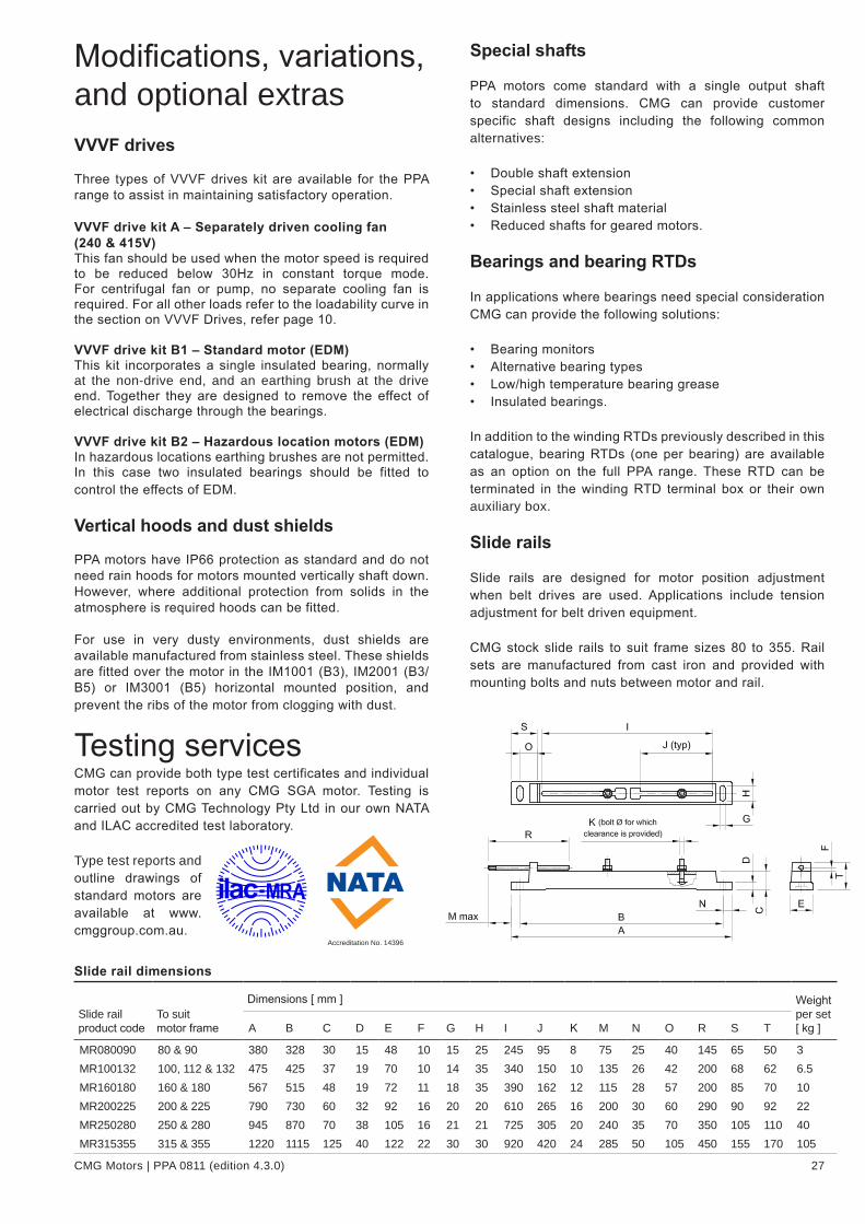
CMG Motors | PPA 0811 (edition 4.3.0) 27
Slide rail dimensions
Slide rail product code
To suit motor frame
Dimensions [ mm ] Weight per set [ kg ]A B C D E F G H I J K M N O R S T
MR080090 80 & 90 380 328 30 15 48 10 15 25 245 95 8 75 25 40 145 65 50 3MR100132 100, 112 & 132 475 425 37 19 70 10 14 35 340 150 10 135 26 42 200 68 62 6.5MR160180 160 & 180 567 515 48 19 72 11 18 35 390 162 12 115 28 57 200 85 70 10MR200225 200 & 225 790 730 60 32 92 16 20 20 610 265 16 200 30 60 290 90 92 22MR250280 250 & 280 945 870 70 38 105 16 21 21 725 305 20 240 35 70 350 105 110 40MR315355 315 & 355 1220 1115 125 40 122 22 30 30 920 420 24 285 50 105 450 155 170 105
Modifications, variations, and optional extrasVVVF drives
Three types of VVVF drives kit are available for the PPA range to assist in maintaining satisfactory operation.
VVVF drive kit A – Separately driven cooling fan (240 & 415V)This fan should be used when the motor speed is required to be reduced below 30Hz in constant torque mode. For centrifugal fan or pump, no separate cooling fan is required. For all other loads refer to the loadability curve in the section on VVVF Drives, refer page 10.
VVVF drive kit B1 – Standard motor (EDM)This kit incorporates a single insulated bearing, normally at the non-drive end, and an earthing brush at the drive end. Together they are designed to remove the effect of electrical discharge through the bearings.
VVVF drive kit B2 – Hazardous location motors (EDM)In hazardous locations earthing brushes are not permitted. In this case two insulated bearings should be fitted to control the effects of EDM.
Vertical hoods and dust shields
PPA motors have IP66 protection as standard and do not need rain hoods for motors mounted vertically shaft down. However, where additional protection from solids in the atmosphere is required hoods can be fitted.
For use in very dusty environments, dust shields are available manufactured from stainless steel. These shields are fitted over the motor in the IM1001 (B3), IM2001 (B3/B5) or IM3001 (B5) horizontal mounted position, and prevent the ribs of the motor from clogging with dust.
Testing services CMG can provide both type test certificates and individual motor test reports on any CMG SGA motor. Testing is carried out by CMG Technology Pty Ltd in our own NATA and ILAC accredited test laboratory.
Type test reports and outline drawings of standard motors are available at www.cmggroup.com.au.
Special shafts
PPA motors come standard with a single output shaft to standard dimensions. CMG can provide customer specific shaft designs including the following common alternatives:
• Double shaft extension• Special shaft extension• Stainless steel shaft material• Reduced shafts for geared motors.
Bearings and bearing RTDs
In applications where bearings need special consideration CMG can provide the following solutions:
• Bearing monitors• Alternative bearing types• Low/high temperature bearing grease• Insulated bearings.
In addition to the winding RTDs previously described in this catalogue, bearing RTDs (one per bearing) are available as an option on the full PPA range. These RTD can be terminated in the winding RTD terminal box or their own auxiliary box.
Slide rails
Slide rails are designed for motor position adjustment when belt drives are used. Applications include tension adjustment for belt driven equipment.
CMG stock slide rails to suit frame sizes 80 to 355. Rail sets are manufactured from cast iron and provided with mounting bolts and nuts between motor and rail.
Accreditation No. 14396

28 CMG Motors | PPA 0811 (edition 4.3.0)
Installation and maintenancePPA series motors are designed and manufactured to be robust and reliable for minimal maintenance. The following items should be taken into consideration to ensure trouble free installation and reliable running throughout the motors’ life.
Inspection
On receipt of the motor check the following:• Rating plate details and enclosure are as ordered• Shaft turns freely• Motor was not damaged during transport• Condensation drain holes are in the correct position
for the motor mounting application. (They should be located at the lowest point of the motor when it is in its operating position.)
• If the winding is meggered to earth, ensure that the thermal protectors are not inadvertently damaged. (The thermistor leads should be shorted together whilst meggering takes place).
Storage
When the motor is not for immediate use store in a clean, dry location, free from vibration. (Bearings are susceptible to damage from vibration.)
Ensure shaft locking clamps, where supplied, are fitted securely. Anti-condensation heaters, where fitted, should be energised if the environment is likely to be damp.
Installation
The following items should be considered when installing to ensure motor reliability:
SurroundingsEnsure that the motor is properly protected against ingress of oil, water or dust if construction work is in progress around the motor.
Shaft locking clampMotors 200 frame and above are fitted with a shaft-locking clamp. The clamp should remain fitted for as long as possible, preferably until the motor is put into service. Motors that are likely to remain stationary for lengthy periods should have locking clamps refitted. Shaft-locking clamps stop axial movement of the rotor assembly caused by vibration. This causes a phenomenon known as ‘false brinelling’, which eventually leads to premature bearing failure particularly where roller bearings are fitted.
Pulleys and couplings• Pulleys and couplings should be machined to H7 limits.
Both shaft and bore should be cleaned and lubricated. If the fit is still too tight the pulley or coupling should be heated up in air or oil to approximately 95°C.
• Shock methods must not be used in removing pulleys and couplings. Proper wheel or pulley removers should be used to prevent shaft and bearing damage.
Terminal box
PPA motors come standard with a terminal box on the right hand side viewed from drive end.
The following alternatives are available:
• Left hand terminal box – PPAL - 80-400 frame by modification of standard unit - 450 frame new manufacturing
• Removed terminal box – PPAF - fitted with a blanking plate and threaded conduit entry, and extended leads, including earth connector.
Special identification plates
Additional identification and warning plates in stainless steel or other specified materials can be fitted to this PPA range. These include:
• Equipment number plates• Direction of rotation (arrow) plates• RTD plates• Lubrication instruction plates.
Protection against harsh environments
Where environmental factors need special consideration CMG can provide the following modifications:
• Winding temperature monitors• Anti-condensation heaters on motors below frame 250• Separately driven cooling fans• Tropic proofing• Special paint finish.
Where the motor is to be installed in harsh chemical conditions optional surface treatments are available to protect against acid and alkaline splashing. In addition to these surface systems we are able to supply stainless steel nuts, bolts and screws, plus inlet fan grills manufactured from stainless steel.
Special fans
CMG offer a range of uni-directional and bi-directional low-noise fans.

CMG Motors | PPA 0811 (edition 4.3.0) 29
• Pulleys and couplings should be balanced before the keyway is cut to eliminate vibration caused by lack of balancing. (Rotor and shaft assemblies have been finely balanced during manufacture, and drive end shafts balanced with a half key.)
• When slide rails are used in conjunction with pulley drives the adjusting screw ends should be positioned between the motor and load at drive shaft end and the other diagonally opposite. This helps speedy and accurate belt aligning, tensioning and replacement.
Shafts and keysShafts are machined to AS1359.10-1985 dimensions.
Shaft diameter Tolerance Length Key size Seat
19 +0.009 -0.004 40 6x6x25 15.524 +0.009 -0.004 50 8x7x32 2028 +0.009 -0.004 60 8x7x40 2438 +0.018 +0.002 80 10x8x56 3342 +0.018 +0.002 110 12x8x80 3748 +0.018 +0.002 110 14x9x80 42.555 +0.030 +0.011 110 16x10x80 4960 +0.030 +0.011 140 18x11x110 5365 +0.030 +0.011 140 18x11x110 5870 +0.030 +0.011 140 20x12x110 62.575 +0.030 +0.011 140 20x12x110 67.580 +0.030 +0.011 170 22x14x140 7185 +0.035 +0.013 170 22x14x140 76100 +0.035 +0.013 210 28x16x160 90110 +0.035 +0.013 210 28x16x160 100125 +0.040 +0.015 210 32x18x160 114
Belt DrivesThe belt manufacturer’s recommendations for installation, alignment and tensioning must be strictly adhered to when fitting belt drives.
Direct couplingCare must be taken in checking alignment of driving and driven shafts. The motor and driven equipment must be in alignment from all aspects.
WARNING: MISALIGNMENT OF PULLEYS WILL LEAD TO PREMATURE BEARING FAILURE
ConnectionPPA motors should be connected to the rated voltage a follows:
up to 3kW Star (220-250V three phase Delta)4kW to 630kW Delta 710kW and above Delta (rated 690V)
PPA motors are suitable for use with both rated voltage DOL operation and rated voltage three phase variable frequency drives. 3kW and below can also be used with 220-250V three phase variable frequency drives.
Alternatively, 380-415kW, 4kW to 630kW Delta connected motors can be operated DOL, or in the Star configuration with a 690V supply or with a 690V variable frequency drive. When used with a VVVF drive they must be used in conjunction with an output reactor to protect the winding insulation. These motors are also suitable for Star/Delta starting.
For motors 710kW and above the standard connection is Delta with a minimum voltage of 690V.
Where special windings are supplied, a separate connection diagram will be supplied with the motor. All motors are provided with suitable earthing studs.
Running current check Check the running current of the motor on no load and full load.

30 CMG Motors | PPA 0811 (edition 4.3.0)
Basic maintenance
Bearings
When re-greasing motors ensure that the correct type of grease is used. If in doubt about the existing grease type, clean out old grease thoroughly from bearings and bearing housings, prior to regreasing.
WARNING: NEVER MIX GREASE TYPES
Grease replenishmentThe addition of fresh grease, to renew the original charge, must be made at regular intervals.
PPA motors with frames 80 to 100 are fitted with sealed bearing housing (non regreasable). Thru-flushing grease valves are fitted to all PPA motors. For frames 112 and above replenishment should be carried out whilst the motor is running. The rotating slinger expels excess grease through an exhaust port in the bearing cap ensuring the correct level of fresh grease is maintained in the bearing housing. See the table on page 31 for bearing relubrication volumes.
Grease packingAssemblyThe thru-flushing grease valve operates automatically and cannot be overgreased. This feature eliminates problems associated with overpacking as any excess will be expelled from the housing as the motor operates. (Overpacking can cause churning and over-heating which may result in breakdown of the grease and leakage from the housing. Too little grease can result in dry running and cage wear.)
BearingThe bearing itself should always be packed as full as possible, working the grease thoroughly into the bearing parts in order to ensure proper lubrication immediately upon starting.
Bearing capsThe most convenient way of packing bearing caps is to fill the inner-bearing cap completely and the outer bearing cap to one third of its capacity, preferably on the opposite side to the exhaust port.
DismantlingIf a motor is dismantled, cover the bearings with a plastic sheet or clean lint free rag to prevent ingress of foreign matter. Never use cotton waste.
Removing and fitting bearingsIf bearings are removed they should be renewed, not refitted. Proper drawing and fitting equipment must be used when removing bearings as the bearings have an interference fit on the shaft. Replacement bearings must be the correct size and have the correct internal clearance grade. See the table on page 31 for bearing sizes. C3 clearances are normally preferred.
Recommended grease typesGeneral purpose grease (standard)• Lithium hydroxy-stearate grease• NLGI consistency No. 3• Operating temperature -20°C to +120°C• High oxidation resistance• Retains consistency after extreme periods of service• Contains effective rust inhibitors• Shell Alvania no. 3 or equivalent.
Extreme temperature range grease (optional)• PTFE (Teflon) base with mineral oils• Operating temperature -40°C to +260°C• Non melting with high oxidation resistance• Retains consistency• Contains rust inhibitors• Magnalube G or equivalent.
Current
Check periodically that the current drawn is balanced and is the same as at the time of installation.
Cable terminations
Cable terminations should have all incoming supply leads compressed between two nuts, locked with a locking nut. Other combinations may cause overheating due to high resistance joints.
WARNING: THE CORRECT CLEARANCE BETWEEN LIVE PARTS MUST BE MAINTAINED
Thermal protection devices
StandardOne set (3) of PTC thermistors are embedded in the head windings. The leads are terminated in an auxiliary terminal box for PPA motors frame 160 and above, and terminate in the main terminal box for frames 80 to 132.
Resistance Temperature Detectors (RTDs) are fitted to windings of 315 frame and above (leads terminated in separate auxiliary terminal box).
OptionalOther thermal protection devices may be optionally fitted, including bearing RTDs, winding RTDs for smaller frames, additional sets of PTC thermistors, or bi-metal thermal protectors.
WARNING: DO NOT APPLY MORE THAN 2.5V ACROSS ANY PROTECTION DEVICE
Insulation testingWhen checking for insulation resistance (IR) the test voltage must not be applied across the protection device. The correct procedure is to short the entire protector leads together and apply the test voltage between the shorted leads and earth and/or phases. ‘Meggering’ across the terminals of the device, when not shorted, is likely to cause irreparable damage, and must not be carried out.

CMG Motors | PPA 0811 (edition 4.3.0) 31
PPA & PPC bearing size and relubrication dataStandard bearings Optional bearings
Drive end (ball bearing) Non-Drive end (ball bearing) Drive end (roller bearing)
Fame size
Bearing no.
Bearingsize
RelubricationBearingno.
Bearing size
RelubricationBearing no.
Bearing size
Relubrication
Qty [ g ]
Interval [ hours ]
Qty [ g ]
Interval [ hours ]
Qty [ g ]
Interval [ hours ]
3000 r/min = 2 pole112 6306 30x72x19 7 9000 6306 30x72x19 7 9000132 6308 40x90x23 11 7500 6308 40x90x23 11 7500160 6309 45x100x25 13 6500 6309 45x100x25 13 6500180 6310 50x110x27 15 6000 6310 50x110x27 15 6500200 6312 60x130x31 20 5000 6312 60x130x31 20 5000225 6313 65x140x33 23 4800 6313 65x140x33 23 4800250 6313 65x140x33 30 4200 6313 65x140x33 23 4800280 6314 70x150x35 37 2500 6314 70x150x35 26 4000315 6316 80x170x39 41 2000 6316 80x170x39 41 2000355 6318 90x190x43 41 2000 6318 90x190x43 41 2000400 6318 90x190x43 41 2000 6318 90x190x43 41 2000
1500 r/min = 4 pole112 6306 30x72x19 7 12000 6306 30x72x19 7 12000 NU306 30x72x19 7 11000132 6308 40x90x23 11 11000 6308 40x90x23 11 11000 NU308 40x90x23 11 9500160 6309 45x100x25 13 11000 6309 45x100x25 13 11000 NU309 45x100x25 13 8500180 6310 50x110x27 15 10500 6310 50x110x27 15 11000 NU310 50x110x27 15 8500200 6312 60x130x31 20 10000 6312 60x130x31 20 10000 NU312 60x130x31 20 6000225 6313 65x140x33 23 9500 6313 65x140x33 23 9500 NU313 65x140x33 23 7000250 6315 75x160x37 30 9100 6313 65x140x33 23 9500 NU315 75x160x37 30 7000280 6317 85x180x41 37 8900 6314 70x150x35 26 8900 NU317 85x180x41 37 6800315 NU318 90x190x43 41 6500 6316 80x170x39 41 7000355 NU324 120x260x55 72 4000 6324 120x260x55 72 7000400 NU326 130x280x58 81 3500 6326 130x280x58 81 6200450 NU328 140x210x62 93 2500 6326 130x280x58 81 6200
1000 r/min = 6 pole112 6306 30x72x19 7 17000 6306 30x72x19 7 17000 NU306 30x72x19 7 14000132 6308 40x90x23 11 15000 6308 40x90x23 11 15000 NU308 40x90x23 11 11000160 6309 45x100x25 13 14000 6309 45x100x25 13 14000 NU309 45x100x25 13 8500180 6310 50x110x27 15 14000 6310 50x110x27 15 14000 NU310 50x110x27 15 8500200 6312 60x130x31 20 14000 6312 60x130x31 20 14000 NU312 60x130x31 20 6000225 6313 65x140x33 23 13500 6313 65x140x33 23 13500 NU313 65x140x33 23 7000250 6315 75x160x37 30 13000 6313 65x140x33 23 13500 NU315 75x160x37 30 7000280 6317 85x180x41 37 12500 6314 70x150x35 26 12500 NU317 85x180x41 37 6800315 NU318 90x190x43 41 9500 6316 80x170x39 41 10000355 NU324 120x260x55 72 8000 6324 120x260x55 72 7000400 NU326 130x280x58 81 7000 6326 130x280x58 81 6200450 NU328 140x210x62 93 4500 6326 130x280x58 81 6200
750 r/min = 8 pole112 6306 30x72x19 7 20000 6306 30x72x19 7 20000 NU306 30x72x19 7 17000132 6308 40x90x23 11 17000 6308 40x90x23 11 17000 NU308 40x90x23 11 13000160 6309 45x100x25 13 16000 6309 45x100x25 13 16000 NU309 45x100x25 13 8500180 6310 50x110x27 15 15500 6310 50x110x27 15 16000 NU310 50x110x27 15 8500200 6312 60x130x31 20 15000 6312 60x130x31 20 15000 NU312 60x130x31 20 6000225 6313 65x140x33 23 15000 6313 65x140x33 23 15000 NU313 65x140x33 23 7000250 6315 75x160x37 30 14500 6313 65x140x33 23 15000 NU315 75x160x37 30 7000280 6317 85x180x41 37 14000 6314 70x150x35 26 14000 NU317 85x180x41 37 6800315 NU318 90x190x43 41 13000 6316 80x170x39 41 13000355 NU324 120x260x55 72 10000 6324 120x260x55 72 7000400 NU326 130x280x58 81 9000 6326 130x280x58 81 6200450 NU328 140x210x62 93 7500 6326 130x280x58 81 6200
Note: The bearings fitted to 80, 90 & 100 frames are greased for life. For these bearing sizes, refer to the table listed on page 7.

CMG Motors | PPA 0811 (edition 4.3.0)Revised 0910
19 Corporate Ave / PO Box 2340Rowville VIC 3178 [email protected]: +61 (0)3 9237 4000Fax: +61 (0)3 9237 4010
AUSTRALIASales : 1300 888 853Support : 1800 676 722www.cmggroup.com.au
CMG Pty LtdABN 99 005 118 114
VICTORIA19 Corporate AveRowville VIC 3178Tel: +61 (0)3 9237 4040 Fax: +61 (0)3 9237 4050
NEW SOUTH WALES8/26 Powers RoadSeven Hills NSW 2147Tel: +61 (0)2 9674 1555 Fax: +61 (0)2 9674 4652
NORTH NEW SOUTH WALES13B Old Punt RoadTomago NSW 2322Tel: +61 (0)2 4964 9144Fax: +61 (0)2 4964 8537
QUEENSLAND1/6-8 Radium StreetCrestmead QLD 4132Tel: +61 (0)7 3803 2033 Fax: +61 (0)7 3803 2683
NORTH QUEENSLANDCnr. John Vella Drive & Connors RdPaget, Mackay NQLD 4740Tel: +61 (0)7 4952 6244 Fax: +61 (0)7 4952 6277
NORTHERN TERRITORY24 Benison RoadWinnellie NT 0820Tel: +61 (0)8 8947 2633 Fax: +61 (0)8 8947 1499
WESTERN AUSTRALIA21 Colin Jamieson DriveWelshpool WA 6106Tel: +61 (0)8 6253 3700Fax: +61 (0)8 6253 3710
SOUTH AUSTRALIA2/24 Richard StreetHindmarsh SA 5007Tel: +61 (0)8 8340 8333 Fax: +61 (0)8 8340 8800
TASMANIA112 Tarleton StreetEast Devonport TAS 7310Tel: +61 (0)3 6427 9911 Fax: +61 (0)3 6427 9922
HEAD OFFICE
CMG PRODUCTS ARE SOLD AND RECOMMENDED BY :
All CMG products are regularly redesigned and improved and CMG reserves the right to change the design, technical specifi cation and dimensions without prior notice. E&OE.
ASIA PACIFICwww.cmggroup.com.sg
SINGAPORECMG Electric Motors (Asia Pacifi c) Pte LtdRegistration No. 200414611G69 Tech Park CrescentSingapore 638073Tel: +65 6863 3473 Fax: +65 6863 3476
MALAYSIACMG Electric Motors (Malaysia) Sdn. BhdRegistration No. 796093-K6536A Jalan Bukit Kemuning, Batu 6, Seksyen 3440470 Shah Alam, MalaysiaTel: +603 5124 9217 Fax: +603 5124 6195www.cmggroup.com.my
CHINAwww.cmggroup.com.cn
SHANGHAICMG Electric Motors Trading (Shanghai) Co LtdRegistration No. 040714
Room 504, Building 28 200 Shuang Liao Road Shanghai, ChinaTel: +86 (0)21 3377 6268
UNITED KINGDOMCMG Electric Motors (UK) LtdRegistration No. 0459 5019 Unit A Stafford Park 2, TelfordShropshire TF3 3AR UKTel: +44 (0)1952 299 606 Fax: +44 (0)1952 299 667
MIDDLE EASTwww.cmggroup.co.il
ISRAELCMG Electric Motors (Israel) LtdCompany No. 513713107 9 Bareket St, Zone 23North Industrial Park Caesarea 38900Tel: +972 (0)4 627 0777Fax: +972 (0)4 627 0779
NEW ZEALANDSales : 0800 676 722www.cmggroup.co.nz
CMG Electric Motors (NZ) LtdNZCN : 567 351
AUCKLAND315A Rosebank RoadRosebank, Avondale, AucklandTel: +64 (0)9 820 3550 Fax: +64 (0)9 820 8504
CHRISTCHURCHCnr Lunns & Annex RoadMiddleton, ChristchurchTel: +64 (0)3 348 3740 Fax: +64 (0)3 348 3760
ROTORUA51 Pururu Street , Rotorua Tel: +64 (0)7 347 8624Fax: +64 (0)7 347 8629
SOUTH AFRICAwww.cmggroup.co.za
CMG Electric Motors South Africa (Pty) LtdRegistration No. 2003/001379/07
JOHANNESBURG268B Fleming RoadMeadowdale, GermistonJohannesburg 1614Tel: +27 (0)11 453 1930Fax: +27 (0)11 453 9560
DURBANUnit 13 Heron Park80 Corobrik RoadRiverhorse Valley EstateDurban 4017Tel: +27 (0)31 569 5551Fax: +27 (0)31 569 5549
MIDDELBURGUnit 6, 2 Rand StreetIndustrial AreaMiddelburg 1050Tel: +27 (0)13 246 1902Fax: +27 (0)13 246 1205
CAPE TOWNUnit 3, 52 Junction StreetTygerberg Industrial ParkParow IndustriaCape Town 7499Tel: +27 (0)21 951 2901Fax: +27 (0)21 951 2910