· Edificio Expo, c/ Inca Garcilaso s/n, E-41092 Seville – Spain Telephone: direct line (+34-95)...
397
Edificio Expo, c/ Inca Garcilaso s/n, E-41092 Seville – Spain Telephone: direct line (+34-95) 4488284, switchboard 4488-318. Fax: 4488-426. Internet: http://eippcb.jrc.es; Email: [email protected] EUROPEAN COMMISSION DIRECTORATE-GENERAL JRC JOINT RESEARCH CENTRE Institute for Prospective Technological Studies (Seville) Technologies for Sustainable Development European IPPC Bureau Integrated Pollution Prevention and Control Draft Reference Document on Best Available Techniques in the Smitheries and Foundries Industry Draft January 2004
Transcript of · Edificio Expo, c/ Inca Garcilaso s/n, E-41092 Seville – Spain Telephone: direct line (+34-95)...

Edificio Expo, c/ Inca Garcilaso s/n, E-41092 Seville – SpainTelephone: direct line (+34-95) 4488284, switchboard 4488-318. Fax: 4488-426.Internet: http://eippcb.jrc.es; Email: [email protected]
EUROPEAN COMMISSIONDIRECTORATE-GENERAL JRCJOINT RESEARCH CENTREInstitute for Prospective Technological Studies (Seville)Technologies for Sustainable DevelopmentEuropean IPPC Bureau
Integrated Pollution Prevention and Control
Draft Reference Document onBest Available Techniques in the Smitheries and
Foundries Industry
Draft January 2004

This document is one of a series of foreseen documents as below (at the time of writing, not alldocuments have been drafted):
Full title BREF code
Reference Document on Best Available Techniques for Intensive Rearing of Poultry and Pigs ILF
Reference Document on the General Principles of Monitoring MON
Reference Document on Best Available Techniques for the Tanning of Hides and Skins TAN
Reference Document on Best Available Techniques in the Glass Manufacturing Industry GLS
Reference Document on Best Available Techniques in the Pulp and Paper Industry PP
Reference Document on Best Available Techniques on the Production of Iron and Steel I&S
Reference Document on Best Available Techniques in the Cement and Lime Manufacturing Industries CL
Reference Document on the Application of Best Available Techniques to Industrial Cooling Systems CV
Reference Document on Best Available Techniques in the Chlor – Alkali Manufacturing Industry CAK
Reference Document on Best Available Techniques in the Ferrous Metals Processing Industry FMP
Reference Document on Best Available Techniques in the Non Ferrous Metals Industries NFM
Reference Document on Best Available Techniques for the Textiles Industry TXT
Reference Document on Best Available Techniques for Mineral Oil and Gas Refineries REF
Reference Document on Best Available Techniques in the Large Volume Organic Chemical Industry LVOC
Reference Document on Best Available Techniques in the Waste Water and Waste GasTreatment/Management Systems in the Chemical Sector CWW
Reference Document on Best Available Techniques in the Food, Drink and Milk Industry FM
Reference Document on Best Available Techniques in the Smitheries and Foundries Industry SF
Reference Document on Best Available Techniques on Emissions from Storage ESB
Reference Document on Best Available Techniques on Economics and Cross-Media Effects ECM
Reference Document on Best Available Techniques for Large Combustion Plants LCP
Reference Document on Best Available Techniques in the Slaughterhouses and Animals By-productsIndustries
SA
Reference Document on Best Available Techniques for Management of Tailings and Waste-Rock inMining Activities MTWR
Reference Document on Best Available Techniques for the Surface Treatment of Metals STM
Reference Document on Best Available Techniques for the Waste Treatments Industries WT
Reference Document on Best Available Techniques for the Manufacture of Large Volume InorganicChemicals (Ammonia, Acids and Fertilisers) LVIC-AAF
Reference Document on Best Available Techniques for Waste Incineration WI
Reference Document on Best Available Techniques for Manufacture of Polymers POL
Reference Document on Energy Efficiency Techniques ENE
Reference Document on Best Available Techniques for the Manufacture of Organic Fine Chemicals OFC
Reference Document on Best Available Techniques for the Manufacture of Specialty InorganicChemicals SIC
Reference Document on Best Available Techniques for Surface Treatment Using Solvents STS
Reference Document on Best Available Techniques for the Manufacture of Large Volume InorganicChemicals (Solids and Others) LVIC-S
Reference Document on Best Available Techniques in Ceramic Manufacturing Industry CER

Executive Summary
KV/EIPPCB/SF_Final_Draft Version January 2004 i
EXECUTIVE SUMMARY
The Smitheries and Foundries BREF (Best Available Techniques reference document) reflectsan information exchange carried out under Article 16(2) of Council Directive 96/61/EC. Thisexecutive summary is intended to be read in conjunction with the BREF’s Preface, whichexplains the structure of the document, its objectives, usage and legal terms. The executivesummary describes the main findings, the principal BAT conclusions and the associatedemission/consumption levels. It can be read and understood as a stand-alone document but, as asummary, it does not present all the complexities of the full BREF text. It is therefore notintended as a substitute for the full BREF text in BAT decision making.
Scope of this BREF
This document reflects the exchange of information on the activities covered by Annex I,categories 2.3 (b), 2.4 and 2.5 (b) of the IPPC Directive, i.e.
“2.3. Installations for the processing of ferrous metals:(b) smitheries with hammers the energy of which exceeds 50 kilojoule per hammer, where
the calorific power used exceeds 20 MW2.4. Ferrous metal foundries with a production capacity exceeding 20 tonnes per day2.5. Installations(b) for the smelting, including the alloyage, of non-ferrous metals, including recovered
products, (refining, foundry casting, etc.) with a melting capacity exceeding 4 tonnesper day for lead and cadmium or 20 tonnes per day for all other metals.”
After comparing the above descriptions to the actual capacitites of existing installations inEurope, the TWG outlined a working scope, which covered the following:
- the casting of ferrous materials, e.g. lamellar cast iron, malleable and nodular iron, steel- the casting of non-ferrous materials, e.g. aluminium, magnesium, copper, zinc, lead and
their alloys.
Smitheries were excluded from this document’s scope since no European smitheries werereported which met the conditions stated in Annex I 2.3.(b). This document therefore onlydiscusses foundry processes. Cadmium, titanium and precious metals foundries, as well as bellcasting and art casting foundries were also excluded on capacity grounds. Continuous casting(into sheets and slabs) has already been covered in the BREF documents related to iron andsteel production and non-ferrous metal industries, and therefore, it is not dealt with in thisdocument. In covering non-ferrous metals in this document, the process is considered to startwith the melting of ingots and internal scrap or with liquid metal.
From a process point of view, the following foundry process steps are covered in this document:
- pattern making- raw materials storage and handling- melting and metal treatment- mould and core production, and moulding techniques- casting or pouring and cooling- shake-out- finishing- heat treatment.

Executive Summary
ii Version January 2004 KV/EIPPCB/SF_Final_Draft
The foundry industry
Foundries melt ferrous and non-ferrous metals and alloys and reshape them into products at ornear their finished shape through the pouring and solidification of the molten metal or alloy intoa mould. The foundry industry is a differentiated and diverse industry. It consists of a widerange of installations, from small to very large; each with a combination of technologies andunit operations selected to suit the input, size of series and types of product produced by thespecific installation. The organisation within the sector is based on the type of metal input, withthe main distinction being made between ferrous and non-ferrous foundries. Since castings ingeneral are semi-finished products, foundries are located close to their customers.
The European foundry industry is the third largest in the world for ferrous castings and secondlargest for non-ferrous. The annual production of castings in the enlarged European Unionamounts to 11.7 million tonnes of ferrous and 2.8 million tonnes of non-ferrous castings.Germany, France and Italy are the top three production countries in Europe, with a total annualproduction of over two million tonnes of castings each. In recent years, Spain has taken over thefourth position from Great Britain, with both having a production of over one million tonnes ofcastings. Together, the top five countries produce more than 80 % of the total Europeanproduction. Although the production volume has remained relatively stable over the past fewyears, there has been a decline in the total number of foundries (now totalling around 3000units), which is also reflected in the employment numbers (now totalling around 260000people). This can be explained by progressive upscaling and automation in the foundry units.However, the foundry industry is predominantly still an SME industry, with 80 % of companiesemploying less than 250 people.
The main markets served by the foundry industry are the automotive (50 % of market share),general engineering (30 %) and construction (10 %) sectors. A growing shift of the automotiveindustry towards lighter vehicles has been reflected in a growth in the market for aluminium andmagnesium castings. While iron castings mostly (i.e. >60 %) go to the automotive sector, steelcastings find their market in the construction, machinery and valve making industries.
The foundry process
A general flow chart of the foundry process is depicted in the figure below. The process can bedivided into the following major activities:- melting and metal treatment: the melting shop- preparation of moulds and cores: the moulding shop- casting of the molten metal into the mould, cooling for solidification and removing the
casting from the mould: the casting shop- finishing of the raw casting: the finishing shop.
Various process options can be taken, depending on the type of metal, size of series and type ofproduct. Generally, the main division within the sector is based on the type of metal (ferrous ornon-ferrous) and the type of moulding used (lost moulds or permanent moulds). While anycombination is possible, typically ferrous foundries largely use lost moulds (i.e. sand moulding)and non-ferrous foundries mainly use permanent moulds (i.e. die-casting). Within each of thesebasic process options a variety of techniques exist according to the type of furnace used, themoulding and core-making system (green sand or various chemical binders) applied, and thecasting system and finishing techniques applied. Each of those have their own technical,economic and environmental properties, advantages and disadvantages.
Chapters 2, 3 and 4 of this document follow a process-flow approach to describe the variousoperations, from pattern making to finishing and heat treatment. Applied techniques aredescribed, emission and consumption levels given and techniques to minimise theenvironmental impact are discussed. The structure of Chapter 5 is based on a distinctionbetween the type of metal and the type of moulding.

Executive Summary
KV/EIPPCB/SF_Final_Draft Version January 2004 iii
Melting- ferrous:• cupola• induction• electric arc• rotary- non-ferrous:• induction• shaft• crucible• reverberatory
Metal treatment
Permanent mould maintenance
Lost mould making- sand mould
- sand core
- inserts
- pattern• wood, plastic,
metal- lost model• resin, wax
Manual mouldingMoulding automate
Casting- gravitational pouring - high-pressure- tilt pouring - centrifugal- low-pressure - continuous
Cooling
Shake-out / Take-outSand preparation
Sand regenerationFinishing-removal of casting system-shot blasting-deburring-thermal treatment
Raw materials, chemicals, patterns, dies
Finished castingSandLegend:
The foundry process
Key environmental issues
The foundry industry is a major player in the recycling of metals. Steel, cast iron and aluminiumscrap is remelted into new products. Most possible negative environmental effects of foundriesare related to the presence of a thermal process and the use of mineral additives. Environmentaleffects therefore are mainly related to the exhaust and off-gases and to the re-use or disposal ofmineral residues.
Emissions to air are the key environmental concern. The foundry process generates (metal-laden) mineral dusts, acidifying compounds, products of incomplete combustion and volatileorganic carbons. Dust is a major issue, since it is generated in all process steps, in varying typesand compositions. Dust is emitted from metal melting, sand moulding, casting and finishing.Any dust generated may contain metal and metal oxides.

Executive Summary
iv Version January 2004 KV/EIPPCB/SF_Final_Draft
The use of cokes as fuels, or the heating of crucibles and furnaces with gas or oil-fired burnerscan cause emissions of combustion products, such as NOx and SO2. Additionally, the use ofcokes and the presence of impurities (e.g. oil, paint, …) in scrap can cause the production ofsome products of incomplete combustion or recombination (such as PCDD/F) and dust.In the making of moulds and cores, various additives are used to bind the sand. In binding thesand and pouring the metal, reaction and decomposition products are generated. These includeinorganic and organic (e.g. amines, VOCs) compounds. The generation of decompositionproducts (mainly VOCs) further continues during the casting cooling and de-mouldingoperations. These products can also cause an odour nuisance.
In the foundry process, emissions to air will typically not be limited to one (or several) fixedpoint(s). The process involves various emission sources (e.g. from hot castings, sand, hotmetal). A key issue in emission reduction is not only to treat the exhaust and off-gas flow, butalso to capture it.
Sand moulding involves the use of large sand volumes, with sand-to-liquid-metal weight ratiosgenerally ranging from 1:1 up to 20:1. The used sand can be regenerated, re-used or disposed of.Additional mineral residues such as slag and dross are generated in the melting stage whenremoving impurities from the melt. These can be either re-used or disposed of.
Since foundries deal with a thermal process, energy efficiency and management of the generatedheat are important environmental aspects. However, due to the high amount of transport andhandling of the heat carrier (i.e. the metal) and its slow cooling, the recovery of heat is notalways straightforward.
Foundries may have a high water consumption e.g. for cooling and quenching operations. Inmost foundries, water management involves an internal circulation of water, with a major partof the water evaporating. The water is generally used in the cooling systems of electric furnaces(induction or arc) or cupola furnaces. In general, the final volume of waste water is very small.Nevertheless, when wet dedusting techniques are used, the generated waste water requiresspecial attention. In (high) pressure die-casting, a waste water stream is formed, which needstreatment to remove organic (phenol, oil) compounds before its disposal.
Consumption and emission levels
A general overview of the inputs and outputs of the foundry process is given in the figurebelow. The ‘Casting’ step mentioned in the centre of the picture covers also all necessarymoulding operations. The major input streams are metal, energy, binders and water. The keyemissions are dust, amines and VOCs, and for specific furnace types also SO2, dioxins and NOx.
The melting stage uses 40 – 60 % of the energy input. For a certain metal type, the energy use isdependent on the type of furnace used. The melting energy input ranges from 500 to1200 kWh/t metal charge for ferrous metals and from 400 to 1200 kWh/t metal charge foraluminium.
The amounts and types of binders, chemicals and sand used are very dependent on the type ofcasting made, especially regarding its size and shape, as well as whether serial or batch wiseproduction is used.
Water consumption is largely dependent on the type of furnace used, the type of flue-gascleaning applied and the casting method applied.
Dust is generated in each of the process steps, albeit with different levels of mineral oxides,metals and metal oxides. Dust levels for metal melting range from below detection limit, forcertain non-ferrous metals, to above 10 kg/tonne, for the cupola melting of cast iron. The high

Executive Summary
KV/EIPPCB/SF_Final_Draft Version January 2004 v
amount of sand used in lost mould casting results in dust emissions during the various mouldingstages.
Amines are used as a catalyst in the most commonly used core-making system. This results inguided emissions from the core-shooting machines and diffuse emissions from core-handling.
Volatile organic compounds emissions (mainly solvents, BTEX and to a lesser extent phenol,formaldehyde, etc.) result from the use of e.g. resins, organic solvents, or organic-basedcoatings in moulding and core-making. Organic compounds are thermally decomposed duringmetal pouring and are emitted further during shake-out and cooling. Emission levels between0.1 – 1.5 kg/tonne of casting are presented in this document.
Foundry ProcessMelting - Casting - Finishing
Metalscrap/ingots
Castings
Energy- fuel- electricity- heat Water
- cooling- scrubbing
Sand and Chemicals- additives melting and metal treatment- binders/release agents- oils and lubricants
Noise
Water- organics- metal dust
Solid- dust- used sand- dross - slag
Energy- heat- steam- hot water
Air- combustion and reaction products- particulate matter- pyrolysis and evaporation products
Odour
Mass stream overview of the foundry process
Techniques to consider in the determination of BAT
The minimisation of emissions, efficient raw material and energy usage, optimum processchemical utilisation, the recovering and recycling of waste and the substitution of harmfulsubstances are all important principles of the IPPC Directive. For foundries the focal points areair emissions, the efficient use of raw materials and energy, and waste reduction, in conjunctionwith any recycling and re-use options.
The environmental issues as mentioned above are addressed by using a variety of process-integrated and end-of-pipe techniques. Over 100 techniques for pollution prevention and controlare presented in this document, ordered under the following 12 thematic headings, which arelargely based on the process flow:

Executive Summary
vi Version January 2004 KV/EIPPCB/SF_Final_Draft
1. Raw material storage and handling: Materials storage and handling techniques aim at theprevention of soil and water pollution and optimisation of the internal recycling of scrapmetal.
2. Metal melting and molten metal treatment: For each furnace type, different techniques maybe considered for optimisation of the furnace efficiency and minimisation of any residueproduction. These mainly involve in-process measures. Environmental considerations canalso be taken into account in the selection of the furnace type. Special attention is paid tocleaning of the aluminium melt and the melting of magnesium, due to the high pollutionpotential of the products used until recently (HCE and SF6).
3. Mould- and core-making, including sand preparation: Best practice measures andtechniques for minimising the consumption may be applied for each type of binder systemand for die-casting release agents. For the reduction of VOCs and odour emissions from lostmould systems, water-based coatings and inorganic solvents may be considered. Whilewater-based coatings are commonly used, the applicability of inorganic solvents in core-making is still limited. Another approach is the use of different moulding methods.However, those techniques are used only in specific fields of application.
4. Metal casting: In order to improve the efficiency of the casting process, measures aimed atincreasing the metal yield (i.e. the mass ratio of molten metal over finished casting) may beconsidered.
5. Fume, flue-gas and exhaust air capture and treatment: Dealing with the emissions to air inall the different foundry stages requires an adequate capture and treatment system to be inplace. According to the unit operation, various techniques may be considered, depending onthe type of compounds emitted, the off-gas volume and the ease of capture. Techniquesapplied for off-gas capture play an important role in the reduction of fugitive emissions.Additionally, for fugitive emissions, good practice measures may be considered.
6. Waste water prevention and treatment: In many cases, waste water can be prevented orminimised by taking in-process measures. Waste water that cannot be prevented, willcontain mineral or metal dust, amines, suphates, oil or lubricants, depending on its sourcewithin the process. The applicable treatment techniques differ for each of these compounds.
7. Energy efficiency: Metal melting consumes 40 – 60 % of the energy input of a foundry.Energy efficiency measures should therefore take both the melting and the other processes(e.g. air compression, plant actuation, hydraulics) into account. The need for furnace andoff-gas cooling generates a hot water or hot air stream, which may allow an internal orexternal utilisation of the heat.
8. Sand: regeneration, recycling, re-use and disposal: Since foundries make intensive use ofsand as an inert primary material, the regeneration or re-use of this sand is an importantpoint of consideration as part of its environmental performance. Various techniques areapplied for regeneration of the sand (i.e. treatment and internal re-use as moulding sand),the selection of which depends on the binder type and the sand flow compostion. If sand isnot regenerated, then external re-use may be considered in order to prevent the need for itsdisposal. Its application in various areas has been demonstrated.
9. Dust and solid residues: treatment and re-use: In-process techniques and operationalmeasures may be considered for the minimisation of dust and residues. The collected dusts,slags and other solid residues may find an internal or external re-use.
10. Noise reduction: Various foundry activities are point sources of noise. For foundries nearhousing, this may cause a nuisance to the neighbours. The setting up and implementation ofa noise reduction plan, covering both general and source-specific measures, may thereforebe considered.
11. Decommissioning: The IPPC Directive requests attention be paid to consideration of thepossible pollution upon decommissioning of the plant. Foundries present a specific risk forsoil pollution at this stage. There are a number of general measures, which apply morewidely than just to foundries, which may be considered to prevent pollution at thedecommissioning stage.
12. Environmental management tools: Environmental management systems are a useful tool toaid the prevention of pollution from industrial activities in general. Their presentation istherefore a standard part of each BREF document.

Executive Summary
KV/EIPPCB/SF_Final_Draft Version January 2004 vii
BAT for foundries
The BAT chapter (Chapter 5) identifies those techniques that the TWG considered to be BAT ina general sense for the foundry industry, based upon the information in Chapter 4 and takingaccount of the Article 2(11) definition of “best available techniques” and the considerationslisted in Annex IV to the Directive. The BAT chapter does not set or propose emission limitvalues but suggests emission levels that are associated with the use of BAT.
During the information exchange by the TWG, many issues were raised and discussed. Aselection of these are highlighted in this summary.The following paragraphs summarise the keyBAT conclusions relating to the most relevant environmental issues.
The BAT elements will need to be adapted to the foundry type. A foundry basically consists ofa melting shop and a casting shop, both with their own supply chain. For lost mould casting thissupply chain includes all activities related to moulding and core-making. In the BAT chapter, adistinction is made between the melting of either ferrous or non-ferrous metal, and for casting ineither lost or permanent moulds. Each foundry may be classified as a combination of aparticular melting with an associated moulding class. BAT is presented for each class. GenericBAT, which are common to all foundries, are also presented.
Generic BATSome BAT elements are generic and apply for all foundries, regardless of the processes theyutilise and the type of products they produce. These concern material flows, finishing ofcastings, noise, waste water, environmental management and decommissioning.
BAT is to optimise the management and control of internal flows, in order to prevent pollution,prevent deterioration, provide adequate input quality, allow recycling and re-use and to improvethe process efficiency. The BREF refers to storage and handling techniques covered in theStorage BREF, but also adds some foundry specific BAT related to storage and handling, suchas the storage of scrap on an impermeable surface with a drainage and collection system(although applying a roof can reduce the need for such a system), the separate storage ofincoming materials and residues, the use of recyclable containers, optimisation of the metalyield, and good practice measures for molten metal transfer and ladle handling.
BAT are given for finishing techniques that generate dust and for heat treatment techniques. Forabrasive cutting, shot blasting and fettling, BAT is to collect and treat the finishing off-gas usinga wet or dry system. For heat treatment, BAT is to use clean fuels (i.e. natural gas or low-levelsulphur content fuel), automated furnace operation and burner/heater control and also to captureand evacuate the exhaust gas from heat treatment furnaces.
Concerning noise reduction, BAT is to develop and implement a noise reduction strategy, withgeneral and source-specific measures, being applicable, such as using enclosure systems forhigh-noise unit operations such as shake-out and using additional measures depending on andaccording to local conditions.
BAT for waste water management includes prevention, separation of the waste water types,maximising internal recycling and applying an adequate treatment for each final flow. Thisincludes techniques utilising e.g. oil interceptors, filtration or sedimentation.
Fugitive emissions arise from uncontained sources (transfers, storage, spills) and the incompleteevacuation of contained sources. BAT is to apply a combination of measures concerningmaterial handling and transport and to optimise exhaust gas capture and cleaning through one ormore capture techniques. Preference is given to collection of the fume nearest to the source.
BAT is to implement and adhere to an Environmental Management System (EMS) thatincorporates, as appropriate to individual circumstances, features concerning e.g. the

Executive Summary
viii Version January 2004 KV/EIPPCB/SF_Final_Draft
commitment of top management, planning, establishing and implementing procedures,performance checking with corrective actions and reviews.
BAT is to apply all necessary measures to prevent pollution upon decommissioning. Theseinclude minimisation of the risks during the design stage, implementation of an improvementprogramme for existing installations and development and utilisation of a site closure plan fornew and existing installations. In these measures, at least the following process parts areconsidered: tanks, vessels, pipework, insulation, lagoons and landfills.
Ferrous metal meltingFor the operation of cupola furnaces, BAT includes techniques which can give increasedefficiency, such as divided blast operation, oxygen enrichment, continuous blowing or longcampaign operation, good melting practice measures, and control of the coke quality. BAT is tocollect, cool and dedust the off-gas, and to apply post combustion and heat recovery underspecific conditions. Several dedusting systems are BAT but wet dedusting is preferable whenmelting with basic slag and in some cases as one of the measures to prevent and minimisedioxin and furan emissions. Industry has expressed doubts on the implementation of secondarymeasures for dioxin and furan abatement that have only been proven in other sectors and inparticular questions their applicability for smaller foundries. For cupolas, BAT for residuemanagement includes minimising slag forming, pretreating the slags in order to allow theirexternal re-use and collecting and recycling coke breeze.
For the operation of electric arc furnaces, BAT includes applying reliable and efficient processcontrols to shorten the melting and treatment time, using the foamy slag practice, efficientlycapturing the furnace off-gas, cooling the furnace off-gas and dedusting using a bag filter. BATis to recycle the filter dust into the EAF furnace.
For the operation of induction furnaces, BAT is to melt clean scrap; use good practice measuresfor the charging and operation; use medium frequency power and, when installing a newfurnace, to change any mains frequency furnace to medium frequency; to evaluate thepossibility of waste heat recuperation and under specific conditions to implement a heatrecovery system. For exhaust capture and treatment from induction furnaces, BAT is to use ahood, lip extraction or cover extraction on each induction furnace to capture the furnace off-gasand maximise the off-gas collection during the full working cycle; to use dry flue-gas cleaning;and to keep dust emissions below 0.2 kg/tonne molten iron.
For the operation of rotary furnaces, BAT is to implement a combination of measures tooptimise furnace yield and to use an oxyburner. BAT is to collect the off-gas close to thefurnace exit, apply post combustion, cool it using a heat-exchanger and then to apply drydedusting. For the prevention and minimisation of dioxin and furan emissions, BAT is to use acombination of specified measures. Similarly to the situation with cupola furnaces, industry hasexpressed doubts on the implementation of secondary measures for dioxin and for an abatementthat have only been proven in other sectors and in particular questions their applicability forsmaller foundries.
The actual metal treatment applied depends on the type of product made. BAT is to collect theexhaust gas from AOD converters using a roof canopy and to collect and treat the off-gas fromnodularisation, using a bag filter. BAT is also to make the MgO-dust available for recycling.
Non-ferrous metal meltingFor the operation of induction furnaces for melting aluminium, copper, lead and zinc, BAT is touse good practice measures for the charging and operation; to use medium frequency powerand, when installing a new furnace, change any mains frequency furnace to medium frequency;to evaluate the possibility of waste heat recuperation and under specific conditions to implementa heat recovery system. For exhaust capture from these furnaces, BAT is to minimise emissionsand if needed to collect the off-gas, maximising the off-gas collection during the full workingcycle and applying dry flue-gas cleaning.

Executive Summary
KV/EIPPCB/SF_Final_Draft Version January 2004 ix
For the other furnace types, BAT mainly focuses on the efficient collection of furnace off-gasand/or the reduction of fugitive emissions.
For non-ferrous metal treatment, BAT is to use an impeller station for the degassing andcleaning of aluminium. BAT is to use SO2 as a covering gas for magnesium melting ininstallations with an annual output of 500 tonnes and more. For small plants (<500 tonnes Mgparts output/year) BAT is to use SO2 or to minimise the use of SF6. In the case where SF6 isused, the BAT associated consumption level is <0.9 kg/tonne casting for sand casting and <1.5kg/tonne casting for pressure die-casting.
Lost mould castingLost mould casting involves moulding, core-making, pouring, cooling and shake-out. Thisincludes the production of green sand or chemically-bonded sand moulds and chemically-bonded sand cores. BAT elements are presented in three categories: green sand moulding,chemical sand moulding and pouring/cooling/shake-out.
For green sand preparation, BAT items deal with exhaust capture and cleaning and the internalor external recycling of the captured dust. In line with the goal of minimising waste for disposal,BAT is to apply a primary regeneration of green sand. Regeneration ratios of 98 % (monosand)or 90 – 94 % (green sand with incompatible cores) are associated with the use of BAT.
For chemically-bonded sand, the proposed BAT cover a variety of techniques, and deal with abroad range of environmental issues. BAT is to minimise the binder and resin consumption andsand losses, to minimise fugitive VOC emissions by capturing the exhaust gas from core-making and core handling, and to use water-based coatings. The use of alcohol-based coatingsis BAT in a limited number of applications, where water-based coatings cannot be applied. Inthis case, the exhaust should be captured at the coating stand, whenever this is feasible. Aspecific BAT is given for amine-hardened urethane-bonded (i.e. cold-box) core preparation, tominimise amine emissions and optimise amine recovery. For these systems both aromatic andnon-aromatic solvents are BAT. BAT is to minimise the amount of sand going to disposal,primarily by adopting a strategy of regeneration and/or re-use of chemically-bonded sand (asmixed or monosand). In the case of regeneration, the BAT conditions are given in the tablebelow. Regenerated sand is re-used only in compatible sand systems.
Sand type Technique Regeneration ratio1
(%)Cold setting monosand Simple mechanical regeneration 75 – 80Silicate monosand Heating and pneumatic treatment 45 – 85Monosands of cold-box, SO2,hot-box, croningMixed organic sands
Cold mechanical or thermal regeneration in cores: 40 – 100in moulds: 90 – 100
Mixed green and organic sand Mechanical-thermal-mechanicaltreatment, grinding or pneumatic chafing
in cores: 40 – 100in moulds: 90 – 100
(1) mass of regenerated sand/total mass of sand used
BAT for chemically-bonded sand regeneration (mixed and monosand)
Alternative moulding methods and inorganic binders are considered to have a promisingpotential for minimisation of the environmental impacts of moulding and casting processes.
Pouring, cooling and shake-out generate emissions of dust, VOCs and other organic products.BAT is to enclose pouring and cooling lines and provide exhaust extraction, for serial pouringlines, and to enclose the shake-out equipment, and treat the exhaust gas using wet or drydedusting.

Executive Summary
x Version January 2004 KV/EIPPCB/SF_Final_Draft
Permanent mould castingDue to the different nature of the process, the environmental issues for permanent mould castingrequire a different focus than those for lost mould techniques, with water as a more prominentitem. Emissions to air are in the form of an oil mist, rather than the dust and combustionproducts encountered in the other processes. BAT therefore focusses on prevention measuresinvolving minimisation of the water and release agent consumption. BAT is to collect and treatrun-off water and leakage water, using oil interceptors and distillation, vacuum evaporation orbiological degradation. If oil mist prevention measures do not allow a foundry to reach the BATassociated emission level, BAT is to use hooding and electrostatic precipitation for the exhaustof HPDC machines.
BAT for chemically-bonded sand preparation is analogous to the elements mentioned for lostmould casting. BAT for used sand management is to enclose the de-coring unit and to treat theexhaust gas using wet or dry dedusting. If a local market exists, BAT is to make the sand fromde-coring available for recycling.
BAT associated emission levelsThe following emission levels are associated to the BAT measures stated above.
Activity Type Parameter Emission level(mg/Nm³)
Finishing of castings Dust 5 – 20Ferrous metal melting General Dust (1) 5 – 20
PCDD/PCDF � 0.1 ng TEQ/Nm3
Hot Blast Cupola CO 20 – 1000SO2 20 – 100NOx 10 – 200
Cold Blast Cupola SO2 100 – 400NOx 20 – 70NM - VOC 10 – 20
Cokeless Cupola NOx 160 – 400Electric Arc Furnace NOx 10 – 50
CO 200Rotary Furnace SO2 70 – 130
NOx 50 – 250CO 20 – 30
Non-ferrous metal melting General Dust 1 – 20Aluminium melting Chlorine 3Shaft furnace for Al SO2 30 – 50
NOx 120CO 150VOC 100 – 150
Hearth type furnace for Al SO2 15NOx 50CO 5TOC 5
Moulding and casting usinglost moulds
General Dust 5 – 20
Core shop Amine 5Regeneration units SO2 120
NOx 150Permanent mould casting General Dust 5 - 20
Oil mist,measured astotal C
5 - 10
(1) the emission level of dust depends on the dust components, such as heavy metals, dioxins, and its massflow.
Emissions to air associated with the use of BAT for the various foundry activities
Executive Summary
KV/EIPPCB/SF_Final_Draft Version January 2004 xi
All associated emission levels are quoted as an average over the practicable measuring period.Whenever continuous monitoring is practicable, a daily average value is used. Emissions to airare based on standard conditions, i.e. 273 K, 101.3 kPa and dry gas.
While the BAT reference documents do not set legally binding standards, they are meant to giveinformation for the guidance of industry, Member States and the public on achievable emissionand consumption levels when using specified techniques. The appropriate limit values for anyspecific case will need to be determined taking into account the objectives of the IPPC Directiveand the local considerations.
Emerging techniques
Some new techniques for minimisation of the environmental impacts are currently still in theresearch and development phase or are only just beginning to enter the market these areconsidered to be emerging techniques. Five of these techniques are discussed in Chapter 6,namely: the use of low combustible materials in cupola melting, the recycling of metal-bearingfilter dust, amine recovery by waste-gas permeation, the separate spraying of release agent andwater in aluminium die-casting, and inorganic binder material for core-making. The lattertechnique was especially pointed out by the TWG as promising, although the current limitedscale of testing and implementation does not allow it to be yet incorporated as a technique toconsider in the selection of BAT.
Concluding remarks on the exchange of information
Information exchangeThe BREF document is based on more than 250 sources of information. Foundry researchinstitutes provided an important share of this information and played an active role in theinformation exchange. Local BAT notes from various Member States gave the informationexchange a firm basis. The majority of the documents provided in the information exchangedealt with processes and techniques as applied in ferrous foundries. Throughout the writing ofthe BREF the non-ferrous foundry processes have been underrepresented. This is reflected in alower level of detail in the BAT conclusions for non-ferrous foundries.
Level of consensusA good general level of consensus was reached on the conclusions and no split views wererecorded. The industry representation added a comment, expressing their doubt on the ease ofimplementation of secondary measures for dioxin abatement.
Recommendations for future workThe information exchange and the result of this exchange, i.e. this document, present animportant step forward in achieving the integrated prevention and control of pollution from thefoundry industry. Future work could continue this purpose by focusing on the collection andassessment of information that was not provided during this information exchange. In particular,in future work should cover in more detail the following topics:
- Techniques for VOC abatement: There is a need for data and information on methodsapplied for the efficient capture and treatment of VOC-laden exhaust gases from foundries.The use of alternative binder and coating materials may prove to be an important preventionmeasure in this respect
- Waste water treatment: There is a need for data from a broad range of water treatmentsystems in foundries, this should also show emission levels in relation to the inputs andtreatment techniques applied

Executive Summary
xii Version January 2004 KV/EIPPCB/SF_Final_Draft
- Melting of non-ferrous metals: Emission data for non-ferrous foundries are presented in thisdocument only for some specific installations. There is a need for more completeinformation on both guided and fugitive emissions from non-ferrous metal melting infoundries. This should be based on operational practice and expressed both as emissionlevels and mass flows..
- Economic data for BAT techniques: There is a lack of economic information for many of thetechniques presented in Chapter 4. This information needs to be collected from projectsdealing with the implementation of the presented techniques.
Suggested topics for R&D projectsThe information exchange has also exposed some areas where additional useful knowledgecould be gained from research and development projects. These relate to the following subjects:
- Dioxin monitoring and abatement: There is a need for a better understanding of theinfluence of process parameters on the formation of dioxins. This requires the monitoring ofdioxin emissions for various installations and under varying conditions. Additionally, thereis a need for research on the use and effectiveness of secondary measures for dioxinabatement in the foundry industry
- Mercury emissions: The high volatility of mercury may cause gaseous emissions, which arenot related to dust. In view of the implementation of a European policy on mercuryemissions, there is a need for research into the emissions of mercury from melting processesin general and from (non-ferrous) foundries in particular
- Oxygas burners and their use in cupola furnaces: The TWG reported that new applicationshave been set-up as a result of ongoing research. There is scope for further research anddevelopment here, to bring this technique up to a development level that allows its furtherdissemination.

Preface
KV/EIPPCB/SF_Final_Draft Version January 2004 xiii
PREFACE
1. Status of this document
Unless otherwise stated, references to “the Directive” in this document mean the CouncilDirective 96/61/EC on integrated pollution prevention and control. As the Directive applieswithout prejudice to Community provisions on health and safety at the workplace, so does thisdocument.
This document is a working draft of the European IPPC Bureau. It is not an official publicationof the European Communities and does not necessarily reflect the position of the EuropeanCommission.
2. Relevant legal obligations of the IPPC Directive and the definition of BAT
In order to help the reader understand the legal context in which this document has been drafted,some of the most relevant provisions of the IPPC Directive, including the definition of the term“best available techniques”, are described in this preface. This description is inevitablyincomplete and is given for information only. It has no legal value and does not in any way alteror prejudice the actual provisions of the Directive.
The purpose of the Directive is to achieve integrated prevention and control of pollution arisingfrom the activities listed in its Annex I, leading to a high level of protection of the environmentas a whole. The legal basis of the Directive relates to environmental protection. Itsimplementation should also take account of other Community objectives such as thecompetitiveness of the Community’s industry thereby contributing to sustainable development.
More specifically, it provides for a permitting system for certain categories of industrialinstallations requiring both operators and regulators to take an integrated, overall look at thepolluting and consuming potential of the installation. The overall aim of such an integratedapproach must be to improve the management and control of industrial processes so as to ensurea high level of protection for the environment as a whole. Central to this approach is the generalprinciple given in Article 3 that operators should take all appropriate preventative measuresagainst pollution, in particular through the application of best available techniques enablingthem to improve their environmental performance.
The term “best available techniques” is defined in Article 2(11) of the Directive as “the mosteffective and advanced stage in the development of activities and their methods of operationwhich indicate the practical suitability of particular techniques for providing in principle thebasis for emission limit values designed to prevent and, where that is not practicable, generallyto reduce emissions and the impact on the environment as a whole.” Article 2(11) goes on toclarify further this definition as follows:
“techniques” includes both the technology used and the way in which the installation isdesigned, built, maintained, operated and decommissioned;
“available” techniques are those developed on a scale which allows implementation in therelevant industrial sector, under economically and technically viable conditions, taking intoconsideration the costs and advantages, whether or not the techniques are used or producedinside the Member State in question, as long as they are reasonably accessible to the operator;
“best” means most effective in achieving a high general level of protection of the environmentas a whole.
Furthermore, Annex IV of the Directive contains a list of “considerations to be taken intoaccount generally or in specific cases when determining best available techniques … bearing inmind the likely costs and benefits of a measure and the principles of precaution and prevention”.

Preface
xiv Version January 2004 KV/EIPPCB/SF_Final_Draft
These considerations include the information published by the Commission pursuant toArticle 16(2).
Competent authorities responsible for issuing permits are required to take account of the generalprinciples set out in Article 3 when determining the conditions of the permit. These conditionsmust include emission limit values, supplemented or replaced where appropriate by equivalentparameters or technical measures. According to Article 9(4) of the Directive, these emissionlimit values, equivalent parameters and technical measures must, without prejudice tocompliance with environmental quality standards, be based on the best available techniques,without prescribing the use of any technique or specific technology, but taking into account thetechnical characteristics of the installation concerned, its geographical location and the localenvironmental conditions. In all circumstances, the conditions of the permit must includeprovisions on the minimisation of long-distance or transboundary pollution and must ensure ahigh level of protection for the environment as a whole.
Member States have the obligation, according to Article 11 of the Directive, to ensure thatcompetent authorities follow or are informed of developments in best available techniques.
3. Objective of this Document
Article 16(2) of the Directive requires the Commission to organise “an exchange of informationbetween Member States and the industries concerned on best available techniques, associatedmonitoring and developments in them”, and to publish the results of the exchange.
The purpose of the information exchange is given in recital 25 of the Directive, which states that“the development and exchange of information at Community level about best availabletechniques will help to redress the technological imbalances in the Community, will promotethe worldwide dissemination of limit values and techniques used in the Community and willhelp the Member States in the efficient implementation of this Directive.”
The Commission (Environment DG) established an information exchange forum (IEF) to assistthe work under Article 16(2) and a number of technical working groups have been establishedunder the umbrella of the IEF. Both IEF and the technical working groups includerepresentation from Member States and industry as required in Article 16(2).
The aim of this series of documents is to reflect accurately the exchange of information whichhas taken place as required by Article 16(2) and to provide reference information for thepermitting authority to take into account when determining permit conditions. By providingrelevant information concerning best available techniques, these documents should act asvaluable tools to drive environmental performance.
4. Information Sources
This document represents a summary of information collected from a number of sources,including in particular the expertise of the groups established to assist the Commission in itswork, and verified by the Commission services. All contributions are gratefully acknowledged.
5. How to understand and use this document
The information provided in this document is intended to be used as an input to thedetermination of BAT in specific cases. When determining BAT and setting BAT-based permitconditions, account should always be taken of the overall goal to achieve a high level ofprotection for the environment as a whole.
The rest of this section describes the type of information that is provided in each chapter of thedocument.

Preface
KV/EIPPCB/SF_Final_Draft Version January 2004 xv
Chapters 1 and 2 provide general information on the industrial sector concerned and on theindustrial processes used within the sector.
Chapter 3 provides data and information concerning current emission and consumption levels,reflecting the situation in existing installations at the time of writing.
Chapter 4 describes in more detail the emission reduction and other techniques that areconsidered to be most relevant for determining BAT and BAT-based permit conditions. Thisinformation includes the consumption and emission levels considered achievable by using thetechnique, some idea of the costs and the cross-media issues associated with the technique, andthe extent to which the technique is applicable to the range of installations requiring IPPCpermits, for example new, existing, large or small installations. Techniques that are generallyseen as obsolete are not included.
Chapter 5 presents the techniques and the emission and consumption levels that are consideredto be compatible with BAT in a general sense. The purpose is thus to provide generalindications regarding the emission and consumption levels that can be considered as anappropriate reference point to assist in the determination of BAT-based permit conditions or forthe establishment of general binding rules under Article 9(8). It should be stressed, however,that this document does not propose emission limit values. The determination of appropriatepermit conditions will involve taking account of local, site-specific factors such as the technicalcharacteristics of the installation concerned, its geographical location and the localenvironmental conditions. For existing installations, the economic and technical viability ofupgrading them also needs to be taken into account. Even the single objective of ensuring a highlevel of protection for the environment as a whole will often involve making trade-offjudgements between different types of environmental impact, and these judgements will oftenbe influenced by local considerations.
Although an attempt is made to address some of these issues, it is not possible for them to beconsidered fully in this document. The techniques and levels presented in Chapter 5 willtherefore not necessarily be appropriate for all installations. On the other hand, the obligation toensure a high level of environmental protection, including the minimisation of long-distance ortransboundary pollution, implies that permit conditions cannot be set on the basis of purely localconsiderations. It is therefore of the utmost importance that the information contained in thisdocument is fully taken into account by permitting authorities.
Since the best available techniques change over time, this document will be reviewed andupdated as appropriate. All comments and suggestions should be made to the European IPPCBureau at the Institute for Prospective Technological Studies at the following address:
Edificio Expo, c/ Inca Garcilaso, s/n, E-41092 Seville, SpainTelephone: +34 95 4488 284Fax: +34 95 4488 426e-mail: [email protected]: http://eippcb.jrc.es


KV/EIPPCB/SF_Final_Draft Version January 2004 xvii
Best Available Techniques Reference Document onSmitheries and Foundries
EXECUTIVE SUMMARY ........................................................................................................................ I
PREFACE ............................................................................................................................................. XIII
SCOPE.................................................................................................................................................XXXI
1 GENERAL INFORMATION ON FOUNDRIES ............................................................................11.1 Sector overview..........................................................................................................................1
1.1.1 Foundry industry .................................................................................................................11.1.2 Foundry markets..................................................................................................................81.1.3 Foundry types....................................................................................................................10
1.2 Environmental issues................................................................................................................111.2.1 Air .....................................................................................................................................111.2.2 Residues ............................................................................................................................111.2.3 Energy ...............................................................................................................................111.2.4 Water.................................................................................................................................11
2 APPLIED PROCESSES AND TECHNIQUES IN FOUNDRIES ...............................................132.1 Overview ..................................................................................................................................13
2.1.1 The foundry process ..........................................................................................................132.1.2 Iron casting........................................................................................................................152.1.3 Steel casting ......................................................................................................................172.1.4 Aluminium casting ............................................................................................................192.1.5 Magnesium casting............................................................................................................192.1.6 Copper casting...................................................................................................................202.1.7 Zinc casting .......................................................................................................................212.1.8 Lead casting ......................................................................................................................212.1.9 Casting of superalloys .......................................................................................................21
2.2 Pattern making..........................................................................................................................222.2.1 General pattern making .....................................................................................................222.2.2 Rapid prototyping (RP) .....................................................................................................23
2.3 Raw materials and raw material handling.................................................................................252.4 Melting and metal treatment.....................................................................................................28
2.4.1 Cupola furnaces.................................................................................................................292.4.1.1 Cold blast cupola furnace ............................................................................................29
2.4.1.1.1 Description ..........................................................................................................292.4.1.1.2 Maintenance ........................................................................................................302.4.1.1.3 Advantages:.........................................................................................................302.4.1.1.4 Disadvantages: ....................................................................................................30
2.4.1.2 Hot blast cupola furnace ..............................................................................................302.4.1.2.1 Description ..........................................................................................................302.4.1.2.2 Advantages:.........................................................................................................322.4.1.2.3 Disadvantages: ....................................................................................................32
2.4.1.3 Long campaign cupola.................................................................................................322.4.1.4 Nature of atmospheric emissions.................................................................................33
2.4.2 Electric arc furnace (EAF) ................................................................................................342.4.2.1 Description ..................................................................................................................342.4.2.2 Melting and refining with the acidic lined EAF ..........................................................352.4.2.3 Melting and refining with the basic lined EAF............................................................352.4.2.4 Nature of atmospheric emissions.................................................................................35
2.4.3 Induction furnace (IF) .......................................................................................................362.4.3.1 Coreless induction furnace ..........................................................................................36
2.4.3.1.1 Description ..........................................................................................................362.4.3.1.2 Melting practice ..................................................................................................382.4.3.1.3 Advantages:.........................................................................................................392.4.3.1.4 Disadvantages: ....................................................................................................39
2.4.3.2 Channel induction furnace...........................................................................................402.4.3.2.1 Description ..........................................................................................................402.4.3.2.2 Advantages:.........................................................................................................41

xviii Version January 2004 KV/EIPPCB/SF_Final_Draft
2.4.3.2.3 Disadvantages:.................................................................................................... 412.4.3.3 Nature of emissions..................................................................................................... 41
2.4.4 Radiant-roof furnace (resistance heated) .......................................................................... 422.4.5 Rotary furnace .................................................................................................................. 43
2.4.5.1 Description .................................................................................................................. 432.4.5.2 Melting practice .......................................................................................................... 432.4.5.3 Metallurgy................................................................................................................... 432.4.5.4 Application.................................................................................................................. 442.4.5.5 Advantages:................................................................................................................. 442.4.5.6 Disadvantages: ............................................................................................................ 44
2.4.6 Hearth type furnace........................................................................................................... 442.4.7 Shaft furnace..................................................................................................................... 45
2.4.7.1 Description .................................................................................................................. 452.4.7.2 Advantages:................................................................................................................. 462.4.7.3 Disadvantages: ............................................................................................................ 46
2.4.8 Crucible furnace................................................................................................................ 462.4.8.1 Description .................................................................................................................. 462.4.8.2 Melting practice .......................................................................................................... 472.4.8.3 Advantages:................................................................................................................. 472.4.8.4 Disadvantages: ............................................................................................................ 47
2.4.9 Argon Oxygen Decarburisation (AOD) converter for steel refining ................................ 482.4.10 Vacuum Oxygen Decarburisation converter (VODC) for steel refining........................... 482.4.11 Metal treatment of steel .................................................................................................... 492.4.12 Cast iron treatment............................................................................................................ 50
2.4.12.1 Alloying ...................................................................................................................... 502.4.12.2 Homogenisation .......................................................................................................... 502.4.12.3 Desulphurisation and recarburisation of cupola melted iron....................................... 502.4.12.4 Nodularisation treatment of the melt........................................................................... 512.4.12.5 Inoculation of the melt ................................................................................................ 52
2.4.13 Non-ferrous metal treatment ............................................................................................. 522.5 Mould and core production ...................................................................................................... 53
2.5.1 Raw materials ................................................................................................................... 542.5.1.1 Refractory materials .................................................................................................... 54
2.5.1.1.1 Silica sand........................................................................................................... 552.5.1.1.2 Chromite sand..................................................................................................... 562.5.1.1.3 Zircon sand ......................................................................................................... 562.5.1.1.4 Olivine sand........................................................................................................ 56
2.5.1.2 Binders and other chemicals ....................................................................................... 572.5.1.2.1 Bentonite............................................................................................................. 572.5.1.2.2 Resins.................................................................................................................. 572.5.1.2.3 Coal dust ............................................................................................................. 582.5.1.2.4 Cereal binders ..................................................................................................... 592.5.1.2.5 Iron oxide............................................................................................................ 59
2.5.1.3 Running, gating, feeding and filtration ....................................................................... 592.5.2 Sand preparation (transport, sieving, cooling, mixing)..................................................... 60
2.5.2.1 Sand conditioning for green sand moulding................................................................ 602.5.3 Moulding with natural sand .............................................................................................. 622.5.4 Moulding with clay-bonded sand (green sand moulding)................................................. 622.5.5 Moulding with unbonded sand (V-process)...................................................................... 632.5.6 Moulding and core-making with chemically-bonded sand ............................................... 65
2.5.6.1 Cold-setting processes................................................................................................. 652.5.6.1.1 Phenolic, acid catalysed...................................................................................... 652.5.6.1.2 Furan, acid catalysed .......................................................................................... 652.5.6.1.3 Polyurethane (phenolic isocyanate) .................................................................... 662.5.6.1.4 Resol – ester (alkaline phenolic ester hardened)................................................. 672.5.6.1.5 Alkyd oil, unbaked.............................................................................................. 672.5.6.1.6 Ester silicate........................................................................................................ 672.5.6.1.7 Cement................................................................................................................ 67
2.5.6.2 Gas-hardened processes .............................................................................................. 672.5.6.2.1 Cold-box (amine hardened phenolic urethane) ................................................... 682.5.6.2.2 Resol – ester (alkaline phenolics methyl formate hardened) .............................. 682.5.6.2.3 SO2 hardened furan resins................................................................................... 692.5.6.2.4 SO2 hardened epoxy/acrylic (free radical curing)............................................... 69

KV/EIPPCB/SF_Final_Draft Version January 2004 xix
2.5.6.2.5 CO2 hardened sodium silicate (water glass) ........................................................692.5.6.2.6 CO2 hardened alkaline phenolic ..........................................................................70
2.5.6.3 Hot curing processes....................................................................................................702.5.6.3.1 Hot-box, phenolic and/or furan based .................................................................702.5.6.3.2 Warm-box ...........................................................................................................712.5.6.3.3 Shell (Croning)....................................................................................................712.5.6.3.4 Linseed oil...........................................................................................................722.5.6.3.5 Alkyd oil, baked ..................................................................................................72
2.5.6.4 Coating of chemically-bonded sand moulds and cores................................................732.5.6.4.1 Composition of coatings......................................................................................732.5.6.4.2 Coating process ...................................................................................................73
2.5.7 Expendable pattern casting................................................................................................742.5.7.1 Unbonded sand – Lost Foam process ..........................................................................742.5.7.2 Chemically-bonded sand – Full mould process ...........................................................76
2.5.8 Permanent (metal) moulds preparation .............................................................................772.5.9 Investment casting and ceramic shell ................................................................................77
2.6 Casting......................................................................................................................................792.6.1 Casting in lost moulds .......................................................................................................79
2.6.1.1 Pouring ........................................................................................................................792.6.1.2 Solidification (1st cooling) ...........................................................................................812.6.1.3 Shake-out .....................................................................................................................822.6.1.4 Casting cooling (2nd cooling).......................................................................................82
2.6.2 Casting in permanent moulds ............................................................................................822.6.2.1 Gravity and low-pressure die-casting ..........................................................................822.6.2.2 High-pressure die-casting ............................................................................................842.6.2.3 Centrifugal casting.......................................................................................................862.6.2.4 Continuous casting ......................................................................................................86
2.7 Finishing and post casting operations.......................................................................................872.7.1 Removal of the running system.........................................................................................882.7.2 Sand removal.....................................................................................................................882.7.3 Removal of burrs...............................................................................................................89
2.8 Heat treatment ..........................................................................................................................902.8.1 Introduction .......................................................................................................................902.8.2 Heat treatment furnaces.....................................................................................................90
2.8.2.1 Chamber furnaces ........................................................................................................902.8.2.2 Shaft furnaces ..............................................................................................................912.8.2.3 Annealing furnaces ......................................................................................................91
2.8.3 Quenching .........................................................................................................................912.8.4 Heat treatment of ductile iron (SG iron)............................................................................91
2.8.4.1 Stress relief ..................................................................................................................922.8.4.2 Breakdown of carbides ................................................................................................922.8.4.3 Annealing to produce a ferritic matrix.........................................................................922.8.4.4 Normalising to produce a pearlitic matrix ...................................................................922.8.4.5 Producing hardened and tempered structures ..............................................................922.8.4.6 Austempered ductile iron (ADI) ..................................................................................92
2.8.5 Heat treatment of steel.......................................................................................................932.8.6 Heat treatment of aluminium.............................................................................................94
2.8.6.1 Stress relieving and annealing .....................................................................................942.8.6.2 Solution treatment and quenching ...............................................................................942.8.6.3 Precipitation treatment.................................................................................................942.8.6.4 Artificial ageing...........................................................................................................94
2.9 Quality control..........................................................................................................................95
3 CURRENT EMISSION AND CONSUMPTION LEVELS IN FOUNDRIES............................973.1 Mass stream overview ..............................................................................................................97
3.1.1 Introduction .......................................................................................................................973.2 Melting and the metal treatment of ferrous metals ...................................................................97
3.2.1 Properties of melting furnaces for steel and cast iron........................................................973.2.2 Cupola furnaces.................................................................................................................99
3.2.2.1 Coke and energy consumption.....................................................................................993.2.2.2 Particulate matter .........................................................................................................993.2.2.3 Waste gases ...............................................................................................................1003.2.2.4 Cupola slag ................................................................................................................102

xx Version January 2004 KV/EIPPCB/SF_Final_Draft
3.2.2.5 Waste refractory........................................................................................................ 1023.2.3 Electric arc furnace ......................................................................................................... 103
3.2.3.1 Input .......................................................................................................................... 1033.2.3.2 Particulate matter ...................................................................................................... 1033.2.3.3 Visible fumes ............................................................................................................ 1043.2.3.4 Waste gases ............................................................................................................... 1043.2.3.5 Slags.......................................................................................................................... 105
3.2.4 Induction furnace ............................................................................................................ 1053.2.4.1 Coreless induction furnace ........................................................................................ 105
3.2.4.1.1 Energy input ..................................................................................................... 1053.2.4.1.2 Particulate matter .............................................................................................. 1063.2.4.1.3 Waste gases....................................................................................................... 1073.2.4.1.4 Slags ................................................................................................................. 107
3.2.4.2 Channel induction furnace ........................................................................................ 1083.2.5 Rotary furnace ................................................................................................................ 108
3.2.5.1 Input .......................................................................................................................... 1093.2.5.2 Particulate Matter ...................................................................................................... 1093.2.5.3 Waste gases ............................................................................................................... 109
3.2.6 Argon Oxygen Decarburisation (AOD) converter .......................................................... 1113.2.6.1 Input .......................................................................................................................... 1113.2.6.2 Output ....................................................................................................................... 1113.2.6.3 Waste gases ............................................................................................................... 1113.2.6.4 Slags.......................................................................................................................... 112
3.2.7 Vacuum Oxygen Decarburisation Converter (VODC) ................................................... 1123.2.8 Steel refining and treatment ............................................................................................ 1123.2.9 Cast iron treatment.......................................................................................................... 112
3.2.9.1 Nodularisation........................................................................................................... 1123.3 Melting and the metal treatment of aluminium ...................................................................... 113
3.3.1 Survey of melting furnaces for aluminium ..................................................................... 1133.3.2 Shaft furnace................................................................................................................... 1153.3.3 Induction furnace ............................................................................................................ 1163.3.4 Radiant roof furnace (resistance heated)......................................................................... 1163.3.5 Hearth type furnace......................................................................................................... 1163.3.6 Crucible furnace (fuel and resistance heated) ................................................................. 1173.3.7 Aluminium melt treatment.............................................................................................. 117
3.4 Melting and casting of magnesium and magnesium alloys.................................................... 1183.4.1 Magnesium melt protection ............................................................................................ 1183.4.2 Magnesium melt treatment ............................................................................................. 1193.4.3 Magnesium scrap ............................................................................................................ 119
3.5 Melting and casting of copper and copper alloys................................................................... 1203.5.1 Melting and casting units ................................................................................................ 1203.5.2 Copper and copper alloy melt treatment ......................................................................... 121
3.6 Melting and casting of zinc and zinc alloys ........................................................................... 1213.7 Melting and casting of lead .................................................................................................... 1223.8 Waste gas cleaning................................................................................................................. 122
3.8.1 Abatement systems ......................................................................................................... 1223.8.2 Dioxins............................................................................................................................ 122
3.9 Mould and core production .................................................................................................... 1253.9.1 Introduction..................................................................................................................... 1253.9.2 Moulding with clay-bonded sand (green sand moulding)............................................... 1273.9.3 Moulding with unbonded sand (V-process).................................................................... 1273.9.4 Moulding and core-making with chemically-bonded sand ............................................. 128
3.9.4.1 Chemicals consumption levels .................................................................................. 1283.9.4.2 Emission factors ........................................................................................................ 1293.9.4.3 Cold-setting processes emissions .............................................................................. 1293.9.4.4 Gas-hardened processes emissions............................................................................ 1303.9.4.5 Hot curing processes emissions................................................................................. 130
3.9.5 Coating of chemically-bonded sand moulds and cores................................................... 1313.9.6 Expendable pattern casting (Lost Foam/full mould casting) .......................................... 131
3.9.6.1 Unbonded sand – Lost Foam..................................................................................... 1313.9.6.2 Chemically-bonded sand – full mould ...................................................................... 132
3.10 Casting ................................................................................................................................... 1333.10.1 Casting, cooling and shake-out, using lost moulds ......................................................... 133

KV/EIPPCB/SF_Final_Draft Version January 2004 xxi
3.10.1.1 Emission levels ..........................................................................................................1333.10.1.2 Sand-to-liquid metal ratios ........................................................................................1373.10.1.3 Metal yield.................................................................................................................1393.10.1.4 Used foundry sand .....................................................................................................140
3.10.2 Casting in permanent moulds ..........................................................................................1413.11 Finishing/post-casting operations ...........................................................................................142
3.11.1 Slide grinding ..................................................................................................................1423.11.2 Shot blasting....................................................................................................................1433.11.3 Fettling ............................................................................................................................1433.11.4 Finishing operations in steel foundries............................................................................143
3.12 Heat treatment ........................................................................................................................1443.13 Waste water ............................................................................................................................144
3.13.1 Sources of waste water ....................................................................................................1443.13.2 Waste water from scrap storage ......................................................................................1453.13.3 Waste water from wet scrubbers used in cupola melting ................................................1453.13.4 Waste water from the casting, cooling and shake-out area and from mould
production/sand preparation............................................................................................1463.13.5 Waste water from core-making .......................................................................................146
4 TECHNIQUES TO CONSIDER IN THE DETERMINATION OF BAT FOR FOUNDRIES.........................................................................................................................................................147
4.1 Raw material storage and handling.........................................................................................1484.1.1 Introduction .....................................................................................................................1484.1.2 Covered storage and impermeable scrap yard.................................................................1484.1.3 Storage measures for binder chemicals ...........................................................................1494.1.4 Use of clean scrap for melting and removal of sand from the return material ................1504.1.5 Internal recycling of scrap ferrous metal.........................................................................1514.1.6 Internal recycling of magnesium scrap............................................................................1524.1.7 Recycling of used containers...........................................................................................155
4.2 Metal melting and molten metal treatment .............................................................................1554.2.1 Cupola furnaces...............................................................................................................155
4.2.1.1 Optimisation of furnace operation .............................................................................1554.2.1.2 Quality control of coke input .....................................................................................1564.2.1.3 Operation with acidic or basic slag............................................................................1584.2.1.4 Increasing shaft height of CBC..................................................................................1584.2.1.5 Installation of secondary row of tuyères for a cold blast cupola (CBC) ....................1594.2.1.6 Oxygen enrichment of blast supply ...........................................................................1614.2.1.7 Superheating of HBC blast air ...................................................................................1634.2.1.8 Minimal blast shut-off periods for HBC....................................................................1644.2.1.9 Cokeless cupola furnace ............................................................................................1654.2.1.10 Gas-fired coke-cupola................................................................................................169
4.2.2 Electric arc furnace..........................................................................................................1714.2.2.1 Shortening melting and treatment time......................................................................1714.2.2.2 Foamy slag practice ...................................................................................................172
4.2.3 Induction furnace.............................................................................................................1734.2.3.1 Process optimisation: optimising charge materials, charging and operation .............1734.2.3.2 Change from mains frequency to medium frequency furnaces .................................174
4.2.4 Rotary furnace.................................................................................................................1754.2.4.1 Increasing the furnace efficiency...............................................................................1754.2.4.2 Use of an oxyburner ..................................................................................................176
4.2.5 Selection of cupola vs. induction or rotary furnace for cast iron melting........................1774.2.6 Hearth type furnace .........................................................................................................181
4.2.6.1 Use of an oxyburner ..................................................................................................1814.2.7 Other furnace types .........................................................................................................181
4.2.7.1 Alternatives to the use of SF6 as a cover gas for Mg-melting....................................1814.2.8 Non-ferrous metal treatment ...........................................................................................184
4.2.8.1 Aluminium degassing and cleaning using an impeller station...................................1844.3 Mould- and core-making, including sand preparation............................................................185
4.3.1 Selection of the mould type.............................................................................................1854.3.2 Moulding with clay-bonded sand (green sand moulding) ...............................................186
4.3.2.1 Preparation of clay-bonded sand by vacuum mixing and cooling .............................1864.3.3 Moulding and core-making with chemically-bonded sand .............................................188
4.3.3.1 Minimisation of binder and resin consumption .........................................................188

xxii Version January 2004 KV/EIPPCB/SF_Final_Draft
4.3.3.2 Minimisation of mould and core sand losses ............................................................ 1904.3.3.3 Best practice for cold-setting processes .................................................................... 1914.3.3.4 Best practice for gas-hardened processes .................................................................. 1914.3.3.5 Replacement of alcohol-based coatings with water-based coatings.......................... 1924.3.3.6 Microwave drying for water-based coatings ............................................................. 1954.3.3.7 Use of non-aromatic solvents for cold-box core production ..................................... 197
4.3.4 Alternative moulding/core-making methods .................................................................. 2004.3.4.1 Lost Foam casting ..................................................................................................... 2004.3.4.2 Ceramic shell moulding ............................................................................................ 202
4.3.5 Permanent (metal) moulds and pressure die preparation ................................................ 2034.3.5.1 Minimisation of release agent and water consumption ............................................. 2034.3.5.2 Closed-mould application of release agent................................................................ 203
4.4 Metal casting .......................................................................................................................... 2044.4.1 Improvement of metal yield............................................................................................ 204
4.5 Fume, flue-gas and exhaust air capture and treatment ........................................................... 2064.5.1 General principles ........................................................................................................... 206
4.5.1.1 Reduction of fugitive emissions ................................................................................ 2074.5.1.2 Use of a multi-flue stack ........................................................................................... 2094.5.1.3 Abatement techniques ............................................................................................... 2094.5.1.4 Dioxin prevention and abatement.............................................................................. 2134.5.1.5 Odour abatement ....................................................................................................... 216
4.5.2 Cupola furnace................................................................................................................ 2164.5.2.1 Gas collection, cleaning and cooling......................................................................... 2164.5.2.2 Post combustion in an HBC combustion chamber .................................................... 2214.5.2.3 Post combustion in the cupola shaft .......................................................................... 224
4.5.3 EAF................................................................................................................................. 2274.5.3.1 Off-gas collection...................................................................................................... 2274.5.3.2 Exhaust gas cleaning ................................................................................................. 229
4.5.4 Induction furnace ............................................................................................................ 2304.5.4.1 Off-gas collection...................................................................................................... 2304.5.4.2 Exhaust gas cleaning ................................................................................................. 232
4.5.5 Rotary furnace ................................................................................................................ 2344.5.5.1 Off-gas collection and waste gas cleaning ................................................................ 234
4.5.6 Crucible, hearth type and radiant roof furnaces .............................................................. 2354.5.6.1 Prevention of visible and fugitive emissions during melting and metal treatment.... 235
4.5.7 Metal treatment............................................................................................................... 2364.5.7.1 AOD Converter: exhaust gas capture and treatment ................................................. 2364.5.7.2 Nodularisation: off-gas collection and dedusting...................................................... 236
4.5.8 Mould and core-making.................................................................................................. 2384.5.8.1 Exhaust capture of dust from green sand preparation (sand plant) and dedusting .... 2384.5.8.2 Exhaust capture of dust from the green sand moulding shop work area and from
dedusting ................................................................................................................... 2394.5.8.3 Exhaust capture from core-making – general considerations.................................... 2394.5.8.4 Cold-box: capture of amine vapour and exhaust treatment ....................................... 2404.5.8.5 VOC-collection and removal .................................................................................... 2414.5.8.6 Exhaust gas cleaning using biofilter.......................................................................... 2424.5.8.7 Permanent moulding: collection of release agent emissions ..................................... 245
4.5.9 Casting/Cooling/Shake-out ............................................................................................. 2454.5.9.1 Introduction............................................................................................................... 2454.5.9.2 Pouring and cooling lines encapsulation ................................................................... 2464.5.9.3 Exhaust capture and treatment from shake-out ......................................................... 2464.5.9.4 Off-gas cleaning using biofilter................................................................................. 248
4.5.10 Finishing/post-casting operations: off-gas collection and treatment............................... 2494.5.10.1 Finishing off-gas collection....................................................................................... 2494.5.10.2 Exhaust air cleaning techniques ................................................................................ 250
4.5.11 Heat treatment waste gas collection and cleaning........................................................... 2514.5.11.1 Use of clean fuels in burner-heated heat treatment furnaces..................................... 2514.5.11.2 Quenching baths........................................................................................................ 252
4.6 Waste water prevention and treatment ................................................................................... 2534.6.1 Measures to prevent the generation of waste water ........................................................ 2534.6.2 Treatment of scrubbing water and other waste water flows............................................ 2554.6.3 Example plant for waste water prevention and reduction ............................................... 2564.6.4 Oil interceptors ............................................................................................................... 260

KV/EIPPCB/SF_Final_Draft Version January 2004 xxiii
4.6.5 Recovery of amine from scrubbing water .......................................................................2604.6.6 Reduction of glycols in die-casting waste water streams ................................................262
4.7 Energy efficiency....................................................................................................................2624.7.1 Introduction .....................................................................................................................2624.7.2 Induction furnace: waste heat utilisation.........................................................................2634.7.3 Cupola furnace: waste heat utilisation.............................................................................2654.7.4 Reduce energy loss/improve preheating practice of ladles..............................................267
4.8 Sand: regeneration, recycling, re-use and disposal .................................................................2684.8.1 Introduction .....................................................................................................................2684.8.2 Regeneration of green sand under optimised conditions (primary regeneration)............2724.8.3 Simple mechanical regeneration of cold-setting sand .....................................................2744.8.4 Cold mechanical regeneration using a grinding wheel unit.............................................2754.8.5 Cold mechanical regeneration using an impact drum......................................................2784.8.6 Cold regeneration using a pneumatic system ..................................................................2794.8.7 Thermal regeneration ......................................................................................................2814.8.8 Combined regeneration (mechanical–thermal-mechanical) for mixed organic-bentonite
sands................................................................................................................................2854.8.9 Wet sand regeneration.....................................................................................................2884.8.10 Regeneration of water glass sand using pneumatic systems............................................2894.8.11 Internal re-use of uncured core sand ...............................................................................2914.8.12 Re-use of dusts from the green sand circuit in mould making ........................................2924.8.13 External re-use of used sand and the undersize from the sand circuit and regeneration
processes .........................................................................................................................2934.9 Dust and solid residues: treatment and re-use.........................................................................294
4.9.1 Introduction .....................................................................................................................2944.9.2 (Pretreatment for) external re-use of solid residues.........................................................2954.9.3 Minimisation of slag forming..........................................................................................2974.9.4 Cupola furnace ................................................................................................................298
4.9.4.1 Collection and recycling of coke breeze....................................................................2984.9.4.2 Recirculation of filter dust into cupola furnace .........................................................298
4.9.5 EAF .................................................................................................................................3024.9.5.1 Recycling of filter dust and sludge (from EAF melting) ...........................................3024.9.5.2 Recycling of Al slags and residues ............................................................................303
4.10 Noise reduction.......................................................................................................................3034.11 Decommissioning ...................................................................................................................3054.12 Environmental management tools ..........................................................................................305
5 BEST AVAILABLE TECHNIQUES FOR FOUNDRIES..........................................................3135.1 Generic BAT (for the foundry industry).................................................................................3145.2 Ferrous metal melting.............................................................................................................3175.3 Non-ferrous metal melting......................................................................................................3195.4 Lost mould casting..................................................................................................................3215.5 Permanent mould casting........................................................................................................323
6 EMERGING TECHNIQUES FOR FOUNDRIES......................................................................3256.1 Use of low cost combustible materials in cupola melting ......................................................3256.2 Recycling of metal-bearing filter dust (ferrous metals) ..........................................................3256.3 Amine recovery from the core-making waste gas by gas permeation ....................................3266.4 Separate spraying of release agent and water in aluminium die-casting.................................3276.5 Inorganic binder material for core-making.............................................................................328
7 CONCLUDING REMARKS.........................................................................................................3317.1 Timing of the work .................................................................................................................3317.2 Sources of information ...........................................................................................................3317.3 Degree of consensus reached..................................................................................................3327.4 Recommendations for future work .........................................................................................3337.5 Suggested topics for future R&D projects..............................................................................333
8 REFERENCES...............................................................................................................................335
9 GLOSSARY....................................................................................................................................3439.1 Abbreviations .........................................................................................................................3439.2 Terms......................................................................................................................................3459.3 Lexicon...................................................................................................................................348

xxiv Version January 2004 KV/EIPPCB/SF_Final_Draft
10 ANNEXES ...................................................................................................................................... 35110.1 Annex 1 Overview of data for cast iron melting in various cupola types and in the induction
furnace.................................................................................................................................... 35110.2 Annex 2 Dust control equipment at a large-scale automotive foundry ................................. 361

KV/EIPPCB/SF_Final_Draft Version January 2004 xxv
List of figures
Figure 1.1: Ferrous foundry productivity data for various European countries............................................8Figure 1.2: Relative sectoral market shares ..................................................................................................9Figure 1.3: Market shares for iron castings (data for Spanish market) .........................................................9Figure 1.4: Market shares for steel castings (data for Spanish market) ......................................................10Figure 2.1: The foundry process.................................................................................................................13Figure 2.2: Process flow diagrams for the melting and metal treatment of cast iron..................................16Figure 2.3: Process flow diagrams for the melting and metal treatment of steel ........................................18Figure 2.4: Wooden pattern ........................................................................................................................23Figure 2.5: Coreboxes.................................................................................................................................23Figure 2.6: Thermopolymer (wax) patterns in an RP machine...................................................................24Figure 2.7: Aluminium scrap(l.) and ingots (r.)..........................................................................................25Figure 2.8: Pneumatic conveyors and silos for powdered materials...........................................................25Figure 2.9: Schematic outline and miniature model of a (cold blast) cupola furnace.................................29Figure 2.10: Effect of air preheating on blast furnace efficiency ...............................................................31Figure 2.11: Schematic representation of a long campaign cupola ............................................................32Figure 2.12: EAF furnace ...........................................................................................................................34Figure 2.13: General arrangement of coreless induction furnace ...............................................................37Figure 2.14: Coreless induction furnaces ...................................................................................................38Figure 2.15: Typical construction of a bath channel furnace......................................................................40Figure 2.16: Channel induction furnace .....................................................................................................41Figure 2.17: Radiant-roof furnace ..............................................................................................................42Figure 2.18: Cross-section of a hearth type furnace ...................................................................................44Figure 2.19: Shaft furnace ..........................................................................................................................46Figure 2.20: Crucible furnaces ...................................................................................................................47Figure 2.21: AOD converter .......................................................................................................................48Figure 2.22: Deoxidation, using an aluminium wire ..................................................................................49Figure 2.23: The sandwich method for nodularisation ...............................................................................51Figure 2.24: Inoculation during pouring.....................................................................................................52Figure 2.25: Typical grain size distribution for silica foundry sand ...........................................................55Figure 2.26: Components of the running and gating system ......................................................................60Figure 2.27: Various types of filters ...........................................................................................................60Figure 2.28: Flow diagram for a typical green sand plant ..........................................................................61Figure 2.29: Various types of sand mixers .................................................................................................61Figure 2.30: Vacuum moulding..................................................................................................................64Figure 2.31: Furan cores.............................................................................................................................66Figure 2.32: Cold-box core.........................................................................................................................68Figure 2.33: Croning cores (top) and moulds (bottom) ..............................................................................72Figure 2.34: Flow coating with alcohol-based coating, followed by firing or drying ................................73Figure 2.35: Dip-coating with water-based coatings, followed by drying in a hot-air furnace ..................74Figure 2.36: The Lost Foam process ..........................................................................................................75Figure 2.37: Expendable polystyrene pattern (r.) for the Lost Foam process and an example of a casting
produced by the Lost Foam method (l.) ..................................................................................76Figure 2.38: Investment casting process.....................................................................................................78Figure 2.39: Lip pour ladle for molten metal pouring ................................................................................80Figure 2.40: Teapot ladle for molten metal pouring ...................................................................................80Figure 2.41: Bottom pour ladle for molten metal pouring..........................................................................81Figure 2.42: Pouring furnace ......................................................................................................................81Figure 2.43: Shake-out at the end of an automated moulding line .............................................................82Figure 2.44: The principle of a low-pressure die-casting machine.............................................................83Figure 2.45: Low-pressure die-casting machine.........................................................................................83Figure 2.46: Cold-chamber and hot-chamber high-pressure die-casting devices .......................................84Figure 2.47: Schematic representation of a centrifugal casting machine....................................................86Figure 2.48: Schematic representation of a thread casting machine used for continuous casting ..............87Figure 2.49: Casting with running and gating system ................................................................................88Figure 2.50: Castings before (l., m.) and after (r.) sand removal by blasting .............................................88Figure 2.51: Burrs (l.) and their removal using a grinding stone (m.) and slide grinding (r.).....................89Figure 2.52: Quenching of a hot casting shortly after heat treatment .........................................................91Figure 2.53: Typical austempering heat treatment stages...........................................................................93Figure 3.1: Mass stream overview for the foundry process........................................................................97

xxvi Version January 2004 KV/EIPPCB/SF_Final_Draft
Figure 3.2: Typical energy losses from a mains frequency coreless induction furnace ........................... 106Figure 3.3: Energy consumption (kWh/tonne) as a function of transferred tonnage and loss of temperature
for channel induction furnaces ............................................................................................. 108Figure 3.4: Mg die-casting production in tonnes/yr by EU states and by cover gas (SO2 or SF6) ........... 119Figure 3.5: Waste gas load upon pouring in full and hollow moulds....................................................... 133Figure 3.6: Emission levels of pollutants upon pouring, cooling and shake-out for a green sand iron
foundry ................................................................................................................................. 136Figure 3.7: Emission levels for particulate matter upon pouring, cooling and shake-out for a green sand
iron foundry.......................................................................................................................... 137Figure 3.8: Green sand-to-liquid metal ratios in iron foundries ............................................................... 138Figure 3.9: Green sand-to-liquid metal ratios in copper foundries........................................................... 138Figure 3.10: Total mixed sand-to-liquid metal ratios in UK foundries .................................................... 139Figure 4.1: Mass flow diagram for the fluxless re-melting of magnesium class 1 scrap ......................... 153Figure 4.2: Mass flow diagram for the salt re-melting of class 1 magnesium scrap ................................ 154Figure 4.3: Various methods of oxygen injection .................................................................................... 162Figure 4.4: Effect of blast shut-off periods on tapping temperature in a post-blast cupola...................... 164Figure 4.5: Cokeless cupola furnace in duplex operation ........................................................................ 166Figure 4.6: Moulding-sand preparation plant with vacuum mixer-cooler................................................ 187Figure 4.7: Thermal balance of a stove for core drying, working at 72 % capacity................................. 194Figure 4.8: Thermal balance for the microwave drying of cores ............................................................. 196Figure 4.9: Total carbon emissions from various process steps, using aromatic- and vegetable-based
solvents................................................................................................................................. 199Figure 4.10: Bag filter units; inside (l.) and outside (m., r.) views........................................................... 210Figure 4.11: Operational conditions for wet and dry dedusting of hot blast cupola off-gas .................... 212Figure 4.12: Flow sheet of cold blast cupola with heat recovery, cooling and a bag filter ...................... 218Figure 4.13: Hot blast cupola with a recuperator and wet scrubber ......................................................... 221Figure 4.14: Hot blast cupola with a recuperator and bag filter ............................................................... 222Figure 4.15: Principle of post combustion and off-gas cooling in cold blast cupolas .............................. 225Figure 4.16: Principle drawings of (a) a roof mounted hood, (b) a side-draught hood, and (c) direct
evacuation through a fourth-hole.......................................................................................... 227Figure 4.17: Doghouse cover for a shake-out grate, for large-size batch castings ................................... 248Figure 4.18: Treatment of waste water and sludge from the wet de-dusting system of a cupola furnace 256Figure 4.19: Water circuit for the wet dedusting system of a cupola furnace .......................................... 258Figure 4.20: Treatment system for sludge from the wet dedusting of cupola flue-gas ............................ 259Figure 4.21: Amine recycling plant.......................................................................................................... 261Figure 4.22: Use of waste heat for scrap drying....................................................................................... 264Figure 4.23: Schematic representation of a hot blast cupola with a steam boiler, turbine and generator. 266Figure 4.24: Process flow diagram of a hot blast cupola with heat recovery........................................... 267Figure 4.25: Sand balance diagram for a thermal/mechanical regeneration system................................. 271Figure 4.26: Cold mechanical regeneration using grinding ..................................................................... 275Figure 4.27: Operational data on the sand circuit of a Dutch green sand foundry ................................... 276Figure 4.28: Fixed costs in euros per tonne of regenerated sand, for the mechanical regeneration of sand
with cold-setting binders ...................................................................................................... 277Figure 4.29: Cold mechanical regeneration using a pneumatic system.................................................... 280Figure 4.30: Fixed costs in euros per tonne of regenerated sand for thermal regeneration and high level
mechanical regeneration of mixed sands.............................................................................. 284Figure 4.31: Mechanical-thermal-mechanical sand regeneration unit ..................................................... 285Figure 4.32: Rotary mechanical regeneration unit ................................................................................... 290Figure 4.33: Zinc distribution for tuyère injection, upon injection during 20 days.................................. 300Figure 4.34: Zinc distribution for recirculation through the charge, upon charging during 11 days........ 301Figure 6.1: Spray head with separate nozzles for water and release agent............................................... 327Figure 10.1: Input-output balance for various technical modifications of cupola melting....................... 353Figure 10.2: Cost of raw materials (France: 1993 to 2003) ..................................................................... 360Figure 10.3: Monitoring data for dust emissions from 4 locations in the sand plant (24 hours continuous
monitoring)........................................................................................................................... 362Figure 10.4: Monitoring data for dust emissions from 4 locations in the sand plant (2 weeks continuous
monitoring)........................................................................................................................... 362Figure 10.5: Monitoring data for dust emissions from 4 locations in the sand plant (30 days continuous
monitoring)........................................................................................................................... 363

KV/EIPPCB/SF_Final_Draft Version January 2004 xxvii
List of tablesTable 1.1: European production data for ferrous castings, i.e. iron, steel and malleable iron castings (in
kilotonnes) ................................................................................................................................2Table 1.2: European production data for non-ferrous metal castings (in kilotonnes) ...................................3Table 1.3: Number of foundries (production units) for iron, steel and malleable iron casting .....................4Table 1.4: Number of foundries (production units) for non-ferrous metal casting.......................................5Table 1.5: Employment in the foundry industry for iron, steel and malleable iron casting..........................6Table 1.6: Employment in the foundry industry for non-ferrous casting......................................................7Table 2.1: Relative shares of applied casting techniques for Al .................................................................19Table 2.2: Most common zinc alloys, contents in % ..................................................................................21Table 2.3: Description of rapid prototyping techniques .............................................................................24Table 2.4: Potential soil contamination from ferrous foundry raw materials .............................................27Table 2.5: Applicability of furnace types, for melting (m) and holding (h) ...............................................28Table 2.6: Field of application of available induction furnaces as related to their frequency.....................38Table 2.7: Survey of various resin types and their applicability.................................................................58Table 2.8: Composition of natural sand......................................................................................................62Table 2.9: Composition of additive mix for green sand preparation (excl. water) .....................................63Table 2.10: Core-making processes used in 48 automobile foundries in Germany, 1991..........................65Table 3.1: Typical melting furnace properties and emission data ..............................................................98Table 3.2: Average energy consumption for off-gas treatment and holding ..............................................99Table 3.3: Dust emission levels (raw cupola off-gas) from various cupola types ......................................99Table 3.4: Cupola dust emission levels and PM size distribution.............................................................100Table 3.5: Typical composition of cupola dust, data in weight per cent...................................................100Table 3.6: Unburned top gas composition for cupola furnace ..................................................................101Table 3.7: Emission data for hot blast and cold blast cupolas working with different set-ups .................102Table 3.8: Typical cupola slag composition .............................................................................................102Table 3.9: Chemical composition of EAF dust from steel foundries........................................................103Table 3.10: Typical emission values for EAF furnaces ............................................................................104Table 3.11: Chemical composition of EAF slag.......................................................................................105Table 3.12: IF dust emission level and PM size distribution ....................................................................106Table 3.13: Chemical composition of induction furnace dust in cast iron foundries................................107Table 3.14: Typical emission data for induction furnace melting in a ferrous foundry............................107Table 3.15: Typical composition of induction furnace slag......................................................................108Table 3.16: Chemical composition of rotary furnace dust in ferrous melting ..........................................109Table 3.17: Measured emissions for rotary furnace, melting cast iron, without flue-gas cleaning
equipment..............................................................................................................................110Table 3.18: Consumption levels for the AOD treatment of steel..............................................................111Table 3.19: AOD slag composition ..........................................................................................................112Table 3.20: Comparison of various nodularisation procedures ................................................................112Table 3.21: Typical furnace properties and emission data for aluminium melting...................................114Table 3.22: Input and output for aluminium melting in a shaft furnace ...................................................115Table 3.23: Results from a 6-day trial melt in a 2 tonne melting capacity shaft furnace for Al ...............115Table 3.24: Emission data for an oil-fired hearth type furnace melting Al ..............................................117Table 3.25: Consumption and emission data for the crucible melting of aluminium ...............................117Table 3.26: The use of SF6 in pressure die-casting operations under various operating conditions .........118Table 3.27: Use of SF6 in gravity die-casting operations .........................................................................118Table 3.28: Magnesium scrap grade classes .............................................................................................119Table 3.29: Mass balance data for a brass low-pressure die-casting foundry (melting + die-casting
operations) ............................................................................................................................120Table 3.30: Particulate emissions from the crucible melting of copper alloys .........................................121Table 3.31: Typical mass and energy data for zinc pressure die-casting..................................................121Table 3.32: Example of current emisions from some dust abatement applications ..................................122Table 3.33: Dioxin emission data for various foundry types ....................................................................123Table 3.34: Cupola furnace dioxin emissions...........................................................................................124Table 3.35: Environmental impact from binder systems ..........................................................................126Table 3.36: Emission values and emission factors for dust emissions from moulding shops after exhaust
cleaning.................................................................................................................................126Table 3.37: Example dust emissions and particle size for mould and core-making .................................126Table 3.38: Typical properties of green sand, measured on 105 sand samples from 105 iron foundries .127Table 3.39: Consumption levels of various resins, catalysts, hardeners and additives for chemically-
bonded sand preparation .......................................................................................................128

xxviii Version January 2004 KV/EIPPCB/SF_Final_Draft
Table 3.40: Emission factors for mould making ...................................................................................... 129Table 3.41: Emission factors for core-making ......................................................................................... 129Table 3.42: Mass balance data for brass foundry core using a hot-box process....................................... 131Table 3.43: Comparative data for residue production from Lost Foam and green sand aluminium casting
.............................................................................................................................................. 131Table 3.44: Stack emission data for Lost Foam and green sand aluminium foundries ............................ 132Table 3.45: Environmental impact from binder systems upon pouring, shake-out and cooling .............. 135Table 3.46: Emission factors for iron casting in cold-setting resin-bonded sand moulds ........................ 135Table 3.47: Emission values and emission factors for dust emission from shake-out after flue-gas cleaning
.............................................................................................................................................. 137Table 3.48: Metal yield in the main alloy sectors .................................................................................... 140Table 3.49: Results from analyses of used foundry sands from several sources...................................... 140Table 3.50: PAH and phenol contents of used foundry sands.................................................................. 141Table 3.51: Mass balance data, exhaust and effluent composition for aluminium presure die-casting units
.............................................................................................................................................. 141Table 3.52: Indicative emission factors for casting of bronze, brass and zamac...................................... 142Table 3.53: Input-output balance for the slide grinding of aluminium castings....................................... 142Table 3.54: Emission data for the exhaust gas from shot blasting, using various dedusting techniques.. 143Table 3.55: Emission data for the exhaust gas from fettling, using various dedusting techniques, ......... 143Table 3.56: Average dust emission from steel finishing .......................................................................... 143Table 3.57: Possible impurities for specified scrap types ........................................................................ 145Table 3.58: Pollutant concentrations in filter effluent from dewatering the sludge from the wet scrubbers
of cupola furnaces................................................................................................................. 146Table 4.1: Information contained in the discussion of each technique included in Chapter 4 ................. 147Table 4.2: Problems arising from an incorrect storage of liquid binder chemicals .................................. 149Table 4.3: Inputs and outputs for a magnesium scrap treatment plant ..................................................... 153Table 4.4: Typical properties of foundry cokes........................................................................................ 157Table 4.5: Shaft height requirements ....................................................................................................... 158Table 4.6: Example data for the change in coke consumption upon shaft height increases..................... 159Table 4.7: Typical operational data for a cokeless cupola furnace........................................................... 167Table 4.8: Emission data for cokeless cupola and hot blast cupola.......................................................... 168Table 4.9: Operational costs for cokeless cupola, relative to hot blast cupola (set at 100%)................... 169Table 4.10: Effect of oxygas burners on the flue-gas composition for a hot blast cupola........................ 170Table 4.11: Operational costs for cold blast cupola with and without oxygas burners ............................ 171Table 4.12: Energy and temperature data for EAF furnace melting with normal slag and foamy slag.... 172Table 4.13: Table of energy consumptions (minimum melt) ................................................................... 177Table 4.14: Technical choice of the melting equipment for cast iron melting ......................................... 179Table 4.15: Example plant cost data for replacement of an existing cupola with a rotary or induction
furnace.................................................................................................................................. 180Table 4.16: Cost comparison between SO2 and SF6 used for protective gas atmospheres....................... 182Table 4.17: Operational and cost data for a new die-casting plant of 1000 tonne/yr Mg output.............. 183Table 4.18: Investment costs for an impeller station................................................................................ 184Table 4.19: Applicability of the various moulding types ......................................................................... 185Table 4.20: Technical properties of the various moulding types.............................................................. 186Table 4.21: Process variables and how they indicate mixer performance................................................ 189Table 4.22: Annual savings, cost and payback for example plant mixer control ..................................... 190Table 4.23: Results of test campaigns on core drying, using hot air and microwave furnaces ................ 196Table 4.24: Emission data for cold-box core systems in an aluminium foundry, measured at the shake-out
grate and in the exhaust-air stack ......................................................................................... 198Table 4.25: Emissions (%) of selected compounds from vegetable-based cold-box core systems .......... 198Table 4.26: Operational data for the production of a similar cast iron compressor casing, using various
methods ................................................................................................................................ 201Table 4.27: Economic data for an aluminium Lost Foam foundry........................................................... 201Table 4.28: Relative weight reduction for ceramic shell casting of valves as compared to sand casting. 202Table 4.29: Typical metal yields for different iron casting types............................................................. 205Table 4.30: Weighted average of yield performances in 82 UK ferrous foundries, 1981 - 1987............. 205Table 4.31: Survey of air emissions from different ferrous foundry stages ............................................. 207Table 4.32: Properties of wet and dry abatement systems for foundries.................................................. 212Table 4.33: Investment and energy consumption data for various abatement systems ............................ 213Table 4.34: Investment cost estimation for carbon injection installation, added to HBC ........................ 215Table 4.35: Total costs for carbon injection installation, added to HBC ................................................. 216Table 4.36: Operational data of cold blast cupola furnaces with a bag filter for dust abatement............. 220

KV/EIPPCB/SF_Final_Draft Version January 2004 xxix
Table 4.37: Operational data of hot blast cupola furnaces using a bag filter and a disintegrator for dustcapture...................................................................................................................................223
Table 4.38: Energy consumption of hot blast cupolas ..............................................................................224Table 4.39: Operational data of two example configurations using post combustion with water cooling (I),
and air cooling (J) .................................................................................................................226Table 4.40: Analytical results and applicable (French) legislation, for post combustion in a cold blast
cupola with water cooling (I), and the air cooling (J) of flue-gases......................................226Table 4.41: Typical exhaust flowrates (in m³/s) and particulate removal efficiency of EAF exhaust capture
systems..................................................................................................................................228Table 4.42: Cost data for EAF flue-gas capture and cleaning equipment.................................................230Table 4.43: Emission data for a cast iron foundry, using induction melting and a centralised exhaust
system with a bag filter .........................................................................................................233Table 4.44: Investment cost and power consumption for a bag filter unit on induction furnaces, with
varying final dust emission levels .........................................................................................233Table 4.45: A cost estimate for installation of an abatement system for visible fumes during charging and
tapping ..................................................................................................................................235Table 4.46: Cost calculation for MgO fume abatement............................................................................238Table 4.47: Dust emission values from moulding and post casting shops................................................239Table 4.48: Emission data for a cold-box core-making shop, using an acid scrubber..............................241Table 4.49: Specification and investment cost for an amine scrubber on cold-box core-shop exhaust ....241Table 4.50: Operational data for the biofiltration of a cold-box core-making off-gas..............................243Table 4.51: Emission data for the biofiltration of exhaust from green sand pouring and a cooling line ..244Table 4.52: Emission data from EP-cleaned HPDC off-gas .....................................................................245Table 4.53: Applicability of dust capture techniques for various finishing operations ............................250Table 4.54: Emission levels from a heat treatment furnace before and after conversion to natural gas
burners system ......................................................................................................................252Table 4.55: Applicability of fume collection techniques for quenching baths .........................................253Table 4.56: Production and water consumption data (on yearly basis) for example foundry...................257Table 4.57: Disposal costs for the extension of a waste water system with sludge treatment ..................259Table 4.58: Typical energy use in a non-ferrous and EAF steel foundry .................................................263Table 4.59: Fields of application of different regeneration systems for monosands ................................270Table 4.60: Fields of application of different regeneration systems for mixed sands...............................270Table 4.61: Applicability of various sand regeneration techniques to various sand types........................271Table 4.62: Compatibility of regenerated sources sands with various binders .........................................272Table 4.63: Cost benefits from primary reclamation ................................................................................274Table 4.64: Operational data of 3 German reference foundries applying thermal sand regeneration.......283Table 4.65: Operational data of a mechanical-thermal-mechanical treatment system (pneumatic - fluid bed
- pneumatic) ..........................................................................................................................286Table 4.66: Operational data of a silicate sand regeneration unit .............................................................290Table 4.67: Necessary treatment and possible limitations for external re-use of solid residues...............295Table 4.68: Summary of external re-use applications for solid foundry residues (status 1999) ...............296Table 4.69: Properties of injection techniques for recirculation of cupola furnace dust...........................299Table 5.1: Emission to air associated with the use of BAT for ferrous metal melting and treatment.......319Table 5.2: Emissions to air associated with the use of BAT for the cupola melting of ferrous metals.....319Table 5.3: Emissions to air associated with the use of BAT for the EAF melting of ferrous metals........319Table 5.4: Emissions to air associated with the use of BAT for the rotary melting of ferrous metals......319Table 5.5: Emissions to air associated with the use of BAT in the melting of aluminium .......................321Table 5.6: Emissions to air associated with the use of BAT for moulding and casting using lost moulds
..............................................................................................................................................323Table 5.7: Emissions to air associated with the use of BAT for permanent mould casting (incl. HPDC)324Table 10.1: Operational data of a cold blast cupola (10 tonne/h) .............................................................354Table 10.2: Operational data of a hot blast long campaign cupola (10 tonne/h) ......................................355Table 10.3: Operational data of a cokeless cupola and hot blast cupola with air preheating....................356Table 10.4: Comparison of liquid cast iron costs -June 2003. Mass production – 10 t/h .........................357Table 10.5: Price of lamellar cast iron: Metallic charge + energy............................................................358Table 10.6: Price of nodular cast iron: Metallic charge + energy.............................................................359


Scope
KV/EIPPCB/SF_Final_Draft Version January 2004 xxxi
SCOPE
This document reflects the exchange of information on the activities covered by Annex Icategories 2.3 (b), 2.4 and 2.5 (b) of the IPPC Directive, i.e.
“2.3. Installations for the processing of ferrous metals:(b) smitheries with hammers the energy of which exceeds 50 kilojoule per hammer, where
the calorific power used exceeds 20 MW
2.4. Ferrous metal foundries with a production capacity exceeding 20 tonnes per day
2.5. Installations(b) for the smelting, including the alloyage, of non-ferrous metals, including recovered
products, (refining, foundry casting, etc.) with a melting capacity exceeding 4 tonnesper day for lead and cadmium or 20 tonnes per day for all other metals.”
In setting up the working scope for this document, the TWG considered the possibleinterpretation of the threshold values. The TWG compared the pre-defined IPPC scope to theactual existence of installations that meet the above descriptions, in the European Union and inthe Candidate Countries. This comparison resulted in a working scope which covers thefollowing:
- the casting of ferrous materials, e.g. grey cast iron, malleable and ductile iron, steel- the casting of non-ferrous materials, e.g. aluminium, magnesium, copper, zinc, lead and
their alloys.
Smitheries were excluded from the scope of the document since no European smitheries werereported which meet the conditions stated in Annex I 2.3 (b), i.e. “Smitheries with hammers theenergy of which exceeds 50 kJ per hammer, (and) where the calorific power used exceeds 20MW”. Accordingly, cadmium, titanium and precious metals foundries, as well as bell and artcasting foundries were excluded on capacity grounds.
Continuous casting (into sheets and slabs) has already been covered in the BREF documents oniron and steel production and on non-ferrous metal industries. Therefore it is not dealt with inthis document.
Smelting, alloying and the refining of non-ferrous metals are covered in the BREF document onnon-ferrous metal industries and will therefore be excluded from the scope of this document. Incovering non-ferrous metals in this document, the process is considered to start with the meltingof ingots and internal scrap or with liquid metal.
From a process point of view, the following foundry process steps are covered by the scope ofthis document:
- pattern making- raw materials storage and handling- melting and metal treatment- mould and core production, and moulding techniques- casting or pouring and cooling- shake-out- finishing- heat treatment.


Chapter 1
KV/EIPPCB/SF_Final_Draft Version January 2004 1
1 GENERAL INFORMATION ON FOUNDRIES
1.1 Sector overview
1.1.1 Foundry industry
Foundries melt ferrous and non-ferrous metals and alloys and reshape them into products at ornear their finished shape through the pouring and solidification of the molten metal or alloy intoa mould. The foundry industry is a differentiated and diverse industry. It consists of a widerange of installations, from small to very large; each with a combination of technologies andunit operations selected to suit the input, size of series and types of product produced in thespecific installation. The organisation within the sector is based on the type of metal input, withthe main distinction being made between ferrous and non-ferrous foundries.
The European foundry industry is the third largest in the world for ferrous castings and thesecond largest for non-ferrous. The total production of castings in various European countriesare given in Table 1.1 and Table 1.2. Data for Northern Ireland, Luxemburg and some of theAccession Countries have not been provided, however it is known that activity in these regionsis low compared to the listed regions. Germany, France and Italy are the top three productioncountries in Europe, with a total annual production of over two million tonnes of castings each.In recent years Spain has taken over the fourth position from Great Britain, with both having aproduction of over one million tonnes of castings. Together, the top five countries produce morethan 80 % of the total European production.
The total European production tonnage of ferrous castings has been stable over the past fiveyears, although some fluctuations have occurred for individual countries. For instance, thefigures for Great Britain indicate a general declining trend in production output, whereas thetrend for Spain is one of growth. The non-ferrous foundry sector has undergone steady growthsince 1998. The total figure for 2001 is obscured by the lack of data from Great Britain. Ingeneral, it can be seen from Table 1.2 that in most countries production has risen. This holds notjust for the major producing countries but also for those countries with low amounts ofproduction.

Chapter 1
2 Version January 2004 KV/EIPPCB/SF_Final_Draft
Country 1998 1999 2000 2001 2002 2000:2001 2001:2002 % changeAustria 190.1 181.7 191.4 192.4 181.2 0.5 -5.8Belgium 144.4 149.3 149.8 149.5 143.7 -0.2 -3.9CzechRepublic 493 379.1 390.3 415.3 381.6 6.4 -8.1Denmark 85.8 86 96.4 85.7 87.3 -11.1 1.9Estonia n.d n.d 0.94 1.07 1.1 13.8 2.8Finland 122.6 109 117.6 119.5 112.5 1.6 -5.8France 2250.8 2146.6 2283.1 2147.4 2128.6 -5.9 -0.9Germany 3662.9 3555.2 3758.2 3801.4 3749.7 1.1 -1.4Great Britain 1076.3a 949.2a 968.2a 906.3a 886.3a -6.4 -2.2Hungary 78.1 68.7 74.8 62.8 67.9 -16.0 8.2Ireland 450 480 520 275 n.d -47.1 Italy 1508.4 1492.6 1516.4 1433.3 1460.9 -5.5 1.9Netherlands 140.6 121 136 132.3 123.7 -2.7 -6.5Norway 65.3 67.7 70.1 73.4 67.3 4.7 -8.3Poland 675 610.2 671.2 673 598.0 0.3 -11.1Portugal 98.6 97.7 102.3 100 96.7 -2.2 -3.3Slovakia n.d n.d n.d 47.5 n.d Slovenia 89.8 81.9 86.9 96.3 n.d 10.8 Spain 706.6 759.3 950.5 955.7 992.9 0.5 3.9Sweden 264.2 253.2 266.7 244.7 234.6 -8.2 -4.1Switzerland 122.8b 122b 119.9 b 105.5 b 81.8 b -12.0 -22.5Total 12225 11710 12471 12018 11396
Full total c 12018 11815 a) Without steel castingsb) Without steel and malleable iron castings c) Full total calculated by taking most recent available number for the years for which no data are given
Table 1.1: European production data for ferrous castings, i.e. iron, steel and malleable iron castings(in kilotonnes)[168, CAEF, 2002], [202, TWG, 2002]
For ferrous foundries, the progress of material substitution in recent years has caused the shareof iron castings in the output total to decline slightly, dropping from 58.9 % in 2001 to 58.2 %in 2002. At the same time, producers of nodular-iron castings held a share of 34.3 % in theproduction total in 2002, marking an increase of 0.5 percentage points compared to 2001.Producers of malleable castings were able to expand their share from 1.1 % in 2001 to 1.3 % in2002, while the share of steel castings in the output total ranged around 5.8 % in 2002 (5.9 % in2001).

Chapter 1
KV/EIPPCB/SF_Final_Draft Version January 2004 3
Country 1998 1999 2000 2001 2002 2000:2001 2001:2002 % changeAustria 90.4 92.4 105.9 113.3 116.2 7.0 2.6Belgium 25.3 23.8 27.2 26.3 26.7 -3.3 1.6Czech Republic 44.8 48 57.7 58.1 59.6 0.7 2.6Denmark 1.7a 4 4 4.8 4.6 20.0 -3.2Estonia n.d n.d 0 0 0 Finland 10.5 10 10 10 9.7 0.0 -3.3France 338.2 343.8 373.9 394.7 390.3 5.6 -1.1Germany 783.9 777 842.1 849.6 845.8 0.9 -0.4Great Britain 121a n.d n.d n.d n.d Hungary 24.8 35 44.8 58.4 68.3 30.4 16.9Ireland b 25.8 25.8 26 26.6 n.d 2.3 Italy 832.3 832.1 959.1 960 979.7 0.1 2.1Netherlands n.d n.d n.d n.d n.d Norway 22.2 25.2 26.4 30.9 26.7 17.0 -13.5Poland 66.5 84 84 72.2 76.3 -14.0 5.7Portugal 17.5 21.2 22.6 25.4 25.6 12.4 0.6Slovakia n.d n.d n.d 7.6 n.d Slovenia 15.9 17.3 23.6 24.8 n.d 5.1 Spain 140.7 153.6 121.1 142.1 149.9 17.3 5.5Sweden 51.8 55.7 58.5 53.3 52.9 -8.9 -0.8Switzerland 22.3 22.9 25.1 24.1 21.1 -4.0 -12.3Total 2636 2572 2812 2481 2853
Full total c 2602 3033 a) Only aluminiumb) Only lead sheet productionc) Full total calculated by taking most recent available number for the years for which no data are given
Table 1.2: European production data for non-ferrous metal castings (in kilotonnes)[168, CAEF, 2002], [202, TWG, 2002]
The output of non-ferrous metal alloys is still dominated by light metal castings at a share of75.1 %, despite a decline by 3.5 percentage points compared to the year before. The share ofcopper alloys went down from 10.1 to 9.8 %, and the share held by the producers of zinc alloyssimilarly shrank from 8.7 to 7.3 %. The difference was absorbed by miscellaneous non-ferrousmetals and processes that are not detailed in the statistics.
Data on the number of foundries are given in Table 1.3 and Table 1.4. These data show thatthere has been a general decline in the number of foundries since 1998, with the loss of about5 % of the existing foundries each year. This decline is also reflected in the employmentnumbers, as given in Table 1.5 and Table 1.6.

Chapter 1
4 Version January 2004 KV/EIPPCB/SF_Final_Draft
Country 1998 1999 2000 2001 2002 2000:2001 2001:2002 % changeAustria 28 26 25 24 41 -4.0 70.8Belgium 40a 25 24 21 21 -12.5 0.0Czech Rep. n.d n.d n.d 140 143 2.1Denmark n.d n.d 12 12 12 0.0 0.0Estonia n.d n.d 1 1 1 0.0 0.0Finland 19 23 20 19 19 -5.0 0.0France 169 167 167 163 159 -2.4 -2.5Germany 324 310 299 288 273 -3.7 -5.2Great Britain 228b 214b 198b 188b 179b -5.1 -4.8Hungary 34 34 32 33 n.d 3.1 Ireland n.d n.d n.d 1 n.d Italy 310 307 293 291 281 -0.7 -3.4Netherlands 22 n.d n.d 28 n.d Norway 12 12 12 11 11 -8.3 0.0Poland 234 230 230 220 190 -4.3 -13.6Portugal 62 61 61 61 61 0.0 0.0Slovakia n.d n.d n.d 12 n.d Slovenia n.d n.d n.d n.d n.d Spain 224 221 105 102 98 -2.9 -3.9Sweden 48 49 49 49 50 0.0 2.0Switzerland 23 23 23 22 20 -4.3 -9.1Total 1777 1702 1551 1686 1559
Full total c 1732 1686 1633 a) Only membersb) Without steel castingsc) Full total calculated by taking most recent available number for the years for which no data are given
Table 1.3: Number of foundries (production units) for iron, steel and malleable iron casting[168, CAEF, 2002], [202, TWG, 2002]

Chapter 1
KV/EIPPCB/SF_Final_Draft Version January 2004 5
Country Total Pressure Die Casting Other Light casting Other Heavy metal alloy casting
2001 2002 2001 2002 2001 2002 2001 2002Austria 63 61 20 21 28 25 15 15Belgium 12 10 3 3 6 5 3 2Czech Rep. 58 63 39a 40 n.d n.d n.d 23Denmark 8 8 n.d n.d n.d n.d n.d Estonia 0 0 0 0 0 0 0 0Finland 22 25 4 6 11 12 7 7France 288 283 n.d n.d n.d n.d n.d n.dGermany 414 400 n.d n.d n.d n.d n.d n.dGreat Britain n.d n.d n.d n.d n.d n.d n.d n.dHungary 78 n.d 23 n.d 35 n.d 20 n.d Italy n.d n.d n.d n.d n.d n.d n.d n.dNetherlands n.d n.d n.d n.d n.d n.d n.d n.dNorway 10 13 3 3 7 6 4Poland 290 280 n.d n.d n.d n.d n.d n.dPortugal 67 54 38 32 12 9 17 13Slovakia 7 n.d n.d n.d n.d n.d n.d n.dSlovenia n.d n.d n.d n.d n.d n.d n.d n.dSpain 55b 57 n.d n.d n.d n.d n.d n.dSweden 84 84 43 n.d 29 n.d 12 n.dSwitzerland 49 48 15 14 23 23 11 11Total 1505 1386 149 119 151 80 85 75a) Incl. all light castingb) Only members
Table 1.4: Number of foundries (production units) for non-ferrous metal casting[168, CAEF, 2002], [202, TWG, 2002]

Chapter 1
6 Version January 2004 KV/EIPPCB/SF_Final_Draft
Country 1998 1999 2000 2001 2002 2000:2001 2001:2002 % changeAustria 3465 3314 3342 3936 3067 17.8 -22.1Belgium 2823 2299 3260 1847 1936 -43.3 4.8Czech Republic n.d n.d n.d 17536 14847 -15.3Denmark n.d n.d 1481 1393 1290 -5.9 -7.4Estonia n.d n.d 125 133 129 6.4 -3.0Finland 2326 2058 2027 2090 2045 3.1 -2.2France 26407a 25714 25613 24871 24651 -2.9 -0.9Germany 46944 45157 44896 44796 42748 -0.2 -4.6Great Britain 24000b 20000b 18000b 16500b 15900b -8.3 -3.6Hungary 3485 3285 3175 2734 n.d -13.9 Ireland 502 503 509 309 n.d -39.3 Italy 22050 22200 22100 21400 20630 -3.2 -3.6Netherlands 2462 2122 2119 2148 1830 1.4 -14.8Norway 1864 1706 1730 1754 1564 1.4 -10.8Poland 33600 28500 26800 26370 24500 -1.6 -7.1Portugal 2649 2800 2782 2780 2710 -0.1 -2.5Slovakia n.d n.d n.d 1925 n.d Slovenia n.d n.d n.d n.d n.d Spain 13860 14040 11803 11006 11385 -6.8 3.4Sweden 3650 3650 3650 3800 3800 4.1 0.0Switzerland 2400 2300 2400 2400 1930 0.0 -19.6Total 192487 179648 175812 189728 174962 Full total c 195273 189728 179930 a) Break in continuity of seriesb) Without steel castingsc) Full total calculated by taking most recent available number for the years for which no data are given
Table 1.5: Employment in the foundry industry for iron, steel and malleable iron casting[168, CAEF, 2002], [202, TWG, 2002]

Chapter 1
KV/EIPPCB/SF_Final_Draft Version January 2004 7
Country 1998 1999 2000 2001 2002 2000:2001 2001:2002 % changeAustria 4029 4179 4349 4585 4398 5.4 -4.1Belgium 1824 803 800 n.d 558 Czech Republic n.d n.d n.d 5083 5374 5.7Denmark n.d n.d 377 372 349 -1.3 -6.2Estonia n.d n.d 0 0 0 Finland 708 744 884 718 730 -18.8 1.7France 17926 17821 17651 17932 17720 1.6 -1.2Germany 32000 33000 33000 34500 34390 4.5 -0.3Great Britain n.d n.d n.d n.d n.d Hungary 3208 3941 5503 4702 n.d -14.6 Irelanda 70 70 70 70 n.d 0.0 Italy n.d n.d n.d n.d n.d Netherlands n.d n.d n.d n.d n.d Norway 1271 1411 1483 1491 1307 0.5 -12.3Poland 4433 6500 6200 4130 4100 -33.4 -0.7Portugal 1200 1230 1280 1380 1350 7.8 -2.2Slovakia n.d n.d n.d 845 n.d Slovenia n.d n.d n.d n.d n.d Spain 5650 5620 4810 5034 4994 4.7 -0.8Sweden 3700 3700 3700 3700 3700 0.0 0.0Switzerland 1900 2000 2100 2200 1900 4.8 -13.6Total 77919 81019 82207 86742 80870
Full Total b 88135 87300 86487 a) Only leadb) Full total calculated by taking most recent available number for the years for which no data are given
Table 1.6: Employment in the foundry industry for non-ferrous casting[168, CAEF, 2002], [202, TWG, 2002]
The tables show that European production levels are relatively stable or are slightly rising butthat this production now results from fewer units and less employees. This can be explained byprogressive upscaling and automation in the foundry units. The relationship between unit size,production and employment is well illustrated in Figure 1.1. This shows that the larger West-European producers (Germany, France) are attaining higher productivities with fewer people.The more labour-intensive units are found in the Eastern and Southern part of Europe (Poland,Hungary, Portugal).

Chapter 1
8 Version January 2004 KV/EIPPCB/SF_Final_Draft
Production (1 Mt)
0
20
40
60
80
100
120
140
160
180
0 20 40 60 80 100
Average production per employee (t)
Aver
age
num
ber o
f em
ploy
ees
per f
ound
ry
Austria
Norway
Poland
Hungary
Germany
France
Italy
Sweden
SpainPortugal
Great Britain
Switzerland
Finland Belgium
Figure 1.1: Ferrous foundry productivity data for various European countriesthe size of the circle represents the total production in the specified country
The casting of metal is an ancient activity, dating back to more than 3000 BC. The developmentof the European foundry industry is linked with the development of both the metal and theautomotive industries. Present foundries often have a history dating back to the beginning of the20th century. Originally they were usually located on the outskirts of towns, but as villages andcities have grown around them they are now often surrounded by habitation. The foundryindustry is basically an SME industry, with 80 % of companies employing less than 250 people.Since castings in general are semi-finished products, foundries are located close to theircustomers.
1.1.2 Foundry markets
The main markets served by the foundry industry are the automotive, general engineering andconstruction sectors. The relative shares of these sectors as markets for the foundry industry aregiven in Figure 1.2. The high dependence on the automotive sector has a major influence onactivities in the foundry sector, and concerns various aspects, such as economy, location, qualitystandards, environmental standards, new developments, etc. One example of this dependency isthat the automotive industry’s shift towards lighter vehicles, is reflected in the foundry industryby an increased demand (and thus market) for aluminium and magnesium casting, thus enablingthe growth of these sectors.

Chapter 1
KV/EIPPCB/SF_Final_Draft Version January 2004 9
General engineering
30%
Construction, public utilities
10%
Automotive50%
Others (aeronautics, electronics, medicine,...)
10%
Figure 1.2: Relative sectoral market shares
The market shares differ according to the type of metal. This is illustrated by data from theSpanish foundry market, as shown in Figure 1.3 and Figure 1.4. The automotive sector takes upmore than 60 % of all iron castings from Spanish foundries. Steel castings on the other hand(including low alloyed as well as stainless and other alloys) are used for machine parts and invalve making, and therefore serve a broader range of sectors. Indeed, the largest share of themarket for valve making is taken up by stainless castings.
64%
5% 5% 6%4% 3% 6% 7%
0%
10%
20%
30%
40%
50%
60%
70%
Mar
ket s
hare
Aut
omot
ive
Con
stru
ctio
nan
d ce
men
t
Mac
hine
tool
s
Farm
ing
mac
hine
ry
Ele
ctric
alm
achi
nery
Die
mak
ing
Valv
e m
akin
g
Oth
ers
Figure 1.3: Market shares for iron castings (data for Spanish market)[108, FEAF, 1999]

Chapter 1
10 Version January 2004 KV/EIPPCB/SF_Final_Draft
9%
18%
2%
11%
3%
20%
5%
3% 3%2%
19%
5%
0%
2%
4%
6%
8%
10%
12%
14%
16%
18%
20%M
arke
t Sha
re
Auto
mot
ive
Con
stru
ctio
nan
d ce
men
t
Elec
trica
len
ergy
Rai
lway
Che
mic
alIn
dust
ry
Mac
hine
ry fo
rPu
blic
Wor
ks
Min
ing
Mar
itim
e
Side
rurg
y
Die
mak
ing
Valv
e m
akin
g
Oth
ers
Figure 1.4: Market shares for steel castings (data for Spanish market)[108, FEAF, 1999]
The opening of Europe towards the East has led to the big European producers showing agrowing interest in the existing foundry activity in countries such as Poland, the Czech Republicand Hungary. Some of the big European companies have invested in these regions. For the EastEuropean countries, the opening of their markets combined with inward foreign investment hasallowed the implementation of new techniques, thereby increasing productivity and reducingtheir effects on the environment. Due to the low labour costs in these countries, theircompetitive strength lies in jobbing foundries, mainly producing large castings, and in foundriesproducing a broad range of products. To compete on the world market, West-Europeanfoundries now focus on their technological skills, selecting niche markets which requirecomplex castings with high precision, specific quality requirements, or those that require quickor just-in-time delivery.
1.1.3 Foundry types
Besides the metal type (i.e. ferrous/non-ferrous) the foundry layout is largely dependent on thesize of castings and the series size. A small series foundry is termed a ‘jobbing foundry’ and alarge series one is termed a ‘series foundry’. Foundries may be also be classified according tothe type of metal manufactured, i.e. either a ferrous or a non-ferrous foundry. There is a largedifference between a zinc foundry producing a large series of frames for toy cars and a cast ironfoundry producing rotor housings for wind turbines. Foundries apply different degrees ofautomation according to their series size and the repeatability of the work. Concerning appliedtechniques, the main distinction is made by the type of melting furnace used (e.g. cupola,electrical, rotary, …) and the type of mould (e.g. sand moulding, die-casting). These will bedescribed and discussed further in Chapter 2.

Chapter 1
KV/EIPPCB/SF_Final_Draft Version January 2004 11
1.2 Environmental issuesThe foundry industry is a major player in the recycling of metals. Steel, cast iron and aluminiumscrap can all be remelted into new products. The possible negative environmental effects offoundries result from the presence of a thermal process and the use of mineral additives. Theenvironmental effects of a foundry process therefore mainly relate to the exhaust and off-gasesand to the re-use or disposal of mineral residues.
1.2.1 Air
Noxious emissions from the melting and treatment of metals are generally related to the use ofadditives and fuels or to impurities in the feed. The use of cokes as fuels or the heating ofcrucibles with gas or oil-fired burners can cause emissions of combustion products. Also theapplication of additives in metal treatment processes generates reaction products. The presenceof impurities (e.g. oil, paint, …) in scrap used for re-melting can potentially cause theproduction of the products of incomplete combustion or recombination and dust. Also any dustgenerated may contain metal and metal oxides. The evaporation of elements with a high vapourpressure occurs during melting and small particles of metal escape from the bath. Metallicparticles are also generated during grinding and finishing operations.
In the making of moulds and cores, various additives are used to bind the sand. In the binding ofthe sand and pouring of the metal, reaction and decomposition products are generated. Theseinclude both inorganic and organic products. The generation of decomposition products furthercontinues during the casting cooling and de-moulding operations.
Dust and particles’ releases are a general issue in all stages of the foundry process, and for allprocesses used. Dust is generated in the production and processing of sand moulds and cores, aswell as in the finishing of the castings (both from lost moulds and permanent moulds).
In the foundry process, emissions to air are not limited to one (or several) fixed point(s). Theprocess involves various emission sources (e.g. from hot castings, sand, hot metal). A key issuein emission reduction is not only to treat the exhaust and off-gas flow, but also to capture it.
1.2.2 Residues
Sand moulding involves the use of large sand volumes, with sand-to-liquid-metal weight ratiosgenerally ranging from 1:1 up to 20:1. At the end of the moulding process the used sand can beregenerated, re-used or disposed off. Additional mineral residues such as slag and dross aregenerated in the melting stage when removing impurities from the melt. These should also beconsidered for either re-use or disposal.
1.2.3 Energy
Since foundries deal with a thermal process, energy efficiency and management of the generatedheat are important environmental aspects. However, due to the high amount of transport andhandling of the heat carrier (i.e. the metal) and due to its slow cooling, the recovery of heat isnot always straightforward.
1.2.4 Water
In most foundries, water management involves an internal circulation of water, but a major partof the water still evaporates. The water is generally used in the cooling systems of electricfurnaces (induction or arc) and cupola furnaces. In general, the outgoing waste water stream istherefore very small. For (high) pressure die-casting, a waste water stream is formed, whichneeds treatment to remove organic (phenol, oil) compounds before disposal.


Chapter 2
KV/EIPPCB/SF_Final_Draft Version January 2004 13
2 APPLIED PROCESSES AND TECHNIQUES IN FOUNDRIES
2.1 Overview
2.1.1 The foundry process
A general flow chart of the foundry process is depicted in Figure 2.1. The process can bedivided into the following major activities:- melting and metal treatment: the melting shop- preparation of moulds: the moulding shop- casting of the molten metal into the mould, cooling for solidification and removing the
casting from the mould: the casting shop- finishing of the raw casting: the finishing shop.
Melting- ferrous:• cupola• induction• electric arc• rotary- non-ferrous:• induction• shaft• crucible• reverberatory
Metal treatment
Permanent mould maintenance
Lost mould making- sand mould
- sand core
- inserts
- pattern• wood, plastic,
metal- lost model• resin, wax
Manual mouldingMoulding automate
Casting- gravitational pouring - high-pressure- tilt pouring - centrifugal- low-pressure - continuous
Cooling
Shake-out / Take-outSand preparation
Sand regenerationFinishing-removal of casting system-shot blasting-deburring-thermal treatment
Raw materials, chemicals, patterns, dies
Finished castingSandLegend:
Figure 2.1: The foundry process
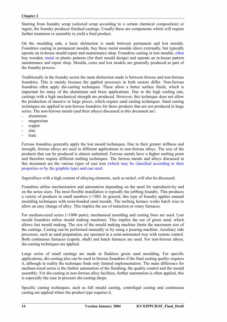
Chapter 2
14 Version January 2004 KV/EIPPCB/SF_Final_Draft
Starting from foundry scrap (selected scrap according to a certain chemical composition) oringots, the foundry produces finished castings. Usually these are components which will requirefurther treatment or assembly to yield a final product.
On the moulding side, a basic distinction is made between permanent and lost moulds.Foundries casting in permanent moulds, buy these metal moulds (dies) externally, but typicallyoperate an in-house mould repair and maintenance shop. Foundries casting in lost moulds, oftenbuy wooden, metal or plastic patterns (for their mould design) and operate an in-house patternmaintenance and repair shop. Moulds, cores and lost models are generally produced as part ofthe foundry process.
Traditionally in the foundry sector the main distinction made is between ferrous and non-ferrousfoundries. This is mainly because the applied processes in both sectors differ. Non-ferrousfoundries often apply die-casting techniques. These allow a better surface finish, which isimportant for many of the aluminium and brass applications. Due to the high cooling rate,castings with a high mechanical strength are produced. However, this technique does not allowthe production of massive or large pieces, which require sand casting techniques. Sand castingtechniques are applied in non-ferrous foundries for those products that are not produced in largeseries. The non-ferrous metals (and their alloys) discussed in this document are:- aluminium- magnesium- copper- zinc- lead.
Ferrous foundries generally apply the lost mould techniques. Due to their greater stiffness andstrength, ferrous alloys are used in different applications to non-ferrous alloys. The size of theproducts that can be produced is almost unlimited. Ferrous metals have a higher melting pointand therefore require different melting techniques. The ferrous metals and alloys discussed inthis document are the various types of cast iron (which may be classified according to theirproperties or by the graphite type) and cast steel.
Superalloys with a high content of alloying elements, such as nickel, will also be discussed.
Foundries utilise mechanisation and automation depending on the need for reproductivity andon the series sizes. The most flexible installation is typically the jobbing foundry. This producesa variety of products in small numbers (<100). In general, this type of foundry applies manualmoulding techniques with resin-bonded sand moulds. The melting furnace works batch wise toallow an easy change of alloy. This implies the use of induction or rotary furnaces.
For medium-sized series (<1000 parts), mechanised moulding and casting lines are used. Lostmould foundries utilise mould making machines. This implies the use of green sand, whichallows fast mould making. The size of the mould making machine limits the maximum size ofthe castings. Casting can be performed manually or by using a pouring machine. Auxiliary sideprocesses, such as sand preparation, are operated in a semi-automated way with remote control.Both continuous furnaces (cupola, shaft) and batch furnaces are used. For non-ferrous alloys,die-casting techniques are applied.
Large series of small castings are made in flaskless green sand moulding. For specificapplications, die-casting also can be used in ferrous foundries if the final casting quality requiresit, although in reality the technique finds only limited implementation. The main difference formedium-sized series is the further automation of the finishing, the quality control and the mouldassembly. For die-casting in non-ferrous alloy facilities, further automation is often applied, thisis especially the case in pressure die-casting shops.
Specific casting techniques, such as full mould casting, centrifugal casting and continuouscasting are applied where the product type requires it.

Chapter 2
KV/EIPPCB/SF_Final_Draft Version January 2004 15
2.1.2 Iron casting
Cast iron is an iron-carbon alloy, containing usually between 2.4 and 4 % carbon. The minimumcarbon content is 1.8 %. Silicon, manganese, sulphur and phosphorus are also present in variousamounts. Special grades of iron are produced which contain various levels of nickel, chromeand other metals. Due to its high carbon content, cast iron has a low melting point and a goodcasting ability as compared to steel. Its ductility is low and does not allow rolling or forging.Variations in properties can be achieved by varying the ratio of carbon to silicon, by alloying,and by heat treatment.
Depending on the concentration and form of the carbon (lamellar, spheroidal or compact),various types of cast iron may be defined:- lamellar iron: carbon in the form of flakes- nodular iron: carbon in spheroidal form- compact graphite iron: carbon in bonded form.
The classification of cast iron is often made according to its material properties:- grey iron: iron with a grey fracture surface. Although this applies for lamellar, nodular and
compact graphite iron, the term is commonly used as a synonym for lamellar iron- ductile iron: cast iron with an increased ductility. This is one of the effects caused by
nodularisation, but it also applies to malleable iron. The term is commonly used as asynonym for nodular iron
- malleable iron: iron that is capable of extension or of being shaped under the hammer. Thisproperty is related to a low carbon content, which leaves most of the carbon in bonded form.
Cast iron can be melted in the cupola furnace, induction furnace (generally of coreless type, butvery occasionally can be the channel type) or in the rotary furnace. The electric arc furnace isonly very rarely used for the preparation of cast iron. Figure 2.2 gives process flow diagrams forthe melting and metal treatment of cast iron in the three different furnace types. The processgenerally consists of melting – tapping – metal treatment – pouring. The various aspects ofmelting and metal treatment are discussed in the following sections. Metal treatment involvesvarious steps such as desulphurisation, nodularisation, inoculation and deslagging. Thedesulphurisation step in cupola melting may also be incorporated into the nodularisation, e.g. byusing a nodularisation process which simultaneously takes up the sulphur, such as the corewired process.

Chapter 2
16 Version January 2004 KV/EIPPCB/SF_Final_Draft
CAST IRON FOUNDRYProcess scheme with the Cupola furnace
Charging of the furnace
Melting
Tapping
Slag granulation oringotting
Pouring
Filled moulds
Moulds
Deslagging of ladlesIngotting of excessmetal
Holding of the melt
Desulphurisation
Deslagging
Nodularisation
Ladle repair
Deslagging
Deslagging
Inoculation
Preheated ladles
Preparation of the metallic charge material
Melting
Deslagging
Adjustment of thecomposition
Tapping
Pouring
Filled moulds
Preheated transferladles
Moulds
Ladle repair
Deslagging
Ingotting of excess metal
Deslagging of ladles
Nodularisation -Inoculation
Melting (intermittent rotation)
Superheating (continuousrotation)
Holding of the melt
Tapping
Nodularisation - Inoculation
Pouring
Filled moulds
Moulds
Ladle repair
Deslagging
Ingotting of excessmetal
Preheated transferladles
Deslagging of ladles
Charging of the furnace
CAST IRON FOUNDRYProcess scheme with the electric
coreless induction furnace
Preparationand weighingof the metallic
charge
Sieving andweighing
of thecoke
Weighingof
limestone
Additionof
ferroalloys
CAST IRON FOUNDRYProcess scheme with the
rotary furnace
Charging of the furnace
Preparation andweighing of themetallic charge
Preparation andweighing additions
(slagging, carb.agents)
Figure 2.2: Process flow diagrams for the melting and metal treatment of cast iron[32, CAEF, 1997]

Chapter 2
KV/EIPPCB/SF_Final_Draft Version January 2004 17
The cupola is the leading device for re-melting iron in Europe. It is responsible for some 55 %of the tonnage of iron castings produced in Western Europe. Nowadays, the cupola isincreasingly facing major challenges to its market domination. This is partially due to its flue-gas quality, which requires treatment. Faced with the possible financial burden of investing in,and then depreciating, a stack gas treatment installation, many small and medium sized unitshave turned to electric or oxygas melting units. Thus the number of cupolas used in foundries isfalling, but their average size is increasing. There have been major changes in the market forcupolas in Europe in recent years, particularly due to the restructuring of the coke industry,leading to a decreased number of suppliers and a need to import coke into Europe. Anothermajor change is the smaller number of cupola manufacturers, with one German firm having aquasi-monopoly in the hot blast type.
The majority of repetitive iron castings are made in green sand moulds with resin-bonded cores.The cold-box amine and hot-box techniques are most widely used. The ‘Croning resin shell’moulding process is used where a high precision and good surface finish are needed. The LostFoam process is used to a limited extent, for repetition castings. Castings made in smallernumbers are made in chemically-bonded sand moulds. Special sand processes, such as vacuummoulding and full moulding are used for certain iron castings. There are also a few permanentmoulding (die-casting) foundries making iron castings, but the short die-life of a mould limitingit to making only a few thousand components has restricted the use of ferrous die-casting.[156, Godinot, 2001], [174, Brown, 2000]
2.1.3 Steel casting
Steel is a material of which the (mass) content of iron is bigger than that of any other element,with a carbon content generally lower than 2%, and which also usually contains other elements.A limited number of chromium steel types may contain over 2 % carbon, but 2 % is the usualcut-off limit used to distinguish steel from cast iron [201, CEN, 2000]. One particularly usefulaspect of steel is that it can be hot worked. Low alloy cast steel contains elements such as Mn,Cr, Ni, and Mo in amounts less than 5 %. High alloy steel includes more than 5 % of alloyingelements, e.g. 12 % Cr and 8 % Ni. Special steel grades are produced with enhanced properties,such as higher strength; higher magnetic permeability; better resistance to corrosion, fatigue orwear; and improved behaviour during welding or at high or low temperatures.
Cast steel is normally melted in electric arc furnaces (EAF) or in coreless induction furnaces(IF). Once melted, the liquid metal can be refined (i.e. removal of carbon, silicon, sulphur and orphosphorus) and deoxidised (i.e. reduction of metallic oxides), depending on the base materialand the quality requirement of the finished product . Figure 2.3 gives process flow diagrams forthe melting and metal treatment of cast steel in the different furnace types.[32, CAEF, 1997]

Chapter 2
18 Version January 2004 KV/EIPPCB/SF_Final_Draft
STEEL FOUNDRYProcess scheme with the
acid lined electric arc furnace
Preparation of the charge material
Charging of the furnace
Melting
Decarburisation (oxygen injection)
Adjustment of the composition
Pouring
Filled moulds
Preheated transfer ladlesMoulds
Ladle repair
Deslagging
Ingotting of excess metal
AOD refining
Deslagging of ladles
Adjustment of the composition
STEEL FOUNDRYProcess scheme with the
basic lined electric arc furnace
DephosphorisationDecarburisation
Deslagging
Pouring
Filled moulds
Preheated transferladles
Moulds
Ladle repair
Deslagging
Ingotting ofexcess metal
Desulphurisation
Deslagging of ladles
Tapping and deoxidation
Preparation of the metallic charge material
Charging of the furnace
Melting
Deslagging
Tappingand deoxidation
Pouring
Filled moulds
Preheated transferladles
Moulds
Ladle repair
Deslagging
Ingotting of excessmetal
Deslagging of ladles
AOD/VODC refiningVacuum refining
Tapping and deoxidation
STEEL FOUNDRYProcess scheme with the
electric coreless induction furnace
Preparation of the charge material
Charging of the furnace
Melting
Adjustment of the composition
Adjustment of the composition
AOD/VODC refining
Figure 2.3: Process flow diagrams for the melting and metal treatment of steel[32, CAEF, 1997]

Chapter 2
KV/EIPPCB/SF_Final_Draft Version January 2004 19
2.1.4 Aluminium casting
About two-thirds of all aluminium castings are used in the automotive industry, e.g. in cars,buses, lorries, trains and aircraft. The need to reduce vehicle fuel consumption and weight hasincreased the interest in aluminium. The total mass of aluminium in a European car roughlydoubled between 1990 and 2000. This growing use of aluminium in its major user sector clearlyhas an effect on the overall number of castings produced.
Aluminium is mainly cast into permanent moulds. The relative shares of applied castingtechniques for Al are given in Table 2.1:
Casting type Relative share(%)
Pressure die-casting 59Low-pressure die-casting & gravity casting 37Sand casting 3Others 1
Table 2.1: Relative shares of applied casting techniques for Al[143, Inasmet and CTIF, 2002], [225, TWG, 2003]
Many different types of melting furnaces are used in aluminium foundries the choice dependingon individual requirements. Directly and indirectly heated furnaces, using fuel and electricity,are applied. The fossil fuels currently used are natural gas, liquid petroleum gas (LPG) and oil.Natural gas is favoured by most foundries on convenience grounds. Electrical heating may beprovided by either resistance elements or by induction. Capacity is one of the most importantparameters for melting and holding furnaces. Today induction furnaces are normally used whena high melting capacity, e.g. above 10 tonnes/hour, is needed. Shaft melting and holdingfurnaces, as well as crucible furnaces, are often used when the melting capacity is less than fivetonnes/hour. Small and medium crucible furnaces are often used when it might be necessary tobe able to change the alloy easily or if the production rate is low.
For holding, electric furnaces have the advantage of not producing burner off-gases and beingable to sustain a homogeneous temperature over the whole molten volume, at a relatively lowenergy expense.
Aluminium melting in foundries generally uses alloyed ingots as a starting material, although insome cases the metal is delivered already as a liquid. The secondary melting of aluminium scrapis usually not performed in foundries and falls outside the scope of this document. It isdiscussed in the BAT reference document for the non-ferrous metals industries.[48, ETSU, 1994] [148, Eurofine, 2002], [155, European IPPC Bureau, 2001]
2.1.5 Magnesium casting
Magnesium alloy castings are used for aerospace, automotive and electronic applications. Themain advantage for using them is their light weight; typically magnesium alloys have a densityof 1.8 g/ml compared with 2.7 g/ml for aluminium alloys. Aluminium is the principle alloyingconstituent of magnesium-based casting alloys, with zinc and manganese also present in smallamounts. Pressure die-casting is the most commonly used casting process, due to the lowcasting temperature (650 – 700 ºC); both hot chamber and cold chamber die-casting machinesare used. Sand moulding is applied to a lesser extent. Magnesium die-castings can be made withthinner walls than aluminium, but their use is limited by stiffness problems. The thinner wallsallow the overall weight of the components to be substantially reduced, thus compensating forthe higher alloy cost per kilogram. Gravity die-casting and sand casting are also used,particularly for more highly stressed castings. The use of magnesium alloy die-castings inautomotive components is growing rapidly, with some vehicles already containing 10 – 20 kg of

Chapter 2
20 Version January 2004 KV/EIPPCB/SF_Final_Draft
Mg components. The most popular parts made at present are instrument panel substrates, crosscar beams, wheeldrives and seat frames.
Molten magnesium alloys attack firebrick and refractory furnace linings, resulting in harmfulsilicon contamination. Therefore steel crucibles are used. Iron is also slightly soluble inmagnesium but it has a much less harmful effect than silicon. Scrap is usually cleaned and ifpossible shot blasted to remove any adhering sand as a further precaution against silicon pick-up. To eliminate ladling, the molten alloy is, if possible, poured direct from the melting pot.
Due to its very easy oxidation, magnesium alloys are melted under a cover using a cleansingflux or cover gas, to avoid oxidation losses and to prevent inclusions. Inhibitor powders are usedto cover any exposed metal during holding and pouring, and are added to moulding-sand toprevent chemical reactions. The fluxless melting of Mg alloys requires another form of meltprotection. For this purpose, sulphur hexafluoride (SF6) is used, as it promotes the formation ofa protective film on liquid magnesium, which prevents oxidation. It is used at low concentration(<0.3 vol %) in a mix with air or air/CO2. SF6 is a greenhouse gas, considered harmful to theatmosphere and falls under the Kyoto protocol, which requires its use to be minimised. Austriaand Denmark have issued regulations to ban the use of SF6 by 2003 and 2006, respectively.
Magnesium alloys benefit from grain refinement, which is carried out by inoculation withcarbonaceous materials. This used to be done with hexachloroethane, but since 1 July 2003 thisproduct is banned in Europe generally to ensure environmental protection and for health andsafety reasons. This applies both for magnesium and aluminium alloys.[175, Brown, 1999], [225, TWG, 2003]
2.1.6 Copper casting
Copper is cast in the form of various groups of alloys, each having copper as the main element.Short descriptions of some of these are given below:
- High conductivity coppers: These are used mainly for their high electrical and thermalconductivities. Applications include tuyères for blast furnaces and hot blast cupolas, water-cooled electrode clamps, switchgear, etc.
- Brasses: Cu-Zn-alloys, where zinc is the major alloying element. These are easy to cast,with excellent machinability and good resistance to corrosion in air and fresh water. Theyare widely used for plumbing fittings. High tensile brasses are more highly alloyed and finduses in marine engineering. Brasses are cast both in sand and in permanent moulds
- Tin bronzes: Cu-Sn-alloys, where tin is the major alloying element. With tin contents of10 – 12 %, tin bronze castings are more expensive than brass. They have high corrosionresistance and are suitable for handling acidic waters, boiler feed-waters, etc. High tin alloysare also used in wear-resistant applications. Their applied casting techniques are sand andcentrifugal casting
- Phosphor bronzes: Cu-Sn-alloys, with an addition of about 0.4 – 1.0 % P. These are harderthan tin bronzes but have lower ductility. They are used for bearings where loads andrunning speeds are high and for gears such as worm wheels
- Lead bronzes: Cu-Sn-Pb-alloys. These are used almost exclusively for bearings, whereloads and speeds are moderate
- Gunmetals: Cu-Sn-Zn-Pb-alloys. These are the optimal alloys for sand casting. They have agood combination of castability, machinability and strength, and good corrosion resistance.They are used for intricate, pressure-tight castings, such as valves and pumps. They are alsoused for bearings, where loads and speeds are moderate
- Aluminium bronzes: Cu-Al-alloys, where Al is the major alloying element. These combine ahigh strength with high resistance to corrosion. Their applications range from decorativearchitectural features to highly stressed engineering components. They have many marineuses, including propellers, pumps, valves. They are also used for the manufacture of non-sparking tools. Al casting techniques are applied
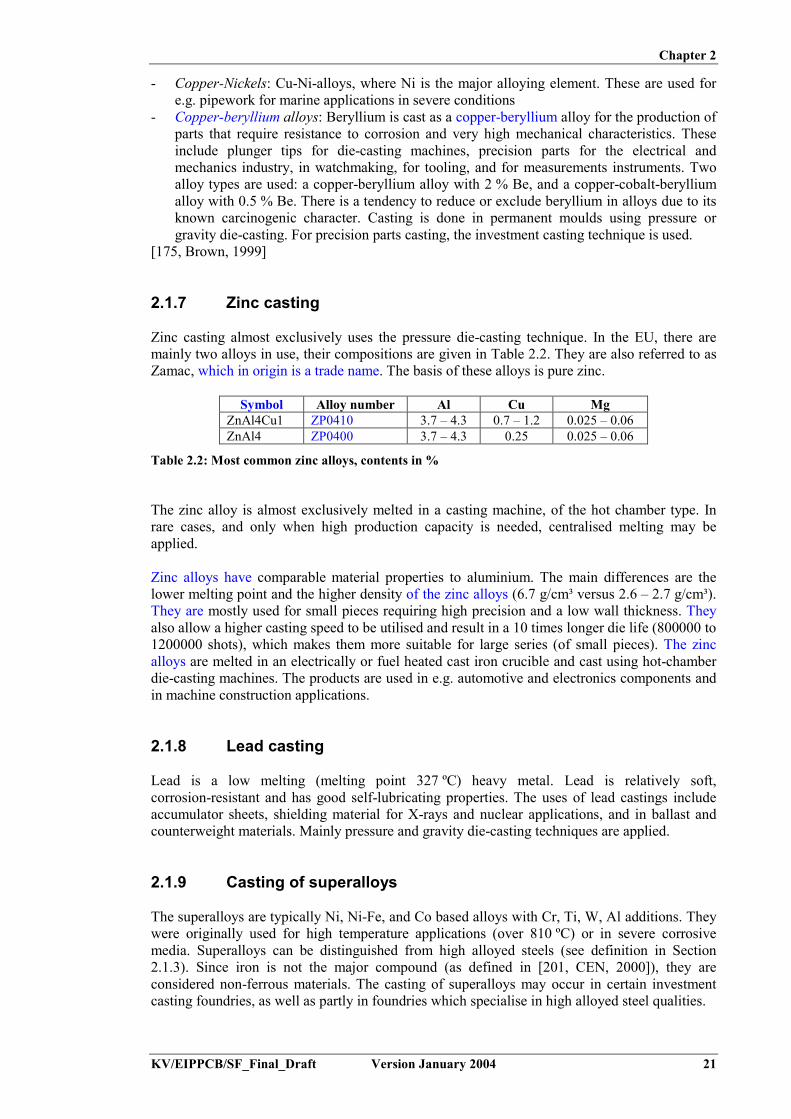
Chapter 2
KV/EIPPCB/SF_Final_Draft Version January 2004 21
- Copper-Nickels: Cu-Ni-alloys, where Ni is the major alloying element. These are used fore.g. pipework for marine applications in severe conditions
- Copper-beryllium alloys: Beryllium is cast as a copper-beryllium alloy for the production ofparts that require resistance to corrosion and very high mechanical characteristics. Theseinclude plunger tips for die-casting machines, precision parts for the electrical andmechanics industry, in watchmaking, for tooling, and for measurements instruments. Twoalloy types are used: a copper-beryllium alloy with 2 % Be, and a copper-cobalt-berylliumalloy with 0.5 % Be. There is a tendency to reduce or exclude beryllium in alloys due to itsknown carcinogenic character. Casting is done in permanent moulds using pressure orgravity die-casting. For precision parts casting, the investment casting technique is used.
[175, Brown, 1999]
2.1.7 Zinc casting
Zinc casting almost exclusively uses the pressure die-casting technique. In the EU, there aremainly two alloys in use, their compositions are given in Table 2.2. They are also referred to asZamac, which in origin is a trade name. The basis of these alloys is pure zinc.
Symbol Alloy number Al Cu MgZnAl4Cu1 ZP0410 3.7 – 4.3 0.7 – 1.2 0.025 – 0.06ZnAl4 ZP0400 3.7 – 4.3 0.25 0.025 – 0.06
Table 2.2: Most common zinc alloys, contents in %
The zinc alloy is almost exclusively melted in a casting machine, of the hot chamber type. Inrare cases, and only when high production capacity is needed, centralised melting may beapplied.
Zinc alloys have comparable material properties to aluminium. The main differences are thelower melting point and the higher density of the zinc alloys (6.7 g/cm³ versus 2.6 – 2.7 g/cm³).They are mostly used for small pieces requiring high precision and a low wall thickness. Theyalso allow a higher casting speed to be utilised and result in a 10 times longer die life (800000 to1200000 shots), which makes them more suitable for large series (of small pieces). The zincalloys are melted in an electrically or fuel heated cast iron crucible and cast using hot-chamberdie-casting machines. The products are used in e.g. automotive and electronics components andin machine construction applications.
2.1.8 Lead casting
Lead is a low melting (melting point 327 ºC) heavy metal. Lead is relatively soft,corrosion-resistant and has good self-lubricating properties. The uses of lead castings includeaccumulator sheets, shielding material for X-rays and nuclear applications, and in ballast andcounterweight materials. Mainly pressure and gravity die-casting techniques are applied.
2.1.9 Casting of superalloys
The superalloys are typically Ni, Ni-Fe, and Co based alloys with Cr, Ti, W, Al additions. Theywere originally used for high temperature applications (over 810 ºC) or in severe corrosivemedia. Superalloys can be distinguished from high alloyed steels (see definition in Section2.1.3). Since iron is not the major compound (as defined in [201, CEN, 2000]), they areconsidered non-ferrous materials. The casting of superalloys may occur in certain investmentcasting foundries, as well as partly in foundries which specialise in high alloyed steel qualities.

Chapter 2
22 Version January 2004 KV/EIPPCB/SF_Final_Draft
The nickel base alloys are produced from a group of alloys which have chemical compositionsgenerally over 50 % nickel and less than 10 % iron. They are mainly strengthened byintermetallic precipitation in an austenitic matrix. The cobalt base alloys have a high Co content(40 to 70 %), high Cr (over 20 %), high W (7 to 15 %) and they are strengthened by acombination of carbides and solid solution hardeners.
Some superalloys, particularly Ni-Fe and Co based alloys, are directly melted in electricfurnaces by classical methods usually applicable to stainless steels. However for Ni and specialNi-Fe superalloys, vacuum induction melting is required in order to reduce the content ofinterstitial gases (O, H, N) to a very low level. This enables foundries to achieve high andcontrolled contents of oxidisable elements such as Ti or Al.
The control of interstitial gases and oxidisable elements is very important for the product’smechanical properties, the corrosion resistance and its reliability. In general, superalloys are castinto complex final shapes where machining is not possible. Therefore, they are mainly producedby investment casting (i.e. using a ceramic mould). This casting process produces a product ofvery precise dimensions with a very smooth surface. Additional processes, such as HIP (hotisostatic pressing), can be used to eliminate the internal porosity that can appear in largecastings. In aircraft gas turbine manifolds, directional casting technology is commonly applied.This technology eliminates the grain boundaries and greatly increases the strength of thematerial.
Initially superalloys were developed for high temperature applications. However, their field ofapplication continues to expand and now covers areas such as cryogenic temperature appliancesand orthopaedic and dental prostheses. In general, superalloys are mainly used in aircraft andindustrial gas turbines, in nuclear reactors, in aircraft and spacecraft structures, in petrochemicalproduction and in medical applications.[202, TWG, 2002]
2.2 Pattern making
2.2.1 General pattern making
Pattern making, or foundry tooling as it is also called, requires a high level of skill to achievethe close tolerances required of the patterns and coreboxes. This step is critical in the castingprocess since the castings produced can be no better than the patterns used to make them.Patterns are made by means of hand tools, universal machines, or by a CAD/CAM system oncomputer-numerical-controlled (CNC) machines. In some pattern making shops, computer-aided design (CAD) is used in the design of patterns. Cutter tool paths are designed withcomputer-aided manufacturing (CAM). The numerical output from these computers is conveyedto CNC machine tools, which then cut the production patterns to shape. Such computer-aidedsystems have better dimensional accuracy and consistency than manual methods.
Patterns (Figure 2.4) and corebox materials (Figure 2.5) are typically metal, plastic, wood orplaster. Wax and polystyrene are used in the investment and Lost Foam casting processes,respectively. Pattern makers have a wide range of tools available to them, includingwoodworking and metal machining tools. Mechanical connectors and glues are used to joinpattern pieces together. Wax, plastic or polyester putty is used as a filler to fill or round theinside of square corners.[42, US EPA, 1998]

Chapter 2
KV/EIPPCB/SF_Final_Draft Version January 2004 23
Figure 2.4: Wooden pattern[237, HUT, 2003]
Figure 2.5: Coreboxes[237, HUT, 2003]
2.2.2 Rapid prototyping (RP)
Rapid prototyping is a technique to pass very quickly from a product concept to a castprototype. The term ‘Rapid Prototyping’ includes all technical and organisational measuresfrom the formulation of the concept of a product to the manufacture of the product. Rapidprototyping can be used for every stage of product development, i.e. for concept models,geometrical prototypes, functional prototypes or for technical or sales prototypes. All thecurrently available techniques allow the fabrication of a prototype part from a three-dimensionaldrawing. They are also used for the direct sintering of sands for the production of moulds orcores. The technique consists of building an object to a design pattern by joining particles orlayers of raw material such as polymer resin, wax, paper or ceramic powder. An examplepicture of a wax pattern is given in Figure 2.6

Chapter 2
24 Version January 2004 KV/EIPPCB/SF_Final_Draft
Figure 2.6: Thermopolymer (wax) patterns in an RP machine[237, HUT, 2003]
There are 4 basic steps to rapid prototyping:1. the creation of a 3D-CAD model2. making the interface between the 3D-CAD system and the rapid prototyping system. For
example the CAD data may be converted to the STL (Standard transformation format) fileformat
3. slicing the STL file into thin cross–sectional layers4. realisation of the RP-model.
The advantages of Rapid Prototyping, particularly for complex forms, include:- shorter development time and the possibility of rapid modifications during the development- saving of costs, materials and time- early error detection.[202, TWG, 2002], [203, Linxe, 2002]
A survey of available techniques is given in Table 2.3.
Process Principle Materials Special featuresLiquid – solid Polymerisation by local UV
exposure of a photosensitiveresin
Photosensitive resinsAcrylates, epoxydes
- shrinkage anddeformations
- model needssupports
Solid – solid Contours of a layer are cut outfrom a foil
Paper, metals, polymers - no supports- consumption of
base materialDeposition of a materialshowing thermal fusion
ABS, wax, elastomers - model needssupports
Material jet Waxes, polymers - model needssupports
Powder – solid Agglomeration of powder bysintering
Metals, ceramics, sand,polystyrene, nylon,polyamide, wax
- no supports- porosity- shrinkage
Agglomeration of powder bybinder projection
Alumina - no supports- porosity
Table 2.3: Description of rapid prototyping techniques[203, Linxe, 2002]

Chapter 2
KV/EIPPCB/SF_Final_Draft Version January 2004 25
2.3 Raw materials and raw material handling
The main flows of raw materials entering the foundry are metal ingots, foundry scrap and sand.A distinction can be made between ferrous and non-ferrous foundries. Non-ferrous foundriesgenerally melt only internal return material and alloy ingots (Figure 2.7). The re-melting ofexternal scrap is generally considered a separate activity, usually forming part of the secondarymetal production. If external scrap is acquired, it is first subjected to a spectroscopy analysis inorder to determine the alloy type. Ferrous foundries use pig iron and selected iron and steelscrap as starting materials, besides internal return material. The various qualities of metal feedsare stored in separate areas in order to allow the controlled feeding of the melting furnace.
Figure 2.7: Aluminium scrap(l.) and ingots (r.)[237, HUT, 2003]
Raw materials, including fluxes in lump and powder form; foundry cokes for cupola furnaces;deoxidants; and refractories are normally stored under cover. Following delivery, handling iskept to a minimum. Powdered materials may be stored in sealed silos and conveyedpneumatically or kept and handled in sealed bags, as displayed in Figure 2.8.
Figure 2.8: Pneumatic conveyors and silos for powdered materials[237, HUT, 2003]
Sand is normally delivered in bulk and discharged directly to a silo via a pneumatic conveyor,conveyor belt or grab. Specialist sands may arrive in bags or by tanker. Used sands are stored insilos for regeneration and in silos or heaps for transport for external re-use or disposal.
Liquid binders and oil products are delivered in drums, by bulk container or by road tanker.They are stored in their delivery containers or, in the case of rail tankers, discharged direct intoa dedicated storage. The containers are connected by pipe directly to the sand/resin/catalyst-mixing unit. Some catalysts and co-reactants are used in a gaseous form, but these are also

Chapter 2
26 Version January 2004 KV/EIPPCB/SF_Final_Draft
delivered as liquids and handled in a similar fashion before being vaporised and mixed with acarrier gas. Evaporation is enclosed and may be carried out by a variety of methods.
Refractories, release agents and other minor deliveries are stored indoors.
Coarse solid residues, such as used refractories and slags, are stored on separate heaps, in asubdivided storage area or in boxes. They are moved and handled using small lift trucks. Finesolid residues are collected at the filter unit into big bags or containers, which may be storedintermediately before transport for disposal. In order to avoid soil contamination from thevarious classes of materials, specific measures are taken. Potential impacts are listed in Table2.5.
The metal charged in the melting furnace is carefully selected and weighed to ensure the correctcomposition. The charge composition is calculated based on the average chemical compositionof each component, the oxidation losses during melting and the required final composition ofthe casting. The different charge elements are combined into a charging device (e.g. dropbottom skip, vibrating feeder, skip hoist) with a tilting magnet, usually equipped with aweighing system, to allow collection of the correct amount.
Additional alloying elements can be added to the charge as ferro-alloys such as FeSi, FeMn,FeCr, or pure such as Cu, C, Ni. However most alloys are added to the molten metal to preventmetallic losses due to oxidation. Alloying elements are usually present in the foundry in smallquantities and are always stored inside the building, preferably close to the melting installation.[32, CAEF, 1997].

Chapter 2
KV/EIPPCB/SF_Final_Draft Version January 2004 27
Activities Contaminants of Concern Potential ImpactRaw materials storage
Loose materials from scrap - metalsand coatings
Localised contamination ofsoil surface
Oils - may include:- PAH from combustion engine oils- PCBs from capacitors (mainly inshredded scrap, unless PCB phase-outhas taken place successfully)
Scrap storage – external, oftenon soil
Cutting fluids - may be chlorinated
Leaching into groundwaterand nearby surface waters
Liquids in underground tanks Petroleum products, e.g. fuel oildiesel
Leakage into soil withleaching into ground andsurface waters
Raw materials handling, transfer and useChemical binder products –accidental spillage or leaks
Phenolic resins Free phenol contentof 0.5 to 5 %
Water-soluble; can leachinto groundwater.Rapid degradation if lessthan 400 ppm.Concentrated larger volumespills will be slower todegrade due to toxicity tobacteria
Solvent carriersin resins
e.g. methanol, upto 20 % volume
Mostly water-soluble, canleach into groundwater
Urethane resins Aromatic solvents1 Solvents could leach intogroundwater
Furan hardeners Toluene-, Xylene-,Benzene-sulphonicacids
Could leach intogroundwater or alter soilproperties, e.g.mobilisation of metals
Urea-basedresins
Ammonia Can leach into ground andsurface waters
Silicate resins Alkaline pH Could leach intogroundwater or alter soilproperties, e.g.mobilisation of metals
Mould coatings Isopropyl alcohol (IPA) Water-soluble, can leachinto groundwater
Fuels, maintenance products:- accidental spillage or leaks(particularly around fillingpoints)- deliberate disposal to ground
Fuel oils, diesel, petrol with PAH &SO4
2- post-combustion;Lubrication & hydraulic oils;Quench oils;Transformer oils (potential for PCBs)
Oils can leach into groundand surface waters.Air deposition of PAH andSO4
2- from the combustionof fuel oils.SO4
2- will leach down soilprofile.PAH, PCBs will tend toabsorb onto soils
1 Former formulations contained PAH (mainly naphtalene), but naphtalene depleted formulationshave been developed, which have eliminated this contaminant.
Table 2.4: Potential soil contamination from ferrous foundry raw materials[140, EU Thematic Network Foundry Wastes, 2001], [225, TWG, 2003]

Chapter 2
28 Version January 2004 KV/EIPPCB/SF_Final_Draft
2.4 Melting and metal treatment
The selection of a melting furnace is an important aspect in the setting up of a foundry process.Each furnace type has its own properties concerning feed requirements and alloyingpossibilities, which in turn will have repercussions on the full foundry process. On the otherhand, the type of metal to be melted determines which furnace may or may not be used. Theapplicability of the various furnace types is given in Table 2.5.
Cupola Electric arc Channelinduction
Corelessinduction
Rotary Hearth type Shaft Crucible/Ladle
Iron m m* h m, h m* m hSteel m m hAluminium m, h m, h m m m m, hMagnesium m, hCopper h m, h m m, hLead m, h m, hZinc m, h m, h* Less common
Table 2.5: Applicability of furnace types, for melting (m) and holding (h)
Iron foundries require metal of a controlled composition and temperature, supplied at a ratesufficient to match the varying demand of the moulding line. The metallic charge to be meltedusually consists of foundry returns, iron and steel foundry scrap and pig iron, with alloyingadditions such as e.g. ferrosilicon, ferrophosphorus or ferromanganese. The charge is usuallymelted in a cupola or in an electric induction furnace. Induction furnaces are gradually gaininghigher market preference compared to the cupola type. Coreless induction furnaces are used formelting. Channel induction furnaces are only used for holding, their main application being incombination with the cupola furnace, in the so-called duplex configuration. Gas-fired and oil-fired rotary furnaces can also be used, although their use is less common. Short-term holding,transport and metal treatment are performed in ladles.
Steel is melted in both electric arc and induction furnaces. Large steel foundries may use electricarc furnaces, but induction furnaces are more commonly used. Arc furnaces are capable of usinglow cost scrap charges, since refining takes place in the furnace. However, they have thelimitation that there is always some carbon pick-up from the graphite electrodes, so very lowcarbon stainless steels (<0.03 % �C) cannot be made. In the induction furnace, refining is notpossible, so a carefully selected charge must be used. However, any type of steel may be melted.Short-term holding, transport and metal treatment are performed in ladles.
The melting furnace used in non-ferrous melting is dependent on the foundry size. Non-ferrousfoundries often use a variety of different alloys and/or have a limited melting capacity. Meltingis done in small volume furnaces, for which the crucible furnace is most suited. Additionally,die-casting is the major casting technique. In this case, there often is no need for a centralisedmelting, as the melting (and holding) furnace is integrated into the casting machine. Non-ferrousfoundries with a higher capacity and a need (or reason) for centralised melting typically useinduction, hearth type or shaft furnaces for melting, and then distribute the molten metal toholding furnaces and casting crucibles.[174, Brown, 2000], [225, TWG, 2003]
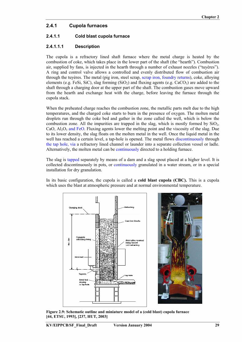
Chapter 2
KV/EIPPCB/SF_Final_Draft Version January 2004 29
2.4.1 Cupola furnaces
2.4.1.1 Cold blast cupola furnace
2.4.1.1.1 Description
The cupola is a refractory lined shaft furnace where the metal charge is heated by thecombustion of coke, which takes place in the lower part of the shaft (the “hearth”). Combustionair, supplied by fans, is injected in the hearth through a number of exhaust nozzles (“tuyères”).A ring and control valve allows a controlled and evenly distributed flow of combustion airthrough the tuyères. The metal (pig iron, steel scrap, scrap iron, foundry returns), coke, alloyingelements (e.g. FeSi, SiC), slag forming (SiO2) and fluxing agents (e.g. CaCO3) are added to theshaft through a charging door at the upper part of the shaft. The combustion gases move upwardfrom the hearth and exchange heat with the charge, before leaving the furnace through thecupola stack.
When the preheated charge reaches the combustion zone, the metallic parts melt due to the hightemperatures, and the charged coke starts to burn in the presence of oxygen. The molten metaldroplets run through the coke bed and gather in the zone called the well, which is below thecombustion zone. All the impurities are trapped in the slag, which is mostly formed by SiO2,CaO, Al2O3 and FeO. Fluxing agents lower the melting point and the viscosity of the slag. Dueto its lower density, the slag floats on the molten metal in the well. Once the liquid metal in thewell has reached a certain level, a tap-hole is opened. The metal flows discontinuously throughthe tap hole, via a refractory lined channel or launder into a separate collection vessel or ladle.Alternatively, the molten metal can be continuously directed to a holding furnace.
The slag is tapped separately by means of a dam and a slag spout placed at a higher level. It iscollected discontinuously in pots, or continuously granulated in a water stream, or in a specialinstallation for dry granulation.
In its basic configuration, the cupola is called a cold blast cupola (CBC). This is a cupolawhich uses the blast at atmospheric pressure and at normal environmental temperature.
Figure 2.9: Schematic outline and miniature model of a (cold blast) cupola furnace[44, ETSU, 1993], [237, HUT, 2003]

Chapter 2
30 Version January 2004 KV/EIPPCB/SF_Final_Draft
In order to reduce the CO-emission and increase the energy efficiency, the conversion of coldblast furnaces to hot blast furnaces may be considered (see Section 4.5.2). However, formedium-sized foundries handling less than 2000 tonnes/month of good castings, the hot blastcupola will be difficult to consider because of the large investment it requires. The use of a hotblast cupola is also restricted to continuous melting, otherwise the running costs are too high.The cold blast cupola prevails for some types of production, e.g. enamelled iron castings,kitchenware, heating appliances, counterweights. These types of castings allow a high level ofold cast irons to be used in the melting bed; a charge material still plentiful in the countries ofthe old industrial Europe and one that is well suited to the cold blast cupola.[44, ETSU, 1993], [156, Godinot, 2001], [202, TWG, 2002]
2.4.1.1.2 Maintenance
One specific feature of the cupola furnace is that the lining material (quartz-clay-mixture) of thefurnace at the melting and heating zone only lasts for one melting campaign. The intense heatand the presence of slag results in a chemical dissolution and mechanical wearing of the lining,which consequently converts it into slag. Cupola furnaces are therefore normally constructed inpairs. While one furnace is melting, the second one can be lined with new refractory material,with the operation being switched around the next day of use.[110, Vito, 2001]
2.4.1.1.3 Advantages:
- the investment cost is EUR 125000 – 150000 per tonne installed per hour, inclusive of adedusting installation
- different kinds of (cheap) scrap can be used due to the cleaning and carburising operation- the thermal efficiency is acceptable if appropriate measures are utilised.
2.4.1.1.4 Disadvantages:
- the production regime is not flexible- difficult production management because of the slowness of the system- expensive charge with pig iron, and little steel scrap- no quick alloy change possible- sulphur pick-up/take-up in the cupola- an environmental burden is caused by the foundry; i.e. lots of dust, slag and refractory
lining- big dedusting installations are needed because of the high flue-gas rate.[110, Vito, 2001]
2.4.1.2 Hot blast cupola furnace
2.4.1.2.1 Description
In order to optimise the efficiency of the cupola furnace, the combustion air may be preheated.This principle is used in the hot blast cupola (HBC), i.e. a cupola which uses a preheated blast.
The advantages of the hot-blast operation may be summarised as follows:- reduced coke consumption- increased metal temperature- increased melting rate- reduced sulphur pick-up- reduced melting losses- increased carbon pick-up and hence the ability to substitute steel scrap for pig iron in the
furnace charge.

Chapter 2
KV/EIPPCB/SF_Final_Draft Version January 2004 31
It should be noted that not all these advantages can be attained at the same time. For example,an increase in the proportion of steel scrap in the furnace charge may require an increase in theproportion of coke for recarburisation; this in turn will reduce the melting rate and increase thesulphur pick-up.
Two methods of heating are:- Recuperative heating: This involves the transfer of the residual (“latent”) heat of the flue-
gases to the combustion air. The flue-gases are collected at the top of the furnace, mixedwith sufficient air and then burned in a post combustion unit. This provokes the exothermicoxidation of CO. The burnt gases are led through a heat-exchanger (recuperator) where theheat is transferred to the combustion air. Typically the blast air is heated at temperatures of500 to 600 ºC. Above these temperatures, problems arise with the sintering of furnace duston the surface of the recuperator
- External heating: Here the combustion air is heated by some external means, e.g. by a gasor fuel burner, by electrical resistance or by a plasma torch.
The combination of these two heating methods, permits the superheating of the blast air up to1000 ºC. These high temperatures, however, require the use of more expensive refractorymaterials and may cause too high a melt temperature.
Recuperative systems offer increased energy and thermal efficiencies. The effect of airpreheating on thermal efficiency and coke use is depicted in Figure 2.10. It should be noted thatthe coke quality may affect the overall blast efficiency.
Figure 2.10: Effect of air preheating on blast furnace efficiency[44, ETSU, 1993]
For medium-sized foundries producing up to 2000 tonnes/month of good castings, the hot blastcupola is difficult to consider, in particular because of the large investment it requires. In theseinstances, the cold blast cupola prevails for some types of production. The hot blast cupolaremains the most widely applied melting device for mass production foundries, e.g. for parts forthe automobile industry, centrifugal casting, road accessories.Hot blast cupolas are normally set up for long campaign operation, in order to minimise processswitch overs and maintenance time and effort.[32, CAEF, 1997], [44, ETSU, 1993], [156, Godinot, 2001]

Chapter 2
32 Version January 2004 KV/EIPPCB/SF_Final_Draft
2.4.1.2.2 Advantages:
- reduced coke consumption- high tap temperature- high melting capacity- less sulphur pick-up in the cupola- possibility to use different kinds of cheap lower grade ferrous scrap- more scrap steel can be used because of the higher pick-up of the carbon by pig iron.
2.4.1.2.3 Disadvantages:
- very expensive investment, due to the additional environmental measures required- production regime is not flexible- difficult production management because of the slowness of the system- limited to iron alloys only, no quick alloy change possible- environmental burden caused by the foundry, e.g. lots of dust, slag and refractory lining- big dedusting installations are needed because of the high flue-gas rate.[110, Vito, 2001]
2.4.1.3 Long campaign cupola
A long campaign cupola is usually a water-cooled refractory lined cupola that may be hot blastor cold blast. Such cupolas are operated daily for one, two or three shifts and are very often usedonly as a single unit. This form has a campaign life of several weeks or months. The lininglesscupola allows a much longer campaign life but heat losses through the furnace shell can besignificant. Further developments in refractories and operating practices are continually beingmade which improve the life and cost effectiveness of the long campaign cupola. A schematicrepresentation of a long campaign cupola with an in-shaft afterburner is given in Figure 2.11.
Figure 2.11: Schematic representation of a long campaign cupola[150, ETSU, 1998]

Chapter 2
KV/EIPPCB/SF_Final_Draft Version January 2004 33
To allow for long campaign operation the following measures need to be taken:- apply a more persistent refractory lining of the shaft, bottom and the hearth- apply water cooling of the furnace wall: this keeps the wall temperature low and thus
prevents rapid wearing of the hearth lining- use water-cooled blasting pipes that penetrate deeper into the furnace shaft. Here, the
combustion zone is not in direct contact with the furnace lining. Water-cooling has alsobeen used for reasons other than only reducing the consumption of refractories, such as:� to extend the duration of the melt� to enable the internal diameter of the furnace to be increased, thus allowing a higher
melting rate.
In the liningless operation, the charge is in direct contact with the water-cooled steel furnaceshell. Liningless operation is only used on relatively large capacity cupolas, melting for longcampaigns. This results in the following advantages:- only one cupola is required- the cupola only requires internal repairs after one, or several, week’s operation- daily bed-coke consumption is reduced- monitoring is easier throughout the campaign, because of the constant diameter and the
more consistent melting conditions.
A specific type of long campaign cupola is the cokeless cupola. This is discussed in Section4.2.1.8.[32, CAEF, 1997], [44, ETSU, 1993], [110, Vito, 2001], [150, ETSU, 1998]
2.4.1.4 Nature of atmospheric emissions
Cupolas can be charged with a wide range of materials, many of which may contain looseparticles such as rust, sand and non-ferrous materials. The metallurgical-coke can break andproduce small pieces, as can the added fluxing materials. Breakage and mechanical abrasionduring charge preparation, as well as during charging itself, generate particles, some of whichare immediately emitted.
During melting, abrasion of the charge against the refractory lining will also generate dust.
A third source of particulate matter is coke ash, generated in the melting zone, which is nottrapped by the slag phase.
Particulate matter of various sources, if light enough, can be entrained in the combustion gasesof the cupola. Under certain conditions metallurgical-fume may be generated from the meltingzone, leading to a visible plume from the cupola stack. The smoke particles consist ofsubmicron agglomerates of spherical soot particles and metallic oxides, such as ZnO, PbO, etc.,if the metals are present in the charged steel or iron scrap, such as in galvanised or paintedscrap. The smoke emission will increase with the proportion of coke and contaminants in thecharge, the blast temperature, and the oxygen injection rate.
Carbonaceous smoke is airborne matter formed by the incomplete combustion of organic matterin the cupola. Scrap contaminants such as oil and grease, wood, textiles and, rubber will formoily vapours in the stack gases. Vapours and partially burnt organic matter may carry unpleasantsmells.
Again, scrap cleanliness and its nature significantly effect the nature of the emissions. Theburning of coke creates odorous gas emissions containing CO2, CO and SO2. Decreasing theproportion of the coke charge (by increasing the thermal efficiency) or (partial or complete)substitution of the coke by natural gas can help reduce the levels of these substances.

Chapter 2
34 Version January 2004 KV/EIPPCB/SF_Final_Draft
2.4.2 Electric arc furnace (EAF)
2.4.2.1 Description
The EAF is a batch-melting furnace consisting of a large bowl shaped refractory lined bodywith a dish shaped hearth. The wide furnace shape allows the handling of bulky charge materialand leads to efficient reactions between the slag and metal. Typically the shell diameter is 2 to4 m. As shown in Figure 2.12, the furnace is covered by a refractory roof, which has ports forthree graphite electrodes. The electrodes are supported by arms, which allow movement up anddown. Most furnaces use roof charging: by moving the roof and electrodes aside, the furnacecan be charged using a drop bottom charging bucket or a magnet. The metal charge is heated byan electric arc, which is created by a three phase alternate electrical current between the threegraphite electrodes. These are positioned above the charge, which itself acts as the neutral.
Figure 2.12: EAF furnace[237, HUT, 2003]
The furnace is tapped by tilting it, forcing the metal to flow out through the spout. Opposite thespout, an operable door allows deslagging and sampling operations to be carried out prior totapping.
The lining of the furnace may be acidic (SiO2 based refractory) or basic (MgO based refractory).A basic lining allows the use of virtually all kinds of steel scrap. The furnace can also be usedfor the production of high alloy and manganese steels. If scrap with high phosphor or sulphurconent is used, lime and limestone which are usually added for dephosphorisation anddesulphurisation. An acidic lining would be attacked by these compounds. Therefore, the acidictype refractory is used for melting scrap with a low sulphur or phosphorus content only.
Electric arc furnaces are almost exclusively used for the melting of steel. Only in a few cases arethey used for cast iron production, which requires an addition of coal dust to the melt. Electricarc furnaces designed for steel foundries' purposes usually range from 2 to 50 tonnes capacities.They can be run intermittently and are suitable for a wide range of steel analyses. They canprovide steel at high temperatures, with typical meltdown times of about one to two hours,while achieving high thermal efficiencies of up to 80 %1. Power consumption varies from 500 to800 kWh/tonne of molten steel, depending on the furnace capacity, the hot metal consumption,and the refining techniques, tapping temperature and pollution control equipment applied. Thetotal melt time is typically 1 to 4 hours.
1 Without taking into account the efficiency of electric power generation.

Chapter 2
KV/EIPPCB/SF_Final_Draft Version January 2004 35
2.4.2.2 Melting and refining with the acidic lined EAF
Due to the chemical nature of the acid lining (SiO2), the refining abilities of this type of furnaceare restricted to decarburisation. Consequently considerable care has to be exercised in selectingthe charge for acceptable sulphur and phosphorus levels, as these cannot be removed in the acidmelting practice. The charge consists of balanced quantities of pig iron, foundry returns andpurchased scrap. The carbon in the charge is held at a high enough level so that after melting itis 0.2 to 0.4 % above the final level.
The decarburisation starts by injecting oxygen into the metal bath. This creates a strong stirringaction during which carbon in the melt is burned. At the same time the “boiling” burns out Si,and flushes out H2 and N2 from the metal bath. All impurities (oxides) are trapped in the slag.During melting, sand (SiO2) may be added to bring the slag to the proper consistency. When thecarbon reaches the proper concentration, oxygen injection is stopped, and silicon andmanganese are added to halt the boiling reaction.
After slag removal the metal composition is controlled and adjusted if necessary. Finally themetal is deoxidised by adding aluminium or other agents into the melt stream during tapping, toprevent the formation of CO bubbles during solidification. Additional desulphurisation and ordephosphorisation refining can be executed in an AOD or VODC converter (see Section 2.4.9and 2.4.10).[32, CAEF, 1997], [161, UK Environment Agency, 2002]
2.4.2.3 Melting and refining with the basic lined EAF
The alkaline MgO based lining of this EAF makes it possible to refine the metal in the furnaceitself. Therefore it is possible to charge the furnace with virtually any combination of scrap andfoundry returns. The basic lining practice is used when the purchased scrap contains higherphosphorus and/or sulphur levels than desirable.
Dephosphorisation of the melt is performed by periodic additions of lime during meltdown.Upon the injection of oxygen in the bath, phosphorous oxide is formed and trapped in the slag,together with other metallic oxides and impurities. The lime keeps the slag very basic, whichstabilises the phosphorous oxide. At the same time carbon is burnt out. After sufficient reactiontime, the oxygen injection is stopped and the slag is fully removed.
Desulphurisation takes place in a second stage, in a similar way but at a higher temperature.Again, lime or limestone is added to the melt, reacting with sulphur to form insoluble CaS, thatis trapped by the slag. Periodic additions of carbon, aluminium, or FeSi reduce the metallicoxides (e.g. manganese-, chromium oxides), and thereby minimise losses of these elementsfrom the metal bath. All other impurities (oxides) are trapped in the slag and removed during thefinal deslagging operation.
After refining the metal composition is controlled and adjusted if necessary. Finally the metal isdeoxidised by the addition of aluminium or other agents in the metal bath prior to tapping, toprevent the formation of CO bubbles during solidification. Further metal treatment, using anAOD or VODC converter (see Section 2.4.9 and 2.4.10) may be applied if the final alloycomposition requires it.[32, CAEF, 1997], [161, UK Environment Agency, 2002]
2.4.2.4 Nature of atmospheric emissions
The emissions from EAFs originate from the charging, melting, and refining operations andduring tapping of the furnace.

Chapter 2
36 Version January 2004 KV/EIPPCB/SF_Final_Draft
During charging, dust and dirt will be emitted from the open furnace body. When charging a hotfurnace (for instance when melting with a molten heel in particular), any combustibles such asgrease, paint or oil ignite and give rise to smoke plumes of burnt and partially burnt organicmaterial and dust particles. The mechanical abrasion of the furnace lining also generatesadditional dust.
During melting, heating of the scrap generates metal oxide fumes that significantly increaseduring the decarburisation treatment. The injection of oxygen gas into the molten metaldevelops significant quantities of iron oxide fumes, which leave the furnace as red clouds. Theaddition of slag forming materials increases the furnace emission, but only in small quantitiesand only for a short time.
Minor emissions occur during the transfer of the molten metal into a ladle or holding furnace.
Emissions from the melting operation itself are referred to as primary emissions. Secondaryemissions are the fumes and dust originating from the charging and tapping.
In considering the nature and quantities of the emissions, the different sources of dust and fumeemissions, as described above, demonstrate that large differences exist between foundries,depending on the cleanliness of the charged material, the applied charging procedure, thecomposition of the charge, the refining treatments and on the additions to the melt. Since nocoal or fuel is burned in the furnace the emissions solely depend on these parameters.
2.4.3 Induction furnace (IF)
Induction furnaces are used to melt both ferrous and non-ferrous metals. There are several typesof induction furnaces available, but all operate by utilising a strong magnetic field created bypassing an electric current through a coil wrapped around the furnace. The magnetic field in turncreates a voltage across, and subsequently an electric current through, the metal to be melted.The electrical resistance of the metal produces heat, which in turn melts the metal. Inductionfurnaces are made in a wide range of sizes. Because there is no contact between the charge andthe energy-carrier, the induction furnace is suited for the melting of steel, cast iron and non-ferrous metals, so long as a suitable lining material can be found.
Proper functioning of the water cooling circuits is crucial to prevent the coil from overheating.The water cooling systems are therefore designed to provide the highest level of reliability, andthus incorporate various thermostats and flow-meters.[42, US EPA, 1998], [47, ETSU, 1992], [110, Vito, 2001]
2.4.3.1 Coreless induction furnace
2.4.3.1.1 Description
The coreless IF is a batch-melting furnace containing a water-cooled copper coil, the inside ofwhich is internally refractory lined. The outside is insulated and enclosed in a steel shell. Thefurnace body is mounted in a frame equipped with a tilting mechanism. A coreless inductionfurnace is normally a refractory-lined bucket-shape refractory, the top of which is open forcharging and deslagging operations (see Figure 2.13).

Chapter 2
KV/EIPPCB/SF_Final_Draft Version January 2004 37
Figure 2.13: General arrangement of coreless induction furnace[47, ETSU, 1992]
According to the capacity, the furnace is charged by a lifting magnet, bucket skips, a vibratingconveyor or manually. A large number of foundries use induction furnaces for producingrelatively small lots in a large variety of compositions. Furnace capacities range from 10 kg upto 30 tonnes. The core is fed by mains, medium or high frequency alternating current (50, 250or 1000 Hz, respectively).
Depending on the installed power density and the melting practice the thermal efficiency canexceed 80 %2, but usually ranges from 60 to 70 %. If the efficiency of the electric powergeneration is taken into account, an overall efficiency of 15 – 20 % results, which is rather lowin comparison with other furnace types.
The coreless induction furnace can be designed to operate at any frequency from 50 Hzupwards. The induction heating of liquid metal causes a stirring effect. The lower the frequencyof the primary current, the more intense is the stirring. Therefore, in a mains frequency furnaceworking at 50 or 60 Hz, the turbulence is greater than in one operating at higher frequency.Because of the high turbulence, the power input to a mains frequency furnace is restricted toaround 250 kW per tonne of capacity. With higher frequencies, the power density can beincreased to three or four times this level.
The frequency of operation also affects the current penetration. The higher the frequency, thelesser the penetration depth. This affects the minimal charge piece size and the effective furnacesize. 50 Hz furnaces are not practicable at capacities below 750 kg. At 10 kHz, charge piecesless than 10 mm in diameter can be heated, so furnaces as small as 5 kg capacity can be used.The availability of reliable frequency converters has allowed the development of applicationspecific units, as given in Table 2.6. Frequencies are usually limited to 250 to 350 Hz (in thecase of variable frequencies), as at higher frequencies metal homogenisation becomesinsufficient. Higher frequencies are used in special cases, such as with very small furnaces.Figure 2.14 shows coreless induction furnaces of various sizes.
2 Without taking into account the efficiency for electric power generation.

Chapter 2
38 Version January 2004 KV/EIPPCB/SF_Final_Draft
Frequency (Hz) Application70 Brass swarf100 Aluminium scalpings100 – 150 Cast iron borings250 Aluminium extrusion scrap250 Iron from foundry returns and steel scrap500 and 1000 Steel melting and melting of wet cast iron borings1000 and 3000 Wide variety of copper alloys3000 Investment casting10000 Jewellery trade
Table 2.6: Field of application of available induction furnaces as related to their frequency[174, Brown, 2000]
Figure 2.14: Coreless induction furnaces[237, HUT, 2003]
Water cooling systems are essential for operation of the coreless induction furnace. Cooling thecoil protects both the coil and the insulation from thermal damage, not only during normaloperation but also during the cool-down period when the power has been switched off and thefurnace emptied. Several types of cooling are available, using closed circuits with heat-exchangers or open evaporative systems. The availability of a cooling system opens up thepossibilities for internal energy recovery.[32, CAEF, 1997], [47, ETSU, 1992], [110, Vito, 2001], [174, Brown, 2000], [176, ETSU,1998], [202, TWG, 2002]
2.4.3.1.2 Melting practice
The coreless induction furnace is used for melting but cannot be used for refining. Therefore, insteel foundries the induction furnace has to be charged with raw materials of the ‘correct’chemical composition, i.e. that corresponding to the required composition of the melt; hencesteel scrap is mainly used. If necessary, the metal can be refined after melting in an AODconverter or in special treatment ladles (see Section 2.4.12).
High powered furnaces allow melting following the “tap and charge” method. Here the furnaceis tapped completely empty and charged with cold material to start the next melting cycle. The“molten heel” method is used on low powered (mains frequency) furnaces where approximatelyone third of the melt is tapped before the cold charge material is added. Because of the betterelectromagnetic coupling between the melt liquid and the coil compared to a less dense solid(cold) charge, the production rate increases significantly when using the latter method on lowpowered furnaces.

Chapter 2
KV/EIPPCB/SF_Final_Draft Version January 2004 39
Steel grades containing more than 0.2 % of reactive elements such as Al, Ti and Zr cannot bemelted in an oxidising environment such as air. They require an inert atmosphere or a vacuummelting and casting method. This is obtained by placing an induction furnace in a vacuum orairtight chamber. The application of a vacuum ensures very good degassing of the melt. Highlyoxidisable elements are added in vacuum or after backfilling with an inert gas.
Induction furnaces are excellent melting units, but in general they are less efficient holders.When they are used for melting only, the molten metal is mostly moved to an efficient holdingfurnace as soon as it has reached the desired temperature. Many types of coreless inductionfurnaces are available, with fixed or removable crucibles. For aluminium, both channel andcoreless induction furnaces are available for melting and holding. However, the channel type isseldom used, due to difficulties in keeping the channel open and due to the need to maintain amolten heel at all times.[32, CAEF, 1997], [48, ETSU, 1994]
2.4.3.1.3 Advantages:
Due to its multiple advantages, the induction furnace is increasingly being implemented. Itsmain advantages are:
- higher flexibility in alloys and melting regime. As such it is an ideal melting technique forjobbing foundries and special alloys
- short meltdown times- lower environmental burden caused by the foundry- little maintenance, depending on the lifetime of the refractory lining- good process control: computer support and fully automatic operation is possible, which
allows optimal temperature control- maximum thermal efficiency is possible, if process parameters are locally calculated and
set-up- intense stirring in the bath makes the melt homogeneous- charging, sampling and deslagging of holding the liquid metal, though typically with low
efficiencies, although high holding efficiencies have been reported for copper andaluminium.
2.4.3.1.4 Disadvantages:
- because of the monopoly of the local electricity supplier, the operator is fully dependent onthe connection conditions of the local electricity grid, the energy costs and any possibleextra costs (peak control, etc.)
- the energy costs are more expensive than the costs of using fossil fuels- the cleaning action of the induction furnace on the melt is limited because of the small
amount of slag and the relatively small contact area between the slag and melt. This requiresthe use of a high quality, and thus, more expensive charge than cupola or EAF furnaces
- the installation requires a high investment, although the operator can save on additionalenvironmental investments. The net cost per tonne installed furnace content is aroundEUR 375000
- other melting techniques are more suitable for capacities >15 tonnes per hour. Dependingon the intended alloy, the hot cupola or electric arc furnace may be considered
- it has a low efficiency during holding because of the heat losses in the water-cooledinduction coil.
[110, Vito, 2001]

Chapter 2
40 Version January 2004 KV/EIPPCB/SF_Final_Draft
2.4.3.2 Channel induction furnace
2.4.3.2.1 Description
This type of furnace is mainly used for holding purposes, though it may also be used as acombined melting- and holding aggregate.
The channel induction furnace consists of a big, thermally isolated bucket, equipped with anisolated top-lid for introduction of the charge (Figure 2.15). The bottom is equipped with one ormore U-channels. Around these channels is a water-cooled induction coil, which heats andcirculates the metal. The induction current has the frequency of the local electricity grid. Thefurnace is generally mounted in an hydraulically tiltable frame for tapping or maintenanceoperations. Pressurised and non-tilting furnaces are also in use.
Figure 2.15: Typical construction of a bath channel furnace[55, ETSU, 1993]
In order to allow operation, a minimum amount of molten metal needs to stay inside the crucibleand channel. The crucible needs to stay filled up to one third of its capacity. Two values areusually quoted when the capacity of a holding furnace is defined, these are total capacity anduseful capacity; for example 60/35 tonnes. The difference between these two values representsthe amount of metal that must be retained in the furnace.
Thermal losses through the cooling water and the furnace wall are low compared to those in thecoreless induction furnace. Equipping the furnace with pouring channels according to the‘teapot principle’ allows for a reduced oxidation of the melt and wearing of the refractory.
Due to the large content of the crucible, any changes in the melt composition are flattened out.This principle however counteracts the flexibility of the furnace, as changing to another meltcomposition requires a long transition period. In practice, the melt composition is therefore keptfairly constant.

Chapter 2
KV/EIPPCB/SF_Final_Draft Version January 2004 41
Figure 2.16: Channel induction furnace[237, HUT, 2003]
The channel induction furnace finds its main application as a holding furnace in iron foundries.An example picture is given in Figure 2.16. It is the furnace of choice for duplex operation withcupola furnaces. The capacity varies between 5 and more than 100 tonnes. The holding furnaceserves as a buffer between the melting and casting shop. It is important to assess foundry andproduction requirements fully when considering whether to use a holding furnace. There may bemore cost-effective and energy efficient methods of achieving the requirements, and it isadvisable to investigate thoroughly all possible solutions before a decision is made. Foraluminium, the channel type is seldom used, due to difficulties in keeping the channel open anddue to the need to maintain a molten heel at all times.
Output requirements are an important consideration when deciding the size of a channelfurnace. The choice of a smaller furnace may be advantageous. Although a smaller furnace isless efficient, the loss in efficiency will be offset by its reduced annual power consumptioncompared with larger furnaces.[48, ETSU, 1994], [55, ETSU, 1993], [110, Vito, 2001],
2.4.3.2.2 Advantages:
- high thermal efficiency as a holding furnace- minimal burn-out of the alloy elements- little maintenance.
2.4.3.2.3 Disadvantages:
- a minimum amount of molten iron, but which may be a substantial part of the furnacecapacity, has to be maintained in the furnace body in order to guarantee proper electricalfunctioning
- the furnace cannot perform a cold start because of the limited power density that can beachieved in the loop
- difficult to monitor the channel wear- potential danger of accidental leaks, because of the induction coil on the bottom- contact between the cooling water and metal is difficult to prevent.[110, Vito, 2001]
2.4.3.3 Nature of emissions
Since no coal or fuel is burned in the induction furnace and no refining procedures are executed,the emissions solely depend on the cleanliness and the composition of the charged material.Two major categories of emissions can be distinguished. The first, and major, category relatesto the charge cleanliness, e.g. rust, dirt, foundry sand, paint, oil, galvanised or soldered metal,all of which are elements which give rise to the emission of dust and fumes (organic or
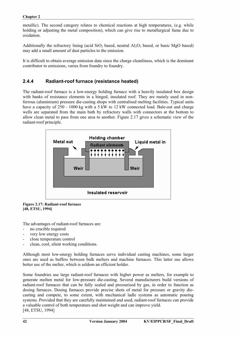
Chapter 2
42 Version January 2004 KV/EIPPCB/SF_Final_Draft
metallic). The second category relates to chemical reactions at high temperatures, (e.g. whileholding or adjusting the metal composition), which can give rise to metallurgical fume due tooxidation.
Additionally the refractory lining (acid SiO2 based, neutral Al2O3 based, or basic MgO based)may add a small amount of dust particles to the emission.
It is difficult to obtain average emission data since the charge cleanliness, which is the dominantcontributor to emissions, varies from foundry to foundry.
2.4.4 Radiant-roof furnace (resistance heated)
The radiant-roof furnace is a low-energy holding furnace with a heavily insulated box designwith banks of resistance elements in a hinged, insulated roof. They are mainly used in non-ferrous (aluminium) pressure die-casting shops with centralised melting facilities. Typical unitshave a capacity of 250 – 1000 kg with a 5 kW to 12 kW connected load. Bale-out and chargewells are separated from the main bath by refractory walls with connectors at the bottom toallow clean metal to pass from one area to another. Figure 2.17 gives a schematic view of theradiant-roof principle.
Figure 2.17: Radiant-roof furnace[48, ETSU, 1994]
The advantages of radiant-roof furnaces are:- no crucible required- very low energy costs- close temperature control- clean, cool, silent working conditions.
Although most low-energy holding furnaces serve individual casting machines, some largerones are used as buffers between bulk melters and machine furnaces. This latter use allowsbetter use of the melter, which is seldom an efficient holder.
Some foundries use large radiant-roof furnaces with higher power as melters, for example togenerate molten metal for low-pressure die-casting. Several manufacturers build versions ofradiant-roof furnaces that can be fully sealed and pressurised by gas, in order to function asdosing furnaces. Dosing furnaces provide precise shots of metal for pressure or gravity die-casting and compete, to some extent, with mechanical ladle systems as automatic pouringsystems. Provided that they are carefully maintained and used, radiant-roof furnaces can providea valuable control of both temperature and shot weight and can improve yield.[48, ETSU, 1994]

Chapter 2
KV/EIPPCB/SF_Final_Draft Version January 2004 43
2.4.5 Rotary furnace
2.4.5.1 Description
The rotary furnace consists of a horizontal cylindrical vessel, in which the metallic charge isheated by a burner located at one side of the furnace. The flue-gases leave the oven through theopposite side. To generate the required heat, fuel or natural gas is used combined with air orpure oxygen.
A tilting mechanism allows the furnace to be lifted to a certain angle or into a vertical position.This position is used for charging of the furnace with a drop bottom bucket or a vibrating chute,and for lining repair or renewal. During heating and melting the furnace is rotated slowly toallow the heat transfer and distribution. The furnace atmosphere is controlled by the air(oxygen)/fuel ratio.
Once the metal is melted, and after a composition check and adjustment, a tap-hole in front ofthe furnace is opened and the melt in the furnace is discharged into ladles. Because of its lowerdensity, the slag floats on the metal bath in the furnace and is finally collected through the tap-hole into slag pots.
A melting cycle spans 1½ to several hours. For continuous molten metal production, foundriesinstall 2 to 4 rotary furnaces, which are operated consecutively. The thermal efficiency of therotary furnace is very high, i.e. at 50 to 65 %3, depending on the capacity. This high yield isachieved by using pure oxygen instead of air as the combustion medium.[32, CAEF, 1997]
2.4.5.2 Melting practice
For cast iron melting, the furnace is charged with pig iron, foundry returns, steel scrap, slagging(e.g. sand, lime), and carburisation agents (e.g. graphite). The melting cycle starts with a slightlyoxidising and short flame (air factor, λ = 1.03), which gives the highest energy input. Thefurnace is rotated stepwise through 90 º and the direction of the rotation is changed from time totime. This way, the furnace walls can exchange heat with the charge by convection. As soon asthe charge is melted, the flame is reduced to prevent excessive oxidation of the alloyingelements. During overheating and holding, a long and reducing flame is applied (λ = 0.9) andthe furnace movement is changed to full and continuous rotation. The slag layer providesthermal insulation and prevents the burning-off of the alloying elements. After controlling andadjusting the melt composition and temperature, the tap-hole is opened and the metal is tappedinto ladles. The slag floats on the metal bath and is collected separately after the metal isremoved.
The lifespan of the refractory is largely dependent on the overheating temperature and thecharge composition. In the charging operation, mechanical shocks and cold start-ups need to beprevented. The furnace atmosphere, the holding time, rotational speed and the burner positionalso affect the refractory life. In normal conditions the refractory life is 100 to 300 meltingcycles.[32, CAEF, 1997], [110, Vito, 2001]
2.4.5.3 Metallurgy
The rotary furnace has been used in non-ferrous melting for many years. In this applicationtraditional oil-air burners can provide the relatively low melting temperatures. The developmentof oxygen-air burners has enabled the introduction of cast iron production, using a higherrelative amount of steel scrap and applying graphite for carburisation. 3 That is providing the energy for oxygen production is not taken into account. With oxygen production, the efficiency will be 10
to 15 % less.

Chapter 2
44 Version January 2004 KV/EIPPCB/SF_Final_Draft
A significant disadvantage of the rotary furnace is that it also burns Fe, C, Si, Mn and S. Theselosses have to be compensated for by the addition of alloying elements before or after melting.The efficiency of uptake of these elements is usually rather low. Concentration gradients mayoccur between the front and the back of the metal bath due to the absence of axial motion anddue to inhomogeneities in radiation and the atmosphere above the wide bath surface.[110, Vito, 2001]
2.4.5.4 Application
Due to its batch character, the rotary furnace provides an equal flexibility as the corelessinduction furnace in the cast iron foundry. The investment costs however are lower. A 5 tonnefurnace costs EUR 500000 – 600000, of which 30 % are for the exhaust system and dedusting.The rotary furnace is also a good alternative for the small-scale cold blast cupola, due to itshigher flexibility and lower environmental costs. Rotary furnaces are used for melting volumesof 2 to 20 tonnes, with production capacities of 1 to 6 tonnes per hour.[110, Vito, 2001]
2.4.5.5 Advantages:
- quick change of alloy possible- melting without contamination, e.g. without sulphur pick-up- low investment costs- small dedusting system because of low flue-gas rate- easy to maintain.
2.4.5.6 Disadvantages:
- easy burn-out of C, Si, Mn- gas and oxygen use can be high if not operated continuously- the energy consumption increases if more steel is added to the charge.[110, Vito, 2001]
2.4.6 Hearth type furnace
The hearth type furnace is also known as a reverberatory or bale-out furnace. It is a staticfurnace with direct heating. Hot air and combustion gases from oil or gas burners are blownover the metal (melt) and exhausted out of the furnace. The hearth type furnace finds its mainapplication in non-ferrous metal melting. A typical furnace design is given in Figure 2.18.
Figure 2.18: Cross-section of a hearth type furnace[175, Brown, 1999]

Chapter 2
KV/EIPPCB/SF_Final_Draft Version January 2004 45
This is a refractory lined, rectangular or circular bath furnace that is fired by wall or roof-mounted burners. Varieties of fuels are used and additionally oxy-fuel burners can be used toincrease the melting rate. Extraction and treatment of the combustion gases is typically carriedout and for this the furnaces are partially sealed. Hoods and covered launders provide extractionduring tapping and charging. The furnace can be constructed in a number of configurationsdepending on the particular metal and application, variations include the provision of slopinghearths and side wells for specific melting purposes, tuyères and lances for the addition ofgases. The furnaces can sometimes be tilted to pour or blow metal.
The melting efficiency of a hearth type furnace is usually not great because of the poor heattransfer from the burner. The efficiency has been improved in practice by the use of oxygenenrichment or by using combinations of gas and solid fuel to extend the flame length. Thesefurnaces are used for batch melting, refining and for holding a variety of metals. Hearth typefurnaces are mainly used to melt large quantities of non-ferrous metals [155, European IPPCBureau, 2001].
Large hearth type furnaces give rapid melting and can handle bulky charge materials, but thedirect contact between the flame and charge may lead to high metal losses, gas pick-up and toconsiderable oxide contamination. Temperature control can also be difficult. These difficultiescan be overcome to some extent by good practice. For example, dross can be removed byapplying suitable fluxing practice, and applying modern burners reduces problems with thetemperature control. After tapping, filtering and degassing, further treatments can be applied asthe metal is transferred to holding furnaces.[42, US EPA, 1998], [48, ETSU, 1994], [155, European IPPC Bureau, 2001], [175, Brown,1999]
2.4.7 Shaft furnace
2.4.7.1 Description
This is a simple vertical furnace with a collecting hearth (inside or outside the furnace) andburner system at the lower end and a material charging system at the top. The burners areusually gas-fired. Metal is fed into the top of the furnace and is melted as it passes down theshaft. Independent control of the fuel/air ratio is usually provided for each burner. ContinuousCO or hydrogen monitoring is also provided for each row of burners and monitor thecombustion gases from each burner in turn. Combustion gases are usually extracted andcleaned. An afterburner is sometimes used to decompose any carbon monoxide, oil, VOCs ordioxins that are produced. The addition of oxygen above the melting zone has been used toprovide afterburning in the upper levels of shaft or blast furnaces.
The furnace is used to melt pure metal, but occasionally metal that is contaminated with organicmaterial may be used. If oily metal is fed into the furnace, it passes through a temperaturegradient existing between the charging area and the burners. The low temperature can produce amist of partially burned organic material. The shaft furnace is also used to preheat the chargematerial before smelting. A typical representation of this furnace is given in Figure 2.19.
This furnace type is only used for non-ferrous metal melting, mainly for aluminium. Due to thecomplex construction and difficult renewal of the refractory, the furnace is only used for metalswith low melting points. Therefore, the maintenance requirements of the furnace lining arerather limited. Typical refractory lifetimes are 4 to 8 years.
Modern furnace types with computer controlled burner systems reach an energy use of650 kWh/tonne of melted Al. (at 720 ºC). The theoretical energy needed is 320 kWh/tonne. Thethermal efficiency therefore is 50 %.

Chapter 2
46 Version January 2004 KV/EIPPCB/SF_Final_Draft
The shaft furnace is a continuous melting furnace with high capacity, ranging from 0.5 to5 tonnes per hour and with a holding capacity of up to 50 tonnes. Due to its holding function, achange of alloy is difficult.[48, ETSU, 1994], [155, European IPPC Bureau, 2001]
Figure 2.19: Shaft furnace[48, ETSU, 1994]
2.4.7.2 Advantages:
- due to the long preheating, the charge is very well dried before the melting starts. Thismakes the furnace well suited for Al, due to the reduced risk of hydrogen uptake
- relatively low investment and operating costs. Operating costs are kept low by the effectivepreheating, automatic control and long refractory life
- technical advantages are: low gas pick-up, excellent temperature control and low metal loss.
2.4.7.3 Disadvantages:
- no flexibility regarding a possible change of alloy.[110, Vito, 2001]
2.4.8 Crucible furnace
2.4.8.1 Description
These are simple crucibles that are heated externally by the combustion gases from gas or oilcombustion, by electricity or, for lower temperatures, by thermal fluid. Contact with a directflame is avoided to prevent there being local hot spots at the base of the crucible and so thatgood temperature control can be maintained in the melt, to prevent oxidation and vaporisationof the metal.

Chapter 2
KV/EIPPCB/SF_Final_Draft Version January 2004 47
This furnace type is only used for non-ferrous metal melting. Due to the indirect heating(through the crucible wall) no burn-off or gas take-up can take place. These furnaces are usedfor the production of small amounts of molten metal (less than 500 kg per batch) and for lowproduction capacities. Example furnaces are displayed in Figure 2.20.
Figure 2.20: Crucible furnaces[237, HUT, 2003]
The crucible is tilted manually, with a crane, or automatically to pour the molten metal into themould. For copper based materials, only graphite or carborundum (silicon carbide) crucibles areused, whereas aluminium can also be melted in cast iron crucibles.
Crucibles used for holding, transport and metal treatment in ferrous foundries are called ladles.[110, Vito, 2001], [126, Teknologisk, 2000], [225, TWG, 2003]
2.4.8.2 Melting practice
The cold load is brought into the crucible, and heating is started at full power in order to meltthe load. At 50 to 100 ºC below the melting temperature, the power is switched off, and the loadis heated further by the thermal inertia of the crucible. Afterwards, the temperature is levelledoff using a control system. After deslagging, metal treatment can be performed. This involvesoxygen removal, degassing, grain refining and the adjustment of volatile metals such as zincand magnesium. The slag is then removed once more before casting takes place.
Besides regular renewal of the crucible, no maintenance is needed. The renewal time isprimarily dependent on the alloy to be melted. Multiple alloy changes cause a more rapidcrucible wear. SiC-crucibles, used for low melting alloys, have a useful life of 130 to 150charges. For high melting alloys, the useful life is 50 to 80 charges.
Thermal efficiencies are 750 – 3000 kWh per tonne of aluminium, i.e. 15 - 30 % efficiency.[34, Binninger, 1994], [110, Vito, 2001], [126, Teknologisk, 2000]
2.4.8.3 Advantages:
- simple technology- low maintenance- flexibility regarding change of alloy.
2.4.8.4 Disadvantages:
- low efficiency and production capacity.[110, Vito, 2001]
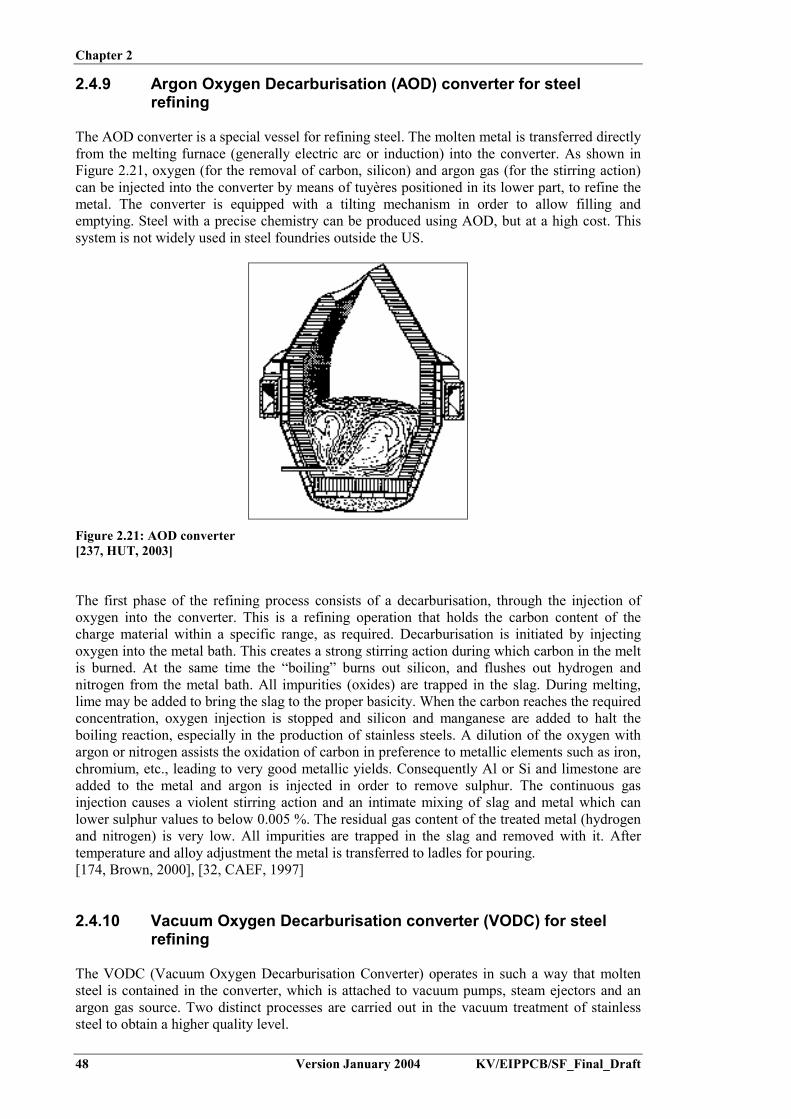
Chapter 2
48 Version January 2004 KV/EIPPCB/SF_Final_Draft
2.4.9 Argon Oxygen Decarburisation (AOD) converter for steelrefining
The AOD converter is a special vessel for refining steel. The molten metal is transferred directlyfrom the melting furnace (generally electric arc or induction) into the converter. As shown inFigure 2.21, oxygen (for the removal of carbon, silicon) and argon gas (for the stirring action)can be injected into the converter by means of tuyères positioned in its lower part, to refine themetal. The converter is equipped with a tilting mechanism in order to allow filling andemptying. Steel with a precise chemistry can be produced using AOD, but at a high cost. Thissystem is not widely used in steel foundries outside the US.
Figure 2.21: AOD converter[237, HUT, 2003]
The first phase of the refining process consists of a decarburisation, through the injection ofoxygen into the converter. This is a refining operation that holds the carbon content of thecharge material within a specific range, as required. Decarburisation is initiated by injectingoxygen into the metal bath. This creates a strong stirring action during which carbon in the meltis burned. At the same time the “boiling” burns out silicon, and flushes out hydrogen andnitrogen from the metal bath. All impurities (oxides) are trapped in the slag. During melting,lime may be added to bring the slag to the proper basicity. When the carbon reaches the requiredconcentration, oxygen injection is stopped and silicon and manganese are added to halt theboiling reaction, especially in the production of stainless steels. A dilution of the oxygen withargon or nitrogen assists the oxidation of carbon in preference to metallic elements such as iron,chromium, etc., leading to very good metallic yields. Consequently Al or Si and limestone areadded to the metal and argon is injected in order to remove sulphur. The continuous gasinjection causes a violent stirring action and an intimate mixing of slag and metal which canlower sulphur values to below 0.005 %. The residual gas content of the treated metal (hydrogenand nitrogen) is very low. All impurities are trapped in the slag and removed with it. Aftertemperature and alloy adjustment the metal is transferred to ladles for pouring.[174, Brown, 2000], [32, CAEF, 1997]
2.4.10 Vacuum Oxygen Decarburisation converter (VODC) for steelrefining
The VODC (Vacuum Oxygen Decarburisation Converter) operates in such a way that moltensteel is contained in the converter, which is attached to vacuum pumps, steam ejectors and anargon gas source. Two distinct processes are carried out in the vacuum treatment of stainlesssteel to obtain a higher quality level.

Chapter 2
KV/EIPPCB/SF_Final_Draft Version January 2004 49
First, the steel is decarburised by introducing oxygen into the melt. At the same time, someargon is injected from the converter base. The converter uses vacuum pumps to lower the partialpressure of carbon monoxide, to such an extent that effective decarburisation can be carried outwithout oxidising too much of the chromium. This first process is similar to AODdecarburisation, but less argon is needed thanks to the lower total gas pressure and the process ismuch more efficient. The oxidised chromium is reduced back to liquid steel with aluminium.
The second process involves degassing. The converter is brought under deep vacuum(1 - 5 mbar) using a water ring pump and steam ejectors. Slight argon bubbling is continued inorder to maintain an effective steel movement. At the very low pressure, gaseous impuritiessuch as hydrogen and nitrogen are eliminated effectively. At the same time, the total oxygencontent and the sulphur content are drastically decreased, which is beneficial for the mechanicalproperties of the end steel.
Low alloyed steels are normally only degassed.
The VODC process provides specific steel qualities, which cannot be obtained by othermethods. The total oxygen content is also lower than what is typical for electric arc melted andAOD-treated steel, because a high level of oxide inclusions are removed form the melt duringthe VODC process, and most of the dissolved oxygen is further removed during the degassingphase.[202, TWG, 2002]
2.4.11 Metal treatment of steel
In order to guarantee a good casting quality, cast steel needs further treatment to removeimpurities and the possible causes of defects, i.e.:
- Deoxidation: Oxygen dissolves in liquid steel, in the form of FeO. During solidification, theoxygen can then combine with C in the steel to form CO. This process can thus change thecomposition of the steel and generate porosity. Deoxidation is therefore always necessary.Deoxidation is performed with an element that preferentially binds the oxygen. Silicon,calcium silicide, titanium, zirconium and aluminium are possible deoxidants, withaluminium being the most powerful and the one that is most generally used. Aluminium isadded in the form of a stick or wire (see Figure 2.22). The treatment is usually performed inthe furnace and in the ladle. The produced aluminium oxide is insoluble in the melt andmixes with the slag.
Figure 2.22: Deoxidation, using an aluminium wire[237, HUT, 2003]

Chapter 2
50 Version January 2004 KV/EIPPCB/SF_Final_Draft
- Sulphide formation: As the tensile strength of steel increases, the harmful effect of sulphurincreases. Sulphur is soluble in liquid steel, but on solidification it precipitates as MnS.Precipitates can take various forms and have different effects. The form of the sulphides isrelated to the residual aluminium content after deoxidation. The residual amount of Alshould allow the formation of type III sulphides.
[110, Vito, 2001], [174, Brown, 2000]
2.4.12 Cast iron treatment
2.4.12.1 Alloying
During melting, some elements in the melt oxidise and are lost to the slag. At the end of themelting period a correction of the composition needs to be performed, in order to guarantee theappropriate final quality. For unalloyed cast iron, this is needed for: C, Si, Mn, S and P. Ifspecial properties are desired, specific alloying elements can be added, ranging from aluminiumto zirconium, in concentrations of less than 1 % to more than 30 %. In general these are addedas ferrous alloy blocks or grains. The additions are made to the liquid iron, since this reduces therisk of oxidation losses.
The addition is performed in the furnace, in the molten metal flow during pouring, or by puttingthe additives in the transport ladle before pouring the molten metal into it.[110, Vito, 2001]
2.4.12.2 Homogenisation
The addition of alloying elements can introduce impurities such as oxides, sulphides or carbidesinto the iron. In order to reduce the negative effects from these compounds, the metal isoverheated at 1480 ºC to 1500 ºC. Nevertheless overheating can affect graphite precipitationduring solidification. Homogenisation has the following positive effects:
- reduction of oxides (FeO, SiO2, MnO) by C, generating CO-bubbles. On their way throughthe melt these bubbles remove H2 and N2 from the melt
- at high temperature and under intense bath movements, impurities coagulate and rise to themelt surface more quickly, where they are then taken up by the slag.
[110, Vito, 2001]
2.4.12.3 Desulphurisation and recarburisation of cupola melted iron
Due to the intimate contact of the liquid metal with the coke, cupola melted iron shows arelatively high sulphur content. Sulphur pick-up in the cupola gives rise to a lower viscosity ofthe liquid metal, which is an advantage in some cases, e.g. for thin walled grey iron castings.
However, if the cast iron is to be treated with Mg (as described in the next section) to produce anodular cast iron quality then the sulphur should be neutralised, to prevent excessive Mgconsumption. This is performed by using one of a number of methods. In the porous plugmethod, nitrogen or argon gas is used to agitate the metal and CaC2 powder is added to themetal. Upon contact with the liquid metal CaS is formed and removed as slag. The treated metalthen flows to a holding ladle from which it is tapped for further treatment.

Chapter 2
KV/EIPPCB/SF_Final_Draft Version January 2004 51
2.4.12.4 Nodularisation treatment of the melt
Nodular cast iron is obtained by the addition of Mg, either pure or as a FeSiMg or NiMg alloy,to the molten metal. Prior to this, a desulphurisation treatment may be necessary to guaranteesuccessful nodularisation. The presence of Mg in the melt provokes a solidification of thegraphite phase in the shape of microscopic spheres. This gives rise to higher mechanicalproperties, such as strength and ductility.
There are several techniques that can be applied to introduce Mg into the liquid metal:- The pour over technique: This is the simplest method, whereby the liquid metal is poured
over the Mg alloy in the bottom of the ladle- The sandwich method: Here Mg alloy is placed at the bottom of a specially designed ladle
and covered with steel sheets or FeSi, as shown in Figure 2.23. The metal is poured into theladle and after melting of the cover the Mg reaction takes place
- The Tundish Cover: This is an improved sandwich technique, whereby the ladle is coveredby a lid after the Mg alloy has been placed at the bottom of the ladle. The metal is poured inthe concave lid and flows through a hole in the ladle, where the reaction takes place
- The plunging method: Using a plunger bell, the Mg alloy is submerged in the liquid metaluntil the reaction is finished. During the treatment the ladle lid is closed, to prevent MgOfume emissions
- The G Fischer converter: This process uses a special ladle that is closed tightly with a lidafter the metal is poured into the converter in the horizontal position. The converter is thentilted into a vertical position, allowing the Mg alloy to react with the metal. Once thereaction is finished the converter is turned back into the horizontal position and is tappedafter opening the lid
- The core wire injection: Here very fine powdered Mg alloy is rolled in tin steel sheet,forming a filled wire. This wire is then injected, by a controlled mechanism, into a slendershaped ladle, where the Mg is released
- The flow through treatment: Here the metal is poured into a special designed reactionchamber in which the Mg alloy was put earlier
- The ductilator: In this method the metal is poured into a reaction chamber where the flow isforced to form a vortex. The Mg alloy is injected into the vortex with an inert carrier gas.The treatment can be performed on large quantities of metal or during mould filling
- The inmold process: In this process the Mg alloy, shaped as a tablet, is put directly into themould cavity (gating system). The reaction takes place during mould filling, ensuring a highyield.
Figure 2.23: The sandwich method for nodularisation[237, HUT, 2003]
After treatment, the metal has to be poured into the mould within a specific time, as the Mgeffect tends to fade quickly, necessitating a new treatment if a certain time limit (10 to 15 min)is exceeded.

Chapter 2
52 Version January 2004 KV/EIPPCB/SF_Final_Draft
2.4.12.5 Inoculation of the melt
The presence of coarse shaped graphite in a metal matrix leads to poor mechanical properties ofthe material. In order to get a fine crystalline metallurgical structure, inoculation of the melt isnecessary prior to casting. This process introduces seeds for crystal growth into the metal melt.Usually FeSi alloys are used for this purpose. Ca, Al and rare earth materials are often includedin the inoculant.
Again, several techniques can be used to inoculate the molten metal:- Injection during tapping: Here the inoculant is injected directly into the metal flow during
tapping- Injection during pouring: Here the inoculant is injected directly into the metal flow during
pouring of the mould (see Figure 2.24)- Filled wire injection in the melt (see Section 2.4.12.4)- Inmold process (see Section 2.4.12.4).
Figure 2.24: Inoculation during pouring[237, HUT, 2003]
2.4.13 Non-ferrous metal treatment
There are three main metal treatment (or refining) operations carried out in aluminium meltingprocesses. These are as follows:
- Degassing: Molten aluminium dissolves hydrogen, which is then expelled upon cooling andcan thus lead to porosity in the finished casting. Hydrogen therefore needs to be removed.This is done by bubbling an inert gas through the melt. Good degassing methods providebubbles with high residence time and high surface area. The degassing of aluminium ismostly performed using an impeller station. This treatment uses a rapid-spinning mixer andnitrogen injection into the melt. Degassing is often combined with a cleaning of the melt.Cleaning is performed to remove alkali or alkaline earth metals, such as Ca. Cleaning can bedone by Cl2-gas. The use of HCE for this purpose has been banned in the EU (Dir.97/16/EC). A mixture of nitrogen with 3 % Cl2 is generally used, for simultaneousdegassing and cleaning. Alternative degassing methods use tablets, a lance with a poroushead, or a porous stone in the holding furnace
- Modification and grain refining: For aluminium alloys this usually involves the addition ofsmall amounts of metal to the melt. These additions control the grain size and modify themicrostructure of the solidifying metal and thus enhance the casting mechanical properties.Sodium or strontium are used for the modification, while grain refinement is achieved withtitanium, titanium boride, zircon or carbon. This treatment is mostly performed incombination with degassing in a dedicated metal treatment station
- Fluxing: This usually involves the addition of solid fluoride based fluxes to the melt, toremove solid contaminants.
[164, UK Environment Agency, 2002], [175, Brown, 1999], [178, Wenk, 1995]

Chapter 2
KV/EIPPCB/SF_Final_Draft Version January 2004 53
There are four main metal treatment (or refining) operations carried out in magnesium meltingprocesses. These are as follows:- Grain modification: Grain modifiers for magnesium alloy processes are usually in the form
of zirconium or formerly hexachloroethane. The use of HCE for this purpose has beenbanned in the EU (Dir. 97/16/EC)
- Fluxing: This usually involves the addition of alkali, earth alkali, chloride and fluorideproprietary fluxes to the melt to remove solid contaminants
- Degassing: For magnesium processes, nitrogen or argon gas sparging may take place fordegassing and oxide removal. The degassing of magnesium alloys may also be effected by amixture of argon and chlorine gases, when argon is used as a carrier gas
- Oxidation control: The presence of beryllium within the melt grain modifies and stopsoxidation. Finished magnesium alloys may contain up to 15 ppm beryllium by weight. Amaster alloy of aluminium/beryllium, containing up to a nominal 5 % beryllium, may beadded to the molten magnesium alloy to give it this beryllium loading. Oxidation controlmay also be achieved by blanketing the surface of the metal with a carrier gas, such ascarbon dioxide or argon, containing up to 4 % sulphur hexafluoride. To date, the only flux-free alternative to SF6 is SO2. SO2 is significantly cheaper then SF6 but its main drawback isits toxicity, and as a result operations need to be enclosed better. Up to the present, only 1/3of the foundries in Europe have been using SO2. Occasionally oxidation control may beachieved by sprinkling sulphur powder on the surface of the melt. This issue is discussed inSection 4.2.7.1.
There are three main metal treatment (or refining) operations carried out in copper meltingprocesses. Molten copper dissolves oxygen and hydrogen, which may recombine to form watervapour. This in turn will generate porosity in the casting. Degassing and deoxidation are thusapplied to remove hydrogen and oxygen, respectively. The applicable metal treatmentoperations are as follows:
- Deoxidation: Deoxidation is performed by adding a reagent which binds the oxygen andforms a fluid slag. Care must be taken to prevent the deoxidation products from beingentrained in the solidified casting and the residual deoxidant from adversely affecting thealloy properties. Phosphorus is the most commonly used deoxidation reagent. Alternativesare magnesium, manganese, calcium, silicon and boron
- Degassing: Hydrogen is removed from the melt by bubbling an inert gas through it. Bothargon and nitrogen may be used. The technique is comparable to aluminium degassing
- Fluxing: Aluminium in alloys can oxidise and generate oxide skins. These can causeproblems upon casting. In non-aluminium alloys, traces of aluminium can cause defects.Therefore they need to be removed, using fluxing agents. Fluxes are also used to cover thesurface in order to prevent oxidation, zinc loss and hydrogen pick-up during melting.Specific fluxing agents exist for each type of treatment.
[165, UK Environment Agency, 2002], [182, Closset, 2002]
2.5 Mould and core production
Moulding consists of making a mould in which the molten metal will be poured. Some mouldsmay need to have special properties to produce high quality castings, which, for example:
- reproduce exactly and with a high dimensional precision the shape of the casting model- give a smooth skin to the casting in order to avoid excessive fettling- avoid any casting defects such as cracks, worming, pinholes, etc.
Just as the mould defines the outer shape of the casting, the core defines the inner one, or atleast the parts not directly attainable by moulding.

Chapter 2
54 Version January 2004 KV/EIPPCB/SF_Final_Draft
Moulds may be classified in two large families:
- lost moulds (single use moulds): These are specially made for each casting and aredestroyed after pouring. The moulds are generally made of sand, and are chemically-bonded, clay-bonded, or even unbonded. Investment casting can also be included in thisfamily
- permanent moulds (multi use moulds): These are used for gravity and low-pressurecasting, pressure die-casting, and centrifugal casting. Typically the moulds are metallic.
The cores used for ferrous castings are practically always made of sand. The choice of bindertechnology used depends on factors such as the size of the casting, the production rate, the metalpoured, the shake-out properties, etc.
For sand moulding, the mould may be produced by manual or mechanical ramming actions,such as by jolt, squeeze, air impact, vibration, etc.. When the mould has sufficient strength it isreleased from the model, which can then be used to produce a new mould.
Generally, cores are produced by the same techniques as moulds, but small or medium sizedcores are often blown or shot into wooden, plastic or metallic core-boxes.
For non-ferrous casting, about 30 % of copper alloys are cast in sand moulds. Only about 10 %of light non-ferrous metals are cast in single use moulds.
The production of patterns and dies is generally carried out by specialised external suppliers.These activities are found in the metal and plastics treatment sectors.[2, Hoffmeister, et al., 1997], [32, CAEF, 1997], [110, Vito, 2001]
2.5.1 Raw materials
2.5.1.1 Refractory materials
Whatever binder applied, the physical and chemical properties of the refractory material used tomake the moulds or cores affects their characteristics and their behaviour during pouring. Thisis not surprising as these materials make up 95 to 99 % of the products used.
The purchase price of each sand type has four main components – extraction, preparation,packaging and transportation. Transportation costs will vary for different regions. The mainfactor however in the price is the sand type. The average purchase price for the various typesvaries widely. From a 1995 UK questionnaire, the tonnage price of chromite and zircon sandwere respectively a factor 9 and 14 times higher than that of silica sand. In Portugal the cost ofsand varies according to the amount purchased, but sand is generally cheaper in Portugal than inSpain, France or Italy. Portuguese prices (year 2003) range between EUR 20 - 25 per tonne ofdry sand AFS 55, plus transport. Prices in the Czech Republic (year 2003) for silica sand rangebetween EUR 10 and 20 for silica sand, with the price depending on the volume, packaging andtreatment of the sand. The price for chromite sand is EUR 250 – 300/t, and for zircon sandEUR 250 – 400/t.[72, ETSU, 1995], [225, TWG, 2003]
The different types of refractory sands used for foundry purposes are described in the followingsections.

Chapter 2
KV/EIPPCB/SF_Final_Draft Version January 2004 55
2.5.1.1.1 Silica sand
This type of sand is the most commonly used, mostly because of its wide availability and itsrelatively low cost. Silica sand is composed of the mineral "quartz" (SiO2), which is more orless pure and clean, depending on its origin. Its dry piece specific weight fluctuates between 2.5to 2.8 kg/dm³. The dry bulk density (or loose volume weight) of silica sand is 1.4 to 1.6 kg/dm³.
The thermal expansion of silica sand generates a mould movement upon pouring and cooling.Specific additives are therefore used, especially when producing cores, in order to preventcasting errors. These may be wood fluff, iron oxide or cured foundry sand. Sand containingfeldspar has a lower thermal expansion than pure quartz sand and a lower sintering point, but itis widely used in order to minimise expansion defects in castings.
Silica sand is neutral and is compatible with all binders and normal cast alloys. The respirableparticulate matter (RPM) fraction of quartz is classified by IARC as carcinogenic [233, IARC,1997]. This is a health and safety issue. Studies are ongoing to determine whether or not an airpollution issue also exists. The amount of quartz in dust is defined by the content of quartz inthe input materials.
In green sand moulding technology, control of the grain size distribution is very important.Figure 2.25 shows a typical grain size distribution for silica sand. The grain size distribution isused to calculate the AFS-number (AFS = American Foundry Society). This gives the overallfineness of the sand. The higher the AFS-number, the finer the sand. An alternativeclassification system is the middle grain number or MK.
A finer sand grade will have more grains per gram, and thus a higher surface area. This requiresmore binder addition for an equal mould strength. Operators therefore try to use the coarsestsand, but one that still gives a good surface finishing aspect. Standard AFS-numbers are 50 – 60. For very smooth surfaces a fine sand is needed, typically one with an AFS of 90 – 110 isused. Fine sands are also used in some instances to replace mould coatings.[110, Vito, 2001], [202, TWG, 2002], [225, TWG, 2003]
0.53 1.32
7.79
39.70 37.78
11.49
0.99 0.00 0.00 0.000.400
20
40
60
80
100
0 63 90 125 180 250 355 500 710 1000 1400
Mesh width (µm)
Siev
e re
sidu
e (%
)
Figure 2.25: Typical grain size distribution for silica foundry sand[110, Vito, 2001]

Chapter 2
56 Version January 2004 KV/EIPPCB/SF_Final_Draft
2.5.1.1.2 Chromite sand
Chromite is a chrome ore, with the theoretical formula FeO.Cr2O3, which contains othercomponents such as magnesium and aluminium oxides. For its use in foundries, its silicacontent must be lower than 2 % in order to prevent sintering at low temperatures. Itscharacteristics are as follows:
- density: 4.3 to 4.6, cf. 2.65 for silica sand- theoretical melting point: 2180 ºC, but the presence of impurities can lower this to 1800 ºC- thermal diffusivity: more than 25 % higher than that of silica sand- thermal expansion: regular, without a transition point, and lower than that of silica sand- pH: rather basic, from 7 to 10.
Chromite sand is more refractory than silica. It is more thermally stable and has a greaterchilling power. Chromite sand provides a better surface finish on large castings. It is thereforeused for the production of large castings and in areas of the mould where chilling is required.[32, CAEF, 1997]
2.5.1.1.3 Zircon sand
Zircon is a zirconium silicate, ZrSiO4. Zircon is the most widespread zirconium ore. Itscharacteristics are as follows.
- density: 4.4 to 4.7, cf. 2.65 for silica sand- melting point: higher than 2000 ºC- thermal diffusivity: more than 30 % higher than that of silica sand- thermal expansion: regular, without a transition point, and lower than that of silica sand.
The general characteristics of zircon sand are similar to that of chromite, but zircon sandproduces a better finish as a finer grade is used. These physical and thermal properties accountfor its use for moulding or core-making in difficult cases, in spite of its very high price.[32, CAEF, 1997], [72, ETSU, 1995]
2.5.1.1.4 Olivine sand
Olivine sands are a mineral group which includes forsterite, fayalite and others. Thecharacteristics of olivine sands are as follows:
- melting point: forsterite: 1890 ºC, fayalite: 1205 ºC- density: 3.2 to 3.6- pH: around 9.
The basic pH makes this type of sand not suitable for use with acid catalysed binder systems.
Olivine sand is produced by crushing natural rocks, which explains its diverse characteristics. Itis usually used for moulding and core-making in manganese steel casting. The presence ofmanganese prohibits the presence of silica as these two components react to give a very fusiblecompound. The reported purchase price in Spain is EUR 130/tonne (2002).[32, CAEF, 1997], [210, Martínez de Morentin Ronda, 2002]

Chapter 2
KV/EIPPCB/SF_Final_Draft Version January 2004 57
2.5.1.2 Binders and other chemicals
2.5.1.2.1 Bentonite
Bentonite is a smectite clay, which has a lamellar structure. By adding water, the clay structureswells due to the adsorption of water molecules. The clay then becomes workable and can bespread to coat the sand grains during mixing.
Natural calcium bentonites do not swell or gel when mixed with water. They are rarely used atpresent, being used only for very special castings. Alternatively, these materials may be"activated" by treatment with soda ash to give "soda activated bentonites". These are usedextensively in ferrous foundries throughout Europe; their properties approach those of naturalsodium bentonites.
Natural sodium bentonites greatly swell when mixed with water. The main features in greensand are their high dry strength, good tolerance to water content variation, high resistance toburn-out and their improved high temperature durability. As they are imported from the US,where they are in common use, their price generally limits their use to high value steel castingor in blends with activated calcium bentonites.
Pouring molten metal into a green sand mould subjects the moulding-sand to considerable heat.This heat removes moisture from the sand and destroys the clay-bonded structure (andadditives). If during pouring and cooling bentonite stays below the deactivation temperature, thelamellar structure is maintained as well its ability to swell and develop cohesion. Thedeactivition temperature varies with the bentonite type.
Prices for bentonite range between EUR 70 – 250/t, depending on the packaging and producttype (Czech Republic, 2003).[32, CAEF, 1997], [73, ETSU, 1995], [202, TWG, 2002], [225, TWG, 2003]
2.5.1.2.2 Resins
Over the past few decades a range of chemical binders have been developed. These are single-or multi-component systems which are mixed with the foundry sand until all the grains arecoated with a thin film. After mixing, a hardening reaction starts, binding the sand grainstogether and developing mould strength. Resins can be classified according to the hardeningmethod:
- cold-setting resins- gas-hardened resins- hot-curing resins.
The various resin types will be discussed under Section 2.5.6. In Table 2.7 a survey of theapplicability of the various resins is given.

Chapter 2
58 Version January 2004 KV/EIPPCB/SF_Final_Draft
Hardening Resin type("commercial
name")
Mouldproduction
Coreproduction
Curingtemperature
Hardeningtime (*)
Metaltypes
Size ofseries
Cold-setting Furan Medium tolarge
Some 10 – 30 ºC 10 – 120min
Ferrous +non-
ferrous
Small tolarge
Phenolic Large No 10 – 30 ºC 10 – 180min
Ferrous Small tolarge
Polyurethane(“Pepset/Pentex")
Small tomedium
Some 10 – 30 ºC 5 – 60 min Ferrous +non-
ferrous
Small tolarge
Resol - ester("Alfaset")
Small toLarge
Some 10 – 30 ºC 5 – 400min
Ferrous +non-
ferrous
Small tolarge
Alkyd oil Large Some 10 – 30 ºC 50 min steel SmallSilicate -
Water glassMedium to
largeNo 10 – 30 ºC 1 – 60 min Ferrous +
non-ferrous
Small tomedium
Gas-hardening Phenolic/Furan1
("Hardox")Small Yes 10 – 30 ºC <60 s Ferrous +
non-ferrous
All
Polyurethane("Cold-box")
Small Yes 10 – 30 ºC <60 s Ferrous +non-
ferrous
All
Resol("Betaset")
Small Yes 10 – 30 ºC <60 s Ferrous +non-
ferrous
All
Acryl/Epoxy("Isoset")
No Yes 10 – 30 ºC <60 s Ferrous +non-
ferrous
All
Silicate Small Yes 10 – 30 ºC <60 s Ferrous +non-
ferrous
All
Thermosetting Oil Small Yes 180 – 240 ºC 10 – 60min
Ferrous Small
"Warm-box" Seldom Yes 150 – 220 ºC 20 – 60 s Ferrous Mediumto large
"Hot-box" Seldom Yes 220 – 250 ºC 20 – 60 s Ferrous +non-
ferrous
Mediumto large
"Croning" Yes Yes 250 – 270 ºC 120 – 180 s Ferrous +non-
ferrous
Large
(*) i.e. the release time - the time in which the mould/core has gained sufficient strength to be released from the pattern1 Not applied for capacities <20 tonnes/day
Table 2.7: Survey of various resin types and their applicability[110, Vito, 2001]
2.5.1.2.3 Coal dust
Coal dust is usually added to green sand for cast iron moulding. It is used to a limited extent insome non-ferrous foundries. Coal dust may be mixed with small amounts of resins and oilproducts. During casting, the thermal degradation produces ‘lustrous carbon’, which improvesthe casting surface finish and shake-out properties. Coal dust is added for three reasons:- to create an inert atmosphere in the mould cavity during pouring, through the combustion of
organic compounds, which in turn slows down the oxidation of metal (slag formation)- to reduce the penetration of metal in-between the quartz grains, through deposition of a
graphite film, which also creates a flat casting surface- to reduce the amount of sand remaining on the casting surface upon shake-out.
Chapter 2
KV/EIPPCB/SF_Final_Draft Version January 2004 59
In addition to the black and sticky dust caused by handling, coal dust may contain or generatepolycyclic aromatic hydrocarbons (PAH) during pouring.
For steel castings, coal dust is not used because of carbon pick-up. In this case, it is usuallyreplaced by cereal binders such as starch or dextrin.
Various types of coal dust replacements exist. These consist of blends of high volatile, highlustrous carbon materials blended with clays. They are generally more environmentallyacceptable than coal dust, i.e. producing less fume during casting, although some coal dustreplacements will generate more PAH in the sand.[174, Brown, 2000], [225, TWG, 2003]
2.5.1.2.4 Cereal binders
Cereal binders are used mainly in steel foundries to increase the strength and toughness of thegreen sand. There are two main types of cereal binder: starch and dextrin. Starch is the basicmaterial and is produced from a number of plant materials, with maize starch being the mostcommonly used for foundry purposes. Dextrin is a repolymerised form of starch, producedthrough a subsequent acid and thermal treatment of starch.
Starches can help to reduce expansion defects, since as they burn out, they allow the sand grainsto deform without deforming the mould. Cereals increase the green strength, dry strength andtoughness but can reduce the flowability. Dextrines improve the flowability and moistureretention, preventing moulds from drying out and edges becoming friable.
Cereal additions do not improve the erosion resistance of the sand nor its resistance to metalpenetration.[174, Brown, 2000], [175, Brown, 1999]
2.5.1.2.5 Iron oxide
Iron oxide reacts with quartz at high temperature and forms a low melting compound, fayalite.This glassy plastic product sinters the grains together. It is mainly used in the production of coresand, in order to reduce the formation of veins.[110, Vito, 2001]
2.5.1.3 Running, gating, feeding and filtration
The different parts of the running and gating system are shown in Figure 2.26. The systemcarries out the following functions:
- controls the flow of the metal into the mould cavity at the rate needed to avoid cold metaldefects in the casting
- avoids turbulence of metal entering the mould- prevents slag and dross present in the melt from entering into the mould- avoids high velocity impingement of the metal stream onto cores or mould surfaces- encourages thermal gradients within the casting, which help to produce sound castings- enables the casting to be separated from the running/gating system easily.

Chapter 2
60 Version January 2004 KV/EIPPCB/SF_Final_Draft
Figure 2.26: Components of the running and gating system[237, HUT, 2003]
The design of the running system needs to take account of the varying slag and dross formingproperties of the metal to be poured, e.g.:- in lamellar iron, some furnace slag may be present but the melt is not subject to inclusions
due to oxidation- nodular iron contains magnesium silicate and sulphide dross, arising from the nodularisation
treatment- steel is susceptible to oxidation and slag formation- aluminium alloys (and aluminium bronzes) are all subject to dross formation, whereby a
film of oxide forms immediately on any metal surface exposed to air.
Inclusions in steel can arise from slag entrapment, the erosion of furnace or ladle linings orrefractories, or from deoxidation. Filtration is now widely used to reduce the presence ofinclusions. The introduction of ceramic filters has even enabled simplifications to be made inthe design of running and gating systems. Various types of filters are shown in Figure 2.27.
Figure 2.27: Various types of filters[237, HUT, 2003]
2.5.2 Sand preparation (transport, sieving, cooling, mixing)
2.5.2.1 Sand conditioning for green sand moulding
One of the major advantages in using green sand moulding is that the sand from the moulds canbe reconditioned for multiple re-use. The layout of a typical green sand plant is depicted inFigure 2.28, and some examples of sand mixers are shown in Figure 2.29.

Chapter 2
KV/EIPPCB/SF_Final_Draft Version January 2004 61
Figure 2.28: Flow diagram for a typical green sand plant[174, Brown, 2000]
Figure 2.29: Various types of sand mixers[237, HUT, 2003]

Chapter 2
62 Version January 2004 KV/EIPPCB/SF_Final_Draft
As the sand usually contains metallic elements such as flashes, pouring drops, pieces of sprue oreven small parts of casting, all these have to be removed, at first by means of magnetic ironseparators. If separation of the magnetic iron castings is not achieved or not possible, separationmay be carried out by Eddy current separators. The residual sand lumps are then broken up. It isimportant not to crush the sand, in order to prevent the demixing of the sand and bentonite.
Usually, the sand has to be cooled in order to keep the moisture level of the prepared sand asconstant as possible and to avoid any loss by evaporation. Cooling is often performed in afluidised bed, which also allows the sand to be dedusted by removing excessive amounts offines.
The sand is then screened to remove the remaining lumps and stored before mixing with therequired amounts of additives, say clay, water, etc. to prepare the green sand for re-use.[32, CAEF, 1997], [174, Brown, 2000]
2.5.3 Moulding with natural sand
Some foundries use naturally bonded sand. This is sand which contains a natural percentage ofclay. Only water needs to be added in order to activate the binding capacity. If needed, someadditives may be mixed as well. The approximate composition of natural sand is given in Table2.8.
Compounds Approximate %Quartz sand 80Clay 15Water 5
Table 2.8: Composition of natural sand[126, Teknologisk, 2000]
Natural sand, which is found ready-mixed in nature, does not have the same high demands formixing equipment as synthetic sand. It is mainly used in small-sized non-ferrous (e.g. copper)foundries and is not used in foundries casting iron and steel.
2.5.4 Moulding with clay-bonded sand (green sand moulding)
Green sand moulding is the most common moulding process. Green sand is generally not usedto make cores. Cores are formed using a chemical binding system. Green sand is the onlyprocess that uses a moist sand mix. The mixture is made up of about 85 to 95 % silica (orolivine or zircon) sand; 5 to 10 % bentonite clay; 3 to 9 % carbonaceous materials such aspowdered (sea) coal, petroleum products, corn starch or wood flour; and 2 to 5 per cent water.The clay and water act as the binder, holding the sand grains together. The carbonaceousmaterials burn off when the molten metal is poured into the mould, creating a reducingatmosphere which prevents the metal from oxidising as it solidifies. Table 2.9 gives a survey ofthe additives used for various types of metal castings.

Chapter 2
KV/EIPPCB/SF_Final_Draft Version January 2004 63
Metal Additives for green sand preparationNodular cast iron castingLamellar iron castingMalleable iron casting
BentoniteCereal binder*
Coal dustSteel casting Bentonite
Cereal binder*Light metal and aluminium casting Bentonite
Cereal binder*Magnesium-alloyed-aluminium casting Bentonite
Boric acidMagnesium casting Bentonite
Powdered sulphurBoric acid
Heavy metal casting (copper alloys) BentoniteCereal binder*
coal dust* Optional additive
Table 2.9: Composition of additive mix for green sand preparation (excl. water)[36, Winterhalter, et al., 1992]
Green sand, as demonstrated by its widespread use, has a number of advantages over othercasting methods. The process can be used for both ferrous and non-ferrous metal casting and itcan handle a more diverse range of products than any other casting method. For example, greensand is used to produce the total range of castings, from small precision castings up to largecastings of up to a tonne. If uniform sand compaction and accurate control of sand properties aremaintained, very close tolerances can be obtained. The process also has the advantage ofrequiring only a relatively short time to produce a mould compared to many other processes. Inaddition, the relative simplicity of the process makes it ideally suited to a mechanised process.
Although manual moulding is still in use, machine moulding is currently the most widespread.Two sequential operations must be performed by a moulding machine: the first is ramming thesand, followed by separating the pattern from the compacted sand. The most commonly usedprocesses proceed from the working principles described hereafter.
Squeeze moulding machines use pressure to pack the sand, which is applied through a squeezehead or by a multiple-piston squeeze head. Moulding by squeezing alone becomes less effectiveas the depth of the half mould increases. In these cases, jolting the work table greatly increasesthe compaction of the sand.
In impact moulding, sand is fed under gravity into the flask and compacted by the instantaneousrelease of compressed air through a rapid acting valve. This process gives a high and uniformdensification, particularly in the sand surrounding the pattern.
Flaskless moulding, with both vertical and horizontal parting, achieves impressive productionefficiencies. High mould accuracies can be achieved, but this process requires an effective set-up and high quality patterns to achieve the desired objective.[32, CAEF, 1997], [42, US EPA, 1998]
2.5.5 Moulding with unbonded sand (V-process)
This process uses dry sand, rammed by vibration without any binder addition, with the sandheld between two polyethylene sheets by partial vacuum.

Chapter 2
64 Version January 2004 KV/EIPPCB/SF_Final_Draft
The production of a half mould is illustrated in Figure 2.30. The successive steps of the processare as follows:
- the pattern is fixed to an airtight chamber which is connected to a vacuum pump. Thepattern is vented by small diameter holes connecting through the airtight chamber
- a thin film of polyethylene vinyl acetate (PEVA), 75 to 100 microns thick, is heated up to85 ºC
- this film, which is expanded under heat, is applied on the pattern and fixed by vacuumapplied through the airtight chamber
- a moulding box, in which a vacuum can be created, is placed on the pattern, and filled withdry sand
- this sand is compacted by vibration, made even, and then a second film of PEVA is appliedto the sand
- air is extracted from the moulding box and at the same time, the vacuum is released in theairtight chamber; the vacuum stiffens the sand and the half mould can then be stripped off
- the second half mould is made in the same way and both are assembled and closed, with thevacuum still being applied
- the metal can now be poured, the two moulding boxes remaining under vacuum until thecasting is cool enough to be shaken out
- shake-out occurs simply by shutting off the vacuum: the sand flows out from the boxthrough the grid and may be recycled after dedusting and separation of the unburned plasticsheets.
[174, Brown, 2000]
Figure 2.30: Vacuum moulding[179, Hoppenstedt, 2002]

Chapter 2
KV/EIPPCB/SF_Final_Draft Version January 2004 65
2.5.6 Moulding and core-making with chemically-bonded sand
For core-making, chemical binding systems are primarily used. Cores require different physicalcharacteristics than moulds; therefore, the binding systems used to make cores may be differentfrom those used for moulds. Cores must be able to withstand the strong forces which can occurwhen molten metal fills the mould, and often must be later removed from small passages in thesolidified casting. This means that the binding system used must produce strong, hard cores thatwill collapse to allow removal after the casting has hardened. Therefore, cores are typicallyformed from silica sand (and occasionally olivine, zircon or chromite sand), and strongchemical binders. The sand and binder mix is placed in a core-box where it hardens into thedesired shape and is removed. Hardening, or curing, is accomplished with a chemical orcatalytic reaction or by heat.
Table 2.10 gives the relative share of the various core-making processes in German automobilefoundries in 1991. This shows that the amine cold-box and hot-box systems dominate themarket. Over 90 % of the automobile foundries use the amine cold-box system. The otherprocesses (croning, CO2-silicate) are mainly used for supplementary use, i.e. making cores withspecific requirements (size, thickness,…).[42, US EPA, 1998], [174, Brown, 2000]
System NumberAmine cold-box 44Hot-box 10Shell/croning 9CO2 – silicate 3
Table 2.10: Core-making processes used in 48 automobile foundries in Germany, 1991[174, Brown, 2000]
2.5.6.1 Cold-setting processes
The curing of cold-setting sands is effective at ambient temperature. The process begins whenthe last component of the formulation has been introduced into the mix. It then continues for afew minutes to several hours, depending on the process, the amount of binder and the hardeningagent strength.
These processes are more often used to make moulds than cores, especially for medium or largesized castings.
2.5.6.1.1 Phenolic, acid catalysed
This process has been in use since 1958. As the components are relatively cheap, it is mainlyused for the production of large parts. It is applicable for all alloy types. The hardening of theseresins is more difficult and less regular compared to the furan resins.
The resins are either phenol-formaldehyde (PF), or urea-formaldehyde/phenol-formaldehydecopolymers (UF/PF), both being "resols", with a formaldehyde/phenol ratio higher than one.The catalysts are strong sulphonic acids, such as paratoluene, xylene or benzene-sulphonic, withsometimes an addition of sulphuric acid, usually used in a diluted form.
2.5.6.1.2 Furan, acid catalysed
These binders, firstly introduced in foundries in 1958, are commonly used for the moulding andcore-making of medium and large sized parts, for small and medium batch production and forall alloy types. Only certain types are used for steel casting, as cracks, fins or pinholes may

Chapter 2
66 Version January 2004 KV/EIPPCB/SF_Final_Draft
occur. The process allows good flexibility in application and properties. Furfuryl alcohol (FA)has the disadvantage of being a (strategic) basic product, which leaves it subject to market pricevariations. Furan binders are comparable to phenolic binders in that their setting mechanism andthe acid catalysts used are the same for both processes. Some examples of furan cores are shownin Figure 2.31.
Figure 2.31: Furan cores[237, HUT, 2003]
The addition of an acid catalyst to a furan resin causes an exothermic polycondensation, whichhardens the binder. Furan resins are available with different formulations, all of which are basedon furfuryl alcohol:
- furan resin FA- urea - formaldehyde - furfuryl alcohol UF - FA- phenol - formaldehyde - furfuryl alcohol PF - FA- urea - formaldehyde - phenol - furfuryl alcohol UF - PF - FA- resorcinol - furfuryl alcohol R - FA.
A silane is nearly always added to enhance the resin-sand bond. The catalysts are strongsulphonic acids, such as paratoluene, xylene or benzene-sulphonic, sometimes with an additionof sulphuric or phosphoric acid, usually used in a diluted form.[110, Vito, 2001]
2.5.6.1.3 Polyurethane (phenolic isocyanate)
This process is used to a minor extent for moulding and core-making, with restrictions for steelcasting, as cracks or pinholes may occur. These can be prevented however, by the addition ofiron oxide and by drying the moulds and cores. In some countries (e.g. Sweden) this type ofbinder has not been used for 25 years, mainly because of its effect on the working environment.
This process is based on a polyaddition reaction between a phenolic resin and an isocyanate(mostly MDI), catalysed by a pyridine derivative; with the result being a polyurethane structure.All the components are in solution in aromatic and/or polar solvent (i.e. aliphatic solvent) with ahigh boiling point. Contamination by water must be strictly avoided since water reacts stronglywith the isocyanate.

Chapter 2
KV/EIPPCB/SF_Final_Draft Version January 2004 67
2.5.6.1.4 Resol – ester (alkaline phenolic ester hardened)
This process is used for small or medium batch production. It may be used for all alloy types butis of special interest for lighter alloys, because of the ease of shake-out. The absence of nitrogenin the compounding reagents is a benefit for steel casting.
The resin is an alkaline phenolic resol solution, which reacts with a liquid ester. The resin andthe ester produce an unstable complex, causing gelification. The complex disintegrates andcauses cross-polymerisation of the resin, producing a salt and an alcohol.
In this process, the curing speed is not adjusted by the addition rate of the hardener, but by usingdifferent grades. The hardening time may vary from a few minutes to more than one hour.Mechanical properties immediately after hardening are rather poor, but improve upon storage.
2.5.6.1.5 Alkyd oil, unbaked
This process is mostly used for single castings or for small batch production in steel foundries.It provides the benefit of a good surface finish and good stripping properties. However, it isexpensive.
An oil modified polyester resin is mixed with isocyanate, producing a polyurethane resin, whichhardens slowly. The curing of the mould is accelerated by a catalyst and completed by heatingto 150 ºC.
2.5.6.1.6 Ester silicate
This process is used mostly in steel foundries, for medium and large sized castings in mediumand small series. It is similar to the unbaked alkyd oil process. However, it has poor shake-outproperties and lower mechanical resistance than organic resin-bonded systems.
The hardening of a silicate - ester sand proceeds through an intermediate step, which consists ofthe hydrolysis of the ester by the alkaline silicate solution. This hydrolysis produces glyceroland acetic acid, which precipitates a silicate gel to form the initial bond. Further strengthdevelops as the residual silicate dries.
2.5.6.1.7 Cement
This process is only used for very large sized castings. Its application is relevant for publicworks applications. It does not generate any emission problems during moulding or core-making.
2.5.6.2 Gas-hardened processes
In these processes, curing takes place by injecting a catalyst or a hardener in a gaseous form.The curing speed can be very high, which allows high production rates to be achieved. They aresuitable for moulds and cores of limited size, in medium batch or mass production. Their usehas been constantly expanding over the last few years.
The chemistry behind many of these gas-hardened processes is similar to the cold-settingprocesses. Because of the gaseous form of the catalysts, it is sometimes necessary to collect andtreat their emissions.

Chapter 2
68 Version January 2004 KV/EIPPCB/SF_Final_Draft
2.5.6.2.1 Cold-box (amine hardened phenolic urethane)
This process is commonly used to make cores of up to 100 kg and more, and small moulds. Itprovides a very smooth surface finish, and the dimensional accuracy is very high. The coreremoval properties are excellent and the sand can easily be reclaimed. This process is the mostcommonly used in core-making. An example cold-box core is shown in Figure 2.32.
Figure 2.32: Cold-box core[237, HUT, 2003]
The chemistry of this polyurethane based process is very similar to the polyurethane cold-setting one, e.g.: it involves a phenolic resin and an isocyanate (MDI). Only the catalyst isdifferent; here a tertiary amine is used, such as triethylamine (TEA), dimethylethylamine(DMEA), dimethylisopropylamine (DMIA) or dimethylpropylamine (DMPA). The amine isapplied as a vapour, using compressed air, nitrogen or CO2 as a carrier gas. Both resin andisocyanate are in solution in aromatic and/or polar solvents that have high boiling points.Contamination by water must be strictly avoided as it reacts strongly with isocyanate andweakens the binder.
The amine is delivered either by a generator, in which a supporting gas, preferably inert, issaturated with amine vapours, or by an injector, which measures out just the right amount ofamine required for the operation, this latter being carried to the sand by compressed air orgaseous nitrogen. The addition rate for the binder varies from 1.0 to 2.0 % based on the sandweight, with resin and isocyanate in a 50:50 ratio.
The amine is just a catalyst and is not consumed in the reaction. After curing, it remains in thesand of the mould or core and has to be purged. The purging period currently lasts 10 to 15times longer than the injection of the amine. The amount of amine required for curing is about0.05 % based on the sand weight, but typically 0.10 to 0.15 % is used.
In a variant of the process called the ‘Cold-box Plus’ process the corebox is heated to 40 – 80 ºCusing circulating hot water. This yields cores with even better mechanical properties, but resultsin higher interval times.[110, Vito, 2001]
2.5.6.2.2 Resol – ester (alkaline phenolics methyl formate hardened)
This process is relatively new. Its advantages and disadvantages are similar to those of the cold-setting process from which it is derived. As its price is relatively high, the process is mostlyused for core-making. Even though difficulties in recycling used sand have been reported, thisprocess is widely used, mainly because of its shake-out properties; the ability to preventcracking, veining and pinholes; and because of its low odour emissions. The process can be

Chapter 2
KV/EIPPCB/SF_Final_Draft Version January 2004 69
used for all types of series and alloys but is mainly used for light and super light alloys (easyshake-out) and steel (low crack risk).
The resin is an alkaline phenolic resol, which reacts with methyl formate to produce methanoland an alkaline formate. The phenolic resin is precipitated as a gel that binds all compoundstogether. Further cross-linking leads to even higher strength on storage.
Methyl formate is liquid at ambient temperature, the boiling point being 32 ºC, but it is gasifiedby air typically heated up to 80 ºC; which also acts as the carrier in the process. The gassingperiod is always followed by an air purge, the purpose of which is to evenly distribute themethyl formate throughout the mass of sand.
2.5.6.2.3 SO2 hardened furan resins
This process is no longer in widespread use, although it is suitable for a large range ofapplications in the manufacturing of small to medium sized moulds and cores in any alloy. Thesulphur catalyst may cause some metallurgical problems on the surface of ductile iron castings.The major advantages it provides are long lifetime of the prepared sand, good mechanicalproperties and shake-out performance, and the prevention of cracks. Nevertheless its effectiveimplementation is limited due to the adhesive character of the resin and due to concerns in usingsulphur dioxide as a hardener.
This process uses furan resins, which contain about 80 % furfuryl alcohol. Both resinspolymerise under acid conditions. These resins need to be mixed with the sand and withoxidising agents, such as organic peroxides or hydrogen peroxide. The reaction between theseperoxides and the injected sulphur dioxide then generates sulphuric acid, which causes a rapidpolymerisation. The gassing period is always followed by a purging period, the purpose ofwhich is to remove the excess unreacted sulphur dioxide from the mass of sand.[32, CAEF, 1997], [174, Brown, 2000]
2.5.6.2.4 SO2 hardened epoxy/acrylic (free radical curing)
This process offers many advantages: good compaction ability; long bench lifetime of theprepared sand (the mixers or shooting heads do not need to be cleaned); good mechanicalproperties; no nitrogen, phenol or formaldehyde; good shake-out performance; and no crackformation. However, the higher cost of binder constituents is one major disadvantage though.
This process is characterised not by the type of resin, but by the principle of its cross-linking,which occurs through free radicals. The resin must contain carbon double bonds: polyester -acrylic, polyester - urethane or polyester - epoxy resins may be used. These resins generallyhave a low molecular weight and are diluted with organic solvents at nearly 50 % by weight,though solvent free types are also available. They are mixed with an organic peroxide, whichacts as a reaction initiator. For curing, sulphur dioxide is carried by an inert gas, such as carbondioxide or nitrogen, through the sand.The gassing period is always followed by purging with the same inert gas that was used forcuring, the purpose of which is to remove the unreacted excess sulphuric dioxide from the sandmass.
2.5.6.2.5 CO2 hardened sodium silicate (water glass)
This process presents real advantages: it is cheap, easy to handle and environmentally clean.Also for workers health and for reliability of operation, this technique has advantages overorganic binders. Its use however, has declined in popularity due to technical reasons, such aspoor compaction ability and problems with collapsibility, poor mechanical strength, sensitivity
Chapter 2
70 Version January 2004 KV/EIPPCB/SF_Final_Draft
to crumbling, moisture pick-up and poor reclaimability. Furthermore, the use of water glass canlead to increased cleaning costs. The cores reach their full strength only after a drying period.This reduces their applicability in automated processes. The technique therefore finds its mainapplication in small scale foundries.
The silicate generally used is sodium silicate, defined by its concentration (dry solid content)and modulus (silica soda ratio SiO2/Na2O). This modulus ranges from 2.0 to 2.8, the mostcommon being 2.0 to 2.3. This silicate is mixed with the sand at a concentration of between 2 to4 %. Shake-out and de-coring additives are commonly used and are usually pre-mixed with thesilicate.
Curing occurs by gassing with carbon dioxide, due to its slightly acidic character. The CO2-ratioshould not exceed 1 to 2 % of the mass of sand, with a gassing time in the range of 10 to 60seconds. The cured moulds and cores do not require purging.[126, Teknologisk, 2000], [152, Notzon and Heil, 1998]
2.5.6.2.6 CO2 hardened alkaline phenolic
This process was introduced for the first time in 1989 and has been undergoing improvementsever since. It is now commercially available and is in use in a few locations, but its use is notyet widespread.
The resin is an alkaline phenolic one, containing a linking substance stabilised at a high pH,approximately 14. Curing occurs by gassing with carbon dioxide, which dissolves in the watersolvent of the resin, so lowering its pH and activating the linking substance.
2.5.6.3 Hot curing processes
In these processes, curing takes place by heating the sand-resin mix or, more often, by allowingit to come into contact with the heated pattern equipment. They all provide a high dimensionalaccuracy, which can only be achieved by means of using high quality (metal) patterns, whichcan be very expensive. For this reason, hot curing processes are used for the production of coresof limited size, mostly in mass production processes. Their use, very widespread for years, isnow on the decline, as they are being replaced by gas cured processes.
Hot curing processes are characterised by major emission problems: when heated, the resins andcatalysts emit noxious chemicals including ammonia and formaldehyde that can be the source ofodour nuisance. A number of abatement techniques have been tried to solve these problems,such as scrubbing, combustion or biological abatement, but none of these has proven to beeffective.
2.5.6.3.1 Hot-box, phenolic and/or furan based
This process can produce cores of a high dimensional accuracy and good mechanical strength,but to achieve these, the operators need a very good knowledge and control of the productionprocess. The limits of the process are set by its cost, principally for the resin, energy and patternequipment, and by the poor internal working conditions caused. It is currently used in themanufacturing of small or medium sized cores in mass production.
A resin binder and a heat activated catalyst are pre-mixed with sand and the mixture is blowninto a heated corebox or pattern, where it is cured for approximately 5 to 60 seconds.

Chapter 2
KV/EIPPCB/SF_Final_Draft Version January 2004 71
A wide range of resins may be employed, such as:
- urea - formaldehyde UF- urea - formaldehyde - furfuryl alcohol UF - FA- phenol - formaldehyde PF- phenol - formaldehyde - furfuryl alcohol PF - FA- urea - formaldehyde - phenol - formaldehyde UF - PF- urea - formaldehyde - phenol - formaldehyde - furfuryl alcohol UF - PF – FA.
The catalysts are ammonium salts of mineral acids, sometimes with urea additions to reducefree formaldehyde. Additionally, other additives are used, such as silanes, iron oxides,preservatives and silicon oil.
The addition ratio for the resin varies from 1.2 to 3.0 % based on sand weight, with an averageof about 1.8 %. The addition ratio for the catalyst varies from 10 to 25 % based on resin weight,with most formulations being optimised at 20 %. The temperature mostly used for the patternranges from 230 ºC to 290 ºC, with the optimum range being 220 ºC to 250 ºC. If excessive heatis used in an attempt to accelerate the curing time, the core surface can be burnt, producingbrittleness during pouring.
2.5.6.3.2 Warm-box
This process is very similar to the hot-box process and uses the same production techniques.Only the type of resin differs, allowing curing at a lower temperature. However, this kind ofresin is significantly more expensive than those in use in the hot-box process. Therefore thewarm-box process, in spite of some real advantages, is not generally find widespread use.
The binder is furfuryl alcohol-based, with a typical composition containing around 70 %furfuryl alcohol or a low polymer of furfuryl alcohol. The catalysts are copper salts derivedfrom aromatic sulphonic acids, in water or an alcohol solution. The distinctive feature of thesecatalysts is their excellent stability at ambient temperature and their relatively low dissociationtemperature, which is 150 - 170 ºC. Accordingly, the tool temperature can be held at around180 ºC, which leads to major energy savings of about 15 to 25 % compared to the hot-box.
2.5.6.3.3 Shell (Croning)
This process is the only one among all moulding and core-making processes that can use pre-coated sand, directly available from suppliers and ready for use, although pre-coating of thesand may also be performed at the foundry.
The sand is cured by heating it in a metallic pattern, producing a hardened surface layer. Theunheated or uncured sand may be discarded by turning the pattern upside down and then re-used. The cured sand forms a "shell", which has given its name to the process.
This process gives high dimensional accuracy and a good surface finish to the castings, goodshake-out and de-coring properties and allows a nearly unlimited storage time for the pre-coatedsand. The process limits are the price of the pre-coated sand and the pattern equipment costs. Itsuse is restricted to the production of small or medium sized moulds and cores in massproduction. Example cores and mould are shown in Figure 2.33.

Chapter 2
72 Version January 2004 KV/EIPPCB/SF_Final_Draft
Figure 2.33: Croning cores (top) and moulds (bottom)[237, HUT, 2003]
The resin used for pre-coating is a phenolic "novolac", with a formaldehyde/phenol ratio lowerthan 1. Hexamethylenetetramine is added to the resin as a hardener. ‘Hexa’ decomposes at160 ºC into its 2 basic components: formaldehyde and ammonia. When pre-coated sand contactsthe heated pattern, the hexamethylenetetramine decomposes and the formaldehyde cross-linksthe resin binder to form the characteristic strong bond.
2.5.6.3.4 Linseed oil
This ancient process is probably the oldest one processing chemically-bonded sands. It is veryeasy to use, does not need sophisticated patterns and has a good resistance to veining andcracking. It is still in widespread use for specialised small cores.
These sands are bonded with a mixture of drying oils, these usually being to a great extentlinseed oil, often with an addition of dextrin and a few per cent water. The addition rate of oilvaries from 0.8 to 4 %, based on sand weight. Drying agents may also be added. Curing occursby cross-linking of the unsaturated fatty acids contained in the drying oils, induced byatmospheric oxygen and accelerated by heating in a drying-oven at a temperature between of190 and 260 ºC for 1 to 2 hours.
2.5.6.3.5 Alkyd oil, baked
This process is similar to the previously described unbaked alkyd oil process, the onlydifference being in this case heat treatment of the parts in order to accelerate the curing.

Chapter 2
KV/EIPPCB/SF_Final_Draft Version January 2004 73
2.5.6.4 Coating of chemically-bonded sand moulds and cores
The skill of the founder is to produce high quality castings, without defects, and requiring onlyminimal finishing and repair. To achieve this, the ideal is to minimise all the interactions thatmay occur between mould, core and metal during pouring. These effects may be generated bydifferent causes, such as sand expansion, ramming defects, abrasion of sand, metal penetration,chemical decomposition or by interaction between the binders, etc.
For these reasons, it is often beneficial to coat the mould or the core with a refractory lining, inorder to give a smooth surface finish to the casting and to reduce fettling cost.
2.5.6.4.1 Composition of coatings
Coatings are available as ready-to-use products or as a mass to dilute with water or alcohol.They usually contain the following components:
- one or more refractory fillings, such as talc, pyrophyllite, mica, zircon, magnesite, quartz,etc., or blacking
- a make-up liquid, which may be an alcohol (e.g. isopropanol, ethanol) or water- high temperature bonding agents, such as bentonites, resins, boric acid- rheological agents, such as bentonites or synthetic polymers- additives, such as surfactants, foam breakers, fungicides, etc.
2.5.6.4.2 Coating process
The coating may be applied on the mould or on the core by different means:
- by brushing, for small cores or for localised application- by dipping, for complex shaped cores; this process often being automated- by spraying, usually airless- by flow-coating, for large or medium sized moulds or cores.
If alcohol-based coatings are applied, the working area needs to be ventilated in order to preventthe danger of fire or explosion. The coated moulds and cores are mostly burnt out, which limitsthe emissions. If they are not burnt out then drying is carried out under exhaust with the VOCemissions maintained under control. Flow coating with alcohol-based coatings and subsequentfiring or drying is presented in Figure 2.34.
Figure 2.34: Flow coating with alcohol-based coating, followed by firing or drying[237, HUT, 2003]

Chapter 2
74 Version January 2004 KV/EIPPCB/SF_Final_Draft
The drying of water-based coatings occurs by heating in a drying furnace using hot air, infraredor microwaves. The dip-coating of cores and subsequent hot air drying is presented in Figure2.35. Water-based coatings do not generate emission problems, neither during coating norduring drying. For these reasons, water coatings are now increasingly replacing alcohol-basedones. However, their application faces technical constraints in terms of the coating qualitycontinuity and drying constraints. A full discussion of water-based versus alcohol-basedcoatings is provided in Section 4.3.3.5.[143, Inasmet and CTIF, 2002]
Figure 2.35: Dip-coating with water-based coatings, followed by drying in a hot-air furnace[237, HUT, 2003]
2.5.7 Expendable pattern casting
In expendable pattern casting, the pattern is not removed from the mould before pouring. Thepattern, which is made of expanded material, is a single-use one, which is destroyed whenpoured. These expandable patterns may be embedded either in chemically-bonded sands or inbinderless sand, hardened by vibration.
This process, commonly called "Lost Foam casting”, was developed 30 years ago and itscommercial growth was initially rather slow. However, during the last 10 to 15 years, it is hasbecome used more often, primarily for the mass production of automotive parts or similarproducts, in spite of significant set-up difficulties.
2.5.7.1 Unbonded sand – Lost Foam process
The Lost Foam process (Figure 2.36) starts with the 3D-CAD design and production of aprecision moulded foam pattern, made from expanded polystyrene (EPS) or PMMA, producedby automated injection moulding machines. These patterns can be made from one piece or byassembling a number of parts by adhesives. Here usually, a number of patterns, dependent onsize, are fixed to a runner-down gating system, made from the same material as the pattern,thereby generating a cluster.

Chapter 2
KV/EIPPCB/SF_Final_Draft Version January 2004 75
Figure 2.36: The Lost Foam process[110, Vito, 2001]
The clusters are dipped in a water-based refractory type coating, which creates a barrier betweenthe molten metal and the sand during pouring. After drying, the cluster is positioned in amoulding flask, which is filled with unbonded sand. A low-viscosity resin may be added to thesand, in order to prevent deformation during compaction. The sand is compacted by triaxialvibration around the patterns, penetrating the holes and reproducing exactly all the details, thusmaking the core and core-making equipment unnecessary. Upon pouring, the molten metalcauses a pyrolysis of the polystyrene and fills the emptied space.
The sand, mostly quartz, needs to be very permeable, in order to ensure the evacuation of thepyrolysis gases. Sand with an AFS-number of 35 – 50 is used. Interruption of the pouring maycause a collapse of the sand mould. Therefore an automatic casting system is often used.
The cast pieces are characterised by a very good dimensional precision, as shown in Figure2.37. The technique can be used for any type of alloy and is used for medium to large sizedseries production. The process is environmentally friendly during the moulding but producesgaseous emissions during pouring and shake-out, due to the vaporisation of the expendablepatterns. Lost Foam casting enables metal casters to produce complex parts which would oftennot be possible using other methods. The process allows designers to develop more complexshapes, to reduce machining need and to minimise assembly operations. Proper controls must beexercised in each step of the process to ensure consistent high quality castings. A lack of in-depth industry-wide knowledge on how to set up proper control measures has slowed adoptionof the Lost Foam casting process.[32, CAEF, 1997], [110, Vito, 2001], [144, US Dept. of Energy, 1998]

Chapter 2
76 Version January 2004 KV/EIPPCB/SF_Final_Draft
Figure 2.37: Expendable polystyrene pattern (r.) for the Lost Foam process and an example of acasting produced by the Lost Foam method (l.)[237, HUT, 2003]
2.5.7.2 Chemically-bonded sand – Full mould process
The Lost Foam process can also be used to produce single-piece prototypes, thereby permittinga shortening of the delivery time. Furthermore the technique can be applied for the productionof very big pieces, such as bases for metal processing machines, or presses, etc. in cast iron,steel or non-ferrous alloys. The wall thickness may range from 5 mm up to 1000 mm. Pieces ofup to 50 tonnes have been cast using this technique. For the production of these bigger pieces,the application of a (furan) binder is needed in order to attain the necessary mould strength.
The Lost Foam process with chemically-bonded sand, in this case also called the ‘full mouldprocess’, is mostly used for producing middle or large sized castings, in single production or insmall batch series.
The patterns are made from low density expanded materials, such as:- white, foamed polystyrene, with a density of 16 to 20 g/dm3
- blue, foamed polystyrene, also called "poresta-blue", with a density of 18 to 22 g/dm3
- foamed polymethylmetacrylate, also called PMMA, with a density of 25 g/dm3.
These materials are cut out as various parts, which are then assembled and stuck together withhot melt glue, thus creating the final shape of the casting, also taking into consideration anypossible shrinkage of the metal.
The assembled pattern, with its gating and feeding system, has to be coated, mostly with awater-based coating system, and thoroughly dried before being embedded in the sand. Thebinding process of the sand has to be specially selected in order to avoid any moisture pick-upby the pattern before pouring.
This process, as far as moulding is concerned, is very environmentally friendly, but producesgaseous emissions during pouring and shake-out, due to the vaporisation of the expandablepatterns and destruction of the sand binder.
As with the unbounded process, uninterrupted casting is very important in order to prevent themould form collapsing. For the casting of big pieces, pouring is performed using two (or more)pouring ladles and two (or more) entry holes simultaneously.
The full mould process has the following advantages:- high size precision- production of complex geometries, especially internal cavities- integration of several parts into one casted piece- reduction or exclusion of release edges- possibility of thermal sand regeneration.

Chapter 2
KV/EIPPCB/SF_Final_Draft Version January 2004 77
Despite the fact that the Lost Foam and full mould techniques have been known for a long time,they are not widely applied in Europe. This is primarily because their optimisation requires a lotof research and development. The main difficulties are:- definition of the product range: determining which pieces can be made more easily as
compared to traditional methods- selection of the compaction technique: application of the sand in order to perfectly fill all
cavities- choice of coating and sand type: these should have a sufficient gas permeability to allow the
combustion gases to escape.[110, Vito, 2001]
2.5.8 Permanent (metal) moulds preparation
Permanent moulds are made from metallic elements adapted to the shape of the casting, whoseassembly allows the moulding, pouring and stripping of the casting. These metal moulds areused for gravitational casting, high pressure die-casting, centrifugal casting, continuous castingand for low pressure casting. Unlike sand moulds, they can be re-used many times and for thisreason, they are called permanent moulds.
If the shape of the casting cannot be easily made by the use of metallic core pins, sand coresmay be used. For instance, sand cores are used to form the widening-out of centrifugal castpipes.
Permanent moulds are generally coated with a "white or black wash"; these water-based releaseagents are refractory based in the case of the white one and graphite based for the black one.Their function is to provide protection of the die, to regulate die cooling by water evaporation,and to provide lubrication. They also act as parting compounds.
In a few cases, blackening is provided by burning acetylene in the absence of air, producingacetylene black that partially sticks to the die. The non-adhesive black then has to be collectedand filtered before emission.
Permanent moulds (or dies) are generally not made in the foundry, although die-castingfoundries do have a workshop for die assembly, maintenance and repair. This type of operation,however, does not generate any environmental effects.
2.5.9 Investment casting and ceramic shell
This process is used to produce intricate, thin section parts with high dimensional accuracy, finedetails, and very smooth surfaces.
The process steps are depicted in Figure 2.38. They begin with the manufacture of expendablewax patterns, by injecting molten wax into an aluminium or epoxy die to form a pattern that isvirtually an exact replica of the desired casting. The wax may contain fillers. For smallercastings, several wax patterns are attached to a wax gating system. Water soluble die releaseagents are used to facilitate the wax model take-out.
The wax patterns are cleaned with water or organic solvent and coated with a wetting agent,which helps the ceramic slurry to adhere to the wax. The cluster is then dipped in a liquidceramic slurry, stuccoed with granular silica, zircon or alumina/silica refractories and then driedbefore the application of the next coat. The coating process is continued until a sufficiently thickshell is established.
The dried mould is then de-waxed by inserting it into a steam autoclave in which the waxpatterns are melted out, or into a "flash-furnace", in which the wax may be partially burnt out.
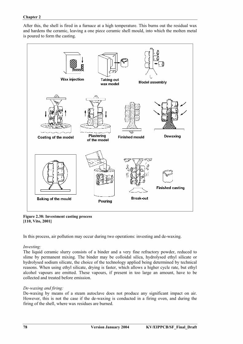
Chapter 2
78 Version January 2004 KV/EIPPCB/SF_Final_Draft
After this, the shell is fired in a furnace at a high temperature. This burns out the residual waxand hardens the ceramic, leaving a one piece ceramic shell mould, into which the molten metalis poured to form the casting.
Figure 2.38: Investment casting process[110, Vito, 2001]
In this process, air pollution may occur during two operations: investing and de-waxing.
Investing:The liquid ceramic slurry consists of a binder and a very fine refractory powder, reduced toslime by permanent mixing. The binder may be colloidal silica, hydrolysed ethyl silicate orhydrolysed sodium silicate, the choice of the technology applied being determined by technicalreasons. When using ethyl silicate, drying is faster, which allows a higher cycle rate, but ethylalcohol vapours are emitted. These vapours, if present in too large an amount, have to becollected and treated before emission.
De-waxing and firing:De-waxing by means of a steam autoclave does not produce any significant impact on air.However, this is not the case if the de-waxing is conducted in a firing oven, and during thefiring of the shell, where wax residues are burned.

Chapter 2
KV/EIPPCB/SF_Final_Draft Version January 2004 79
This burning occurs often in a lack of air, which results in the formation of carbon blackparticles. These particles have to be collected and either destroyed by afterburning or removed.Ceramic filters have been successfully used for this purpose, as they suit the high temperature ofthe exhaust gases, but this very recent technology has not yet become widespread.
This technique is used e.g. for precision casting and art casting. It is generally not applied inlarge-scale foundries (>20 tonnes/day capacity), and therefore is mentioned here only forinformative reasons.
The ceramic shell process (patented as Replicast®) extends the quality and precision ofinvestment casting to larger components, using a combination of Lost Foam and investmentcasting principles. The technique uses an inert, fired ceramic mould. To create the mould, anexpanded polystyrene replica of the required component is produced, which is dimensionallyprecise and of a high surface finish. No parting lines or cores are required, nor draft angles, andpolystyrene replicas can be glued together to create complex geometries. The polystyrene isburnt out before casting, allowing a wide range of alloys to be cast in the mould - from ultra lowcarbon stainless steel to nickel based alloys. This is in contrast to the Lost Foam process whereliquid metal consumes and replaces the polystyrene pattern, making it unsuitable for the vastmajority of steel components (polystyrene is 92 % by weight carbon).[219, Castings Technology International, 2003]
2.6 Casting
Pouring is the central activity in casting production. The finished mould is filled with the liquidmetal under the effects of gravitational or centrifugal forces or pressure. After pouring thecasting is cooled to allow solidification and is then removed from the mould for further coolingand treatment.[32, CAEF, 1997]
2.6.1 Casting in lost moulds
2.6.1.1 Pouring
There are two types of ladle generally used in pouring liquid metal: lip and teapot ladles. A thirdtype (i.e. the bottom ladle) is more specific to steel.
- Lip pour: In this type of ladle (Figure 2.39) the metal is charged over the lip, with the flowcontrolled by tilting the ladle using a geared handwheel. Since the metal flows from the topof the ladle, the metal surface must be slag-free or a skimmer must be used to prevent slagentering the mould. Lip pour ladles are used for pouring small steel castings

Chapter 2
80 Version January 2004 KV/EIPPCB/SF_Final_Draft
Figure 2.39: Lip pour ladle for molten metal pouring[237, HUT, 2003]
- Teapot ladles: As depicted in Figure 2.40, a refractory dam before the ladle lip ensures thatthe metal is drawn from the bottom of the ladle, so that the stream is slag free. The moltenmetal is generally cleaner than from a lip pour ladle. One disadvantage is that the narrowspout may occasionally permit the liquid steel to freeze if the heat is tapped cold or ifpouring is prolonged
Figure 2.40: Teapot ladle for molten metal pouring[237, HUT, 2003]
- Bottom pour ladles: The ladle is fitted with a pouring nozzle in its base, closed by arefractory stopper rod. The metal is drawn from the bottom and is therefore slag-free andnon-metallics, such as deoxidation products, are able to float out of the melt. The metalstream flows downwards, so that there is no movement of the stream during pouring. Thedisadvantage is that the velocity and the rate of flow change during pouring as theferrostatic head changes.

Chapter 2
KV/EIPPCB/SF_Final_Draft Version January 2004 81
Figure 2.41: Bottom pour ladle for molten metal pouring[237, HUT, 2003]
Automatic casting lines are often equipped with a pouring furnace. The working principlebehind one example furnace is depicted in Figure 2.42. The casting line halts when a mould is inthe correct position, i.e. under the pouring exit. Metal is poured during a fixed period byelevating a stopper. Because the metal level in the casting recipient is held constant, a fixedvolume of molten metal is poured into the mould. The metal level in the furnace is controlled bya floating device, which controls the gas pressure inside the furnace. The casting furnace isrefilled with metal from the melting furnace at fixed time intervals.[110, Vito, 2001], [174, Brown, 2000]
Figure 2.42: Pouring furnace[110, Vito, 2001]
2.6.1.2 Solidification (1st cooling)
The poured moulds are transported along the moulding line onto the cooling lines. The length ofthe cooling line determines the final temperature of the casting at the point of shake-out. Thistemperature must be low enough to provide the casting with sufficient strength during shake-outand further manipulation.

Chapter 2
82 Version January 2004 KV/EIPPCB/SF_Final_Draft
Big moulds are not moved during cooling. The cooling time can be up to several days.[110, Vito, 2001]
2.6.1.3 Shake-out
In the case of individual moulding, clay or chemically bonded moulds can usually be destroyedby vibration. In most cases this is accomplished by placing the moulding box on a vibratinggrate, using a crane to do this. As a result of the vibration, the sand is separated from the castingand the moulding box. The casting and moulding box remain on the grate rods, whereas thesand falls through and is subsequently reprocessed. The casting is usually transported to acooling area for further cooling in ambient air (second cooling).
A similar shake-out procedure is often carried out in mechanised systems and older low-capacity automated systems (Figure 2.43). Here the moulding boxes are removed fromconveyor belts, by means of hoists or other transfer equipment, and placed on vibrators. Finally,the castings are left to cool down or placed in a casting cooling device. In many systems, thesand casting is pressed out of the moulding box and a subsequent controlled cooling of thecastings and sand is achieved in combined or separate cooling devices, such as in coolingdrums, swing pipes, chain conveyors, fluidised bed coolers, etc.
Figure 2.43: Shake-out at the end of an automated moulding line[237, HUT, 2003]
Vacuum bonded sand moulds are destroyed by releasing the vacuum. The casting bucket ormoulding box, containing the loose sand and the casting, is emptied and then the casting iscooled by one of the described methods.[32, CAEF, 1997]
2.6.1.4 Casting cooling (2nd cooling)
The controlled cooling of castings and sand is carried out in rotary drums, swing drums or onoscillating conveyor troughs. The casting is cooled in oscillating conveyors or in cable-carbaskets. In many cases an airflow, which is often directed in the opposite direction to that of thecasting, is used for cooling. In some cases, fine water jets are used in order to increase thecooling effect.
2.6.2 Casting in permanent moulds
2.6.2.1 Gravity and low-pressure die-casting
Gravity and low-pressure die-casting make use of a permanent steel die into which the melt ispoured under the influence of gravity or a low-pressure gas. Sand cores can be used to formundercuts and complex interior shapes in the casting. Due to the rapid solidification process,permanent mould castings have a dense fine-grained structure with good strengthcharacteristics.

Chapter 2
KV/EIPPCB/SF_Final_Draft Version January 2004 83
The principle of low-pressure die-casting is shown in Figure 2.44. A metal die is mounted abovea sealed furnace containing molten metal. A refractory-lined riser tube extends from the bottomof the die into the molten metal. When air is introduced into the furnace under low pressure(15 – 100 kPa) the molten metal rises up the tube to flow into a die cavity with low turbulence,the air in the die escaping through vents and the parting lines of the die. When the metal hassolidified, the air pressure is released, allowing the still-molten metal in the riser tube to fallback into the furnace. After a further cooling time, the die is opened and the casting extracted.Due to the absence of feeders and risers, the casting yield is exceptionally high, generally over90 %. A good dimensional accuracy and surface finish are possible and complex castings can bemade using sand cores. This technique is typically used for aluminium castings, e.g. automotiveparts such as wheels, cylinder heads, and electric motor housings, and for domestic kitchenware.The die must be coated to optimise the casting release and cooling. In general, a die coating isapplied once per shift. The die life is normally around 30000 – 50000 shots. An example of alow-presure die-casting machine is given in Figure 2.45.
Figure 2.44: The principle of a low-pressure die-casting machine[175, Brown, 1999]
Figure 2.45: Low-pressure die-casting machine[237, HUT, 2003]
In gravity die-casting, the molten metal is poured under gravity into a permanent mould or die.Gravity die-casting machines range from simple, hand operated rack and pinion die sets,

Chapter 2
84 Version January 2004 KV/EIPPCB/SF_Final_Draft
manually poured, to carousel machines, which usually have a tilting mechanism for filling thedie and which are often operated using a pouring robot. The dies are coated with a refractory-based coating, controll the cooling rate. The time before the casting can be extracted from thedie varies from 4 to 10 minutes depending on the type of casting. The process is thereforerelatively slow, compared to pressure die-casting. To achieve reasonable output rates, a manualoperator will operate 2 – 4 die sets in sequence, allowing an output of 30 – 60 castings an hour.Automatic carousel machines may have 4 – 6 stations with multiple die sets, allowingproduction rates of around 1 casting per minute to be achieved. The process is most widely usedin aluminium casting for series’ of 1000 to more than 100000 pieces per year for e.g. manifolds,cylinder heads, water pumps.
Permanent mould coatings are typically formulated using water as a carrier, a high temperaturebinder (normally sodium silicate) and a refractory filler or blend of fillers. There are twocategories of coatings:- insulating: containing blends of insulating minerals such as talc, mica, kieselguhr, titanium
dioxide, alumina, etc.- lubricating: based on colloidal graphite or boron nitride to aid release of the casting.
Coatings are generally sprayed onto the die. Careful attention to die preparation, coatingpreparation and application and the type of coating equipment utilised can yield significantquality and productivity benefits.[175, Brown, 1999]
2.6.2.2 High-pressure die-casting
The term “die-casting” often implies “high-pressure die-casting”. The process utilises apermanent die (metal mould) into which molten metal is forced under high pressure. Theapplication of high pressure causes a high and turbulent metal flow, which allows theproduction of castings with high surface areas and low wall thicknesses. Dies are usually madefrom two blocks of steel, each containing part of the cavity, which are locked together while thecasting is made. Due to the high metal pressure, the maximum size of the casting is limited bythe maximum locking force of the casting halves. Retractable and removable cores are used toform internal surfaces. Due to the high metal pressures, only metal cores can be used. Thislimits the complexity of the casted piece. The metal is held under pressure until it cools andsolidifies. The die halves are then opened and the casting is removed, usually by means of anautomatic ejection system. Dies are preheated and lubricated before being used, and are eitherair- or water-cooled to maintain the desired operating temperature. Two basic types of high-pressure die-casting (HPDC) machines are used: hot-chamber or cold-chamber (see Figure2.46).
Figure 2.46: Cold-chamber and hot-chamber high-pressure die-casting devices[42, US EPA, 1998]

Chapter 2
KV/EIPPCB/SF_Final_Draft Version January 2004 85
Hot-chamber HPDC machines comprise a molten metal reservoir, the die, and a metal-transferring device, which automatically withdraws molten metal from the reservoir and forcesit under pressure into the die. A steel piston and a cylinder system with a gooseneck is used tocreate the necessary pressure within the die. A gooseneck machine utilises a cast iron channel totransfer the molten metal from the reservoir to the die. Pressures can range from a few bar toover 350 bar. Hot-chamber techniques are mainly used for zinc alloys and magnesium alloys.
Cold-chamber HPDC machines have molten metal reservoirs separate from the casting machine.Just enough metal for one casting is ladled by hand, or mechanically, into a small chamber,from which it is forced into the die under high pressure. Pressure is produced through ahydraulic system connected to a piston, and is typically in the range of a few hundred bar to700 bar. In cold chamber machines, the metal is just above the melting point and is in a slush-like state. Since the metal is in contact with the piston and cylinder for only a short period oftime, the process is mainly applicable to aluminium alloys, and to a lesser extent magnesiumalloys, zinc alloys, and even high melting point alloys such as brasses and bronzes.
Proper lubrication of the dies and plungers is essential for successful high-pressure die-casting.The die lubrication affects the casting quality, density, and surface finish, the ease of cavity fill,and the ease of casting ejection. Proper lubrication can also speed up the casting rate, reducemaintenance requirements, and reduce the build up of material on the die face. Althoughspecific formulations are proprietary, in general, lubricants (also called release agents) are amixture of a lubricant and a carrier material. Formulations may also include additives to inhibitcorrosion, to increase stability during storage, and to resist bacterial degradation. Lubricatingmaterials are typically mineral oils and waxes in water emulsions. Silicone oils and syntheticwaxes are finding increased use. Both water-based lubricants and solvent-based lubricants are inuse today. Water-based lubricants however dominate the market (95 %). The lubricant isapplied to the open die by spraying, between each shot. Dilute solutions of lubricant are used(1:20 – 1:200 release agent:water ratio). Alternative electrostatic powder coatings are currentlybeing developed.
High-pressure die-casting is not applicable to steel and high melting point alloys. The techniquefinds widespread application for aluminium castings. Dies are expensive but can have a life of150000 shots. The process is therefore most suitable for long runs of castings. One majoradvantage of HPDC over other casting methods is that the castings produced can have verycomplex shapes. The ability to cast complex shapes often makes it possible to manufacture aproduct from a single casting instead of from an assembly of cast components. This can greatlyreduce casting costs, as well as the costs associated with fabrication and machining.Furthermore, HPDC produces castings which have a high degree of dimensional accuracy andsurface definition compared to other casting methods, which may help to reduce or eliminatecostly machining steps. Finally, castings with relatively thin wall sections can be producedusing the HPDC method. This can result in substantial savings in material costs and reductionsin component weight.
Relatively little waste is generated in the actual HPDC process compared to other metal castingprocesses. However, some gaseous and fume emissions occur during metal injection. Metaloxide fumes are generated as some of the metal vaporises and condenses. Gaseous emissionscan originate from: the molten metal itself; the evolution of chemicals from the lubricant as it issprayed onto the hot metal die and as it contacts the molten metal. Emissions to water mayoccur from any leakage or spillage of hydraulic oil or heating oil and from cooling water.[42, US EPA, 1998], [128, IHOBE, 1998], [175, Brown, 1999], [225, TWG, 2003]

Chapter 2
86 Version January 2004 KV/EIPPCB/SF_Final_Draft
2.6.2.3 Centrifugal casting
In centrifugal casting, a permanent mould rotates at high speed around its axis as the metal ispoured. The speed of rotation and the metal pouring rate vary with the alloy and the size andshape being cast. The rotating axis is generally horizontal or under a small angle (Figure 2.47).Some specific devices apply rotation around a vertical axis. The resulting material has a verydense structure and properties that cannot be obtained with sand casting.
This technique is used to produce cylindrical products in cast iron, steel, and in alloys ofaluminium, copper and nickel. Typical parts made by this process are pipes, boilers, pressurevessels, flywheels, cylinder liners and other parts that are axisymmetric.[179, Hoppenstedt, 2002]
Figure 2.47: Schematic representation of a centrifugal casting machine[179, Hoppenstedt, 2002]
2.6.2.4 Continuous casting
Continuous casting is a high productivity device for the production of bars, tubes and profiles,where through rapid cooling, a fine-grained material with good mechanical properties isobtained. In continuous casting, the molten metal is cast into a water-cooled die, which is openat the bottom or at the side (Figure 2.48). The die gives the desired form to the product. Throughintensive cooling, the outside of the metal product solidifies, while it is slowly pulled out of themould. Through continuous pouring and extraction as the product is pulled out of the mould, theproduct gets longer. A burner cuts the product whenever the desired product length is reached.This technique is used for both ferrous and non-ferrous casting. The technique is used for thecasting of bars, slabs and sheets as a final step in iron, steel and non-ferrous metals production.Its use in this context is described in the BREF for non-ferrous metal industries [155, EuropeanIPPC Bureau, 2001] and the BREF on iron and steel production [211, European IPPC Bureau,2000].

Chapter 2
KV/EIPPCB/SF_Final_Draft Version January 2004 87
Figure 2.48: Schematic representation of a thread casting machine used for continuous casting[179, Hoppenstedt, 2002]
2.7 Finishing and post casting operations
Finishing of the raw castings encompasses all necessary treatments to yield a finished product.According to the process, various steps may be required, such as:
- removal of the running system- removal of residual moulding-sand from the surface and core remains in the casting cavities- removal of pouring burrs- repair of casting errors- preparation of the casting for mechanical post-treatment, assembly, thermal treatment,
coating, …
In some cases, foundries also perform assembly, surface finishing and coating of the castings.However, these activities are not discussed in this document. Surface finishing and coatingtechniques are discussed in the BREF documents on Surface Treatment of Metals (STM BREF)and on Surface Treatment Using Solvents (STS BREF).[110, Vito, 2001], [225, TWG, 2003]
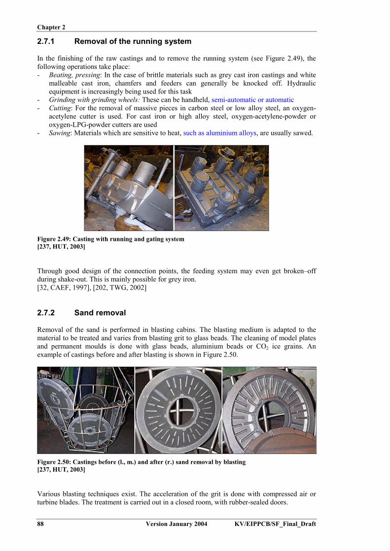
Chapter 2
88 Version January 2004 KV/EIPPCB/SF_Final_Draft
2.7.1 Removal of the running system
In the finishing of the raw castings and to remove the running system (see Figure 2.49), thefollowing operations take place:- Beating, pressing: In the case of brittle materials such as grey cast iron castings and white
malleable cast iron, chamfers and feeders can generally be knocked off. Hydraulicequipment is increasingly being used for this task
- Grinding with grinding wheels: These can be handheld, semi-automatic or automatic- Cutting: For the removal of massive pieces in carbon steel or low alloy steel, an oxygen-
acetylene cutter is used. For cast iron or high alloy steel, oxygen-acetylene-powder oroxygen-LPG-powder cutters are used
- Sawing: Materials which are sensitive to heat, such as aluminium alloys, are usually sawed.
Figure 2.49: Casting with running and gating system[237, HUT, 2003]
Through good design of the connection points, the feeding system may even get broken–offduring shake-out. This is mainly possible for grey iron.[32, CAEF, 1997], [202, TWG, 2002]
2.7.2 Sand removal
Removal of the sand is performed in blasting cabins. The blasting medium is adapted to thematerial to be treated and varies from blasting grit to glass beads. The cleaning of model platesand permanent moulds is done with glass beads, aluminium beads or CO2 ice grains. Anexample of castings before and after blasting is shown in Figure 2.50.
Figure 2.50: Castings before (l., m.) and after (r.) sand removal by blasting[237, HUT, 2003]
Various blasting techniques exist. The acceleration of the grit is done with compressed air orturbine blades. The treatment is carried out in a closed room, with rubber-sealed doors.

Chapter 2
KV/EIPPCB/SF_Final_Draft Version January 2004 89
The castings are suspended on a monorail and move batch wise through the blasting cabin. Forsmaller pieces, a specific moving belt is used. Big pieces are blasted manually, using a lance inan enclosed cabin. In this case, personal safety measures are very important. A helmet with adust mask and respiratory equipment are required.
The coarse dust (sand and metal flakes) that is generated by blasting of the workpiece, iscollected together with the grit. It is dedusted, magnetically separated and sieved. The finefraction is removed from the exhaust air together with the coarse fraction, using a bag filter.Cleaning of the grit before internal re-use is of major importance as the presence of sand couldcause a quick wearing of the throwing shovels.
2.7.3 Removal of burrs
Burrs, which occur at the point where mould and core pieces join, at veins and at other surfaceirregularities, are removed using grinding wheels and grinding stones. Grinding wheels arehandheld, whilst with grinding stones the casting is pressed against a rotating stone.
Other applied techniques include:- Slide grinding: Grinding burrs and small amounts of other excess material on the casting
surface can be removed without hand grinding. The parts are revolved in drums or vibratingcontainers together with abrasive shapes, causing them to be rubbed against each other andagainst the abrasive wheels. In a typical unit the castings are ground using a bed ofpyramidal grinding stones, together with the addition of a water-soap emulsion. Theroughness and the size of the grinding stones vary depending on the size of the castings
- Tumbling: This technique, also called blast removal, is used to remove thin burrs or smallamounts of casting residue. During this process the burrs remove themselves in an airlessblast cleaning process as a result of the parts being impacted together in a rotating drum. Atthe same time the edges are rounded-off. Sometimes the process is assisted by a liquid.
Figure 2.51: Burrs (l.) and their removal using a grinding stone (m.) and slide grinding (r.)[237, HUT, 2003]
Automation of these operations is difficult due to the variability in shape of the burrs and theneed to fix the casting easily and quickly. Nevertheless, automatic grinding machines areincreasingly being used in serial production. Raw casting parts are inserted into such machinesto produce suitably worked parts which do not need any retooling or further manual grindingwork.
Furthermore the following techniques are applied in automated lines:- Punching: Due to the use of cutting and forming techniques, serial casting parts are often
designed in such a way that the unavoidable burr occurs in predetermined amounts whichare easily accessible as far as processing is concerned. If the series is large enough,dedicated punching tools can be designed to quickly remove the burr and to provide thecasting with a uniform contour

Chapter 2
90 Version January 2004 KV/EIPPCB/SF_Final_Draft
- Milling: With the development of electronic controls for processing machines it has becomeincreasingly easier to compile programs with which to process individual workpieces. Thusit is possible to use milling machines for smaller series instead of the punching machineswith their single purpose tools. During such a process, the workpieces are taken up by thedevice and passed across a number of different milling machines.
Finally, welding may be carried out in order to join castings, as well as to manufacture andrepair casting flaws. In most of these cases, arc welding is used. Depending on the requirementsand equipment, the work is carried out either with hand operated stick electrodes or withwelding wire and with or without inert gas. Scarfing is used on steel castings, which consists inapplying grooves for stress relieve. This uses a cutting torch with a copper-coated carbonelectrode.[32, CAEF, 1997], [110, Vito, 2001], [202, TWG, 2002]
2.8 Heat treatment
2.8.1 Introduction
For ferrous castings, there are basically two types of thermal treatments which can be applied:annealing and hardening. In the case of annealing, the tension caused in the workpiece as aresult of pouring, and the subsequent cooling down of the casting, is reduced and the structure isevened out. In the case of hardening, the level of heat is raised above the transformationtemperature and the workpiece is subsequently rapidly cooled, in a process known asquenching. This causes the material properties to change. Different results may be obtained bythe use of water, oil or air quenching. ‘Quench and temper’ is the name of the procedure inwhich the workpiece is reheated to the tempering temperature following quenching, and thequenching procedure is repeated.
The malleableising of iron is a thermal treatment which differs from annealing and hardening.Here, the malleable unfinished casting is either transformed to a white or black temperaturecasting depending on the procedure.
Many non-ferrous castings are used in an ‘as-cast’ condition, but certain applications requirehigher mechanical properties than ‘as-cast’ material. Possible treatments are annealing,controlled cooling, solution heat treatment, artificial ageing and precipitation treatment.[32, CAEF, 1997], [175, Brown, 1999]
2.8.2 Heat treatment furnaces
2.8.2.1 Chamber furnaces
Chamber furnaces are the most common furnace construction. Their actual design has beenadapted in many sub-forms in order to meet the needs of the differing thermal treatments ofvarious types of casting and production. Some examples of chamber furnaces are bogie hearthfurnaces, top hat furnaces, hub open-hearth furnaces, etc. Chamber furnaces with continuallyrunning conveyance means are called tunnel furnaces. Heating is provided either electrically, orwith gas or fuel oil.
For non-ferrous materials, some heat treatments are carried out close to the melting point of thecasting, so accurate temperature control is needed. Forced air circulation is used to ensure thatthe temperature at all parts of the furnace is constant and equal.[32, CAEF, 1997], [175, Brown, 1999]

Chapter 2
KV/EIPPCB/SF_Final_Draft Version January 2004 91
2.8.2.2 Shaft furnaces
Pipes, long waves and similar parts are often treated while suspended in a vertical position inshaft furnaces. In shaft furnaces, the heating is provided by electricity, gas or fuel oil.
2.8.2.3 Annealing furnaces
Chamber, top hat or tunnel furnaces are used to temper unfinished castings. The heating of suchfurnaces is carried out via electricity, gas or fuel oil.
2.8.3 Quenching
In thermal treatment processes, chilling is the cooling down of a workpiece at a greater speedthan in calm air. This can be achieved by means of a rapid submersion in water or oil (seeFigure 2.52), as well as by forced air-cooling. Care should be taken that the workpieces arecooled at a uniform rate. When submersing in fluids, either the parts must be moved or the fluidmust be continually circulated to ensure a full and even cooling of all parts of the workpiece. Ina similar principle, in air quenching the blowing procedure must be arranged so that the aircovers the entire surface.
Figure 2.52: Quenching of a hot casting shortly after heat treatment[237, HUT, 2003]
2.8.4 Heat treatment of ductile iron (SG iron)
It is obviously desirable to achieve the required metal properties in the ‘as-cast’ form to savefurther treatments being necessary, but this is not always possible because of variations insection thickness, etc. The heat treatment of the castings can eliminate carbides in thin sections,produce more consistent matrix structures and for a given structure, often improve its

Chapter 2
92 Version January 2004 KV/EIPPCB/SF_Final_Draft
mechanical properties, especially by normalising the grain structure. Where tempered martensitestructures are needed, heat treatment is essential.[32, CAEF, 1997], [174, Brown, 2000]
2.8.4.1 Stress relief
Stress relief consists of heating the castings at a rate of 50 – 100 ºC/h to 600 ºC (taking care notto exceed 610 ºC), followed by soaking them for a minimum of one hour, plus an extra hour forevery 25 mm of section thickness in the thickest section, and then cooling them at a rate of50 - 100 ºC/h or less. The castings must be adequately supported in the furnace so that they arenot subjected to stress.
2.8.4.2 Breakdown of carbides
Thin section castings may contain carbides in the ‘as-cast’ structure. These can be eliminated bysoaking the castings at 900 – 925 ºC for 3 to 5 hours.
2.8.4.3 Annealing to produce a ferritic matrix
Annealing involves soaking the castings at 900 – 925 ºC for 3 – 5 hours, followed by a slowcooling at around 20 – 35 ºC/h through the critical temperature range (about 800 – 710 ºC), andfinally furnace cooling at, say 50 – 100 ºC/h to 200 ºC.
2.8.4.4 Normalising to produce a pearlitic matrix
For normalising, a soaking of the castings above the critical temperature followed by air coolingis necessary. Again a soaking temperature of 900 – 925 ºC is usually used, to ensure that thecarbides are broken down. Forced air cooling is used to form pearlite. The type of heat treatmentfurnace available and the size of the load determines the process cycle that is possible. It may benecessary to adjust the metal composition with tin or copper to help the formation of fullypearlitic structures.
2.8.4.5 Producing hardened and tempered structures
Hardened structures are produced by austenitising the casting at 900 – 920 ºC, followed by oilquenching. Tempering is usually carried out at 600 – 650 ºC.
2.8.4.6 Austempered ductile iron (ADI)
Austempering is an isothermal heat treatment for producing ausferrite structures. It can doublethe strength of ductile iron whilst allowing it to retain good ductility and toughness. Wearresistance and fatigue properties are excellent, even to such a degree that ADI is comparablewith wrought and hardened-tempered steel.
The ADI heat treatment is a two-stage process, as shown in Figure 2.53. Austenitising is carriedout at 815 – 930 ºC to fully transform the matrix to austenite. This is done either in a non-oxidising atmosphere furnace or in a high temperature salt bath. Temperatures and times aredetermined by the chemical composition, the section size and the grade of ADI required; 1 to1.5 hours is usually adequate. Slow initial heating of the casting is desirable to avoid the risk ofcracking the complex shapes. The castings are then quenched to the required isothermal heattreatment temperature, usually between 210 and 400 ºC. This is usually done in a salt bath. The

Chapter 2
KV/EIPPCB/SF_Final_Draft Version January 2004 93
castings are held at this temperature for 1 – 2 hours to complete the transformation ofaustenite to ausferrite. Lower temperatures give high hardness, strength and wear resistance,while higher heat temperatures result in higher ductility and toughness. After the isothermaltreatment, the castings are cooled to ambient temperature.
Figure 2.53: Typical austempering heat treatment stages[174, Brown, 2000]
Unalloyed ductile irons may be austempered in sections of up to about 8 mm thickness. Thickersection castings require the addition of Mo or Ni to increase the hardenability.
Austempered ductile iron is used as a replacement for forged steel components in theagricultural, railway, automotive and general engineering industries; for example, for ploughtips, digger teeth, spring brackets, rear axle brackets, gears, etc. ADI production is growing butits use is limited to some extent by the lack of suitable heat-treatment facilities.[32, CAEF, 1997], [174, Brown, 2000]
2.8.5 Heat treatment of steel
Steel castings are normally subject to a heat treatment before delivery, e.g. normalising, withthis heat treatment leading to a structural change. Additionally, potential casting stresses have tobe reduced (stress relief annealing). Many steel casting qualities have to be additionallytempered after stress relief anneal (hardening and tempering).
Most steel castings are subjected to a heat treatment to attain the desired mechanical propertiesand to a stress relief, to obtain the right corrosion resistance and to avoid the difficulties duringthe finishing operations. The heat treatment is defined according to the steel grade. To removethe chemical and structural segregations, annealing at high temperature is generaly performed.Carbon and low alloy steels undergo:- normalising and air cooling, or- austenitising, quenching and tempering.
Austenitic or duplex stanless steels undergo a solution annealing and water quenching heat-treatment. Additionnal heat-treatments such as for stress relief or post weld treatment are alsoused to eliminate the internal stresses of the material.[32, CAEF, 1997], [202, TWG, 2002], [225, TWG, 2003]

Chapter 2
94 Version January 2004 KV/EIPPCB/SF_Final_Draft
2.8.6 Heat treatment of aluminium
Aluminium castings are heat treated for: homogenisation, stress relief, improved dimensionalstability and machinability, optimised strength, ductility, toughness and corrosion resistance.Most often the heat treatment is a compromise between varying effects, maximising theimportant properties of one often at the expense of others. The heat treatment of aluminium mayinvolve: annealing, solution heat treatment, quenching, artificial ageing and precipitationtreatment. The type of treatment applied is indicated by a suffix to the alloy designation. This iscalled the temper designation. For sand, gravity and low-pressure die-castings all treatments arepossible, though not all are standardised. Pressure die-castings are not solution treated andquenched in the same way as sand, gravity and low-pressure die-castings. Entrapped gasbubbles can expand and cause casting defects. Heat treatment is not a common step for high-pressure die-castings; only about 1 % of this type of castings are subjected to heat treatment. Alldie-castings may be quenched from the die, precipitation treated and stress relieved withoutsuffering any harmful effects. In the low pressure die casting production of aluminium wheels90 % of the castings are subjected to heat treatment[225, TWG, 2003].
2.8.6.1 Stress relieving and annealing
Castings with changes of section, or of a complex shape are likely to develop internal stresses.These can then cause dimensional changes upon machining. To stabilise the casting and toremove internal stresses, castings are heated to a temperature of 200 ºC for 5 hours, followed byslow cooling in the furnace.
2.8.6.2 Solution treatment and quenching
Castings are heated at temperatures just below the melting temperature and held there for a longtime to take the alloying constituents into a homogeneous solid solution. The castings are thenrapidly cooled by quenching to room temperature to retain the elements in solution. Water orspecial quenchants are used. The quench tanks are placed close to the furnace to ensure thatrapid cooling is possible. Although sensitivity to the quench interval differs between alloys,good practice should limit the interval to 5 – 10 s.
2.8.6.3 Precipitation treatment
The controlled precipitation of alloying constituents is promoted by heating the casting to atemperature of between 150 ºC and 200 ºC. The casting strength and hardness are increased.The process is therefore also referred to as structural hardening. Each alloy has an optimal heattreatment cycle.
2.8.6.4 Artificial ageing
Some casting alloys increase in strength and hardness while left standing at room temperature.The process can take several weeks but can be speeded up by heating above room temperatureand then sustaining this heat over time.[175, Brown, 1999], [202, TWG, 2002], [213, CTIF and CQRDA, 2002], [212, Zalensas, 1993]

Chapter 2
KV/EIPPCB/SF_Final_Draft Version January 2004 95
2.9 Quality control
During quality control the finished casting is checked for compliance with the productrequirements concerning e.g. dimensions, metal structure defects, surface structure. Dependingon the type of casting and the size of the series, quality control can be achieved by visualinspection, with the use of measurement tools, or automatically.
In the production of aluminium wheels the castings are controlled via X-ray analysis. Astandard image of a good casting is used for verification by a computer program. If there are anydifferences, the image is studied and assessed by a human operator. Random tests of the alloyare analysed with spectral analysis.
The quality control procedure informs the final decision to reject a casting or to allow its furthershipment to the market. Rejected castings are brought back to the raw material input to beremelted.[225, TWG, 2003]


Chapter 3
KV/EIPPCB/SF_Final_Draft Version January 2004 97
3 CURRENT EMISSION AND CONSUMPTION LEVELS INFOUNDRIES
3.1 Mass stream overview
3.1.1 Introduction
The general mass stream overview for the foundry process is given in Figure 3.1. This schemegenerally applies for ferrous and non-ferrous foundries. Specific aspects of the various processsteps and types will be worked out below.
Foundry ProcessMelting - Casting - Finishing
Metalscrap/ingots
Castings
Energy- fuel- electricity- heat Water
- cooling- scrubbing
Sand and Chemicals- additives melting and metal treatment- binders/release agents- oils and lubricants
Noise
Water- organics- metal dust
Solid- dust- used sand- dross - slag
Energy- heat- steam- hot water
Air- combustion and reaction products- particulate matter- pyrolysis and evaporation products
Odour
Figure 3.1: Mass stream overview for the foundry process
3.2 Melting and the metal treatment of ferrous metals
3.2.1 Properties of melting furnaces for steel and cast iron
Table 3.1 presents an overview of the typical properties of melting furnaces used for steel andcast iron. The data is then discussed in the sections below.

Chapter 3
98 Version January 2004 KV/EIPPCB/SF_Final_Draft
Process Steel Cast IronType ELECTRIC ARC FURNACE INDUCTION F. INDUCTION F. CUPOLA FURNACE ROTARY F.Subtype Acid lined Basic lined Coreless Coreless Cold blast Hot blast Hot blast –
long campaignCokeless - duplex
Energy source Electricity Electricity Electricity Electricity Coke Coke Coke Gas/fuel Gas/fuelThermal efficiency1(%) 60 – 70 60 – 70 50 – 60 50 – 60 30 – 40 40 – 45 35 – 45 50 – 60 50 – 60Primary thermalefficiency2(%)
21 – 25 21 – 25 15 – 20 15 – 20 30 – 40 40 – 45 35 – 45 45 – 50 35 – 453
kWh/tonne metal charge 500 – 700 500 – 700 520 – 800 520 – 800 950 – 1200 800 – 900 810 – 1100 700 – 800 600 – 800Batch/continuous Batch Batch Batch Batch Continuous Continuous Continuous Continuous BatchProduction rate4
(tonnes/h)2 - 10 8 - 70 8 - 70 >5
Furnace capacity5
(tonnes)2 – 50 2 – 50 0.01 – 30 0.01 – 30 1 – 20
Meltdown time (h) 1 – 4 1 – 4 1 – 2 1 – 2 2 – 4Refining ability Possible Possible No No Yes Yes Yes No NoCapital cost High High High High Medium High High Medium LowSlag production(kg/tonne metal charge)
10 – 40 20 – 80 10 – 20 40 – 80 40 – 80 40 – 80 20 – 60
Dust production6
(kg/tonne metal charge)5 – 8 0.06 – 1 5 – 13 4 – 12 0.8 0.3 – 2.9
Waste gas7 emission(kg/tonne metal charge)
CO28 Depending on power generation Depending on power generation 400 – 500 350 – 480 100 – 120 120
CO 7.5 – 25 (decarburisation) n.a. Possible9 0.5 – 2.5 <10 1.0 – 1.5SO2 <1 Minor 1 – 2 <1 Fuel dependent 2.5 – 3.0NOx n.a. n.a. <1 <1 0.5 0.3 – 0.41 Indicated values give an order of magnitude but largely depend on exploitation conditions, such as metal temperature, furnace capacity and production rate2 Efficiency of electrical power generation assumed to be 35 %3 Taking into account energy consumption for oxygen production and the raw materials, such as graphite and FeSi, to substitute the oxidised elements during melting4 For continuous processes only5 For batch processes only6 Indicated values are general values found in literature7 Indicated values are general values found in literature8 Assuming complete combustion9 Depending on local exploitation conditions and construction.
Table 3.1: Typical melting furnace properties and emission data[32, CAEF, 1997], [110, Vito, 2001], [202, TWG, 2002], [225, TWG, 2003] and comments from CTIF

Chapter 3
KV/EIPPCB/SF_Final_Draft Version January 2004 99
3.2.2 Cupola furnaces
Input Output� ferrous material (iron pigs, sponge iron, steel
scrap, foundry returns …)� alloying metal (ferro-alloys …)� flux (limestone…)� energy (coke, gas, oil, electricity)� oxygen� cooling water� water
� metal alloy (cast iron)� dust (metal content)� CO/CO2, SO2, NOx
� HF� Dioxins, furans� organic pollutants� slag� waste refractory
3.2.2.1 Coke and energy consumption
In cold blast operation, the coke consumption between the charges is generally90 - 120 kg/tonne metal charge, but can be less than 70 kg/tonne metal charge, e.g. in the caseof counterweights. Accounting for the amount of coke in the bed gives a total coke consumptionof 110 – 140 kg/tonne metal charge. As the calorific value of European cokes is 8.5 kWh/kg,this corresponds to a calorific input of 950 – 1200 kWh/tonne metal charge.
The total coke ratio in a hot blast cupola is generally 110 – 145 kg/tonne metal charge.However, as the average steel percentage is 50 %, and the recarburisation consumes about1.5 %, the real burned coke ratio is 95 – 130 kg/tonne metal charge, which is 810 to1100 kWh/tonne metal charge. This corresponds to a thermal efficiency of 35 to 45 %.
Depending on the plant layout, the energy consumed by the fume treatment equipment and theholding furnace, as given in Table 3.2, must be added. German data indicate a specificelectricity use for the flue-gas cleaning equipment of c. 20 kWh per tonne of good casting. [202,TWG, 2002]
Energy carrier type Average consumptionkWh/tonne metal charge
Gas for the combustion chamber 40Electricity for the flue-gas cleaning equipment(fans, etc.)
40
Electricity for the holding furnace 60
Table 3.2: Average energy consumption for off-gas treatment and holding
3.2.2.2 Particulate matter
The emission range of particulate matter is very wide. Particulate emissions depend primarilyon the cupola type used, as shown in Table 3.3:
Cupola type Dust emission(kg/tonne metal
charge)
Coke proportion(kg/tonne metal
charge)Cold blast 5 – 13 110 – 140Hot blast 4 – 10 95 – 130Liningless hot blast 5 – 12 115 – 135Cokeless 0.8 0
Table 3.3: Dust emission levels (raw cupola off-gas) from various cupola types[32, CAEF, 1997]

Chapter 3
100 Version January 2004 KV/EIPPCB/SF_Final_Draft
Dust emission levels measured at the stack for three German furnaces are given in Table 3.4.
Flue-gas cleaning Volume(m³/h)
Total dust(mg/m³)
PM10(%)
PM2.5(%)
Above charge hole off-take; bag filter 28500 7 88 47Cyclone, Venturi, recuperator 16000 68 – 94 96 88n.d 6000
(Nm³/h dry)75 100 45 – 85
Table 3.4: Cupola dust emission levels and PM size distribution[202, TWG, 2002]
In general, particle sizes range from less than 1 µm up to 10 mm, with 50 % less than 100µm.However, 5 to 20 % are smaller than 2 µm, which makes the dust collection more difficult.Cupola dust is primarily made up of coke, silica, rust and limestone, as shown in Table 3.5.
Substance Composition (%)[32, CAEF, 1997] [158, Charbonnier, et al., 1998]
Iron oxide 30 – 60 15 – 25SiO2 � 25 15 – 30Coke dust 3 – 15 n.dMnO 3 – 10 2 – 5Al2O3 1 – 3 2 – 5MgO 1 – 3 0 – 2CaO <1 5 – 10S <2 n.dZnO, depending on the charge <3 0 – 30 Zn*PbO, depending on the charge <1 0 – 5 Pb*
* In the form of oxides and silicates; applicable for Zn-enriched dusts
Table 3.5: Typical composition of cupola dust, data in weight per cent[32, CAEF, 1997] and [158, Charbonnier, et al., 1998]
3.2.2.3 Waste gases
Coke fired cupola gas is composed primarily of N2, CO2, H2O, and CO, with smaller amounts ofSO2. On conventional cupolas, where the off-gas is collected above the charging door, adistinction has to be made between the condition of the flue-gases below and above the chargingdoor, since ambient air is entrained through the open charge door. This input significantlychanges the total airflow.
If the cupola gases are hot enough, and if there is enough CO present, the gases may burnspontaneously together with drawn-in air (CO + O2 � 2CO2) and temperatures may rise to900 ºC. Little or no CO will then be left in the exhaust. If no combustion takes place, the airintake will result in a cooling effect, of between 100 and 300 ºC, and the CO/CO2 balance willremain unchanged. The temperature of the gases just below the charging door is primarilydependent on the charge height; the input of ambient air is determined by the fan capacity or thenatural draught available.
The flow of the undiluted cupola top gases is proportional to the coke consumption. Increasingthe coke proportion in the charge will decrease the production rate (tonne molten metal/h) if thesame blast airflow is maintained. It may then be necessary to increase the blast to maintain theproduction. The metal temperature will also increase. With reference to the combustion rate(C + O2 � CO2), more coke and blast air will result in an increased flow of exhaust gases.
For a given furnace, the coke and blast air consumption depend on the targeted melting rate andthe metal temperature, which can vary on an hourly basis. Typical flowrates reported in

Chapter 3
KV/EIPPCB/SF_Final_Draft Version January 2004 101
literature vary from 600 to 800 Nm3/tonne metal charge for cold blast cupolas and 500 to 700Nm3/tonne metal charge for hot blast cupolas. The composition of the unburned top gases maybe as follows (Table 3.6):
Substance Volume %CO2 10 – 18CO 5 – 15H2 <1SO2 <0.05N2 Remainder
Table 3.6: Unburned top gas composition for cupola furnace[32, CAEF, 1997]
Above the charging door, the flowrates of the exhaust gases may be two to five times higher,depending on the target temperature (which depends on the kind of dust arrestment systemapplied) of the diluted gases and, in the case of a recuperative hot blast cupola, the presence of apost combustion chamber. Typical flowrate values are 3000 to 4000 Nm3/tonne metal chargemelted for cold blast cupolas and 900 to 1400 Nm3/tonne metal charge when post-combustion isperformed. The composition of the gases is determined by the rate of dilution (natural draughtor fan power), the degree of spontaneous combustion of the CO, or the post combustion itself,which can be executed on the complete or partial flow.[32, CAEF, 1997]
Emission data for the main combustion gas components are given in Table 3.7. Hot blast andcold blast cupolas with varying melting capacities are listed. The table also indicates whetherthe off-gas is collected under or above the charging door. The hot blast systems show reducedSO2 emission levels. The disintegrator shows a better dedusting performance than the venturiscrubber. The application of post combustion clearly affects both the CO and NOx levels, underoptimal working conditions. Analysis of the full measurement campaign data shows that sub-optimal operation of a hot blast cupola results in increased CO-emissions: 2000 mg/Nm³,compared to 5 – 20 mg/Nm³ in optimised conditions. VOC and PAH emissions rise accordingly.[110, Vito, 2001]
The use of dry dedusting (i.e. using a bag filter) results in dust emission levels �20 mg/Nm³.Inventory data from Italian foundries showed a dust level below 30 mg/Nm³ (ranging from0.1 to 32 mg/Nm³) when a bag filter was applied. Wet scrubbing gives dust emissions up to80 mg/Nm³ (ranging from 5.4 to 78 mg/Nm³) [180, Assofond, 2002]. A value of 68 – 94 mg/m³was reported for a German cupola with wet scrubbing (see Table 3.4).

Chapter 3
102 Version January 2004 KV/EIPPCB/SF_Final_Draft
Cupola Capa-city
Exhaust Flow FGCequipment
Dust SO2 CO NOx HF O2
type tonne/h type m³/h mg/Nm³ mg/Nm³ mg/Nm³ mg/Nm³ mg/Nm³ vol %Hot blast1) 19 UC 29000 Venturi1) 41 21 17798 21 n.d 11Hot blast 20 UC 40000 Disintegrator 5 57 712 11 n.d 11Hot blast 24 UC 46445 Bag filter 1.1 –
1.420 14 – 17 70 – 75 7 11
Hot blast 25 UC 35000 Venturi 36 28 21 16 n.d 11Hot blast 60 UC 75000 Disintegrator 5 58 9 7 n.d 11Cold blast 3.2 AC 12000 Bag filter 10 401 5084 16 1 11Cold blast 5 AC 23000 Bag filter 6 434 28558 63 n.d 11Cold blast 8 AC 20000 Bag filter 20 401 936 36 n.d 11Cold blast 9 UC 22000 Bag filter 4 105 17286 60 n.d 111) Working with an old recuperatorUC: Under charge gas collection; AC: above charge gas collectionAll data are continuous monitored daily average values
Table 3.7: Emission data for hot blast and cold blast cupolas working with different set-ups[29, Batz, 1986], [202, TWG, 2002], data recalculated to 11 % O2
3.2.2.4 Cupola slag
Slags contain oxides that float upon the melt and which arise from impurities in the feedmaterial, wearing of the furnace refractory and from the ash of coke and from the melting lossof the metal charge [225, TWG, 2003]. Slags are bonded through the addition of binders, suchas vermiculite. The typical composition of cupola slag is given in Table 3.8. A cupola furnacetypically produces 40 – 80 kg slag per tonne of liquid iron.
Compound %SiO2 45 – 55CaO 25 – 40Al2O3 8 – 20MgO 1 – 3MnO 1 – 4FeO 1 – 6Sulphides <1TiO2 <1ZnO <0.1
Table 3.8: Typical cupola slag composition[172, Neumann, 1994], [156, Godinot, 2001]
Cupola slag consists of 30 % refractory material, 10 % sand (from internal scrap), 40 % CaO(flux), 10 % cokes ashes, and 10 % burn-off material.
An important aspect of cupola slag is its high SiO2-content. After quenching, the slag has avitrified structure. This generates an inert non-leaching material.
3.2.2.5 Waste refractory
The cupola furnace has the specific feature that the lining material (quartz-clay mixture) of thefurnace at the melting zone only lasts for one melting campaign. The main part of the refractoryis converted into slag. The amount to be taken out and disposed of as waste is much smallerthan the applied amount.

Chapter 3
KV/EIPPCB/SF_Final_Draft Version January 2004 103
3.2.3 Electric arc furnace
Input Output� ferrous material (steel scrap, foundry returns
swarf, pig iron …)� alloying metal (ferro-alloys …)� flux (limestone …)� energy (electricity, gas, oil)� oxygen� electrodes
� metal alloy (cast steel)� dust (metal content, refractory)� NOx, CO2, CO� organic air pollutants, HC� metal oxide fumes� slag (CaO, SiO2, MgO)� waste refractories
3.2.3.1 Input
500 – 600 kWh of electricity is used to melt and raise one tonne of steel to its castingtemperature. Furnaces are normally rated at 500 kVA per tonne, giving a melting time of about1.5 hours.
The electrodes are made of graphite and are consumed during operation through oxidation,volatilisation and breakage, so they must be replaced as necessary. A three tonne furnacetypically uses electrodes of 200 mm diameter. Electrode consumption is a significant factor inthe cost of arc melting and figures vary from 3 to 10 kg/tonne of steel melted depending on thetype of steel produced and the practice used. [174, Brown, 2000]
3.2.3.2 Particulate matter
Particulate emission rates reported in literature vary from 2 to 20 kg per tonne of iron chargedwith an average of 5 to 8 kg per tonne. The highest emission rates are recorded at the beginningof the melting cycle, during the decarburisation treatment and during back charging [173,Huelsen, 1985]. Particle sizes range from less than 1 µm up to 100 µm, with 50 % being lessthan 3 to 5 µm. During oxygen treatment, one analysis showed almost 90 % of the particleswere smaller than 5 µm.
In terms of the chemical composition of the particulate matter, an even bigger range ofmeasured data can be observed. Table 3.9 gives an overview of the reported figures in theliterature.
Substance Weight per cent (%)FeO + Fe2O3 30 – 60SiO2 5 – 35CaO 1 – 15MgO 0 – 15ZnO 0 – 16Cr2O3 0 – 8MnO 2 – 10Al2O3 0 – 5MoO3 <1NiO <1Pb <1Cd <0.01TiO2 <0.05V2O5 <0.05Ignition loss 0 – 4
Table 3.9: Chemical composition of EAF dust from steel foundries[32, CAEF, 1997]

Chapter 3
104 Version January 2004 KV/EIPPCB/SF_Final_Draft
The composition of the furnace dust primarily depends on the steel grade being produced. Forinstance, low alloy steels will not generate emissions containing chromium or nickel, whereasstainless steel will. Another important factor is scrap quality. Melting galvanised steel scrapleads to significant emissions of zinc oxide.
The application of an appropriate hooding of the furnace allows the capture of up to 98 % of thefurnace dust. The captured exhaust gas is then cleaned, usually using a bag filter. This reducesdust emission levels to below 10 mg/Nm³.[29, Batz, 1986]
3.2.3.3 Visible fumes
Visible fumes are emitted during charging of the hot furnace and at the beginning of the meltingcycle. The available literature does not report the quantities and the composition of thesesecondary emissions. Again, the nature of the fumes depends on the cleanliness of the chargedmaterial with respect to its oil, grease, paint or other organic matter content.
3.2.3.4 Waste gases
Electric arc furnaces are mainly used for steel melting. They primarily generate dust emissionsand gaseous compounds, such as nitrogen oxides, carbon monoxide and organic compounds.The organic compounds depend on the type and amount of impurities in the feed metal. The rawmaterials used as charge materials in the foundry are selected so that they don't usually containmaterials that can produce dioxins. Organic compounds are decomposed into harmless products,so long as no scrap preheating without post-combustion is applied. [29, Batz, 1986]
Emission data for the main combustion gas components are given in Table 3.10. Inventory datafrom Italian foundries showed a dust level below 10 mg/Nm³ (ranging from 1.2 – 8.3 mg/Nm³)when a bag filter is applied. Wet scrubbing gives dust emissions below 25 mg/Nm³ (rangingfrom 12 – 24.5 mg/Nm³). [180, Assofond, 2002]
Capacity Off-gas Flow FGC Dust SO2 CO NOx HF O2tonne/charge
collection m³/h equipment mg/Nm³ mg/Nm³ mg/Nm³ mg/Nm³ mg/Nm³ vol %
EAF 50 FH 265000 Bag filter 2 n.d n.d 50 n.d 20EAF 2 x 50 FH 380000 Bag filter 4 n.d n.d n.d n.d 20EAF 10 PH 160000 Bag filter 1 1 200 5 0.1 20FH: Full hooding; PH: Partial hooding
Table 3.10: Typical emission values for EAF furnaces[29, Batz, 1986]
During melting and refining, CO is generated from the oxidation of the graphite electrodes andthe carbon from the metal bath. Estimated quantities are 6 to 20 Nm3 CO/tonne (or 7.5 to 25 kgCO/tonne) depending on the initial carbon content of the charged material and the requiredcarbon level after treatment. The oxygen injection causes quantities of iron oxide (red smoke) tobe emitted from the metal bath. No other significant emissions have been reported. [32, CAEF,1997]

Chapter 3
KV/EIPPCB/SF_Final_Draft Version January 2004 105
3.2.3.5 Slags
The chemical composition of EAF slags are given in Table 3.11. The reported values werebased on the analyses of 3 samples.
Compound Average(%)
Range(%)
SiO2 36.2 28.6 – 41.8CaO 12.4 7.2 – 17.7MgO 22.1 18.3 – 27.0Al2O3 8.4 7.4 – 0.1FeO 0.7 0.5 – 1.0MnO 14.8 4.0 – 29.6TiO2 1.2 0.39 – 2.7Na2O 0.3 0.11 – 0.57K2O 0.1 0.1 – 0.23
Table 3.11: Chemical composition of EAF slag[171, The Castings Development Centre, 1999]
3.2.4 Induction furnace
Input Output� ferrous material (iron pigs, steel scrap, swarf,
foundry returns …)� alloying metal (ferro-alloys …)� carburising agents, flux� energy (electric)� cooling water
� metal alloy (cast iron, cast steel)� dust� organic and metallic fumes� CO� slag� refractory waste
3.2.4.1 Coreless induction furnace
3.2.4.1.1 Energy input
A coreless induction furnace can melt a tonne of iron and raise the temperature of the liquidmetal to 1450 ºC using under 600 kWh of electricity. However, in practice, only a few foundriescan achieve this level of specific consumption on a week-by-week basis. The actual energyconsumption varies according to the size and working regime of the furnace. Large furnaces,working 24 h a day and using a molten heel can achieve a 600 kWh/tonne value. Surveys offoundries show that consumptions of 520 – 800 kWh/tonne metal charge are common, thevariation being due to individual melting practice, such as the rate at which the pouring line willaccept the molten metal and whether furnace lids are used effectively. Attention to energysaving measures should allow figures of 550 – 650 kWh/tonne metal charge to be achieved. Thetypical heat losses from a coreless induction furnace are shown in Figure 3.2.[47, ETSU, 1992], [174, Brown, 2000], [202, TWG, 2002]

Chapter 3
106 Version January 2004 KV/EIPPCB/SF_Final_Draft
Figure 3.2: Typical energy losses from a mains frequency coreless induction furnace[47, ETSU, 1992]
3.2.4.1.2 Particulate matter
Emission rates of 0.06 to 1 kg/tonne metal charge have been reported in literature, but atpresent, emission rates of 0.04 to 3 kg/tonne are normal. The highest emission rates occurduring charging and at the beginning of the melting cycle. Particle sizes range from 1 – 100 µm,with more than 50 % being smaller than 10 – 20 µm. [32, CAEF, 1997], [202, TWG, 2002]
Dust emission levels and PM distribution from a German IF foundry are given in Table 3.12.
Flue-gas cleaning Volume(m³/h)
Total dust(mg/m³)
PM10(%)
PM2.5(%)
Hood and bag filter 10400 c. 0.4 78 50
Table 3.12: IF dust emission level and PM size distribution[202, TWG, 2002]
As for the chemical composition of the particulate matter, there is no published data regardingthe melting of steel, but there is reason to believe that it is close to that of the composition of thedust emitted during the melting of cast iron as shown in Table 3.13. The presence of Zn, Pb orCd will lead to metallic fumes during the meltdown of the charge.

Chapter 3
KV/EIPPCB/SF_Final_Draft Version January 2004 107
Substance Weight per cent(%)
FeO + Fe2O3 30 – 70SiO2(depending on the lining material)
5 – 25
MnO <5Al2O3(depending on the lining material)
3 – 10
CaO <1ZnO(depending on the charge material)
<5
Metallic oxides(depending on the charge material)
<0.1
Loss on ignition 0 – 10
Table 3.13: Chemical composition of induction furnace dust in cast iron foundries[32, CAEF, 1997]
3.2.4.1.3 Waste gases
The melting of iron and steel in induction furnaces results in low emissions compared to thecupola furnace. Emissions due to the combustion of fossil fuel are especially prevented. Anexhaust capture efficiency of up to 95 % is possible using special capture systems, such as side-draughts, movable hoods and partial covering of the furnace. Filtration of the off-gases ismainly performed using dry systems. Dust emission levels below 5 mg/Nm³ can be obtained[225, TWG, 2003]. Typical emission data are given in Table 3.14.
Capacity Off-gas Flow FGC Dust SO2 CO NOx HF O2
No of furnaces xtonne/charge
collection m³/h equipment mg/m³ mg/m³ mg/m³ mg/m³ mg/m³ vol %
IF (2 x 10) + (3 x 3) Side-draught
54000 Bag filter 5 n.d n.d n.d n.d 21
Table 3.14: Typical emission data for induction furnace melting in a ferrous foundry[29, Batz, 1986]
Charging oily scrap or borings in a cold furnace will lead to the presence of organic vapours inthe exhaust gases, which will not be burned since they are created at the beginning of themelting cycle. Adding this kind of scrap to a molten bath (i.e. the molten heel practice) can bevery dangerous since small explosions in the metal bath may occur, which can then lead tosplashing metal drops and sparks out of the furnace.
Since the scope of the work is limited to the foundry boundaries, no emission data for thegeneration of electrical energy have been taken into account.
3.2.4.1.4 Slags
The typical properties of induction furnace slags are given in Table 3.15. Induction furnacesproduce 10 – 20 kg slag per tonne metal charge. The amount of slag produced depends on thequality of charge material. The lower limit of the given range applies if internal scrap is cleaned(blasted) before re-melting.

Chapter 3
108 Version January 2004 KV/EIPPCB/SF_Final_Draft
Compound %SiO2 40 – 70FeO 10 – 30Al2O3 2 – 15MnO 2 – 10CaO 0 – 3MgO 0 – 3
Table 3.15: Typical composition of induction furnace slag[172, Neumann, 1994]
3.2.4.2 Channel induction furnace
In ferrous metal foundries, the channel induction furnace is mainly used as a holding furnace. Itis the furnace of choice for duplex operation with the hot blast cupola. In this case, its functionis either to hold or to homogenise the chemical composition of the metal, or to serve as areservoir of the melted metal for the casting. The furnace’s role is not to increase the metaltemperature, but rather to prevent unwanted cooling.
Figure 3.3 presents the energy consumptions of some representative channel induction furnaces.The consumption depends on process related parameters, such as the holding time. The graphshows that the consumption decreases with increasing annual tonnage. The extreme values are80 and 20 kWh per tonne transferred.
Figure 3.3: Energy consumption (kWh/tonne) as a function of transferred tonnage and loss oftemperature for channel induction furnaces[140, EU Thematic Network Foundry Wastes, 2001]
3.2.5 Rotary furnace
Input Output� ferrous material (iron pigs, steel scrap, swarf,
foundry returns …)� alloying metal (ferro-alloys …)� carburising agents, flux� energy (electric, oil, gas)� cooling water
� metal alloy (cast iron)� dust� organic and metallic fumes� slag� refractory waste

Chapter 3
KV/EIPPCB/SF_Final_Draft Version January 2004 109
3.2.5.1 Input
As is the case with electric melting, the energy source used in the rotary furnace allows a cleanprocess, especially if natural gas or propane is used. The degree of contamination of the chargedscrap is again very important to the nature and the quantities of the emissions that arise. Thisfact explains why no uniform emission pattern exists, and why the measurement data show widevariations.
3.2.5.2 Particulate Matter
Particulate matter originates from dirt adhering to the charged material, lining wear duringcharging and melting, and from the burn out of alloying elements and the different additions tothe charge. The reported data show overall emission rates of 0.3 to 2.9 kg/tonne metal charge.The grain size is relatively small, from less than 1 µm to 100 µm, with 20 % <1µm, 60 % lessthan 10 µm and 95 % smaller than 50 µm. [32, CAEF, 1997], [204, Carnicer Alfonso, 2001]
The chemical composition of rotary furnace dust is given in Table 3.16.
Compound %Iron oxides 50 – 75MnO <1SiO2 <1MgO 1 - 2Cr2O3 <0.5ZnO <1Pb <0.5Sn 0.2Loss on ignition 5 – 10
Table 3.16: Chemical composition of rotary furnace dust in ferrous melting[204, Carnicer Alfonso, 2001]
3.2.5.3 Waste gases
CO2 production is estimated to be 120 kg/tonne metal charge. The thermal efficiency of thefurnace is very high at 50 to 65 % 4, depending on the capacity. This high yield is achieved byusing pure oxygen instead of air as a combustion medium. During the reducing flame conditionsthe combustion of the fuel or gas may be incomplete. CO may be produced under theseconditions. However, at this point the exhaust gases leave the furnace at a temperature of1500 ºC and CO burns spontaneously when in contact with the ambient air, which is used tocool the gases.If sulphur bearing fuel is used, SO2 emissions can be significant. However, natural gas orpropane does not show any significant SO2 emission.
NOx emissions of 50 to 250 ppm in the off-gases have been measured in a 5 tonne furnace. TheNOx originates from the oxidation of atmospheric nitrogen at high flame temperatures (2800 ºC)if ambient air is leaking into the furnace through the burner door. The production of NOx issignificant during the oxidising flame regime but only low during the reducing regime. Noreports have been made concerning carbonaceous emissions, probably due to the high flametemperature in the furnace and the relatively high cleanliness of the charged material. [32,CAEF, 1997]
4 This is if the energy for oxygen production is not taken into account. With oxygen production, the efficiency should be 10 to
15 % less. Furthermore if the energy for the replacement of the burnt out charge elements (C, Si) is discounted the resultingprimary efficiency is only about 30 to 35 %.
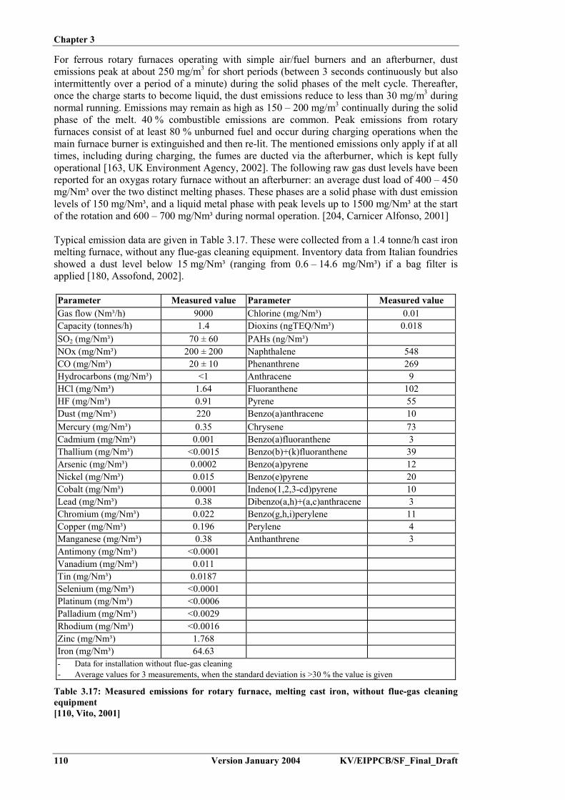
Chapter 3
110 Version January 2004 KV/EIPPCB/SF_Final_Draft
For ferrous rotary furnaces operating with simple air/fuel burners and an afterburner, dustemissions peak at about 250 mg/m3 for short periods (between 3 seconds continuously but alsointermittently over a period of a minute) during the solid phases of the melt cycle. Thereafter,once the charge starts to become liquid, the dust emissions reduce to less than 30 mg/m3 duringnormal running. Emissions may remain as high as 150 – 200 mg/m3 continually during the solidphase of the melt. 40 % combustible emissions are common. Peak emissions from rotaryfurnaces consist of at least 80 % unburned fuel and occur during charging operations when themain furnace burner is extinguished and then re-lit. The mentioned emissions only apply if at alltimes, including during charging, the fumes are ducted via the afterburner, which is kept fullyoperational [163, UK Environment Agency, 2002]. The following raw gas dust levels have beenreported for an oxygas rotary furnace without an afterburner: an average dust load of 400 – 450mg/Nm³ over the two distinct melting phases. These phases are a solid phase with dust emissionlevels of 150 mg/Nm³, and a liquid metal phase with peak levels up to 1500 mg/Nm³ at the startof the rotation and 600 – 700 mg/Nm³ during normal operation. [204, Carnicer Alfonso, 2001]
Typical emission data are given in Table 3.17. These were collected from a 1.4 tonne/h cast ironmelting furnace, without any flue-gas cleaning equipment. Inventory data from Italian foundriesshowed a dust level below 15 mg/Nm³ (ranging from 0.6 – 14.6 mg/Nm³) if a bag filter isapplied [180, Assofond, 2002].
Parameter Measured value Parameter Measured valueGas flow (Nm³/h) 9000 Chlorine (mg/Nm³) 0.01Capacity (tonnes/h) 1.4 Dioxins (ngTEQ/Nm³) 0.018SO2 (mg/Nm³) 70 ± 60 PAHs (ng/Nm³)NOx (mg/Nm³) 200 ± 200 Naphthalene 548CO (mg/Nm³) 20 ± 10 Phenanthrene 269Hydrocarbons (mg/Nm³) <1 Anthracene 9HCl (mg/Nm³) 1.64 Fluoranthene 102HF (mg/Nm³) 0.91 Pyrene 55Dust (mg/Nm³) 220 Benzo(a)anthracene 10Mercury (mg/Nm³) 0.35 Chrysene 73Cadmium (mg/Nm³) 0.001 Benzo(a)fluoranthene 3Thallium (mg/Nm³) <0.0015 Benzo(b)+(k)fluoranthene 39Arsenic (mg/Nm³) 0.0002 Benzo(a)pyrene 12Nickel (mg/Nm³) 0.015 Benzo(e)pyrene 20Cobalt (mg/Nm³) 0.0001 Indeno(1,2,3-cd)pyrene 10Lead (mg/Nm³) 0.38 Dibenzo(a,h)+(a,c)anthracene 3Chromium (mg/Nm³) 0.022 Benzo(g,h,i)perylene 11Copper (mg/Nm³) 0.196 Perylene 4Manganese (mg/Nm³) 0.38 Anthanthrene 3Antimony (mg/Nm³) <0.0001Vanadium (mg/Nm³) 0.011Tin (mg/Nm³) 0.0187Selenium (mg/Nm³) <0.0001Platinum (mg/Nm³) <0.0006Palladium (mg/Nm³) <0.0029Rhodium (mg/Nm³) <0.0016Zinc (mg/Nm³) 1.768Iron (mg/Nm³) 64.63- Data for installation without flue-gas cleaning- Average values for 3 measurements, when the standard deviation is >30 % the value is given
Table 3.17: Measured emissions for rotary furnace, melting cast iron, without flue-gas cleaningequipment[110, Vito, 2001]

Chapter 3
KV/EIPPCB/SF_Final_Draft Version January 2004 111
3.2.6 Argon Oxygen Decarburisation (AOD) converter
Input- molten steel- alloying metals (ferro-alloys)- Al, FeSi, lime- O2, N2, Ar
Output- decarburised steel- metal oxide dust and fumes (Fe,Mn,Cr,Ni)- gases (CO2, CO, inert gases)- slag (CaO,SiO2, AlO3)
3.2.6.1 Input
The AOD converter is used mainly in the production of low carbon stainless steels and, inspecial cases, carbon and low alloy steels: to remove impurities such as carbon, sulphur andoxides and also to decarburise high chromium stainless steels. The processed material is liquidsteel that has been melted in EAF furnaces or in induction furnaces and afterwards poured offinto the vessel through ladles. The technique is most common in the steel industry, but it is alsoapplied in foundries, although to only a limited extent. For decarburisation, oxygen is injected inthe converter and oxidises carbon into CO gas, which escapes from the liquid metal. No energysource is used except for the energy from the combustion reaction between oxygen and carbonduring oxidation and, afterwards, between oxygen and aluminium (and/or silicon) duringreduction.
The consumption of carbon ranges from 0.4 to 1 %, being about 50 – 120 m³ of CO per tonne ofsteel and 25 – 60 m³ oxygen. To eliminate sulphur it is necessary to use a high basicity slag in acompletely reduced liquid steel. Reduction materials, such as aluminium or silicon and lime arecharged in the AOD converter. The consumption levels depend on the quality of the steel gradeand are given in Table 3.18.
Compound Consumption (per tonne of steel)CO 50 – 120 m³O2 25 – 60 m³Al 1 – 2.5 kgLime 10 – 20 kgSi 1 – 2 kgAr 1 – 5 m³
Table 3.18: Consumption levels for the AOD treatment of steel[202, TWG, 2002]
3.2.6.2 Output
Dust emissions are comparable to EAF furnaces’ dusts, both in quantity and quality. AOD dustemissions have lower levels of residuals (organic) from the scrap charge, but on the other handhave a higher level of metal oxide (Cr, Ni), as it is mainly stainless steel which is processed inAOD vessels.
3.2.6.3 Waste gases
The effluent from the mouth of an AOD consists of carbon monoxide and inert gas. The rate ofcarbon monoxide evolution depends on the tuyères oxygen injection rate and the oxygenefficiency, or per cent of oxygen which reacts with carbon. This oxygen efficiency, or “carbonremoval efficiency”, as it is traditionally labelled in AOD operation, varies during the course ofan AOD blow, in response to combined variables of the bath carbon level, temperature, bathchemistry, and the mixture of injected gases.

Chapter 3
112 Version January 2004 KV/EIPPCB/SF_Final_Draft
The CO and inert gas mixture leaves the vessel approximately at the bath temperature. The COmixture exiting the vessel is mixed with excess air in order to fully burn the CO to CO2 veryearly in the exhaust duct. This is done to prevent the presence of combustible or explosivemixtures persisting downstream into the duct to the filter equipment.
3.2.6.4 Slags
Slag is particularly “clean” from metal oxides, since, due to the peculiarity of the process, theyare usually consumed. The slag composition is given in Table 3.19.
Compound %CaO 50 – 70Al2O3 5 – 25SiO2 10 – 25MgO 5 – 15
Table 3.19: AOD slag composition[202, TWG, 2002]
3.2.7 Vacuum Oxygen Decarburisation Converter (VODC)
The VODC process involves decarburisation under reduced pressure. It is much less used thanthe AOD process. Vacuum processes (EAF/vacuum) accounted for 5.8 % of the WesternWorld’s stainless steel production in 1991. The technique consumes 1 Nm³ Ar per tonne ofsteel, shows low chromium oxidation and has a silicon consumption of 3 – 5 kg/tonne. TheVODC allows the production of ultra-low-carbon and nitrogen grades. [202, TWG, 2002]
3.2.8 Steel refining and treatment
For deoxidation, aluminium is commonly used in the form of a stick. Additions vary from 0.1 %for medium carbon steel to 0.2 % for low carbon steel. Recovery is between 35 % and 80 %.Mechanical feeding of aluminium wire is also used. [174, Brown, 2000].
3.2.9 Cast iron treatment
3.2.9.1 Nodularisation
The efficiency, the qualitative assessment of flue-gas production and the complexity of thevarious nodularisation methods are compared in Table 3.20.
Sandwich Tundishcover
Plunging Flowthrough
Wireinjection
Inmold Ductilator
Mg- take-upefficiency (%)
35 – 50 45 – 60 40 – 60 40 – 50 20 – 50 70 – 90 60 – 75
Flue-gasproduction
High Low Low Low Low No High
Comment Easyoperation
Optimisedsandwich butmore mainte-
nance
Highmainte-nance
Highmainte-nance
Expensiveinstallation
Differentdesign ofpouringsystem
Highmainte-nance
Table 3.20: Comparison of various nodularisation procedures[110, Vito, 2001], [225, TWG, 2003]

Chapter 3
KV/EIPPCB/SF_Final_Draft Version January 2004 113
3.3 Melting and the metal treatment of aluminium
3.3.1 Survey of melting furnaces for aluminium
Table 3.21 shows typical furnace properties, consumption and emission data for various types ofaluminium melting furnaces. Due to the wide range of furnace capacities and set-ups, theliterature data does not always provide consistent consumption ranges. Consumption levels arehighly dependent on the furnace capacity and exploitation conditions, such as metal temperatureand charge density.
The use of a pure starting material and mainly electric and gas-fired heating, results in relativelylow emission levels from the melting. Due to the limited concern about off-gas quality,information on the flue-gas composition is limited.
In an aluminium melting operation there is no generation of metal fume and the metal is onlylost when dross forms. This type of loss is often called the loss by burning and is an oxidation ofthe molten metal. It depends on the amount of covering slag and whether combustion occurs. Itis brought about by a leakage of air into the furnace or by the malfunction of the burner. Thecosts for this loss can be high, sometimes even being higher than the energy costs. [148,Eurofine, 2002]
Data for each of the specific furnace types will be discussed and detailed in the subsequentsections.

Chapter 3
114 Version January 2004 KV/EIPPCB/SF_Draft_2
Units Rotary furnace Hearth type furnace Shaft furnace Crucible furnaceSubtype One chamber Fuel heated Resistance heated InductionEnergy sources Fuels (liquid, gaseous) Fuels (liquid, gaseous) Fuels (liquid, gaseous) Fuels (liquid, gaseous) Electricity ElectricityThermal efficiency1 % 15 – 40 <30 – 57 35 – 60 15 – 40 65 65 – 70Primary thermal efficiency2 % 15 – 40 <30 – 57 35 – 60 15 – 40 22 22 – 25Spec. Energy demand3 kWh/t Al4 600 – 1250 975 – 1150 580 – 900
610 – 720900 – 1200610 – 680
750470 – 590
475 – 640440 – 470
Batch/continuous Batch Batch Continuous Batch Batch BatchMelting capacity t 3 – 10 0.5 – 30 0.5 – 4 (-15) 0.1 – 1.2 0.1 – 0.4 0.2 – 25Holding capacity t n.a n.a 1.5 – 10 0.1 – 1.5 0.1 – 1.5 0.15 – 6Meltdown time 2 – 4 3 – 4 0.5 – 1 0.5 – 1 4 – 5 0.2 – 0.5Refining ability Low Low Low Good Very good LowLoss by burning % n.d n.d 1 – 3 1 – 2 1 – 2 1 – 2Dust generation kg/t Al4 n.d <1 <1 <1 Minor MinorNOx 5 kg/t Al4 n.d <1 – 6 <1 – 6 <1 – 6 n.a n.aInvestment costs6 EUR ‘000 n.d n.d 190 – 370 20 – 50 12 – 100 190 – 500Running costs EUR ‘000 n.d n.d 20 – 100 3 – 20 15 – 45 35 – 150Abatement techniques Bag house filter
for bigger installationsBag house filter
for bigger installationsBag house filter
for bigger installationsTypically not necessary
due to small furnace sizeNot necessary Not necessary
1 Definition: the relationship between the heat of the molten bath and the fuel heat supplied; indicated values give an order of magnitude but largely depend on the exploitationconditions, such as the metal temperature
2 Efficiency of electrical power generation (fuels) assumed to be 35 %3 Depends on heat recovery measures; only valid for melting; values given by [148, Eurofine, 2002] in italics4 Units ‘per tonne Al’ refer to tonne of molten aluminium alloy5 Depends on burner design and operational performance6 Depends on heat recovery measures; only valid for meltingSources of information: VDG internal survey; Aluminium Taschenbuch, Band 2, 15. Auflage, Aluminium Verlag GmbH, Düsseldorf, 1996; Aluminium recycling, AluminiumVerlag GmbH, Düsseldorf, 2000; [148, Eurofine, 2002]; comments CTIF
Table 3.21: Typical furnace properties and emission data for aluminium melting[148, Eurofine, 2002] and comments from CTIF and VDG

Chapter 3
KV/EIPPCB/SF_Final_Draft Version January 2004 115
3.3.2 Shaft furnace
Input Output� aluminium ingots, foundry returns� energy� deoxidation and gas removal products
� molten aluminium� dust� NOx, CO� used refractory
Emission factors have been provided for emissions per tonne of good casting, based on thefollowing assumptions:
- average molten metal yield: 70 % (casting/molten metal)- average scrap value: 5 % (scrap from finishing/casting)- global metal yield: 0.7 x 0.95 = 66.5 % (good casting/molten metal)
Consumption and emission data per tonne of good casting for a 3 t/h shaft furnace, meltingaluminium are given in Table 3.22. This also gives the flue-gas emission levels of the rawoff-gas without cleaning.
Input Valueper tonne
Valueper Nm³
Aluminium ingots 1503 kg/tNatural gas 717 kWh/tElectric energy 172 kWh/tTotal energy use 889 kWh/tOutputSlag (with 35 – 40 % Al) 40.3 kg/tUsed refractories 0.3 kg/tEmissions (without flue-gas cleaning)Particles 0.12 kg/t 112 mg/Nm³NOx 0.18 kg/t 113 mg/Nm³VOC 0.12 kg/tSO2 0.04 kg/tCO 150 mg/Nm³Pb + Cr + Cu 0.98 mg/Nm³Cd + Hg 0.01 mg/Nm³As + Ni 0.03 mg/Nm³Data are calculated values per tonne of good casting
Table 3.22: Input and output for aluminium melting in a shaft furnace[177, Silva Ribeiro, 2002]
Table 3.23 gives the consumption levels for a two tonne melting capacity shaft furnacemelting aluminium.
Total measured consumption Specific consumption pertonne of charged metal
Metal charges 115332 kg (54 % ingot, 46 % scrap) 1 tonneMetal tapped 113983 kg 0.988 kg/tonneMetal loss 1349 kg 0.012 kg/tonne – 1.2 %Dross removed 1412 kg 0.012 kg/tonne – 1.2 %Gas consumption 92786 kWh 804 kWh/tonne
Table 3.23: Results from a 6-day trial melt in a 2 tonne melting capacity shaft furnace for Al[48, ETSU, 1994]

Chapter 3
116 Version January 2004 KV/EIPPCB/SF_Final_Draft
3.3.3 Induction furnace
Input Output� aluminium ingots, foundry returns� electrical energy� cooling water
� molten aluminium� dust� used refractory
Aluminium induction furnaces usually range from 500 kg to 2 tonnes capacity and operate atfrequencies of 250 – 1000 Hz.
For example, in one installation, two 1.5 tonne aluminium capacity steel shell tilters arepowered by a 1250 kW, 250 Hz power supply with a change-over switch which allowsalternate furnaces to be melted. With this system 1.5 tonnes can be melted in 40 minutes.
Induction furnaces are energy efficient melters. The energy consumption for melting isaffected by the density of the charge and the melting practice used. Batch melting is lessefficient than using a molten heel. A 50 % molten heel is the most efficient. The energyconsumption varies from 540 kWh/tonne for a high bulk density charge (small scrap andingot) to 600 kWh/tonne if a lower density scrap (such as pressure die-casting runners andingot) is melted. While the energy consumption is low, the costs for melting may be higherthan for gas-fired furnaces because of the generally higher cost of electricity as a source ofheat. [175, Brown, 1999] [148, Eurofine, 2002]
The induction furnace coil needs a cooling system. Cooling water may run in a closed circuitor in an open evaporative system.
3.3.4 Radiant roof furnace (resistance heated)
These resistant heated furnaces are holding furnaces, mainly used for aluminium alloys. Theemission depends on the used metal, the holding-temperature, the surface area and the "metalout" and "metal in" and especially of the holding-time. The emissions are so low that nomeasurements are available. [202, TWG, 2002]
3.3.5 Hearth type furnace
Hearth type (or reverberatory) furnaces exist in various sizes and shapes. Large hearth typefurnaces allow rapid melting and can handle bulky charge material, but the direct contactbetween the flame and charge material may lead to high metal losses, gas pick-up and toconsiderable oxide contamination. Temperature control can also be difficult. This type offurnace is used less because of its relatively low thermal efficiency (around1100 kWh/tonne). The hearth type furnace is also used for copper alloy melting (see Section3.5.1). [175, Brown, 1999]
Table 3.24 gives the emission data for a 450 kg/h oil-fired hearth type furnace meltingaluminium, and working without a flue-gas treatment system.

Chapter 3
KV/EIPPCB/SF_Final_Draft Version January 2004 117
Compound Emission level(mg/Nm³)
Mass flow(g/h)
Yearly mass flow(tonne/yr)
O2 17.6 %CO2 2.2 %CO <4 <24 <0.0438NOx 45 270 0.4928SO2 13 78 0.1424dust 1 6 0.011TOC 5 30 0.0548Al 0.092 0.552 0.001Flue-gas flow: 6000 Nm³/h (dry); operational hours: 1825 h/yr
Table 3.24: Emission data for an oil-fired hearth type furnace melting Al[183, Goovaerts, 2002]
3.3.6 Crucible furnace (fuel and resistance heated)
Input Output� aluminium ingots, foundry returns or liquid
aluminium if used as a holding furnace� electrical energy or fuel
� molten aluminium� dust
Crucible furnaces are indirectly heated using fuel-fired burners or electrical resistors. Forfuel-fired crucibles, the thermal efficiency is not as high as for other melting furnaces, sinceit is difficult to make use of the heat of the combustion products. They are relativelyinexpensive and since the flames are not in contact with the molten metal, metal losses arelow and the melt quality is high, and also alloy changes can be readily carried out. [175,Brown, 1999]
For aluminium alloys the amount of particles can roughly be assumed to be around0.3 kg/tonne of molten metal. [126, Teknologisk, 2000]
Consumption and emission data per tonne of good casting for a 3 t/h crucible furnace,melting aluminium are given in Table 3.25.
InputNatural gas 538 kWh/tonneElectricity 414 kWh/tonneTotal energy input 952 kWh/tonneOutputSlag 61 kg/tonneRefractories 6.87 kg/tonneEmissions (after bag house)NOx 0.18 kg/tonneSO2 0.04 kg/tonneVOC 0.12 kg/tonneDust 0.12 kg/tonneAll data are calculated values per tonne of good casting
Table 3.25: Consumption and emission data for the crucible melting of aluminium[177, Silva Ribeiro, 2002]
3.3.7 Aluminium melt treatment
For the combination of degassing and cleaning in an impeller station, a mixture of argon ornitrogen with 3 % Cl2 is generally used. For degassing alone, the gases Ar or N2 aregenerally used without Cl2. The applied flow and degassing time depend on the type of alloyused and the size of the treatment vessel.

Chapter 3
118 Version January 2004 KV/EIPPCB/SF_Final_Draft
The consumption of modification agents, grain refiners and fluxes depends on the type ofalloy, but is generally in the order of 100 g – 1 kg per 50 kg of molten metal.
3.4 Melting and casting of magnesium and magnesiumalloys
3.4.1 Magnesium melt protection
SF6 and SO2 are used as a covering gas to prevent the oxidation (or burning) of moltenmagnesium. Since SF6 is more easy to handle than the toxic SO2, it became the preferredcover gas after its introduction in the mid 1970s. SF6 has a global warming potential (GWP)of 22200 (for a 100 years time horizon) and an atmospheric lifetime of 3200 years [194,UNEP IPCC, 2002].
The quantities of SF6 used in various operating conditions are given in Table 3.26 (pressuredie-casting) and Table 3.27 (gravity die-casting). These concentrations need to be maintainedclose to the melt surface [191, IMA, et al.]. The tabled values are the recommended practicefor the use of SF6 from the International Magnesium Association (IMA). In practice, higherconcentrations are sometimes used (e.g. 99.4 % CO2, 0.6 % SF6) [202, TWG, 2002].
Melttemp. (°C)
Atmosphere over themelt (vol %)
Surfaceagitation
Residualflux1)
Melt protection
650 – 705 Air/0.04 SF62) No No Excellent
650 – 705 Air/0.2 SF6 Yes No Excellent650 – 705 75 air/25 CO2/0.2 SF6 Yes Yes Excellent705 – 760 50 air/50 CO2/0.3 SF6 Yes No Excellent705 – 760 50 air/50 CO2/0.3 SF6 Yes Yes Very good1) May be present from prior operations2) Minimum concentration under controlled conditionsNote: Dry air (<0.1 % H2O) should be used in the mixing
Table 3.26: The use of SF6 in pressure die-casting operations under various operating conditions[191, IMA, et al.]
Quiescent (melting/holding)low gas flowrate
Agitated (alloying/pouring)high gas flowrate
Cruciblediameter (cm)
SF6 (ml/min) CO2 (l/min) SF6 (ml/min) CO2 (l/min)
30 60 3.5 200 1050 60 3.5 550 3075 90 5 900 50
Note: The suggested flowrates are 1.7 % – 2 % SF6 by volume
Table 3.27: Use of SF6 in gravity die-casting operations[191, IMA, et al.]
To date the only flux-free alternative to SF6 is SO2. In an undisturbed melt, the use would betypically 1 - 2 % in air or nitrogen at a flowrate of 5 to 10 l/min. [182, Closset, 2002], [218,Harnisch and Schwarz, 2003]
In 2001, the overall EU production of magnesium parts totalled 39100 tonnes, 37 % of whichwere produced with SO2 and 63 %, or 24500 tonnes, with SF6 (see Figure 3.4). This issue isdiscussed further in Section 4.2.7.1.

Chapter 3
KV/EIPPCB/SF_Final_Draft Version January 2004 119
0
5000
10000
15000
20000
25000
D E I A F S UK DK P FIN
Mg
die-
cast
ing
prod
uctio
n(M
g to
nnes
per y
ear)
SF6
SO2
EU Member States
Figure 3.4: Mg die-casting production in tonnes/yr by EU states and by cover gas (SO2 or SF6)(data 2001)[218, Harnisch and Schwarz, 2003]
3.4.2 Magnesium melt treatment
Magnesium alloys containing aluminium are treated with hexachloroethane (HCE) for grainrefinement. This treatment applies for alloys for sand and gravity die-casting, which makesup some 10 % of the total magnesium alloys. The required amount of HCE depends on thetype of component to be manufactured and existing data based on the experience of theindividual foundries. An approximate value of 2 kg of HCE per tonne of aluminiumcontaining magnesium alloy has been reported. [178, Wenk, 1995]
3.4.3 Magnesium scrap
In a Mg die-casting foundry, the amount of return materials (Mg- scrap) is nearly equivalentto the amount of good die-castings. About 80 % of the return material complies with scrapgrade class 1 (see Table 3.28).
Class DescriptionClass 1 Clean, compact scrap with known composition
Feeders: cleanPress residues: cleanBad castings: clean, uncoated
Class 2 Scrap castings, painted(partly inserts of Fe, Al, no copper and nickel contamination)
Class 3 Unclean compact metal scrap (oily, wet, contaminated with sand,copper, nickel, ferrosilicon), i.e. mostly post consumer scrap
Class 4 Turnings: clean, dryTurnings: oily, wetScales, flashings, runners: oily, wet
Class 5 Dross (from metal surface)Class 6 Crucible slagClass 7 Flux containing scrap, used salt (black dross)Class 8 Non–metallic residueClass 9 intermetallics
Table 3.28: Magnesium scrap grade classes[206, Ditze and Scharf, 2000]
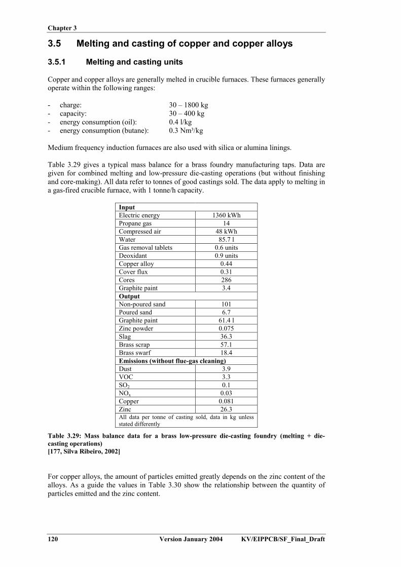
Chapter 3
120 Version January 2004 KV/EIPPCB/SF_Final_Draft
3.5 Melting and casting of copper and copper alloys
3.5.1 Melting and casting units
Copper and copper alloys are generally melted in crucible furnaces. These furnaces generallyoperate within the following ranges:
- charge: 30 – 1800 kg- capacity: 30 – 400 kg- energy consumption (oil): 0.4 l/kg- energy consumption (butane): 0.3 Nm³/kg
Medium frequency induction furnaces are also used with silica or alumina linings.
Table 3.29 gives a typical mass balance for a brass foundry manufacturing taps. Data aregiven for combined melting and low-pressure die-casting operations (but without finishingand core-making). All data refer to tonnes of good castings sold. The data apply to melting ina gas-fired crucible furnace, with 1 tonne/h capacity.
InputElectric energy 1360 kWhPropane gas 14Compressed air 48 kWhWater 85.7 lGas removal tablets 0.6 unitsDeoxidant 0.9 unitsCopper alloy 0.44Cover flux 0.31Cores 286Graphite paint 3.4OutputNon-poured sand 101Poured sand 6.7Graphite paint 61.4 lZinc powder 0.075Slag 36.3Brass scrap 57.1Brass swarf 18.4Emissions (without flue-gas cleaning)Dust 3.9VOC 3.3SO2 0.1NOx 0.03Copper 0.081Zinc 26.3All data per tonne of casting sold, data in kg unlessstated differently
Table 3.29: Mass balance data for a brass low-pressure die-casting foundry (melting + die-casting operations)[177, Silva Ribeiro, 2002]
For copper alloys, the amount of particles emitted greatly depends on the zinc content of thealloys. As a guide the values in Table 3.30 show the relationship between the quantity ofparticles emitted and the zinc content.
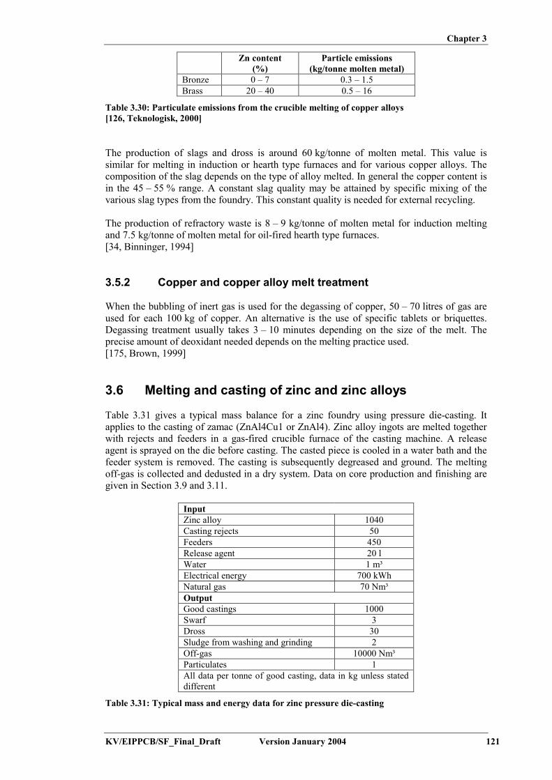
Chapter 3
KV/EIPPCB/SF_Final_Draft Version January 2004 121
Zn content(%)
Particle emissions(kg/tonne molten metal)
Bronze 0 – 7 0.3 – 1.5Brass 20 – 40 0.5 – 16
Table 3.30: Particulate emissions from the crucible melting of copper alloys[126, Teknologisk, 2000]
The production of slags and dross is around 60 kg/tonne of molten metal. This value issimilar for melting in induction or hearth type furnaces and for various copper alloys. Thecomposition of the slag depends on the type of alloy melted. In general the copper content isin the 45 – 55 % range. A constant slag quality may be attained by specific mixing of thevarious slag types from the foundry. This constant quality is needed for external recycling.
The production of refractory waste is 8 – 9 kg/tonne of molten metal for induction meltingand 7.5 kg/tonne of molten metal for oil-fired hearth type furnaces.[34, Binninger, 1994]
3.5.2 Copper and copper alloy melt treatment
When the bubbling of inert gas is used for the degassing of copper, 50 – 70 litres of gas areused for each 100 kg of copper. An alternative is the use of specific tablets or briquettes.Degassing treatment usually takes 3 – 10 minutes depending on the size of the melt. Theprecise amount of deoxidant needed depends on the melting practice used.[175, Brown, 1999]
3.6 Melting and casting of zinc and zinc alloys
Table 3.31 gives a typical mass balance for a zinc foundry using pressure die-casting. Itapplies to the casting of zamac (ZnAl4Cu1 or ZnAl4). Zinc alloy ingots are melted togetherwith rejects and feeders in a gas-fired crucible furnace of the casting machine. A releaseagent is sprayed on the die before casting. The casted piece is cooled in a water bath and thefeeder system is removed. The casting is subsequently degreased and ground. The meltingoff-gas is collected and dedusted in a dry system. Data on core production and finishing aregiven in Section 3.9 and 3.11.
InputZinc alloy 1040Casting rejects 50Feeders 450Release agent 20 lWater 1 m³Electrical energy 700 kWhNatural gas 70 Nm³OutputGood castings 1000Swarf 3Dross 30Sludge from washing and grinding 2Off-gas 10000 Nm³Particulates 1All data per tonne of good casting, data in kg unless stateddifferent
Table 3.31: Typical mass and energy data for zinc pressure die-casting

Chapter 3
122 Version January 2004 KV/EIPPCB/SF_Final_Draft
3.7 Melting and casting of lead
Casting processes for lead may be divided into:- pressure die-casting of lead- casting for storage batteries- sand casting for protective screens.
3.8 Waste gas cleaning
3.8.1 Abatement systems
Various waste and exhaust gas cleaning techniques are used in the foundry industry. Theirprinciples are discussed in the BREF document for non-ferrous metal industries. Theproperties and emission levels of dust abatement systems are given in Table 3.32. A fulldiscussion on the selection of the abatement technique, its applicability in the variousfoundry processes and the achievable emission levels is given as part of the techniques to beconsidered in the selection of BAT in Section 4.5.
Technique ParticleSize
(µm)
CollectionEfficiency
at 1 µm(%)
MaximumOperating
Temperature(°C)
Range ofAchievableEmissions(mg/Nm3)
Comments
Hot EP <0.1 >99Dependingon design
450 5 – 15(Pre abatement
>50)
4 or 5 zones. Usualapplication is pre-abatement
Wet EP 0.01 <99 80 1 – 5(Visually clear)
EP with 2 zones inseries. Mainly mistprecipitation
Cyclone 10 40 1100 100 – 300 Coarse particles.Used to assist othermethods
Fabric Filter 0.01 >99.5 220 1 – 5 Good performancewith suitable dusttype
Wet Scrubber 1 – 3 >80 – 99 Inlet 1000Outlet 80
4 – 50 Good performancewith suitable dusts.Acid gas reduction
EP: Electrostatic precipitator
Table 3.32: Example of current emisions from some dust abatement applications[155, European IPPC Bureau, 2001]
3.8.2 Dioxins
In melting processes, dioxins may be produced if the conditions that give rise to suchpollutants are present at the same location and time in the process. These conditions are:- the presence of chloride ions – these can arise from contaminated scrap, from the use of
coal, coke, fuel oil or from certain fluxes- the presence of organic carbon – this may arise from contaminated scrap and from coal,
coke or oil used as a fuel- temperature conditions between 250 ºC and 450 ºC, with a sufficient gas residence time
in this temperature interval- the presence of a catalyst such as copper- the presence of oxygen.
In evaluating the risk of dioxin formation, a distinction can be made between non-ferrousand ferrous foundries:

Chapter 3
KV/EIPPCB/SF_Final_Draft Version January 2004 123
- Non-ferrous foundries: In as far as when only ingots and internal scrap are melted, therisk of dioxin formation in the melting stage is very low. The melting of pure non-ferrous metals lacks the presence of both the chlorine and carbon required for dioxin(re)formation. However, the re-melting of external non-ferrous scrap materials for metalproduction may involve a risk of dioxin formation. This action, however, falls beyondthe scope of this document and is considered in [155, European IPPC Bureau, 2001]
- Ferrous foundries: Depending on the furnace type and metal load the conditions fordioxin formation could occur. Considering the high temperatures in the melting furnace,dioxin emission (if occurring at all) will mainly generate from de-novo synthesis. Theabove-mentioned conditions can be used to evaluate the risk of dioxin formation.
Dioxin emission data have been gathered from a broad range of sources. Table 3.33 presentsdata for various metals and furnace types. Blank spaces indicate that the indicated numberwas not specified. All systems in the survey do not provide specific dioxin capturetechniques. A distinction can be made between two groups of techniques where dioxin levelsare very low (<0.05 ng/Nm³) or cover a wide range (<0.01 – 3 ng/Nm³). The first groupcovers aluminium melting, the induction melting of iron and the EAF melting of steel. Thesecond group covers cupola melting and the rotary melting of iron. An analysis of theliterature data does not provide a full contribution of the reasons for the differences withinthe second group. However, it can be seen that the presented HBCs with a wet scrubbersystem show noticeably lower PCDD/F emission values.
Product type Furnace Melting Flue-gas Abatement O2 PCDD/F(tonne/h) (m³/h) (%) (ngTEQ/Nm³)
Aluminium Hearth type n.d n.d n.d 0.002Aluminium Hearth type 0.45 9300 None 18.8 0.002Aluminium Shaft 1.5 8400 None 18.4 0.01Cast iron CBC 3.4 15900 Bag filter n.d 0.04Cast iron CBC 3.7 14300 Bag filter 16 0.09Cast iron CBC 4.5 14300 Bag filter n.d 0.09Cast iron CBC 3.4 n.d n.d 0.33Cast iron CBC 5.5 17400 Bag filter 15.9 0.51Cast iron CBC 6.5 17500 Bag filter n.d 0.51Cast iron CBC 6 27600 Bag + PC n.d 3.14Cast iron HBC 45.5 55000 Disintegrator 6 0.003Cast iron HBC 60 n.d Disintegrator n.d 0.003Cast iron HBC 40.6 75000 Bag filter 12.5 0.05Cast iron HBC 50 75000 Bag filter n.d 0.07Cast iron HBC 15 36400 Bag + PC n.d 0.05Cast iron HBC 13 n.d n.d 0.10Cast iron HBC 18.2 29100 Bag filter 8.6 0.20Cast iron HBC 17.1 22500 Bag filter 7.5 0.29Cast iron HBC 27 n.d n.d 1.00Cast iron HBC 28 37000 Bag filter n.d 2.08Cast iron HBC 21 32000 Bag + PC n.d 3.09Cast iron IF 19.5 208000 Bag filter 20.2 0.003Cast iron IF n.d n.d Bag filter n.d 0.01Cast iron RF 8 n.d n.d 0.004Cast iron RF 1.4 9000 None n.d 0.02Cast iron RF 2.1 18600 Bag filter 19.9 0.45Cast iron RF 3.5 n.d Bag filter n.d 0.61
Steel EAF 5.4 54150 Bag filter 20.9 0.003Steel EAF 9 5000 Wet scrubber n.d 0.02
CBC: Cold blast cupola; HBC: hot blast cupola; RF: rotary furnace; IF: induction furnace; EAF: electric arc furnace;
Table 3.33: Dioxin emission data for various foundry types[21, Strauß, 1994], [23, Brettschneider and Vennebusch, 1992], [27, Kran, et al., 1995], [43, Batz,1996], [110, Vito, 2001], [202, TWG, 2002], [225, TWG, 2003], personal communications

Chapter 3
124 Version January 2004 KV/EIPPCB/SF_Final_Draft
The dioxin emission data for the various ferrous metal melting furnaces are discussed below.
- Cupola furnaces: In cupola furnaces, a massive surplus of chlorine is always present fromcoke. Enough carbon is present from coke too, but an additional input of carbon may beneeded the event of caused by poor scrap qualities. Under specific operational conditions, theconditions for dioxin formation could occur. Since de novo synthesis mainly occurs duringcooling of the flue-gas, this applies to both hot blast and cold blast cupolas. In Table 3.34,the result of a statistical analysis of all the measurement data from Table 3.33 for CBC andHBC is given. Whereas Table 3.33 presents average values per plant, for Table 3.34individual measurements were used to perform an overall analysis.
Units Cold blast Hot blastAverage ngTEQ/Nm³ 0.54 0.75St. dev. ngTEQ/Nm³ 1.08 1.3Median ngTEQ/Nm³ 0.18 0.09Minimum ngTEQ/Nm³ 0.001 0.001Maximum ngTEQ/Nm³ 5.1 4.4Number of measurements 35 18Number of furnaces 11 11
Table 3.34: Cupola furnace dioxin emissions[21, Strauß, 1994], [23, Brettschneider and Vennebusch, 1992], [27, Kran, et al., 1995], [43, Batz,1996], [110, Vito, 2001], [202, TWG, 2002], [225, TWG, 2003], personal communications
Data from a German survey (6 installations, 18 measurements) showed a range of0.006 - 0.22 ng TEQ/Nm³, with an average of 0.0724 ng TEQ/Nm³ (0.0608 i-TEQ/Nm³).The data set of the survey partially overlaps with the data set presented above, but it did notgive sufficient information to expand it. [224, Helber, et al., 2000]
The data show that the average, the standard deviation and the range of values are similar forboth cold blast and hot blast furnaces. The median value for hot blast is lower than for coldblast furnaces. This confirms the statement from [224, Helber, et al., 2000] that there is nostatistical difference between dioxin emissions for hot and cold blast cupola furnaces. Thehigh standard deviation shows that the data should be interpreted on a plant-by-plant basisrather than on an averaged basis.
For wet dedusting with a disintegrator, the off-gas passes through the critical temperaturewindow (250 – 450 ºC) after dedusting, i.e. with a low dust content. Additionally, chlorideshave been washed out. This strongly reduces the risk of de novo synthesis.
- Rotary furnaces: Due to the limited possibility of alloying, the rotary furnace chargegenerally consists of clean material. Due to the high flame temperature, the hot gases leavethe furnace at temperatures of between 1000 and 1300 ºC. Post combustion occurs inside thefurnace volume. De novo synthesis is possible if flue-gases cool slowly. Reported data rangefrom 0.004 – 0.61 ngTEQ/Nm³.
- Induction furnaces: Due to the limited possibility of alloying, the induction furnacecharge generally consists of clean material. Furthermore the furnace does not produce aducted high temperature flue-gas stream that cools down slowly.
- Electric arc furnaces: EAF furnaces allow melt treatment and alloying if operated inbasic lining practice. This enables the use of dirty scrap as a raw material for melting. Ifscrap containing organic and/or chlorinated compounds is charged, dioxins may be formedduring cooling of the flue-gas stream. This may be the case when using scrap from e.g.electronic equipment, transformers, and shredded vehicles. The EAF in acid lining practicedoes not allow metal treatment and therefore the possibility for feeding contaminated scrap isreduced. This also reduces the risk of dioxin formation.
[161, UK Environment Agency, 2002]

Chapter 3
KV/EIPPCB/SF_Final_Draft Version January 2004 125
3.9 Mould and core production
3.9.1 Introduction
Mould and core production involves mixing sand with various chemicals, in some casesfollowed by a heating step. Gaseous or volatile reaction-products and excess reagents areemitted. Table 3.35 presents a survey of the emissions and other environmental impactsduring the mixing, setting and storage of the moulds and cores. A further discussion of theemission and consumption levels for each of the binder types is given in the subsequentsections.
System name and binderconstituents
Setting method andrelative energy
requirement
Emissions to airduring mixing and
setting
Other environmental impacts
GREEN SANDClayCoal dust or substituteWater
Pressure – low Particulate matter –no significantemission to theenvironment
Sand spillage around conveyors needsto be avoided to reduce the likelihoodof fugitive emissions.Abatement from the mixing process isnot essential (the process is usuallyself-contained with displaced airvented to the foundry)
SHELL SANDPhenol - formaldehyde(Novalak) Resin
Heat - high Formaldehyde*Ammonia*Phenol*AromaticsHCN
Odour can be an issue as the shellmachines are normally extracted to air
ALKALINE PHENOLICResol - Alkaline phenol-formaldehyde resin
1. Gas hardened(alkaline phenolic cold-box)
2. Self-setting(alkaline phenolic no bake)
Gas hardened with methylformate vapour – low
Cold-set with esters - low
Formaldehyde*Phenol*Methyl formate
Formaldehyde*Phenol*Esters
PHENOLICURETHANE1. Gas hardened: Cold-box
2. Self-setting(phenolic urethane nobake)
Amine vapour – low
Self-set with substitutedpyridine – low
Isocyanate (MDI)Amine*Formaldehyde*Phenol
Isocyanates (MDI)Formaldehyde*Phenol
Odour is frequently a problem – whereDMEA is used odours arise andabatement is essential. This may beincineration or gas scrubbing (usingsulphuric or phosphoric acids) – thelatter gives rise to liquors, which are aspecial waste.Where TEA is used scrubbing is onlyrequired if odour problems arise
FURANCombination resins of:PhenolUreaFurfuryl alcoholFormaldehyde
Cold-set with acids – low Formaldehyde*Phenol*Furfuryl alcohol*Hydrogen sulphideAcid mists
Resins and acids must be kept apart(unless sand is present) as they arevigorously exothermic when in contact
HOT-BOXCombination resins of:PhenolUreaFurfuryl alcoholFormaldehyde
Heat – high Formaldehyde*AcidsFurfuryl alcohol*Phenol*AmmoniaIsocyanic acidMethyl isocyanate
Odour can be an issue as the shellmachines are normally extracted to air

Chapter 3
126 Version January 2004 KV/EIPPCB/SF_Final_Draft
System name and binderconstituents
Setting method andrelative energy
requirement
Emissions to airduring mixing and
setting
Other environmental impacts
OIL SANDLinseed oil and starch Heat – high
Acrolein*Complex organics
Odour can be an issue as the coreovens are often extracted to air
CO2 PROCESSSodium silicate Gas hardened with CO2
gas – lowNone
SILICATE ESTERSodium silicate Cold-set with esters – low EstersNote 1: All the above processes give rise to spent sand (including broken cores, spillage and mixer residues) that may go to landfillNote 2: Substances marked with * are those most likely to give rise to odour from the process referred toNote 3: Any resin binder component would be regarded as special waste for disposal purposes and if spilled could give rise to a risk
of contamination of water systemsNote 4: Amines and methyl formates used for gas hardening are highly flammable and odorous. The avoidance of leaks in storage is
essential
Table 3.35: Environmental impact from binder systems[126, Teknologisk, 2000], [160, UK Environment Agency, 2002], [225, TWG, 2003], [229, Lilja,et al., 2000]
Quantitative data for dust emissions from moulding shops have been gathered in an Italianfoundry survey. The results are given in Table 3.36. All exhaust cleaning systems attain alevel <15 mg/Nm³.
Concentration (mg/Nm³) Emission factor (g/tonne)*Average Minimum Maximum Average Minimum Maximum
Bag filter 3.2 0.4 12.1 24.4 0.5 108.3Wet scrubber 5.2 3.6 6.7 6.2 4.0 8.0Wet Venturi system 9.6 8.5 10.9 34.2 30.1 39.9Units: g/tonne of good castingNumber of data points: bag filter: 33; wet scrubber: 4; wet venturi system: 3
Table 3.36: Emission values and emission factors for dust emissions from moulding shops afterexhaust cleaning[180, Assofond, 2002]
The emissions given in Table 3.35 refer to the stages of mixing, setting and storage of themoulds and cores. Most emissions persist during the metal pouring and casting cooling stages,but now with the addition of pyrolysis products. These will be discussed in Section 3.10.1.
Table 3.37 gives dust emission data from a German measurement campaign. The dust wasanalysed into PM10, PM2.5 and PM1 fractions.
Activity Off-gasvolume(Nm³/h)
Gas cleaningequipment
Total dust(mg/m²)
PM10(%)
PM2.5(%)
PM1(%)
Sandpreparation
25600 Bag filter 0.3
Green sandpreparation
24400 Fume hood,bag filter
0.7 88 38
Sandpreparation
70400 ESP 22 – 28.3 79 18
Core shop 4670 (dry) Aminewasher
0.7 98 47 – 62
Mouldingshop
52300 (dry) Bag filter 0.7 95 – 97 50 – 60 2 – 5
Finishing 22000 (dry) Bag filter 5.3 100 45 – 48 9
Table 3.37: Example dust emissions and particle size for mould and core-making[202, TWG, 2002]

Chapter 3
KV/EIPPCB/SF_Final_Draft Version January 2004 127
3.9.2 Moulding with clay-bonded sand (green sand moulding)
Input Output� sand� bonding clay (e.g. bentonite)� coal dust, dextrin� water (to prepare moulding mix)
� green sand moulds� dust (silica fines, partially burnt-out
clay, unburned coal dust and ash)
The composition of the bentonite added to the sand depends on the specific properties ofboth the sand and the bentonite, as well as on the desired strength and gas permeability of thefinished mould. Table 3.38 gives some parameters of clay-bonded sand, as obtained from aselection of 105 sand samples taken from iron foundries.
Parameter Units Average % of samples in range ofaverage ���� 10 %
Maximumvalue
Minimumvalue
Range %Water content % 4.1 3.4 – 4.5 48 6.9 2.4Bentonite content % 8.3 7.5 – 9.1 45 11.9 5.6Density g/cm³ 0.940 1.00 – 0.85 75 1.06 0.73Loss on ignition % 5.0 4.5 – 5.5 20 15.0 1.0Compressivestrength
N/cm² 18.6 16.7 – 20.5 54 24.5 13.2
Table 3.38: Typical properties of green sand, measured on 105 sand samples from 105 ironfoundries[36, Winterhalter, et al., 1992]
Further additives are mixed in the green sand mixture:- Coal dust: Used mainly in iron foundries, but also to a lesser degree in some non-ferrous
foundries. Coal dust levels in green sand vary from 2 or 3 % for small castings, to 7 or8 % for heavy section castings. Too much coal dust can give rise to holes in the castingsor in misruns. Various coal dust replacement products exist. They are generally added ina slightly altered concentration compared to the coal dust
- Cereal binders: Starch and dextrin are used mainly in steel foundries to avoid defectscaused by silica expansion and to control moisture excess in the sand mix. Effectiveadditions of cereal binders to new green sand facing mixes are between 0.5 and 0.75 %.In unit type green sands, part of the cereal is destroyed during the casting process. Therecommended addition on each recycle is 0.1 to 0.25 %, depending on the amount ofcereal burn-out and on the dilution by cores and new sand.
[174, Brown, 2000], [225, TWG, 2003]
3.9.3 Moulding with unbonded sand (V-process)
Input Output� dry sand� PE sheets� energy (produce and maintain vacuum)
� moulds� dust
The thermal shock induced by the contact of the molten metal breaks up the sand grains,generating dust that is mostly emitted during shake-out. The remaining dust in the sand hasto be removed in order to allow the re-use of the sand for moulding. Using this method, onlya small amount of dust should occur during the filling of the moulding boxes.

Chapter 3
128 Version January 2004 KV/EIPPCB/SF_Final_Draft
This process is of interest because of its very low environmental impact. However, as itsprocess cycle involves many steps, the moulding rate is low and the gap between startingtimes for each new different casting is lengthy. Moreover investment costs are very high. Asa consequence, this process has found only limited application.
3.9.4 Moulding and core-making with chemically-bonded sand
Input Output� sand� resin� catalyst, hardener, additives
� sand moulds and cores� excess reagents� reaction products� dust
3.9.4.1 Chemicals consumption levels
The consumption levels of the various types of binders, hardeners, catalysts and additives aregiven in Table 3.39.
Hardeningtype
Resin type Resinaddition
% on sandweight
Catalyst/hardener
type
Catalyst/hardeneraddition
% on resinweight
Additivetype
AdditiveAddition
% on sandweight
Cold-setting Furan 0.8 – 1.5 Sulphonic acid 25 – 60 Silane 0.1 – 0.2Phenolic 1 – 2 Sulphonic acid 25 – 50 n.a n.a
Polyurethane 0.8 – 1.5 Pyridine derivate 2 – 6 n.a n.aResol 1.0 – 1.5 Ester 22 – 25 n.a n.a
Alkyd oil 1.0 – 2.0 Isocyanate 18 – 20 Catalyst 0.002 – 0.2Ester silicate 2.0 – 4.5 Ester 10 – 15 n.a n.a
Hardeningtype
Resin type Resinaddition
% on sandweight
Catalyst type Catalystaddition
% on sandweight
Additivetype
AdditiveAddition
% on sandweight
Gas hardening Phenolic/Furan 0.8 – 1.2 SO2 0.3 – 3 Peroxide 0.1 – 0.5Polyurethane
Cold-box1.0 – 1.8 Amine 0.05 – 0.15 n.a n.a
Resol 1.2 – 1.8 Methyl fomate 0.3 – 0.5 n.a n.aResol 2 – 2.5 CO2 0.7 – 1.25 n.a n.a
Acryl/Epoxy 1.2 – 1.6 SO2 0.02 – 0.05 Peroxide 0.05 – 0.06Silicate 2 – 4 CO2 1 – 2 n.a n.a
Hardeningtype
Resin type Resinaddition
% on sandweight
Catalyst type Catalystaddition
% on resinweight
Additivetype
AdditiveAddition
% on sandweight
Thermosetting Oil 0.8 – 4 n.a n.aWarm-box
furfurylalcohol-based
1.0 – 1.5 Cu salts ofsulphonic acids
10 – 30 n.a n.a
Hot-boxphenolic orfuran based
1.2 – 3.0 Ammonium salts 10 – 25 n.a n.a
Croningphenolic
1.5 – 5 Hexamethylene-tetramine
15 n.a n.a
Table 3.39: Consumption levels of various resins, catalysts, hardeners and additives forchemically-bonded sand preparation[174, Brown, 2000], [225, TWG, 2003]

Chapter 3
KV/EIPPCB/SF_Final_Draft Version January 2004 129
3.9.4.2 Emission factors
The use of chemical binders results in the production of various compounds during mixing,mould- and core-making, storage, pouring and cooling, as indicated in Table 3.35. Someindicative emission factors for several processes are given in Table 3.40 and Table 3.41.
Furan sand Phenolic sandOrganic solvents 1.4 1.25Phenol 0.02 0.18Formaldehyde 0.08 0.15All data in kg/tonne molten metal
Table 3.40: Emission factors for mould making[110, Vito, 2001]
Cold-box Hot-box ShellDust n.a 0.003 0.003Furfuryl alcohol 0.1 n.a n.aFormaldehyde 0.01 n.a 0.003Organic solvents n.a 0.03 n.aAromatic solvents 0.12 n.a n.aAmines 0.13 n.a n.aAll data in kg/tonne molten metaln.a: not applicabble
Table 3.41: Emission factors for core-making[110, Vito, 2001]
3.9.4.3 Cold-setting processes emissions
Emissions for the cold-setting processes can be described as follows:
- Phenolic: Vapours of formaldehyde and phenol may be emitted because of the vapourpressure of these constituents. But, as the polymerisation occurs at ambient temperature,these vapour pressures are low and given the consumption rates, the emissions areinsignificant
- Furan: Vapours of formaldehyde, phenol, furfuryl alcohol and alcohols may be emittedbecause of the vapour pressure of these constituents. But, as the polymerisation occurs atambient temperature, these vapour pressures are low and given the consumption rates,the emissions are insignificant
- Polyurethane: Vapours of formaldehyde, phenol, isocyanate and aromatic solvents maybe emitted because of the vapour pressure of these constituents. As the polymerisationoccurs at ambient temperature, the vapour pressures of the components are low andgiven the consumption rates, the emissions are insignificant. Obnoxious odours may begenerated in the moulding area but are not likely to cause external nuisance
- Resol-ester: The resin contains unreacted phenol and formaldehyde, but their emissionsare extremely low and environmentally insignificant
- Alkyd-oil: During production of the moulds and cores, there are no emission problems,unless they are cured by heat, in which case odour problems may occur
- Ester silicate: This process does not generate any emission problems.[32, CAEF, 1997]

Chapter 3
130 Version January 2004 KV/EIPPCB/SF_Final_Draft
3.9.4.4 Gas-hardened processes emissions
Emissions for the gas-hardened processes can be described as follows:
- Cold-box: Vapours of formaldehyde, phenol, isocyanate and aromatic solvents areemitted in low quantities, in spite of their low vapour pressures. Aromatic solventemissions are highest during purging. The most significant emission is that of amines,which have low odour detection thresholds and can create an external nuisance. Aminesare hazardous, with a relatively low exposure value limit, and possess a strongcharacteristic smell at very low concentrations
- Resol-ester: The resin contains unreacted phenol and formaldehyde, but their emissionlevels, even during the gassing and purging periods, are very low. Methyl formate is nottoxic, does not have an unpleasant smell and its exposure value limit is relatively high
- Resol-CO2: The resin has low contents of unreacted phenol and formaldehyde, and theiremission levels, even during the gassing and purging periods, are very low
- SO2 hardened phenolic and furan resin: The resins and the prepared sands generateformaldehyde emissions. The major emission problem is caused by sulphur dioxide,which is very hazardous
- SO2 hardened epoxy/acrylic: Minimal emissions are generated during the core-makingprocess
- CO2 silicate: This process does not generate any emission problems during moulding orcore-making.
[32, CAEF, 1997]
3.9.4.5 Hot curing processes emissions
Emissions for the hot curing processes can be described as follows:
- Hot-box emissions: The patterns are generally heated by open air gas burners, producingcombustion gas emissions. The off-gas may contain phenol, ammonia, formaldehyde andmonoisocyanates (if the resin contains nitrogen)
- Warm-box emissions: Compared to the hot-box process, the emissions are significantlylower. The emissions do not contain phenol or ammonia, and also formaldehydeemissions are diminished by a factor of 4. As the pattern temperature is also lowercompared to the one used for the hot-box process, the working conditions are alsoimproved. The environmental impact is considered to be relatively low
- Shell emissions: Compared to the hot-box process, cured sand consumption is very low.However, the pre-coated sand contains 2 to 3 times more resin, but as the patterntemperatures are approximately the same, the resulting impact on working conditions issimilar.
- Linseed oil emissions: As the oils are often in solution in organic solvents such asnaphtha or kerosene, a large amount of VOC is generated by curing, which may result inan external odour nuisance. This problem is even more persistent during pouring. Theseproblems, as well as poor productivity, are some of the reasons for the reduction ininterest in the use of this process.
[32, CAEF, 1997]
A mass balance for a hot-box core shop is given in Table 3.42. Data were collected from acore shop of a low-pressure die-casting brass foundry [177, Silva Ribeiro, 2002].

Chapter 3
KV/EIPPCB/SF_Final_Draft Version January 2004 131
InputNew sand 371Electric energy 352.9 kWhPropane gas 7Compressed air 187.1 kWhResin 8.3Conservative 0.51Catalyst 0.76Coating 1.7OutputCores 287.7Sand not poured 84.3Resin 1.4 lMetallic and plastic containersEmissions (after bag filter)Particulate emissions 0.11VOCs 0.83All data are per tonne of castings sold, values in kg unless stateddifferently
Table 3.42: Mass balance data for brass foundry core using a hot-box process[177, Silva Ribeiro, 2002]
3.9.5 Coating of chemically-bonded sand moulds and cores
Input Output� coatings ready to use or mass to be diluted
with water or alcohol� heat for solvent evaporation
� VOC (alcohol-based)
3.9.6 Expendable pattern casting (Lost Foam/full mould casting)
3.9.6.1 Unbonded sand – Lost Foam
Input Output� EPS granulate� EPS glue� refractory coating� sand
� sand moulds� EPS residues� products of pyrolysis and combustion� dust
In producing aluminium castings, around 15 kg/tonne good casting of EPS granulate isconsumed. Refractory coating consumption is around 20 kg/tonne good casting.
Table 3.43 shows a comparative analysis of a green sand and a Lost Foam aluminiumfoundry, both producing 5490 tonnes of good castings per year. It should be noted that thevalues do not take into account the internal regeneration. In practice, both types of foundrywill apply regeneration, thus reducing the amount of residue effectively left for disposal.
Residue type Lost Foam foundry Green sand foundryFoundry sand (without internal regeneration) 1.04 2.95Filter dust (without internal regeneration) 0.056 0.22Filter dust (with internal regeneration) 0.056 0.61EPS residue 0.0027 -All values in kg/tonne good casting
Table 3.43: Comparative data for residue production from Lost Foam and green sandaluminium casting[96, Spillner, 1997]

Chapter 3
132 Version January 2004 KV/EIPPCB/SF_Final_Draft
Emission data for organic compounds are given in Table 3.44. These apply to an aluminiumLost Foam foundry producing 1.5 tonne/h compared to a green sand foundry producing1.2 tonne/h and using 1.9 tonne/h cold-box cores. The Lost Foam foundry was equipped witha bag house and a post combustion unit. The green sand data apply to a unit with bag housefiltration. The data show that the Lost Foam foundry, with the application of more intenseflue-gas cleaning, emits higher levels of BTEX and formaldehyde, but a clearly lower levelof organic carbon. Post combustion of the casting off-gases is needed to decompose theproducts from EPS pyrolysis upon pouring.
Compound Lost Foam foundry Green sand foundryBenzene 35.33 8.5Toluene, xylene, ethylbenzene, styrene 354.67 18.58Unknown organic compounds 96.67 655.0Total organic carbon 857.33 1283.33PAH 1.45 1.43Formaldehyde 18.00 2.08Phenol 18.00 69.83All values in g/tonne molten aluminium
Table 3.44: Stack emission data for Lost Foam and green sand aluminium foundries[96, Spillner, 1997]
3.9.6.2 Chemically-bonded sand – full mould
Input Output� EPS granulate� EPS glue� refractory coating� sand� binders
� sand moulds� EPS residues� products of pyrolysis and combustion� dust
The mass flow of emissions from full mould and hollow mould casting processes are to beconsidered as similar. This can be seen from Figure 3.5 which shows the mass flow oforganic carbon as a function of time upon pouring. Time ‘0:00’ corresponds to the starting ofthe pouring. The data were collected using furan-bonded sands, both for full and hollowmould making.
The full mould process shows a high emission upon pouring and an initial peak emissionimmediately after pouring which levels off within 1 hour. The hollow mould process shows alower initial emission, but the levelling off goes slower and takes up to 2 hours. Therefore,the total organic carbon emission over the whole cooling step is equal for both processes.Additional measurements showed that the same profile applies for benzene, ethyl benzene,phenol and furfuryl alcohol. The maximum emission for styrene and toluene occurs after15 – 30 minutes. This is due to an initial condensation of the molecules on the colder parts ofthe mould. [215, Müller, 1996]

Chapter 3
KV/EIPPCB/SF_Final_Draft Version January 2004 133
Figure 3.5: Waste gas load upon pouring in full and hollow mouldscast alloy: lamellar iron; mould: furan bonded sand; 1.9 tonne sand: 1 tonne Fe[215, Müller, 1996]
3.10 Casting
3.10.1 Casting, cooling and shake-out, using lost moulds
3.10.1.1 Emission levels
Input Output� finished moulds� molten metal
� castings� used sand� combustion products (from preheating of pouring
ladles)� organic pollutants from pyrolysis and thermal
degradation of binder, blackening moulds, etc.(phenol, formaldehyde, amine, hydrogen cyanide,PAH, benzene, VOC)
� odour� waste from exhaust air cleaning (dry/sludge)� dust from shake-out
Whilst preheating ladles, combustion gases are generated as a result of using natural gas asthe common energy source.
The following emission types can occur during pouring:- thermally degradable components, such as exothermic sleeves, react releasing fumes
and/or vapours- chemical compounds from the binder and some blacking systems which can be released
as a result of thermal degradation and/or volatilisation, e.g. combustion gases, watervapour, and volatile organic compounds. Some of the degradation products can beodorous.
Experience shows that the maximum emissions (related to total-C) only occur 10 minutes ormore after pouring. CO is the main component, with the level of CO being indicative of therelease of other compounds. [110, Vito, 2001]

Chapter 3
134 Version January 2004 KV/EIPPCB/SF_Final_Draft
During cooling and shake-out, the thermal decomposition processes proceed and volatilecompounds are generated, mainly controlled by diffusion and evaporation rates.The removal (shake-out) of the sand moulds and cores from castings is a dust-intensiveprocedure, as the moulds, at least partially, have to be crushed.
The second cooling step releases nothing except water vapour from those plants, wherewater spray is used as a cooling aid. [32, CAEF, 1997]
The type of emissions during casting are dependent on the binder type used. Emissions arecomparable to those during the mixing stage, with the addition of pyrolysis productsoccurring upon contact with the hot metal. Table 3.45 gives the results from a qualitativesurvey of the emissions associated with the various binder types.
System name and binderconstituents
Emissions to air during casting Comments
GREEN SANDClayCoal dust or substituteWater
Particulate matter- soot from coalburningCarbon monoxide and carbondioxideBenzeneTolueneXylene
Potential odour (may beassociated with the sulphurcontent of the coal)
SHELL SANDPhenol - Formaldehyde(Novalak) Resin
Particulate matter – soot from theincomplete combustion of carbonbased resinsCarbon oxidesPhenol*, cresols* and xylenols*AmmoniaAldehydesBenzenePAH
Odour problems more prevalent– treatment may be necessaryalthough dispersion may suffice
ALKALINE PHENOLICResol - Alkaline phenolFormaldehyde resin
1. Gas hardened
2. Self-setting
Particulate matter – soot from theincomplete combustion of carbonbased resinsCarbon oxidesFormaldehydePhenol, cresols and xylenolsAromatics
Odour may be a problem
PHENOLIC URETHANE1. Gas hardened e.g. Cold-box
2. Self-setting(phenolic urethane no bake)
Particulate matter – soot from theincomplete combustion of thecarbon based resinsCarbon oxidesNitrogen oxidesMonoisocyanatesFormaldehydePhenol, cresols and xylenolsAromatics (inc. polycyclics)AnilinesNaphthalenesAmmonia
Odour may be a problem

Chapter 3
KV/EIPPCB/SF_Final_Draft Version January 2004 135
System name and binderconstituents
Emissions to air during casting Comments
FURANCombination resins of:PhenolUreaFurfuryl alcoholFormaldehyde
Particulate matter – soot from theincomplete combustion of thecarbon based resinsCarbon oxidesPhenol, cresols and xylenolsFormaldehydeAromatics (inc. polycyclics)Sulphur dioxideAmmoniaAnilineIsocyanic acid*Methyl isocyanate*
Odour may occasionally be aproblem
HOT-BOXCombination resins of:PhenolUreaFurfuryl alcoholFormaldehyde
Particulate matter – soot from theincomplete combustion of carbonbased resinsCarbon oxidesNitrogen oxidesFormaldehydePhenol, cresols and xylenolsAromatics (inc. polycyclics)AnilineAmmoniaIsocyanic acid*Methyl isocyanate*
OIL SANDLinseed oil and starch
Particulate matter – soot from theincomplete combustion of carbonbased resinsCarbon oxidesButadieneKetonesAcrolein
Odour may be a problem
CO2 PROCESSSodium silicate Carbon oxides
SILICATE ESTERSodium silicate Carbon oxides
AlkanesAcetoneAcetic acidAcrolein
* For resin containing nitrogen (urea)
Table 3.45: Environmental impact from binder systems upon pouring, shake-out and cooling[160, UK Environment Agency, 2002]
Emission factors for iron casting in cold-setting sand moulds as used in Belgium are given inTable 3.46.
Compound Average kg/tonne meltedCO 1.1Aliphatic heterocyclic hydrocarbons 0.22Aromatic hydrocarbons 0.05HCN 0.03Formaldehyde 0.02Sulphur compounds (when using paratoluene sulphonic acid) 0.10Volatile organophosphorous compounds (when using phosphoric acid) 0.11
Table 3.46: Emission factors for iron casting in cold-setting resin-bonded sand moulds[110, Vito, 2001]

Chapter 3
136 Version January 2004 KV/EIPPCB/SF_Final_Draft
The emission factors during pouring, cooling and shake-out for a mixed sand system, havebeen determined through an intensive measurement programme in two automotive foundriesin Mexico. The foundries under study produced iron castings, using green sand moulds andchemically-bonded sand cores. The emission factors are very process-specific and varyaccording to changes in the mould or core composition, or changes in the process parameterssuch as cooling time, or in the techniques applied, such as the type of shake-out deviceapplied. Nevertheless, the emission factors obtained provide useful information on the typeof emissions and on the relative importance of the various process steps. The emissionfactors for the most important detected air pollutants are presented in Figure 3.6. The datashow that the highest emissions occur during shake-out and only minor emission occurduring pouring. Naphthalene and monomethylated naphthalenes mainly contribute to thePAH emission. Further analysis of this category revealed that many of the carcinogenicPAHs, such as benzo(a)pyrene were not detected.
The major metal emissions include manganese, lead, nickel, copper and chromium, with leadand manganese being greatest. [141, CERP, 1999]
Figure 3.6: Emission levels of pollutants upon pouring, cooling and shake-out for a green sandiron foundry[141, CERP, 1999]
Emission factors for particulate matter are displayed in Figure 3.7. These are based onmeasurements of total dust, PM10 (particles less than or equal to 10µm) and PM2.5 (particlesless than or equal to 2.5µm). Note that by definition PM10 includes PM2.5. [141, CERP, 1999]

Chapter 3
KV/EIPPCB/SF_Final_Draft Version January 2004 137
Figure 3.7: Emission levels for particulate matter upon pouring, cooling and shake-out for agreen sand iron foundry(Total = PM10 + PM>10)[141, CERP, 1999]
Data in the above figures apply to raw gas. In an Italian sector survey, emission data forcleaned exhaust flows were collected and are given in Table 3.47 [180, Assofond, 2002]. Allexhaust cleaning types reach a dust emission level of <20 mg/Nm³. Wet scrubbers show thebest performance, though it should be noted that the data are based on only threemeasurements.
Flue-gas cleaning Concentration (mg/Nm³) Emission factor (g/tonne)*equipment Average Minimum Maximum Average Minimum MaximumBag filter 5.8 1.0 16.8 68.5 7.8 206.9Wet scrubber 2.3 1.8 2.8 16.3 13.3 18.0Wet multicyclone 18.6 14.6 21.9 202.2 163.6 224.4Wet Venturi system 11.7 6.2 16.9 116.3 38.2 187.7* Emission factor in g/tonne of good casting
Table 3.47: Emission values and emission factors for dust emission from shake-out after flue-gascleaning[180, Assofond, 2002]
3.10.1.2 Sand-to-liquid metal ratios
Excessive amounts of sand in the moulding system results in unnecessary capital andoperating costs. A lower sand-to-liquid metal ratio will reduce the total volume of sand in thesystem and, therefore, reduce the consumption of new materials.
The distribution of sand-to-liquid metal ratios for green sand in the iron sector is shown inFigure 3.8. Data were collected from a survey of the UK foundry sector. While the averagesand-to-liquid metal ratio in this sector is 9:1, some foundries are operating eitherconsiderably above or below this figure. The lower ratios are generally associated withcertain types of metal moulds or single-product foundries where box size/castingcombinations are more easily optimised. The higher ratios are generally caused either by
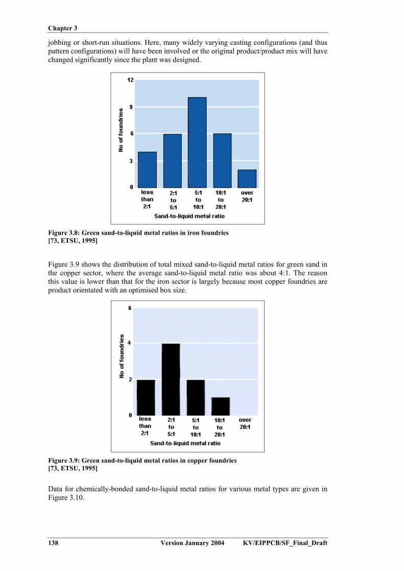
Chapter 3
138 Version January 2004 KV/EIPPCB/SF_Final_Draft
jobbing or short-run situations. Here, many widely varying casting configurations (and thuspattern configurations) will have been involved or the original product/product mix will havechanged significantly since the plant was designed.
Figure 3.8: Green sand-to-liquid metal ratios in iron foundries[73, ETSU, 1995]
Figure 3.9 shows the distribution of total mixed sand-to-liquid metal ratios for green sand inthe copper sector, where the average sand-to-liquid metal ratio was about 4:1. The reasonthis value is lower than that for the iron sector is largely because most copper foundries areproduct orientated with an optimised box size.
Figure 3.9: Green sand-to-liquid metal ratios in copper foundries[73, ETSU, 1995]
Data for chemically-bonded sand-to-liquid metal ratios for various metal types are given inFigure 3.10.

Chapter 3
KV/EIPPCB/SF_Final_Draft Version January 2004 139
Figure 3.10: Total mixed sand-to-liquid metal ratios in UK foundries[72, ETSU, 1995]
3.10.1.3 Metal yield
The metal yield is the ratio of the amount of metal melted to the weight of the finished goodcastings. Five main factors affect metal yield, i.e.:- quality requirement- choice of mould-box size- the extent of runner and feeder systems- metal shrinkage- scrap casting rate.
Metal yield does not have a direct effect on sand use. However, an increase in yield mayresult in fewer moulds being produced, which means that less sand is consumed overall.Lower metal yields are generally associated with higher integrity products, where superiorquality standards may be required, necessitating a more extensive feeding system. Loweryields, however, may also be indicative of higher scrap rates and excessive feeding systems.In these circumstances, foundries need to review their process control and mould productionmethods. The average metal yields for the main alloy sectors are given in Table 3.48.

Chapter 3
140 Version January 2004 KV/EIPPCB/SF_Final_Draft
Sector Average metal yield(%)
Range of yields reported(%)
Lamellar iron 68 40 – 90Nodular iron 63 40 – 90Aluminium 57 40 – 80Copper 58 30 – 90Steel 45 n.d
Table 3.48: Metal yield in the main alloy sectors[73, ETSU, 1995], [225, TWG, 2003]
Data were collected through a survey in the UK foundry sector and from the Portuguesefoundry association (the latter for steel). A significant number of survey respondentsdeclined to supply yield data, particularly in the aluminium and copper sectors. However,some general comments on metal yield can be made:- the range of yields reported for lamellar iron and nodular iron was from 40 % to over
90 %- metal yields reported by aluminium foundries were fairly evenly distributed between
40 % and 80 %. Over 50 % of aluminium foundries, however, chose not to supply data- half the small number of copper foundries that supplied data are achieving yields of
between 50 % and 60 %, though the reported range is 30 % to over 90 %.[73, ETSU, 1995]
3.10.1.4 Used foundry sand
A review and study of foundry waste sand quality and composition was performed inFinland. Data were collected from literature and from own experiments [169, Orkas, 2001].
In several studies, chemical analyses on used foundry sands from various sources wereperformed. A summary of the most significant results is presented in Table 3.49. The datashow that the contents of metallic and organic harmful compounds in used foundry sand arenormally low. Generally, the contents of organic and metallic harmful compounds are higherin green sands compared to chemically-bonded sands. Inorganic sands are basically veryclean.
Compound Greensand
(mg/kg)
Organicsand
(mg/kg)
Inorganicsand
(mg/kg)Ba 35 – 118 2.4 –5.5 n.dCr 1.7 –13.5 1.2 –7.2 <5Fe 2950 – 21000 640 – 16300 530 – 1700Zn 1.5 – 1450 1.6 – 49 <10 – 30.0Cd 0.03 – 6.7 0.01 – 0.03 0.02Pb 1.6 – 390 0.4 – 2.1 1.3Cu 4.7 – 5.0 2.7 – 4.4 <1.5 – 6.0Ni <2.5 – 20.0 0.3 – 8.5 2.5 – 8.3Mn 76 – 78 22 – 79 25 – 34As 0.2 – 2.1 0.2 – 1.8 <0.5 – 0.51Phenol 1.1 – 29.6 0.1 – 14 0.03Total PAH 1.0 – 206.6 0.1 – 8.8 <1.75
Table 3.49: Results from analyses of used foundry sands from several sources[169, Orkas, 2001]
The Castings Development Centre (CDC) analysed the PAH-values (total PAH, naphthaleneand carcinogenic PAH) and phenol contents from different used foundry sands. The results

Chapter 3
KV/EIPPCB/SF_Final_Draft Version January 2004 141
are shown in Table 3.50. For a given sand production line, the variations in the PAH andphenol contents in used sand are relatively low.
Polycyclic aromatic hydrocarbons, (mg/kg) PhenolSand system Naphthalene Carcinogenic
PAHTotal PAH Total
(mg/kg)Leachable
(µg/l)Green sand <1.0 – 7.4 0.03 – <1.0 <10 – 11 1.4 – 63 26 – 1600Alkaline phenolic 1.1 – 4.8 0.026 – 0.096 2.3 – 8.1 1.4 – 210 0.025 – 4400Furan 0.87 – <1.0 0.014 – 1.5 1.0 – <10 0.18 – 15 1.2 – 19Resin shell 0.11 – 7.1 0.01 – 0.67 0.75 – 9.3 3.7 – 3300 0.025 – 3200
Table 3.50: PAH and phenol contents of used foundry sands[169, Orkas, 2001]
Leaching tests showed that the leaching of metals is generally low and that the leaching ofchromium caused by the presence of chromite sand is negligible [169, Orkas, 2001].
3.10.2 Casting in permanent moulds
Input Output- water-based release agent- cooling water- molten metal- cores
� casting� oily mist from release agent spraying� organic pollutants from thermal degradation
of core binder� metal oxide containing dusts from holding
furnace� dust from shake-out of cores� waste water
Mass balance data for three different foundries using pressure die-casting of moltenaluminium are given in Table 3.51.
Foundry A Foundry B Foundry CInputWater 802 l/tonne 935 l/tonne 1709 l/tonneRelease agent 16 l/tonne 8.26 l/tonne 1.12 l/tonneElectricity 1103 kWh/tonne 1380 kWh/tonne 652 kWh/tonneOutputWaste water1
CODpHSSOil and greaseBOD5Al
18000 mg/l7.5
1300 mg/l3000 mg/l2000 mg/l
5 mg/l
122 l/tonne126 mg/l
7.51 mg/l
1 mg/l (total hydrocarbons)78 mg/l0.6 mg/l
Exhaust gasNOxVOCDust
0.006 kg/tonne0.28 kg/tonne1.8 kg/tonne
0.14 � 0.27 kg/tonne0.030 � 0.16 kg/tonne
All values per tonne of good casting or in mg/l effluent1 For foundry C, waste water quality after treatment consisting in a distilling plant and cooling-evaporation towers
Table 3.51: Mass balance data, exhaust and effluent composition for aluminium presure die-casting units[177, Silva Ribeiro, 2002], [202, TWG, 2002]
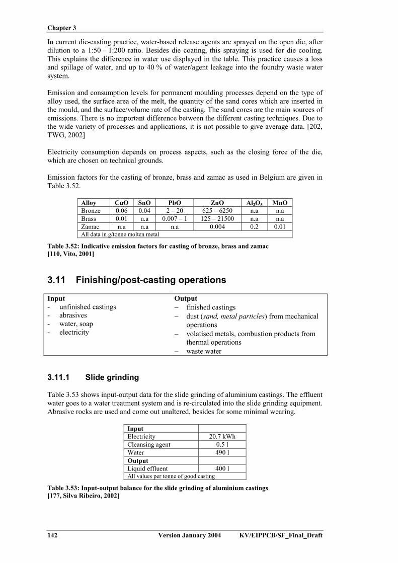
Chapter 3
142 Version January 2004 KV/EIPPCB/SF_Final_Draft
In current die-casting practice, water-based release agents are sprayed on the open die, afterdilution to a 1:50 – 1:200 ratio. Besides die coating, this spraying is used for die cooling.This explains the difference in water use displayed in the table. This practice causes a lossand spillage of water, and up to 40 % of water/agent leakage into the foundry waste watersystem.
Emission and consumption levels for permanent moulding processes depend on the type ofalloy used, the surface area of the melt, the quantity of the sand cores which are inserted inthe mould, and the surface/volume rate of the casting. The sand cores are the main sources ofemissions. There is no important difference between the different casting techniques. Due tothe wide variety of processes and applications, it is not possible to give average data. [202,TWG, 2002]
Electricity consumption depends on process aspects, such as the closing force of the die,which are chosen on technical grounds.
Emission factors for the casting of bronze, brass and zamac as used in Belgium are given inTable 3.52.
Alloy CuO SnO PbO ZnO Al2O3 MnOBronze 0.06 0.04 2 – 20 625 – 6250 n.a n.aBrass 0.01 n.a 0.007 – 1 125 – 21500 n.a n.aZamac n.a n.a n.a 0.004 0.2 0.01All data in g/tonne molten metal
Table 3.52: Indicative emission factors for casting of bronze, brass and zamac[110, Vito, 2001]
3.11 Finishing/post-casting operations
Input Output- unfinished castings- abrasives- water, soap- electricity
� finished castings� dust (sand, metal particles) from mechanical
operations� volatised metals, combustion products from
thermal operations� waste water
3.11.1 Slide grinding
Table 3.53 shows input-output data for the slide grinding of aluminium castings. The effluentwater goes to a water treatment system and is re-circulated into the slide grinding equipment.Abrasive rocks are used and come out unaltered, besides for some minimal wearing.
InputElectricity 20.7 kWhCleansing agent 0.5 lWater 490 lOutputLiquid effluent 400 lAll values per tonne of good casting
Table 3.53: Input-output balance for the slide grinding of aluminium castings[177, Silva Ribeiro, 2002]

Chapter 3
KV/EIPPCB/SF_Final_Draft Version January 2004 143
3.11.2 Shot blasting
Emission levels from the exhaust gas of shot blasting have been collected in an Italianfoundry survey. The results are displayed in Table 3.54. All techniques reach maximum dustemission levels below 30 mg/Nm³. The average value is below 15 mg/Nm³. The wet Venturisystem is the least effective system, leaving an emission factor well above those for the othertechniques. On the other hand, it also acts as is a safety device to prevent an aluminium-dust-explosion [225, TWG, 2003].
Concentration (mg/Nm³) Emission factor (g/tonne)Average Minimum Maximum Average Minimum Maximum
Bag filter 5.3 0.4 19.3 53.1 0.3 327.3Wet filtration 12.0 4.2 16.4 21.9 7.9 30.1Wet multi-cyclone 8.2 4.2 14.8 54.9 18.5 135.4Wet Venturi system 12.8 1.1 22.3 149.0 2.3 523.5Emission factor data in g/tonne of good casting and for cleaned gas
Table 3.54: Emission data for the exhaust gas from shot blasting, using various dedustingtechniques[180, Assofond, 2002]
3.11.3 Fettling
Emission levels from the exhaust gas of fettling have been collected in an Italian foundrysurvey. The results are displayed in Table 3.55. All techniques achieve dust emission levelsbelow 30 mg/Nm³. The bag filter and Venturi allow maximum levels below 10 mg/Nm³. Thewet multi-cyclone is the least effective system, leaving an emission factor well above thosefor other techniques. The emission factor is largely dependent on the amount of finishingneeded and thus the type of castings made.
Concentration (mg/Nm³) Emission factor (g/tonne)Average Minimum Maximum Average Minimum Maximum
Bag filter 3.0 0.4 7.5 17.0 2.3 85.6Wet multi-cyclone 14.8 7.6 23.3 275.6 96.2 497.2Wet Venturi system 2.5 1.1 5.9 45.5 35.5 63.4Emission factor data in g/tonne of good casting and for cleaned gas
Table 3.55: Emission data for the exhaust gas from fettling, using various dedusting techniques,[180, Assofond, 2002]
3.11.4 Finishing operations in steel foundries
Concerning steel foundries, specific cutting, scarfing and welding processes are used.Average dust emission values are given in Table 3.56. These apply for the use of thefollowing techniques:- Cutting (of runner system): Tetrene-acetylene-iron oxide for stainless cutting- Scarfing: Carbon electrode covered with copper- Welding: Using electrodes or wire.
Finishing technique Dust emission(kg/tonne)
Tetrene cuttingScarfingElectrode/Wire
11 - 139 - 113 - 3.5
All values in kg per tonne of good casting
Table 3.56: Average dust emission from steel finishing[202, TWG, 2002]

Chapter 3
144 Version January 2004 KV/EIPPCB/SF_Final_Draft
3.12 Heat treatment
Input Output� finished castings� energy (electric, gas or fuel oil)� quenching: water, oil, air
� finished casting (heat treated)� combustion products from firing� water vapour, fume, oil mist� NOx, SO2
The emissions from heat treatment furnaces mainly comprise combustion gases, particularlyfrom gas- and oil-fired furnaces. The composition of the combustion gases depends on thefuel-type used. Oil-fired furnaces will generate SO2-emission, which are not present fornatural gas burners. Where quenching processes are carried out, emissions of fume, watervapour, or oil mist will also occur, depending on the quenching media.
Heat treatment furnaces are known to be continuous sources of well known non-aircomponents. Emission levels are closely related to energy consumption, burner design andmaintenance. Emission collection is trivial in annealing furnaces. The capture of theemissions in the different furnaces does not differ considerably, and emissions are expelledvia the waste gas pipe. In general, no further waste gas treatment is applied.
Generally, quenching is a batch process. For this reason emission levels alternatesubstantially. Emissions from the quenching baths are regarded mostly to be irrelevant forthe environment, although they may become more relevant with large scale production. Dataabout source strength (emission rates) and chemical compounds have not been found.[32, CAEF, 1997]
3.13 Waste water
3.13.1 Sources of waste water
The amount of process water used in foundries is small and mainly depends on the selectionof techniques for dedusting. Waste water is generated mainly in dust removal and waste gastreatment systems, which are applied in the melting shop, moulding material preparation andreclamation and in the cleaning shop. Waste water is also generated in core production, ifwet scrubbers are used (depending of the core-making technique and bonding agents used).In a minority of plants (2 plants reported in Europe), water is used for wet sand regeneration.Furthermore, water is generally used for cupola shell cooling and for the cooling baths for(die) castings.
Possible sources of waste water are:- scrap storage area and site-drainage- sand preparation- wet scrubbers used for dedusting in various areas of the foundry- cooling of pressure die casting machines and tools- vibratory finishing (slide grinding)- cooling baths used for heat treatment.
The production-specific waste water quantity averages 0.5 m3/t good castings.
[160, UK Environment Agency, 2002], [195, UBA, 2003]

Chapter 3
KV/EIPPCB/SF_Final_Draft Version January 2004 145
3.13.2 Waste water from scrap storage
Scrap may have adhering soil, and external scrap typically exhibits production-specificimpurities. The adhering impurities may be washed off when it rains and may then enter thesoil and groundwater. An overview of the possible impurities is given in Table 3.57:
Scrap type Adhering impuritiesSwarf Cutting oils, emulsions (may contain chlorine)Punching scrap Punching oils (may contain chlorine)Broken machine castings,not conforming to specifications
Hydraulic oils, gear oils
Scrap from cold forming and smitheries Phosphates, zinc soaps, graphite, forming oils
Table 3.57: Possible impurities for specified scrap types[195, UBA, 2003]
If the adhering impurities are substances constituting a hazard to water (oils, emulsions),then requirements on the storage of substances constituting a hazard to water must becomplied with.
3.13.3 Waste water from wet scrubbers used in cupola melting
Wet scrubbers are in use in melting shops to clean the cupola off-gas. Wet scrubbers usewater to remove dust particles (average loading: 10 – 15 g/Nm3) and gases such as sulphurdioxide from cupola off-gas. In the settling tank, a large part of the solid particles arecaptured and thereby almost completely removed from the scrubbing water.
The partly acid gases washed out of the cupola off-gas, such as sulphur dioxide, accumulatein the scrubbing water, causing its salt concentration to increase (e.g. the formation of e.g.sodium sulphate) and its pH to decrease. This salt accumulation is supported by evaporationlosses, so it is necessary to draw the water off from time to time.
Waste water from wet dedusting systems in melting shops mainly contains:- solids such as oxides of silicon, iron and aluminium, calcium carbonates and cyanides- heavy metals, although with the exception of zinc, these are present only in very low
concentrations- organic pollutants, which can enter waste water via soiled scrap.
AOX (absorbable organic halides) levels in water used for the scrubbing of cupola off-gascan amount to several milligrams. Possible causes of AOX are scrap coatings and adheringchlorinated organic compounds entering the water during the gas scrubbing process.Chlorinated organic compounds can also reach the water via auxiliaries, such as commercial-grade hydrochloric acid or iron and aluminium chlorides, which are used as flocculants.
Table 3.58 gives an overview of the pollutant concentrations in filter effluent from thedewatering of sludge from the wet scrubbers of cupola furnaces.

Chapter 3
146 Version January 2004 KV/EIPPCB/SF_Final_Draft
Analyte Units ValuepH value 7.2 - 9.9El. conductivity �S/cm 1400 - 18400Lead mg/l <0.01 - 2.5Cadmium mg/l <0.01 - 0.03Chromium mg/l <0.01 - 0.13Copper mg/l 0.02 - 0.89Nickel mg/l 0.04 - 0.23Mercury mg/l < 0.001Zinc mg/l 1.8 - 27.9Sulphate mg/l 430 - 1550Chloride mg/l 1330 - 3947COD mg/l 154 - 7580
Table 3.58: Pollutant concentrations in filter effluent from dewatering the sludge from the wetscrubbers of cupola furnaces[195, UBA, 2003]
3.13.4 Waste water from the casting, cooling and shake-out area andfrom mould production/sand preparation
In the casting, cooling and shake-out area and in mould production/sand preparation,insoluble fines from the moulding material are captured during dedusting, along with smallorganic proportions from the bonding agent used. If wet dedusting is applied, thesecompounds are found in the waste water flow. The inorganic solids are iron oxides and clays,which are in part finely dispersed and difficult to remove.
3.13.5 Waste water from core-making
In core-making shops, chemical scrubbers are in use. They use either acid (cold-box process)or basic (SO2-process and Croning). The quantity of waste water discharged is dependentupon the accumulation of pollutants and salts in the circulating water. If pollution levels aretoo high, part of the polluted water must be drawn off.
Scrubbing solutions from cold-box and hot-box core-making contain readily biodegradableamines and phenols.
The treatment of amine-containing scrubbing solutions requires a nitrification/denitrificationstage. These treatment steps can also be carried out in an external biological waste watertreatment plant. An alternative to discharge is the recovery of the amines.
Following oxidation, scrubbing solutions from the SO2 process mainly contain sodiumsulphate. Since high sulphate concentrations (>600 mg/l) can lead to damage to seweragesystems, a limit value is set by the respective competent authority according to localconditions (e.g. the presence of sulphate-resistant piping and dilution with other wastewater).[195, UBA, 2003]

Chapter 4
KV/EIPPCB/SF_Final_Draft Version January 2004 147
4 TECHNIQUES TO CONSIDER IN THE DETERMINATION OFBAT FOR FOUNDRIES
In this section, techniques for environmental protection and energy saving measures are givenfor individual processing steps. The various techniques are structured into generic topics, whichallows a thematic approach to be taken for assessing the various different foundry processes andsteps.
The techniques all aim to either optimise the process or to reduce the environmental effects by,e.g.:- careful selection and optimisation of each unit operation i.e. in: storage, melting and metal
treatment, mould and core production, casting- the reduction of emissions to air and water- the increase in the efficient use of energy- the minimisation and re-use of residues.
In line with the thematic approach, information has been organised in the following sections:4.1. Raw material storage and handling4.2. Metal melting and molten metal treatment4.3. Mould- and core-making, including sand preparation4.4. Metal casting4.5. Fume, flue-gas and exhaust air capture and treatment4.6. Waste water treatment4.7. Energy efficiency4.8. Sand: regeneration, recycling, re-use, disposal4.9. Dust and solid residues: treatment and re-use4.10. Noise reduction4.11. Decommissioning4.12. Environmental management tools.
In order to allow the selection of best available techniques, all techniques to be considered in theBAT decision are presented according to a standard structure. The items of this structure areexplained in Table 4.1.
Name of the type of information Type of information includedDescription Technical description of the techniqueAchieved environmental benefits The main environmental impacts addressed by the technique.Operational data Data on consumption and emission levels from operational plants
using the technique. Any other information on how to operate,maintain and control the technique
Cross-media effects Any side effects and disadvantages to other media, caused byimplementation. Environmental effects of the technique incomparison with others
Applicability Indication of the type of plants in which the technique may beapplied, considering e.g. plant age (new or existing), plant size(large or small), techniques already installed (i.e.furnace type,moulding technique, …) and type of product (ferrous, non-ferrous)
Economics Information on costs (both investment and operational) andpossible savings, including details on how these costs have beencalculated
Driving force for implementation Local conditions or requirements which lead to or may stimulateimplementation. Information on reasons other than environmentalones for implementation (e.g. increase in productivity, safety)
Example plants Reference to plants in which the technique is applied and fromwhich information has been collected
Reference literature Literature which was used in writing the section and which containsmore details
Table 4.1: Information contained in the discussion of each technique included in Chapter 4

Chapter 4
148 Version January 2004 KV/EIPPCB/SF_Final_Draft
This chapter presents the information for each technique. The later balancing and selection oftechniques will be dealt with in Chapter 5, but based on the information of Chapter 4.
4.1 Raw material storage and handling
4.1.1 Introduction
The storage and handling of solid materials, gases and liquids is discussed in the Storage BREF[205, European IPPC Bureau, 2003]. The document discusses available techniques for e.g.heaps, silos, tanks and packaged materials (e.g. dangerous and flammable substances). Theseare applicable for foundry raw materials such as sand, scrap, coke, fuels (gas, oil), chemicals,additives and for residues such as used foundry sand, filter dust and slags. In this section, wewill only discuss foundry-specific issues which are not covered by the storage BREF.
4.1.2 Covered storage and impermeable scrap yard
DescriptionThe scrap storage area can be structured and managed in such a way that the following factorsare taken into account:- the composition of the furnace charge necessitates knowledge of the feed material.
Applying separate storage for various metal types or grades allows control of the chargecomposition. This can be achieved using compartments or boxes in the storage area orbunker
- the introduction of mineral and oxide materials such as rust, soil or dirt causes increasedrefractory wear. The use of a cemented scrap yard prevents the entrainment of soil, dirt orwater
- a roof constructed over the storage area can help keep rainwater out and can help containdust emissions.
- a water collection and treatment system can be used to prevent pollution to soil or water.
Achieved environmental benefitsThe use of a roof and a reinforced yard allows the collection of run-off water and thereforeprevents uncontrolled emissions to water and soil. Direct emissions to soil are also minimisedsince mixing of the material with soil is prevented.
Cross-media effectsNo cross-media effects apply.
ApplicabilityThe use of an impermeable scrap yard can be applied in the storage of scrap in all new andexisting foundries. Scrap is stored under a roof or with the provision of a water collection andtreatment system to prevent water and soil pollution.
Driving force for implementationControl of the charge composition improves control of the furnace operation and hence themetal composition. Also allows the minimisation of refractory wear.
Example plantsThis technique is applied in the majority of the foundries.
Reference literature[202, TWG, 2002]

Chapter 4
KV/EIPPCB/SF_Final_Draft Version January 2004 149
4.1.3 Storage measures for binder chemicals
DescriptionBinder chemicals carry specific manufacturer’s recommendations for storage. Failure to complywith these recommendations will result in unusable or sub-standard products that either requiredisposal as special waste or lead to poor casting quality due to sub-standard moulds/cores. Table4.2 summarises the quality problems arising from the incorrect storage of liquid binderchemicals. Correct storage takes account of these problems.
Problem Effect on product Implications Effect on castingsExposure to excessivecold
Aqueous-basedproducts may freeze
Product segregationmay occur, causingmould failure. Affectedproducts requiredisposal
Casting production maynot be possible
Exposure to excessiveheat and sunlight
Premature ageing,cross-linking of resinand increased viscosity
Poor mixing properties,low mould strengthsand poor resistance tohigh temperatures
Fining defects
Prolonged storage orcold storage
Increased viscosity Dispersion onto sandgrains difficult.Sand mixture flows lesswell and is difficult tocompact. Low-strengthmoulds
Erosion, exogenous(sandy) inclusionsfinning and dimensionalfaults
Contamination bymoisture
Products containingisocyanates willdeteriorate due toreaction with water
Binder performance ispoor and product mayneed disposal
Increased risk of gasdefects (pinholes)
Sediment disposal inbulk silicate storagetanks
Pumped liquid maybecome inconsistent
Low-strength moulds Oversize castings andshrinkage effects
Table 4.2: Problems arising from an incorrect storage of liquid binder chemicals[71, ETSU, 1998]
Some basic measures include:- roofed and ventilated area- collection of spilled liquid- locked storage area.
Depending on the climate, exposure to excessive cold or heat, and sunlight can be accountedfor. Additional precautions are necessary for the storage of highly flammable liquids such asmethyl formate, triethylamine (TEA), dimethylethylamine (DMEA) and mould coatingscontaining isopropyl alcohol.
Achieved environmental benefitsReduction of the amount of waste chemicals arising, which are unsuitable for use.
Most binder chemicals are hazardous, and are characterised by one or more of the followingproperties: toxic, corrosive, flammable. These properties mean that even small spills can pose adanger to worker’s health and safety, while larger releases can result in a serious incident. Amajor spill that is allowed to enter a surface water drain can cause serious pollution ofwatercourses.
Cross-media effectsNo cross-media effects apply.
ApplicabilityThis technique applies to all new and existing installations.

Chapter 4
150 Version January 2004 KV/EIPPCB/SF_Final_Draft
Driving force for implementationSafety measures and optimisation of foundry operations.
Example plantsThis technique is applied in the majority of the foundries.
Reference literature[75, ETSU, 1996]
4.1.4 Use of clean scrap for melting and removal of sand from thereturn material
DescriptionMelting clean scrap prevents the risk of non-metal compounds being taken up by the slag and/orattacking the furnace lining. These compounds are typically lime, iron oxides, manganeseoxides, and basic oxides (e.g. MgO from nodular iron returns) in combination with siliconrefractory (acid). If the amount of contamination is limited, this will reduce the amount of slagformed and will allow a longer lifetime of the furnace and ladle lining. For nodular ironproduction using a furnace with acid refractory, the adhering silica sand may have a beneficialeffect, since it neutralises the MgO coming from foundry returns.
The presence of contaminants and oxides in the furnace load, will consume part of the meltingenergy. Furthermore, the removal of slags necessitates a higher bath temperature to keep theslags in a liquid state.
Internally recycled scrap consists of feeders systems and rejected casting. Feeder systems areknocked off after shake-out. In general they do not retain adhering sand, due to their geometry.Rejected castings are excluded upon quality control, which is carried out after the castings arecleaned using sand blasting or shot blasting to remove all adhering sand. The use of sand-freereturn material therefore, in general, necessitates no extra treatment.
Achieved environmental benefitsThis technique reduces the amount of slags and dust that need disposal and limits VOC-emissions. The energy consumption is reduced (by 10 to 15 %) due to the reduced amount ofslag. Additionally the extracted airflow may be reduced.
Shot blasting of the scrap can be recommended for scrap where its contamination would lead tothe production of excessive amounts of slag. The use of only shot-blasted scrap would actuallyrequire slag-forming additives to create the slag.
Cross-media effectsIf foundries only accept clean scrap, the overall recycling rate for dirty scrap will reduce. Thiswill generate a need for additional cleaning operations and increase the disposal of scrap.
The use of cleaning techniques to remove sand from return material consumes energy. This isbalanced however by the energy gained in the melting stage.
Operational dataAn energy consumption to clean 30 - 40 kg of sand from 1 tonne of casting of 12 - 15 kWh hasbeen reported for an operational foundry. The consumption level is dependent on the size andtype of casting.
For a steel foundry using EAF melting, an increase in molten metal recovery (pouredmetal/charged metal) of 2 to 3 % has been reported.A typical metal charge for EAF is: 55 % foundry steel scrap; 40 % internal returns; 5 % metalcorrection additions.
Chapter 4
KV/EIPPCB/SF_Final_Draft Version January 2004 151
ApplicabilityThe removal of sand from internal scrap can be applied in all new and existing foundries. Theuse of clean scrap for melting can be applied in all foundry types, but the choice of the scrapgrade should be related to the techniques installed for melting and gas cleaning. If the wholesector shifts to clean scrap, this will generate a problem for the recycling of dirty scrap.
The use of clean ferrous scrap (both steel and pig iron) will lead to increased purchase costs andwill require investment in new cleaning equipment. There are no difficulties caused by scrapsurface oxidation nor by using pig iron ingots during melting in cupola furnaces (reductionprocess). Electric furnaces will have difficulties only with contaminated scrap which does notcomply with the parameters for steel scrap used in foundries.
Cupola furnaces can easily melt scrap which is not clean. There is little coke overconsumptionand little environmental consequence, if the gases are correctly treated.
Limiting the slag is very important for good operation of the coreless induction furnace. Theoperation is more affected by the scrap cleanliness than the other furnace types.
The use of dirty scrap has no adverse effects on rotary furnace operation but is the maindetermining factor for dust emissions. There is little environmental consequence if the gases arecorrectly treated.
EconomicsThe price for clean scrap (i.e. class 1) is 20 to 30 % higher than that for contaminated (i.e.class 2) scrap. Furthermore, disposal costs for slags and dust are reduced by applying thistechnique.
Driving force for implementationHigh disposal fees for residues and high prices for the refractory.
Example plantsThis technique is commonly applied in foundries.
Reference literature[103, Vereniging van Nederlandse Gemeenten, 1998], [110, Vito, 2001], [202, TWG, 2002]
4.1.5 Internal recycling of scrap ferrous metal
DescriptionInternal scrap is produced from the knock-off of feeders and runners, in quality control and infinishing operations. The relative amount of internal scrap produced can be calculated from themetal yield as defined and described in Section 3.10.1.3. In order to minimise residueproduction, internal scrap is returned to the scrap metal feed of the furnace.For steel foundries, a 100 % use of return metal is uncommon, due to the amount of dissolvedgas. Operators consider 60 % to be the maximum amount of return metal (feeders, scrapcastings,...) in the charge metal. Swarf and turnings may cause excessive molten metaloxidation.
Internal scrap recycling may also be limited in the case of nodular base iron melting, as a highamount of silicon (about 1 % in most cases) is added in the liquid iron during the metaltreatment. In some cases re-melting the whole internal scrap is not possible because the finalsilicon would be too high (typically 2.5 – 3 % in the castings).
In the case of grey or nodular iron, lead or bismuth are very noxious for the properties of themetal after solidification. If there has been a pollution incident the returns (internal scrap) mustnot be recycled.

Chapter 4
152 Version January 2004 KV/EIPPCB/SF_Final_Draft
Achieved environmental benefitsMinimisation of residues through recycling of raw materials.
Cross-media effectsNo cross-media effects apply.
ApplicabilityThis technique applies to all new and existing installations.
EconomicsThe technique does not involve any additional costs.
Driving force for implementationMinimisation of residues, optimal use of metal.
Example plantsThe technique is applied in all European foundries.
Reference literature[202, TWG, 2002]
4.1.6 Internal recycling of magnesium scrap
Description“In cell” recycling:Clean feeders can be directly melted in the melting furnaces. Because of oxides and otherinclusions, the possible amount of recycling is limited. Specialised equipment for exactanalytical and metallographical control is necessary.
“In house recycling”:Here the scrap is treated and recycled at a separate recycling-plant on-site at the foundry. Twotechniques may be applied:- Fluxless re-melting: Re-melting of Mg scrap under a covering gas in a hearth type furnace;
applicable only to class 1 scrap. Advantages are the low additional investment and lowenergy consumption
- Salt re-melting: Re-melting of Mg scrap under a salt cover. Is applicable to the processingof all scrap classes except used fluxes and sludge (not treated). If only class 1 – 2 scrap isused, HP (high purity) magnesium alloys may be produced.
Both techniques can be used to produce Mg-ingots or molten metal for liquid charging.Both in fluxless and salt-covered re-melting, dross (the floatings on the melt) and sludge (thesinkings in the melt) are generated, as well as residues retaining a residual metal content(70 - 80 % Mg for sludge, 60 – 90 % Mg for dross). For recovery of the metal content, threeoptions exist:- salt re-melting (in the same or a separate furnace)- re-melting in the aluminium industry- utilisation in the desulphurisation of iron or steel.
If the scrap is re-melted in a fluxless melting furnace, the salt re-melting of dross and sludgeinvolves the operation of a separate furnace.
The re-melting of mixed class scraps is performed using salt re-melting. The mixed scrap needspretreatment. Table 4.3 gives a survey of the input-outputs of a pretreatment installation.

Chapter 4
KV/EIPPCB/SF_Final_Draft Version January 2004 153
Inputs Equipment Outputs End-of-pipetechnology
- oily or wet Mg-turnings (>2 %oil/water)
- electricity
Centrifuge - Mg-turnings (<2 %oil/water)
- oil/water-emulsion- centrifuged and all other
turnings- electricity
Turning–press(T = 400 °C)
- pressed turning- exhaust air
Particle separatorfor the vaporised oil
- feeders, bad castings- dross (without salt, from the
foundry process)- electricity
Shredder(if necessary)
- shredded material- dust
Table 4.3: Inputs and outputs for a magnesium scrap treatment plant[202, TWG, 2002]
The recovery of metal from the re-melting salt residue is done using dry crushing and screeningwith magnetic separation or by using a wet washing system. The wet system produces amagnesium fraction and a sludge, which, after dewatering, may be used in fertiliser industry.
Achieved environmental benefitsThe main benefit is the optimised recycling of magnesium. Internal recycling has the addedbenefit of eliminating transport to an external recycling plant. The metal efficiency of therecycling is increased by type-specific melting.
Cross-media effectsFluxless re-melting involves the use of sulphur containing protective gases, which contribute toglobal warming (SF6) or are poisonous (SO2). This issue is discussed in 4.2.7.1.
Operational dataExperimental mass flow diagrams for the re-melting of class 1 scrap are given in Figure 4.1 andFigure 4.2. These include the internal re-melting of sludge and dross.
Figure 4.1: Mass flow diagram for the fluxless re-melting of magnesium class 1 scrap[206, Ditze and Scharf, 2000]

Chapter 4
154 Version January 2004 KV/EIPPCB/SF_Final_Draft
Figure 4.2: Mass flow diagram for the salt re-melting of class 1 magnesium scrap[206, Ditze and Scharf, 2000]
Operational data from a 2000 tonne/yr salt re-melting plant for mixed treated scrap (3 furnaceswith a capacity of 600 kg each) give consumption levels of salt: of 3.4 kg/tonne scrap andnatural gas: of 26.5 Nm³/tonne scrap.
The wet treatment of the salt fraction produces a magnesium fraction (43 %) and a sludge(57 %). The sludge is dewatered using a membrane filter press and the water is re-circulatedinto the process.
ApplicabilityThis technique is applicable for new and existing magnesium foundry installations.
EconomicsCosts for external recycling are estimated to be approximately EUR 1200/tonne, depending onthe type of transport used, the transport distance and the local market. The costs for in-houserecycling are EUR 500/tonne, a difference of EUR 700/tonne. For a single plant with 1500tonnes/yr recycling material this means a potential saving of more than one million euros peryear.
The given data are general and have to be adapted individually for each enterprise. Dependingon the products and the processes used, the expenses needed for separation of the waste have tobe taken into account. The waste has to be collected specifically for every alloy and everyprocedure.
Further factors of major influence are:
- depreciation (approximately 10 % in a depreciation period of 5 years)- personnel costs (35 – 40%)- cost for new material (approximately 30%) to substitute the material loss (estimated 7%)- costs for energy, maintenance, spare parts, salt, disposal (20 – 25%).
The amortisation of a flux-based facility with two furnaces is in the range of 8 to 11 months.The amortisation of a continuous facility with 500 kg magnesium per hour will likely take a fewmonths more.
Driving force for implementationOptimisation of magnesium use, with a reduction of the amount of magnesium sent for disposal.

Chapter 4
KV/EIPPCB/SF_Final_Draft Version January 2004 155
Example plantsTCG Unitech, Kirchdorf/Krems (A): uses an in-house recycling facility.No fluxless re-melting plants have been reported in Europe, although the melting technology isavailable on the market.
Reference literature[202, TWG, 2002], [206, Ditze and Scharf, 2000], [223, Rauch, et al., 2003]
4.1.7 Recycling of used containers
DescriptionSuppliers of chemicals and additives may take back their empty containers (plastic, wood,metal) for recycling. The use of the largest size container possible may be considered.
Achieved environmental benefitsPrevents waste and further stimulates recycling.
Cross-media effectsIf containers are returned without further cleaning, no cross-media effects apply.
ApplicabilityThis technique is applicable in all new and existing installations.
EconomicsEconomic data differ from site to site and depend on the conditions agreed with the supplier.
Driving force for implementationPrevention and recycling schemes for waste and packaging waste regulations.
Example plantsThis technique is commonly applied in European foundries.
Reference literature[110, Vito, 2001]
4.2 Metal melting and molten metal treatment
4.2.1 Cupola furnaces
In this section, techniques concerning melting practices and furnace operation will be discussed.These techniques may apply either to cold or hot blast operation, or to both. Flue-gas relatedtechniques, such as post combustion and flue-gas cleaning, are discussed in Section 4.5.2. Thatsection also discusses the conversion of cold blast to hot blast cupola furnaces.
4.2.1.1 Optimisation of furnace operation
DescriptionThe amount of dust and exhaust gases resulting are directly related to the amount of cokecharged per tonne of iron. Therefore, all measures that improve the thermal efficiency of thecupola will also reduce the emissions from the furnace.

Chapter 4
156 Version January 2004 KV/EIPPCB/SF_Final_Draft
Possible good melting practice measures include:
- Operating the furnace in its optimum regime as much as possible: For any given cupola, theinfluence of the blast rate and the coke charge on the tapping temperature of the metal andthe melting rate, can be expressed in the form of a net diagram or Jungblüth diagram. A netdiagram is only valid quantitatively for the cupola for which it was obtained. It displayshow the metal temperature and melting rate behave upon changes in the blast rate and cokecharge, and allows determination of the point (or line) of optimal thermal efficiency
- Avoiding excess temperatures of the melt and reducing the superheating temperatures bytaking measures during the handling of tapped metal
- Uniform charging: taking care during charging to get a uniform distribution of metal andcoke
- Improving the control of the charge weight, the blast airflow and the metal temperature- Minimising air losses: The correct supply of air is essential for efficient cupola operation.
This is often hampered by air losses. Therefore, it is important to pay close attention to theprevention of all leaks to ensure efficient operation. Slag holes on intermittently tappedcupolas are often left open and are frequently oversized, resulting in considerable air losses.Air losses are particularly common for hot blast cupolas. They take place in the heat-exchanger. The consequence is that oxygen must be injected in the tuyères instead of the airwhich is lost
- Avoiding “bridging” in the cupola: Bridging and scaffolding are the hanging or non-descentof cupola charges in the cupola shaft. This causes a loss of melting efficiency, and in severeinstances melting can be completely stopped
- Utilising good lining practice: As melting proceeds, the diameter and the area of the meltingzone increase due to lining erosion and wear. This affects the operation, moving it awayfrom the optimum. Minimising the lining attack is therefore an energy saving measure. Forsatisfactory and economic cupola operation the melting zone needs to be efficiently repairedafter each melt.
Achieved environmental benefitsIncreased energy efficiency, reduction of cokes consumption, reduction of residues.
Cross-media effectsNo cross-media effects are reported
ApplicabilityThis technique applies to all new and exisiting cupola furnaces.
Driving force for implementationOptimisation of furnace operation.
Example plantsGood melting practice measures are applied in all cupola foundries.
Reference literature[32, CAEF, 1997], [44, ETSU, 1993], [202, TWG, 2002]
4.2.1.2 Quality control of coke input
DescriptionThe quality of the coke used has a direct bearing on the efficiency of cupola operations. Itparticularly affects the initial temperature carbon pick-up and the sulphur content of the iron.Specifying the foundry coke involves testing the following contents:

Chapter 4
KV/EIPPCB/SF_Final_Draft Version January 2004 157
- Fixed carbon: The higher the carbon content, the higher the calorific value- Ash content: A high ash content is undesirable since it lowers the calorific value of the coke
and generates a greater volume of slag in the cupola- Volatile matter: Volatile matter is undesirable since it reduces the fixed-carbon content, and
thus the calorific value of the coke- Sulphur: Sulphur is well known as an unwanted element in any type of cast iron and leads
to SO2 emissions. The lower the sulphur content of the feedstock coke, the better. Thesulphur content of the coke depends on the sulphur content of the feedstock coal.Unfortunately there is no known method to remove sulphur from coal
- Moisture: Moisture in the coke when dispatched from the coke oven is undesirable, since itreduces the amount of carbon available by weight. However, it is necessary for the coke tocontain some moisture, to avoid fires on conveyer belts and in lorries and wagons
- Size: The size of the foundry coke directly affects the coke consumption per tonne of ironmelted and also the melting rate. To achieve optimum performance the coke size dispatchedfrom the coke oven generally needs to be sized such that the furnace coke has a mean sizediameter greater than 90 mm, with no more than 4 % smaller than 50 mm. The content offines will influence emissions of dust during (un)loading and handling.
Achieved environmental benefitsOptimising the coke input results in a higher process efficiency.
Cross-media effectsNo cross-media effects apply.
Operational dataTypical properties of foundry coke are given in Table 4.4:
Property Typical value (%) Limit value (%)Ash 5.8 – 5.9 6.5 max.Volatile matter 0.3 – 0.4 0.8 max.Sulphur 0.68 – 0.70 0.75 max.Moisture 1.5 – 2.5 3.0 max.Strength
M80 Micus index 81 – 82 78.0 max.M10 Micus index 8 – 8.5 9.0 max.
Fixed carbon 93.7 – 93.8 93.0 min.Higher calorific value 32200 kJ/kg 31800 kJ/kg
Table 4.4: Typical properties of foundry cokes[197, Nalonchem, 2002]
The data in Table 4.4 are taken from supplier specifications. Local standards may use higherlimit values.
ApplicabilityThe technique is applicable to all new and existing cupola installations.
EconomicsIn general, low sulphur feedstocks are more expensive.
Driving force for implementationTo improve the efficiency of the foundry process.
Example plantsThis technique is commonly applied in European foundries using cupola furnaces.
Reference literature[44, ETSU, 1993], [225, TWG, 2003]

Chapter 4
158 Version January 2004 KV/EIPPCB/SF_Final_Draft
4.2.1.3 Operation with acidic or basic slag
DescriptionA flux is used to render the slag fluid enough to separate from the iron and to allow it to flowfreely from the cupola. The most commonly used flux is limestone (calcium carbonate), whichcalcines in the cupola shaft to form lime, a basic oxide, which then combines with the otherslag-forming constituents (mainly acidic in character) to provide a fluid slag.
The basicity of a slag is given by the following ratio: (CaO % + MgO %)/SiO2 %
Most cupolas operate with an acidic or slightly basic slag (basicity <1.2). Basic cupolas(basicity up to 2) offer 3 advantages:- higher carbon- lower sulphur- possibility of charging lower quality scrap.
But they present the following disadvantages:- silicon losses are high- refractory costs are high, unless operating with a liningless cupola- fluxing material costs are higher- metal analysis is more difficult to control than acid cupola melting.
Achieved environmental benefitsFor acidic cupolas, dry filters can be used. The slag of basic cupolas has a higher melting point.So a flux based on CaF2 is generally used to make it fluid. In this type of cupola, there areemissions of fluor-containing components. This necessitates the application of wet scrubbers forefficient capture of these components.
ApplicabilityThis technique applies to all new and existing cupola installations. If basic slag is used, a wetdedusting is necessary.
Example plantsThis technique is commonly applied in European foundries using cupola furnaces.
Reference literature[44, ETSU, 1993], [202, TWG, 2002], [225, TWG, 2003]
4.2.1.4 Increasing shaft height of CBC
DescriptionThe required shaft height for cupolas at various melting rates is given in Table 4.5. These shaftheights optimise the preheat for the descending burden. However, if the gas is to be burned atthe charge-hole, a shorter shaft height may be considered. In general, the shorter the shaft, thehotter the top gas and the greater the ease of combustion – either spontaneous or assisted by anafterburner.
Melting rate of Cupola(tonne/h)
Height from tuyèresto charging door sill
(m)Up to 5 4.95 – 8 5.8>8 6.7
Table 4.5: Shaft height requirements

Chapter 4
KV/EIPPCB/SF_Final_Draft Version January 2004 159
The thermal efficiency of the cold blast cupola furnace can be improved by increasing the shaftheight. In general, the higher the furnace shaft, the longer the combustion gases remain incontact with the charge, and the more heat is transferred to the charge.
Achieved environmental benefitsDepending on the installation type, the height must be optimised to allow burn-out of the gasesand efficient heating of the charge.
Cross-media effectsNo cross-media effects apply.
Operational dataOperational data are given in Table 4.6. The modification involves a doubling of the upper zonevolume. This results in a reduction of coke consumption from 140 to 115 kg/tonne, which is arelative reduction of 18 %. It should be noted that in general an optimal shaft height follows therule-of-thumb: ‘height = 5 x diameter at tuyères’. The initial situation in the example furnacewas therefore sub-optimal.
Cupolabefore modification
Cupolaafter modification
Diameter- melting zone (m) 1.4 1.4- upper zone (m) 1.4 1.7Heigth over tuyères (m) 5 6.5Coke ratio (kg/tonne) 140 115
Table 4.6: Example data for the change in coke consumption upon shaft height increases[202, TWG, 2002]
ApplicabilityOptimisation of the furnace height needs to be performed at the design stage of the furnace,otherwise height increases will usually only be performed during major re-building works of thefurnace.
Driving force for implementationTo increase the efficiency of the furnace operation.
Example plantsOperational data are taken from an example plant in France.
Reference literature[32, CAEF, 1997], [44, ETSU, 1993], [202, TWG, 2002]
4.2.1.5 Installation of secondary row of tuyères for a cold blast cupola(CBC)
DescriptionThe thermal efficiency of the cold blast cupola furnace can be improved by the installation of asecondary row of tuyères. These provide extra oxygen above the combustion zone, whichinduces the oxidation of the CO in the combustion gases, the CO being formed by theendothermic reduction of CO2 by C (coke). This technique liberates the “latent” heat of thecombustion gases, thus improving the thermal efficiency of the cupola.
The divided blast cupola is equipped with two rows of tuyères, each supplied with a measuredand controlled quantity of blast air. Compared with a normal cupola, fitted with a single row oftuyères, the divided blast cupola enables:
Chapter 4
160 Version January 2004 KV/EIPPCB/SF_Final_Draft
- a higher metal tipping temperature and higher carbon pick-up to be obtained for a givencharge-coke consumption
- the charge coke consumption to be reduced and, if required, the melting rate to be increased,whilst maintaining a given metal tapping temperature.
To obtain the maximum benefit from divided blast operation, the blast should be divided25 - 50 % top and 75 – 50 % bottom. The 2 rows should be spaced about 1m apart (cold blast)to 0.5 m (hot blast). Each row of tuyères needs to be provided with its own blast supply system.
Achieved environmental benefitsA reduction in coke consumption and an increase in thermal efficiency.
Cross-media effectsNo cross-media effects apply.
Operational dataBy the use of two rows of correctly-spaced tuyères with the blast equally divided between them,the metal tapping temperature can be increased by approximately 45 – 50 ºC for a given cokeconsumption. Alternatively, the coke consumption can be reduced by 20 – 32 % and the meltingrate increased by 11 – 23 %. When operating with a divided blast but without reducing the cokecharge, so that a higher melting temperature is obtained, the carbon pick-up tends to increaseslightly (by approx. 0.06 %), and the melting loss of silicon tends to also increase, byapproximately 0.18 %.
With divided blast operation, the lining burn-out extends further into the furnace shaft. At thestart of a melt it is therefore necessary to measure and adjust the coke bed height. On melts ofshort duration, i.e. those less than about 2 – 3 hours, the saving in coke charge does not usuallycompensate for the additional requirements of bed coke. Nevertheless, even on short melts, thehigher tapping temperature and the higher carbon pick-up obtainable with divided blastoperation can be an advantage to many foundries.
Other reported advantages are:- the exit gas temperature is only 250 ºC, compared to the conventional cupola, where the
temperature is 450 ºC- it can take 100 % bigger chunks of re-melting scrap- it is possible to increase the steel scrap ratio in the metal charge.
Additional operational data are given in Annex 1.
ApplicabilityThe second row of tuyères is applied as a standard technique for new cold blast cupolainstallations and may be applied to existing installations during reconstruction. This technique isnot normally applied for hot blast operation
EconomicsThe divided blast cupola has been well proven in practice as a means of obtaining economicoperation for a modest investment cost.
The capital cost of converting existing cupolas to divided-blast operation is low compared to thesavings obtained. BCIRA quoted one British foundry where the payback period was onlyfourteen weeks. A large Canadian foundry saved CAD 170000 in one year for a conversion costof only CAD 18000. An additional benefit from a lower coke use per tonne of iron is the lowersulphur content, this saves on the desulphurisation plant and gives a higher quality iron.
Additional economic data are given in Annex 1.

Chapter 4
KV/EIPPCB/SF_Final_Draft Version January 2004 161
Driving force for implementationTo increase the efficiency of the melting operation.
Example plantsIn France, all the recent cold blast cupolas use 2 rows of tuyères: STAUB (Merville), FONTEARDENNAISE (Vivier au court), BERNARD HUET (Vivier au court). There is also 1 hot blastwith 2 rows: FIDAY GESTION (Chassey les Scey)
Reference literature[32, CAEF, 1997], [196, Unido, 2002], [202, TWG, 2002], [225, TWG, 2003]
4.2.1.6 Oxygen enrichment of blast supply
DescriptionThe thermal efficiency of the cold blast cupola furnace can be improved by oxygen enrichmentof the combustion air. This gives rise to a higher combustion temperature of the coke. In thisway coke consumption can be decreased or higher temperatures of the tapped metal can beobtained.
Compared with normal operation, the continuous use of oxygen enables one of the followingimprovements to be made:- a higher metal temperature, higher carbon pick-up and lower melting loss of silicon for the
same coke consumption, or- a lower coke consumption for a given metal temperature, with no increase in carbon pick-up
or reduction in the melting loss of silicon, or- an increased output from an existing cupola, as a result of the increased melting rate.Oxygen injection provides the possibility of reacting quickly to process drifts, and thencompensating for small changes in process conditions. Thus, oxygen injection is often usedintermittently, usually whenever the process requires adjustment.
The effectiveness of the oxygen depends on the method by which it is introduced into thecupola. Three processes have been developed:- Direct enrichment of the blast supply: Oxygen is fed into the main blast, this technique is
applied in the majority of the cold blast cupolas- Injection into the well: Oxygen is injected into the coke bed from a ring-main which
supplies water-cooled injectors, whose number depends on the cupola size. Oxygen used inthis way is at least twice as effective as when it is used to enrich the blast supply directly.However, this type of injection is confined to continuously-tapped cupolas, since withintermittent tapping there is a risk that slag and or metal may rise to the level of theinjectors. The technique was developed in the UK but it has not found widespreadapplication
- Injection at the tuyères: Oxygen is introduced into the cupola through injectors inserted intoeach tuyère or into alternate tuyères. The effectiveness of this method lies between directblast injection and well injection methods. This technique is used in 20 – 30 % of cases, butmore in hot blast operation.
The principles of oxygen injection are depicted in Figure 4.3.

Chapter 4
162 Version January 2004 KV/EIPPCB/SF_Final_Draft
Figure 4.3: Various methods of oxygen injection[44, ETSU, 1993]
Achieved environmental benefitsThe application of oxygen results in a reduced coke consumption and a better process control.Additionally, a reduction in the emission of dioxins and furans from cold blast cupolas havebeen reported (see Section 4.5.1.4).
Cross-media effectsThe technique requires oxygen which is produced off-site and involves a consumption ofelectric energy.
Operational dataCompared to conventional cold blast operation with one row of tuyères, the increase in tappingtemperature obtained for a given charge of coke, can be expected to be as follows:- blast enrichment + 15 ºC- well injection + 85 ºC- tuyère injection + 40 ºC
Divided blast operation with a direct enrichment of blast air, results in an increase in the tappingtemperature of 85 ºC compared to cold blast operation. In divided blast operation, neither wellinjection nor tuyère injection give any greater benefit than the simple method of direct injection.
An important application of oxygen has been to increase the melting rate of an existing cupola,well beyond its usual optimum melting capacity. In divided blast cupolas, the melting rateincreases by around 6.8 % and the tapping temperature by about 20 ºC for each 1 % of directoxygen enrichment in the blast air. If an increase in temperature is not required and the cokecharge is reduced, an even greater increase in the melting rate can be obtained for the same blastrate and oxygen enrichment.
Additional operational data are given in Annex 1.
ApplicabilityToday, almost all European hot blast cupolas inject oxygen through the tuyères. For cold blastfurnaces, the use of oxygen enrichment can be considered as the standard technique. In this

Chapter 4
KV/EIPPCB/SF_Final_Draft Version January 2004 163
case, enrichment of the blast supply is usually applied. The oxygen level of the oxidising airmixture is usually between 22 and 25 % (i.e. an enrichment of 1 % to 4 %).
EconomicsThe effect that using oxygen has on melting costs greatly depends on the price of oxygen, whichin turn is related to the amount used. Foundries with larger outputs can generally buy oxygenmore cheaply. The economic case for using oxygen has to be established on a case-by-casebasis.
The substantial increase in outputs obtainable has enabled foundries to increase outputs withouthigh capital investments in new plant, and to reduce costs and overtime payments, so much sothat the overall reduction in costs amply justify the cost of oxygen. Such improvements musttake into account the related core and mould making capacity.
Driving force for implementationTo optimise the efficiency and control of the melting process.
Example plantsThis technique is commonly applied in European foundries using cupola furnaces.
Reference literature[32, CAEF, 1997], [156, Godinot, 2001]
4.2.1.7 Superheating of HBC blast air
DescriptionAn alternative technique for increasing the flame temperature is to superheat the blast air to800 – 900 ºC. For this, injection of an air plasma, or heating in tubular resistance heaters isapplied. Experience has shown that increasing the blast temperature by 200 ºC, from 550 ºC to750 ºC, which takes 60 kWh per tonne of iron, saves 10 kg of coke per tonne melted. The mainbenefit, more important even than saving coke, is the flexibility: the hourly output can beincreased by 30 % without modifying the melting bed. Additionally, the application of (plasma)superheating allows a change in raw material from clean cast iron to steel, with a subsequentpositive economic effect.
Achieved environmental benefitsReduced coke consumption and increased efficiency of the process.
Cross-media effectsElectrical heating causes an increase in electricity consumption (58 kWh/tonne).
Operational dataOperational data are given in Annex 1. The heating of the blast air produces a lower flue-gasvolume as compared to hot blast long campaign operation. As compared to oxygen injection,the flue-gas volume and electricity consumption is larger.
ApplicabilityThe technique applies to new and existing HBC furnaces.
The technique (both with electrical and plasma heating) achieves a similar effect as injection ofoxygen through the lances, but can be applied in a more complex installation and produces alarger flue-gas volume. Additionally, oxygen injection allows make-up for leaks in the aircircuit.
EconomicsEconomic data are given in Annex 1.

Chapter 4
164 Version January 2004 KV/EIPPCB/SF_Final_Draft
Driving force for implementationTo optimise the efficiency and to control the melting process.
Example plantsPSA, Sept-Fons, FranceThree foundries in France apply tubular resistance heating.
Reference literature[156, Godinot, 2001]
4.2.1.8 Minimal blast shut-off periods for HBC
DescriptionA cupola blown just intermittently will not operate efficiently, and will result in a reduced metaltapping temperature, as shown in Figure 4.4.
Figure 4.4: Effect of blast shut-off periods on tapping temperature in a post-blast cupola[44, ETSU, 1993]
Frequently shutting off the blast due to only intermittent demands for metal:- reduces the average tapping and pouring temperatures and increases the extent of their
variations, with a consequent risk of producing defective castings- increases the variation in metal composition, particularly the carbon and silicon content,
with a danger of then producing ‘off-grade’ metal- increases the coke consumption, through the operators’ attempt to improve the tapping
temperature- affects the degree of nucleation in the iron and increases its shrinkage tendencies.
Moulding and casting schedules are therefore programmed to produce a reasonably constantdemand for metal, thereby minimising or even eliminating the need for blast shut-off periods orfor large variations in the blast rate.
Where large fluctuations in demand are unavoidable, the installation of an electric holdingfurnace might be considered. This can provide a large buffer reservoir for metal, to take up

Chapter 4
KV/EIPPCB/SF_Final_Draft Version January 2004 165
variations in demand, so that the cupola can be operated continuously at a reasonably consistentblast rate. It can also be used to help even out variations in temperatures and composition.
Achieved environmental benefitsReduction of cokes consumption. Higher process energy efficiency.
Cross-media effectsOperating the electric holding furnace incurs a higher energy consumption.
ApplicabilityThis technique is applicable to all new and existing cupola furnaces.
EconomicsThe economics of installing a holding furnace must be very carefully considered, particularly infoundries with relatively low production rates.
Driving force for implementationTo increase the efficiency of the foundry process.
Example plantsThe applicable blasting regime is part of the operational considerations in all Europeanfoundries using cupola furnaces.
Reference literature[44, ETSU, 1993]
4.2.1.9 Cokeless cupola furnace
DescriptionIn the cokeless cupola, the metal charge is heated by the combustion of natural gas. Instead ofthe traditional coke bed, a bed of refractory spheres on a water-cooled grid supports the metalcharge. The molten metal droplets run through this bed and are collected in the well at thebottom of the furnace. The life of the spheres exposed to the superheating temperatures of themetal is limited. A cokeless cupola is therefore run at a reduced temperature (1400 ºC instead of1500 ºC) and superheating of the liquid metal is done in an attached gas-fired or inductionfurnace (duplex operation).
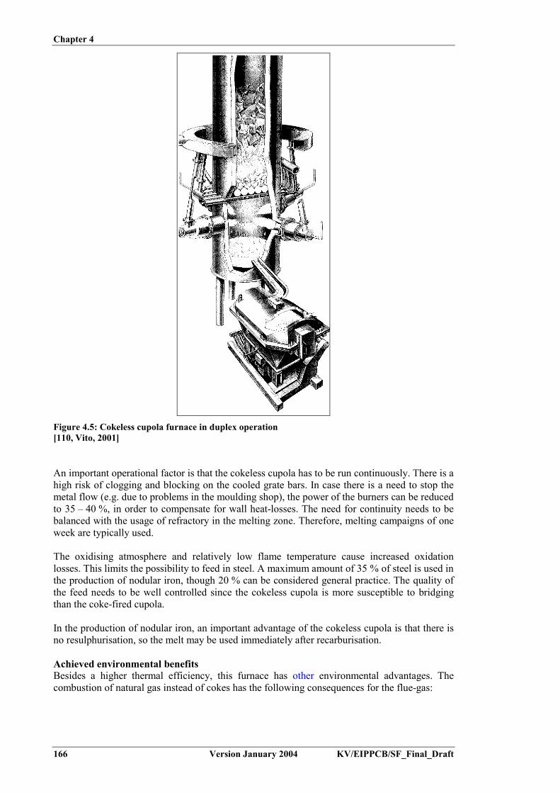
Chapter 4
166 Version January 2004 KV/EIPPCB/SF_Final_Draft
Figure 4.5: Cokeless cupola furnace in duplex operation[110, Vito, 2001]
An important operational factor is that the cokeless cupola has to be run continuously. There is ahigh risk of clogging and blocking on the cooled grate bars. In case there is a need to stop themetal flow (e.g. due to problems in the moulding shop), the power of the burners can be reducedto 35 – 40 %, in order to compensate for wall heat-losses. The need for continuity needs to bebalanced with the usage of refractory in the melting zone. Therefore, melting campaigns of oneweek are typically used.
The oxidising atmosphere and relatively low flame temperature cause increased oxidationlosses. This limits the possibility to feed in steel. A maximum amount of 35 % of steel is used inthe production of nodular iron, though 20 % can be considered general practice. The quality ofthe feed needs to be well controlled since the cokeless cupola is more susceptible to bridgingthan the coke-fired cupola.
In the production of nodular iron, an important advantage of the cokeless cupola is that there isno resulphurisation, so the melt may be used immediately after recarburisation.
Achieved environmental benefitsBesides a higher thermal efficiency, this furnace has other environmental advantages. Thecombustion of natural gas instead of cokes has the following consequences for the flue-gas:

Chapter 4
KV/EIPPCB/SF_Final_Draft Version January 2004 167
- less dust (0.8 kg/t metal charge instead of 10 to 15 kg/t metal charge for cold blast cupola)- no CO or SO2 and less CO2 (120 kg/t metal charge instead of 450 kg CO2/t metal charge for
cold blast cupola)- the flue-gas rate is smaller (495 m³/t metal charge instead of 770 m³/t metal charge for cold
blast cupola without water-cooled refractory), and hence the dedusting installation can bedesigned much smaller.
Cross-media effectsThe use of cokeless cupola melting necessitates duplex operation, in order to allow superheatingof the iron. For superheating in an induction furnace, there is an increased need for electricalpower compared to the hot blast operation.
Operational dataOperational data are given in Table 4.7. The furnace is generally operated at an air factor ofλ = 1.15. The capacity of the furnace may be high (often in the range 10 – 12 t/m².h). Theamount of spheres is 1 – 1.4 % of the metal charge. The energy efficiency of the cupola, withouttaking the coupled induction furnace into account, is in the range of 70 %.
Units Consumption(per tonne of molten
metal)Natural gas consumption Preheating of the furnace m³ 600
Melting m³ 48.0Electrical energy consumption a) Superheater
Superheating kWh 64.0Holding kWh 15.0
b) Auxiliary equipment kWh 25.0Consumption of lining material
Furnace shaft kg 5 – 8Syphon kg 0.7Superheater kg 0.5
Water consumption m³ 0.4Oxygen consumption m³ 19.7Metallic charge Components Part (%/t)
steel 25 – 35pig iron 20 – 30
returns/cast iron scrap 35 – 55Alloying and additives Components Part (%/t)
Carburiser 1.1Briquettes – Si 0.8Ceramic balls 0.95Slag formingconstituent
0.3
Table 4.7: Typical operational data for a cokeless cupola furnace[202, TWG, 2002]
Due to the absence of cokes (and CO), no latent heat is lost from the cokeless furnace system.Full heat recuperation from the flue-gas occurs in the shaft. In duplex configurations (forexample in conjunction with an induction furnace), efficiencies in the range of 40 to 60 % maybe obtained. Thermal efficiencies for coke fired cupolas vary between 25 % (cold blast) and45 % (hot blast, long campaign).

Chapter 4
168 Version January 2004 KV/EIPPCB/SF_Final_Draft
Emission data for cokeless and hot blast cupola furnaces are compared in Table 4.8. Theseapply for the following configurations:- cokeless cupola: below-charge exhaust capture; oxidising atmosphere (� = 1.15); no post
combustion; dry filtration- hot blast cupola: below-charge exhaust capture; post combustion in separate chamber,
followed by recuperation and dry filtration.
Cokeless Hot blast cupolaWorking
conditionsNm³/t kg/t Working
conditionsNm³/t kg/t
Gas 50 Nm³/tonneEnergy 500 kWh/Nm³� 1.15Coke 12 %Steel 50 %Recarburi-sation
1.9 %
Totalcombustiblecarbon
9 %
Flue-gas 550 2930CO2 9.1 % 50 98 6 % 176 346H2O 18.2 % 100 -O2 2.7 % 15 15 %CO <1 % <5.5 <6.9 10 mg/Nm³ 29 g/tNOx 155 – 375
mg/Nm³85 – 210
g/t205 mg/Nm³ 150 g/t
SO2 - 100 mg/Nm³ 300 g/t
Table 4.8: Emission data for cokeless cupola and hot blast cupola[170, Godinot and Carlier, 1999]
The following observations can be made:- the cokeless cupola emits five times less flue-gases than the hot blast cupola. This is mainly
due to the post combustion, which brings excess air into the combustion chamber of the hotblast cupola. As a consequence, the cokeless cupola can be equipped with a smaller flue-gastreatment system
- the cokeless cupola emits 3 to 4 times less CO2 than the hot blast cupola- the cokeless cupola emits more CO, which is combusted in the case of the hot blast cupola- NOx and SO2 emission levels are low compared to current emission limit values (e.g. for
France, 500 mg/Nm³ and 300 mg/Nm³ respectively)- if dry filtration is applied, both techniques have low dust emission values.
ApplicabilityThe technique applies to new installations, producing medium to large series. The cokelesscupola needs a constant and continuous working regime. Due to high oxidation losses and ahigh risk of bridging, the technique requires a clean feed with a steel content of max. 35 %.Since no sulphurisation occurs, the technique is of special interest for the production of nodulariron.
EconomicsData on operational costs (for 1999) are presented relative to operational costs of hot blastcupolas (set at 100%) in Table 4.9. The values apply for a 12 tonnes/h equipment and have beenbased on a study of 3 cokeless cupolas operating in Europe.
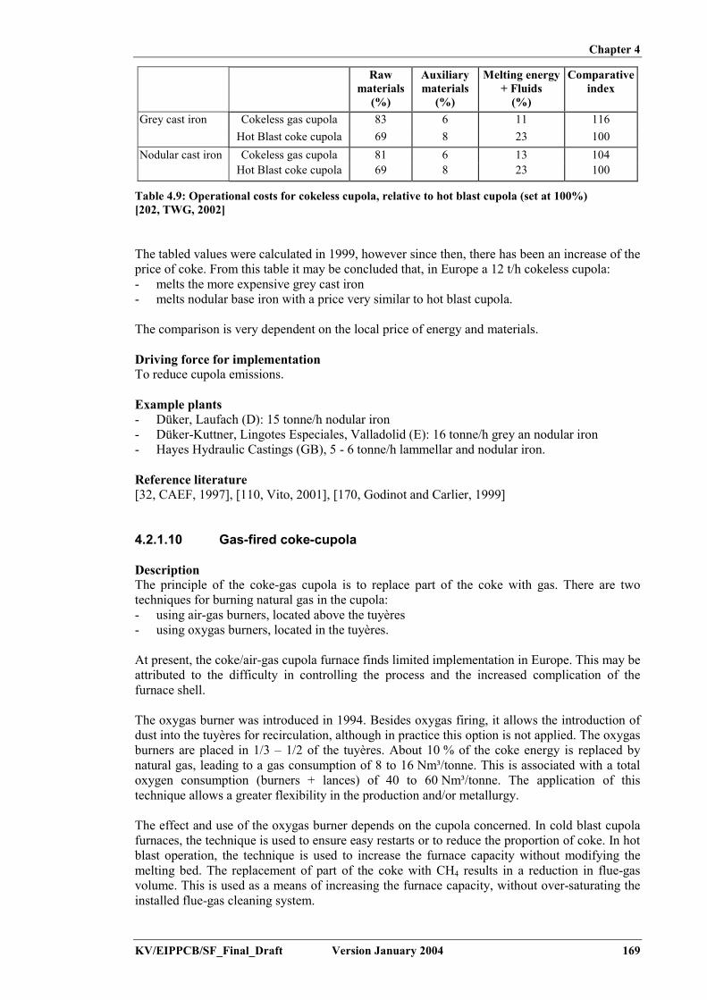
Chapter 4
KV/EIPPCB/SF_Final_Draft Version January 2004 169
Rawmaterials
(%)
Auxiliarymaterials
(%)
Melting energy+ Fluids
(%)
Comparativeindex
Grey cast iron Cokeless gas cupola 83 6 11 116Hot Blast coke cupola 69 8 23 100
Nodular cast iron Cokeless gas cupola 81 6 13 104Hot Blast coke cupola 69 8 23 100
Table 4.9: Operational costs for cokeless cupola, relative to hot blast cupola (set at 100%)[202, TWG, 2002]
The tabled values were calculated in 1999, however since then, there has been an increase of theprice of coke. From this table it may be concluded that, in Europe a 12 t/h cokeless cupola:- melts the more expensive grey cast iron- melts nodular base iron with a price very similar to hot blast cupola.
The comparison is very dependent on the local price of energy and materials.
Driving force for implementationTo reduce cupola emissions.
Example plants- Düker, Laufach (D): 15 tonne/h nodular iron- Düker-Kuttner, Lingotes Especiales, Valladolid (E): 16 tonne/h grey an nodular iron- Hayes Hydraulic Castings (GB), 5 - 6 tonne/h lammellar and nodular iron.
Reference literature[32, CAEF, 1997], [110, Vito, 2001], [170, Godinot and Carlier, 1999]
4.2.1.10 Gas-fired coke-cupola
DescriptionThe principle of the coke-gas cupola is to replace part of the coke with gas. There are twotechniques for burning natural gas in the cupola:- using air-gas burners, located above the tuyères- using oxygas burners, located in the tuyères.
At present, the coke/air-gas cupola furnace finds limited implementation in Europe. This may beattributed to the difficulty in controlling the process and the increased complication of thefurnace shell.
The oxygas burner was introduced in 1994. Besides oxygas firing, it allows the introduction ofdust into the tuyères for recirculation, although in practice this option is not applied. The oxygasburners are placed in 1/3 – 1/2 of the tuyères. About 10 % of the coke energy is replaced bynatural gas, leading to a gas consumption of 8 to 16 Nm³/tonne. This is associated with a totaloxygen consumption (burners + lances) of 40 to 60 Nm³/tonne. The application of thistechnique allows a greater flexibility in the production and/or metallurgy.
The effect and use of the oxygas burner depends on the cupola concerned. In cold blast cupolafurnaces, the technique is used to ensure easy restarts or to reduce the proportion of coke. In hotblast operation, the technique is used to increase the furnace capacity without modifying themelting bed. The replacement of part of the coke with CH4 results in a reduction in flue-gasvolume. This is used as a means of increasing the furnace capacity, without over-saturating theinstalled flue-gas cleaning system.

Chapter 4
170 Version January 2004 KV/EIPPCB/SF_Final_Draft
The technique results in an increase in the carbon content of the melt and allows an increase inthe amount of steel in the charge. The process provides a means of injecting FeSi, which is lessexpensive in powder form than as ore. These properties result in a beneficial economic effect.
Achieved environmental benefitsThe replacement of part of the coke with CH4 results in a reduction in the flue-gas volume. Inaddition, the flue-gas is made more combustible due to the higher CO and H2 contents. If postcombustion is present, the resulting flue-gases will show lower levels of organic compoundsand CO.
The replacement of coke by natural gas reduces the emission levels of SO2.
The technique allows the possibility of recirculating cupola dust into the melt. Although, aftersome initial trials, this application has not been fully developed.
Reducing the level of coke in the cupola increases the risk of bridging.
Cross-media effectsThe production, storage and use of oxygen increases the safety risks. Oxygen production is donethrough cryogenic distillation or Vacuum (Pressure) Swing Adsorption, which both involveelctricity consumption. The consumption of the latter technique is 0.35 – 0.38 kWh/Nm³ O2.Oxygen production is often done by an external supplier, who delivers the oxygen to a storagetank or directly through a pipeline.
Operational dataThe AGA-Rayburn Foundry (Coalbrookdale, UK) equipped 3 out of 8 tuyères of their cold blastcupola with oxygas burners. This allowed a reduction in the overall proportion of coke from15 % to 10 %. There was a resultant drop in the sulphur content of the produced iron, this thenallowing a reduction to be made in the amount of pig iron used, and thus yielding an economicgain.
Fritzwinter foundry (D) equipped 3 out of 6 tuyères of their 20 – 25 tonnes/h hot blast cupolawith oxygas burners. This allowed an increase in production capacity to 28 tonnes/h, withoutthe need to change the melting bed, nor the flue-gas cleaning system. The effect on the flue-gascomposition before burning is given in Table 4.10.
With oxygenwithout oxygas burners
With oxygenwith oxygas burners
H2 0.8 – 1.2 2.2 – 2.4CO 14 – 15 19O2 2 2
Table 4.10: Effect of oxygas burners on the flue-gas composition for a hot blast cupolavalues in %[184, Godinot and Ressent, 2002]
ApplicabilityThe technique may be applied on both cold blast and hot blast cupolas in both new and existinginstallations. The advantages drawn from the application (increased flexibility, economicalbenefit, reduced flue-gas volume, increased capacity) will depend on the specific meltingconditions of the installation under consideration. The technique has been reported to causedifficulties for controlling the process and also increases the complication of the furnace shellrequired.

Chapter 4
KV/EIPPCB/SF_Final_Draft Version January 2004 171
EconomicsOperational costs before and after switching a cold blast cupola to oxygas operation for theabove-mentioned Aga-Rayburn foundry (UK) are given in Table 4.11. Prices are forecasts ascalculated by CTIF (F).
Unit price Without burners With burnersInput Units
EURConsumption
per tonneCost
EUR/tonneConsumption
per tonneCost
EUR/tonneCoke Tonne 198 0.15 29.7 0.1 19.8Gas Nm³ 0.15 0 - 16.5 2.5Oxygen Nm³ 0.38 14 5.4
0.23 40 9.2Pig iron Tonne 164.6 0.2 32.9 0 -Scrap iron Tonne 125.8 0.2 37.7 0.5 62.9Total EUR/tonne 105.7 94.4All values per tonne molten metal
Table 4.11: Operational costs for cold blast cupola with and without oxygas burners[184, Godinot and Ressent, 2002]
Operational costs decrease from EUR 105/tonne to EUR 94/tonne molten metal. The economicgain can mainly be attributed to the reduced proportion of pig iron. This also stresses the factthat the balance will differ for each specific foundry.
Driving force for implementationTo increase flexibility of the foundry and/or to increase the production capacity of existinginstallations without changing the installation layout.
Example plants- AGA-Rayburn Foundry (Coalbrookdale, UK)- Fritzwinter foundry (D)
Reference literature[156, Godinot, 2001], [184, Godinot and Ressent, 2002]
4.2.2 Electric arc furnace
4.2.2.1 Shortening melting and treatment time
DescriptionImproved control methods can lead to shorter melting or treatment times. Some examples are:- closer control of the composition (e.g. C, S, P content) and the weight of the charged
materials and slag forming materials- reliable temperature control of the melt, this can improve the yield of the refining reactions
and avoid overheating- more efficient methods for sampling and deslagging, these can reduce furnace downtime.
Secondary metallurgy, using AOD/VODC treatment, shortens EAF time and has a positiveimpact on energy conservation. The technique is discussed further in Section 4.5.7.1.
Achieved environmental benefitsIncreased furnace efficiency through shorter melting times and reduced downtime.
Cross-media effectsNo cross-media effects apply.
ApplicabilityThis technique applies to all new and existing EAF furnaces.
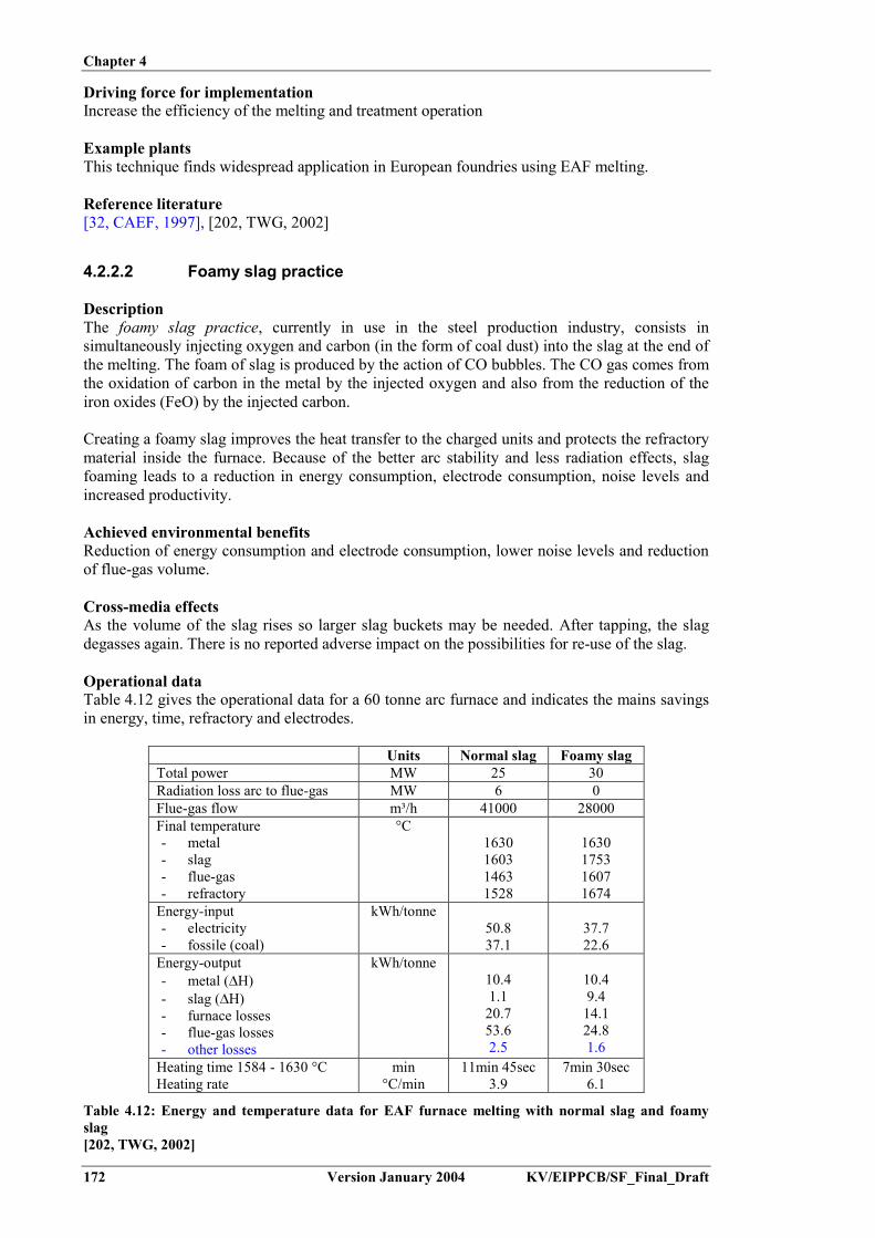
Chapter 4
172 Version January 2004 KV/EIPPCB/SF_Final_Draft
Driving force for implementationIncrease the efficiency of the melting and treatment operation
Example plantsThis technique finds widespread application in European foundries using EAF melting.
Reference literature[32, CAEF, 1997], [202, TWG, 2002]
4.2.2.2 Foamy slag practice
DescriptionThe foamy slag practice, currently in use in the steel production industry, consists insimultaneously injecting oxygen and carbon (in the form of coal dust) into the slag at the end ofthe melting. The foam of slag is produced by the action of CO bubbles. The CO gas comes fromthe oxidation of carbon in the metal by the injected oxygen and also from the reduction of theiron oxides (FeO) by the injected carbon.
Creating a foamy slag improves the heat transfer to the charged units and protects the refractorymaterial inside the furnace. Because of the better arc stability and less radiation effects, slagfoaming leads to a reduction in energy consumption, electrode consumption, noise levels andincreased productivity.
Achieved environmental benefitsReduction of energy consumption and electrode consumption, lower noise levels and reductionof flue-gas volume.
Cross-media effectsAs the volume of the slag rises so larger slag buckets may be needed. After tapping, the slagdegasses again. There is no reported adverse impact on the possibilities for re-use of the slag.
Operational dataTable 4.12 gives the operational data for a 60 tonne arc furnace and indicates the mains savingsin energy, time, refractory and electrodes.
Units Normal slag Foamy slagTotal power MW 25 30Radiation loss arc to flue-gas MW 6 0Flue-gas flow m³/h 41000 28000Final temperature- metal- slag- flue-gas- refractory
°C1630160314631528
1630175316071674
Energy-input- electricity- fossile (coal)
kWh/tonne50.837.1
37.722.6
Energy-output- metal (�H)- slag (�H)- furnace losses- flue-gas losses- other losses
kWh/tonne10.41.1
20.753.62.5
10.49.4
14.124.81.6
Heating time 1584 - 1630 °CHeating rate
min°C/min
11min 45sec3.9
7min 30sec6.1
Table 4.12: Energy and temperature data for EAF furnace melting with normal slag and foamyslag[202, TWG, 2002]

Chapter 4
KV/EIPPCB/SF_Final_Draft Version January 2004 173
Slag density is reduced from 2.3 tonne/m³ to 1.15 – 1.5 tonne/m³.
ApplicabilityThis technique applies to new and existing EAF foundries that practice oxygen injection.
Driving force for implementationIncreasing the efficiency of furnace operation.
Example plantsNo specific example plants were reported, but the technique finds application in severalEuropean foundries.
Reference literature[32, CAEF, 1997], [202, TWG, 2002], [211, European IPPC Bureau, 2000]
4.2.3 Induction furnace
4.2.3.1 Process optimisation: optimising charge materials, charging andoperation
DescriptionProcess optimisation options for coreless induction furnaces include:- Optimise feedstock condition: This involves avoiding rusty and dirty inputs, utilising
optimum size and density input/scrap, and using cleaner carburisers. These measuresshorten the melting time, reduce the specific energy needed for melting and/or reduce theamount of slag formed
- Close furnace lid: Oxidation is reduced by avoiding badly fitting lids andunnecessary/prolonged openings, by quick charging, or by using a protective atmosphereover the melt (N2). Opening times need to be minimised to prevent energy losses. Thenecessary opening times for charging, removing slag, temperature measuring, sampling andpouring vary between 50 % and 25 % of the shift time. The latter figure applies for newfurnaces, working in optimised conditions. A well-fitted closed lid limits the surface heatloss to about 1 % of the input power. When open, the heat loss can amount to up to 130kWh/tonne for a 10 tonne capacity unit. When melting under a closed lid, care should betaken not to overheat the furnace
- Restrict holding to a minimum: Since melting is the first step in the foundry process chain, ashortening of the holding time can only be obtained by an integrated process optimisationfor the whole foundry process and by minimising delays, problems and irregularities in anyof the foundry departments. During holding, composition adjustment is performed based onthe results of an analysis made on a chill cast sample. Optimisation of the sampling, testingand adjusting procedures is another measure for reducing the holding time
- Operate at maximum power input level: Furnaces are more efficient in their use of energywhen they are being operated at maximum power input levels, and best results are obtainedwhen the available power can be fully utilised for the largest proportion of the meltingcycle. This also includes reducing cold start melts (optimise production programme), andallowing follow-up using monitoring and computer control
- Avoid excessive temperature and unnecessary superheating: It is important that the metalreaches the required temperature just at the time that the moulding department is in aposition to receive it. Good co-operation between the melting and moulding shop isessential in order to minimise the electricity usage
- Optimise high temperature melts for slag removal (good balance): Low melting point slagbuild-up can be reduced by heating the furnace up to elevated temperatures (1580 ºC vs.1450 ºC normal). This results in a higher energy consumption, and can affect themetallurgical aspects of the melt. If the slag is allowed to build up on the furnace lining, thiscan affect the electrical efficiency of the furnace. Slag removal requires the opening of thefurnace lid, and thus causes a thermal loss. A good balance needs to be found betweenincreasing the melt temperature and the slag removal practice

Chapter 4
174 Version January 2004 KV/EIPPCB/SF_Final_Draft
- Prevent slag build up: More common and more troublesome are instances where highmelting point build-up is involved. This mainly results from charging sand and, in the caseof iron melting, metallic aluminium into the melt. Some furnace operators have attemptedflux additions and cleaning routines but prevention is better than cure in this respect. Thisinvolves minimising the presence of sand and Al in the raw materials
- Trickle the oxygen injection: Instead of using conventional decarburisation- Minimise and control the refractory wall wearing: The refractory life depends on the choice
of materials as a function of the slag chemistry (acidic or basic), the operational temperature(steel, cast iron, non-ferrous), and the care taken upon relining (sintering). The lifetime mayvary from 50 (steel, cast iron) to 200 – 300 (cast iron) melts. Operational control measuresare taken to follow the refractory wear. These include visual inspection, physicalmeasurement and instrumental monitoring programmes. Good charging practice measuresprevent the cumulative effects of physical chokes and mechanical stresses. These includethe use of automatic charging systems, hot charging, avoiding high drops and the use ofcompact and dry scrap.
Achieved environmental benefitsIncreased furnace efficiency through shorter melting times and reduced downtime.
Cross-media effectsNo cross-media effects apply.
Operational dataA typical coreless furnace can melt a tonne of iron and raise the temperature of the liquid metalto 1450 ºC using under 600 kWh of electricity. However, in practice, only a few foundries canachieve this level of specific consumption on a week-by-week basis. Some foundries consumein the region of 1000 kWh for every tonne of iron produced by their coreless furnaces.Prevailing circumstances in many foundries can restrict the scope for good energy management,but in fact almost all coreless melting operations could be improved in some way, in order toachieve a worthwhile saving in the quantity of electricity used per tonne of iron processed.
ApplicabilityThis technique applies to all new and existing induction furnaces.
Driving force for implementationIncreasing the efficiency of furnace operation.
Example plantsProcess optimisation measures are commonly applied in European foundries using inductionfurnaces.
Reference literature[32, CAEF, 1997], [47, ETSU, 1992], [110, Vito, 2001], [145, Inductotherm], [225, TWG,2003]
4.2.3.2 Change from mains frequency to medium frequency furnaces
DescriptionMedium frequency (250 Hz) furnaces have a higher power density (up to 1000 kW/tonne) thanmains frequency (50 Hz) furnaces (300 kW/tonne). This allows the use of a smaller crucible (upto a factor of three smaller) which results in a smaller total heat loss. The thermal efficiency ofmedium frequency furnaces is 10 % higher than for the mains frequency types. Additionally,mains frequency units need to be operated with a molten heel of up to 2/3 of the cruciblecapacity to optimise specific energy consumption and also require specific starter-blocks forcold start-up. Medium frequency furnaces can readily be started with a cold charge and can beemptied at the end of each working shift or melting batch.
Chapter 4
KV/EIPPCB/SF_Final_Draft Version January 2004 175
When a foundry converts from mains frequency melting to operating a medium frequencyinstallation, it is important that the furnace personnel undertake some retraining. Operatingtechniques formally used to date will have to be abandoned, and new specific proceduresdesigned to give good specific energy consumption will have to be adapted. If retraining isoverlooked, the available improvements in energy usage may not be fully realised.
Achieved environmental benefitsIncreased energy efficiency of the melting operation.
Cross-media effectsNo cross-media effects apply.
Operational dataOperational data are given in Section 3.2.4.
ApplicabilityThis technique applies to new installations and for major refurbishments of existing installations
Driving force for implementationTo increase the efficiency of the foundry operation.
Example plantsThe technique is commonly applied in foundries installing a new furnace.
Reference literature[47, ETSU, 1992]
4.2.4 Rotary furnace
4.2.4.1 Increasing the furnace efficiency
DescriptionAll measures that increase the thermal efficiency of the furnace will in turn lead to a lower CO2output. A major improvement has been achieved by introducing oxygen instead of air as thecombustion medium. This is discussed in Section 4.2.4.2.
Further improvements of furnace yield can be obtained through tight control and optimisationof:- burner regime- burner position- charging- metal composition- temperature.
Achieved environmental benefitsThe optimisation results in lower amounts of dust and residues and in higher energeticefficiency.
Cross-media effectsNo cross-media effect apply.
Operational dataAn optimisation programme on a 3 tonnes/h cast iron melting furnace suggested the followingas good operational practice:

Chapter 4
176 Version January 2004 KV/EIPPCB/SF_Final_Draft
- use of clean scrap and loading in the following order: (1) ingots and materials with low Si-content; (2) internal return material and foundry scrap; (3) alloying elements and meltprotection; (4) steel scrap
- melt protection: use of anthracite for melt protection (2 % of metal charge) and silicon(2 %)
- rotation: in discontinuous phase, 1/3 of a rotation every minute with a total of 7.5 turns untilthe phase change. During continuous rotation: 1.7 rotations/minute
- power and angle of burner: use a parallel burner-head position for the lower injectors. Startat maximum power during 20 minutes, reducing 10 % every 20 minutes until change ofphase (60 minutes after start).
Using these measures, a metal efficiency (molten metal/charged metal) at >95 % could bemaintained.
ApplicabilityThe principles of the optimisation are generally valid for iron melting in rotary furnaces usingoxygen burners. The operational data have been established for a 3 tonnes/h furnace. Forfurnaces of other sizes, a site-specific optimisation is necessary.
Driving force for implementationOptimisation of furnace operation and to increase the melting efficiency.
Example plantsProcess optimisation measures are commonly applied in European foundries using rotaryfurnaces.
Reference literature[204, Carnicer Alfonso, 2001]
4.2.4.2 Use of an oxyburner
DescriptionFlame temperatures are increased by the application of pure oxygen instead of air in the burnersused for melting or preheating the pouring ladles. This enables a more efficient heat transfer tothe melt and reduces the energy use.
If the air supply is blocked by a tight closure of the recipient, no NOx can be formed through theoxidation of atmospheric nitrogen. Additionally, the total flow of flue-gases from an oxyburneris smaller due to the absence of nitrogen ballast. This allows the application of a smallerdedusting installation.
Achieved environmental benefitsThe techniques reduce energy consumption and lower the emissions of NOx and CO2, throughhigher combustion temperatures.
Cross-media effectsThe production, storage and use of oxygen increases the safety risks. Oxygen production is donethrough cryogenic distillation or Vacuum (Pressure) Swing Adsorption, which both involveelectricity consumption. The consumption of the latter technique is 0.35 – 0.38 kWh/Nm³ O2.Oxygen production is often done by an external supplier, who deliver the oxygen to a storagetank or directly through a pipeline.
Fuel or heavy oil gives rise to SO2 or NOx emissions, depending on their S or N content. The useof cleaner carburants such as natural gas and propane will not cause any additional pollution,except for CO2, as is the case for all combustion processes.

Chapter 4
KV/EIPPCB/SF_Final_Draft Version January 2004 177
Operational dataTable 4.13 gives, for the "oxygas" melting of cast iron and various furnace capacities, thetheoretical consumption of several fuels and of oxygen per tonne melted:
Energy source Units Furnace capacity (tonnes)3 5 8 12 20
Light fuel oil kg/tonne 33 – 38 33 – 38 33 – 38 32 – 37 32 – 37Natural gas Nm3/tonne 38 – 43 38 – 43 38 – 43 38 – 42 38 – 42Propane Nm3/tonne 15 – 17 15 – 17 15 – 17 14 – 16 14 – 16Oxygen Nm3/tonne 130 – 150 130 – 150 130 – 150 130 – 145 130 – 145
Table 4.13: Table of energy consumptions (minimum melt)[148, Eurofine, 2002]
Oxygen enrichment used in conjunction with a recuperator generally achieves a 30 % energysaving. Additionally, the higher combustion temperature assists in reducing the overallemissions. The exhaust gas volume is also reduced. Full oxy/fuel firing may offer energysavings of up to 50 %, and can reduce the exhaust gas volume by up to 72 %.
A German installation’s change from oil-air firing to gas-oxygen firing caused a reduction innoise emissions of 15 – 18 dB(A) in the immediate vicinity of the furnace, dependent on thepoint of analysis. At the installation border, a value of 48 dB(A) was measured. With theapplication of energy recuperation for charge preheating, a total energy saving of 53 % wasreported.
ApplicabilityThis technique can be applied on any rotary furnace and in the preheating of pouring ladles.Oxyburners do not find implementation in non-ferrous foundries, although they are used e.g. insecondary copper smelting.
EconomicsInvestment costs: EUR 3400 – 4500.Operational costs: dependent on process operation.
Driving force for implementationOptimisation of furnace operation and to increase melting efficiency.
Example plantsThis technique finds wide application in ferrous foundries using rotary furnaces.
Reference literature[23, Brettschneider and Vennebusch, 1992], [32, CAEF, 1997], [110, Vito, 2001], [103,Vereniging van Nederlandse Gemeenten, 1998], [148, Eurofine, 2002], [163, UK EnvironmentAgency, 2002], [232, Novem, 2000]
4.2.5 Selection of cupola vs. induction or rotary furnace for cast ironmelting
DescriptionGiven the fact that various melting techniques show overlapping fields of application, a basictechnique is the selection of the melting technology. In this selection the decisive criteriainclude:

Chapter 4
178 Version January 2004 KV/EIPPCB/SF_Final_Draft
- metal type- continuous or batch production- size of the series- metal throughput or capacity- flexibility towards input material type and cleanliness- flexibility towards alloy change- type of product made- emissions and other environmental considerations- availability of raw materials- availability of fuels/electricity.
The application of the different melting techniques is very dependent on the indicated criteria.From the discussions mentioned above, the following generalities can be deduced:
- Metal type: Electrical furnace better placed for nodular or alloyed cast iron- Continuous production: Cupola is better placed- Batch production: Electrical or rotary furnace is better placed- Flexibility towards input material type and cleanliness: Cupola is better placed- Flexibility towards alloy change: Induction and rotary furnace is better placed- Environmental considerations:
� cupola is better placed only if well de-dusted, cokeless show better environmentalperformance than HBC or CBC
� induction has lower CO, SO2, NOx, dioxin, slag, but this it needs to be borne in mindthere will also be emissions from the required electricity production.
- Availability ofraw materials: When cheap scrap is available, the cupola is better placed
In fact, all these criteria must be considered together. Table 4.14 gives a summary, based on thetechnical considerations. Economic data for the various cupola types and the induction furnaceare given in Annex 1.
On the basis of the stated criteria, the replacement of the cupola by induction or rotary furnacesmay be considered. The selection of induction or rotary furnaces is given priority over cold blastcupolas for small foundries casting a variety of products in several European countries (e.g.Austria, Belgium (Flanders)).

Chapter 4
KV/EIPPCB/SF_Draft_2 Version January 2004 179
CRITERION ONLY GREY CAST IRON GREY +NODULAR
ONLY NODULAR CAST IRON ONLYMALLEABLECAST IRON
Type of productmade
Counterweights
Sewer castings,pipes, urban
furniture
Enameledcastings,heating
appliances
Mechanical parts Mechanicalparts
Sewercastings,
pipes, urbanfurniture
Mechanical parts Mechanicalparts
Size of series Medium tolarge
All Medium tolarge
Batch tosmall
Mediumto large
All All Batch tosmall
Medium tolarge
Medium tolarge
Cupola Coldblast
++ ++(<10 - 15 t/h)
++(<10 - 15 t/h)
++(<10 - 15 t/h)
(+)
Hotblast
+ ++(>10 - 15 t/h)
++(>10 - 15 t/h)
0 ++(>10 - 15 t/h)
++(>10 - 15 t/h)
0 +(>10 - 15 t/h)
Cokeless 0 + + 0 +Induction + + ++ ++ ++ + ++ ++ ++Rotary furnace (+) batch ++ + ++ (+) batch or
small series ++ ++
++: technically more adapted;+: technically adapted(+): adapted in some cases0: not adapted
Table 4.14: Technical choice of the melting equipment for cast iron melting[202, TWG, 2002]

Chapter 4
180 Version January 2004 KV/EIPPCB/SF_Final_Draft
Achieved environmental benefitsReplacement of a cupola by an induction or rotary furnace results in a reduction in the directemissions of CO and SO2 and a reduced amount of slag. Induction furnaces show a reducedemission of NOx and a lower risk of dioxin formation. The indirect emissions generated by theuse of induction furnaces, depend on the local electricity generation infrastructure.
Cross-media effectsReplacement of a cupola by an induction furnace generates a strong increase in electricityconsumption.
ApplicabilityThe replacement of a cold blast cupola by an induction or rotary furnace is applicable under thecriteria stated above and upon major refurbishment of the installation.
For new installations, the criteria of Table 4.14, apply besides local and site-specificconsiderations. If cupola and induction or rotary furnaces are indicated as most adapted, theinduction and rotary types may be preferred on the basis of their environmental benefits.
EconomicsA survey of economic data for the various types of cupola furnaces and for the inductionfurnace is given in Annex 1.
In Table 4.15, a summary is given of cost data collected by an example Spanish foundry thatwanted to replace an existing cupola by a rotary or electric furnace. No emission collection orfiltration equipment costs are included. Data are from 1997 - 1998. The comparison involves thefollowing three systems:- cold blast cupola: 3.5 tonne/h capacity- oxygas rotary furnace: 3 tonne capacity- 2 medium frequency induction furnaces: 2 + 1 tonne capacity.
The cost calculation was performed for melting costs for a melting production of 1 tonne/h,working 8 hours/day. For the induction furnace a distinction is made between peak-timeelectricity costs and off-peak-time. Since electricity is the major component of the costs, thisdistinction makes a big difference to the final cost. Operation of the induction furnace duringoff-peak time (night-time) results in costs comparable to rotary furnace costs. The data showthat the investment has a 5 – 9 years payback period.
Costs in EUR/tonne ofmolten metal
Cupola Rotary Induction
Energy 30.7 29.8 40.8 (peak)27.2 (valley)
Refractory 3.6 1.3 1.4Man power 52.9 22.7 22.7Raw materials 205 205 205Total cost 292 259 270Yearly costs in EURCost for melting1320 tonne/year 385000 341000 356000 (peak)
338000 (valley)Savings none 44000 29000 (peak)
47000 (valley)Investment none 250000 260000
Building Not needed Needed
Table 4.15: Example plant cost data for replacement of an existing cupola with a rotary orinduction furnaceData from 1997 - 1998, Spain[202, TWG, 2002]

Chapter 4
KV/EIPPCB/SF_Final_Draft Version January 2004 181
Driving force for implementationReduction of direct emissions from cast iron melting.
Example plantsMost Austrian foundries, which are small and medium-sized enterprises, have changed fromcupola melting to induction furnaces. As a consequence there are only three Austrian foundriesleft which still use cupola melting.
Reference literature[202, TWG, 2002], [110, Vito, 2001], [225, TWG, 2003]
4.2.6 Hearth type furnace
4.2.6.1 Use of an oxyburner
See Section 4.2.4.2.
4.2.7 Other furnace types
4.2.7.1 Alternatives to the use of SF6 as a cover gas for Mg-melting
DescriptionAlternative covering gases for magnesium melting are of big interest due to the high globalwarming potential of the generally used SF6. The substitution of SF6 has been the topic ofresearch for several years. A worldwide research project to develop and propose alternatives iscurrently being co-ordinated by the International Magnesium Association and will be finalisedin 2004. Gas mixtures containing HFC-134a and Novec612 (perfluoroketone) have beensuccessfully tested. These compounds, however, also show a high global warming potential andfall under the restrictions of the Kyoto protocol.
At present, SO2 is a viable alternative. Some magnesium foundries have long experience withthis gas, and never turned to SF6 when this gas was first introduced at the beginning of the1970s. SO2 reacts with liquid magnesium and builds a protective film on the surface. A mixingunit for blending a low concentration SO2-air mixture is available. Furthermore, handlingprocedures for SO2 have been established to reduce workers exposure and risk.
The protective gas is supplied through a manifold with several outlets. The positions of theoutlets are chosen to give protection to all areas of the metal surface. Areas closer to hatchesthat will be opened frequently during operation need a higher flow of gas than areas whereinteraction with the surrounding atmosphere is small.
In order to optimise safety and minimise gas consumption, totally encapsulated melting andcasting processes are applied.
If replacement is not feasible, the following technical measures allow a reduction of SF6consumption and emissions:- improved sealing of furnaces- fully automatic cover gas dosage- electronic control of both gas mix and flowrate- reduction of overdosing.
Achieved environmental benefitsThe replacement of SF6 avoids using this greenhouse gas, which has a GWP of 22200 over a100 years time horizon.
Cross-media effectsSO2 is a toxic gas and exposure limit values for workers should be taken into account. Theoccupational exposure limit in most countries is 2 ppm (5 mg/m³) over 8 hours. Sulphur- and

Chapter 4
182 Version January 2004 KV/EIPPCB/SF_Final_Draft
oxygen-containing deposits may form on the furnace wall. Under unfavourable conditions thesedeposits can be immersed into the molten metal where they cause reactions leading to metaleruptions from the surface. Frequent removal of scaling can prevent this from happening.
The technique results in emissions of small amounts of SO2, the amount depending on thefoundry capacity and the number of furnaces. One estimate could be 50 – 500 kg per year formelt protection.
Operational dataThe consumption of SF6 depends on the melting technique used, and varies between less than0.1 and 11 kg/tonne of finished castings. Technical improvements and measures have resulted ina reduction in the average specific SF6 consumption, from over 3 kg/tonne of casting to 0.9kg/tonne. Application data are given in Section 3.4.1.
In an undisturbed melt, the use of SO2 would be typically 0.7 % in air at a flowrate of 5 to10 litre/minute. In closed (but not airtight) furnaces, such as the melting and dosing furnaces ofdie-casting machines, pure SO2 is applied. Small amounts of air entering through the lid areneeded to provide the covering action. If a carrier gas is used, nitrogen is the preferred gasbecause of its inertness. The SO2 is then mixed in concentrations of 1 – 2 %.
Mass balance data for the fluxless re-melting of magnesium scrap are given in Section 4.1.6.
ApplicabilityThere is a great potential to reduce the SF6 consumption, but at the moment it does not seempossible to fully replace it during non-standard situations. SO2 may be applied in general duringnormal melting operations. When repairing the furnace, SF6 remains needed as a protection gas,due to the health risks correlated with SO2 exposure. Additionally, SO2 cannot be used toextinguish magnesium fires. In this case also, SF6 remains in use.
EconomicsThe price of SF6 has increased dramatically over the last few years. Conversion from SF6 to SO2will therefore have an associated economic cost. Table 4.16 gives estimates for the runningexpenses for the use of SF6 and SO2 based on information from a die-caster running three die-casting machines and the results from industrial scale trials. Even though the figures are onlyrough estimates, they clearly show that there is a large cost saving potential when substitutingSO2 for SF6.
Property Units SF6 SO2
Concentration of gas % 0.4 0.7Price EUR/kg 36.5 4.5Inverted density (at 0 ºC and 1 atm) l/kg 153 350Yearly consumption of gas kg/yr 339 259Cost/year EUR 12373 1165Data for 3 die-casting machines, run at 300 days/yr, 24 h/day with flowrate of gas to eachmachine of 10 l/min
Table 4.16: Cost comparison between SO2 and SF6 used for protective gas atmospheres[190, Schubert and Gjestland]
If a new investment is considered, the SO2 gas system, meeting all modern safety and dosagerequirements, costs EUR 70000, for a 1000 tonnes/yr plant. A new SF6 system costsEUR 23300. Operational data, accounting for this investment and for the use of 1.5 % of SO2and 0.2 % of SF6, both in nitrogen, are given in Table 4.17. The total annual cost for SO2 issome EUR 2500 more than for SF6, on the other hand 12300 tonnes of CO2 equivalentemissions are avoided. The bigger the plant, the less the annual costs differ between the twosystems. At an annual output of 1500 tonne/yr, the turning-point is passed and the CO2reduction cost turns negative.

Chapter 4
KV/EIPPCB/SF_Final_Draft Version January 2004 183
General Casting DataCapacity of the ovens 2000 kgMaximum smelting performance 1000 kg/hCasting time per day (Cold chamber) 13.2 hWorking days 250/yrUtilisation 76 %Gross melting weight (shot weight) 2000 t/yrScrap factor 50 %Net weight of the Mg parts 1000 t/yrSales per year (EUR 15.00/kg) EUR 15 millionSurface of the Mg baths 6 m3
Gas (carrier + cover gas) per m2 surface 300 litres per hour, all year longExtra gas dosage while charging + 25 %Gas Data SF6 SO2Carrier gas nitrogen nitrogenCover gas concentration in carrier gas 0.2 vol. % 1.5 vol. %Cover gas dosage per hour 46.9 g 154.2 gCover gas dosage per year 514 kg 1688 kgCoefficient cover gas/net Mg output 0.51 kg/t 1.69 kg/tEmissions in tonnes CO2 equivalent 12278 -Cost Data SF6 SO21 kg cover gas EUR 20.00 EUR 3.001 m3 carrier gas (nitrogen) EUR 0.20 EUR 0.20Invest-cost of new gas equipment EUR 23333 EUR 70000Discount rate per year 10 % 10 %Depreciation period 10 yr 10 yrAnnualised invest cost of equipment EUR 3797 EUR 11392Operating cost of cover gas EUR 10274 EUR 5065Annual running cost (without nitrogen) EUR 14072 EUR 16457Additional total cost of using SO2 - EUR 2385Specific emissions reduction cost - EUR 0.19/tonne CO2 eq.Share of additional cost in sales 0.02 %Note: Most data are valid only for this 1000 tonne/yr plant and will change with plant size
Table 4.17: Operational and cost data for a new die-casting plant of 1000 tonne/yr Mg output[218, Harnisch and Schwarz, 2003]
For existing installations, the reduced cost for SO2 consumption needs to pay back theinvestment cost for the conversion of the cover gas installation. The payback time is dependenton the actual cover gas consumption. Based on an SF6 consumption of 0.9 kg/tonne, the turningpoint at which the total costs of using SO2 get lower than the comparable cost of SF6 is below900 tonne/yr output. At 500 tonnes/yr the SO2 is still more expensive, but the specific reductioncost of 1 tonne CO2 eq. amounts to EUR 0.31. The share of additional costs in the plants salesamounts to 0.04 %. Therefore at this capacity, the technique can also be considered.
As a conclusion, it is found to be economic to use SO2 instead of SF6 as a cover gas inmagnesium die-casting, at least in plants with an annual metal output of 500 tonnes and more,regardless of whether the plant is to be newly built or still runs with SF6.
Driving force for implementationReduction measures for greenhouse gas emissions, in particular, the Kyoto climate protocolcontrolling the use of fluorinated gases: HFCs, PFCs and SF6. These gases have a high globalwarming potential but are not ozone depletors. This will form the basis for the EU Directive onthe use of fluorinated gases. Furthermore, some regions have already issued proposals to ban itsuse, such as e.g. Denmark, Germany and Austria.
Example plantsLM Leichtmetall Systemtechnik, Felbach (D)In Austria, Denmark and Sweden SF6 is no longer used as a cover gas.

Chapter 4
184 Version January 2004 KV/EIPPCB/SF_Final_Draft
Reference literature[182, Closset, 2002], [190, Schubert and Gjestland], [191, IMA, et al.], [192, Gjestland andWestengen, 1996], [194, UNEP IPCC, 2002], [218, Harnisch and Schwarz, 2003]
4.2.8 Non-ferrous metal treatment
4.2.8.1 Aluminium degassing and cleaning using an impeller station
DescriptionThe degassing of aluminium is needed to remove hydrogen from the melt. The removal orreduction of small amounts of undesirable elements and impurities necessitates treatment of themelt with halogens, such as chlorine, fluorine or bromine. This treatment is referred to ascleaning, and is usually combined with the degassing treatment.
Adequate degassing with physically operating treatment processes does not achieve sufficientcleaning in most aluminium castings. Vacuum degassing achieves a very low hydrogen contentin the melt but, at the same time, the lower number of nuclei means that crystallisation is lesseffective.
In a combined degassing and cleaning process, gas mixtures of argon and chlorine or nitrogenand chlorine are introduced into the melt. The chlorine concentration in the carrier gas must beoptimised in order to ensure good cleaning as well as low emissions. In most cases, only adegassing treatment is necessary. This treatment is done without Cl2-gas. Depending on thetreatment vessel, the efficiency of the degassing can be improved with porous plugs andimpellers.
In some isolated cases, an Ar/SF6-mixture has been used. The latter is a greenhouse gas with ahigh global warming potential, which falls under the Kyoto protocol. (see also Section 4.2.7.1)
Achieved environmental benefitsThe use of an impeller with Ar/Cl2 or N2/Cl2 avoids the use of hexachloroethane in the cleaningtreatment of aluminium. The use of hexachloroethane was banned from 30 June 2003 in the EU.
Cross-media effectsThe application of this type of degassing unit has allowed an end to using hexachloroethane fordegassing and cleaning purposes.
Operational dataA mixture of nitrogen with 3 % Cl2 is generally used for combined degassing and cleaning. Fordegassing only, Cl2 is not necessary.
A mobile impeller station can be used for holding furnaces and ladles of 50 – 250 kg of Al. Thetreatment takes 3 to 5 minutes. A metal treatment unit is used for capacities from 400 to 1000 kgAl. The melt is treated for 1.5 to 5 minutes with a gas flow between 8 and 20 litre/minute. Thegraphite rotor has a life of 100 – 150 treatments, depending on the temperature of the melt.
ApplicabilityImpeller stations have been developed for holding furnaces and ladles from 50 to 1000 kg ofmolten aluminium.
EconomicsInvestment costs are given Table 4.18.
Description Cost (EUR)Impeller plant including accessories 15000Facilities for mixing of argon gas with chlorine 40000Total 55000
Table 4.18: Investment costs for an impeller station[178, Wenk, 1995]

Chapter 4
KV/EIPPCB/SF_Final_Draft Version January 2004 185
Driving force for implementationEuropean Directive 97/16/EC prohibiting the use of hexachloroethane in the manufacturing orprocessing of non-ferrous metals.
Example plantsThe technique is commonly applied in aluminium foundries.
Reference literature[175, Brown, 1999], [178, Wenk, 1995],
4.3 Mould- and core-making, including sand preparation
4.3.1 Selection of the mould type
The selection of the mould type is mainly based on technical criteria. The applicability of thevarious moulding types is summarised in Table 4.19. Additionally, Table 4.20 gives the generalproperties of various systems.
Lost moulds Permanent mouldsMoulding methods Casting technique
Gre
en sa
nd m
ould
ing
She
ll sa
nd
Phe
nol/F
uran
Pep
set/w
ater
gla
ss
Low
-pre
ssur
e di
e-ca
stin
g
Pre
ssur
e di
e-ca
stin
g (h
ot)
Pre
ssur
e di
e-ca
stin
g (c
old)
Cen
trifu
gal c
astin
g
Con
tinuo
us c
astin
g
Cast IronGrey cast iron X X X X O X XNodular cast iron X X X X X XMalleable cast iron X O X OWhite cast iron X X X
SteelUnalloyed X X X X XLow alloy steel X X X X XHighly alloyedmanganese steel X X X X X
Stainless and heatresistant X X X X O X
Heavy MetalsBrass X X X X XBronze X X X XCopper X X X X X X X XZinc alloys O X X
Light AlloysAluminium alloys X X X X X X XMagnesium alloys X O X X X X XTitanium O O X X O
X: The method can be usedO: The method is possible but not often employed
Table 4.19: Applicability of the various moulding types[126, Teknologisk, 2000]

Chapter 4
186 Version January 2004 KV/EIPPCB/SF_Final_Draft
Green sandcasting
Chemically-bonded sand
Low-pressure andgravity die-casting
High-pressuredie-casting
Relative cost in quantity Low Medium high Low Lowest
Relative cost for smallnumber
Lowest Medium high High Highest
Permissible weight ofcasting
Up to about 1tonne
Up to a fewhundred tonnes
50 kg 30 kg
Thinnest section castable,centimetres
0.25 0.25 0.3 0.08
Typical dimensionaltolerance, centimetres(not including partinglines)
0.03 0.02 0.07 0.02
Relative surface finish Fair to good Fair to good Good Best
Relative mechanicalproperties
Good* Good* Good* Best
Relative ease of castingcomplex design
Fair to good Good Fair Good
Relative ease of changingdesign in production
Best Fair Low Lowest
Range of alloys that canbe cast
Unlimited Unlimited Copper base andlower melting pointmetals preferable
Aluminium baseand lower melting
preferable(*) Mechanical properties may be enhanced by heat treatment
Table 4.20: Technical properties of the various moulding types[42, US EPA, 1998]
4.3.2 Moulding with clay-bonded sand (green sand moulding)
4.3.2.1 Preparation of clay-bonded sand by vacuum mixing and cooling
DescriptionThe mixing and cooling process are combined into a single process step. This is achieved byoperating the sand mixer under reduced pressure, which results in cooling by the controlledvaporisation of the water. The special mixer needs to be hermetically closed. It has a pressurecasing and is connected to a vacuum system. The layout of the system is given in Figure 4.6.

Chapter 4
KV/EIPPCB/SF_Final_Draft Version January 2004 187
Figure 4.6: Moulding-sand preparation plant with vacuum mixer-cooler[207, Drews, 1996]
As compared to a normal mixing plant (Figure 2.28), this technique does not require a separatecooler and associated equipment. The vacuum plant therefore is a more compact size. Since thetotal airflow is reduced, the vacuum installation has a smaller central dust extraction filter. Thesize and energy consumption of the filter are 50 % of that of a conventional plant. The reductionof the airflow, results in a reduced removal of active bentonite and thus in an overall reductionof additive consumption. Due to the enclosed operation, the technique is not affected by outsideclimatic conditions.
The use of steam in the absence of air leads to a quick activation of the bentonite, resulting in avery quick attainment of the optimal compressive strength for the bonded sand.
Water is added in two separate stages:- water to moisten the return sand to the prepared sand moisture content- water to cool the sand by vaporisation to the required temperature of 38 – 40 ºC.
The disadvantage of the system is the operation and management of the vacuum system. Theprocess also affects the sand technical properties (e.g. compressive and tensile strength,permeability), which diminish after 72h (“the 72h effect”). This can be prevented by re-mixingfor about 90s.
Achieved environmental benefitsReduction of the total airflow results in a reduced off-gas volume and amount of dust fordisposal, as well as a reduced consumption of binder as compared to conventional cooling andmixing plants (although this also depends on the efficiency of the regeneration plant).Additionally, the system uses less energy.
Cross-media effectsNo cross-media effects apply.

Chapter 4
188 Version January 2004 KV/EIPPCB/SF_Final_Draft
ApplicabilityThe technique is applicable in new green sand installations.
EconomicsThe commercial limits of application appear to be processes where sand cooling is required andwhich have a capacity of >60 tonnes of sand per hour.
Driving force for implementationReduction of dust for disposal and minimisation of additives consumption. Limitation of space.
Example plantsIn Japan, a vacuum mixing and cooling plant has been in operation since 1993, with a preparedsand throughput of 100 m³/h.Various installations are also currently running in Italy, France, Germany and England.
Reference literature[143, Inasmet and CTIF, 2002], [207, Drews, 1996], [214, Gerl, 2003]
4.3.3 Moulding and core-making with chemically-bonded sand
4.3.3.1 Minimisation of binder and resin consumption
DescriptionThe minimisation of chemicals consumption can be achieved through optimisation of theprocess controls and material handling. The latter category is dealt with in Section 4.1. In thissection process measures are discussed.
Overuse to compensate for poor process control is the most common way in which binderchemicals are wasted. For instance, key parameters that relate to good binder managementinclude:- Sand consistency: Use of a sand quality which is consistent with the binder system. Good
management of sand storage and sand testing (purity, grain size, shape, moisture) are of themain importance. A low content of fines and maximum amount of re-used sand will reducethe amount of resin needed
- Temperature control: The sand temperature must be maintained in a narrow range, withregular checks and adjustment of the amount of hardener addition. Positioning the sandheater just before the mixer allows close temperature control
- Mixer maintenance and cleaning- Mould quality: Checking, solving and preventing moulding defects- Addition rates: The appropriate binder addition depends on the binder type, the surface area
of the sand and the size of the casting- Mixer operation: Optimisation of the mixer performance involves monitoring and control of
its operation.
Table 4.21 lists the mixing process variables that are easy to measure using readily availableinstrumentation. Interfacing the controls with an alarm system allows the operator to be alertedto any ‘out-of-specification’ condition. This needs to be corrected by cleaning, maintenance andrecalibration before a major problem develops.

Chapter 4
KV/EIPPCB/SF_Final_Draft Version January 2004 189
Process variables Comments InstrumentationSand flow Can vary as a result of obstructions
at the discharge gate thatreduce/stop the sand flow orworn/loose stop nuts that produce afaster flow
Impact plate flowmeters
Sand temperature Determines the speed of hardeningand the amount/type of hardenerrequired
A process control instrument canbe used to adjust hardeneradditions to compensate forchanges in sand temperature
Power consumption Provides an indicator of mixercleanliness
Motor load monitor
Resin and hardener flowrate Can vary as a result of worn pumps,viscosity changes with temperature,blockages or leaks in pipework andnozzles, sticking of non-returnvalves, etc.
Positive displacement,electromagnetic or coreolisflowmeters
Operating hours Useful for assessing performanceagainst capital and maintenancecosts
Table 4.21: Process variables and how they indicate mixer performance[71, ETSU, 1998]
For foundries that require greater sophistication, a range of fully automated mixer controlsystems are available. These systems use microprocessor technology to provide automaticcorrective control of mixed sand production and need only limited operator involvement. Theadditional benefits achievable with automated control systems are mainly due to the muchreduced dependence on the operator and the more rapid correction of variations in conditions.The latter is also performed without having to stop production.
Achieved environmental benefitsOptimisation of the binder and resin use results in a minimisation of the consumption ofchemical additives.
Volatile organic compounds make up to 50 - 60 % by weight of the binder components. Theamount depends on the binder system type. Most are emitted during sand mixing and metalpouring. A reduction in the use of binder results in a corresponding reduction of VOCemissions.
Cross-media effectsNo cross-media effects apply.
Operational dataIn most cases, reductions of 5 % in binder levels and 1 % in scrap moulds are easily achievedusing modern mixer control systems. Many foundries have realised savings that have beenconsiderably higher. Reductions in binder addition of 5 to 25 % have been reported for variousfoundries, as well as almost eliminating scrap moulds production.
The installation of an automated mixer control system in an iron foundry using cold-settingresins allowed the foundry to reduce the resin addition rate from 10 kg/minute (1.22 % resin tosand weight) to 8.89 kg/minute (1.09 %), which correspondingly resulted in a 10 % saving inthe amount of catalyst used. The number of defective moulds fell by over 60 % and cost savingsof over GBP 37000/year (1995 UK prices) were achieved.
ApplicabilityThis technique applies to all new and existing foundries using chemically-bonded sands. Mixingmonitoring control equipment can be retrofitted to existing plants.

Chapter 4
190 Version January 2004 KV/EIPPCB/SF_Final_Draft
EconomicsFor a tonne of mixed sand, the binder addition is typically only 1 – 3 % by weight, but in termsof cost, binders account for 30 – 60 % of the total raw material cost. It is estimated that costsavings of 5 – 10 % could be achieved through better management of binder materials.
Incorporating all the equipment suggested in Table 4.21 in a mixer system costs aroundGBP 10000 (1997 UK prices). However, due to the significant improvement in process control,this capital investment will have a relatively short payback time. Although the cost of installingan automated control system is approximately twice that for simple on-line monitoring,substantial cost savings are possible.
Some example economic data are given in Table 4.22. These refer to the iron foundry describedunder the “operational data” heading of this section.
Cost type EURSaving due to 60 % reduction in defective moulds 6416Saving due to 10 % reduction in resin use 29966Saving due to 10 % reduction in catalyst use 9050Total saving in material cost 45433Annual running cost 320Estimated annual maintenance cost 24Net cost saving 45088Purchase cost of unit 24166Payback period 7 months
Table 4.22: Annual savings, cost and payback for example plant mixer control(1995 prices)[75, ETSU, 1996]
Driving force for implementationOptimisation of operational costs and minimisation of VOC emissions.
Example plantsGood binder management measures are used in the vast majority of the foundries using bondedsand.
Reference literature[71, ETSU, 1998], [75, ETSU, 1996], [202, TWG, 2002], [225, TWG, 2003]
4.3.3.2 Minimisation of mould and core sand losses
DescriptionModern mould and core-making machines allow the production parameters of the variousproduct types to be saved in an electronic database. This allows easy change-over to newproducts, without the loss of time and materials from finding the right parameters by simplyusing trial and error. For new products, the settings for similar products may be used to shortenthe optimisation time.
Achieved environmental benefitsReduction of the amount of waste sand and energy, through minimisation of the test run period.
Cross-media effectsNo cross-media effects apply.

Chapter 4
KV/EIPPCB/SF_Final_Draft Version January 2004 191
ApplicabilitySeries production of small series with high production throughput. An errorless change-overrequires good control and continuity of the sand quality.
EconomicsThe investment cost for a core shooting machine depends on the core volume, and range fromEUR 150000 (5 l) to EUR 400000 (100 l). Operational costs are 5 – 10 % of investment costsper year.
Driving force for implementationOptimisation of processes that require frequent change of core or mould type.
Example plantsThis technique is applied in several foundries around Europe.
Reference literature[110, Vito, 2001]
4.3.3.3 Best practice for cold-setting processes
- Phenolic: The temperature of the sand is kept as constant as possible, i.e. at around15 ºC - 25 ºC, which is low enough in order to prevent emissions caused by evaporation.Direct contact between the resin and catalyst has to be avoided as the reaction is exothermicand can be violent
- Furan: The temperature of the sand is very important for this process and is kept as constantas possible, around 15 – 25 ºC; in order to control the setting time of the binder and tominimise catalytic additions. Direct contact between the resin and catalyst needs to beavoided as the reaction is exothermic and can be violent
- Polyurethane (phenolic isocyanate): The sand temperature is kept between 15 and 25 ºC, tomaintain process control and to minimise emissions. Best practice is to work with threepumps and to mix the catalyst and the phenolic resin with isocyanate and sand directly inthe mixer [202, TWG, 2002]
- Resol – ester (Alkaline phenolic ester hardened): The temperature of the sand is controlledand kept at an optimal level of 15 – 35 ºC. The process is less sensitive to temperaturefluctuations than other self-hardened systems. The velocity of hardening is managed by thechoice of the hardener type [225, TWG, 2003]
- Ester silicate: The sand temperature is controlled within the range 15 – 25 ºC. As mouldsand cores pick-up moisture, they need to be used as quickly as possible after achieving fullstrength. Prolonged storage can only be done in dry conditions.
4.3.3.4 Best practice for gas-hardened processes
- Cold-box: Amine vapours need to be captured at the core-making machine. Any excessamine is captured through the core-box. Additionally, it may also be necessary to ventilatethe core storage area. When possible, hoods are placed over the moulding or coringmachines as well as over the temporary core storage area.Amine consumption can be minimised to the extent that its consumption matches theproduction needs of the sand cores, since the cost of the raw material and its treatment ishigh. Minimisation of amine consumption is helped by optimising the amine distributionprocess within the core, typically through a simulation and optimisation of the gas flow[202, TWG, 2002].

Chapter 4
192 Version January 2004 KV/EIPPCB/SF_Final_Draft
The sand temperature has to be maintained as constant as possible, between 20 and 25 ºC,otherwise a too low temperature will involve a longer gassing time, thus resulting in a largeramine consumption. A too high temperature drastically reduces the lifetime of the preparedsand.Water is detrimental to this process. The moisture of the sand has to be maintained below0.1 %, and the gassing and purging air must be dried.Note: Amines are flammable and explosive in some proportions with air. Considerable careis required in their storage and handling, and the supplier's instructions need to be observedat all times.
- Resol (Alkaline phenolics methy formate hardened): It is advisable to ventilate the workingarea, at least in order to prevent any danger of fire. Methylformate consumption needs to beminimised to such an extent that its consumption matches the production needs of the sandcores. The sand temperature has to be maintained higher than 20 ºC, in order to prevent thecondensation of methylformate. Methylformate vapours are heavier than air; this should bekept in mind when designing the exhaust system.Note: Methylformate is flammable when its concentration in air reaches 6 to 20 % andexplosive in some proportions with air. Considerable care is required in storage andhandling, and the supplier's instructions need to be observed at all times.
- Resol-CO2: The resin has low contents of unreacted phenol and formaldehyde, and theiremission levels, even during the gassing and purging periods, are very low. It is advisable toventilate the working area. [225, TWG, 2003]
- SO2 hardened phenolic or furan: The working area has to be ventilated, and the emissionscollected at the emission point by totally hooding the moulding or coring machines and byapplying venting.These collected gases must be treated before emission. This is easily completed by ascrubber containing a sodium hydroxide solution. The pH and the concentration of thescrubbing solution have to be continuously supervised. The scrubbing solution needs to beoccasionally replaced to remove concentrated salts, it then requires disposal as a hazardouswaste.Sulphur dioxide consumption needs to be minimised to the extent that its consumptionmatches the production needs of the sand cores.Normally, the purging cycle lasts 10 times longer than the gassing cycle.
- SO2 hardened epoxy/acrylic (free radical curing). As for gassing and purging, collectionand treatment are described in the SO2 hardened furan resins section. The best gassingconditions for achieving cores with good characteristics require:� the sand to be dry before use� the blowing or shooting air to be dried too� the concentration of sulphur dioxide in CO2 or nitrogen to be from 5 % to 100 %,
depending on the resin used (minimal for acrylic, maximal for epoxy/acrylic)� the purging cycle to last 10 times longer than the gassing cycle.
4.3.3.5 Replacement of alcohol-based coatings with water-based coatings
DescriptionCoatings are applied to the surface of moulds and cores to create a refractory barrier at themould-metal interface and to ensure a good surface appearance. Coatings serve to reduceveining, erosion and metal penetration defects and also help to reduce finishing operations.Alcohol-based coatings are mainly based on isopropylalcohol. The coating is dried byevaporation or by a burning-off of the solvent. This produces VOC emissions. Water-basedcoatings have been developed as an alternative.

Chapter 4
KV/EIPPCB/SF_Final_Draft Version January 2004 193
The advantages of water-based coatings are:- safety (no fire risk)- workers health (less exposure to organic vapours)- reduced costs of reagents (water vs. alcohol)- mostly better surface finish of castings.
The difficulties for implementation are:- the need for greater (process) time and space. Also cores need a longer drying time, which
results in the need for a drying line, passing through a drying furnace- changing the process requires a case-by-case optimisation period- growth of bacteria, which cause short shelf-life of coatings (1 - 2 weeks) and causes odour
emissions- cost of re-approval by specific customers in aerospace and defence related applications.
Water-based coatings can be dried in ambient air, or by using a drying furnace or a microwaveor an infra-red furnace. They generally need a longer drying time compared to alcohol-basedcoatings. The drying does not generate noxious emissions, but may cause odour emissions.Drying is done using a drying line, which transports the cores from the core-making to themould assembly, thus allowing for the necessary drying time. The line may also pass through adrying furnace. Microwave and infra-red drying is applied for small, medium and large series.
The different rheological properties of water-based coatings compared to solvent-based coatingshas necessitated the development of new application techniques. These allow a constant coatingquality.
Achieved environmental benefitsA life cycle assessment (LCA) study evaluated the impacts of water- and alcohol-basedcoatings. The use of water-based coatings with drying in ambient air shows clear environmentalbenefits, mainly due to the reduced emission of VOCs and the low energy use. When a stove isused for drying, the reduced emissions are partially counterbalanced at the LCA-level by anincreased energy use. The overall environmental index using a drying stove shows a smallbenefit over isopropyl alcohol (IPA) use and burning-off.
Cross-media effectsAqueous coatings contain a variety of (organic) chemicals to enhance their properties. This mayaffect the emission profile upon shake-out.
Drying the aqueous coating results in an increased volatilisation of binder solvents. This maycause increased odour emissions, due to the evaporation of BTX-containing core solvents.
Water-based coatings require a higher use of energy due to transport (during air drying) anddrying in a furnace.
Drying in ambient air may result in a reduction of the air temperature in the foundry. In a Dutchfoundry, an overall reduction of the ambient temperature of 2 ºC was experienced. This resultsin a higher consumption of fuel for heating during wintertime.
Operational dataChanging from IPA-based to water-based coatings is becoming more widespread in variousfoundries nowadays. Automotive foundries have changed the majority of their production towater-based, leaving solvent-based coatings being used only for specific applications (seeapplicability).
Operational data were obtained from a Dutch foundry. When drying in ambient air, the airvelocity is the main factor (rather than temperature or humidity). In order to allow sufficient airvelocity over the drying trajectory, additional fans and ventilators were installed in the foundry.In order to reach a good and constant quality, the fines content of the (regenerated) core-making

Chapter 4
194 Version January 2004 KV/EIPPCB/SF_Final_Draft
sand was reduced. Water-based coatings can cause a swelling of the fine residual (bentonite andcoal dust) particles, which then causes core defects.
Operational data were obtained from a foundry in France, operating a stove with a capacity of540 cold-box cores, which is heated with a natural gas burner. Two ventilators are used toevacuate the fumes and to mix the fresh air. The design temperature of the hot air is 165 ºC. Aheat balance was set-up on the basis of measurements using 0.4 kg cores with a humidity of5.5 %. The balance, as given in Figure 4.7, applies for a throughput of 390 cores, which isequivalent to 72 % of full capacity.
Losses by air renewal:
13%
Losses to exhaust:
25%
Total losses:50%
Wall losses:12%
Heating ofcores:
6 %Heating of
trays: 36% Drying of
coating: 8 %
Total energy supply to charge:
50%
Energy burner
Energy ventilators
Figure 4.7: Thermal balance of a stove for core drying, working at 72 % capacity[143, Inasmet and CTIF, 2002]
The balance shows that 50 % of the energy is lost, with indeed effectively less than 10 % beingused for core drying. The balance gives a consumption of 8.5 kWh per kg of water evaporated,which corresponds to 465 kWh per tonne of cores at a throughput of 156 kg/h. When the stoveworks at a lower capacity rate, the losses increase further. Similar measurements in anotherfoundry confirmed the high (>50 %) losses and low (<10 %) effective energy use. Energyefficiency can be increased using microwave drying. This will be discussed in Section 4.3.3.6.
ApplicabilityWater-based solvents can be used in most situations. However, alcohol-based coatings cannotbe replaced in some specific applications and will still need to be used:- for big or complicated moulds/cores, where drying problems may occur due to difficult
penetration of drying air- for water glass bonded sands- in Mg casting: water creates Mg(OH)2 and thus causes technical problems- in the production of manganese steel with MgO-coating.
The implementation of water-based coatings is applicable for new and existing large-scale, largeseries foundries. For new and existing small-scale foundries, the implementation may behindered by technical or economic factors.
EconomicsThe investment cost depends on several factors, such as the available space for a drying line inthe foundry, the choice of the drying technique, and the need to adapt the sand mix.

Chapter 4
KV/EIPPCB/SF_Final_Draft Version January 2004 195
The complete replacement of alcohol-based coatings by water-based coatings in a Dutch ironfoundry, using ambient air drying involved a total investment of EUR 71000. This included theinstallation of ventilators and optimisation of the sand quality. A reduction of the IPA-emissionof 161 tonne/yr corresponded to EUR 62.5/tonne IPA emission reduction.
The operational costs involve increased controls of the coating and cores (viscosity, layerthickness, water content, product quality) and amount to EUR 9000/yr. Drying 1 tonne ofcoating consumes 2100 kWh of energy.
On the benefits side of the economics balance is the reduction in expenses for the purchasing ofsolvent. For bigger foundries, examples exist where investment in a water-based system waspaid back in 2 years, on the basis of the reduced purchasing costs of the alcohol only.
The operational cost of drying is EUR 0.01/kg (non-ferrous foundry in France).
Driving force for implementationPressure from authorities increasing attention to the emissions of organics.
Example plants- PSA Sept-Fons (F)- Fonderie Bréa, Montluçon (F)- De Globe b.v., Weert (NL).
Reference literature[129, infoMil, 1999], [143, Inasmet and CTIF, 2002], [149, Beauvais and Choplin, 2001]
4.3.3.6 Microwave drying for water-based coatings
DescriptionWater-based coatings require a drying treatment. The application of microwave furnaces for thispurpose gives operational advantages over the use of ambient or heated air drying. Microwavesof 2450 MHz frequency are used, and have the following properties:- good selectivity of energy transfer: The microwave energy is transferred preferentially to
the water molecules, rather than the sand material. This implies a preferential andhomogeneous drying of the surface, even for complex cores
- self adaptive coupling: The drying mechanism provides a self-controlling homogenisationof the humidity of the material
- quick drying: The speed of drying depends on the applied power. The high drying velocityresults in a limitation of the water-core contact time. This results in a good mechanicalstability of the cores.
The application of microwave drying presents difficulties in the following cases:- heterogeneous loading of the furnace (with a range of core masses and volumes)- use of cores or inserts with iron- inhomogeneous drying of thicker parts of the coating- risk of deformation of complex cores.
Achieved environmental benefitsIncreased energy efficiency of the drying process.
Cross-media effectsMicrowave drying also brings polymerisation reactions to a further completion. This reduces thegaseous emissions in the proceeding stages of the foundry process (i.e. pouring, cooling, shake-out).

Chapter 4
196 Version January 2004 KV/EIPPCB/SF_Final_Draft
Operational dataThe use of microwave drying has not been implemented on an industrial scale, although large-scale industrial tests have been performed. The results of these tests are given below. One testcampaign has been run using a 50 kW microwave furnace. The stove was loaded to 50 % of itscapacity with a charge of 800 kg of cores. Cores are placed on plastic trays, which are notheated by the microwaves. The thermal balance is given in Figure 4.8. It shows that more than30 % of the energy input is used for drying. Additionally, the cores are only slightly heated up(temperature at exit = 40 ºC), which allows immediate handling. The data from twomeasurement campaigns are given in Table 4.23, and compared to analogous campaigns on hotair furnaces (as discussed in 4.3.3.5).
Losses by air renewal:
52%Total losses:
55%
Wall losses:3%
Heating ofcores: 13 %
Drying of coating:
32 %
Total energy supply to charge:
45%
Energy microwaves
Energy ventilators
Figure 4.8: Thermal balance for the microwave drying of coresfor a 50 kW furnace working at 50 % capacity[143, Inasmet and CTIF, 2002]
Foundry A Foundry B Foundry B Foundry CFurnace type Hot air Hot air Microwave MicrowaveCore load 156 kg/h 270 kg/h 800 kg/h 500 – 900 kg/hHumidity 5.5 % 2.7 % 2.7 % 2 – 3.2 %Thermal energy supply 73 kW 70 kW 50 kW 40 kWDuration 48 min 113 min 8 min 8 minSpecific consumption per kgevaporated water
8.5 kWh 9.3 kWh 2.3 kWh 2 kWh
Specific consumption pertonne wet cores
465 kWh 280 kWh 63 kWh -
Table 4.23: Results of test campaigns on core drying, using hot air and microwave furnaces[143, Inasmet and CTIF, 2002]
The data show that the drying time is considerably reduced from 1 – 2 h to less than 10 minutes.Additionally, the energy consumption is reduced by a factor of 4 – 5, and the throughput isincreased.
ApplicabilityThis technique is applicable for the drying of all water-based coatings. Furthermore, it allowsthe greater applicability of water-based coatings to more complex core shapes and smallerseries.

Chapter 4
KV/EIPPCB/SF_Final_Draft Version January 2004 197
EconomicsMicrowave drying represents high investment costs. The actual investment is proportional to thepower requirement, which corresponds to the amount of water to be evaporated. The highinvestment is partially counterbalanced by:
- higher energy efficiency, though the technique uses electricity rather than gas in the hot airfurnace
- reduced solvent cost for water-based vs. solvent-based- reduced maintenance costs due to a more compact installation compared to the use of (hot)
air drying or a cooling line.
Driving force for implementationPressure from authorities, with increasing attention being paid to the emissions of organics,combined with the need for higher energy efficiency.
Example plantsThe technique is reported to be applied in foundries in France and Spain.
Reference literature[143, Inasmet and CTIF, 2002], [225, TWG, 2003]
4.3.3.7 Use of non-aromatic solvents for cold-box core production
DescriptionClassical cold-box systems use organic solvents. These cause releases of noxious and odorousVOCs during core production and storage. Furthermore VOC emissions (benzene, toluene,xylene) occur during pouring, cooling and shake-out. Alternative solvents for cold-box coreproduction are based on protein or animal fat (e.g. vegetable-oil methyl esters) or on silicateesters. These solvents are not noxious to workers health, nor inflammable and thereforetransport and storage are easier.
The low volatility of the vegetable-oil methyl esters enhances the storage capabilities in humidatmospheres and their persistence when applying water-based coatings.
The resulting cores have a higher strength, lower sticking of the sand and good shake-outproperties.
Achieved environmental benefitsThere is no vaporisation due to the high boiling point (about 300 ºC) and thus there is no solventodour emission during storage.VOC emissions are reduced during core manufacturing and storage, and (more importantly)during pouring, cooling and shake-out.
Cross-media effectsVegetable-based solvents cause increased fume production during pouring and (in the case ofdie-casting) upon opening of the die. This is due to the low evaporation and consequently highresidual solvent content upon pouring. This effect does not occur with silicate ester solvents.
Protein and animal fat based solvents produce a distinctive odour, and have been reported tocause odour problems inside the foundry.
Operational dataTable 4.24 shows operational emission values for benzene, toluene, xylene and phenol, asmeasured in one aluminium green sand foundry. Measurements were performed both at theshake-out grate and in the exhaust-air stack. Data are given for the traditional cold-box system

Chapter 4
198 Version January 2004 KV/EIPPCB/SF_Final_Draft
and for one using vegetable-oil based solvents. A clear reduction in BTX and C-emissions isobserved (25 – 50 % of stack emissions).
At shake-out At exhaust-gas stackCompound Aromatic
based(mg/m³)
Vegetable-based
(mg/m³)
Difference(%)
Aromaticbased
(mg/m³)
Vegetable-based
(mg/m³)
Difference(%)
Benzene 0.08 0.05 - 44 0.1 0.07 - 30Toluene 0.12 0.05 - 58 0.08 0.06 - 25Xylene 0.09 0.04 - 56 0.09 0.05 - 41Phenol 14.8 14.6 - 2 7.2 6.57 - 9Total C 61.0 29.5 - 52 37.0 18.5 - 50
Table 4.24: Emission data for cold-box core systems in an aluminium foundry, measured at theshake-out grate and in the exhaust-air stack[189, Hüttenes-Albertus, 2002]
Results of emission measurements in a German iron foundry are given in Table 4.25. For thistable, the measured emission of each compound is expressed relative to the emission of thesame compound for the aromatic-based system. For example: the emission of toluene at thesecond cooling is only 58 % of the toluene emission for the aromatic system. The table shows aclear reduction of VOC emissions in the second cooling and shake-out phase.
Benzene Toluene Xylene PhenolPouring and cooling 1 83 100 100 100Cooling 2 78.5 58 46 74Shake-out 78 78 78 12Emission data expressed as %, relative to emission of the aromatic based system(set at 100 % for each measurement)
Table 4.25: Emissions (%) of selected compounds from vegetable-based cold-box core systems[216, Hobelsberger, et al., 1997]
The total mass flow reduction of the specified compounds was:- benzene: - 21 %- toluene: - 26 %- xylene: - 30 %- phenol: - 62 %
A survey measurement of the total carbon emission over the full foundry process is given inFigure 4.9. The data show that the vegetable-based solvents partially result in a shift ofemissions from the core-making area to the finishing area. Nevertheless an overall reduction of17 % carbon emission reduction is reached.

Chapter 4
KV/EIPPCB/SF_Final_Draft Version January 2004 199
100 100 100 100 100 100
44
134
98
212
83
138
0
50
100
150
200
250
Core drying Pouring and cooling 1
Cooling line 2 Shake-out Product handling Total
Tota
l C e
mis
sion
(%)
Aromatic basedVegetable based
Figure 4.9: Total carbon emissions from various process steps, using aromatic- and vegetable-basedsolvents(values in % expressed relative to emission of the aromatic based system)[216, Hobelsberger, et al., 1997]
ApplicabilityNon-aromatic solvents can be applied in all processes using cold-box sand. The technique isrelatively new and operational results as stated above need to be confirmed through repeatedapplication. The technique has been implemented in foundries for the full range of automotivecastings, as well as in castings for machinery, and in the construction and electronics industry.Both ferrous and non-ferrous applications are reported.
EconomicsData from the Italian foundry association indicate that non-aromatic solvents have a cost that isdouble that of the aromatic equivalent, e.g. EUR 0.82/kg against EUR 0.36 – 0.48/kg.
Operational data from a large series ferrous foundry showed that binder prices for aromatic coldbox were around EUR 2/kg (2001) and went up with some 30 %, upon changing to the non-aromatic system. After one year (2003), the price lowered again however, to a level 10 % abovethe price of the traditional system.
Driving force for implementationTo reduce VOC and odour emissions.
Example plantsThe technique is reported to be used in large-scale foundries in Germany.
Reference literature[143, Inasmet and CTIF, 2002], [189, Hüttenes-Albertus, 2002], [202, TWG, 2002], [216,Hobelsberger, et al., 1997], [225, TWG, 2003]
Chapter 4
200 Version January 2004 KV/EIPPCB/SF_Final_Draft
4.3.4 Alternative moulding/core-making methods
4.3.4.1 Lost Foam casting
DescriptionThe general principles of Lost Foam casting have been described in Section 2.5.7.1. Due to theabsence of binders, the technique produces a reduced amount of solid waste and emissionscompared to sand casting methods.
The technique allows the production of pieces with tighter tolerances, less feeder and riserchannels and better as-cast features. This all results in less machining and clean-up time.
Lost foam foundries include a foam workshop, a melting shop and a casting shop. They do nothave an extensive core-making shop and finishing shop. The foam shop involves foamingmachines, steam generators and coolers and ambient air dryers.
The Lost Foam models are made of polystyrene (EPS) or PMMA, with small amounts ofpentane, glue and a mineral coating. Since both EPS and pentane are pure hydrocarbons,organic carbons are formed upon pyrolysis of the model. In order to minimise emissions of theorganic decomposition products of EPS, post combustion of the off-gases is performed.
The technique uses unbonded sand, which results in no binder–related emissions upon pouringand shake-out and which may be internally re-used without major treatment. EPS pyrolysisresults in a slow build-up of organic material in the sand. This may be prevented by de-dustingand partial renewal of the circulating sand. A 5 % renewal is sufficient to maintain sand quality.The evacuated sand may be thermally regenerated for internal re-use.
Achieved environmental benefitsSince unbonded sand is used, the technique shows no binder-related emissions upon pouring.However pyrolysis of the EPS or PMMA results in organic decomposition products, whichnecessitate post combustion.
The use of energy in the Lost Foam process is significantly lower than in conventional castingmethods. This is mainly due to the reduced energy uses for post casting operations, melting andsand preparation. The production of cores for conventional moulding methods is relatively moreenergy intensive than the production of the foamed model.
LCA analysis has confirmed that the environmental benefit as stated above, can be extended toan overall better environmental performance of the Lost Foam process over sand casting, in asfar as the casting of core-intensive castings are concerned. For simple castings (e.g. lids), thelife cycle approach shows that there is no overall better performing process.
Cross-media effectsThe technique represents a reduction in energy consumption and a decrease in mould makingand casting finishing operations. The off-gases show increased values of BTEX andformaldehyde, but emissions only occur during pouring and they can be more easily capturedand treated. The technique produces a reduced amount of residual sand and dust and the sandmay be more easily regenerated (shortened thermal treatment).
An LCA-based assessment of the Lost Foam process (also taking into account processes outsidethe foundry borders) shows a lower overall environmental impact for the production of core-intensive castings.
Operational dataEmission data and data on residue production have been given in Section 3.9.6.1. The techniqueresults in lower residue production compared to a sand foundry of equal capacity. Flue-gasesneed more intensive cleaning (post combustion) and (after cleaning) result in higher organiccompound (BTEX, formaldehyde) stack emissions.

Chapter 4
KV/EIPPCB/SF_Final_Draft Version January 2004 201
Comparative consumption levels for the production of a comparable compressor casing usingsand casting and Lost Foam casting are given in Table 4.26. This shows the higher amount ofreturn material in the melt and the lower weight of the casting. For the Lost Foam method, thetotal amount of moulding-sand is greatly increased, while no cores are used.
Input material Green sand Chemically-bondedsand
Lost Foam
Cast iron 98.0 98.0 96.1Foundry returns 30.0 30.0 38.1Weight casting 68.0 68.0 58.0Moulding-sand 256.8 233.0 1101.4Core sand 122.0 150.7 n.a.Weight foam model + feeder n.a. n.a. 0.212All data in kgn.a: not applicable
Table 4.26: Operational data for the production of a similar cast iron compressor casing, usingvarious methods[130, de Wilde and ten Houten, 1999]
ApplicabilityThis technique applies to the serial production of small and medium sized products in ferrousand non-ferrous metal. Maximum casting sizes are 1000 x 1000 x 550 mm. The technique findsmost of its implementation in aluminium foundries and has a 2 % share of aluminium casting.
Since the technique implies a basic change in the mould making procedure and infrastructure, itapplies primarily to new installations. Application in existing foundries requires a conversion ofthe foundry process with regard to the moulding, pouring and finishing operations and a reviewof these stages for each of the castings produced. To introduce Lost Foam for a given castingrequires funds, manpower and the necessary time and flexibility, as well as the co-operation ofthe customer.
EconomicsEconomic data for an aluminium Lost Foam installation are given in Table 4.27. Investmentcosts include equipment, installation, start-up and training.
Investment costs Description EURModel making equipment Model making machine
Steam generatorCoating installation
1300000
Casting equipment Automatic casting machine 2540000Off-gas cleaning Dry dedusting
Thermal regenerative treatment608000
Sand preparation Sieving, cooling, transport 160000Total Investment, installation, start-up, training 4608000Operational cost EUR/tonne good
castingConsumption EPS-granules, glue, coating, steam, combustibles 202Foundry details: aluminium castings, 5500 tonne/yr production good castings, 6864 tonne/yr production molten metal
Table 4.27: Economic data for an aluminium Lost Foam foundry[96, Spillner, 1997]
Driving force for implementationTo reduce wastes from sand casting and to reduce energy consumption.
Example plantsSeveral example plants are reported in Germany and France.

Chapter 4
202 Version January 2004 KV/EIPPCB/SF_Final_Draft
Reference literaturecast iron: [130, de Wilde and ten Houten, 1999]aluminium: [96, Spillner, 1997], [143, Inasmet and CTIF, 2002]
4.3.4.2 Ceramic shell moulding
DescriptionCeramic shell moulding is a patented process (Replicast®) in which a polystyrene model iscovered with a ceramic shell (2 – 3 mm thickness), based on ethyl silicate and refractory sand.The shell is hardened using ammonia and sintered at 1000 ºC. The sintering cures the shell andburns away the polystyrene model. The metal is then poured into the shell.
The sintering furnace is equipped with post combustion to reduce emissions.
The technique allows a casting design with no parting lines, cores and draft angles and reducedfeed metal. This reduces the need for finishing and machining operations.
Achieved environmental benefitsThe technique results in a minimisation of dust emissions from moulding and finishing, ascompared to sand moulding. The emissions of VOC are eliminated as no gas is emitted for theinert ceramic mould. Additionally the amount of waste (dust, metal) is reduced. The reductionof feeder systems results in a higher yield of castings per melt.
Cross-media effectsNo cross-media effects apply.
Operational dataOperational data from the owner of the technique are reported in Table 4.28, for the casting ofvalves, as compared to sand casting.
Property Relative weight reduction(%)
Finished weight of castings 20 – 26Feed metal 24 – 60Poured metal 24 – 50
Table 4.28: Relative weight reduction for ceramic shell casting of valves as compared to sandcasting[219, Castings Technology International, 2003]
ApplicabilityThe technique applies for the fabrication of castings which need a high surface finish, in low-carbon alloys such as ultra low carbon stainless steel and nickel-based alloys with a finishedweight of up to 550 kg. The ceramic shell process is a patented process and may only be used inaccordance with the terms and conditions of the licence granted to the licensee.
Driving force for implementationRegulation of VOC emissions and high disposal costs for residual wastes.
Example plants- CMS srl, Urbisaglia (I): 2 automated shelling lines, producing steel valves up to 150 kg
finished weight- Saint-Gobain SEVA, Chalons-sur-Saone (F): steel and super alloy components for glass
industry.
Reference literature[110, Vito, 2001], [219, Castings Technology International, 2003]

Chapter 4
KV/EIPPCB/SF_Final_Draft Version January 2004 203
4.3.5 Permanent (metal) moulds and pressure die preparation
4.3.5.1 Minimisation of release agent and water consumption
DescriptionA water-based solution of release agent is sprayed on the open HPDC die before closing it. Thisallows cooling and coating of the die. Some simple process measures allow the minimisation ofthe release agent and water consumption. These will also prevent the formation of a mist. Thesemeasures are:- Automated spraying process: Robotisation of the spraying process allows a careful control
of the amount of release agent used and adaptation of the amount used to the local needs ofthe cast piece
- Optimise dilution factor: The release agent dilution factor should be chosen such that thespraying action has the required balance between coating and cooling of the die
- Apply in-die cooling: The cooling action may be partially taken over by internal coolingusing an integrated water circuit.
Achieved environmental benefitsMinimisation of water and chemicals consumption. Prevention and/or reduction of (diffuse)emissions.
Cross-media effectsNo cross-media effects apply.
ApplicabilityThis technique applies to HPDC foundries. The extent to which the minimisation can be applieddepends on the type of castings and the machines used.
Driving force for implementationMinimisation of consumptions and emissions.
Example plantsThis technique is applied in major HPDC plants, e.g. in the manufacture of car parts (D, F).
Reference literature[202, TWG, 2002]
4.3.5.2 Closed-mould application of release agent
DescriptionA release agent is applied to the closed die-casting mould in a vaporised form. The hightemperature results in a condensation and deposition of a release agent film. This technique is analternative to the spraying of a water-based solution of the release agent onto the open die. Itallows the water usage to be reduced and also reduces the consumption of release agents. Theactive substances for the process, i.e. getting the casting out of the die, are very similar to theopen-mould technique: paraffin wax, aliphatic carbons, polysiloxanes, polyglycol.
Water spraying, however, also causes the necessary cooling of the die surface. The alternativetechnique therefore requires enhanced temperature management (mainly by a cooling effect), bymeans of an internal die cooling system. This may be obtained by reducing the thermal oiltemperature. Combined water spraying and closed-mould release agent application is possible inplaces where the moulds cannot achieve complete thermal equilibrium by means of internalcooling systems alone.

Chapter 4
204 Version January 2004 KV/EIPPCB/SF_Final_Draft
Achieved environmental benefitsThe technique allows a reduction in the usage of both water and the release agent. This results ina lower amount of waste water and reduced emissions of steam containing oily particles. Theactive compounds of the release agent are comparable to the traditional ones. Emissions due todecomposition of the release agent (and upon opening the die to get the casting out) thereforeare comparable in nature to those with the open-mould technique.
Cross-media effectsThe technique requires an increased effort to cool the dies. In simple cases, this may involve alowering of the thermal oil temperature, but for more complex dies, it may involve theapplication of an additional cooling circuit.
Operational dataSome operational examples in aluminium foundries have been reported. These result in a 50 – 80 % reduction in the spraying time, and a 80 % reduction in sleeve-parting agent consumption.
ApplicabilityThe technique is applicable in existing installations, but may require the production of specificdies with integrated or adapted cooling circuit. The applicability is limited to specific types ofcastings, dies and casting machines and is mainly based on technical considerations. Thistechnique is not a general alternative for the application of release agents.
Driving force for implementationFoundry strategy to reduce waste water production and to reduce the consumption of water andchemicals.
Example plantsSome operational examples in aluminium foundries have been reported.
Reference literature[189, Hüttenes-Albertus, 2002], [202, TWG, 2002]
4.4 Metal casting4.4.1 Improvement of metal yield
DescriptionMetal yield is defined as the ratio of metal melted to the weight of finished castings. Thedifference between the two values is due to metal losses (e.g. melting losses, spilt metal,grinding losses) and return metal (e.g. pigged metal, runners, scrap castings). An improvementof the metal yield involves reducing the metal loss and amount of return metal.
Improving metal yield is possible using one or more of the following measures:- applying on efficient method: proper design of runners, risers, ingates, pouring basin and
optimised box yield (castings/metal poured in a mould). A valuable tool in designing onefficient method is the use of computer aided simulation of pouring and solidification
- applying good procedures in melting and pouring operations: in order to reduce meltinglosses, excessive pigging, scrap rates, etc.
- applying good practice in the moulding and core-making departments: in order to reducescrap due to deficiencies in the mould- and core-making operations.
Achieved environmental benefitsIncreasing the metal yield results in a lower consumption of energy, sand and additives per unitof good casting. The overall efficiency of the process is increased.
Cross-media effectsNo cross-media aspects apply to this technique.

Chapter 4
KV/EIPPCB/SF_Final_Draft Version January 2004 205
Operational dataTable 4.29 provides a guide to the typical yields obtained for different types of iron castingproduction. It is not possible to recommend a target yield figure which can usefully be adoptedby a particular foundry, as so much depends on the type of metal, type of casting, the productionfacilities and the market which has to be served. It is therefore necessary that a foundry setsindividual targets, based on an analysis of its own current performance.
Casting type Yield (%)Heavy grey iron, simple shape 85 – 95Medium sized grey iron jobbing or small batch 65 – 75Mechanised repetition, general quality small to medium sized grey iron engineering andmunicipal castings
65 – 75
Mechanised repetition, high quality small to medium sized grey iron engineering castings,relatively simple design
60 – 65
Mechanised repetition, high quality small to medium sized grey iron engineering castings,complicated heavy cored design
55 – 60
Medium sized nodular iron jobbing or small batch 50 – 60Small or very small grey iron repetition 45 – 55Mechanised repetition of malleable iron and small nodular iron castings 40 – 50
Table 4.29: Typical metal yields for different iron casting types[45, ETSU, 1990]
In response to a questionnaire, 82 UK foundries reported their metal yield performances for theperiod 1981 - 1987. The improvement in yield per metal type (weighted average) are given inTable 4.30.
Yield in 1981(%)
Yield in 1987(%)
Improvement in yield(%)
Grey iron 60.5 63.0 2.5Nodular iron 51.8 55.7 3.9Malleable iron 36.4 39.2 2.8
Table 4.30: Weighted average of yield performances in 82 UK ferrous foundries, 1981 - 1987[45, ETSU, 1990]
ApplicabilityThe technique is applicable in all existing ferrous and non-ferrous foundries.
EconomicsImproving the metal yield is possible through simple low-cost practical measures and controls.The benefits may be high since every percentage improvement results in a correspondingreduction of melting energy consumption and a reduction in the consumption of sand andchemicals.
The introduction of a computer-aided simulation for pouring and solidification requiresinvestment and training costs.
Driving force for implementationOptimisation of process efficiency.
Example plantsMetal yield considerations are part of good operational practice in the majority of Europeanfoundries.
Reference literature[45, ETSU, 1990], [140, EU Thematic Network Foundry Wastes, 2001]

Chapter 4
206 Version January 2004 KV/EIPPCB/SF_Final_Draft
4.5 Fume, flue-gas and exhaust air capture and treatment
4.5.1 General principles
Various process steps in the foundry have the potential to produce dust, fume and other gases,e.g. material storage, handling and processing. Techniques to reduce emissions to air involveprevention, minimisation and fume collection.
Furnace sealing (or the use of sealed furnaces) combined with process control may be applied toprevent or contain emissions from a process plant. Sections 4.5.2 – 4.5.6 covering furnacesindicate where furnace sealing is possible and where other collection techniques may be used toprovide integral gas collection.
Other techniques are available to collect the emissions that cannot be prevented or contained.Gases and fumes that escape from the processes are released into the working area and thenescape into the surrounding environment. They may affect operator health and safety andcontribute to the environmental impact of the process. Process gas collection techniques areused to prevent and minimise these fugitive emissions. Hoods are designed to be as close aspossible to the source emission while leaving room for process operations. Movable hoods areused in some applications. Some processes use hoods to collect primary and secondary fumes.
Fugitive emissions may be very important, but are hard to measure and quantify. Methods ofestimating ventilation volumes or deposition rates can be used to estimate them. One reliablemethod, which has been applied to primary copper smelting, shows that the magnitude offugitive emissions can be much more significant than collected and abated emissions. Fugitiveemissions can be more than two to three times the quantity of controlled emissions. [155,European IPPC Bureau, 2001]
The melting shop, core-making shop, sand plant and post-casting shop are considerable sourcesof emissions. The emitted air pollutants are mainly dust (possibly with heavy metal particles),sulphur dioxide, carbon monoxide and odorous organic compounds. Table 4.31 gives the resultsof a survey of the pollutants generated in the different parts of the ferrous foundry process. Bothinorganic and organic compounds are listed as individual and group compounds. Dust emissionsare of specific importance, since thermal processes can generate considerable amounts of heavymetals.

Chapter 4
KV/EIPPCB/SF_Final_Draft Version January 2004 207
SOURCE
RELEASES
Raw
material storage and handling
Furnace operations
Desulphurisation of m
olten iron
Nodularisation
Preparation of cores and moulds
Casting
Shake-out, reclamation
Fettling, dressing and finishing of castings
Oxides of sulphur X X X X XOxides of nitrogen X X X XCarbon dioxide X X X X X XCarbon monoxide X X X X X XHydrogen sulphide X X XAmmonia X X XOxides of iron X X X X X XAlkali metal compounds X XAlkaline-earth metal compounds X X X XMetal oxide particulates X X X X X XNon-metallic particulates X X X X X X XMetallic iron X XHydrogen cyanide XSulphur XAmines/amides X XDioxins XVolatile organic compounds X X X XAcid vapours X X XNoise X X X X
Substances include their compounds, except where separate reference to the compound is made.Releases to air may also be released to land or water, depending upon the abatement technologyemployed, e.g. via collected dusts, sludges or liquors.Some releases are specific to a particular binder system
Table 4.31: Survey of air emissions from different ferrous foundry stages[160, UK Environment Agency, 2002]
The principles and techniques for waste gas collection and treatment are the same for foundriesand (primary) non-ferrous metal industries, therefore for a full discussion of the principles thereader is referred to the BREF document on non-ferrous metal industries. Section 4.5.1.3 detailsa short survey of the techniques that apply.
4.5.1.1 Reduction of fugitive emissions
DescriptionFugitive emissions occur when emissions from specific process sources are not collected.Besides the process-related emission sources mentioned in Section 4.5.1, potential sources offugitive emissions to air include:

Chapter 4
208 Version January 2004 KV/EIPPCB/SF_Final_Draft
- storage areas (e.g. bays, stockpiles, heaps)- the loading and unloading of transport containers- transferences of material from one vessel to another (e.g. furnace, ladle, silos)- the mixing and curing of chemical binders (inorganic and organic chemical emissions)- mould coatings (solvents)- conveyor systems for moving material around- pipework and ductwork systems (e.g. pumps, valves, flanges, catchpots, drains, inspection
hatches, etc.); these type of emissions are discussed in detail in the LVOC-BREF- poor building containment and extraction- bypass of abatement equipment (to air or water)- an accidental loss of containment from a plant or equipment failure, including leakages, e.g.
from the sand reclamation plant- spills.
In order to minimise fugitive dust emissions, the following techniques may be employed:- the covering of skips and vessels- the avoidance of outdoor or uncovered stockpiles- where outdoor stockpiles are unavoidable, using sprays, binders, stockpile management
techniques, windbreaks, etc.- cleaning wheels and roads (i.e. avoiding the transfer of pollution to water and wind)- using closed conveyors, pneumatic conveying (although note the higher energy needs), and
minimising drops- vacuum cleaning of the moulding and casting shop in sand moulding foundries, with the
exception of areas where the sand has a technical or safety-related function, e.g. the pouringarea, and with the exception of hand-moulding jobbing foundries
- keeping outside doors shut, e.g using an automatic shutter system or flaps- carrying out good housekeeping, i.e. ensuring that regular inspections are carried out by
responsible and delegated staff as a practice of good housekeeping and keeping up-to-daterecords.
Fugitive emissions to water may arise from subsurface structures or defective surfacing. Thesetypes of fugitive emissions can be minimised by the following actions:- establishing and recording the sources, direction, and destination of all installation drains- identifying and recording all subsurface sumps and storage vessels- carrying out routine programmed inspections- having an inspection and maintenance programme of impervious surfaces and containment
kerbs- being able to justify where operational areas have not been equipped with:
� an impervious surface� spill containment kerbs� sealed construction joints� connection to a sealed drainage system.
Achieved environmental benefitsA reduction of uncontrolled emissions.
Cross-media effectsNo cross-media effects apply.
ApplicabilityThese techniques are applicable to all new and existing installations.
Driving force for implementationLimiting fugitive emissions will limit the overall odour and dust emissions to the close vicinityof the plant. For installations in crowded areas, maintaining good relations with neighbourscould therefore be a driving force for implementation.

Chapter 4
KV/EIPPCB/SF_Final_Draft Version January 2004 209
Example plantsVacuum cleaning of the moulding and casting shop: applied in various visited green sandfoundries.
Reference literature[160, UK Environment Agency, 2002], [163, UK Environment Agency, 2002], [155, EuropeanIPPC Bureau, 2001]
4.5.1.2 Use of a multi-flue stack
DescriptionIn order to obtain maximum advantage from thermal buoyancy, hot emissions may be combinedinto the minimum practicable number of chimneys. A multiplicity of discharge points may thusbe avoided. This is particularly important when new plants are being designed or when changesare being made to existing processes.
Achieved environmental benefitsGathering multiple off-gas streams into one stack allows control of the emissions and increasesthe total volume (and load) going to treatment and thus reduces the total emission level.
Cross-media effectsNo cross-media effects apply.
ApplicabilityThis technique can only be implemented in new plants or when existing installations requiresubstantial changes.
Driving force for implementationTo increase the possibility to measure and control the foundry operation.
Example plantsThis technique finds multiple implementation around Europe.
Reference literature[160, UK Environment Agency, 2002]
4.5.1.3 Abatement techniques
DescriptionFor cleaning collected off-gases, various wet and dry systems may be used. Selection of theappropriate technique depends on the composition, flow and conditions of the off-gas stream.The design of the abatement process is critical. Factors such as efficiency, suitability of themethod and the input and output loading of the material to be collected are used. A fulldiscussion of the working principles is given in the BREF document for non-ferrous metalindustries. The following techniques are used in the foundry industry.
- Dust and particle removal:� cyclones� fabric or bag filters� wet scrubbers
- Gas scrubbing systems (SO2, Cl, amine removal):� wet scrubbing using scrubber towers, venturi scrubbers and disintegrators.
- Oil-mist separators:� wet electrostatic precipitators
- CO and organics removal:� post combustion� biofilter.

Chapter 4
210 Version January 2004 KV/EIPPCB/SF_Final_Draft
For dust and particle removal, both wet and dry systems are used. The main advantage withusing dry systems is that the dust is captured dry, which allows its subsequent re-use.Furthermore, no pollution is transferred to another medium, as is the case for wet systems. Forgaseous compounds, such as SO2 and chlorides, bag filters are inefficient, since they are notadsorbed onto the filter surface. Experiments with lime injection have not provided good results.The following describes the system used for dust and particle removal:
- Cyclones: If the right measures are taken (i.e. heat resistant steel, refractory lining) acyclone filter may be used for dedusting hot flue-gases (500 – 600 ºC). The efficiency is toolow to achieve emission levels in the 20 mg/Nm³ range. The cyclone is mainly used as aspark separator in front of a bag filter. Cyclones are used as a pretreatment step to otherabatement systems
- Multicyclones: The separation efficiency of a cyclone increases with decreasing diameter.The use of a parallel series of small cyclones allows the separation of small dust particles,without a sharp increase in the pressure drop over the cleaning equipment
- Bag filter: This type of separator is widely applied in various parts of the foundry process,due to its good efficiency and low emission values. It can achieve good efficiencies incontrolling the fine particulate matter found in melting operations. Sub-micron particlessuch as metallic oxides may be separated as well. For proper operation, the followingmeasures need to be taken: flue-gas cooling (T = 130 - 160 ºC) and separation of sparks(using a cyclone). The post combustion of organic material (to reduce the fire risk) may beapplied for an off-gas with a high VOC content. Post combustion as a "firewall" for bagfilter protection has been reported in some cases for off-gas from the unpacking of drums.This technique is not applied in general; instead waste gas streams with high dust loads aremixed with gas streams with increased VOC contents to prevent the filter and the exhaustducts from becoming sticky. A view of the inside and outside of a bag filter unit is given inFigure 4.10.
Figure 4.10: Bag filter units; inside (l.) and outside (m., r.) views[237, HUT, 2003]
- High temperature filter systems (using a ceramic filter medium): These are available on themarket but not currently applied in the foundry industry
- Electrostatic precipitators (ESP): These are not widely applied for foundry flue-gasdedusting. Due to their sensitivity to gas flow, gas temperature and humidity, they are onlysuitable for continuous melting regimes. They also incur a considerable explosion risk, dueto the high gas volume they contain. The removal of dust to reduce this risk requiresfrequent cleaning, and therefore might incur economic problems. The main field ofapplication for electrostatic precipitators in foundries is oil/mist removal from pressure die-casting exhaust gases.
Wet dedusting systems, such as venturi and disintegrators, are applied in melting flue-gastreatment. Scrubber towers are used for dedusting of non-melting off-gas. Compared to drysystems the wet systems have the following disadvantages: higher energy consumption, highermaintenance (corrosion, bacteria), and they result in waste water and a sludge for disposal.

Chapter 4
KV/EIPPCB/SF_Final_Draft Version January 2004 211
Advantages are the capture of water-soluble compounds (such as SO2, chlorides), quick cooling- which prevents dioxin reformation, low investment costs, and less restriction on inputtemperature.
- Venturi scrubbers: Water is sprayed into the gases as they pass through a venturi. Theacceleration of the gas flow in the venturi throat causes an intensive mixing of both media.The dust particles are damped, making them heavier, so that they can be separated in acyclone or other system placed downstream. If the gas flow drops, the venturi throat isadjusted to maintain the collection efficiency
- Disintegrators: These so-called dynamic scrubbers consist of concentric rotor and statormounted pins through which the gas stream is driven by means of a fan placed downstreamor by fan blades at the outer end of the rotor. Water injected into the centre of the rotor, isbroken into fine droplets by the pins and dispersed in the gas stream. The wet particlesimpinge on the stator walls and are collected at the bottom of the disintegrator. The systemworks efficiently when the gas flow is reduced.
Post combustion systems and biofilters will be discussed in Sections 4.5.2 and 4.5.9,respectively.
Achieved environmental benefitsReduction of emissions to the atmosphere.
Cross-media effectsWet scrubber systems result in the production of a waste water flow, which then needstreatment. The cleaned water may be recirculated into the process. Sludge cakes, produced fromthe waste water treatment need to be disposed of.
If the foundry is located in a cold climate (heating season more than 6 months), all increases inair ventilation will also cause a growth in the energy consumption, since the workplace has to beheated more.
The use of all abatement systems require the use of energy to induce the draught of the gasesthrough the abatement system.
Operational dataA comparison of the properties of wet and dry systems is given in Table 4.32. In the subsequentsections, techniques that are specific for the various melting furnaces and for the various processstages will be discussed.

Chapter 4
212 Version January 2004 KV/EIPPCB/SF_Final_Draft
Dry systems Wet systemsAbatementtechniques
Multi cyclone Bag filter Venturi DisintegratorDust emissionlevel*
100 – 200 mg/Nm³ <5 – 20 mg/Nm³ <20 – 150 mg/Nm³ <20 – 150 mg/Nm³
Investment cost Low High Low MediumEnergyconsumption
Low Low-medium High High
Advantages/reasonfor choice
Applicable for pre-cleaning of gasesprior to othermethods
Good performancefor suitable dusts ifwell monitored.The potential torecycle dust to theprocess
Partial SO2-captureLow risk of denovo synthesis
CompactinstallationLow risk of denovo synthesis
Disadvantages Low efficiencywhen there is adisturbed flowpattern (dustblocking ofdistributor).limited efficiencyfor fine particles
Fire risk, largevolume, blockingupon condensation
Wet sludge, wastewater treatment, aloss of efficiencywith wearing
Higher energy use,wearing, wetsludge, wastewater treatment
* Values from operational practice, that can be maintained throughout the service life of the installation
Table 4.32: Properties of wet and dry abatement systems for foundries[110, Vito, 2001], [155, European IPPC Bureau, 2001], [202, TWG, 2002]
Figure 4.11 gives a comparison of the operational conditions for hot blast cupola furnaces witha wet and dry dedusting system. The main differences are the temperature profile of the flue-gasand the energy consumption.
CUP Combust. Sec. heatScrubber Recup.
Cyclone
Cyclone
Combust. Recup. Sec. heat Filter
35 °C20 mg/m³ 10 mg/m3
10 mg/m3
- 10 kWh/t
Sludge + 0.23 MW/t
- 25 kWh/t
600 °CDust> 0.1mm
200 mgCO/m³
Dust+ 0.23 MW/t600 °C200 mg CO/m³Dust> 0.1mm
950/800 °C 650 °C
CUP
950/800 °C
170 °C
Wet dedusting
Dry dedusting
Figure 4.11: Operational conditions for wet and dry dedusting of hot blast cupola off-gas[230, CAEF, 2003]

Chapter 4
KV/EIPPCB/SF_Final_Draft Version January 2004 213
ApplicabilityThe applicability of the various abatement systems will be discussed in the following sections ofthis chapter.
EconomicsInvestment costs and energy usage for bag filters and wet separators are compared in Table4.33.
Abatement technique Investment cost*(EUR/Nm³)
Energy consumption(kW/1000 Nm³)
Bag filter 2.5 – 5 1 – 3Wet separator 1.5 – 5 1 – 3Biofilter 7.5 – 10
* Excluding pipes and ducts, but including assembly
Table 4.33: Investment and energy consumption data for various abatement systems[32, CAEF, 1997], [110, Vito, 2001], [202, TWG, 2002]
Driving force for implementationAir emission regulations.
Example plantsThis technique finds general application in European foundries.
Reference literature[32, CAEF, 1997], [110, Vito, 2001], [155, European IPPC Bureau, 2001], [202, TWG, 2002]
4.5.1.4 Dioxin prevention and abatement
DescriptionDioxins are relevant for thermal processes which have metals present. Dioxins or theirprecursors may be present in some raw materials and there is a possibility of de-novo synthesisin furnaces or abatement systems. Dioxins are easily adsorbed onto solid matter and may becollected by all environmental media as dust, scrubber solids and filter dust. Field tests haveshown that the formation of dioxins in cupola furnaces cannot be correlated to one (or a fewsingle) operational parameter(s). A combination of measures is needed to minimise the risk ofdioxin formation.
In-process or primary measures to prevent dioxin emissions include:- post combustion of the furnace off-gas in the CBC shaft or in a HBC combustion chamber.
Combustion of cupola off-gas is fully described in Sections 4.5.2.2 and 4.5.2.3- continuous temperature monitoring and control in the HBC combustion chamber
(T >850 ºC) and maximising of the residence time (preferably >2s)- maintaining the particulate matter concentration in the recuperator at a level <20 mg/m³, this
is possible for HBC when using wet dedusting- providing quick quenching of the dust laden off-gases, through the de-novo synthesis
temperature range of 250 – 450 ºC- preventing or minimising the build-up of dust along the cooling trajectory of the flue-gas,
especially in the heat-exchanger, e.g. using vertical exchanger tubes, efficient internalcleaning, high temperature de-dusting
- melting clean scrap. This technique is described in Section 4.1.4- using oxygen injection to ensure complete combustion. This technique is described in
Section 4.2.1.6.
Although dioxins are destroyed at high temperature (i.e. above 850 ºC) in the presence ofoxygen, the process of de-novo synthesis is still possible as the gases are cooled through the

Chapter 4
214 Version January 2004 KV/EIPPCB/SF_Final_Draft
reformation window (250 – 450 ºC). This window can be present in heat-exchangers orabatement systems and in cooler parts of the furnace, e.g. the feed area. Care must be taken inthe design of cooling systems to minimise the residence time in the window and to avoid dustbuild-up, in order to prevent de-novo synthesis. An alternative is to dedust the off-gas by quickquenching using a wet system. Sufficient oxygen also needs to be present in the hot gases andfor this oxygen injection can be used to ensure complete combustion. Nevertheless, excessoxygen should be prevented since this may support de-novo synthesis.
Sulphur has an inhibiting effect on the formation of dioxins, through depletion of molecularchlorine. The use of coal with a higher sulphur content in large combustion plants has beenshown to provide lower PCDD/F concentrations. The reducing inhibiting effect is related to theS/Cl ratio, with a critical ratio of 0.64. A further increase does not result in less dioxins andfurans. This effect has not been demonstrated in foundries, but may be studied. [231, UNEP,2003]
The great spreading and big variability in the dioxin emission levels (even for the sameinstallation) show that primary measures alone may not allow a stable and low dioxin emissionvalue. Therefore, besides primary measures, the following abatement measures may beconsidered:- injection of additive powders into the gas stream, such as activated carbon, open-hearth
furnace coke or zeolite, so that dioxins are absorbed onto the surface. High efficiency dustfiltration is then used to remove the dust and dioxins. The additive is injected into the off-gas stream before filtration. The adsorption process mainly takes place while the absorbentsadhere to the filter bag. The filter dust may be recirculated back to the flue-gas to attain ahigher efficiency. When using a carbon-based additive, special measures should be taken toprevent fire and explosion risk. The collected dusts may have high dioxin concentrationsand will need to be disposed of or treated carefully
- catalytic oxidation systems are available for the destruction of dioxins. Fabric filters thatincorporate a catalytic layer are used for the destruction of dioxins. In other sectors (e.g.steel, municipal waste incineration) this technique has been implemented successfully andimplementation in the foundry industry is considered feasible. However, in order to preventdeactivation of the catalyst layer, a prior removal of coarse dust particles may be needed.
These are techniques to be considered depending on the application. They can all beincorporated into existing processes. The choice of the most effective and economically viabletechnique will depend on the specific site, safety aspects, and operational stability, as well as oneconomic factors.
Although the absence of one of the five dioxin building conditions mentioned above hindersdioxin synthesis, it is currently not possible to precisely foresee dioxin emissions by consideringknown operational parameters. The building of a new furnace therefore needs the carefulconsideration of primary measures as well as the option to add secondary measures in case ofunexpectedly high values.
Achieved environmental benefitsReduction of the emission of dioxins and furans to air.
Cross-media effectsThe adsorption of dioxins and furans on activated carbon generates a PCDD/F-loaded duststream. In order to prevent the explosion risk in the bag filter, mixing of the activated carbonwith lime may be needed. This will increase the total amount of residue for disposal and willlimit the possibility to re-use the filter dust.
Operational dataIn-process measurements of dioxins in a hot blast cupola with dry dedusting have shown thathigh PCDD/F-levels (5 ngTEQ/Nm³) occur in the heat-exchanger. Other parts of the flue-gassystem show much lower values. Reduction measures should therefore aim at minimising the

Chapter 4
KV/EIPPCB/SF_Final_Draft Version January 2004 215
contact between dust and flue-gas in this zone, by minimsing dust or reducing the dust residencetime.
A PCDD/F-emission level of 0.5 ng TEQ/Nm3 can be achieved by using primary measures; andbetter than 0.5 ng TEQ/Nm³ can be achieved by using one or more of these techniques. AGerman survey concluded that without secondary measures the level of 0.1 ng TEQ/Nm³ ispassed only in a limited number of installations and then only by a limited extent. Theoperational data as given in 3.8.2, however show that the level should be evaluated on a plant-by-plant basis.
Secondary measures in other sectors have been proven to allow a reduction to below0.1 ng TEQ/Nm³.
For a flue-gas rate of 8000 m³/h at a blast rate of 3000m³/h, quick quenching of the cupola off-gas from 800 ºC to 150 ºC requires a water consumption of 4 m³/h.
ApplicabilityThese techniques are applied in other industrial sectors, such as steel and non-ferrous metalproduction and waste incineration. Judging on a technical basis, they may be transposed tofoundry furnace types that show a risk of dioxin formation: cupola, rotary and electric arcfurnaces melting iron and steel (Section 3.8.2). For new and existing installations primarydioxin reduction measures, such as efficient combustion, furnace design modifications and scrapquality control have to be taken into consideration on a case-by-case basis, before turning tosecondary measures.
The application of additive injection involves the installation of an additive silo, an injectionsystem and, in the case of carbon injection control measures to prevent additive build-up. Inorder to prevent fire risks, activated carbon may be mixed with lime and may be injected, afterthe first filtration but before a dedicated secondary filter unit.
The application of catalytic filtration involves the least technical modification for existingplants, since only the filter bags need to be replaced by the catalytic type.
EconomicsPrimary measures do not involve additional investment costs. Operational costs are restricted tothe use of oxygen or a higher price for cleaner scrap.
A cost estimation has been made for a hot blast cupola, as given in Table 4.34. Operationalcosts depend on the coke injection dose used and are given in Table 4.35. Costs for staff,maintenance, spare parts as well as possibly required early bag exchange or the installation ofanother type of bag quality have not been taken into consideration.
Parameter Units ValueVolume flow Nm³/h 50000Operating hours h/yr 6250Additive powder Open-heart furnace cokeAdditive price EUR/t 400Landfill price EUR/t 300Energy costs EUR/kWh 0.09Particle content 2 g/Nm³ - 100 kg/h
Investment cost:incl. silo, safety equipment, recirculation, integration
- total cost- yearly cost
EUREUR/yr
35000052500
Energy consumptionCost of energy consumption
kWEUR/yr
106000
Table 4.34: Investment cost estimation for carbon injection installation, added to HBC[230, CAEF, 2003]

Chapter 4
216 Version January 2004 KV/EIPPCB/SF_Final_Draft
Parameter Units ValuesCoke content g/Nm³ humid 0.2 0.3 0.4 0.5Coke consumption t/yr 63 94 126 156Purchase cost EUR/yr 25200 37600 50400 62400Landfill cost EUR/yr 18900 28200 37800 46800Abated investment cost EUR/yr 52500 52500 52500 52500Energy cost EUR/yr 6000 6000 6000 6000Total cost EUR/yr 102600 124300 146700 167700
Table 4.35: Total costs for carbon injection installation, added to HBC[230, CAEF, 2003]
Catalytic bag filter systems are used in the waste incinerator sector. Cost data from thisapplication are transposed on basis of the flue-gas volume to be treated, but without taking intoaccount operational parameters such as air-to-cloth ratio. For a depreciation time of 5 years, theinvestment and operational costs can be estimated at EUR 0.4 – 0.5/tonne molten metal forHBC and EUR 0.9 – 1.3/tonne molten metal for CBC. This price estimation was nor confirmednor discarded by a catalytic bag filter supplier.
Driving force for implementationRegulation limiting dioxin and furan emissions from the melting of metals.
Example plantsReduction by installing oxygen injection: 3 example CBC plants in the NetherlandsActivated carbon injection: 1 example plant in Germany
Reference literature[155, European IPPC Bureau, 2001], [161, UK Environment Agency, 2002], [202, TWG, 2002],[224, Helber, et al., 2000], [230, CAEF, 2003]
4.5.1.5 Odour abatement
Odour emissions are mainly associated with processes involving sand binders. The actualodorous products of pyrolysis may vary according to the type of system used, but generally thephenolic breakdown products, i.e. cresols and xylenols, are the most common source of odourcomplaint, due to their very low odour detection thresholds. The dispersion of odours duringcasting, cooling and shake-out involves mixing with large volumes of air, which makescollection and treatment difficult. The use of inorganic binders, such as sodium silicate, cansubstantially reduce emissions. No totally effective proven method of eliminating foundrygenerated smells is known to be currently available. A general approach is to ensure goodventilation and a rate of air change that ensures that emissions are quickly and efficientlydispersed to the atmosphere. Process-integrated measures include the substitution of binders orbinder solvents (see Section 4.3.3.7). End-of-pipe techniques aim to abate pyrolysis products(see Section 4.5.8.5) and amines (see Section 4.5.8.4). These include adsorption techniques,post combustion, wet scrubbers and biofilters (see Section 4.5.8.6).
4.5.2 Cupola furnace
4.5.2.1 Gas collection, cleaning and cooling
DescriptionThe design of the collection and gas cleaning system is based on the conditions occuring duringblow-down, as these are often the most severe conditions experienced during the systemoperation. At the end of a melting campaign, the furnace is no longer filled with chargematerials. Gas temperatures will increase gradually since they are no longer cooled by a coldcharge in the stack. In contact with oxygen, CO will burn automatically. Temperatures can

Chapter 4
KV/EIPPCB/SF_Final_Draft Version January 2004 217
therefore reach up to 1200 ºC, or even higher. The off-gas collection and treatment system hasto be able to cope with these severe conditions.
CollectionTwo systems are in use for top gas collection:- Above charge-hole offtake: The exhaust gases are withdrawn at the end of the cupola stack
by means of ductwork and a fan placed downstream. The opening above the charge-holeallows an important inflow of air, necessary to prevent cupola gases being emitted from thearea. This volume of extra air may be many times the cupola gas flow. This increases thesize and cost of the collection and cleaning system. Reducing charge-hole sizes may havesome merit but this option may be limited because of the explosion hazard present when toolittle oxygen is mixed with the CO containing cupola gases (pulsating combustion)
- Below charge-hole offtake: The cupola top gases are collected through an annular ringbelow the charge-hole. No air inflow is required since the gases cannot be emitted out of thehole, provided the control system is sensitive enough to function properly during thevariation of the blowing rate of the cupola. Too little offtake rate can result in the emissionof uncleaned gases through the cupola stack, too great an offtake flow can result in airingress, leading to combustion and overheating of the gases (i.e. an explosion hazard).
CoolingFollowing collection, the gases may need cooling depending on the dust abatement system used.In the hot blast operation, the heat recovered from cooling may be used for preheating the blastair.
Several options are possible for cooling the collected gases, including:- Using tube coolers: Running the collected gases through long ducts, decreases the
temperature by natural convection and radiation. This system is simple but takes up a lot ofspace and does not offer controlled cooling (therefore there is a risk of condensation)
- Using a forced air/gas heat-exchanger: Cold ambient air is forced through an arrangementof tubes or plates to cool down the gases. Dust collection and the subsequent need forcleaning the heat-exchanging surfaces may lead to a complex and expensive design of thesystem. One advantage of this system is the possible use of the heated air for externalheating purposes. Recuperative hot blast cupolas are equipped with a post combustion unitand a heat-exchanger (recuperator) to heat the blast air
- Using an oil/gas heat-exchanger: This is similar to the above system but more expensivebecause of the need for a secondary cooling system. The heat-exchanger is generally cooledwith a circulation of mineral oil. Cooling with a water/gas heat-exchanger is not (or onlyvery rarely) practised
- Saturation with water: Here the gases are cooled by the evaporation of the water sprayedinto the gas stream. Wet scrubbers perform better if the gases are cooled in a saturationchamber prior to cleaning. When using fabric filters only, partial saturation is possible toprevent clogging of the fabric due to the condensation of water. A good control system isnecessary to guarantee correct functioning of the system. Quenching the gases has theadvantage that rapid cooling reduces the risk of dioxin formation.
DedustingDust capture equipment of various types can be used to remove particulate matter from thewaste gases. Generally wet scrubbers have low capital costs and maintenance, but require a highenergy input to achieve acceptable collection efficiencies. The removal of the sludge is difficultand the scrubber water has to be treated prior to discharge. Dry collection systems have moreexpensive capital costs and need better control of the inlet gas conditions (temperature,condensation of water or organic vapours, CO:O2 ratio, sparks) but usually use less energy thanthat needed for wet scrubbing. Furthermore, dry cupola dust can be recycled into the cupola (see4.9.4.2).

Chapter 4
218 Version January 2004 KV/EIPPCB/SF_Final_Draft
Both venturi scrubbers and disintegrators are used with cupola systems. Descriptions of thesesystems are given in Section 4.5.1.3. A separator to remove small particles entrained in waterdroplets, is located after the wet scrubber.
With regard to dry systems, the following remarks can be made:- Multicyclones: These are often used in conjunction with a fabric filter, acting as coarse dust
arrestors. They help to prevent incandescent coke particles reaching the filter cloth.Provided refractory lining and high grade steel are used in the design of the cyclone, theycan operate at high temperatures. Note, the collection efficiency from cyclones alone is notsufficient to meet today’s regulations, hence they are usually used in combination with otherdedustung systems
- Bag filters: These are ideal when the gases are burned prior to the dedusting. This avoidsproblems of the deposition of carbonaceous material or fire hazards. Bag filters can bedesigned to provide good efficiency for collecting metallurgical fume particles such as ZnO
- Electrostatic precipitators: These systems are less common in the European foundryindustry. This system is best suited to more or less constant working conditions, such as inlong campaign cupolas, because of its sensitivity to variations in gas temperature, flow andhumidity. There is an explosion hazard when dedusting unburned gases mixed with air, dueto the relatively large volume of the precipitator. The precipitator therefore needs to beflushed before applying electrical power.
A schematic representation of a cold blast cupola with heat recovery and a bag filter is given inFigure 4.12.
Figure 4.12: Flow sheet of cold blast cupola with heat recovery, cooling and a bag filter[29, Batz, 1986]
Post combustionPost combustion of the waste gases is used to optimise heat recovery (chemically bonded asCO) and to provide cleaner exhaust gases. In burning CO, any residual carbonaceous material issimultaneously oxidised to CO2 and H2O. The generated heat can be recovered using a heat-exchanger and then transported to an internal user (e.g. blast air preheating).
Typical arrangements are:- a post combustion chamber placed before (bag filter) or after (wet-filter) the dedusting unit
(for below charge-hole offtake), this is discussed in Section 4.5.2.2- (natural gas) burners or controlled air injection in the cupola shaft (for above charge-hole
offtake), this is discussed in Section 4.5.2.3.

Chapter 4
KV/EIPPCB/SF_Final_Draft Version January 2004 219
The design of the system needs to ensure that the waste gases remain at a temperature above800 ºC and with a suitable residence time, i.e. 2 seconds, to guarantee the complete oxidation ofthe waste gases. The different systems are fully described and discussed below.
Achieved environmental benefitsExhaust capture and cleaning is a necessary measure to reduce the emission products from cokecombustion such as NOx, SO2, HF, PCDD/F, and dust.
The post combustion of CO allows (additional) heat recovery from the cupola off-gas.Additionally, it allows the melting of scrap contaminated with oil and grease without additionalenvironmental effects and thus stimulates the recycling of metals. Post combustion without heatrecovery shows a negative environmental balance (See cross-media effects).
Cross-media effectsDedusting systems produce a residual dust for disposal. 5 – 13 kg of dust are produced pertonne of liquid iron. The dust may be re-circulated into the cupola. This is discussed in Section4.9.4.2. The characteristics of the dust have already been given in Section 3.2.2.2.
The post combustion of CO without heat recovery has negative impacts on the environment,since powerful burners with a power of tens of kW need to be installed. The burners generateemissions of combustion gases and consume additional oxygen.
Operational dataFabric filters have an efficiency of over 99 %. Daily average dust emission values stay wellbelow 10 mg/Nm³. The sum of Pb, Zn, Cr, Cu, Mn,V, Sn, Cr, Ni, As, and Cd reaches about20 % of the total dust content. The data represented in Table 4.36 were gathered within theframework of investigations of the Federal Environmental Agency in Germany of operationalplants. Data for 3 example plants are given.
Units Plant D Plant E Plant FInitial After rebuild
Melting capacity- design value- actual value
t/ht/h
7.5 – 87.0
12.011.0
6 – 75.5
4 – 53.7
Exhaust gas stream- design value- actual value
Nm³/hNm³/h
2500019800
3000022300
2000017400
n.d14300
Year of constructionof the filter
1981 1995 1988 1985
last filter clothchange
n.d 1995 1988 1993
Date of themeasurements
07/1981 11/1997 03/1993 03/1993
Emissions- dust- raw gas- clean gas
� average1
� min.� max.
- gaseous 2
� SO2
� NOx
� Ctotal
� CO� CO2
mg/Nm3
%
1623 - 2674
21.518.025.4
28843n.d700
7
<1<1<1
n.dn.dn.dn.dn.d
n.d
315
1742422
118904.9
n.d
324
227317
189803.9

Chapter 4
220 Version January 2004 KV/EIPPCB/SF_Final_Draft
Units Plant D Plant E Plant FInitial After rebuild
Heavy metalemissions
- Cd- Cr
- Pb- Zn- Ni- As- Mo
mg/Nm3 Raw Clean
0.0184 0.00190.7287 0.0384
29.895 0.295216.464 0.28620.2024 0.00770.7665 0.01490.2672 0.0420
Clean gas
0.00313 (�Cu,Mn, Cr, V)
0.00057
n.d n.d
PCDD/F-emissions- clean gas3
- emission factorngTEQ/Nm 3µg TEQ/t Fe
n.d0.5121.620
0.0850.330
Filter dust- collected amount- PCDD/F-Gehalt
kg/t Feµg TEQ/kg
6.5 disposal 8.2 re-use4.850 0.960
Filter material Polyester clothwith PA coating
Synthetic fibre Polyester Needlecloth
Filter cleaning Pulse jet Mediumpressure
counter flow
Pneumaticalwith pressuredrop control
Capital cost EUR ‘000 385 (1981) 370 (1995/96) n.d 350Operating cost EUR/tonne
good casting9.8 (1982) = 3 %
of the castingcosts
9.04 (1998) =2.8 % of thecasting costs
n.d n.d
1 Dust average is calculated on basis of 3 - 5 half-hour measurement data2 The concentrations of sulphur dioxide, nitrogen oxide, total carbon, carbon monoxide and carbon dioxide are
calculated averages from continuous measurements over several hours during sampling for dust or PCDD/F3 Sampling time of 6 hours
n.d: no data
Table 4.36: Operational data of cold blast cupola furnaces with a bag filter for dust abatementdata taken from [43, Batz, 1996] and [202, TWG, 2002], [225, TWG, 2003]
Data for hot blast cupolas are given in Section 4.5.2.2.
ApplicabilityThis technique applies to all new and existing cupola furnaces.
EconomicsTable 4.36 shows emission values and economic data. The most important operational costfactors are the electrical energy requirements for overcoming the pressure drop and for the filtermaterial.
For a melting installation incorporating two cold blast cupolas with a melting rate of 4.5 t/h, asales quotation was made with the following details:- abatement equipment to treat up to 12400 m3/h blast, with combustion chamber at a
temperature of 820 ºC accepting up to:� VOC – 1 g/Nm3
� CO – 59100 g/Nm3
- two burners to be used with methane – Power/burner 390 kW
Installation and start-up price: EUR 350000.Foreseen running cost, considering a 4500 tonne casting production, five year payment periodplus 10 % for energy and maintenance per year: EUR 23.3/t.
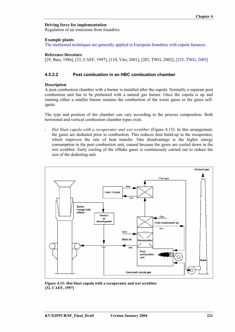
Chapter 4
KV/EIPPCB/SF_Final_Draft Version January 2004 221
Driving force for implementationRegulation of air emissions from foundries.
Example plantsThe mentioned techniques are generally applied in European foundries with cupola furnaces.
Reference literature[29, Batz, 1986], [32, CAEF, 1997], [110, Vito, 2001], [202, TWG, 2002], [225, TWG, 2003]
4.5.2.2 Post combustion in an HBC combustion chamber
DescriptionA post combustion chamber with a burner is installed after the cupola. Normally a separate postcombustion unit has to be preheated with a natural gas burner. Once the cupola is up andrunning either a smaller burner sustains the combustion of the waste gases or the gases self-ignite.
The type and position of the chamber can vary according to the process composition. Bothhorizontal and vertical combustion chamber types exist.
- Hot blast cupola with a recuperator and wet scrubber (Figure 4.13): In this arrangement,the gases are dedusted prior to combustion. This reduces dust build-up in the recuperator,which improves the rate of heat transfer. One disadvantage is the higher energyconsumption in the post combustion unit, caused because the gases are cooled down in thewet scrubber. Early cooling of the offtake gases is continuously carried out to reduce thesize of the dedusting unit.
Figure 4.13: Hot blast cupola with a recuperator and wet scrubber[32, CAEF, 1997]

Chapter 4
222 Version January 2004 KV/EIPPCB/SF_Final_Draft
- Hot blast cupola with a recuperator and bag filter (Figure 4.14): The hot, dust laden, topgases are fed directly into the post combustion unit. Close process control is necessary toprevent sintering of the dust particles to the walls of the recuperator, which need to becleaned regularly. The gases need further cooling before entering the bag filter since theyleave the recuperator at temperatures of 500 to 600 ºC.
Figure 4.14: Hot blast cupola with a recuperator and bag filter[32, CAEF, 1997]
Achieved environmental benefitsPost combustion limits the emissions of CO and eliminates the majority of organic compounds.If not combusted, these would be captured in the dust or emitted through the chimney.Furthermore, post combustion reduces the risk of fire in the filter.
Cross-media effectsDry dedusting techniques produce dust for disposal (4 – 12 kg/t liquid iron). The dust may bere-circulated into the cupola. This is discussed in Section 4.9.4.2. Wet systems produce a sludgefraction.
Operational dataOperational data for hot blast cupolas are given in Table 4.37. Data for two example plants aregiven:
1. Foundry G is a 3 shifts/days and 5 days/week operated foundry with a melting capacityof 50 t/h. The off-gas is collected below the charge-hole and combusted in arecuperator. The waste gas is then separated: one part goes to hot blast production (T =600 ºC), another part goes to a steam boiler. The steam is fed into a turbine, whichpowers a generator or compressor. The residual heat is used for preheating thecombustion air of the recuperator. Waste gas is then cleaned in a bag filter. A conceptdrawing and further discussion of the installation is given in Section 4.7.3. Dust isrecycled into the cupola, after mixing with petcokes. This is discussed in Section4.9.4.2.

Chapter 4
KV/EIPPCB/SF_Final_Draft Version January 2004 223
2. Foundry H is a 3 shifts/day and 5 days/week operated foundry with a melting capacityof 70 t/h. The off-gas is collected below the charge-hole and washed in a disintegrator,before post combustion in a recuperator. Heat is used for blast air preheating and goesto a further heat recovery, before leaving through the stack at a temperature of 220 ºC.Further discussion of the heat recovery installation is given in Section 4.7.3. Wastewater is re-circulated after settling. The circulating water volume is 440 m³/h. Thesludge from the settling tank is dried in a filter press to a 50 % DS content, beforedisposal. Some 80 m³/day of waste water are disposed to the municipal waste watertreatment.
Units Plant G Plant HMelting capacity tonne/h 50 50Waste gas flow Nm³/h 75000 55000Hot blast temperature o C 600 570Exhaust gas temperature o C 127 220Year of construction of theflue-gas treatment
1989 1983
Date of the measurements 10/1990 Control measurement09/1993
Emissions- Dust� Raw gas� Clean gas: average1
maximum- Gaseous2
� SO 2� NO x� Ctotal
� CO� O 2
mg/Nm3
%
1300 – 43001.11.8
3344<532
12.2
8000 – 200006.17.3
15.652.5
28.6 (FID)<1006.4
Heavy metal emission- Cr- Crtotal- Pb- Zn- Ni
mg/Nm3 Clean gas3
<0.001<0.001<0.001<0.011
n.d
Clean gas<0.0022
n.d0.110.36
<0.004PCDD/F-emissions1
- Clean gas4
- Emission factorng TEQ/Nm3
µg TEQ/tonneFe
0.0480.089
0.0030.004
Filter dust/sludge- solitary quantity- PCDD/F-content
kg/tonne Feµg TEQ/kg
Dust recycling4.5
0.176
Filter cakes to disposal5.51.4
Waste heat utilisation Hot blast air, steam forelectricity production upto 3 MW electric
Hot blast air, thermal oil forthe conversion of the wasteheat for heating and dryingpurposes up to 21 MW
Investment cost DEM ‘000 26400 22700 in 1980/81Operational cost DEM/tonne
good castingSee data in the text for
foundry GSee data in the text for
foundry H1 Dust average is calculated on basis of 5 - 6 half-hour measurement data and 2x2 hour values for PCDD/F2 The concentrations of sulphur dioxide, nitrogen oxide, total carbon, carbon monoxide and carbon dioxide are
calculated averages from continuous measurements over several hours during sampling for dust or PCDD/F3 At the time of measurement, the dust recycling was not operational4 Sampling time of 2 hours
n.d: no datanote: Raw gas sampling was performed before the bag filter in G and before the disintegrator for H; clean gassampling was performed after the bag filter for G and after the recuperator for H
Table 4.37: Operational data of hot blast cupola furnaces using a bag filter and a disintegrator fordust capture[17, Strauß, 1983], [27, Kran, et al., 1995], [202, TWG, 2002]

Chapter 4
224 Version January 2004 KV/EIPPCB/SF_Final_Draft
Burning the fumes in the post combustion chamber does not consume much energy, providingthere is sufficient carbon monoxide in the fumes, which is generally the case. But the wholesystem for treating the fumes (combustion chamber + heat-exchanger + filter or wet scrubber +fans) also needs electrical energy and regular maintenance. Table 4.38 gives some examples ofenergy consumption for hot blast cupolas.
Hourly rateof the cupola
Type of dedusting Gas consumption forthe combustion
chamber(kWh/t charged)
Electricity consumptionfor the fume treatment
system(kWh/t charged)
12 Filter 59 4612 Filter 124 7226 Filter 42 n.d17 Electro filter (wet) 16 38
Table 4.38: Energy consumption of hot blast cupolas
ApplicabilityDuring the design stage, considerable care has to be taken to minimise the total flow of thegases to be treated. The combustion air intake has to be kept to a strict minimum. This is thereason why a separate combustion unit is always installed in conjunction with a below charge-hole offtake.For economic reasons (see below) the post combustion chamber is only used on hot blastcupolas.
EconomicsThe high energy consumption of the post combustion is only economically reasonable if thereleased heat of the waste gases can be re-used, as it is in the recuperative hot blast cupola.However, switching from a cold blast to a hot blast cupola for the sole reason of gas combustionmight encounter economical limitations in certain situations. Hot blast cupolas, preferably in along campaign configuration, involve higher investment costs and are only used with productionrates of 10 tonne Fe/h or more. In smaller foundries this production method might not be theright choice.
Table 4.37 gives economic data for the example plants. For foundry G, the investment costs fora hot blast cupola with bag filter and extensive heat recovery are given. The operational costsfor 1994 (after refurbishment of the melting shop) were 25 % lower than those for 1985, i.e.with the old melting furnace. For foundry H, investment costs for 1980 - 1981 are given. Afterrefurbishment, the operational costs went down by 2 %/tonne of liquid iron.
Driving force for implementationEmission limit values and continuous monitoring of CO and emission limit values for organiccompounds.
Example plantsThe technique finds general application in HBCs around Europe.
Reference literature[17, Strauß, 1983], [27, Kran, et al., 1995], [32, CAEF, 1997], [157, Godinot, et al., 1999], [202,TWG, 2002]
4.5.2.3 Post combustion in the cupola shaft
DescriptionThe gases are combusted by an injection of air into the upper part of the charge or at a positionabove the charge top level. The airflow is adjusted so that the off-gases ignite spontaneously,due to their CO content and temperature. The injection nozzles can be placed on one or twolevels. The partitioning of the airflow over the various levels, the choice of diameter and the

Chapter 4
KV/EIPPCB/SF_Final_Draft Version January 2004 225
position of the nozzles is based on experience. The goal of the optimisation is to burn the COwithout ignition of the coke. The draught will also suck in air from the charge door. This airexcess allows a more complete burn-out of the CO.
A supporting burner may be provided to maintain the flame. When using very low coke charges(i.e. <6 – 8 %) the precautionary measure is reasonable.
Post combustion of the off-gas must be combined with a gas cooling, if a bag filter is used. Forhot blast cupolas, the cooling is combined with a blast air preheating. In cold blast operation, arapid cooling may be applied using water injection in the furnace shaft. Alternatively, an (off-gas – air) heat-exchanger may be used. This is illustrated in Figure 4.15.
Figure 4.15: Principle of post combustion and off-gas cooling in cold blast cupolas[157, Godinot, et al., 1999]
Installing post combustion on cold blast cupolas can be combined with a full retrofit to hot blastoperation. In general, this choice is based on operational considerations. The characteristics ofhot blast and long campaign furnaces are discussed in Section 2.4.1.
Achieved environmental benefitsPost combustion limits the emissions of CO and eliminates the majority of organic compounds.If not combusted, these would be captured in the dust or emitted through the chimney.Furthermore, post combustion reduces the risk of fire in the filter.
This technique is known to avoid explosion risks under certain circumstances. The positiveenvironmental effect is limited to those cases when the off-gas is burning autothermally most ofthe time. Otherwise, the energy consumption will counterbalance the CO reduction.
Cross-media effectsIf the cupola off-gas does not ignite spontaneously, the installation of ignition or supportburners is necessary. These incur a significant power use and increase the overall flue-gasvolume.
Operational dataTwo configurations of (in-shaft post combustion and) cooling on cold blast cupolas werestudied on an industrial scale and compared by CTIF; cupola I was equipped with a waterinjection in the cupola shaft, a cyclone and a bag filter, cupola J was equipped with a gas-airheat-exchanger, a cyclone and a bag filter. Operational data are given in Table 4.39. Results ofthe measurement campaigns and reference to the applicable legislation are given in Table 4.40.

Chapter 4
226 Version January 2004 KV/EIPPCB/SF_Final_Draft
Parameter Units Foundry I Foundry JMelting capacity tonne/h 10.3 9.2Primary + secondary airflow Nm³/h 7389 6484Post combustion airflow Nm³/h 2372 1549Water flow l/h 2678Flue-gas flow (chimney) Nm³/h 26780 39179Residence time combustion to bag filter s 10.5 12.3Residence time cooling stage s <1.7 6.01Overall CO combustion efficiency % 66 96.5
Table 4.39: Operational data of two example configurations using post combustion with watercooling (I), and air cooling (J)[157, Godinot, et al., 1999]
Foundry I Foundry J Arrêté du 02/02/98Compound analysis flux analysis flux limit value limit for
consideration*Dust 1.7 – 2.8 mg/Nm³
3 – 5 g/t0.04 – 0.07 kg/h 1 mg/Nm³
34 g/h100 mg/Nm³
200 g/t<1 kg/h
melt = 8 tonne/hCO 450 Nm³/h 560 kg/h 35 Nm³/h 44 kg/h 50 kg/hHCl 22 mg/Nm³ 0.4 kg/h 9.2 mg/Nm³ 0.35 kg/h 50 mg/Nm³ 1 kg/hHF 13 mg/Nm³ 0.24 kg/h 4.8 mg/Nm³ 0.18 kg/h 5 mg/Nm³ 0.5 kg/hHCN <0.007 mg/Nm³ 0.13 g/h <0.01 mg/Nm³ 0.38 kg/h 5 mg/Nm³ 50 g/hNH3 0.61 mg/Nm³ 12 g/h 0.10 mg/Nm³ 3.8 g/h 50 mg/Nm³ 100 g/hNOx 9 mg/Nm³ 0.17 kg/h 15 mg/Nm³ 0.57 kg/h 500 mg/Nm³ 25 kg/hVOC non-methane
13 mg/Nm³ 0.25 kg/h 6 mg/Nm³ 0.23 kg/h 110 mg/Nm³ 2 kg/h
*: If the flux is below the limit of consideration, the measured value may exceed the limit value
Table 4.40: Analytical results and applicable (French) legislation, for post combustion in a coldblast cupola with water cooling (I), and the air cooling (J) of flue-gases[157, Godinot, et al., 1999]
The water spray cooling achieves a CO-destruction efficiency of 66 % and allows compliancewith the applicable legislation. Flue-gas cooling over a heat-exchanger provides betterefficiency (98 %). For discussion on cooling performance, see also 4.5.2.1.
ApplicabilityTo change the offtake system of an existing cupola from above to below the charge-hole systemis in most cases impossible. Post combustion of the waste gases in the furnace shaft therefore isa more viable solution for cupolas with an above charge-hole offtake.
For economic reasons, the application of post combustion has mainly been related to hot blastcupolas. However, recently, a post combustion system for cold blast furnaces, without thecomplexity of a hot blast installation, has also been developed. This system is currently inoperation in France. ‘In-shaft’ post combustion therefore applies to both hot blast and cold blastcupola operation.
In the Czech Republic, the whole range of cold blast cupola installations was studied forapplicability of in-shaft post combustion. The combustion was not spontaneous in any of theset-ups over the whole melting period. In each case, it was necessary to install ignition burnersof significant power. The cupola emission volume also increased.
EconomicsThe high energy consumption of the post combustion needs to be evaluated against its benefits.In hot blast operation, the released heat of the waste gases can be re-used, which makes theinvestment more viable.
The high energy consumption of the post combustion is only economically reasonable if thereleased heat of the waste gases can be re-used, as it is in the recuperative hot blast cupola.However, switching from a cold blast to a hot blast cupola for the sole reason of gas combustion

Chapter 4
KV/EIPPCB/SF_Final_Draft Version January 2004 227
is not possible. Hot blast cupolas, preferably in a long campaign configuration, involve higherinvestment costs and are only used with production rates of 10 tonne Fe/h or more. In smallerfoundries, this production method might not be the right choice.
The investment cost for a twin cold blast cupola of 850 mm internal diameter, which produces4.5 tonnes an hour, 10 hours a day, 5 days a week is in the order of EUR 300000.
Driving force for implementationEmission limit values and continuous monitoring of CO and emission limit values for organiccompounds.
Example plantsThe technique is reported in 2 example foundries in France.
Reference literaturehot blast: [150, ETSU, 1998], [202, TWG, 2002]cold blast: [157, Godinot, et al., 1999], [202, TWG, 2002]
4.5.3 EAF
4.5.3.1 Off-gas collection
DescriptionParticulate matter from an EAF is very fine and difficult to capture. The capture of smoke anddust is the most difficult problem to solve when installing a dust arrestment system on anelectric arc furnace. There are several methods that offer different advantages anddisadvantages. Figure 4.16 depicts the principle of roof mounted hoods, side-draught hoods andfourth-hole evacuation.
Figure 4.16: Principle drawings of (a) a roof mounted hood, (b) a side-draught hood, and (c) directevacuation through a fourth-hole[173, Huelsen, 1985]
- Roof mounted hoods: A hood is fixed on the furnace roof and collects fumes through a gapbetween the furnace shell and the roof. In addition, fumes arising from the working doorand the tap-hole are also captured. Roof mounted hoods are heavy and subject to distortionfrom heat. If fitted to an existing EAF, problems may arise due to increased structural loadof the roof lifting and rotating mechanism. Typical extraction rates for this system are 7500to 15000 Nm3/tonne
- Side-draught hoods: A hood is mounted on the furnace roof and collects the fumes emittedthrough the electrode ports. Vanes direct the airflow towards the hood. Additional hoodsabove the working door and the tapping-hole are used to capture emissions at theselocations. Higher extraction rates are necessary here, compared to roof mounted hoods, ashigh air draught velocities are needed to capture the fumes. Some leakage of pollutants tothe plant atmosphere can be expected, unless a tight seal is maintained. It has been reportedthat side-draught hoods increase electrode consumption

Chapter 4
228 Version January 2004 KV/EIPPCB/SF_Final_Draft
- Canopy hoods: A large exhaust hood is placed over the complete furnace, and above thecharging system. This creates a large gap between the furnace and the extraction system,making it difficult to control the rising smoke and dust, even when using high extractionrates. Cross-draughts can seriously distort the collection efficiency. These disadvantagesmake the use of these collection systems unattractive
- Direct furnace or “fourth-hole” evacuation: The fumes are collected through a water-cooled or refractory-lined duct connected to a fourth-hole in the furnace roof. Ambient air isaspirated through a joint in the ductwork, thus providing oxygen to burn the CO gas in theundiluted and hot offtake gas. This prevents explosions in the dust collecting system. Thedimensions of the combustion chamber are very critical in order to guarantee sufficientcombustion at all stages of the melting cycle. The burnt gas (900 ºC) is cooled downstreamby dilution with ambient air, water injection, heat-exchangers (water jackets) or by the useof long ducts. This cooling process is needed to protect the dust filter equipment. The use ofa pressure control system in the furnace allows a relatively small extraction rate at thefurnace at 2000 to 4000 Nm3/tonne. Electrode consumption is generally higher due to theeffect of oxidation
- Partial furnace enclosure: Mobile or fixed enclosures are mounted around the furnace andtapping area. The former are retracted in order to accommodate charging and tapping, whilethe latter are equipped with a mobile roof and side-walls for the same purpose. Exhaustgases are collected through a main exhaust duct at the top of the enclosure, assisted by fansinside the duct to guide the fumes to the exhaust. With these types of system collection,efficiencies of up to 98 % are possible
- Total furnace enclosure: This system consists of a large fixed evacuated room completelysurrounding the melting furnace and ladle pit. The enclosure is equipped with a movableroof and/or with side panels to accommodate both charging and tapping operations. Thesemay be equipped with air curtains to reduce gas losses. Disadvantages of the technique arethe high temperatures and noise levels inside the enclosure. However, the advantagesinclude low outside noise levels and low energy consumption. The energy consumption isestimated to be 30 to 50 % less than that required for a canopy hood.
Achieved environmental benefitsFlue-gas capture allows the controlled evacuation and treatment of the flue-gas stream, andresults in a minimisation of both fugitive and guided emissions.
Cross-media effectsCapturing the exhaust increases the energy consumption. As it allows the cleaning of theexhaust gas, it will also generate dust for disposal or re-use.
Operational dataTable 4.41 provides typical exhaust flowrates and removal efficiencies for various capturesystems.
Exhaust flowratefor given furnace capacity
Particulate removalefficiency (%)
3.9 t/h 9.1 t/h 22.7 t/h Range Typical max.Side-draught hood 12.9 19.8 50.00 90 – 100 99Roof hood 7.7 11.9 30.00 95 – 100 99Direct evacuation 3.2 5.0 12.5 90 – 100 99Total enclosure 35 – 42
Table 4.41: Typical exhaust flowrates (in m³/s) and particulate removal efficiency of EAF exhaustcapture systems[173, Huelsen, 1985]
In a Polish foundry, the installation of a total enclosure over two EAFs with a capacity of8.5 tonnes each, resulted in a reduction of the noise level from melting from 91 dBA to less than85 dBA.

Chapter 4
KV/EIPPCB/SF_Final_Draft Version January 2004 229
ApplicabilityThe above-mentioned techniques are applicable to all new and existing EAF furnaces, with thefollowing limitations:- when installing a roof mounted hood on an existing furnace, problems may arise due to the
increased structural load from the roof lifting and rotating mechanism- direct furnace evacuation using a fourth-hole is limited to big electric arc furnaces, as the
roof must be big enough to accommodate a fourth-hole without any structural weakening.The technique is not applicable for iron melting, because the in-flow of fresh air generatesan excessive oxidation of carbon.
EconomicsThe construction and assembly of a doghouse over two EAFs with a capacity of 8.5 tonneseach, involved an investment of EUR 275000 (1996 prices), excluding costs for furtherrefurbishment of the ducting and filtration system.
Driving force for implementationWorkers health-related prevention measures. It allows application of a gas cleaning techniqueby guiding the exhaust gas flow.
Example plantsdoghouse: Metalodlew Foundry, Krakow (PL)off-gas collection: Metso Lokomo Steels and Sulzer Pumps Karhula Foundry (FIN)
Reference literature[29, Batz, 1986], [32, CAEF, 1997], [173, Huelsen, 1985], [199, Metalodlew s.a., 2002]
4.5.3.2 Exhaust gas cleaning
DescriptionGas cleaning systems for EAF flue-gas need to be highly efficient since the particle size issmall. Fabric filters are widely used to dedust the exhaust gases. Venturi scrubbers ordisintegrators are applied less due to their higher energy consumption, the necessity for watertreatment prior to discharge, and due to the need to dispose or recycle wet filter sludge. Fabricfilters are widely used in favour of electrostatic filters, due to the wide fluctuations in gastemperature and the particulate concentration of the exhaust gases.
If a fabric filter is used, several precautions need to be taken in order to protect the filtermedium as discussed in Section 4.5.1.3. These include:- using a high temperature cyclone or multicyclone- using gas cooling equipment. Here the exhaust gases are cooled by dilution with ambient
air, water injection (quenching), heat-exchangers or by the use of long ducts. Waterinjection, in particular, has an additional advantage, in that the quick cooling down of theexhaust gases prevents the recombination of any partially burned organic substances,thereby leading to a cleaner emission. The cooling system needs an effective control systemto prevent gases which are too hot from entering the fabric filters.
Achieved environmental benefitsReduction of particulate emissions from EAF.
Cross-media effectsThe application of wet dedusting techniques causes a higher energy consumption, the necessityfor water treatment prior to discharge, and the need to dispose or recycle wet filter sludge.
Operational dataOperational data are given in Section 3.2.3.4. Current bag filters have air to cloth ratios between2:1 and 3:1. The air to cloth ratio is the ratio of volumetric airflow through the filter to the

Chapter 4
230 Version January 2004 KV/EIPPCB/SF_Final_Draft
media area and is expressed in (m³/s)/m², which yields the same result as the air speed throughthe filter media.
ApplicabilityThese techniques can be applied to all new and existing installations.
EconomicsThe costs for installing a new dust capture and filtration unit in an existing Polish EAF foundryusing two 8.5 t/h melting furnaces are summarised in Table 4.42. Dust emissions have beenreduced from 10 – 13 kg/h and 145 – 150 mg/Nm³ to 0.2 – 0.25 kg/h and 2.8 – 2.9 mg/Nm³.There has also been a major reduction of diffuse emissions from the melting shop.
Investment costs EUR*Foundation and remodelling of old collector 115000Construction and assembly of doghouse housings over 2 furnaces 275000Purchase and assembly of filtration unit and electrical devices 560000Research, implementation and supervision 80000Operational costs EUR/yearDepreciation cost 100000Electric power 88000Repairs and service 1500* Prices converted from zlotys 1999
Table 4.42: Cost data for EAF flue-gas capture and cleaning equipment[199, Metalodlew s.a., 2002]
Driving force for implementationRegulation limiting the dust emissions from the melting of metals.
Example plantsdoghouse with bag filter unit: Metalodlew Foundry, Krakow (PL)Metso Lokomo Steels and Sulzer Pumps Karhula Foundry (FIN)
Reference literature[173, Huelsen, 1985], [32, CAEF, 1997], [29, Batz, 1986], [199, Metalodlew s.a., 2002]
4.5.4 Induction furnace
4.5.4.1 Off-gas collection
DescriptionThe capture of smoke and dust is the most difficult problem to solve when installing an off-gascollection system on a coreless induction furnace, since there is no exhaust shaft. Severalmethods have been developed in the past decade, each with advantages and disadvantages.- General ventilation of the workplace: A combination of wall mounted louvres and roof
mounted ventilators situated over the furnace platform are used to increase the naturalconvection of smoke and fumes and to direct them outside. Even with baffles suspendedfrom the roof and using high extraction rates the efficiency is often poor and easilydisturbed by draughts.
- Canopy hood extraction: Since lower placed hoods will interfere with crane chargingsystems, larger hoods have to be installed above the charger. This creates a large gapbetween the furnace and the extraction system, making it difficult to control the risingsmoke and dust, even when using high extraction rates. Cross-draughts can seriously distortthe collection efficiency of the system. These disadvantages make the use of thesecollection systems unattractive.

Chapter 4
KV/EIPPCB/SF_Final_Draft Version January 2004 231
- Swing aside hoods: These hoods are more efficient when used in conjunction with vibratingfeeders. Cut-outs in the hood can facilitate charging. During tapping, the hood is swungover the ladle, allowing efficient fume extraction.
- Side-draught hoods: Placing the extraction hood beside the furnace offers the advantage ofgood furnace accessibility and no interference with the charging systems. Due to the highbuoyancy of the exhaust gases, large extraction rates are achieved, therefore giving goodefficiency, especially when the hood is placed outside the furnace platform. In this caseextraction control is poor during tapping. Attachment to the furnace platform overcomesthis problem but may interfere with charging operations. The efficiency can be improved byinstalling airjets at the opposite side of the hood to blow the dust and fumes into the hood.Unfortunately, this facility does not work if there are any interferences in the airstream,which is the case during charging.
- Lip extraction: A suction ring is placed on top of the furnace and arranged so that it moveswith the furnace during deslagging or tapping operations. This system does not interferewith the charging operations. With the lid closed, lip extraction offers very good control,since it is as near to the emission source as possible and involves the lowest extraction rates.The fumes do not pass through the breathing zone of the furnace operators. However, theextraction control decreases significantly when the furnace lid is opened, for instance duringcharging.The design of this extraction equipment has been subjected to many studies. Suppliers offersolutions to overcome some of the disadvantages.
- Cover extraction: The gas is exhausted through the furnace cover. This method is veryeffective. It is used by the majority of furnace producers. Exhaustion is managed accordingto furnace regime: melting, charging, pouring.
Attention has to be paid to the material used for hoods and ducts since the gases may be at hightemperatures when the intake of the collection system is positioned close to the furnace. Theheating required by radiation or convection from the molten metal bath needs to be taken intoaccount in the design stage. Proper maintenance in combination with heat-sensors reduces therisk of fire.
Again scrap cleanliness plays an important role. When the scrap contains organic matter,collected gas temperatures may rise due to the combustion of the material, thus requiring the useof heat resistant steel or even refractory linings. Oily deposits, formed by condensation of oilvapour in the ductwork, accumulate dust and can present a fire hazard if not removed regularly.When using clean scrap, a mild steel construction is adequate and does not need accessibility forcleaning.
Achieved environmental benefitsFlue-gas capture allows controlled evacuation and treatment of the flue-gas stream, and resultsin a minimisation of both fugitive and guided emissions.
Cross-media effectsApplying exhaust capture increases the energy consumption. In addition, as it allows thecleaning of the exhaust gas, it will also generate dust for disposal or re-use.
Operational dataThrough the use of specific capture systems, such as side-draught hoods, movable extractionhoods and partial housing of the furnace, a capture efficiency of more than 95 % is possible.
Operational experience in a German cast iron foundry showed that the furnace lid is open onaverage during 25 % of the working time of the furnace. During the opening periods, dust-generating process steps such as the feeding of additives, deslagging and pouring are performed.The lip extraction system installed on the furnace lid, does not allow extraction of the generatedfumes. Installation of a telescopic canopy hood allowed an efficient exhaust capture during theopening of the furnace lid.

Chapter 4
232 Version January 2004 KV/EIPPCB/SF_Final_Draft
ApplicabilityThe installation of exhaust capture equipment is applicable to all new and existing inductionfurnace installations, both in ferrous and non-ferrous foundries.
Driving force for implementationRegulations concerning emissions to air.
Example plantsThese techniques are commonly used on induction furnaces in Europe. A specific example isWalter Hundhausen GmbH & co KG (D)
Reference literature[29, Batz, 1986], [18, Rademacher, 1993], [32, CAEF, 1997]
4.5.4.2 Exhaust gas cleaning
DescriptionGas cleaning systems for induction furnace flue-gas need to be highly efficient as the particlesizes need to trap are small. Fabric filters are widely used to dedust the exhaust gases. Fabricfilters are used in favour of electrostatic filters, as they are more suited to the wide fluctuationsin gas temperature and particulate concentration of the exhaust gases.
When using fabric filters care has to be taken with respect to the presence of oil in the scrap, asoily vapour could condense on the filter cloth, where it could block the pores and make theremoval of adhering dust impossible. There is also a possible fire hazard. The rapid increase inthe pressure loss of the system when pores get blocked quickly reduces the extraction rate of thesystem. Therefore, in order to prevent workplace pollution the filter media have to be changedor regenerated (cleaned) much quicker than when using clean scrap. The use of coated fabrics oran injection of lime in the ductwork may be a solution to this problem. Furthermore, if the oilvapour is likely to burn in the ductwork, the process must allow enough time for combustion tobe completed before the vapour enters the filter housing. The gas temperature may not exceedthe design temperature of the fabric, in which case cooling of the gases may therefore beneeded.
The wet scrubbers used generally need to be of the high energy type (venturi), becausecarbonaceous and metallurgical smoke consists of very small particles. These requireconsiderable fan power to create sufficient turbulence in the scrubber to collect the particles.Exhaust flowrates are therefore kept to a minimum by using exhaust capture systems with theleast entrainment of ambient air. Under normal conditions, corrosion is not a problem. If boringscontaining cutting fluids are charged into the furnace, it should be noted that some of thesefluids might contain sulphur, which could lead to the formation of SO2. This could causeproblems in the equipment, as the absorption of SO2 in the scrubber leads to an acidification ofthe water and eventually to corrosion of the equipment if water treatment is not applied.
Some aluminium foundries melt material recovered from the electrolysis of aluminium. In thisinstance, inorganic pollutants such as hydrogen fluoride may be formed. These can be cleanedfrom the flue-gas using a chemisorption step, which can be added onto the dust abatementsystem. In this treatment calcium hydrate or aluminium oxide can be used as the adsorbant.
Achieved environmental benefitsTo reduce particulate and acidifying emissions from induction melting furnaces.
Cross-media effectsExhaust gas cleaning increases the energy consumption. The dedusting of the exhaust gas,generates dust for disposal or re-use. The application of wet dedusting techniques lead to a

Chapter 4
KV/EIPPCB/SF_Final_Draft Version January 2004 233
higher energy consumption, the necessity of water treatment prior to discharge, and the need todispose of or recycle wet filter sludge.
Operational dataCleaning of the captured gases is generally performed using filters. Daily average dust emissionvalues stay well below 10 mg/Nm³. Operational data are given in Section 3.2.4.1.
Table 4.43 gives the operational data for a German cast iron foundry in which a centralised flue-gas capture system is installed, with dedusting carried out using a bag filter. The system collectsexhaust gas from the various parts of the foundry, including: the four induction furnaces (eachwith lip extraction and canopy hood), the scrap storage and preheating, the metal treatment, thesand regeneration, and the casting areas. Data are given for the raw melting of the furnace off-gas, the raw combined gas flow and the cleaned gas flow.
Compound Melting off-gas Combined exhaust gas Cleaned gas*Dust 89.3 237 <1NOx 1.6 8.3 7.9CO 2.2 4.2 3.8SO2 3.5 3.9 3.7Total C 21.8 34.7 34.9PCDD/-F 0.036 x 10⁻⁶ 0.0027 x 10⁻⁶
* NOx, CO, SO2 and total C are not captured in the bag filter. The difference between raw andcleaned gases are due to the slightly changed gas mix after the ID fanMelting capacity 14 tonne/h, total flue-gas flow 240000 m³/hAll data in mg/Nm³
Table 4.43: Emission data for a cast iron foundry, using induction melting and a centralisedexhaust system with a bag filter[18, Rademacher, 1993]
ApplicabilityThis technique is applicable to all new and existing induction furnace installations, both inferrous and non-ferrous foundries.
EconomicsThe cost and consumption data for a bag filter installation on a melting unit of crucibleinduction furnaces, melting 15 t/h, able to treat 120000 Nm3/h are given in Table 4.44.
Dust emission level(mg/Nm³)
Investment cost(EUR)
Power consumption(kW)
<5 350000 250<20 200000 150
Table 4.44: Investment cost and power consumption for a bag filter unit on induction furnaces,with varying final dust emission levelsdata for Portugal 2003[225, TWG, 2003]
Driving force for implementationRegulation limiting the dust emissions from the melting of metals.
Example plantsFlue-gas cleaning is applied in most ferrous foundries using an induction furnace and in alimited number of non-ferrous foundries.
Reference literature[18, Rademacher, 1993], [32, CAEF, 1997], [29, Batz, 1986]

Chapter 4
234 Version January 2004 KV/EIPPCB/SF_Final_Draft
4.5.5 Rotary furnace
4.5.5.1 Off-gas collection and waste gas cleaning
DescriptionIn most cases, dedusting equipment is needed to meet the applicable regulations. Generally, bagfilters are installed for this purpose, but it is also technically possible to use wet dedustingtechniques.In order to lower the temperature of the exhaust gases, they are diluted with ambient air. This isachieved by the intake of air through a gap between the furnace exhaust and the elbow shapedexhaust pipe. This gap is always present as it allows the furnace body to be able to rotate andtilt. Often the exhaust pipe is retractable. In general, dilution for emission reduction isunacceptable. If dilution is used (and is necessary) for cooling, the end-of-pipe technologyshould have the right dimension for the larger gas flow. Sometimes the diluted waste gases arethen fed through an air-gas heat-exchanger for further cooling. This way the gas temperature isreduced from the initial 1500 ºC to 200 ºC, or lower. At this temperature, the gases can beintroduced into a bag filter for dedusting.
The application of an afterburner allows the reduction of organic carbon emissions andcombustible particles. This technique may also be effective in reducing the risk of dioxinformation upon cooling of the gases. The afterburner is installed after the furnace and before theheat-exchanger. One of the following afterburner types may be used:- thermal incinerator: combustion in an open flame- catalytic incinerator: combustion at lower temperatures through the use of a catalyst,
resulting in a higher efficiency and lower NOx emissions- recuperative incinerator: combustion with a heat recovery for preheating the combustion air,
resulting in a higher thermal efficiency and lower fuel consumption- catalytic recuperative incinerator: a combination of the previous two types.
Achieved environmental benefitsReduction of particulate emissions from rotary furnaces.
Cross-media effectsExhaust gas cleaning increases the energy consumption. The dedusting of the exhaust gasgenerates a dust for disposal or re-use.
Operational dataOperational emission data are given in Section 3.2.5.3.
An afterburner can be expected to achieve between 80 % and 98 % efficiency for burning thecombustible particulates emitted from the rotary furnace. Hot gases from the afterburner can beducted through a recuperator and can assist in preheating the combustion air to the main furnaceburner. Recuperators offer an energy saving of up to 15 %.
ApplicabilityThis technique is applicable to all new and existing rotary furnace installations, both in ferrousand non-ferrous foundries.
Driving force for implementationRegulations limiting the dust emissions from the melting of metals.
Example plantsThis technique is commonly applied in foundries using a rotary furnace.
Reference literature[23, Brettschneider and Vennebusch, 1992], [32, CAEF, 1997], [163, UK Environment Agency,2002], [202, TWG, 2002]

Chapter 4
KV/EIPPCB/SF_Final_Draft Version January 2004 235
4.5.6 Crucible, hearth type and radiant roof furnaces
4.5.6.1 Prevention of visible and fugitive emissions during melting andmetal treatment
DescriptionUnder normal operating conditions, melting processes using pure metal melts do not emitvisible smoke. However, during charging of the furnace it is possible that a visible smoke maybe produced. This can be either due to the burning of contaminants in the charge, such as oil orpaint, or due to the burner flame being extinguished and unburned fuel being emitted, as may bethe case with solid or liquid fuels. In these circumstances, an afterburner may be installed.
Hoods may also be installed to capture visible smoke and fugitive emissions. The melting ofclean scrap prevents or minimises these types of emissions.
Achieved environmental benefitsA reduction of the emission to air of the products from incomplete combustion.
Cross-media effectsSmoke capture will involve a usage of electrical energy.
ApplicabilityThis technique applies to new and existing crucible and hearth type furnaces.
For implementation, any constraints due to the current furnace design and operation need to beconsidered. These include physical constraints, for example due to crane tracks, the existingstructural elements of the building, or due to the furnace itself. To be effective the extractionneed to be fitted in such a way that it moves with the furnace body when it is tilted to pour, astapping-out is one of the peak emission operations. This is not always easy to achieve withexisting furnace bodies. There can also be physical problems related to the location ofassociated ducting. In some cases, major modifications to the furnace platform and surroundingarea may be necessary to enable the ducting to be installed.
EconomicsA cost estimate for an extreme (worst case) scenario, i.e. needing to capture all the dusts fromcharging and tapping, was made by CTI. Table 4.45 summarises this financial data for an‘average foundry’ with the costs depreciated over a presumed 10 year lifespan of the extractionand abatement equipment. This estimation however, can broadly vary, depending on thefoundry layout and the techniques used.
CostsEUR
CostsEUR/tonne of iron melted
Extractionrate
m³/minute
Productionrate
tonnes/hr Capital Civil
PowerkW
Running Financial Total
142 0.5 117573 15676 40 15.24 18.81 34.05(1150 tonnes
per year)Note:- Civil costs are taken as 12 % of capital costs- Running costs are based on maintenance and waste disposal costs and are equivalent to 10 % of the capital
costs and power at EUR 0.06/kWh- Financial costs are based on the plant being amortised over ten years with interest charges of 10 %
Table 4.45: A cost estimate for installation of an abatement system for visible fumes duringcharging and tapping[161, UK Environment Agency, 2002]
In this example, under the pre-conditions used, the costs for abatement of these visibleemissions would be about EUR 34.05 per tonne of metal melted.

Chapter 4
236 Version January 2004 KV/EIPPCB/SF_Final_Draft
Driving force for implementationRegulations limiting the occurrence of visible emissions.
Example plantsThis technique is commonly applied in foundries around Europe.
Reference literature[161, UK Environment Agency, 2002]
4.5.7 Metal treatment
4.5.7.1 AOD Converter: exhaust gas capture and treatment
DescriptionPollution control equipment need to be designed to be able to handle the peak effluentcondition, even though the peak may only persist for a relatively short period.
Fume control hoods for AOD vessels come in a great variety of shapes and sizes. Thealternative to the direct extraction hood is the roof canopy. Roof canopies are in use in severalAOD plants and efficiently capture both AOD process fumes and smoke from other operationssuch as charging and tapping. These roof canopies may be used in conjunction with acceleratorstacks over the AOD mouth. The accelerator stack performs several useful functions, includingforming a more coherent plume out of the AOD, reducing the size of canopy required, andshielding the surrounding equipment and personnel from the sometimes intense radiation of theAOD flame. The main advantage of the roof canopy is the capture of both process and fugitiveeffluents in the same hood.
Achieved environmental benefitsFlue-gas capture allows controlled evacuation and treatment of the flue-gas stream, and resultsin a minimisation of both fugitive and guided emissions.
Cross-media effectsExhaust gas cleaning increases the energy consumption. The dedusting of the exhaust gasgenerates dust for disposal or re-use.
ApplicabilityThis technique is applicable to all new and existing AOD installations.
Driving force for implementationRegulations limiting the dust emissions from the melting of metals.
Example plantsExample plants are reported in Italy and Finland.
Reference literature[202, TWG, 2002]
4.5.7.2 Nodularisation: off-gas collection and dedusting
DescriptionThe type of exhaust collection applied depends on the technique used for nodularisation (see2.4.12.4). Depending on the technique, significant amounts of MgO can be released as a whitesmoke. Properties of the various nodularisation techniques are given in Table 3.20. In generaltechniques with a higher take-up efficiency result in lower emissions. This is the case for the‘in-mould’ process, where the nodularisation takes place during pouring.

Chapter 4
KV/EIPPCB/SF_Final_Draft Version January 2004 237
For ‘in-crucible’ nodularisation, techniques using a lid or cover result in a significant reductionof the emission.
If the nodularisation off-gas is not captured, this could result in the melting shop filling-up witha white smoke, and MgO dust drop out. Exhausting without filtration can result in a visibleemission from the foundry. A large volume of visible particulate can be generated in a relativelyshort period of time, but usually only lasts for a short duration (5 to 10 minutes for each batchtreated).
In-crucible nodularisation may be performed at a specific stand or location in the melting shop.The crucible with the molten metal is brought to this point after pouring, but before taking it tothe casting furnace or station. This allows the installation of a fixed hood for exhaust capture.
The collection of the MgO fume is hampered by the fact that the gases are very hot and that theintensive Mg reaction causes sparks. Due to the high upward velocity and temperature largequantities of surrounding air need to be extracted as well. This requires a large sized, and highcost, installation.
Dry filtration (using bag filters) of the exhaust gas, results in a MgO powder that may be re-used in pigments or for refractory material production.
Achieved environmental benefitsMg has no harmful effect on the environment and is an essential nutrient for animals and plantsin small concentrations. UK occupational exposure limits give a long-term exposure limit (8-hour TWA) of 4 mg/m³ for MgO dust and respirable fume (expressed as Mg).
Cross-media effectsCapture of the magnesium oxide fume requires an increased energy use and therefore results inincreased emissions from energy production. External re-use of the MgO powder leads to areduced need for primary material.
Operational dataA typical addition rate for magnesium to the melt is around 0.1 % of the melt weight, measuredas magnesium (the actual addition of magnesium containing alloy, such as magnesiumferrosilicon, could be up to 2 % of the melt weight according to the alloy used).
This addition provides about 0.05 % of the magnesium in the melt, most of the remainderoxidises and escapes to atmosphere as MgO, where it will agglomerate fairly rapidly in the air.Where there is no fume capture, the fumes can spread through the foundry and a proportion willdrop out in the foundry as dust. There is no accurate information available on this amount but areasonable figure may be 50 % of the fume released. Therefore, for each tonne of metal treatedthere would be around 500 g of magnesium released to air at the ladle as MgO (i.e. 833 g ofMgO released per tonne of metal treated) and about 400 g of MgO released to the externalatmosphere.
ApplicabilityThe technique of exhaust capture and filtration applies for foundries using in-cruciblenodularisation techniques. No information on applicability to the in-mould nor ductilator wasprovided.
EconomicsIn applying this technique, the extraction required to successfully capture most of the MgOemissions from the treatment ladle would be around 280 m³/min. The combined capital andinstallation costs per foundry would be around EUR 180000.
The table below summarises the financial data for an ‘average foundry’, with the costsamortised over the presumed 10 year lifespan of the extraction and abatement equipment.

Chapter 4
238 Version January 2004 KV/EIPPCB/SF_Final_Draft
CostsEUR
CostsEUR/tonne of iron treated
Extractionrate
m³/min
Productionrate
tonne/h Capital Civil
PowerkW Running Financial Total
280 0.5 180280 23514 50 21.95 29.35 51.30(1000 tonnes
per year)Note:Civil costs are taken as 15 % of capital costs. Running costs are based on maintenance and waste disposalcosts and are equivalent to 10 % of capital costs and power at EUR 0.06/kWh. Financial costs are based onthe plant being amortised over ten years with interest charges of 10 %
Table 4.46: Cost calculation for MgO fume abatement[161, UK Environment Agency, 2002]
The costs for abatement of the magnesium oxide fume emissions are estimated at aboutEUR 51.30 per tonne of metal treated.
Driving force for implementationRegulations limiting visible emissions and workplace atmosphere quality measures.
Example plants- Römheld & Moelle – Mainz (D)- Fuchosa – Atxondo (E).
Reference literature[161, UK Environment Agency, 2002], [110, Vito, 2001]
4.5.8 Mould and core-making
4.5.8.1 Exhaust capture of dust from green sand preparation (sand plant)and dedusting
DescriptionOnly a few of the different green sand preparation stages cause significant dust generation,namely the vibrating screen, dedusting and cooling process stages. These stages are equippedwith dust capture and treatment. The units are enclosed and connected to a centralised dedustingunit. The set-up of the dedusting system has to take account of the dew point of the exhaust airand the type of dust.
The exhaust air from the green sand preparation is saturated with water. Therefore, wet systems(often of the low pressure type) seem to be most suitable for exhaust capture. However, the wetsystem is widely being replaced by dry dust abatement. The latter has the advantage that part ofthe dust may be recirculated and that no waste water stream is generated. Additionally, the wetsystems are prone to internal corrosion and the build-up of dust and oxidation products. The wetseparation of exhausted air impurities can result in problems for the waste water cleaning. Dustcontains bentonite which is difficult to dispose of due to its anti-sedimentable effects. [225,TWG, 2003]
When applying fabric filters, condensation problems need to be prevented. Condensation maycause a deposition of dust, clogging and/or a tearing of the filter. The addition of cooling waterto the sand needs to be done in a controlled way in order to minimise steam formation. The dewpoint of the airflow may be increased through heating with gas burners.
One benefit is that the collected dust is dry and so can be easily transported. After sizeseparation, the coarse fraction and part of the fine fraction may be recirculated into the sandmixing.

Chapter 4
KV/EIPPCB/SF_Final_Draft Version January 2004 239
Achieved environmental benefitsReduction of dust emissions to air.
Cross-media effectsThe use of wet systems cause the production of a waste water flow. Which needs to be treated, asludge fraction, which needs to be a disposed of. Some systems work without producing wastewater. The sludge is thickened and, if it contains a sufficient amount of bentonite, is re-used inthe moulding-sand cycle.
Operational dataUsing fabric filter equipment, a residual concentration well below 10 mg dust/Nm3 in theexhaust air can be achieved. For wet scrubbers, the efficiency is slightly less, normally resultingin emission levels of 50 – 100 mg dust/Nm3, though lower values have also been reported (seealso Table 4.47)
Equipment Exhaust gas flow(m³/h)
Abatement technique Emission level(mg/m³)
Sand preparation 160 tonne/hour 64000 Venturi 4Sand preparation 11 tonne/hour 48080 Wet scrubber 7Sand preparation 57400 Bag filter 6Shake-out unit 51070 Wet scrubber 7Shake-out unit 50000 Bag filter 2Grinding 54000 Bag filter 5Shot blasting 17000 Bag filter 4
Table 4.47: Dust emission values from moulding and post casting shops[29, Batz, 1986]
Continuous monitoring data for a large-scale automotive foundry are given in Annex 2. Thesedata show dust monitoring for sand preparation, sand transport and shot blasting.
ApplicabilityThis technique is applicable to new and existing green sand preparation plants.
Driving force for implementationRegulation of dust emissions.
Example plantsGenerally applied throughout Europe.
Reference literature[29, Batz, 1986], [32, CAEF, 1997], [110, Vito, 2001], [225, TWG, 2003]
4.5.8.2 Exhaust capture of dust from the green sand moulding shop workarea and from dedusting
4.5.8.3 Exhaust capture from core-making – general considerations
The type of binder and hardener used will determine the type of emissions that occur. Theexhaust gas from core-making with chemical binders consists mainly of a mixture of organicsolvents. Emissions of phenol, formaldehyde, or ammoniac etc. are much smaller and depend onthe binder type. Mixing, core shooting and drying can be enclosed to varying degrees,depending on the emissions occurring. Various binder-specific techniques apply, and these arediscussed in the subsequent sections. Volatile organic carbon emissions occur with allchemically-bonded sand types, except for water glass sands. For self-setting and cold-setting
Chapter 4
240 Version January 2004 KV/EIPPCB/SF_Final_Draft
binders, the emissions during mixing are low, given the low resin usage (1 – 2 % resin:sandratio). The emissions during hardening, coating and drying can be considered for capture andtreatment.
Upon regeneration of the chemically-bonded sand, dust generation occurs in the shake-outdrum. Sand cooling and dedusting is generally performed in a dry unit, since there are noproblems with water condensation. It is not possible to recirculate the dust. [110, Vito, 2001]
4.5.8.4 Cold-box: capture of amine vapour and exhaust treatment
DescriptionThe gassing of cold-box cores produces off-gases that need cleaning before emission into theatmosphere. In order to safeguard the working atmosphere, the core shooting machines areenclosed and cores are flushed with air to remove all the gas residues before the machine isopened up to take out the freshly made core.
Exhaust capture systems may be installed to secure good working conditions during thechecking, handling and storage of the freshly made cores. For this, hoods or evacuation systemsare installed, for example at the checking table, above the handling area and above thetemporary storage area (the waiting area for the tray of ready cores).
The exhausted amine vapour requires treatment to prevent an odour nuisance. One of thefollowing methods may be used:- Adsorption on activated carbon: This process is very efficient, but the operational costs are
excessive, so it may only be feasible if the exhausted volume is small- Combustion: For this process to be efficient, the afterburner chamber must be correctly
designed, to ensure a temperature of at least 800 ºC, with a minimum dwell time of2 seconds. Energy consumption is high and the process is therefore expensive to operate. Infoundries operating a cupola furnace, the exhaust gas may be fed to the cupola forcombustion
- Chemical scrubbing: Amines are strong bases, and react with sulphuric or phosphoric acid.The pH of the solution is normally controlled to below 3. As a consequence, the scrubbingsolution is replaced from time to time to remove concentrated salts, which subsequentlyrequire disposal as a hazardous waste. It is technically possible to process the scrubbingsolution to reclaim the amine for re-use. This is discussed in Section 4.6.5
- Biofilter: See Section 4.5.8.6.
In winter, it may be necessary to heat the exhaust air in order to prevent amine condensationinside the ductwork. This may be done using waste heat from compressors or from other nearbydevices.
Achieved environmental benefitsExhaust capture allowing a reduction in amine emissions and related odour emissions.
Cross-media effectsWhen using acid scrubbers, the amine is transferred to the scrubbing solution, which then needsfurther treatment. However, recovery of the amine from the solution is possible. This isdiscussed in Section 4.6.5.
Operational dataWhatever the treatment method applied, amine emissions can be kept lower than 5 mg/Nm3.
Emission data for a cold-box core-making shop using an acid scrubber are given in Table 4.48.The scrubber uses a 75 % phospohoric acid solution. In normal operation, 15 kg amine isdisposed per day through the scrubber solution. The solution is saturated and stored in a tank forexternal treatment or disposal. The installation operates at 35.5 kW power and for 2000 h/yr.

Chapter 4
KV/EIPPCB/SF_Final_Draft Version January 2004 241
Compound Emission levelmg/m³
Dust 0.42Amine 2.4Phenol 0.53Oxygen 21 %Exhaust gas volume 25100 m³/h
Table 4.48: Emission data for a cold-box core-making shop, using an acid scrubber[29, Batz, 1986]
ApplicabilityThe technique applies for all existing and new cold-box core-making shops.
EconomicsOperational costs for the installation mentioned in the ‘operational data’ section areEUR 6.3/tonne good casting.
The investment cost for an example installation, using a wet scrubber is given in Table 4.49.
Property ValueExhaust airflow 30000 m3/hCrude gas amine concentration 150 mg amine/Nm3
Cleaned gas amine concentration <1 mg amine/Nm3
Power supply 45 kWInvestment cost EUR 187000
Table 4.49: Specification and investment cost for an amine scrubber on cold-box core-shop exhaustdata for Portugal, 2003
Driving force for implementationTo ensure workers health and to prevent odour emissions.
Example plantsThe technique is generally applied for foundries using cold-box binders.
Reference literature[29, Batz, 1986], [32, CAEF, 1997], [15, Gwiasda, 1984]
4.5.8.5 VOC-collection and removal
DescriptionVOC emissions (mainly solvents, BTEX, and to a lesser extent phenol, formaldehyde, etc.)result from chemically-bonded sand preparation and also, further along the process, frompouring, cooling and shake-out (see Table 3.35 and Table 3.45). These compounds are noxiousand generate odour emissions.
The abatement of VOCs is hindered by the fact that large volumes of ambient air are entrainedby the collection systems (e.g. canopy hoods) used.
The following techniques are applicable for the removal of VOCs:- adsorption to activated carbon- post combustion- biofilter.

Chapter 4
242 Version January 2004 KV/EIPPCB/SF_Final_Draft
For adsorption to activated carbon, the exhaust gas flows through a carbon bed. Uponsaturation, the carbon is thermally regenerated. Activated carbon has a very high adsorption(and abatement) efficiency. For benzene, the efficiency is >99 %. Nevertheless, it has thefollowing disadvantages:- the high flue-gas volumes require large amounts of activated carbon- dust and aerosols need to be filtered out of the off-gas before the carbon adsorption. Since
very fine dust particles show a tendency to stick, the filtering is only possible using wetdedusting techniques and this thus generates a waste water flow.
To successfully exploit post combustion to eliminate VOCs from off-gases, specific minimumconcentrations are necessary. These limit values are compound specific and depend on thechosen technique. Post combustion is possible for the exhaust gas from shell moulding.Generally, the exhaust gas from the casting shop does not have high enough VOC levels tooperate post combustion. One alternative to post combustion is to use exhaust air from the coreblowers as combustion air for the cupola.
The use of biofilters is discussed in detail in Section 4.5.8.6.
Achieved environmental benefitsReduction of VOC-emissions to air.
Cross-media effectsEnergy is consumed in the collection of the off-gas flow, which may also involve entraininglarge volumes of ambient air.
Driving force for implementationLegislation on the emissions of VOC.
Reference literature[20, Gapp, 1998], [110, Vito, 2001]
4.5.8.6 Exhaust gas cleaning using biofilter
DescriptionBiofiltration is based on the ability of microbes living in a fibre-peat filter bed to oxygenatemalodorous gases and convert them into odourless compounds. The gas to be purified is blownby a fan through a bed of humid filter material, exiting odourless from the upper side. Theodorous compounds are adsorbed in the water phase and are decomposed by micro-organismsliving on the filter material. The good performance of the filter depends on the balance betweenthe supply of nutrient (compounds for abatement/decomposition) and the number of micro-organisms.
In foundries, biofilters are applied for the removal of odorous gases, which mainly consist ofamines from the off-gas from cold-box core-making processes and for the removal of VOCs(e.g. benzene) from casting shop exhaust gases.
Critical parameters for good functioning of the biofilter are:- Permeability of the filter layer: Gases need to flow through the bed in good contact with the
filter bed material. An excess of fine material in the filter bed may cause clogging, pressurebuild-up and blowout of bed material
- Wetting of the filter medium: A water dispersion system may be installed for continuous orintermittent wetting of the bed material
- Conditioning of the exhaust gas: The exhaust gases need to be moistened before enteringthe filter. For optimum operation, a constant temperature (30 ºC) has to be maintained. Thismay require preheating of the exhaust gas

Chapter 4
KV/EIPPCB/SF_Final_Draft Version January 2004 243
- Adequate water treatment: The biofilter produces residual water, containing phenol andcresol. This is treated in a waste water system before disposal or re-circulation. Re-circulation requires an additional salt removal step.
Introduction of the biofilter technique into a German foundry required a long optimisationperiod, until it was able to function satisfactory. It was found that the following characteristicsappear to be important:- closure of the biofilter beds with a lid, in order to prevent CO- and condensation problems
throughout the installation. The filtered air is evacuated through a centralised chimney- close control of water quality (e.g. salt content), especially when applying a system not
producing waste water- the addition of nutrient salts to the sprinkling water, to maintain bed activity, and- control of the pH-value of the bed material and the addition of lime to maintain a neutral
pH-value.
Achieved environmental benefitsReduction of odourous, amine and/or VOC emissions from the core shop and casting shop. Theelimination of benzene and other VOCs takes place in biofilters but may not be regarded asreliable. The efficiency varies remarkably according to a wide spectrum of factors, such asweather conditions, age of substrates, etc. The use of biofílters alone is therefore not valid as astand-alone technique for the reduction of VOCs. Their main purpose consists in the reductionof odour.
Cross-media effectsThe biofilter produces a waste water flow. This may be re-circulated internally after treatment,yielding a sludge cake for disposal.
Energy is consumed during the transfer of the off-gas to and through the filter, as well as for thesurrounding equipment.
It has been reported that emissions of N2O, a greenhouse gas, may be a problem.
Operational dataPilot scale data for amine removal have been provided by Finland. A biofilter unit (diameter0.8 m, height 1 m) was installed in a core-making off-gas line, after an acid scrubber. Theequipment included a fan and a dewing unit, with which the dampness of the biofiltration unitwas adjusted to an optimum level. The odour removal was measured using an olfactometer.Results for the odour and total hydrocarbon levels are given in Table 4.50. Variations in theinput analysis are due to process variations. The results show that filtration results in asignificant odour and hydrocarbon reduction.
Compound Units Before biofilter After biofilterOdour OU/m³ 410 – 3000 150 – 310Total hydrocarbons mg C/m³ 20 – 35 5 – 10OU = Odour units
Table 4.50: Operational data for the biofiltration of a cold-box core-making off-gas[112, Salminen and Salmi, 1999]
Industrial scale data for VOC removal have been provided by Germany. A biofilter unit(specification: surface 300 m³, height 1 m, in 5 rectangular beds, with a total throughput of32330 Nm³/h dry gas) was installed for the treatment of exhaust gases from pouring and coolingin a green sand cast-iron foundry, using croning and cold-box cores. The emission data aregiven in Table 4.51. Olfactometric measurements showed an average reduction of odouremissions by a factor of 94.5 %.

Chapter 4
244 Version January 2004 KV/EIPPCB/SF_Final_Draft
Parameter Units Beforebiofilter
Afterbiofilter
Reduction%
O2 % 20.74CO2 % 0.17NOx mg/m³ 3.65CO mg/m³ 382 299 21.7Benzene mg/m³ 15.80 1.44 90.9Toluene mg/m³ 9.37 0.92 90.1Ethylbenzene mg/m³ 3.00 0.46 84.7Xylene mg/m³ 4.90 1.54 68.6Formaldehyde mg/m³ 0.37 0.01 68.6Dust mg/m³ 13.63 2.03 85.1Ammonia mg/m³ 8.97 0.16 98.2Phenol mg/m³ 4.67 <0.02 >99.6Cresol mg/m³ 3.73 <0.02 >99.5PCDD/F ng/m³ 0.0056 0.0041 26.8Benzo(a)pyrene) mg/m³ 0.0001 0.00003 70.0
Table 4.51: Emission data for the biofiltration of exhaust from green sand pouring and a coolingline[20, Gapp, 1998]
ApplicabilityThis technique finds its application in green sand foundries and cold-box core-making shops.The applicability is limited to 3-shift large series casting foundries, as biofilters need very stableconditions throughout the year. It should be noted in each known case of application greatindividual efforts of research and development have been required to achieve an acceptableperformance.
EconomicsInvestment costs for the biofilter unit in the German example (specification: surface 300 m³,height 1 m, in 5 rectangular beds, with a total throughput of 32330 Nm³/h dry gas), including awater treatment unit to allow operation without the production of waste water, have beenestimated at EUR 3247000. This includes EUR 2333000 for the filter and surroundingequipment and EUR 914000 for the exhaust capture and ductwork. With a design load of40000 Nm³/h, operational costs are estimated at EUR 170000/yr (costs based on DEM for1998).
These estimated operational costs are much higher than generally stated investment andoperational costs for biofilter units. This is probably due to the large throughput and the extentof the surrounding equipment. In a 1998 paper the cost for an open-bed biofilter, treating17000 Nm³/h was estimated at USD 70000 – USD 100000 for investment and a yearly operatingcost for water, labour and overheads of USD 15000 – USD 25000.
Driving force for implementationReduction of nuisance effects (mainly odour) on neighbouring locations.
Example plantsHalberg Guss, Saarbrücken-Brebach (D)
Reference literature[20, Gapp, 1998], [112, Salminen and Salmi, 1999], [202, TWG, 2002], [208, Devinny, 1998]

Chapter 4
KV/EIPPCB/SF_Final_Draft Version January 2004 245
4.5.8.7 Permanent moulding: collection of release agent emissions
DescriptionThe spraying of a water-based release agent on HPDC dies generates a mist with lowconcentrations of decomposition products. The mist is collected using a suction hood and an EP.
Achieved environmental benefitsReduction in the emission of release agent containing organic compounds. Prevention of diffuseemissions.
Cross-media effectsCapture and collection of the mist requires the consumption of energy.
Operational dataOperational data from an example plant are given in Table 4.52. The data refer to a watermiscible release agent (1:40 dilution factor), based on synthetic polymer and polysiloxane. Eachdie-casting machine is equipped with a separate suction hood and an EP. The hot and cleanedair is blown back into the hall (i.e. for heat recovery).
Compound Half hour measured values(mg/Nm3)
Mass – flow(g/h)
Dust 1.5 – 4.3 5.5Organic substances(values in total carbon)(mg/m3)
4 -6 9
Table 4.52: Emission data from EP-cleaned HPDC off-gas[202, TWG, 2002]
ApplicabilityThis technique applies to existing installations. It is an end-of-pipe measure, applied in caseswhere prevention or minimisation of the mist has failed. Prevention and minimisation measuresare discussed in Section 4.3.5.1.
Driving force for implementationMinimisation of diffuse emissions and legislation on the emission of oil mist (e.g. in Sweden).
Example plantsReference plant: TCG Unitech, Kirchdorf/Krems (A)General practice for older die-casting machines (D, F, B,...) and for all die-casting machines inItaly.
Reference literature[202, TWG, 2002], [225, TWG, 2003]
4.5.9 Casting/Cooling/Shake-out
4.5.9.1 Introduction
The emissions during pouring, cooling and shake-out are diverse and differ broadly in qualityand quantity from one foundry to another. Basically, dust emissions are produced, as well asinorganic and organic gaseous compounds. These are mainly reaction products, caused by thehigh temperature and the reducing atmosphere upon pouring and cooling. The composition ofpouring fumes is complex. They consist mainly of CO, CO2, H2, and methane as the mainrepresentatives of the organic decomposition products. Polycyclic aromatic hydrocarbons andbenzene occur, depending on the composition of the mould- and core-system.

Chapter 4
246 Version January 2004 KV/EIPPCB/SF_Final_Draft
The capture and treatment of the off-gases of these process stages is generally possible forautomated moulding and pouring installations. [29, Batz, 1986]
Relative emissions (as kg/t of molten metal) increase over the pouring-cooling-shake-outsequence. Exhaust capture efforts will need to take this variation into consideration.
4.5.9.2 Pouring and cooling lines encapsulation
DescriptionThe collection of emissions during pouring, cooling, and shake-out is as a rule more extensiveas the plant becomes bigger.
The further the pouring process can be restricted to a fixed area or position, the smaller theamount of extracted air will be, and the easier it will be to capture emissions with ventilatorsand housings, and therefore air-treatment can be carried out more effectively.
In serial pouring, the emissions increase with increasing production capacity. Withoutextraction, the air at the pouring plant could at some point reach unacceptable concentrationlevels of noxious substances. To lessen the pollution in the work area, extractor ventilators orextractor surfaces are fitted as close to the moulds as possible, but without hindering the pouringprocess. The extractor elements are arranged in such a way that all emissions occurring duringpouring, are moved away from the work area to the extracting equipment. The air-speed at thefree extraction cross-section is kept between 0.5 and 1 m/s.
Achieved environmental benefitsReduction of diffuse emissions of CO, PAHs and other organic decomposition products.
Cross-media effectsExtraction of exhaust air consumes electrical energy.
ApplicabilityThis technique is applicable to new and existing installations utilising serial pouring andcooling.
Driving force for implementationReduction of diffuse emissions. Collection of emissions in order to allow treatment.
Example plantsThe technique is commonly applied in large-series foundries.
Reference literature[32, CAEF, 1997]
4.5.9.3 Exhaust capture and treatment from shake-out
DescriptionThe technique used for the emission collection from shake-out depends on the degree ofmechanisation, the emissions to be extracted and the size range of the castings, in particular thesmallest and largest item cast on the same machine.
The system of reducing emissions most commonly used is a ventilator panel on the side of theshaker. Usually, panels are installed on both sides of the shaker, regardless of the shaker size. Ifpossible the rear of the shaker is enclosed in this way too. Frequently an extraction point isprovided under the shaker in the sand-box, operating through a projecting pipe. This presentsthe risk of sand being extracted if the box is filled with sand up to the pipe. Moreover the pipe'sinlet is often obstructed by sand lumps or adhering steam and dust.

Chapter 4
KV/EIPPCB/SF_Final_Draft Version January 2004 247
The best way of achieving good emission levels with relatively small ventilation rates is whenshake-out is performed in enclosed units. Roof openings, possibly with a moving screen, doorsand entry/exit chutes make it possible to use a crane or other means of transport. In addition, theclosed cabins reduce the noise level.
In automatic moulding plants, the casting-mould package is often pressed out of the mouldingbox by a hydraulic jack with a mounted pressing plate. Afterwards the casting is separated fromthe sand firstly on a jig-shaker and then to a rotating shake-out drum or tube or a sand cooler.Extraction drums or tube drums, which are now increasingly being used, are much more suitedto the collection of emissions than the usual shakers, but they have the disadvantage of possibleodour emissions.
The quantity of extracted air is not only determined by the workplace limit values required, butalso by processing requirements. Large air volumes may be required for cooling and forprotection of the filter bags. This needs to be balanced against the demands of any pollutionabatement techniques, that usually need highly charged waste gases with small air volumestreams in order to be effective.
Appropriate techniques for dedusting are cyclones combined with wet scrubbers or dry filters.Biofilters are also used and are discussed in Section 4.5.8.6.
For gravity die-casting and centrifugal casting, post combustion, chemical washing andadsorption to activated carbon are used in order to reduce organic emissions and odour. Thesesystems have already been described above.
Achieved environmental benefitsReduction of the emissions of VOC and dust to air.
Cross-media effectsDust collection produces a residue for disposal.
Operational dataWith free-standing extraction shakers up to 2 m in width, for every m2 of shaker surface 7000 to9000 Nm3/h of air is extracted in the case of a one-sided ventilation screen. With a two-sidedscreen, 5000 Nm3/h per m2 of shaker surface is installed.
If the extraction point is under the shaker in the sand-box, the amount of air extracted per m2 ofshaker surface is designed to be about 700 Nm3/h.
In a Polish example foundry for large-size cast steel castings, a removable doghouse type coverwas constructed over the shake-out grate. The doghouse consists of two sideways moving doors,which are opened and closed hydraulically, as shown in Figure 4.17. The cover reduces dust andnoise emissions into the foundry hall. The exhaust is cleaned using dry de-dusting. The noiselevel for shake-out was reduced from 100 dBA to below 85 dBA.

Chapter 4
248 Version January 2004 KV/EIPPCB/SF_Final_Draft
Figure 4.17: Doghouse cover for a shake-out grate, for large-size batch castings[209, Metalodlew s.a., 2003]
ApplicabilityIn plants where clay-bonded sand moulds are shaken out, the emission of steam is significant.The combination of dust and steam can lead to huge obstructions in the ductwork if thetemperature drops below the dew point or worse, below freezing point. To overcome thisproblem, hot air must be injected into the ducts and the piping and filter-housing must beinsulated, or water (free of dust) must be sprayed into the ventilator piping to prevent theseobstructions.
EconomicsFor the doghouse in the Polish example foundry, as mentioned above, the investment cost wasEUR 220000, including some additional equipment.
Driving force for implementationRegulations on the emission of VOC and dust.
Example plantsMetalodlew s.a., Krakow (PL)
Reference literature[16, Gerber and Gwiasda, 1981], [32, CAEF, 1997], [209, Metalodlew s.a., 2003]
4.5.9.4 Off-gas cleaning using biofilter
DescriptionBiofilters are used to treat emissions of VOC and benzene and are therefore used for thetreatment of off-gas from pouring, cooling and shake-out. The full description and discussion ofthe technique is given in Section 4.5.8.6.
Example plantsSeveral examples in Germany.
Reference literature[225, TWG, 2003]

Chapter 4
KV/EIPPCB/SF_Final_Draft Version January 2004 249
4.5.10 Finishing/post-casting operations: off-gas collection andtreatment
4.5.10.1 Finishing off-gas collection
DescriptionConsiderable amounts of fume have to be captured and extracted when using thermal separationtechniques. The work area may be as enclosed as much as possible, but ensuring the freedom ofmovement and that the inhaled air supply of the worker can be assisted. Dust collectiontechniques during abrasive cutting and grinding are differentiated between stationary machinesand hand machines. Rigid hoods are customary at stationary machines, partly in connection withpartial housings.
For stationary grinding machines, the tightly limited abrasive blast goes into an extractingfunnel and is extracted. In the case of abrasive cutting-off stations, it is sensible to additionallyextract emissions from the cabin in the interest of worker’s health and safety. Handheld machineemissions are occasionally extracted via the splint protection hood. This is an effective butunpopular method, as it increases the weight of the machine and impairs its manageability.Normally hand grinding and hand cutting-off machines are housed in cabins (i.e. partialhousings).
Collection of the dust takes place via extracting walls, roof domes, moveable hoods orextraction work benches. An effective aid when collecting emissions are hot-air curtains whichdirect additional air into the cabin. The additional air used may be cleaned recycled extractionair, in order to economise on heating energy. However, it should be noted, that a portion of freshair will still always need to be provided from the outside.
Dust or pollutant collection is in most cases not needed for sawing, rapping, pressing, chiselling,stamping and milling. Screens may sometimes be used to protect the operator against roughparticles. Welding is divided into processes with and without additional materials. Workprotection regulations requiring extraction exist for most processes.
Achieved environmental benefitsReduction of diffuse emissions of metallic particles and dust.
Cross-media effectsThe collection and extraction of dust-laden off-gas consumes energy.
Operational dataOperational data have been given in Section 3.11 and show that emission from cutting, scarfingand welding (without off-gas cleaning) are low compared to those for fettling and shot blasting.
ApplicabilityAs indicated in Table 4.53, some finishing techniques do not generate dust and consequently donot necessitate an off-gas collection system.

Chapter 4
250 Version January 2004 KV/EIPPCB/SF_Final_Draft
Roofventilation
Dome-shapedroof
Rigid hood Adjustablehood
Housing
Abrasive cutting x x xBurning x x x x xChiselling, needling Off-gas collection seldom necessaryFettling x x x xMilling No off-gas collection necessaryRapping, pressing No off-gas collection necessarySawing No off-gas collection necessarySlide grinding x x x x xShot blasting xStamping No off-gas collection necessaryWelding x x x x
Table 4.53: Applicability of dust capture techniques for various finishing operations[32, CAEF, 1997], [225, TWG, 2003]
Driving force for implementationRegulations on dust emissions and occupational health and safety.
Example plantsThe technique is applied in the vast majority of the European foundries.
Reference literature[32, CAEF, 1997]
4.5.10.2 Exhaust air cleaning techniques
Description- Blasting: Blasting generates a lot of dust. Off-gas capture is unproblematic due to the total
enclosure of the blasting process in a closed cabin. Customary exhaust air decontaminationprocesses are wet washing and dry filters, usually with a cyclone as a pre-filter
- Slide grinding, drumming: Both processes do not require emission reduction in normalconditions. Aerosols that can form in quickly moving drums can be neglected
- Cutting: All thermal separation processes generate emissions. Exhaust capture is achievedthrough enclosing the work place and carrying out an intensive extraction of the arisingfume. It is important to place the capture elements as close as possible to the emissionsource, but without hindering the operating process. In some cases it has proven beneficialto combine a mobile arm for direct extraction and additional cabin extraction. By carefullyarranging the extraction elements, the dust-filled air can be guided away from the breathingarea of the worker. The usual exhaust air decontamination processes are wet washing anddry filters. It should be noted that the systems are set up for the smaller grain sizes of theemitted fumes. Inertia force separators are applied as pre-separators
- Abrasive cutting: Stationary abrasive cutting installations are extracted. Customary exhaustair decontamination processes are cyclones, wet washing and dry filters
- Sawing, rapping, pressing: These handling processes cause few emissions and do notrequire reduction measures in normal conditions
- Chiselling, needling: In these processes mainly coarse particles are produced which aredifficult to remove through extraction. The work is mainly carried out in cabins for safetyreasons. In special cases, e.g. when removing burnt-on sand, the generated dust may beextracted by an extraction arm. The exhaust air is decontaminated in cyclones, wet washingand dry filters

Chapter 4
KV/EIPPCB/SF_Final_Draft Version January 2004 251
- Grinding: Emission capture when grinding on stationary machines takes place in a similarway as with abrasive cutting, i.e. via fixed funnels into which the abrasive blast is directed.An enclosed work place is used for manual grinding and abrasive cutting. Extraction wallscan then be applied in the housing. Air decontamination processes are cyclones, wetwashing and dry filters
- Stamping, milling: These handling processes cause few emissions and do not requirereduction measures in normal conditions
- Welding: More or less emissions occur according to the type of the selected weldingprocess, which is usually be best collected by extraction arms. For exhaust air cleaning, wetwashing and dry filters and occasionally electrostatic filters are used.
Achieved environmental benefitsReduction of dust emissions.
Cross-media effectsThe extraction and cleaning of dust-laden off-gas consumes energy.
Operational dataWet scrubbers and fabric filters have been installed and operated successfully for many years.Fettling cabins with high-efficient dust arrestment units can be run stackless, as their output iscleaner than the usual fettling shop air. They also help to improve workplace conditions.
Operational data is given in Section 3.11 and show that emission factors for cutting, scarfingand welding (without off-gas cleaning) are low, as compared to those for fettling and shotblasting.
Using fabric filter equipment, emission levels below 10 mg dust/Nm3 can be achieved.Using wet dust removal systems, emission levels below 20 mg dust/Nm3 can be achieved.
ApplicabilityThese techniques apply to new and existing foundries. In general, non-ferrous foundries do notapply intensive (dust generating) finishing operations.
Driving force for implementationRegulations on dust emissions and occupational health and safety.
Example plantsThe technique is applied in the vast majority of the European foundries.
Reference literature[32, CAEF, 1997], [180, Assofond, 2002]
4.5.11 Heat treatment waste gas collection and cleaning
4.5.11.1 Use of clean fuels in burner-heated heat treatment furnaces
DescriptionA basic process-integrated measure for emission reduction in burner-heated heat treatmentfurnaces is the use of clean fuels i.e. natural gas or low-level sulphur content fuel.
Additionally, automated furnace operation allows close control of the working regime andtemperature and minimises excessive energy consumption.
Achieved environmental benefitsReduction of combustion-based pollutants, such as CO, SO2, NOx.
Cross-media effectsNo cross-media effects apply.

Chapter 4
252 Version January 2004 KV/EIPPCB/SF_Final_Draft
Operational dataIn an example foundry in Poland, up to 1998 the heat treatment was performed in 3 coal gasfurnaces with manually controlled burners. The coal gas came direct from the coke oven andwas of a variable quality (e.g. CO-content up to 15%). This resulted in high emissions and therisk of intoxication, together with a poor control of the temperature profile.
In 1998, 2 of the 3 furnaces were newly equipped with computer controlled natural gas burners.Additionally the furnace lining was renewed. The results of these changes on the operationwere:- automated control of the temperature profile- 40 % reduction of gas consumption (volume)- reduction in cost due to the use of cheaper natural gas- reduction of emissions of SO2, NOx, CO and aromatics (see Table 4.54).
Coke oven gas burners Natural gas burnersCompoundConcentration
(g/Nm³)Emission
(kg/h)Concentration
(g/Nm³)Emission
(kg/h)CO 0.006 0.074 0.000 0.000SO2 0.011 0.136 0.003 0.064NOx 0.016 0.197 0.004 0.085Aromatics 0.001 0.012 0.00025 0.0054
Table 4.54: Emission levels from a heat treatment furnace before and after conversion to naturalgas burners system
ApplicabilityThis technique applies to burner-fired heat treatment furnaces.
Driving force for implementationRegulation of emissions of SO2, NOx, CO.
Example plantsMetalodlew, Krakow (PL)
Reference literature[32, CAEF, 1997]
4.5.11.2 Quenching baths
DescriptionHere, emission capture and reduction essentially involves the capture of fume at the quenchingbaths, especially at the oil quenching baths. Roof ventilation, extraction domes and edgeextractors are used. Here similar difficulties arise as with shake-out grids. The baths must befrequently loaded by a crane, so the extraction hoods need to be installed high above the hallfloor.
Abatement systems are not widely applied at this pointin general, but if any abatement isperformed, electrostatic filters are mostly used.
Achieved environmental benefitsReduction of diffuse emissions of oil-mists.
Cross-media effectsExhaust extraction consumes energy.
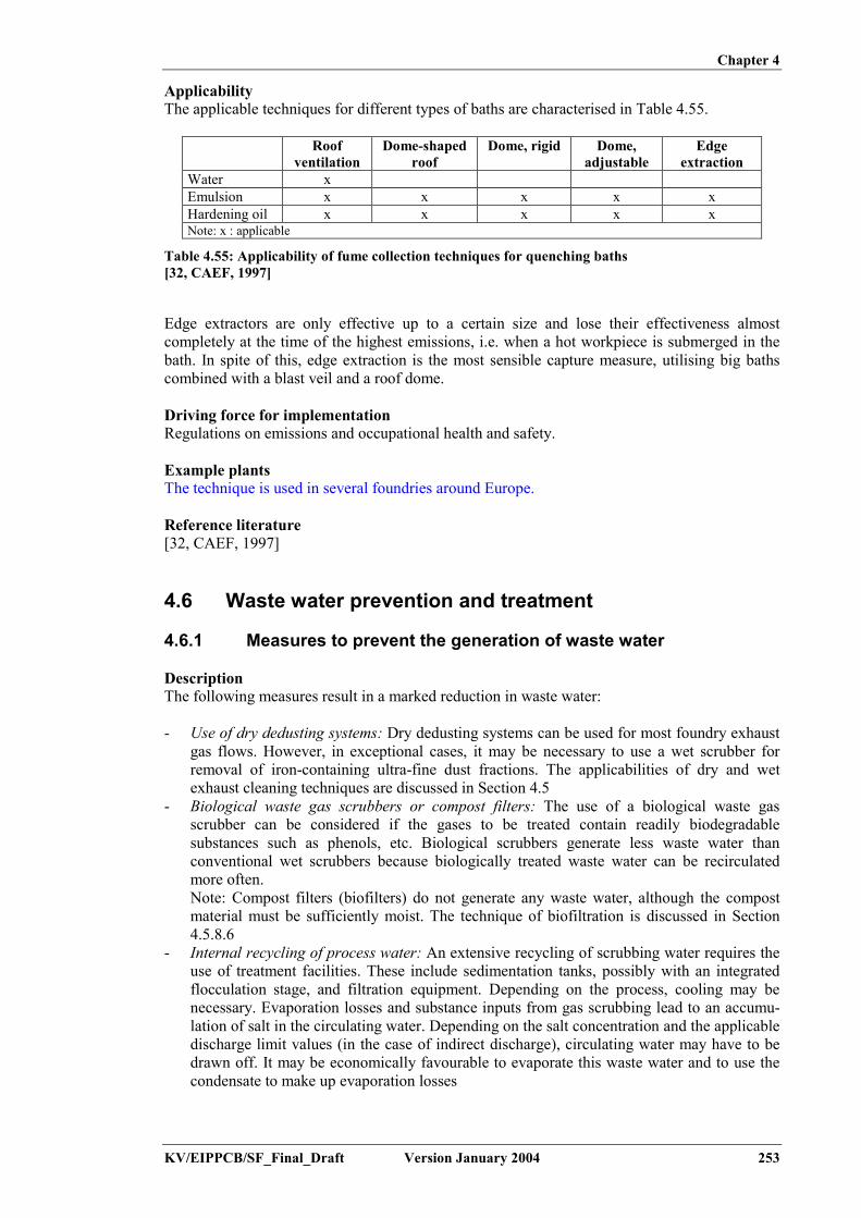
Chapter 4
KV/EIPPCB/SF_Final_Draft Version January 2004 253
ApplicabilityThe applicable techniques for different types of baths are characterised in Table 4.55.
Roofventilation
Dome-shapedroof
Dome, rigid Dome,adjustable
Edgeextraction
Water xEmulsion x x x x xHardening oil x x x x xNote: x : applicable
Table 4.55: Applicability of fume collection techniques for quenching baths[32, CAEF, 1997]
Edge extractors are only effective up to a certain size and lose their effectiveness almostcompletely at the time of the highest emissions, i.e. when a hot workpiece is submerged in thebath. In spite of this, edge extraction is the most sensible capture measure, utilising big bathscombined with a blast veil and a roof dome.
Driving force for implementationRegulations on emissions and occupational health and safety.
Example plantsThe technique is used in several foundries around Europe.
Reference literature[32, CAEF, 1997]
4.6 Waste water prevention and treatment
4.6.1 Measures to prevent the generation of waste water
DescriptionThe following measures result in a marked reduction in waste water:
- Use of dry dedusting systems: Dry dedusting systems can be used for most foundry exhaustgas flows. However, in exceptional cases, it may be necessary to use a wet scrubber forremoval of iron-containing ultra-fine dust fractions. The applicabilities of dry and wetexhaust cleaning techniques are discussed in Section 4.5
- Biological waste gas scrubbers or compost filters: The use of a biological waste gasscrubber can be considered if the gases to be treated contain readily biodegradablesubstances such as phenols, etc. Biological scrubbers generate less waste water thanconventional wet scrubbers because biologically treated waste water can be recirculatedmore often.Note: Compost filters (biofilters) do not generate any waste water, although the compostmaterial must be sufficiently moist. The technique of biofiltration is discussed in Section4.5.8.6
- Internal recycling of process water: An extensive recycling of scrubbing water requires theuse of treatment facilities. These include sedimentation tanks, possibly with an integratedflocculation stage, and filtration equipment. Depending on the process, cooling may benecessary. Evaporation losses and substance inputs from gas scrubbing lead to an accumu-lation of salt in the circulating water. Depending on the salt concentration and the applicabledischarge limit values (in the case of indirect discharge), circulating water may have to bedrawn off. It may be economically favourable to evaporate this waste water and to use thecondensate to make up evaporation losses

Chapter 4
254 Version January 2004 KV/EIPPCB/SF_Final_Draft
- Multiple use of treated waste water: Multiple use of treated waste water needs to beconsidered, e.g. using process water from sand preparation in the moulding sand cycle or inslag granulation. The use of cooling water in wet scrubbing may also be considered
- Use of waste heat for the evaporation of waste water: This technique can only be appliedwhen waste heat is available on a continuous basis. A case-by-case evaluation is needed toevaluate its applicability and economic viability
- Prevention of waste water from scrap storage: The generation of waste water from thestorage of contaminated scrap can be prevented by roofing the storage area. The run-offwater is collected as uncontaminated rainwater. All techniques for storage are discussed inSection 4.1
- Avoidance of AOX formation in waste water: Careful selection of scrap types can preventthe uptake of chlorinated compounds in the production cycle. Analyses for AOXcompounds prior to scrap purchase are a helpful measure. AOX may also be contained inauxiliaries used in waste water treatment, e.g. commercial-grade hydrochloric acid, ironchloride or aluminium chloride
- Keep water types separate:Various water flows with distinct pollutant levels are keptseparate, in order to minimise the need for waste water treatment and to optimise the wateruse.
Achieved environmental benefitsPrevention of the production of waste water.
Cross-media effectsCross-media effects may apply, depending on the chosen technique. Information is given in thespecified sections.
Operational dataOperational data are given in the description of the example plant in Section 4.6.3.
The waste water system of an example aluminium foundry consists of 4 separate flows:- surface run-off: this joins to the central rainwater channel, through an oil separator
(2xNG80), and onto a nearby river- used water = process water (open cooling baths) and sanitary water: this goes through an
open air channel on site, into a public channel and then onto the public sewage works of thetown
- cooling water: this is initially taken from the nearby river, over a sand filter, and goesthrough the installation in a closed percolation cooling circuit, and then back to the river,with a temperature limited to 28 ºC. Roof water also enters the cooling water circuit
- water from off-gas scrubbers (green sand, post casting): this is partially evaporated, so thatonly the remaining sludge leaves the installation.
ApplicabilityThis technique applies to all new and existing installations.
EconomicsEconomic data are given in the specified sections for alternative techniques and in the ‘Exampleplants’ section of Section 4.6.3.
Driving force for implementationMinimisation of waste water production.
Example plantsHonsel, Meschede (D)
Reference literature[195, UBA, 2003]
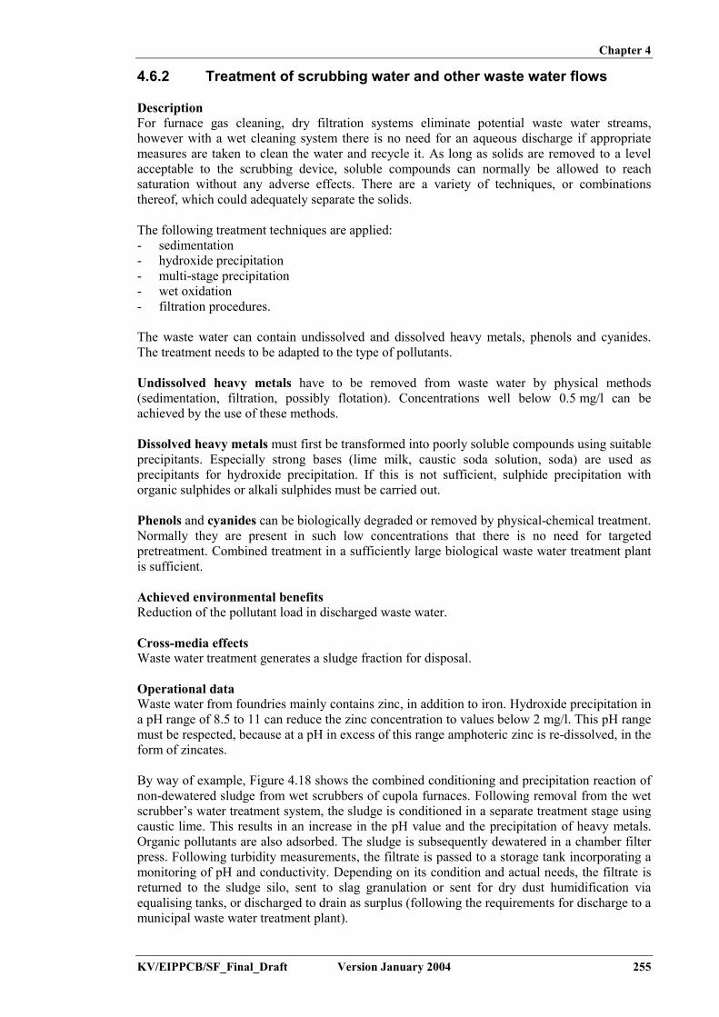
Chapter 4
KV/EIPPCB/SF_Final_Draft Version January 2004 255
4.6.2 Treatment of scrubbing water and other waste water flows
DescriptionFor furnace gas cleaning, dry filtration systems eliminate potential waste water streams,however with a wet cleaning system there is no need for an aqueous discharge if appropriatemeasures are taken to clean the water and recycle it. As long as solids are removed to a levelacceptable to the scrubbing device, soluble compounds can normally be allowed to reachsaturation without any adverse effects. There are a variety of techniques, or combinationsthereof, which could adequately separate the solids.
The following treatment techniques are applied:- sedimentation- hydroxide precipitation- multi-stage precipitation- wet oxidation- filtration procedures.
The waste water can contain undissolved and dissolved heavy metals, phenols and cyanides.The treatment needs to be adapted to the type of pollutants.
Undissolved heavy metals have to be removed from waste water by physical methods(sedimentation, filtration, possibly flotation). Concentrations well below 0.5 mg/l can beachieved by the use of these methods.
Dissolved heavy metals must first be transformed into poorly soluble compounds using suitableprecipitants. Especially strong bases (lime milk, caustic soda solution, soda) are used asprecipitants for hydroxide precipitation. If this is not sufficient, sulphide precipitation withorganic sulphides or alkali sulphides must be carried out.
Phenols and cyanides can be biologically degraded or removed by physical-chemical treatment.Normally they are present in such low concentrations that there is no need for targetedpretreatment. Combined treatment in a sufficiently large biological waste water treatment plantis sufficient.
Achieved environmental benefitsReduction of the pollutant load in discharged waste water.
Cross-media effectsWaste water treatment generates a sludge fraction for disposal.
Operational dataWaste water from foundries mainly contains zinc, in addition to iron. Hydroxide precipitation ina pH range of 8.5 to 11 can reduce the zinc concentration to values below 2 mg/l. This pH rangemust be respected, because at a pH in excess of this range amphoteric zinc is re-dissolved, in theform of zincates.
By way of example, Figure 4.18 shows the combined conditioning and precipitation reaction ofnon-dewatered sludge from wet scrubbers of cupola furnaces. Following removal from the wetscrubber’s water treatment system, the sludge is conditioned in a separate treatment stage usingcaustic lime. This results in an increase in the pH value and the precipitation of heavy metals.Organic pollutants are also adsorbed. The sludge is subsequently dewatered in a chamber filterpress. Following turbidity measurements, the filtrate is passed to a storage tank incorporating amonitoring of pH and conductivity. Depending on its condition and actual needs, the filtrate isreturned to the sludge silo, sent to slag granulation or sent for dry dust humidification viaequalising tanks, or discharged to drain as surplus (following the requirements for discharge to amunicipal waste water treatment plant).

Chapter 4
256 Version January 2004 KV/EIPPCB/SF_Final_Draft
Sludge/waste water from wet process dust separator and
Coagulation aid
Lime
Storage tankAir
Sludge silo
Conductivity andpH-value measuring
Turbidimetry
Filter press
Waste water
Storage tankfor filtrate
Equalising tank for filtrate
To dross granulation
To the humidification of dry dust
Figure 4.18: Treatment of waste water and sludge from the wet de-dusting system of a cupolafurnace[195, UBA, 2003]
Additional operational data are given in the description of the example plant in Section 4.6.3.
ApplicabilityThe type of waste water treatment to be applied needs to be selected on the basis of the wastewater composition and the local conditions for disposal of water from the plant into thereceiving water medium.
EconomicsEconomic data are given in the description of the example plant in Section 4.6.3.
Driving force for implementationRegulations for pollutants discharge into water.
Example plantsSee Section 4.6.3
Reference literature[195, UBA, 2003], [160, UK Environment Agency, 2002]
4.6.3 Example plant for waste water prevention and reduction
DescriptionA German example plant produces parts from cast iron (grey and nodular cast iron) and die-castaluminium.The following operations are carried out:- Melting: Gas-fired melting furnaces and flue-gas treatment plant (dry filter)- Manufacture of diecast parts: Automated casting-punching cells for aluminium diecasting- Sand casting: Manufacture of special alloys- Iron casting (core production): For core production, the cold-box and Croning processes
are used. Scrubbing concentrates are generated in amine scrubbing- Iron casting (melting): The melting shop consists of a mixing plant, a hot blast cupola
furnace, several electric furnaces, a converter and a holding furnace- Iron casting (moulding): Use of lost moulds made of bentonite-bonded sand.

Chapter 4
KV/EIPPCB/SF_Final_Draft Version January 2004 257
Production data and water consumption are given in Table 4.56.
ProductionGood iron castings, total 46710 tGood non-ferrous metal castings, total 2355 tWater consumptionDrinking water (town water) 59630 m3
Surface water/groundwater 64998 m3
Table 4.56: Production and water consumption data (on yearly basis) for example foundry[195, UBA, 2003]
Wet scrubbers are applied where large volumes of waste gas containing relatively highconcentrations of organic substances are generated (waste gas from core-making) or where highflue-gas temperatures occur (flue-gas from hot-blast cupola furnaces).
A schematic representation of the water circuit of the wet dedusting system is given in Figure4.19. The waste gas from under-charge cupola flue-gas extraction is fed to a cyclone separatorand a venturi scrubber for dedusting. The subsequent removal of gaseous pollutants is achievedin a packed bed scrubber. The waste water from the venturi scrubber is pretreated in a float andsink separator and then passed to a settling tank for secondary treatment. The scrubbing liquidfrom the packed tower is fed directly into the settling tank. The settled sludge from the settlingtank can be pumped discontinuously to the float and sink separator. The sludge from the floatand sink separator is pumped to a scraper conveyor, agglomerated by the addition of flocculants,and passed into a storage tank. From there, the sludge is fed to the sludge silo and issubsequently solidified in a mixing plant by the addition of dry dust.

Chapter 4
258 Version January 2004 KV/EIPPCB/SF_Final_Draft
Packed bedscrubber
Srubber DSSS
FA
AirScraper conveyor
Settingtanks
Dry dust Sludge silo
Mixer
Figure 4.19: Water circuit for the wet dedusting system of a cupola furnaceDSSS: double shell sinking separator; FA: flocculant, M: motor[195, UBA, 2003]
In this basic layout, the plant experienced some operational problems, due to salt accumulationand the low final water quality. An extension was made to the plant, with the aims of:- increasing the settling velocity, by the use of other flocculants- reducing the pollutant content in the scrubbing medium- improving sludge dewatering- re-using the scrubbing medium from the gas scrubbing cycle.
For this purpose, a chamber filter press with a volume of 2 m3 and a sludge collection tank(30 m3 in volume) with an agitator were installed. The sludge was passed from the scraperconveyor directly into the storage tank and preconditioned with lime.
During the trial phase, which lasted several months, it was found that approximately 25 kg oflime per batch were needed to achieve the best result in terms of dewatering and heavy metalremoval. The average dry matter content was 70%. Analysis of the filtrate for heavy metalsshowed values in the range of detection limits. However, the relatively high sulphateconcentrations of about 1 g/l posed a problem for re-use of the filtrate in the scrubbing cycle.

Chapter 4
KV/EIPPCB/SF_Final_Draft Version January 2004 259
As a practicable alternative, the sludge treatment was further extended with other compounds asshown in Figure 4.20. The water/solids mixtures from wet scrubbing were pre-conditioned bythe addition of flocculant and the resulting sludge was fed to a mixing tank by a scraper. Lime isadded to the mixing tank in a quantity which needs to be determined previously through tests,and the sludge is fed to the sludge silo by a pump (pump P1 in Figure 4.20). Pump P2 pumps itto the filter press.
The filtrate is passed via a turbidity meter into a storage tank in which pH and conductivity aremonitored. There are three possibilities for where it goes from there:- via an equalising tank to slag granulation or dry dust humidification- back to the sludge silo (if the turbidity limit is exceeded)- to drain (emergency measure only).
Sludge silo
Sludge/waste water from wetdedusting and cleaning
Lime
Flocculant
Air
Filter-press Turbidity
P 1
P 2
P 4
P 5 Pumping chamber for filtrate
Channel
V 3V 1
V 2
Buffer for filtrate
To dry dust humidification
To slag granulation pH, conductivity
Figure 4.20: Treatment system for sludge from the wet dedusting of cupola flue-gas[195, UBA, 2003]
EconomicsEconomic data concerning the extension of the system with the sludge treatment are given inTable 4.57.
Before extension After extensionGenerated sludge with a drymatter content of 30%
2000 t/yr Generated sludge with a drymatter content of 70%
850 t/yr
Dry dust for sludgesolidication
1100 t/yr Dry dust for sludgesolidication
0 t/yr
Landfill price EUR 100/t Landfill price EUR 100/tDisposal costs per year EUR 310000 EUR 85000
Table 4.57: Disposal costs for the extension of a waste water system with sludge treatment[195, UBA, 2003]
The sludge with 70 % dry matter content does not need further stabilisation before disposal. Forthe wet sludge, a solidification with dry dust is needed. The saving in disposal costs isEUR 310000 – EUR 85000 = EUR 225000. This compares to an investment cost for theextension totalling EUR 175000 and an additional annual operating costs of about EUR 50000.

Chapter 4
260 Version January 2004 KV/EIPPCB/SF_Final_Draft
The total cost saving therefore amounts to EUR 175000/yr, giving a 1-year payback period. Thecalculation does not include the cost savings from the re-use of the filtrate.
Example plantsSach Giesserei GmbH, Kitzingen (D).
Reference literature[195, UBA, 2003]
4.6.4 Oil interceptors
DescriptionRun-off from all open areas, but particularly from raw materials stocking areas, containsuspended solids, which can be removed by settlement or other techniques. Oil interceptors areused in draining scrap handling areas. Drainage sumps are designed with a sufficient size tohandle storm-water and to accommodate any storm surge, in order to prevent carry-over ofunsettled material.
Oil interceptors are used on waste water from permanent mould casting foundries. Thehydraulic systems of die casting automates can potentially leak oil. The water collection systemis thus designed in such a way that any oil from leakage is collected and the resulting wastewater flow is treated using an oil interceptor.
Achieved environmental benefitsPrevention of water pollution.
Cross-media effectsOil interception generates a residue for disposal.
ApplicabilityThis technique applies to new and existing die-casting (permanent mould) foundries and to allother foundries with a waste water discharge directly to surface water.
Driving force for implementationRegulations for pollutants discharge into water.
Example plantsHonsel, Meschede (D).
Reference literature[160, UK Environment Agency, 2002]
4.6.5 Recovery of amine from scrubbing water
DescriptionWhen acid washing the cold-box exhaust gas, amine sulphate is formed (see Section 4.5.8.4).This amine may be recovered through neutralisation with sodium hydroxide, followed bydistillation.
As shown in Figure 4.21, the salt that is formed from tertiary amine (e.g. DMEA, DMIA andtriethanolamine (TEA)) in the acid scrubber, and the scrubbing acid (e.g. sulphuric acid) areretransformed by reaction with a strong base (e.g. caustic soda solution), thereby forming freeamine and e.g. sodium sulphate. The amine is expelled with water vapour and is then cleanedand concentrated in a column, to an extent that allows it to be re-used. The sodium sulphatesolution (together with polluted scrubbing solution) can be recovered or may be disposed of.

Chapter 4
KV/EIPPCB/SF_Final_Draft Version January 2004 261
If the amine is not recycled, the scrubbing concentrates can be treated in a biological wastewater treatment plant with nitrogen elimination.
Wet scrubber liquid
Storage tank
Storage tankColumn
CondensatorNaOH
Emission condensatorWaste air to theamine scrubber
Brine
TankTankTank
Brine Brine
Steam
Water Dischargeof amine
Dischargeof amine
Na2SO4
Figure 4.21: Amine recycling plant[195, UBA, 2003]
Achieved environmental benefitsRecovery of a chemical compound, which may be re-used.
Cross-media effectsIf the operation is performed in a centralised plant, it involves transport of the scrubber liquid tothe treatment unit.
ApplicabilityThis technique is applicable to all amine-containing scrubber liquors from core-making exhaust.The implementation is limited by economic factors (e.g. transport costs), since sufficientquantities of amine scrubber liquid need to be available. In general, the treatment is applied in acentralised location, treating the effluents of several foundries. Since the operation is subject toan explosion hazard, any necessary measures to prevent explosion risks should be taken.
Driving force for implementationRecovery of chemical compounds. Disposal costs for industrial waste.
Example plants- Centralised recycling plants Voerde (D)- Centralised plant for group of automotive foundries: Poitou (F).
Reference literature[195, UBA, 2003]

Chapter 4
262 Version January 2004 KV/EIPPCB/SF_Final_Draft
4.6.6 Reduction of glycols in die-casting waste water streams
DescriptionHydraulic systems for die-casting use water-glycol mixtures, such as hydraulic liquid. Leaks inthe hydraulic system and consequent transport of the leaked liquid into the water system couldlead to the presence of glycols in the foundry waste water. Removal of the glycol is not possibleusing filtration or flotation techniques.
The applicable treatment techniques are:- distillation or vacuum evaporation- biological degradation.
The cleaned waste water may be re-used as a solvent for the release agent.
Achieved environmental benefitsReduction of water pollution.
Cross-media effectsIn the waste water treatment, a sludge cake is produced and needs disposal.
Operational dataIn an example Belgian foundry, process water is treated in a vacuum evaporation unit (capacity3 m³/day). Three sources feed the unit: excess release agent (collected under the HPDC units),leakage hydraulic fluid from casting automates (water + glycol), and water from E-filtercleaning. The vacuum evaporation produces a sludge cake for disposal and an effluent. Theeffluent has a high COD and a low hardness (alkalinity). This makes it well suited for re-use asa solvent for the release agent.
ApplicabilityThis technique applies to all new and existing die-casting foundries.
Driving force for implementationRegulation for pollutant discharge into water.
Example plantsMetaalgieterij Giessen, Hoboken (B): aluminium foundry using HPDC and gravity die-casting.
Reference literature[202, TWG, 2002]
4.7 Energy efficiency
4.7.1 Introduction
Metal melting and the holding of molten metal in the molten state generally take up a significantpart of a foundry’s energy consumption. In many foundries more energy is used in holding themetal in the molten state than in the actual melting process. Furthermore, considerable energy isexpended in areas other than that of metal supply. For example, foundries are generally largeusers of compressed air. Other large users of energy are likely to be items such as high-pressuredie-casting machines, whose mainly hydraulic power units are also driven by electricity. Sandand gravity die foundries may employ hot core-making processes, such as shell or hot-box,using gas or electricity to heat the boxes. The heating of dies and ladle and furnace linings canamount to an appreciable fraction of the total energy used. The typical relative distribution ofenergy use in two foundry types is given in Table 4.58.[64, ETSU, 1997]

Chapter 4
KV/EIPPCB/SF_Final_Draft Version January 2004 263
Activity Non-ferrous foundry(%)
EAF steel foundry(10000 t/yr good casting)
(%)Melting 30 44Holding 30Plant actuation 15Air compression 14 10Tool heating 3Heat treatment (gas) 7Others * 8 39(*) Includes all activities for which no values are given in the same column and activitieswhich are not mentioned
Table 4.58: Typical energy use in a non-ferrous and EAF steel foundry[64, ETSU, 1997], [202, TWG, 2002]
These data show that foundry services (i.e. all but melting and holding) are responsible for up tohalf of foundry energy consumption. This includes activities using items such as motors anddrives, compressed air, lighting, space heating and boiler plant. Energy efficiency measuresshould have regards to both the melting and the services field. [46, ETSU, 1995]
Energy efficient operation is brought about by applying good practice measures to reduceenergy use in all of the mentioned steps. Improved energy efficiency is one of the mainenvironmental benefits mentioned throughout the techniques discussions this chapter. Thefollowing sections focus on specific techniques aimed at heat recovery and heat transfer to otherparts of the foundry.
4.7.2 Induction furnace: waste heat utilisation
DescriptionA significant proportion of the electrical energy which is supplied to an induction-meltingfurnace is converted into waste heat. About 20 to 30 % of the total energy input to the plant isdissipated through the cooling system. The furnace cooling circuit not only deals with theelectrical losses in the induction coil, but also protects the coil from heat conducted through thefurnace lining from the hot metal in the crucible. The heat in the furnace cooling system is usedin some installations for space-heating, the heating of shower water and for drying rawmaterials.
- Drying of raw materials: Where metallic charge materials are added to a molten heel in aninduction-melting furnace, the presence of water in the scrap can potentially be verydangerous. Although scrap may be stored under cover at the foundry, it is possible that itmay be wet when delivered by the scrap dealer. The heat in the furnace cooling water canbe extracted in an air/water heat-exchanger and a fan can be used to convey the warmed airto the bases of the stockyard bunkers. A diagrammatic layout of such an installation isshown in Figure 4.22.
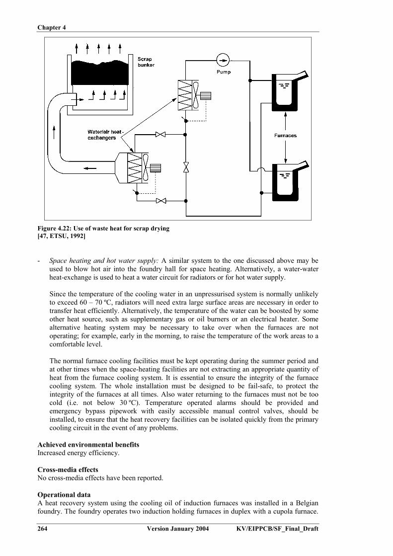
Chapter 4
264 Version January 2004 KV/EIPPCB/SF_Final_Draft
Figure 4.22: Use of waste heat for scrap drying[47, ETSU, 1992]
- Space heating and hot water supply: A similar system to the one discussed above may beused to blow hot air into the foundry hall for space heating. Alternatively, a water-waterheat-exchange is used to heat a water circuit for radiators or for hot water supply.
Since the temperature of the cooling water in an unpressurised system is normally unlikelyto exceed 60 – 70 ºC, radiators will need extra large surface areas are necessary in order totransfer heat efficiently. Alternatively, the temperature of the water can be boosted by someother heat source, such as supplementary gas or oil burners or an electrical heater. Somealternative heating system may be necessary to take over when the furnaces are notoperating; for example, early in the morning, to raise the temperature of the work areas to acomfortable level.
The normal furnace cooling facilities must be kept operating during the summer period andat other times when the space-heating facilities are not extracting an appropriate quantity ofheat from the furnace cooling system. It is essential to ensure the integrity of the furnacecooling system. The whole installation must be designed to be fail-safe, to protect theintegrity of the furnaces at all times. Also water returning to the furnaces must not be toocold (i.e. not below 30 ºC). Temperature operated alarms should be provided andemergency bypass pipework with easily accessible manual control valves, should beinstalled, to ensure that the heat recovery facilities can be isolated quickly from the primarycooling circuit in the event of any problems.
Achieved environmental benefitsIncreased energy efficiency.
Cross-media effectsNo cross-media effects have been reported.
Operational dataA heat recovery system using the cooling oil of induction furnaces was installed in a Belgianfoundry. The foundry operates two induction holding furnaces in duplex with a cupola furnace.

Chapter 4
KV/EIPPCB/SF_Final_Draft Version January 2004 265
The inductors of the electrical furnaces are cooled using thermal oil. The thermal oil gets heatedup to 200 – 300 ºC and looses its heat over an outside oil-air heat-exchanger. Before installationof the heat recovery system, 1 MW of heat was dissipated into the air. An alternative systemwas installed to use the waste heat for space heating. The heated air is introduced into the coreshop. This allows the recuperation of 1/3 of the dissipated heat and replaces the original gas-fired heating system. The implementation was possible at low cost because the oil-air heat-exchanger is installed next to the core shop. Space heating in other parts of the foundry may beconsidered later, but will require more piping (and will subsequent thus involve further losses).
ApplicabilityBefore heat recovery can be applied, a number of criteria must be met:
- a worthwhile application for the waste heat must be reasonably nearby and the times atwhich this recovered heat can be utilised must match the times at which the furnace isoperating. However, typically the heat available is fairly low grade. The temperature for thecooling water must not exceed 70 ºC
- the relatively low temperatures involved mean that heat-exchangers need to be much largerthan those which are normally encountered
- the furnace water must not be returned to the furnaces at a temperature lower than about30 ºC, otherwise this may give rise to condensation problems
- maintaining the integrity of the cooling circuits is absolutely essential. The cooling circuit isprovided to protect the coil - if it fails in its task the results can be disastrous.
The above aspects, particularly the question of furnace integrity, discourage most furnaceoperators from even contemplating the utilisation of heat from the cooling circuit.
EconomicsA foundry attempting to make use of the heat from the cooling circuit needs to fully evaluate thebenefits and then compare them with the cost of the additional equipment and the safety of thefurnace and operators.
Driving force for implementationIncreasing energy efficiency at the foundry.
Example plantsSpace heating using hot air: Proferro, Oudenaarde (B).Metso Paper Jyväskylä Foundry (F).
Reference literature[47, ETSU, 1992]
4.7.3 Cupola furnace: waste heat utilisation
DescriptionThe need to cool cupola off-gases before they enter the bag filter leads to the possibility ofattaching to a secondary user and applying waste heat utilisation. The secondary user may bee.g.:- a steam boiler- a thermal oil circuit- a heating circuit- a hot water circuit.
Achieved environmental benefitsRecovery of waste heat, which otherwise would be lost to the outside, allowing a reduction infuel (or other sources of energy) consumption.

Chapter 4
266 Version January 2004 KV/EIPPCB/SF_Final_Draft
Cross-media effectsNo cross-media effects apply.
Operational dataThe two example plants described in Section 4.5.2.2, are equipped with a waste heat utilisationsystem. Plant data have been given in Table 4.37.
Plant G uses cupola waste heat for electricity production. Part of the off-gas flow is fed to asteam boiler, which drives a turbine, coupled to a generator or compressor. A schematicrepresentation of the installation is given in Figure 4.23. In total 29 % of the introduced cokesheat is converted into additional utilisation. Around 2.9 MW of electrical energy are generated.This means that the plant generates an electrical power of 75 kWh/tonne liquid iron.
Figure 4.23: Schematic representation of a hot blast cupola with a steam boiler, turbine andgenerator[27, Kran, et al., 1995]
Plant H uses cupola waste heat in a thermal oil circuit. After heat exchange for blast preheating,the off-gas passes a gasoil heat-exchanger. The heated oil is used for core drying. A maximumheat recovery of 21 MW can be attained. A process flow diagram is given in Figure 4.24.

Chapter 4
KV/EIPPCB/SF_Final_Draft Version January 2004 267
Figure 4.24: Process flow diagram of a hot blast cupola with heat recovery[17, Strauß, 1983]
ApplicabilityThis technique applies to new installations and should be taken into account when designing theprocess. For existing plants, the technique can be applied during major refurbishment of theplant, however, small add-on units can generally be accomodated in existing plants.
EconomicsThe stated examples were installed as part of a major rebuilding of the considered installation. Itis therefore not possible to extract specific cost data.
Driving force for implementationIncreasing energy efficiency of industrial processes.
Example plantsThe two mentioned example plants are located in Germany.
Reference literature[17, Strauß, 1983], [27, Kran, et al., 1995], [202, TWG, 2002]
4.7.4 Reduce energy loss/improve preheating practice of ladles
DescriptionEnergy is wasted if the molten metal transfer system allows an excessive loss of metaltemperature between furnace tapping and mould pouring. Losses can be prevented by usinggood practice measures. These imply the following:- the utilisation of clean ladles, preheated to bright red heat- the utilisation of distribution and pouring ladles, which are as large as is practicable and are
fitted with heat-retaining covers- keeping the covers on ladles which are standing empty or putting ladles upside down when
not in use- minimising the need to transfer metal from one ladle to another- always conveying the metal as quickly as possible, while still complying with safety
requirements.

Chapter 4
268 Version January 2004 KV/EIPPCB/SF_Final_Draft
Achieved environmental benefitsTo reduce energy losses.
Cross-media effectsNo cross-media effects occur.
ApplicabilitySince this technique involves measures related to good practice, it is applicable to all new andexisting foundries.
EconomicsNo economic data can be given.
Driving force for implementationEnergy efficient foundry management.
Example plantsThese measures are used to a varying extent in European foundries.
Reference literature[44, ETSU, 1993]
4.8 Sand: regeneration, recycling, re-use and disposal
4.8.1 Introduction
Since foundries make intensive use of sand as an inert primary material, the regeneration of thissand is a major point of consideration as part of its environmental performance. A cleardistinction must be made between green sand and chemically-bonded sand. Green sand can beeasily reconditioned after use. Indeed, recirculated green sand shows a better technical qualitythan new sand. Most green sand foundries perform primary regeneration.
Primary regeneration, also known as attrition or particulation, involves breaking down the sandfrom moulds or cores back to its original grain size. This includes screening the sand, removingtramp metal, and separating and removing fines and over-sized agglomerates. The sand is thencooled before being sent for storage, returned to the sand system or blended with new sand. Atthis stage, the sand grains are likely to retain a partial coating of spent binder. This affects theamount of reclaimed sand that can be used to make moulds and, more particularly, cores. Newsand therefore has to be added to ensure that the sand mix produces adequate mould and corestrength and subsequenty aids good casting quality. Primary reclaimed sand is not generally ofsufficient quality to be used for core-making, without further processing to remove residualbinder materials, and is therefore used principally for moulds. The main primary regenerationtechniques are vibration, rotating drum or shot blasting.
Secondary regeneration involves the further processing of the previously particulated sand toremove residual binder. The sand is returned to a quality similar to, or better than, that of newsand. Foundries using secondary regeneration have, in some cases, virtually eliminated the needfor new sand. To remove residual binder, more aggressive techniques are needed than forprimary regeneration. The main secondary regeneration techniques are:- cold mechanical treatment:
� low energy attrition: friction, impact (for cold-setting resins)� high energy attrition: pneumatic chafing, grinding, centrifugal friction
- thermal treatment (usually in a fluidised bed)- wet scrubbing.

Chapter 4
KV/EIPPCB/SF_Final_Draft Version January 2004 269
Sands bonded with cold-setting resins may be regenerated using simple treatment techniques,due to the fragility of the binder layer. Mechanical regeneration systems (e.g. fluidised bedsystems) are based on interparticle friction or impact.
Sands bonded with gas-hardened and thermosetting resins need more intensive treatment toremove the binder layer. These include grinding, pneumatical chafing and centrifugal friction.Silicate sands can only be regenerated mechanically using pneumatical treatment.
Thermal treatment involves the burning of the organic binder. Bentonite is inactivated by thehigh treatment temperature. For sand flows containing green sand, any thermal treatment shouldtherefore be combined with a mechanical treatment.
Wet regeneration involves binder removal through interparticle grinding. This technique appliesonly for green sand and silicate or CO2-bonded sands and is not widely applied.
Secondary regeneration of green sand as a monosand flow finds limited implementation. Forchemically-bonded sands, mechanical regeneration is most widely applied (>200 units inGermany in 1999) [80, ERM Lahmeyer International GmbH, 1999]. The applicability of thevarious regeneration techniques and of the regenerated sand are summarised in Table 4.59(monosands) and Table 4.60 (mixed sand). Each of the presented techniques will be discussedin more detail in the sections below.
The most important monosand flows for secondary regeneration are the core sands in non-ferrous foundries. Due to the low thermal load they are easily separated from the green sand.Furthermore monosands are produced from mould and core-making with purely organicsystems such as croning, furan resin and urethane cold-box. A smaller monosand stream is non-cured core sand, arising from broken or rejected cores in the core-making shop and the residualsand of core-making machines.
Mixed sands generally contain bentonite-bonded sand as well as chemically-bonded sand. Theyare mainly generated in iron foundries and represent some 75 % of the total waste sandproduction.

Chapter 4
270 Version January 2004 KV/EIPPCB/SF_Final_Draft
Type of sand Regenerationtechnique
Regenerationequipment
Utilisation Borderline conditions Minimalquantity(tonne/h)
OrganicmonosystemsCold-settingresins
Mechanical orthermal
Mechanical:friction, impact,pneumatic chafingThermal: turbulentbed, fluidised bedor rotary furnace
- for mould-making usingcold-settingresins
- 20 – 25 %substitution ofnew sand forcold-settingcore-making
- mechanical: only ifbinder shells havebecome fragile enoughupon pouring
- the target values forregenerate qualitymust be met
1.5
Cold-Box,SO2, Hot-Boxand Croningsand
Mechanical orthermal
Mechanical:pneumatic chafing,centrifugal friction,fluidised bedchafingThermal: turbulentbed, fluidised bedor rotary furnace
In core-making,as new sandsubstitute
- mechanical: only ifbinder shells havebecome fragile enoughupon pouring
- the orientative valuesfor regenerate qualitymust be met
- re-use of fines
0.75
Resol- estermethylformatehardenedsand
Mechanical Mechanical:friction, impact,pneumatic chafing
With limitations,in mould-making withmethyl formatesands
- regeneration as resol-ester cold setting butwith lower yield
- embrittlement ofbinder components
InorganicmonosystemsGreen sand Mechanical pneumatic chafing,
grindingRenewal sandfor green sandcircuit
- requires predrying- re-use of fines
0.75
Sodiumsilicate sand
Mechanical Only for makingmoulds andcores usingsodium silicatesand
Embrittlement of bindercomponents at 200 ºC
0.5
Table 4.59: Fields of application of different regeneration systems for monosands[128, IHOBE, 1998], [225, TWG, 2003]
Type of sand Regenerationtechnique
Regenerationequipment
Utilisation Borderline conditions Minimalquantity(tonne/h)
Mixedorganicsystems
Mechanical orthermal
Mechanical:pneumatic chafing,centrifugal friction,fluidised bedchafingThermal: turbulentbed, fluidised bed orrotary furnace
- core-makingsubstitutingnew sand
- mechanical: only ifbinder shells havebecome fragileenough upon pouring
- the orientative valuesfor regenerate qualitymust be met
- re-use of fines
0.75
Mixed sandscontainingbentonite
Mechanical ormechanical-thermal-mechanical
Mechanical:grinding, pneumaticchafing, fluidisedbed chafingThermal: turbulentbed, fluidised bed orrotary furnace
- core-makingsubstitutingnew sand
- renewal sandfor the greensand circuit
- require pre-drying- combined thermal
regeneration requiresefficient mechanicalregeneration toremove activebentonite
- re-use of fines
0.75
Table 4.60: Fields of application of different regeneration systems for mixed sands[128, IHOBE, 1998]

Chapter 4
KV/EIPPCB/SF_Final_Draft Version January 2004 271
The applicability of the various treatment systems is summarised in Table 4.61 and will bediscussed further in the specific applicability sections.
Cold mechanical
Sim
ple
mec
hani
cal s
yste
ms
Grin
ding
Impa
ctdr
um
Pneu
mat
icch
afin
g
Wet
rege
nera
tion
Ther
mal
Mec
hani
cal –
ther
mal
–m
echa
nica
l
MonosandsCold setting x x x x x x 0Cold-box, SO2, Hot-box, Croning 0 x x x 0 x 0Silicate (CO2 or ester) 0 0 0 x x 0 0Green sand (primary) x 0 0 0 0 0 0Green sand (secondary) 0 x 0 x x 0 0Mixed sandsMixed organic 0 x x x 0 x 0Mixed green + organic 0 x 0 x x 0 xx: Applicable; 0: Not applicable
Table 4.61: Applicability of various sand regeneration techniques to various sand types
The application of both primary and secondary regeneration in a mixed sand foundry in order toachieve a total regeneration of 92 % is shown in Figure 4.25. This simplified scheme does nottake into account the various losses in the processing steps. The addition of new sand can bereduced to a minimum by integrating (the coarse fraction of) the filter dust sands (from theexhaust of hand forming lines, de-coring lines, storage silos, etc).
Figure 4.25: Sand balance diagram for a thermal/mechanical regeneration system[70, ETSU, 1998]

Chapter 4
272 Version January 2004 KV/EIPPCB/SF_Final_Draft
An overall reclamation ratio of 92 %, as given above, is a normal value for mixed green sand –chemically bonded sand systems. Regeneration ratios of up to 98 % have been reported. Theactual ratio depends on the volume and chemical composition of the used cores. For furan coldsetting monosands, values around 78 % are reported.
Generally the mixing of different types of sands has a negative effect on the strength of thecores and subsequently the moulds made with the regenerated sand, although there are a fewexceptions to this general principle. In order to produce a good quality regenerated sand it istherefore of great importance to keep non-compatible sand types separate. Optimisation of theregeneration potential may therefore imply changing to compatible binder systems, if mixedsands are used, or the application of (shake-out) techniques that allow the separation of varioussand types. Table 4.62 provides a cross-compatibility table.
Goal system Cold-box
Sour
cesy
stem
Bentonite Silicate Cold-setting
Hot-box Croning Methyl-
formateAmine SO2
Bentonite + 0 0 - 0 0 0 0Silicate 0 + - - - - - -Cold-setting + - + - 0 - 0 +Hot-box 0 - + + + - 0 +Croning + + + + + + + +
Methyl-formate
0 + 0/- - - 0 0 -
Amine + + + + + 0 + +Col
d-bo
x
SO2 + - + - 0 0 + ++: Compatible, 0: Limited compatibility, -: Incompatible
Table 4.62: Compatibility of regenerated sources sands with various binders[37, Winterhalter, et al., 1992], [225, TWG, 2003]
[37, Winterhalter, et al., 1992], [70, ETSU, 1998], [128, IHOBE, 1998], [138, MetaalgieterijGiesen B.V., 1996], [153, Umweltbundesamt, 2002], [202, TWG, 2002], [225, TWG, 2003]
4.8.2 Regeneration of green sand under optimised conditions(primary regeneration)
DescriptionOne of the major advantages in using green sand moulding is that the sand from the moulds canbe reconditioned after pouring for multiple re-use. The addition of a minimum percentage ofnew sand is performed in order to maintain the quality of the moulding-sand. The amount ofnew sand added is determined by the input of core sand and the losses in the process. Forcoreless moulding, the average sand renewal ratio is 2 – 5 %. In casting processes using cores,sand renewal occurs through the introduction of the core sand into the loop. In any case, surplussand is removed from the sand circuit after the shake-out screen or from the storage silos. Thegeneral treatment is depicted in Figure 2.28. This internal recirculation of green sand withminimal treatment is referred to as primary regeneration. This regeneration basically has threeaims: (1) to break the sand into its original grain size or small particles, (2) to remove the fines,and (3) to cool the sand before blending with new sand.
Various techniques are applied for the breaking and separation:- Vibration: The vibratory grid, or screen equipment, is the most widely used technique for
primary reclamation purposes. The sieved sand is removed for subsequent treatment, e.g.for cooling, size classification, and thermal reclamation, and the residual material iscollected for disposal

Chapter 4
KV/EIPPCB/SF_Final_Draft Version January 2004 273
- Drum: Sand from the knock-out operation is loaded into a rotating drum fitted with bothlifting and travelling bars. As the sand travels along the drum, the rotating and lifting actioncauses the sand particles to grind against each other and break down to individual grains.The sand grains fall through screens at the end of the drum, while oversize and trampmaterials are removed for landfill disposal
- Shot blast: The mould and casting is loaded directly into the shot blast machine. The actionof the shot blast results in the complete disintegration of the mould and also cleans thesurface of the casting. The sand and shot are subsequently separated. However, thistechnique is not very common.
During cooling of the castings, the sand gets heated-up. In order to reach good sand mixingconditions, the sand needs to be cooled down to 40 – 45 ºC. Evaporative coolers are used withturbulent and fluidised beds, as well as heat-exchangers. If shake-out is done using the vibratingtransporters of revolving drums, the cooling can occur at the same time.
If a fluidised bed cooler is used, the drying air may be heated using gas or electricity. Theaverage treatment time in the bed is 10 minutes. In general, the sand enters the fluidised bedwith a humidity of 2 – 3 % and a temperature of 250 – 300 ºC. Temperature and humiditycontrol may be performed before the fluidised bed cooler with a subsequent addition ofcontrolled amounts of water. This allows minimisation of the amount of fines that are removedduring the fluidised bed drying. The fines contain bentonite that may be re-activated. The levelof humidity of the return sand needs to be kept between 2 and 2.2 % at 35 ºC. Consequently,during storage, the bentonite contained in the cooled and wet sand starts to activate and, duringthe mixing, the water and bentonite that need to be added are reduced, as is the cycle time.
A good homogenisation of the sand allows a constant sand quality and better and easier sandpreparation. Homogenisation systems consist of the use of a few small silos instead of one bigone, or in the re-circulation of the sand in the silo.
In systems using chemically-bonded cores, the mixing of the core sand may have a negativeeffect on the sand quality, depending on the binder type and the amount of core sand mixed. Thenegative effects are more significant with acidic and alkaline cores, than compared to neutralsystems (SO2-epoxy, PUR-cold-box). During shake-out, core sand and moulding sand willinevitably get mixed. Uncured cores and non-broken cores, however, may be left out or takenout of the sand before feeding back to the primary regeneration.
Achieved environmental benefitsReduced usage of primary materials (sand and bentonite), reduced amount of material fordisposal.
Cross-media effectsSand regeneration uses electricity, therefore it increases the overall electric energy consumptionof the installation. Since mechanical techniques are mainly applied, this increase is low.Sand cooling and the separation of fines leads to dust-laden exhaust gas. The exhaust needs tobe filtered to prevent dust emissions. The collected dust is sent to disposal or re-used (seeSection 4.8.12).
Operational dataWhile the level of new sand addition is governed by a number of factors, the usual range is10 - 20 % of the poured metal weight. However, it is more convenient to consider new sandadditions as a percentage of sand throughput. For most foundry processes, a 5 % addition isconsidered sufficient, but many foundries work at lower rates.
For a green sand monosystem, regeneration ratios of 98 % may be achieved. Systems with ahigh degree of incompatible cores, may achieve a regeneration ratio of 90 – 94 %.
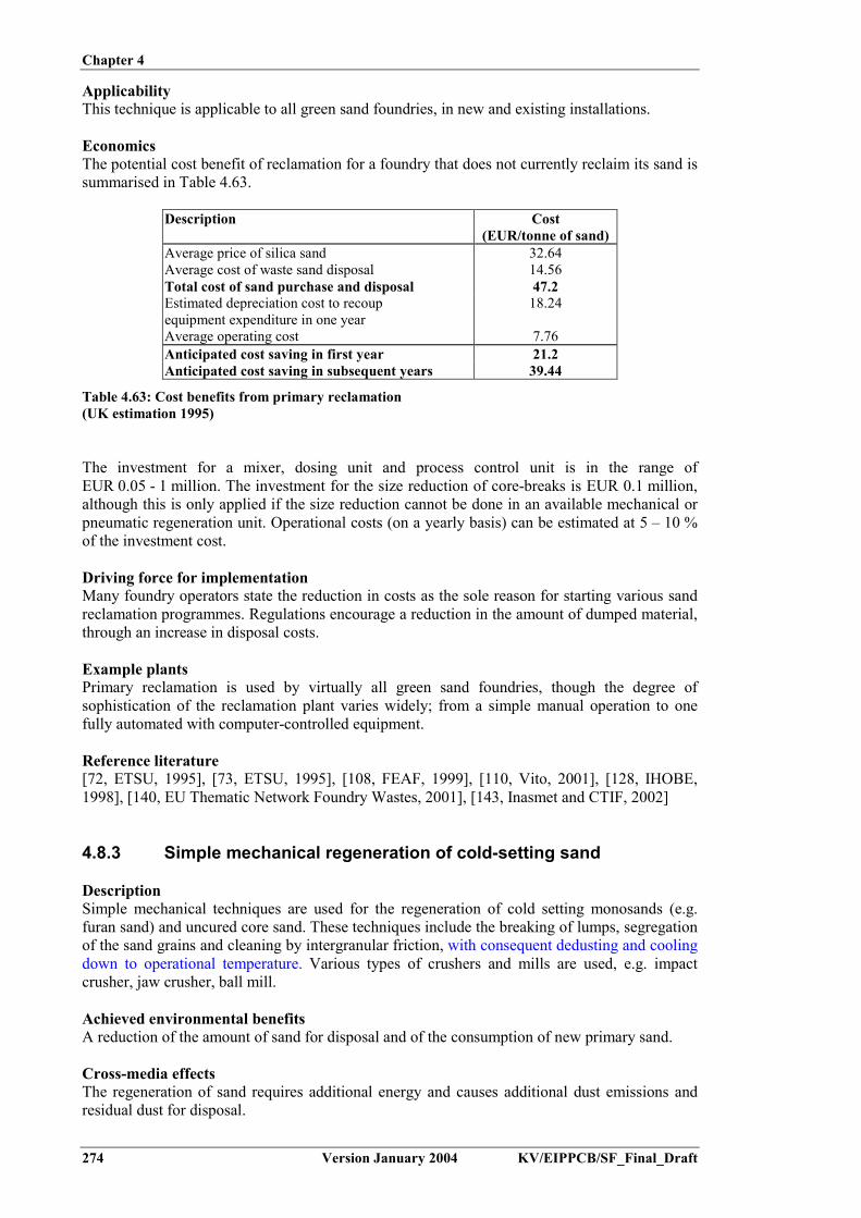
Chapter 4
274 Version January 2004 KV/EIPPCB/SF_Final_Draft
ApplicabilityThis technique is applicable to all green sand foundries, in new and existing installations.
EconomicsThe potential cost benefit of reclamation for a foundry that does not currently reclaim its sand issummarised in Table 4.63.
Description Cost(EUR/tonne of sand)
Average price of silica sand 32.64Average cost of waste sand disposal 14.56Total cost of sand purchase and disposal 47.2Estimated depreciation cost to recoupequipment expenditure in one year
18.24
Average operating cost 7.76Anticipated cost saving in first year 21.2Anticipated cost saving in subsequent years 39.44
Table 4.63: Cost benefits from primary reclamation(UK estimation 1995)
The investment for a mixer, dosing unit and process control unit is in the range ofEUR 0.05 - 1 million. The investment for the size reduction of core-breaks is EUR 0.1 million,although this is only applied if the size reduction cannot be done in an available mechanical orpneumatic regeneration unit. Operational costs (on a yearly basis) can be estimated at 5 – 10 %of the investment cost.
Driving force for implementationMany foundry operators state the reduction in costs as the sole reason for starting various sandreclamation programmes. Regulations encourage a reduction in the amount of dumped material,through an increase in disposal costs.
Example plantsPrimary reclamation is used by virtually all green sand foundries, though the degree ofsophistication of the reclamation plant varies widely; from a simple manual operation to onefully automated with computer-controlled equipment.
Reference literature[72, ETSU, 1995], [73, ETSU, 1995], [108, FEAF, 1999], [110, Vito, 2001], [128, IHOBE,1998], [140, EU Thematic Network Foundry Wastes, 2001], [143, Inasmet and CTIF, 2002]
4.8.3 Simple mechanical regeneration of cold-setting sand
DescriptionSimple mechanical techniques are used for the regeneration of cold setting monosands (e.g.furan sand) and uncured core sand. These techniques include the breaking of lumps, segregationof the sand grains and cleaning by intergranular friction, with consequent dedusting and coolingdown to operational temperature. Various types of crushers and mills are used, e.g. impactcrusher, jaw crusher, ball mill.
Achieved environmental benefitsA reduction of the amount of sand for disposal and of the consumption of new primary sand.
Cross-media effectsThe regeneration of sand requires additional energy and causes additional dust emissions andresidual dust for disposal.

Chapter 4
KV/EIPPCB/SF_Final_Draft Version January 2004 275
Operational dataFor furan cold setting monosands regeneration ratios around 78 % are reported.
ApplicabilityThe technique can be used for all cold-setting sand, excluding silicate sand. The regeneratedsand can be re-used in the same moulding cycle, with small additions of new sand to level-offquality losses.
The technique can be used for uncured coresand with organic binders. The regenerated sandmay be re-used for core-making using the same binder type, after mixing with new sand. It mayalso be used, within certain limits, for the renewal of moulding-sand.
Driving force for implementationLegislation using high disposal fees to reduce the amount of residues for disposal.
Example plantsSimple mechanical regeneration of furan sand is applied in many foundries around Europe, andis specifically widespread in Germany and Finland.
Reference literature[153, Umweltbundesamt, 2002], [202, TWG, 2002]
4.8.4 Cold mechanical regeneration using a grinding wheel unit
DescriptionThis is a widely applied commercial grinding system (see Figure 4.26). The system wasoriginally developed to regenerate mixed bentonite-organic sands. In this system, a horizontallyrotating grinding wheel is used to remove the hard oolitic bentonite layer from the sand. Thegrinding can also remove chemical binders from sand grains. Around the grinding wheel is aslowly rotating paddle wheel, which continuously moves the sand onto the grinding wheel.Above this, a dedusting unit extracts the dusts and the fines. To be fit for processing, the sandmust be dry. A pre-drying step, using a fluid bed or other dryer, is required to bring the moisturecontent down to below 0.2 %.
Figure 4.26: Cold mechanical regeneration using grinding[128, IHOBE, 1998]

Chapter 4
276 Version January 2004 KV/EIPPCB/SF_Final_Draft
The off-gas stream of the regenerator is dedusted using a cyclone and a bag filter. The filter dustcontains residual active bentonite and coal dust. It may be recirculated into the core-making,thereby allowing a reduction in the use of lustrous carbon. Furthermore, the moulds demonstratebetter technical quality (wet tensile strength, flowability), due to the remaining bentonitecontent, which furthermore leads to a reduction in the amount of scrap moulds and a reductionin finning on the castings.
Achieved environmental benefitsA reduction of the amount of sand for disposal and of the consumption of new primary sand.A reduction in the consumption of lustrous carbon, in the case of green sand.An increase in moulding sand properties, resulting in a reduction in the number of scrap mouldsand in the number of rejects in finished castings.
Cross-media effectsThe regeneration of sand requires additional energy and causes additional dust emissions andresidual dust for disposal. However, the use of regenerated sand in the moulding process allowsa reduction in the amounts of lustrous carbon used.
Operational dataFor clay-bonded sand, the maximum regeneration rate is 65 - 75 %. This corresponds to thequartz grain content of the material. For a chemically-bonded sand, the amount of recyclablequartz sand is 90 – 95 %.
The total sand circuit flow and the need for new sand depends on the amount of cores (and coresand) used. Therefore, data on the sand circuit are very process-specific. Figure 4.27 gives datafor a plant in the Netherlands.
Core shop Foundry
Scrap corebreaker
Sand cleaner
New sand70 kg
SiO2424 kg
Liquid iron1000 kg
Losses28 kg
396 kg
Losses42 kg354 kg
57 kg
Internal48 kg
External9 kg
Figure 4.27: Operational data on the sand circuit of a Dutch green sand foundry[140, EU Thematic Network Foundry Wastes, 2001]
In general, waste green sand consists of about 80 % quartz sand grains and about 20 % fines(bentonite, coal dust, etc,). Out of 100 % waste sand, about 70 % is transferred back to the core-making as reclaimed sand. The degree of efficiency with regard to quartz is about 88 %.
The filter dust contains approximately 40 % active bentonite, which has a loss of ignition (LOI)of 17 % and contains 43 % fines. Re-use of the dust in the sand plant results in a reducedrequirement for lustrous carbon by up to 30 %. Results of the improved sand quality at theexample foundry show the amount of scrap moulds were practically halved.

Chapter 4
KV/EIPPCB/SF_Final_Draft Version January 2004 277
The cyclone dust (20 % of regenerated green sand weight) contains 25 – 30 % bentonite andhigh levels of organics, but its chemical composition falls outside the required specification toallow its re-use as a secondary construction material. In the Netherlands, a specific applicationin cover layers on disposal sites is allowed. In other regions, this fraction will need disposal of.However, legislation limiting the organic content of material for disposal, may limit the disposaloptions.
The grinding of the sand causes accelerated wearing of the sand grains. This and therecirculation of the filter dust cause shifts in the grain size distribution of the sand. The overallsand composition therefore needs good control and follow-up.
ApplicabilityCold mechanical regeneration is mainly applied for removing bentonite layers from green sandand for removing chemical binders in no-bake systems. The grinding technique is the mostwidely applied cold mechanical treatment. Vibration- and impact systems are also used forchemically-bonded sands but produce sand of only low or average quality. These techniques aremore appropriate for the conventional sand loop (primary regeneration). The secondaryregeneration of green sand has limited implementation.
EconomicsThe investment cost for a 50 tonne/day unit, including drying, cooling, regeneration unit,cyclone and bag filter is around EUR 1135000. Data from Germany, state an investment cost ofEUR 600000 for a 1.5 tonne/h unit.
The consumption levels are as follows (based on yearly average figures):
Electricity: 39 kWh/tonneNatural gas: 3 Nm³/tonne (depending on the moist input of the sand)Compressed air: 36 Nm³/tonneWear parts: 1.18 EUR/tonneManning level: 0 %Maintenance: routine.
Cost curves for the mechanical regeneration of organic bounded sand are given in Figure 4.28.Fixed costs vary according to the total capacity and investment. Variable costs can be up toaround EUR 11/tonne, although the actual costs depend on the specific installation and localconditions. The total costs (fixed plus variables) range from EUR 12 - 40/tonne of regeneratedsand, depending on the size and type of equipment.
05
10152025303540
0 5000 10000 15000 20000 25000 30000 35000 40000Regeneration capacity (tonne/yr)
Investment cost EUR 270000 Investment cost EUR 540000
Depreciation: 8 years
Discount rate: 8 %
Fixe
d co
sts
(EU
R/to
nne)
Figure 4.28: Fixed costs in euros per tonne of regenerated sand, for the mechanical regeneration ofsand with cold-setting binders[82, IfG - Institut für Gießereitechnik, 1996]

Chapter 4
278 Version January 2004 KV/EIPPCB/SF_Final_Draft
Driving force for implementationLegislation using high disposal fees to reduce the amount of residues for disposal.
Example plants- De Globe, Weert, the Netherlands, 60 tonnes per day plant using two lines, in operation
since 1995- Eisenwerk Brühl, Brühl; D (1.5 tonne/h), 1999- Giesserei Fritz Winter GmbH & Co KG, Stadtallendorf, D (9.5 tonne/h)- Mercedez-Benz AG, Mannheim, D (9 tonne/h).
Reference literature[82, IfG - Institut für Gießereitechnik, 1996], [110, Vito, 2001], [128, IHOBE, 1998], [133, DeGlobe B.V., 1999], [140, EU Thematic Network Foundry Wastes, 2001], [151, Gemco, 1999]
4.8.5 Cold mechanical regeneration using an impact drum
DescriptionThis mechanical regeneration technique is based on intergranular grinding of the sand and givesthe best results for chemically bonded monosand. The sand is fed into a drum with a spinninginternal axis, equipped with small blades. Sand grains are impacted against the drum wall andagainst each other. This impact produces a mechanical abrasive cleaning action. Fines areremoved with the exhaust gas. The impact drum operates in a batch wise regime. Theinstallation of two units allows continuous operation.
When applied on a mixed bentonite-organic sand, the regeneration is preceded by a magneticseparator, to remove green sand. Due to the presence of unreacted bentonite, the green sandshows a very weak magnetism, which allows a magnetic separation to be carried out. Theregeneration system allows the introduction of a limited amount (15 %) of uncured core sand(core breaks from production). The combination of magnetic separation and impact drumcleaning allows an optimised chemically bonded sand regeneration from a mixed sand flow,with re-use of the regenerated sand in core-making.
Achieved environmental benefitsInternal re-use of core sand, therefore limiting the amount of material for disposal and the needfor raw materials.
Cross-media effectsThe regeneration of sand requires additional energy, and causes additional dust emissions andresidual dust for disposal.
Operational dataThe regeneration drum has a batch wise regime, with a 20 minute treatment time for each1.5 tonne sand charge. The energy consumption of the full installation (including magneticseparation, exhaust treatment, sand transport) is 55 kWh/tonne of treated sand, of which 35 %may be attributed to sand transport and feeding. The installation uses compressed air at48 Nm³/tonne sand.
The regenerated sand is of the following quality:- average grain size: 0.30 – 0.33 mm- share of fines: 0.4 – 1 %- pH: 8.7- loss on ignition: 0.25 – 0.5 %.
Cores made with 100 % regenerated sand have acceptable properties. In practice, 10 – 70 % ofregenerated sand is used for new cores, the actual amount depending on the core type.

Chapter 4
KV/EIPPCB/SF_Final_Draft Version January 2004 279
Dust generation in the installation is 10 % of the regenerator input. This dust is collected using acyclone (90 %) and a bag filter (10 %).
ApplicabilityThe combined separation-regeneration technique can be applied for the treatment of mixedgreen sand and chemically bonded sand. Regeneration is performed on the chemically-bondedsand flow and may include uncured core sand. The technique may be applied in new andexisting installations.
EconomicsInvestment costs for a 3 tonne/h unit with 1 impact drum, magnetic separation, exhaust gasdedusting and transport and a feeding system are EUR 1.3 million. Operational costs for thisunit are EUR 10/tonne. These include energy consumption, wear and tear of parts, maintenanceand disposal of residues. This represents a net benefit of EUR 37/tonne, compared to the costsof new sand purchase and used sand disposal (both incl. transport).
For a 380 tonne/day unit in France, an operational cost of EUR 15/tonne was quoted. For thisplant this represents a net benefit of EUR 18/tonne, compared to the costs of new sand purchaseand used sand disposal (both incl. transport).
Driving force for implementationLegislation using high disposal fees to reduce the amount of residues for disposal.
Example plantsThis technique is used in the following plants:- PSA, Sept-Fons (F): 6 magnetic separators and 2 grinders, working alternatively- GF, Leipzig (D): 2 magnetic separators and 1 grinder- Döktas – Turkey: 5 magnetic separators and 2 grinders.
Reference literature[185, Spitz, 2002], [122, Kirst, 1999], [153, Umweltbundesamt, 2002]
4.8.6 Cold regeneration using a pneumatic system
DescriptionIn a pneumatic system, binders are removed from the sand grains using abrasion and impact.The kinetic energy is provided by a compressed air stream. This results in a simultaneousdedusting. The advantage of this type of system is that the direction and velocity of the sand canbe controlled. Due to the low energetic efficiency of air compression, the energy consumption ishigher compared to the purely mechanical treatment. The principle of the reactor is depicted inFigure 4.29.

Chapter 4
280 Version January 2004 KV/EIPPCB/SF_Final_Draft
Figure 4.29: Cold mechanical regeneration using a pneumatic system[122, Kirst, 1999]
The reactor uses a fluidised bed with a central raiser tube. The sand is blown into the tube usingcompressed air and impacts on either a rubber deflector plate or a conical target plate. Fromthere, the sand falls down again and the cycle starts over again. The cleaning happens throughintergranular abrasion, abrasion against the impact plate and through ‘pure’ impact. The shapeof the plate determines the main cleaning mechanism: impact (bell-shape) or abrasion (conus).The generated dust is removed with the airflow over a bag filter. Treatment is performed as abatch system or through a series of coupled pneumatic units. In this case, the cleaned sand issucked out of the reactor through a deflector below the impact plate.
Achieved environmental benefitsReduction of the amount of sand for disposal and of the consumption of new primary sand.
Cross-media effectsThe regeneration of sand requires additional energy and causes additional dust emissions andresidual dust for disposal.The general evaluation of internal regeneration versus external re-use and the correspondingcross-media effects are discussed separately below.
Operational dataA waste sand mix of green sand with chemically-bound core sand having the followingcharacteristics: 8 – 12 % fines content, 3 – 5 % LOI, <2 % humidity; produces a regenerate withthe following characteristics:
- regenerate yield, based on SiO2 content of waste sand: 70 – 80 %- ultra fines content (<0.063 mm): max. 2 %- fines content: <2 %- loss on ignition: <0.5 %- average grain size: unaltered.

Chapter 4
KV/EIPPCB/SF_Final_Draft Version January 2004 281
The technique uses a modular installation build-up, using 0.8 – 1.2 t/h basic units. The suppliermentions an electric energy consumption of 15 – 20 kWh/t (excluding dedusting equipment).German operational data give an electric energy consumption of 41 kWh/t for a 8 t/h unit and62 kWh/t for a 0.75 t/h unit. Reported sand regeneration efficiencies based on sand input rangefrom 65 % to 85 %. Spanish data give a total energy consumption of 120 kWh/t of regeneratedsand for a 1.2 t/h unit.
ApplicabilityThe pneumatic system can be used for the regeneration of organic mixed and monosands andmixed sand containing bentonite. It also finds application as a pre- or post-treatment incombined mechanical-thermal-mechanical treatment Here, the main use is the removal ofresidual dust from the sand grains and cooling. The regenerated sand from simple mechanicalregeneration may be used in mould making (using 100 % regenerated sand) or mixed with newsand in core-making (using 40 - 60 % regenerated sand).
Furthermore, the technique may be applied for the regeneration of core sand of the CO2-waterglass type from aluminium foundries. This is discussed separately below.
EconomicsInvestment costs for a single 0.8 – 1.2 tonne/h unit are EUR 330000. Operational costs areestimated at EUR 22/tonne, which gives a total regeneration cost of EUR 36.5/tonne of sand.
Driving force for implementationLegislation using high disposal fees to reduce the amount of residues for disposal.
Example plantsThis type of equipment is built by various suppliers: e.g. KGT Jet Reclaimer, Künkel-WagnerGmbH Turbo Dry, Kernfest Webac AB. The technique is used in several plants in WesternEurope and China.
Reference literature[32, CAEF, 1997], [82, IfG - Institut für Gießereitechnik, 1996], [108, FEAF, 1999], [110, Vito,2001], [122, Kirst, 1999], [128, IHOBE, 1998]
4.8.7 Thermal regeneration
DescriptionThermal regeneration uses heat to combust binders and contaminants. All thermal processesneed an initial mechanical step in order to bring the sand to the correct grain size and to screenout any metallic contaminants. This pretreatment may also involve a (partial) abrasion ofbentonite and dust removal. The heating of the sand is usually achieved by means of a fluidisedbed furnace, operating at temperatures mostly between 700 to 800 ºC. Rotary kilns or multiple-hearth furnaces are also used. Heat may be provided by gas combustion, electric heaters or byshort wave infra-red emitters. The throughput of these systems ranges from 250 kg/h to morethan 5 t/h.
The emerging gases are combusted in order to eliminate carbon monoxide and any VOCs thatmay be present. This may be done in the freeboard of the furnace, if it is large enough, byadding complementary air or by gas-fired afterburners. If the temperature of the combustiongases is not high enough or if the time during which the gases are at a high temperature is notsufficient, a separate afterburning device is added. In all cases, emissions can be considered asinsignificant.

Chapter 4
282 Version January 2004 KV/EIPPCB/SF_Final_Draft
The exhaust gases are filtered, mostly by means of fabric filters. Therefore cooling is needed,which may be done using water injection, heat exchange/recovery or by mixing with airnaturally entering through openings/slits etc. The cooling may incorporate a preheating of thefluidisation air.
Achieved environmental benefitsReduction of the amount of sand for disposal and a reduction in the consumption of newprimary sand.
Cross-media effectsThermal regeneration requires fuel and generates emissions of dust and combustion relatedcompounds (NOx, CO; and in the case of oil:SO2).The high energy consumption and complexity of the installation are balanced by a low wearingof the sand grains and the recovery of the dust in a thermally inert form.
Thermal regeneration of furan bonded sand with paratoluenesulphonic acid as a hardener,requires flue-gas cleaning: i.e. a, post-combustion of CO and the adsorption of SO2.
Operational dataThe sand is usually heated to temperatures of 700 – 850 ºC. Theoretically, this requires200 kWh/t. In practice, energy uses of 150 – 350 kWh/t are reported, depending on the energyrecuperation and the calorific value of the sand.
Operational data from 3 thermal regeneration plants, treating various types of sand and ofvarious capacities are given in Table 4.64.

Chapter 4
KV/EIPPCB/SF_Final_Draft Version January 2004 283
Property Units PlantReference plants Foundry K Foundry L Foundry MType of sand Cold-box core units Green sand
moulding, Cold-boxcores
Handforming infuran bonded sand
Regeneration unitsupplier
CEC/VAW Richards Siempelkamp
Technique Multiple hearthfurnace (500 ºC)with sieving andclassification
Fluidised bedfurnace (780 ºC),mechanical sizereduction anddedusting
Fluidisingcombustion chamberwith magnetic pre-separation,simultaneousprocessing of sandand dust frommechanical furansand regeneration
Sand throughput t/h 12 – 16 1.0 2.0 used sand, 0.5dust
Capacity t/yr 28600 3840 5000Regeneration ratio,based on used sandthroughput
% 95 95 (99 (1)) 95
Application ofregenerated sand
Core-making Core-making Mould and core-making
Quality criteria forregenerated sand
Dust <1 %AFS 60 – 70LOI <0.1 %
Identical to newsand F33
LOI <0.5 %pH 6.0 – 6.5Mould strength uponaddition of 1 %binder and 0.3 %harder: 350 N/cm²after 24 h
Consumption ofelectrical energy
kWh/t 119 65
Consumption ofnatural gas
m³/t 24.5 38
Residue production t/year 660 Dust: 10Bentonite sand: 1700
200
Final destination ofresidues
Mining cavities Cement production Constructionindustry/disposal site
Waste gas flow Nm³/h 7000 16509 6560Waste gastemperature
ºC 75 60 35
Type of filter Post combustion andfabric filter
Fabric filter Lime injection +fabric filter
Emission levels (2)
- dust- Ctotal- CO- O2- PCDD/F
mg/Nm³
%ng TEQ/Nm³
0.12.22.3140.006
4.95.71.6n.dn.d
0.410020.95n.d.
(1) The higher recuperation rate (99%) is reached if only in-house core sand is regenerated. A rate of 95 % applies formixed internal and external core sand
(2) Emission levels are calculated average values from continuous monitoring data over a period of several hours, duringsampling for dust or PCDD/F
Table 4.64: Operational data of 3 German reference foundries applying thermal sand regeneration[153, Umweltbundesamt, 2002]
The performance of the regeneration technique and the quality requirements for the regeneratedsand are evaluated on a location-specific basis. Specific data may be found in the references:[186, Stephan, 1996], [187, Stephan, 1997], [188, Stephan, 2000].
ApplicabilityThermal systems are normally used for chemically bonded sand systems and mixed sandsystems, providing the share of chemically bonded sands (cores) is high enough. Nevertheless, adistinction can be made:

Chapter 4
284 Version January 2004 KV/EIPPCB/SF_Final_Draft
- some binders may leave inorganic salt residues at the grain surface. When the temperatureincreases above the melting point, these spread out over the sand surface and may cause thesintering of the sand grains upon cooling. Known examples are resol resin and silicate resin-bonded sands
- the thermal recycling of furan resins causes the emission of SO2 if sulphonic acids are usedas a hardening agent. The temperature of the exhaust system must be sufficiently highenough to prevent sulphuric acid condensation. If the emission is high, a wet flue-gascleaning may be needed. Phosphor (from the phosphoric acid used as a hardener) does notevaporate but remains on the surface in salt form. This may lead to P accumulation uponrecycling. If the P-concentration rises above 0.5 – 0.7 %, a metallurgical reaction mayoccur, causing the rejection of the casting.
The degree of implementation of thermal regeneration is low compared to mechanicalregeneration. In Germany, only 10 installations were reported to apply this technique in 1999(compared to 200 mechanical units).
The Siempelkamp thermal regeneration unit in Krefeld has the ability to treat foundry dustalong with the waste sand. Tests have been run on other mineral waste types as well.
EconomicsInvestment costs vary according to the size and type of equipment and are given in Figure 4.30.The data relate to thermal systems with a mechanical pre- or post-treatment step, as well as forintensive mechanical regeneration (e.g. grinding units). Small scale installations have a capacityof 0.75 t/h or 1500 t/yr. A medium size foundry will be between 2500 and 5000 t/yr. For a smallscale unit, the capital cost (with 8 years amortisation and 8 % interest rate) would be EUR 55/t.These costs do not include expenses for energy, personnel nor for the disposal of residues.
0102030405060708090
100110120
0 5000 10000 15000 20000 25000 30000
Regeneration capacity (tonne/yr)
Investment cost: EUR 500000 Investment cost EUR 3000000Investment cost EUR 6000000
Fixe
d co
sts
(EU
R/to
nne)
Depreciation: 8 years
Discount rate: 8 %
Figure 4.30: Fixed costs in euros per tonne of regenerated sand for thermal regeneration and highlevel mechanical regeneration of mixed sands[82, IfG - Institut für Gießereitechnik, 1996]
Driving force for implementationLegislation using high disposal fees to reduce the amount of residues for disposal.
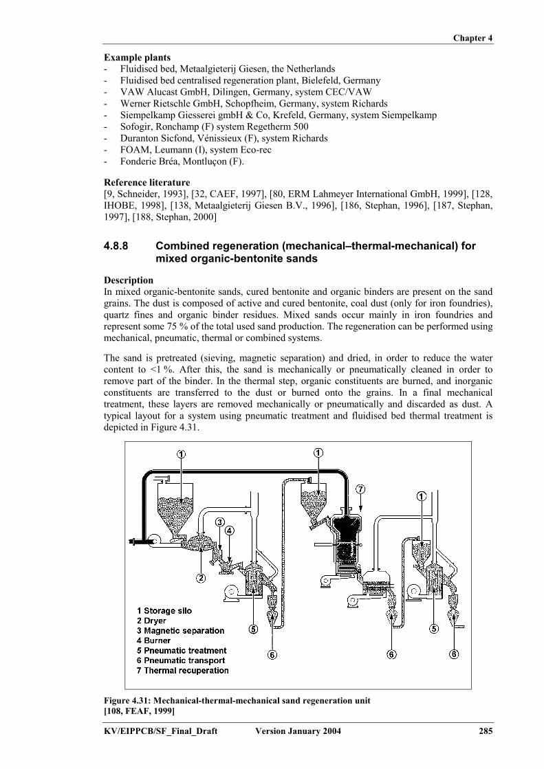
Chapter 4
KV/EIPPCB/SF_Final_Draft Version January 2004 285
Example plants- Fluidised bed, Metaalgieterij Giesen, the Netherlands- Fluidised bed centralised regeneration plant, Bielefeld, Germany- VAW Alucast GmbH, Dilingen, Germany, system CEC/VAW- Werner Rietschle GmbH, Schopfheim, Germany, system Richards- Siempelkamp Giesserei gmbH & Co, Krefeld, Germany, system Siempelkamp- Sofogir, Ronchamp (F) system Regetherm 500- Duranton Sicfond, Vénissieux (F), system Richards- FOAM, Leumann (I), system Eco-rec- Fonderie Bréa, Montluçon (F).
Reference literature[9, Schneider, 1993], [32, CAEF, 1997], [80, ERM Lahmeyer International GmbH, 1999], [128,IHOBE, 1998], [138, Metaalgieterij Giesen B.V., 1996], [186, Stephan, 1996], [187, Stephan,1997], [188, Stephan, 2000]
4.8.8 Combined regeneration (mechanical–thermal-mechanical) formixed organic-bentonite sands
DescriptionIn mixed organic-bentonite sands, cured bentonite and organic binders are present on the sandgrains. The dust is composed of active and cured bentonite, coal dust (only for iron foundries),quartz fines and organic binder residues. Mixed sands occur mainly in iron foundries andrepresent some 75 % of the total used sand production. The regeneration can be performed usingmechanical, pneumatic, thermal or combined systems.
The sand is pretreated (sieving, magnetic separation) and dried, in order to reduce the watercontent to <1 %. After this, the sand is mechanically or pneumatically cleaned in order toremove part of the binder. In the thermal step, organic constituents are burned, and inorganicconstituents are transferred to the dust or burned onto the grains. In a final mechanicaltreatment, these layers are removed mechanically or pneumatically and discarded as dust. Atypical layout for a system using pneumatic treatment and fluidised bed thermal treatment isdepicted in Figure 4.31.
Figure 4.31: Mechanical-thermal-mechanical sand regeneration unit[108, FEAF, 1999]

Chapter 4
286 Version January 2004 KV/EIPPCB/SF_Final_Draft
Achieved environmental benefitsReduction of the amount of sand for disposal and of the consumption of new primary sand.
Cross-media effectsThe regeneration of sand requires additional energy and causes additional dust emissions andresidual dust for disposal.The general evaluation of internal regeneration versus external re-use, and the correspondingcross-media effects, are discussed separately below.
Operational dataOperational data for a mechanical-thermal-mechanical treatment are given in Table 4.65.
Parameter Units FoundryN
FoundryO
FoundryP
Sand flow (tonne/h) 1 2 3
Maximum humidity of the sand input (%) 1 1 1
Total installed electric power (kW) 150 215 400Natural gas (Nm3/h) 31 62 155Thermal treatment- average airflow(fluidisation + combustion)
(Nm3/h) 700 1200 3000
Treatment temperature (ºC) 800 800 800
Average treatment time (min) 20 20 20
Flue-gas flow (Nm3/h) 200 300 500
Cooling- type- water flow in the circuit (m3/h)
Fluidised bed with watercirculation
15 30 75
Sand temperature at exit (ºC) 30 – 40
Total energy consumption:- electric- gas
100260
90260
70260
Compressed airflow (Nm3/h) 150 210 330
Efficiency of the installation 70 – 80 %
Regenerate sand quality:- granulometry- loss on ignition
Unchanged�0.1 %
Re-use of the regenerated sand:- mould making- core-making
100 %70 – 80 %
Table 4.65: Operational data of a mechanical-thermal-mechanical treatment system (pneumatic -fluid bed - pneumatic)[108, FEAF, 1999]
German data for a 85000 tonne/yr (13 – 15 tonne/h) installation provide the following off-gascomposition:
- SO2: 118 mg/Nm³- NOx: 150 mg/Nm³- total C: 10 mg/Nm³- CO: 30 mg/Nm³

Chapter 4
KV/EIPPCB/SF_Final_Draft Version January 2004 287
ApplicabilityThis regeneration technique is used for mixed sands containing bentonite. The economical andtechnical success of the regeneration depends on the selection of the sand to be regenerated. It isnot suitable to regenerate the whole sand volume. Sand which is not thermally damaged can bere-used directly for new sand preparation. Its regeneration is not suitable, because active bindersand additives would be removed. A selection and separation has to be made during shake-out,before homogenisation. The technique cannot be applied for core sands which disrupt bentonitecharacteristics (binders of acid nature) or which change green sand characteristics (e.g. waterglass sand).
The regenerated sand can be used for core-making in the original process, for cores with low ormedium geometrical demands. The applicability for core-making is related to the initial amountof chemically-bonded sand. The applicability in other binder systems must be tested in eachcase. Furthermore, these sands may be applied without restrictions for the replacement of lossesin green sand moulding cycles. Restrictions may apply in processes that use water glass ormethyl formate bonded sands.
In recent years, various types of installations have been developed for the treatment of mixedsands, but they have not yet found broad implementation in the sector. Some only work on apilot scale. Others have been developed for a specific foundry and produce a regenerated sandsuitable for re-use only in the same process, and results cannot be transposed to other foundries.
EconomicsCosts for a 3-step installation (mechanical-thermal-mechanical) using pneumatic cleaning as themechanical step (3 tubes in 1 chamber, KGT type Jet Reclaimer) with a capacity of 2.5 tonne/hare as follows: operational costs (consumption, personnel, maintenance) - EUR 21/t, investmentcosts (8 year amortisation) - EUR 30/t, thus yielding a total regeneration cost of EUR 51/tonne.
The consumption levels are as follows:
- Electricity: 50 kWh/t- Natural gas: 18 Nm³/t (depending on the moisture content of the sand)- Compressed air: 60 Nm³/t- Wear parts: 5 EUR/t
Driving force for implementationLegislation using high disposal fees to reduce the amount of residues for disposal.
Example plantsHalberg Guss GmbH, Saarbrucken (D), thermal-mechanical system. This plant treats 13 – 15 t/hof mixed 30 % organic, 70 % inorganic bonded sand. The organic bounded sand is a 50/50mixture of Croning and cold-box sand. The regeneration yield on the basis of the amount ofused sand treated is 78 %. The regenerated sand is applied for core-making (100 % Croning;70 – 100 % cold-box).
The mechanical primary regeneration + separation of chromite (from cores) and quartz sand(both chemically-bonded) + thermal/mechanical treatment of quartz sand was demonstrated on apilot scale in Germany (1993). Separation of both sand types was needed because sintering andeutectics formation occurred in the mixed sand. The plant later closed down due to othereconomic reasons.
Reference literature[11, Schachtner and Müller-Späth, 1993], [37, Winterhalter, et al., 1992], [108, FEAF, 1999],[122, Kirst, 1999], [128, IHOBE, 1998], [153, Umweltbundesamt, 2002], [225, TWG, 2003]

Chapter 4
288 Version January 2004 KV/EIPPCB/SF_Final_Draft
4.8.9 Wet sand regeneration
DescriptionAfter metal removal, the sand is mixed with water to produce a sludge for easily separating thebinder and to allow subsequent wet screening (1.6 mm). The removal of grain-bound binderresidues is performed in the wet regeneration unit, through intensive interparticle rubbing of thesand grains. The binders are released into the wash-water. The washed sand is dried to a finalmoisture content of max. 0.3 %, dry screened (at 1.2 mm), and then cooled. This may befollowed by an additional magnetic iron extraction and a final dust collection. The binderresidue is separated from the suspension and treated to allow its safe, disposal.
The main advantage of the process over mechanical and thermal processes is that it allows realtime process monitoring. Through pH control, continuous follow-up of the process is possible,allowing corrective real-time action if needed and producing a continuous quality regeneratedsand. The technique allows removal of the binder layer through wet mechanical action,combined with chemical action when needed, without wearing the sand grains.The process mainly aims to lower both the oolitisation degree of used sand (LOI max. 1 %) andthe acid content.
Achieved environmental benefitsReduction of the amount of sand for disposal and of the consumption of new primary sand.
Cross-media effectsThe wet process generates a sludge for disposal and a waste water stream. A serious problem ofthis waste water flow is the bad sedimentation of bentonite, and its difficult removal out ofwaste water. Waste water from water glass sands regeneration shows the presence of alkalineions. These ions are difficult to separate from the waste water.
ApplicabilityThe wet regeneration system can only be applied to green sand and silicate- or CO2-bondedsands. Regeneration from these types of processes allows full re-use of the regenerated sand inboth moulds and cores. Tests on regenerated green sand showed the possibility of producinggood quality cold-box cores with an acceptable binder quantity (1.8 % in total).
EconomicsWithin the Italian foundry market, a centralised wet regeneration plant can offer regeneratedsand at a price lower than that of new sand.
Driving force for implementationThis system is reported to be able to cope with changes in used sand quality better thanmechanical or thermal processes. This makes it suitable when considering a centralised sandregeneration plant.
Example plantsSafond centralised green sand wet reclamation plant, which since 1981 has been treating230000 tonnes/yr of used sand.
One Polish foundry (Odlewnia Zeliwa Srem s.a., Srem (PL)) operates a wet regeneration offuran bonded sand. The operation is governed by site-specific factors and the technique cannotbe considered for transposing to other sites.
Reference literature[37, Winterhalter, et al., 1992], [140, EU Thematic Network Foundry Wastes, 2001], [225,TWG, 2003]

Chapter 4
KV/EIPPCB/SF_Final_Draft Version January 2004 289
4.8.10 Regeneration of water glass sand using pneumatic systems
DescriptionWater glass sand has been traditionally difficult to regenerate. The use of a pneumatic systemhas allowed the setting up of regeneration plants operating of a 60 % regeneration ratio. Thesystem works along the same principle as mentioned above (see Section 4.8.6). For this type ofbinder however, the sand needs to be heated to 220 ºC before the regeneration, in order to makethe silicate layer brittle. The sand should have a humidity below 0.3 % before regeneration. Theregenerated sand may be re-used in the same system. In order for the ester to work properly, theregenerated sand must be cooled to below 20 ºC, before feeding back into the moulding cycle.Water glass sand regeneration systems comprise the following process steps: breaking –drying/heating – (pneumatical) reclamation – cooling - filtration.
This technique has a lower performance than the thermal regeneration of organically boundsands. The following limitations occur:- lower immediate compressive strength- shorter applicability times of the core sand mixtures- stability loss upon storage of cores- loss of retained compressive strength, especially with the use of binders with high
collapsibility.
In order to compensate for these problems, changes to the processing scheme or the bindermixes are needed.
Achieved environmental benefitsThe application of water glass sand as a binder has a low environmental impact, compared tothe application of organic binders. This technique allows the (partial) regeneration of the waterglass bonded sand and thus reduces the need for used sand disposal and primary raw materialuse.
Cross-media effectsIn order to heat up the sand, natural gas is combusted. The corresponding CO2-emission isestimated to be 18 kg/tonne of used sand. NOx emissions will also occur.
Operational dataA German example plant operates a pneumatical unit in a step-wise cycle. The sand is first driedby the introduction of heated air (5 min/220 ºC). After this, the pneumatic cleaning is started byinjecting of shots of compressed air (70 min.). This is followed by a final dedusting phase,during which only fluidising air is introduced (2 min). There is no need for further cooling,since the sand cools down to a workable temperature.
The yield of regenerated sand for one cycle operation is reported to be 85 % of the initial weight(on the basis of SiO2). In order to produce stable cores, and taking into account the furtherreduction of sand quality upon a second regeneration cycle, a maximum regeneration ratio of62 % may be achieved (leaving 38 % new sand addition).
Specific consumption levels are as follows (for a 1500 tonne/yr; 0.5 tonne/h unit):- natural gas consumption: 104.4 kWh/t used sand- electricity consumption: 74.5 kWh/t used sand.
A Polish example plant (in a cast steel foundry) consists of the followig units: vibratory crusher– drier – impact plate regenerator – cascade dedustor – electromagnetic separator. The technicaldetails of the installation are given in Table 4.66. The regenerated sand is re-used in thepreparation of silicate-bonded moulding-sand. The silicate-sand is used as backing sand inmould making, with alkaline sand used as contact sand. The total sand balance (on a yearlybasis) shows a use of 45 - 47 % regenerated sand.

Chapter 4
290 Version January 2004 KV/EIPPCB/SF_Final_Draft
Characteristic ValueCapacity 10 tonne/hRecovery ratio 90 %Content of regenerated sand in the moulding-sand 50 – 60 %Working power 76 kWDe-dusting system efficiency (2 bag filters) 99.4 %Installation area for regeneration site 220 m²
Table 4.66: Operational data of a silicate sand regeneration unit[200, Metalodlew s.a., 2002]
A Spanish example plant (cast steel foundry) reported a re-use of 80 - 88 % (with a yearlyaverage figure of 12.5 % new sand addition) of regenerated silicate-ester sand in a manualmoulding line, used for the casting of big pieces. The regeneration system consists of: vibratorycrusher – heating in an indirectly heated reactor (‘quemador’ with gas burner in a side chamber)– cooling in a water-cooled heat-exchange tower – impact cleaning in a rotary mixing chamber.
Italian example plants also use special equipment for heating sand to temperatures of 140 ºC to150 ºC, to enable the removal of defects and the embritlement of the water glass coating. This isfollowed by mechanical treatment in a rotary wiper, dedusting and finally cooling. Aschematical drawing of the rotary regeneration unit is given in Figure 4.32.
Figure 4.32: Rotary mechanical regeneration unit[225, TWG, 2003]
The equipment has an energy consumption of 35 kW/tonne of regenerated sand. The operationalloss of sand is about 5 %. For moulding and core making mixtures, over 90 % of regeneratedsand can be used. The achievable regeneration ratio depends on the intensity and time ofregeneration and the operational sand loss. Sand losses occur during each part of the wholecycle of mixing, preparation, transportation, mould production and regeneration.
ApplicabilityThe applicability of regeneration for water glass sands depends on the catalyst used. Withclassic polyacetate glycerol esters, regeneration is no longer possible after a number of cycles.With carbonaceous esters, regeneration is possible and even easier than for silicate-CO2 sand. Ifthe sand cannot be cooled below 20 ºC before returning to the mixer, esters with a slow reactionneed to be used. These cannot be regenerated. This situation may occur during summer in hotclimates.
The re-use of the regenerated water glass sand for the preparation of organically bound mouldsor cores is problematic. The elevated content of electrolytes (binders) prohibits their use in other

Chapter 4
KV/EIPPCB/SF_Final_Draft Version January 2004 291
core binder systems. The highly basic water glass residues have a negative effect on bondingand core stability, in both neutral as well as alkaline binder systems. Applications in green sandcycles and acidic core binder systems have not yet been successfully implemented. This may bedue to a reduced interest in the development of this application.
Because of the low quality of secondary regenerated sand, it is necessary during de-coring andsand collection to identify the amount of regenerated sand and its origin (e.g. number of cycles),and to then discard any unusable sand.
Due to the high costs and relatively low regeneration ratio, depreciation of the installation in areasonable time can only be guaranteed for plants with a capacity >2500 tonnes/yr.
EconomicsThe processing cost of this technique for the German example plant is around EUR 60/tonne.This high cost was the reason one operator closed his plant down and went back to the disposalof the water glass sand, which he could do for the lower cost of EUR 30/tonne.The reported operational cost by the Spanish example plant is EUR 10/tonne.
Driving force for implementationTo enable the regeneration of water glass sand, which has a good environmental performance incertain applications.
Example plants- KGT Jet Reclaimer centralised regeneration plant for 4 foundries, constructed 1998 at Fa.
Bröer, Schwetzingen (D) but stopped operation in 2001- Metalodlew s.a., Krakow (PL)- Lur Sue s.l., Lora Del Rio (E)- Fonderia Arno Metallurgia, S. Vittore Olona (I)- Faser Spa, Rogeno (I)- Talleres De Amurrio S.A. Amurrio (E)- Daros Piston Rings AB, Partilla (S).
Reference literature[128, IHOBE, 1998], [152, Notzon and Heil, 1998], [154, Baum, 2002], [200, Metalodlew s.a.,2002], [210, Martínez de Morentin Ronda, 2002], [225, TWG, 2003], [228, Galante, et al.,1997]
4.8.11 Internal re-use of uncured core sand
DescriptionCore production generates sand residues in the form of broken cores, cores with small mistakesand excess sand from the core-making machines. The excess sand can be hardened in a specificunit. Subsequently the various unused core sand flows are fed to a breaking unit. The resultingsand may be mixed with new sand for the production of new cores.
Achieved environmental benefitsInternal re-circulation of 5 - 10 % of the core sand, which otherwise would be disposed of.
Cross-media effectsNo cross-media effects occur.
ApplicabilityThis technique applies for polyurethane (cold-box) and furan resin-bonded sands. Other bindersdo not allow this technique.

Chapter 4
292 Version January 2004 KV/EIPPCB/SF_Final_Draft
The implementation of the technique necessitates changes in the process control. The optimumratio of re-circulated and new sand will need to be determined. Additionally changes in binderaddition or composition may be needed.
EconomicsThe technique requires an investment cost of EUR 250000 – 500000 for the combined treatmentand breaking unit. Operational costs are about EUR 12/t. These costs are balanced by areduction in disposal costs and purchasing costs for new sand.The technique is only viable for core intensive production.
Driving force for implementationOptimisation of the use of primary materials and reduction of the amount of waste for disposal.
Example plantsThe technique was reported by several large-scale foundries.
Reference literature[82, IfG - Institut für Gießereitechnik, 1996], [110, Vito, 2001]
4.8.12 Re-use of dusts from the green sand circuit in mould making
DescriptionDust is collected through the exhaust filtration from the shake-out installation and from thedosing and handling stations for dry green sand. The collected dust contains active bindercompounds and may be recycled into the green sand circuit.
Achieved environmental benefitsReduction in the use of binders (bentonite), and additives (carbon), through internal re-circulation.
Cross-media effectsNo cross-media effects exist.
Operational dataAn iron automotive foundry, using an automated moulding line with a production of 8000 t/yrcastings produces 480 t/yr of dust. This sand is collected, cooled and recycled into the sandmixer. The collected dust contains 23 % active bentonite and 10 % carbon. 50 % of the dust canbe re-circulated without any risk of loss of quality due to fine dust.
ApplicabilityThe technique may be applied in new and existing green sand installations.
EconomicsThe technique requires an investment of EUR 25000 for storage and transport equipment. Theamortisation period is 8 years, with a discount rate of 8 %, for a 240 tonne/yr installation,resulting in a capital cost of EUR 17/tonne of treated sand. There are no additional operationalcosts since the operation of the overall installation does not change.
Driving force for implementationTo optimise the use of primary materials and to reduce the amount of waste for disposal.
Example plantsIron automotive foundry in Germany.
Reference literature[82, IfG - Institut für Gießereitechnik, 1996]

Chapter 4
KV/EIPPCB/SF_Final_Draft Version January 2004 293
4.8.13 External re-use of used sand and the undersize from the sandcircuit and regeneration processes
DescriptionUsed sand and undersize sand from the sand circuit or sand regeneration may find some externalapplications, with the main areas of application being:- the construction industry (road construction, highway construction)- the building materials industry (cement, bricks, limestone manufacture)- in the filling of mining cavities- in landfill construction (roads on landfills, permanent covers).
The limits of these applications are given by either technical criteria for construction materialsand/or environmental criteria for the given application. Environmental criteria are generallybased on leaching properties and the content of organic compounds. These differ betweenvarious European regions. Used sands generally show a low metal leaching potential. Anexceedence of the limit values may occur for materials with a high content of organic binder orwith specific additives, such as lustrous carbon.
Due to its high quartz content and appropriate granulometry, used sand may be applied as avirgin sand substitute in road construction. Application in the production of building materials(concrete, bricks, tiles, glass wool, …) are technically feasible but require a higher level ofcomposition control and logistics. Industrial scale trials have been successfully applied in:- road bases- filling material- drainage material- concrete elements- cement production (depending on the silicon need of the process. In Germany this
application is of major importance)- filling of mining cavities (due to its good supporting capacities. Used sand is used in this
application in Germany)- final cover on landfills (mixed with water glass and other wastes, examples in the
Netherlands)- construction material for the reinforcement of dikes- vitrification of hazardous waste.
A survey table which gives more detailed information for the different sand types is given inSection 4.9.
Other fields of application are the fabrication of bricks, secondary copper smelting and zincrecuperation.
It should be stressed that discussions on the (type of) external utilisation fall beyond the scopeof the current reference document. However, in general, it can be stated that the sand usuallyneeds no pretreatment and is transported from the foundry after collection and intermediatestorage. Usually in order to guarantee a continuous quality of the material, a separate collectionand storage system will be developed. Furthermore, the quality of the material needs to becontrolled through regular analyses.
Achieved environmental benefitsIn external applications, the used sand substitutes, and therefore saves, virgin materials. Ingeneral, the external application does not require any treatment of the sand and therefore doesnot generate any energy expense for the foundry.
Cross-media effectsResidues of organic coatings are possible sources of aromatic hydrocarbons.

Chapter 4
294 Version January 2004 KV/EIPPCB/SF_Final_Draft
ApplicabilityThis technique is applicable for new and existing installations, as long as they can find a buyerfor the waste sand.
The use of surplus foundry sand does not reduce the wear resistance of asphalt concrete. Theuse of surplus foundry sand together with the dust from the same foundry process is possible inPortland cement concrete production. The use of surplus foundry sand together with fly ash andsteel slag is possible in mineral wool production. The use of surplus foundry sand in thecomposting process of biowastes does not negatively affect the environmental or technicalfeatures of the final product, i.e. the topsoil. The use of surplus green sand in mineral liners istechnically and environmentally possible in the top layers of the landfill.
EconomicsCosts for external utilisation depend on the local market and the transport and storage costsneeded.
Investment costs for separate collection and storage are minimal. Often these can be realisedthrough organisational measures. Operational costs for analyses and administration may be upto EUR 5000/yr. On the benefit side, there is a reduction in the costs for disposal (up toEUR 125/tonne).
Driving force for implementationLegislation using high disposal fees to reduce the amount of residues for disposal.
Example plantsMultiple examples have been reported throughout Europe, e.g. by Finland, the Netherlands,Belgium, Germany, UK.
Reference literature[82, IfG - Institut für Gießereitechnik, 1996], [110, Vito, 2001], [128, IHOBE, 1998], [169,Orkas, 2001], [171, The Castings Development Centre, 1999]
4.9 Dust and solid residues: treatment and re-use
4.9.1 Introduction
A good segregation of materials is essential to facilitate opportunities for recovery, recyclingand re-use. Waste should always be recycled or recovered unless a satisfactory justification hasbeen accepted by the regulator that recovery is “technically and economically impossible”.
In general, the waste streams comprise:- raw material dusts collected in bag or cartridge filters- slag from desulphurisation- slag/dross from melting- melting dust and fume collected in a filter plant- casting dust and fume collected in a filter plant- fettling dusts collected in an abatement plant- chips and turnings from fettling- used abrasives from shot blasting- scrubber liquors and sludges and output from the effluent treatment plant- refractory waste from launders and ladles- sand- chemical and oil containers- general inert industrial waste.

Chapter 4
KV/EIPPCB/SF_Final_Draft Version January 2004 295
Waste should be recovered wherever practicable. Other than sand, the most significant wastesare:- slag from the melting and metal treatment processes- dust collected from abatement plants- collected sludge- refractory waste.[160, UK Environment Agency, 2002]
4.9.2 (Pretreatment for) external re-use of solid residues
DescriptionIn order to allow an external re-use of solid residues, the material may need treatment. Table4.67 gives the required processing for the various (non-sand) solid residues and possiblelimitations for their re-use.
For cupola furnace slag, the physical form, and therefore to some extent its options for re-use,depend on the type of de-slagging used. Dry slagging, i.e. pouring of the slag in pots for coolingand solidification, produces a crystalline non-porous mineral. Concerning technological aspects,this slag is comparable to blast furnace slag. Wet slagging generates a granular slag by coolingthe slag with a water jet.
Residue type Treatment LimitationsAir-cooled cupola slag Crushing - generation of glassy dust
- handling requirements due to glassynature
Water quenched cupola slag None - generation of glassy dust- handling requirements due to glassy
natureInduction melting slag Crushing - generation of glassy dust
- handling requirements due to glassynature
- little data available on leachatesEAF slag Crushing - generation of glassy dust
- handling requirements due to glassynature
- little data available on leachatesDesulphurisation slag Extraction of metal and
other coarse particles- handling requirements, CaC2 needs
careful handling to avoid injury- run-off- may be a special waste
Dusts and sludges Sludge pressing, dryingand granulation needed formost applications
- health and safety requirements for somedusts
- problems with transport of dustymaterials
- high leaching potential due to nature ofproduct and large surface area
Table 4.67: Necessary treatment and possible limitations for external re-use of solid residues[171, The Castings Development Centre, 1999]
Achieved environmental benefitsIn external applications, the re-used material will serve as a secondary construction material andcan substitute for virgin materials. The recycling results in a reduction in the amount of materialfor disposal.
Cross-media effectsPretreatment requires energy and may generate dust emissions.

Chapter 4
296 Version January 2004 KV/EIPPCB/SF_Final_Draft
ApplicabilityThe technique is applicable for new and existing installations, as long as there is a suitable alocal market for the residue.
A survey of external re-use applications for various solid wastes is given in Table 4.68.
SAND SLAGS OTHERSUMMARY OF RE-USE
APPLICATIONS
Construction type uses
Gre
ensa
nd
Alk
aline
phen
olic
Phen
olic
ureth
ane
Fura
n
Resin
shell
Sodi
um si
licate
Air-
cool
ed cu
pola
Wate
r qu
ench
edcu
pola
Indu
ction
Elec
tric a
rcfu
rnac
e
Des
ulph
urisa
tion
Inve
stmen
t cas
ting
shell
Dus
ts an
d slu
dges
Asphalt x x + + + O xBallast + +Block making + x + + x + xBrick manufacture x x + + + + +Cement x x + x xCoarse aggregate substitute x x x xConcrete x + + +Fine aggregate substitute x x + + + +Foamed concrete, etc. x x +Insulating/mineral/glasswools + + + + + + + + +
Lightweight aggregateproduction +
Mortar production +Road base construction x + + x x x x xRoofing felt x
Re-use in another foundryAs new sand addition togreensand x
Soil type usesArtificial topsoils x + + x + +Decorative ground cover + +Ground cover in ridingstables +
Fertiliser filler xLandfill - capping x x + +Landfill - daily cover x x + x x xLandfill - liner + +Soil modifier/improver + + + + + + + + +
MiscellaneousAbrasives/blasting media x + x +Absorbent media +Blast furnace slag cementmanufacture + +
Chemical/industrialapplications x
Slaked lime replacement + +Smelting fluxes + + + +Waste vitrification + + + + +x Proven re-use application, with successful projects running in the UK+ Re-use application that has been proven in theory but no re-use project is currently running in the UKO Unsuitable for re-use in untreated from
Table 4.68: Summary of external re-use applications for solid foundry residues (status 1999)[171, The Castings Development Centre, 1999], [202, TWG, 2002]

Chapter 4
KV/EIPPCB/SF_Final_Draft Version January 2004 297
EconomicsThe costs associated with re-use are mainly the processing and transport costs, but these canpossibly be reduced by taking into account the income generated from selling the material.However, the latter in general may be low or close to zero, whereas typically mechanicaltreatment costs are in the range of EUR 8/tonne.
The further the materials have to be transported, the greater the increase in costs. In order toassess the economic viability of the re-use option, the applicable disposal costs should be takeninto account. These differ between various regions and depend on the residue type.
Driving force for implementationLegislation stimulating the recycling of mineral wastes, partly by setting high disposal fees toreduce the amount of residues for disposal.
Example plantsMultiple examples of sand and slag re-use have been reported throughout Europe, e.g. inFinland, the Netherlands, Belgium, Germany, UK
Reference literature[171, The Castings Development Centre, 1999]
4.9.3 Minimisation of slag forming
DescriptionThe production of slag can be minimised using in-process measures, such as:- using clean scrap- using a lower metal temperature- preventing overshoots (temporary high temperatures)- preventing long standing times of molten metal in the melting furnace- making adequate use of fluxes- making adequate use/choice of refractory lining- applying water cooling of the furnace wall to avoid usage of refractory lining.
Achieved environmental benefitsMinimisation of residue production and reduction of emissions to air.
Cross-media effectsNo cross-media effects occur from these minimisation measures. Concerning the melting ofclean scrap, the considerations raised in Section 4.1.4 should be taken into account.
ApplicabilityThis technique applies to all new and existing installations. The applicability of the use of cleanscrap has been fully discussed in Section 4.1.4.
EconomicsThis technique does not involve any investement, since it concerns operational measures.
Driving force for implementationHigh disposal costs for residues.
Example plantsThis technique is part of existing operational procedures in the majority of European foundries.
Reference literature[103, Vereniging van Nederlandse Gemeenten, 1998]

Chapter 4
298 Version January 2004 KV/EIPPCB/SF_Final_Draft
4.9.4 Cupola furnace
4.9.4.1 Collection and recycling of coke breeze
DescriptionThe handling, transport and charging of coke results in the production of coke breeze. Specificmeasures may be adopted for the collection and recycling of this material e.g. collection systemsbelow conveyor belts or, at charging points.
The collected material may be recycled into the process by injection into the cupola or in itsutilisation for recarburisation.
Achieved environmental benefitsMinimisation of the production of residues.
Cross-media effectsNo cross-media effects apply.
ApplicabilityThis technique applies to new and existing installations.
Driving force for implementationHigh disposal fees for solid residues.
Example plantsThe technique is reported for several foundries in Europe.
4.9.4.2 Recirculation of filter dust into cupola furnace
DescriptionCupola filter dust is re-injected into the cupola furnace. The aim of this technique is to achievean accumulation of zinc in the dust, up to a level that allows reprocessing with Zn recovery(>18 %). Zn recovery is performed using the Waelz process.
Recirculation of the dust can be done through re-injection at the tuyères or by charging dustpellets through the charging door. Both techniques are applied on an industrial scale. A massbalance analysis can be used to show that the zinc is sublimated and reappears in therecuperated dust. After a number of cycles the dust is rich enough in Zn to allow recovery.Recovery is technically possible above an 18 % Zn level.
There are two limits to recycling dust:- the zinc essentially appears in the form of Zn2SO4, a compound containing 64 % Zn. This
therefore sets the maximum level of enrichment- the dust is also enriched in alkali, which causes flame extinction in the combustion
chamber. This effect may be solved by injecting water vapour into the combustion air.
Injection at the tuyères can be based on several principles. There are fifteen (status May 2001)European foundries recycling dust by injection at the tuyères. Eleven use the positive pressuretechnique, and four use the venturi suction technique. The advantage of the venturi technique isthat it consumes less injection air and so cools the melting zone less. With both techniques, thedust becomes sticky after successive cycles. In the case of the venturi technique, the dust musttherefore be mixed with petcoke to allow its transport in the pipes.
The recirculation of dust through agglomeration and charging is much less common than tuyèreinjection. This is because the process is much more difficult to automate. Furthermore, goodcontrol and knowledge of the pelletisation process is needed to give the pellets the necessary
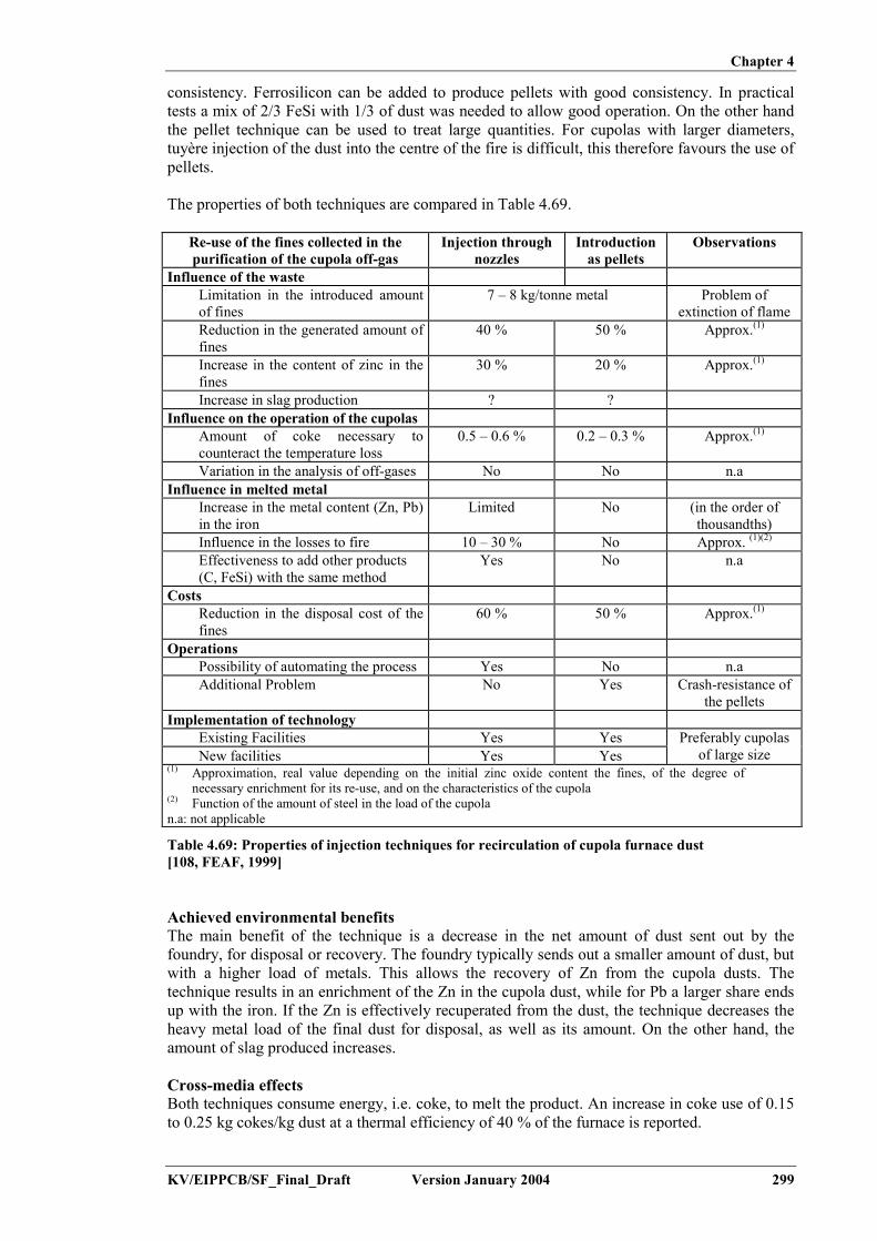
Chapter 4
KV/EIPPCB/SF_Final_Draft Version January 2004 299
consistency. Ferrosilicon can be added to produce pellets with good consistency. In practicaltests a mix of 2/3 FeSi with 1/3 of dust was needed to allow good operation. On the other handthe pellet technique can be used to treat large quantities. For cupolas with larger diameters,tuyère injection of the dust into the centre of the fire is difficult, this therefore favours the use ofpellets.
The properties of both techniques are compared in Table 4.69.
Re-use of the fines collected in thepurification of the cupola off-gas
Injection throughnozzles
Introductionas pellets
Observations
Influence of the wasteLimitation in the introduced amountof fines
7 – 8 kg/tonne metal Problem ofextinction of flame
Reduction in the generated amount offines
40 % 50 % Approx.(1)
Increase in the content of zinc in thefines
30 % 20 % Approx.(1)
Increase in slag production ? ?Influence on the operation of the cupolas
Amount of coke necessary tocounteract the temperature loss
0.5 – 0.6 % 0.2 – 0.3 % Approx.(1)
Variation in the analysis of off-gases No No n.aInfluence in melted metal
Increase in the metal content (Zn, Pb)in the iron
Limited No (in the order ofthousandths)
Influence in the losses to fire 10 – 30 % No Approx. (1)(2)
Effectiveness to add other products(C, FeSi) with the same method
Yes No n.a
CostsReduction in the disposal cost of thefines
60 % 50 % Approx.(1)
OperationsPossibility of automating the process Yes No n.aAdditional Problem No Yes Crash-resistance of
the pelletsImplementation of technology
Existing Facilities Yes YesNew facilities Yes Yes
Preferably cupolasof large size
(1) Approximation, real value depending on the initial zinc oxide content the fines, of the degree ofnecessary enrichment for its re-use, and on the characteristics of the cupola
(2) Function of the amount of steel in the load of the cupolan.a: not applicable
Table 4.69: Properties of injection techniques for recirculation of cupola furnace dust[108, FEAF, 1999]
Achieved environmental benefitsThe main benefit of the technique is a decrease in the net amount of dust sent out by thefoundry, for disposal or recovery. The foundry typically sends out a smaller amount of dust, butwith a higher load of metals. This allows the recovery of Zn from the cupola dusts. Thetechnique results in an enrichment of the Zn in the cupola dust, while for Pb a larger share endsup with the iron. If the Zn is effectively recuperated from the dust, the technique decreases theheavy metal load of the final dust for disposal, as well as its amount. On the other hand, theamount of slag produced increases.
Cross-media effectsBoth techniques consume energy, i.e. coke, to melt the product. An increase in coke use of 0.15to 0.25 kg cokes/kg dust at a thermal efficiency of 40 % of the furnace is reported.

Chapter 4
300 Version January 2004 KV/EIPPCB/SF_Final_Draft
In addition, the injection of cold dust in the hot melting zone will lower the flame temperature,which accordingly will have to be restored by an injection of oxygen. The total amount of slagproduced will also increase.
The loading of sticky dust to several of the internal parts of the system will cause medium-termloss of efficiency and possibly operational problems. These have not been quantified.
Operational dataAn analysis of the input and output flows of French cupolas resulted in the mass balance shownin Figure 4.33 and Figure 4.34. The contribution of each flow to the Zn-in/output is giventogether with the zinc-level (as mass and %). The percentages given are average values over theindicated measuring period.
Figure 4.33: Zinc distribution for tuyère injection, upon injection during 20 days[156, Godinot, 2001]
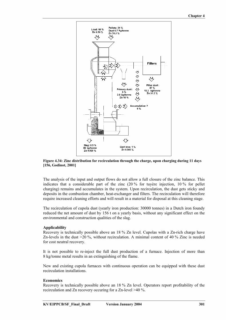
Chapter 4
KV/EIPPCB/SF_Final_Draft Version January 2004 301
Figure 4.34: Zinc distribution for recirculation through the charge, upon charging during 11 days[156, Godinot, 2001]
The analysis of the input and output flows do not allow a full closure of the zinc balance. Thisindicates that a considerable part of the zinc (20 % for tuyère injection, 10 % for pelletcharging) remains and accumulates in the system. Upon recirculation, the dust gets sticky anddeposits in the combustion chamber, heat-exchanger and filters. The recirculation will thereforerequire increased cleaning efforts and will result in a material for disposal at this cleaning stage.
The recirculation of cupola dust (yearly iron production: 30000 tonnes) in a Dutch iron foundyreduced the net amount of dust by 156 t on a yearly basis, without any significant effect on theenvironmental and construction qualities of the slag.
ApplicabilityRecovery is technically possible above an 18 % Zn level. Cupolas with a Zn-rich charge haveZn-levels in the dust >20 %, without recirculation. A minimal content of 40 % Zinc is neededfor cost neutral recovery.
It is not possible to re-inject the full dust production of a furnace. Injection of more than8 kg/tonne metal results in an extinguishing of the flame.
New and existing cupola furnaces with continuous operation can be equipped with these dustrecirculation installations.
EconomicsRecovery is technically possible above an 18 % Zn level. Operators report profitability of therecirculation and Zn recovery occuring for a Zn-level >40 %.

Chapter 4
302 Version January 2004 KV/EIPPCB/SF_Final_Draft
From the practical data from two foundries in France, additional operational costs werecalculated. Tuyère injection showed an additional operational cost of EUR 0.35/tonne cast iron;pellet injection EUR 0.90/tonne cast iron. This calculation does not take into account any extracosts for slag disposal or maintenance works.
In the case of Venturi injection, the following data apply. In a German reference plant over a5 year period an average of 7.5 kg zinc dust/tonne melted iron could be delivered to theprocessing industry. Disposal costs were thereby reduced by EUR 1.97/tonne liquid iron.Furthermore, 20 % of the cokes could be replaced by petcokes. This allowed a reduction in thefuel cost of 15 %, which corresponded to a cost reduction of EUR 2.56/tonne liquid iron. Thiscalculation does not take into account any extra costs for slag disposal or maintenance works.
Driving force for implementationHigh disposal costs for furnace dusts.
Example plantsVenturi (NPT):
Pont-a-Mousson, Brebach (F)Positive Pressure (VELCO):
John Deere, Mannheim (D)
Reference literature[108, FEAF, 1999], [110, Vito, 2001], [140, EU Thematic Network Foundry Wastes, 2001],[156, Godinot, 2001], [181, Ruffin and Godinot, 1998], [198, Georg Fischer, ], [202, TWG,2002]
4.9.5 EAF
4.9.5.1 Recycling of filter dust and sludge (from EAF melting)
DescriptionDry collected furnace dust can, under certain circumstances, be recycled in the furnace. Thedust will preferably be pretreated, e.g. by pelletising or briquetting, as this will reduce theamount of dust that is just blown through the furnace. The idea is to recover the metallic part ofthe dust and to melt the inorganic part to slag. In general, the dust is added at the beginning ofeach melting cycle.
As discussed for cupola furnaces, and for the EAF, in some cases where significant quantities ofZn containing scrap are used, recycling can lead to a Zn enrichment of the furnace dust up to alevel where it can be used in the zinc industry for the recovery of Zn if economically viable (upto 30 - 40 %).
Achieved environmental benefitsThe main benefit of the technique is a decrease in the net amount of dust sent out by thefoundry, for disposal or recovery. The produced dust contains a higher load of metals. Thisallows the recovery of Zn from the EAF dusts. The technique results in an enrichment of the Znin the cupola dust, while for Pb a larger share ends up in the iron. If the Zn is effectivelyrecuperated from the dust, the technique decreases the heavy metal load of the final dust fordisposal, as well as its amount. On the other hand, the amount of slag produced, increases.
Cross-media effectsDust recycling possibly reduces furnace efficiency and rises the consumption of electricalenergy (approx. 20 - 30 kWh/tonne). The technique results in an increased production of slag.
Operational dataOperational data from EAF steelmaking show a plant which recycles 75 % EAF dust from anoriginal yield of 20 – 22 kg/t, and so only has to take care of about 50 % of the dust, with anaverage zinc content of 35 %.

Chapter 4
KV/EIPPCB/SF_Final_Draft Version January 2004 303
ApplicabilityThe technique generally applies for dusts with a high metallic load. The actual applicabilitythough depends on many factors, that may be dissimilar for different plants.
EconomicsThe technique does not involve any additional investment.
Driving force for implementationHigh disposal costs for furnace dusts.
Example plantsThis technique is performed in several European foundries.
Reference literature[32, CAEF, 1997], [211, European IPPC Bureau, 2000]
4.9.5.2 Recycling of Al slags and residues
DescriptionThe possibilities of recycling depend on the product and the generated wastes. Swarfs aremostly recovered for internal remelting while other scrap (containing too much other metal) willusually be sold to secondary aluminium production.
Achieved environmental benefitsMinimisation of the production of residues.
Cross-media effectsNo cross-media effects apply.
ApplicabilityThis technique applies to new and existing installations.
Driving force for implementationHigh disposal fees for solid residues.
Example plantsThe technique is commonly applied in aluminium foundries.
Reference literature[225, TWG, 2003]
4.10 Noise reduction
DescriptionThe foundry process contains various point sources of noise. These include:- scrap handling- furnace charging- burners- HPDC automates- shake-out- grit-blasting- core (and mould) shooting- finishing- all motors and hydraulic systems- transport (tipping, loading, etc.).

Chapter 4
304 Version January 2004 KV/EIPPCB/SF_Final_Draft
The overall reduction of noise levels involves developing a noise reduction plan. Here each ofthe sources needs to be checked and evaluated. Alternative techniques with lower noise levelsmay be applied and/or point sources may be enclosed. Examples for alternative techniques havebeen given in Section 4.2.4.2 (oxyburner in RF) and 4.2.2.2 (foamy slag for EAF). Someexamples of the enclosure of sources have been given for furnaces (Section 4.5.3.1) and shake-out (4.5.9.3).
General measures include:- using noise reducing flaps on all outside doors and closing all doors (and keeping them shut
as much as possible), especially during the night- actively blowing air into the foundry hall. This causes a small increase in the indoor
pressure and keeps the noise inside- enclosing fans, insulating of ventilation pipes and using of dampers- minimising the number of transport activities during the night.
Full enclosure of the foundry building may be considered as well. This will also require setting-up a climate control system, to limit the temperature inside the building.
Achieved environmental benefitsReduction of noise pollution.
Cross-media effectsEnclosing (parts of) the foundry building may necessitate the installation of a climate controlsystem, the operation of which requires energy.
Operational dataA Belgian aluminium foundry is currently developing a noise reduction plan. The aim is for thegeneral noise level to be reduced from 50 dBA to 40 dBA. This involves the study of 170sources. Specific measures are taken to reduce the overall noise level between 22.00 h and6.00 h. Additionally air is blown into the foundry hall, creating a small pressure difference tokeep the noise inside. The total inside air volume is refreshed 36 times each hour.
Another Belgian foundry is running a project to reduce noise emissions by fully closing thefoundry building. This requires the setting-up of a climate control system, in order to achieve amaximum inside-outside temperature difference of 8 ºC. The system is currently going throughsubsequent revisions, so tests are still ongoing.
ApplicabilityThis technique applies to all new and existing installations. The level to which measures shouldbe taken depends on the foundry location.
Driving force for implementationRegulation on noise levels from industrial installations.
Example plants- MGG, Hoboken (B): noise reduction plan- Hayes-Lemmertz, Hoboken (B): total building enclosure.
Reference literature[225, TWG, 2003]
Chapter 4
KV/EIPPCB/SF_Final_Draft Version January 2004 305
4.11 Decommissioning
DescriptionSome techniques to consider are:- considering later de-commissioning at the design stage, thereby minimising risks and
excessive costs during later de-commissioning- for existing installations, where potential problems have been identified, putting in place a
programme of improvements. These improvements designs need to ensure that:� underground tanks and pipework are avoided where possible (unless protected by
secondary containment or a suitable monitoring programme)� there is provision for the draining and cleaning-out of vessels and pipework prior to
dismantling� lagoons and landfills are designed with a view to their eventual clean-up or surrender� insulation is used which can be readily dismantled without dust or hazards arising� any materials used are recyclable (although bearing in mind they still meet operational
or other environmental objectives)
- developing and maintaining a site closure plan, to demonstrate that, in its current state, theinstallation can be decommissioned to avoid any pollution risk and to return the site ofoperation to a satisfactory state. The plan should be kept updated as material changes occur.However, even at an early stage, the closure plan can include:� either the removal or the flushing out of pipelines and vessels where appropriate and
their complete emptying for any potentially harmful contents� plans of all underground pipes and vessels� the method and resource necessary for the clearing of lagoons� the method of ensuring that any on-site landfills can meet the equivalent of surrender
conditions� the removal of asbestos or other potentially harmful materials unless agreed that it is
reasonable to leave such liabilities to future owners� methods of dismantling buildings and other structures, for the protection of surface and
groundwater at construction and demolition-sites� testing of the soil to ascertain the degree of any pollution caused by the activities and
the need for any remediation to return the site to a satisfactory state as defined by theinitial site report
Achieved environmental benefitsPrevents environmental issues during de-commissioning.
ApplicabilityTechniques mentioned here are applicable throughout the installation’s operational lifetime,during the design and building stage of the site and activities and immediately after the siteclosure.
Reference literature[236, UK Environment Agency, 2001]
4.12 Environmental management tools
DescriptionThe best environmental performance is usually achieved by the installation of the besttechnology and its operation in the most effective and efficient manner. This is recognised bythe IPPC Directive definition of ‘techniques’ as “both the technology used and the way in whichthe installation is designed, built, maintained, operated and decommissioned”.

Chapter 4
306 Version January 2004 KV/EIPPCB/SF_Final_Draft
For IPPC installations an Environmental Management System (EMS) is a tool that operators canuse to address these design, construction, maintenance, operation and decommissioning issuesin a systematic, demonstrable way. An EMS includes the organisational structure,responsibilities, practices, procedures, processes and resources for developing, implementing,maintaining, reviewing and monitoring the environmental policy. Environmental ManagementSystems are most effective and efficient where they form an inherent part of the overallmanagement and operation of an installation.
Within the European Union, many organisations have decided on a voluntary basis toimplement environmental management systems based on EN ISO 14001:1996 or the EU Eco-management and audit scheme EMAS. EMAS includes the management system requirements ofEN ISO 14001, but places additional emphasis on legal compliance, environmental performanceand employee involvement; it also requires external verification of the management system andvalidation of a public environmental statement (in EN ISO 14001 self-declaration is analternative to external verification). There are also many organisations that have decided to putin place non-standardised EMSs.
While both standardised systems (EN ISO 14001:1996 and EMAS) and non-standardised(“customised”) systems in principle take the organisation as the entity, this document takes amore narrow approach, not including all activities of the organisation e.g. with regard to theirproducts and services, due to the fact that the regulated entity under the IPPC Directive is theinstallation (as defined in Article 2).
An environmental management system (EMS) for an IPPC installation can contain thefollowing components:
(a) definition of an environmental policy(b) planning and establishing objectives and targets(c) implementation and operation of procedures(d) checking and corrective action(e) management review(f) preparation of a regular environmental statement(g) validation by certification body or external EMS verifier(h) design considerations for end-of-life plant decommissioning(i) development of cleaner technologies(j) benchmarking.
These features are explained in somewhat greater detail below. For detailed information oncomponents (a) to (g), which are all included in EMAS, the reader is referred to the referenceliterature indicated below.
(a) Definition of an environmental policy
Top management are responsible for defining an environmental policy for an installationand ensuring that it:
– is appropriate to the nature, scale and environmental impacts of the activities– includes a commitment to pollution prevention and control– includes a commitment to comply with all relevant applicable environmental legislation
and regulations, and with other requirements to which the organisation subscribes– provides the framework for setting and reviewing environmental objectives and targets– is documented and communicated to all employees– is available to the public and all interested parties.

Chapter 4
KV/EIPPCB/SF_Final_Draft Version January 2004 307
(b) Planning, i.e.:
– procedures to identify the environmental aspects of the installation, in order todetermine those activities which have or can have significant impacts on theenvironment, and to keep this information up-to-date
– procedures to identify and have access to legal and other requirements to which theorganisation subscribes and that are applicable to the environmental aspects of itsactivities
– establishing and reviewing documented environmental objectives and targets, takinginto consideration the legal and other requirements and the views of interested parties
– establishing and regularly updating an environmental management programme,including designation of responsibility for achieving objectives and targets at eachrelevant function and level as well as the means and timeframe by which they are to beachieved.
(c) Implementation and operation of procedures
It is important to have systems in place to ensure that procedures are known, understood andcomplied with, therefore effective environmental management includes:
(i) Structure and responsibility– defining, documenting and communicating roles, responsibilities and authorities,
which includes appointing one specific management representative– providing resources essential to the implementation and control of the environmental
management system, including human resources and specialised skills, technologyand financial resources.
(ii) Training, awareness and competence
– identifying training needs to ensure that all personnel whose work may significantlyaffect the environmental impacts of the activity have received appropriate training.
(iii) Communication– establishing and maintaining procedures for internal communication between the
various levels and functions of the installation, as well as procedures that foster adialogue with external interested parties and procedures for receiving, documentingand, where reasonable, responding to relevant communication from externalinterested parties.
(iv) Employee involvement– involving employees in the process aimed at achieving a high level of environmental
performance by applying appropriate forms of participation such as the suggestion-book system or project-based group works or environmental committees.
(v) Documentation– establishing and maintaining up-to-date information, in paper or electronic form, to
describe the core elements of the management system and their interaction and toprovide direction to related documentation.
(vi) Efficient process control– adequate control of processes under all modes of operation, i.e. preparation, start-up,
routine operation, shutdown and abnormal conditions– identifying the key performance indicators and methods for measuring and
controlling these parameters (e.g. flow, pressure, temperature, composition andquantity)
– documenting and analysing abnormal operating conditions to identify the root causesand then addressing these to ensure that events do not recur (this can be facilitatedby a ‘no-blame’ culture where the identification of causes is more important thanapportioning blame to individuals).

Chapter 4
308 Version January 2004 KV/EIPPCB/SF_Final_Draft
(vii) Maintenance programme– establishing a structured programme for maintenance based on technical descriptions
of the equipment, norms etc. as well as any equipment failures and consequences– supporting the maintenance programme by appropriate record keeping systems and
diagnostic testing– clearly allocating responsibility for the planning and execution of maintenance.
(viii) Emergency preparedness and response– establishing and maintaining procedures to identify the potential for and response to
accidents and emergency situations, and for preventing and mitigating theenvironmental impacts that may be associated with them.
(d) Checking and corrective action, i.e:
(i) Monitoring and measurement– establishing and maintaining documented procedures to monitor and measure, on a
regular basis, the key characteristics of operations and activities that can have asignificant impact on the environment, including the recording of information fortracking performance, relevant operational controls and conformance with theinstallation's environmental objectives and targets (see also the Reference documenton Monitoring of Emissions)
– establishing and maintaining a documented procedure for periodically evaluatingcompliance with relevant environmental legislation and regulations.
(ii) Corrective and preventive action– establishing and maintaining procedures for defining responsibility and authority for
handling and investigating non-conformance with permit conditions, other legalrequirements as well as objectives and targets, taking action to mitigate any impactscaused and for initiating and completing corrective and preventive action that areappropriate to the magnitude of the problem and commensurate with theenvironmental impact encountered.
(iii) Records– establishing and maintaining procedures for the identification, maintenance and
disposition of legible, identifiable and traceable environmental records, includingtraining records and the results of audits and reviews.
(iv) Audit– establishing and maintaining (a) programme(s) and procedures for periodic
environmental management system audits that include discussions with personnel,inspection of operating conditions and equipment and reviewing of records anddocumentation and that results in a written report, to be carried out impartially andobjectively by employees (internal audits) or external parties (external audits),covering the audit scope, frequency and methodologies, as well as theresponsibilities and requirements for conducting audits and reporting results, in orderto determine whether or not the environmental management system conforms toplanned arrangements and has been properly implemented and maintained
– completing the audit or audit cycle, as appropriate, at intervals of no longer thanthree years, depending on the nature, scale and complexity of the activities, thesignificance of associated environmental impacts, the importance and urgency of theproblems detected by previous audits and the history of environmental problems –more complex activities with a more significant environmental impact are auditedmore frequently
– having appropriate mechanisms in place to ensure that the audit results are followedup.

Chapter 4
KV/EIPPCB/SF_Final_Draft Version January 2004 309
(v) Periodic evaluation of legal compliance– reviewing compliance with the applicable environmental legislation and the
conditions of the environmental permit(s) held by the installation– documentation of the evaluation.
(e) Management review, i.e.:
– reviewing, by top management, at intervals that it determines, the environmentalmanagement system, to ensure its continuing suitability, adequacy and effectiveness
– ensuring that the necessary information is collected to allow management to carry out thisevaluation
– documentation of the review.
(f) Preparation of a regular environmental statement
- preparing an environmental statement that pays particular attention to the resultsachieved by the installation against its environmental objectives and targets. It isregularly produced – from once a year to less frequently depending on the significanceof emissions, waste generation etc. It considers the information needs of relevantinterested parties and it is publicly available (e.g. in electronic publications, librariesetc.).
When producing a statement, the operator may use relevant existing environmentalperformance indicators, making sure that the indicators chosen:
i. give an accurate appraisal of the installation’s performanceii. are understandable and unambiguousiii. allow for year on year comparison to assess the development of the
environmental performance of the installationiv. allow for comparison with sector, national or regional benchmarks as
appropriatev. allow for comparison with regulatory requirements as appropriate.
(g) Validation by certification body or external EMS verifier
- having the management system, audit procedure and environmental statement examinedand validated by an accredited certification body or an external EMS verifier can, ifcarried out properly, enhance the credibility of the system.
(h) Design considerations for end-of-life plant decommissioning
- giving consideration to the environmental impact from the eventual decommissioning ofthe unit at the stage of designing a new plant, as forethought makes decommissioningeasier, cleaner and cheaper
- decommissioning poses environmental risks for the contamination of land (andgroundwater) and generates large quantities of solid waste. Preventive techniques areprocess-specific but general considerations may include:i. avoiding underground structuresii. incorporating features that facilitate dismantlingiii. choosing surface finishes that are easily decontaminatediv. using an equipment configuration that minimises trapped chemicals and
facilitates drain-down or washingv. designing flexible, self-contained units that enable phased closurevi. using biodegradable and recyclable materials where possible.

Chapter 4
310 Version January 2004 KV/EIPPCB/SF_Final_Draft
(i) Development of cleaner technologies
- environmental protection should be an inherent feature of any process design activitiescarried out by the operator, since techniques incorporated at the earliest possible designstage are both more effective and cheaper. Giving consideration to the development ofcleaner technologies can for instance occur through R&D activities or studies. As analternative to internal activities, arrangements can be made to keep abreast with – andwhere appropriate – commission work by other operators or research institutes active inthe relevant field.
(j) Benchmarking, i.e.:
– carrying out systematic and regular comparisons with sector, national or regionalbenchmarks, including for energy efficiency and energy conservation activities, choiceof input materials, emissions to air and discharges to water (using for example theEuropean Pollutant Emission Register, EPER), consumption of water and generation ofwaste.
Standardised and non-standardised EMSsAn EMS can take the form of a standardised or non-standardised (“customised”) system.Implementation and adherence to an internationally accepted standardised system such asEN ISO 14001:1996 can give higher credibility to the EMS, especially when subject to aproperly performed external verification. EMAS provides additional credibility due to theinteraction with the public through the environmental statement and the mechanism to ensurecompliance with the applicable environmental legislation. However, non-standardised systemscan in principle be equally effective provided that they are properly designed and implemented.
Achieved environmental benefitsImplementation of and adherence to an EMS focuses the attention of the operator on theenvironmental performance of the installation. In particular, the maintenance of and compliancewith clear operating procedures for both normal and abnormal situations and the associated linesof responsibility should ensure that the installation’s permit conditions and other environmentaltargets and objectives are met at all times.
Environmental management systems typically ensure the continuous improvement of theenvironmental performance of the installation. The poorer the starting point is, the moresignificant short-term improvements can be expected. If the installation already has a goodoverall environmental performance, the system helps the operator to maintain the highperformance level.
Cross-media effectsEnvironmental management techniques are designed to address the overall environmentalimpact, which is consistent with the integrated approach of the IPPC Directive.
Operational dataNo specific information reported.
ApplicabilityThe components described above can typically be applied to all IPPC installations. The scope(e.g. level of detail) and nature of the EMS (e.g. standardised or non-standardised) willgenerally be related to the nature, scale and complexity of the installation, and the range ofenvironmental impacts it may have.
EconomicsIt is difficult to accurately determine the costs and economic benefits of introducing andmaintaining a good EMS. A number of studies are presented below. However, these are just

Chapter 4
KV/EIPPCB/SF_Final_Draft Version January 2004 311
examples and their results are not entirely coherent. They might not be representative for allsectors across the EU and should thus be treated with caution.
A Swedish study carried out in 1999 surveyed all 360 ISO-certified and EMAS-registeredcompanies in Sweden. With a response rate of 50%, it concluded among other things that:
- the expenses for introducing and operating EMS are high but not unreasonably so, save inthe case of very small companies. Expenses are expected to decrease in the future
- a higher degree of co-ordination and integration of EMS with other management systems isseen as a possible way to decrease costs
- half of all the environmental objectives and targets give payback within one year throughcost savings and/or increased revenue
- the largest cost savings were made through decreased expenditure on energy, wastetreatment and raw materials
- most of the companies think that their position on the market has been strengthened throughthe EMS. One-third of the companies report increasing revenue due to EMS.
In some Member States reduced supervision fees are charged if the installation has acertification.
A number of studies5 show that there is an inverse relationship between company size and thecost of implementing an EMS. A similar inverse relationship exists for the payback period ofinvested capital. Both elements imply a less favourable cost-benefit relationship forimplementing an EMS in SMEs compared to larger companies.
According to a Swiss study, the average cost for building and operating ISO 14001 can vary:
- for a company with between 1 and 49 employees: CHF 64000 (EUR 44000) for building theEMS and CHF 16000 (EUR 11000) per year for operating it
- for an industrial site with more than 250 employees: CHF 367000 (EUR 252000) forbuilding the EMS and CHF 155000 (EUR 106000) per year for operating it.
These average figures do not necessarily represent the actual cost for a given industrial sitebecause this cost is also highly dependent on the number of significant items (pollutants, energyconsumption,...) and on the complexity of the problems to be studied.
A recent German study (Schaltegger, Stefan and Wagner, Marcus, Umweltmanagement indeutschen Unternehmen - der aktuelle Stand der Praxis, February 2002, p. 106) shows thefollowing costs for EMAS for different branches. It can be noted that these figures are muchlower than those of the Swiss study quoted above. This is a confirmation of the difficulty todetermine the costs of an EMS.
Costs for building (EUR):- Minimum: 18750- Maximum: 75000- Average: 50000
Costs for validation (EUR):- Minimum: 5000- Maximum: 12500- Average: 6000
5 E.g. Dyllick and Hamschmidt (2000, 73) quoted in Klemisch H. and R. Holger, Umweltmanagementsysteme in kleinen und
mittleren Unternehmen – Befunde bisheriger Umsetzung, KNI Papers 01/02, January 2002, p 15; Clausen J., M. Keil and M.Jungwirth, The State of EMAS in the EU.Eco-Management as a Tool for Sustainable Development – Literature Study,Institute for Ecological Economy Research (Berlin) and Ecologic – Institute for International and European EnvironmentalPolicy (Berlin), 2002, p 15.

Chapter 4
312 Version January 2004 KV/EIPPCB/SF_Final_Draft
A study by the German Institute of Entrepreneurs (Unternehmerinstitut/ArbeitsgemeinschaftSelbständiger Unternehmer UNI/ASU, 1997, Umweltmanagementbefragung - Öko-Audit in dermittelständischen Praxis - Evaluierung und Ansätze für eine Effizienzsteigerung vonUmweltmanagementsystemen in der Praxis, Bonn.) gives information about the average savingsachieved for EMAS per year and the average payback time. For example, for implementationcosts of EUR 80000 they found average savings of EUR 50000 per year, corresponding to apayback time of about one and a half years.
External costs relating to verification of the system can be estimated from guidance issued bythe International Accreditation Forum (http://www.iaf.nu).
Driving force for implementationEnvironmental management systems can provide a number of advantages, for example:
- improved insight into the environmental aspects of the company- improved basis for decision-making- improved motivation of personnel- additional opportunities for operational cost reduction and product quality improvement- improved environmental performance- improved company image- reduced liability, insurance and non-compliance costs- increased attractiveness for employees, customers and investors- increased trust of regulators, which could lead to reduced regulatory oversight- improved relationship with environmental groups.
Example plantsThe features described under (a) to (e) above are elements of EN ISO 14001:1996 and theEuropean Community Eco-Management and Audit Scheme (EMAS), whereas the features (f)and (g) are specific to EMAS. These two standardised systems are applied in a number of IPPCinstallations. As an example, 357 organisations within the EU chemical and chemical productsindustry (NACE code 24) were EMAS registered in July 2002, most of which operate IPPCinstallations.
In the UK, the Environment Agency of England and Wales carried out a survey among IPC (theprecursor to IPPC) regulated installations in 2001. It showed that 32 % of respondents werecertified to ISO 14001 (corresponding to 21 % of all IPC installations) and 7 % were EMASregistered. All cement works in the UK (around 20) are certified to ISO 14001 and the majorityare EMAS registered. In Ireland, where the establishment of an EMS (not necessarily of astandardised nature) is required in IPC licenses, an estimated 100 out of approximately 500licensed installations have established an EMS according to ISO 14001, with the other 400installations having opted for a non-standardised EMS.
Reference literature[78, ETSU, 1996]
(Regulation (EC) No 761/2001 of the European parliament and of the council allowingvoluntary participation by organisations in a Community eco-management and audit scheme(EMAS), OJ L 114, 24/4/2001, http://europa.eu.int/comm/environment/emas/index_en.htm)
(EN ISO 14001:1996, http://www.iso.ch/iso/en/iso9000-14000/iso14000/iso14000index.html;http://www.tc207.org)

Chapter 5
KV/EIPPCB/SF_Final_Draft Version January 2004 313
5 BEST AVAILABLE TECHNIQUES FOR FOUNDRIES
In understanding this chapter and its contents, the attention of the reader is drawn back to thepreface of this document and in particular the fifth section of the preface: “How to understandand use this document”. The techniques and associated emission and/or consumption levels, orranges of levels, presented in this chapter have been assessed through an iterative processinvolving the following steps:
- identification of the key environmental issues for the foundries sector- examination of the techniques most relevant to address these key issues- identification of the best environmental performance levels, on the basis of the available
data in the European Union and worldwide- examination of the conditions under which these performance levels were achieved; such as
costs, cross-media effects, main driving forces involved in implementation of the techniques- selection of the best available techniques (BAT) and the associated emission and/or
consumption levels for this sector in a general sense all according to Article 2(11) andAnnex IV of the Directive.
Expert judgement by the European IPPC Bureau and the relevant Technical Working Group(TWG) has played a key role in each of these steps and in the way in which the information ispresented here.
On the basis of this assessment, techniques, and as far as possible emission and consumptionlevels associated with the use of BAT, are presented in this chapter that are considered to beappropriate to the sector as a whole and in many cases reflect current performance of someinstallations within the sector. Where emission or consumption levels “associated with bestavailable techniques” are presented, this is to be understood as meaning that these levelsrepresent the environmental performance that could be anticipated as a result of the application,in this sector, of the techniques described, bearing in mind the balance of costs and advantagesinherent within the definition of BAT. However, they are neither emission nor consumptionlimit values and should not be understood as such. In some cases it may be technically possibleto achieve better emission or consumption levels but due to the costs involved or cross-mediaconsiderations, they are not considered to be appropriate as BAT for the sector as a whole.However, such levels may be considered to be justified in more specific cases where there arespecial driving forces.
The emission and consumption levels associated with the use of BAT have to be seen togetherwith any specified reference conditions (e.g. averaging periods).
The concept of “levels associated with BAT” described above is to be distinguished from theterm “achievable level” used elsewhere in this document. Where a level is described as“achievable” using a particular technique or combination of techniques, this should beunderstood to mean that the level may be expected to be achieved over a substantial period oftime in a well maintained and operated installation or process using those techniques.
Where available, data concerning costs have been given together with the description of thetechniques presented in the previous chapter. These give a rough indication about the magnitudeof costs involved. However, the actual cost of applying a technique will depend strongly on thespecific situation regarding, for example, taxes, fees, and the technical characteristics of theinstallation concerned. It is not possible to evaluate such site-specific factors fully in thisdocument. In the absence of data concerning costs, conclusions on economic viability oftechniques are drawn from observations on existing installations.
It is intended that the general BAT in this chapter are a reference point against which to judgethe current performance of an existing installation or to judge a proposal for a new installation.In this way they will assist in the determination of appropriate "BAT-based" conditions for theinstallation or in the establishment of general binding rules under Article 9(8). It is foreseen that

Chapter 5
314 Version January 2004 KV/EIPPCB/SF_Final_Draft
new installations can be designed to perform at or even better than the general BAT levelspresented here. It is also considered that existing installations could move towards the generalBAT levels or do better, subject to the technical and economic applicability of the techniques ineach case.
While the BAT reference documents do not set legally binding standards, they are meant to giveinformation for the guidance of industry, Member States and the public on achievable emissionand consumption levels when using specified techniques. The appropriate limit values for anyspecific case will need to be determined taking into account the objectives of the IPPC Directiveand the local considerations.
The foundry industry is a differentiated and diverse industry. The elements of BAT applicableto a specific foundry need to be selected according to the type of activity. A foundry basicallyconsists of a melting shop and a casting shop, both with their supply chain. For lost mouldcasting this supply chain includes all activities related to moulding and core-making. In thischapter, distinction will be made on the following basis: melting of either ferrous or non-ferrousmetal and casting in either lost or permanent moulds. Each foundry may be classified as acombination of a melting with a moulding class. BAT is presented for each class as well asgeneric BAT, common to all foundries.
5.1 Generic BAT (for the foundry industry)Some BAT elements are generic and apply for all foundries, regardless of the processes theyapply and the type of products they produce. These concern material flows, finishing ofcastings, noise, waste water, environmental management and decommissioning.
Material flows managementThe foundry process involves the use, consumption, combination and mixing of variousmaterial types. BAT requires the minimisation of raw materials consumption and the furtheringof residue recovery and recycling. Therefore, BAT is to optimise the management and control ofinternal flows.
BAT therefore is to:
- apply storage and handling methods for solids, liquids and gases as discussed in the StorageBREF
- apply the separate storage of various incoming materials and material grades (Section4.1.2), preventing deterioration and hazards (Section 4.1.3)
- carry out storage in such a way that the scrap in the storage area is of an appropriate qualityfor feeding into the melting furnace and that soil pollution is prevented as described inSection 4.1.2. BAT is to have an impermeable surface for scrap storage with a drainagecollection and treatment system. A roof can reduce or eliminate the need for such a system
- apply internal recycling of scrap metal, under the conditions discussed in Section 4.1.4,4.1.5 and 4.1.6
- apply the separate storage of various residue and waste types to allow re-use, recycling ordisposal
- use bulk or recyclable containers (Section 4.1.7)- use simulation models, management and operational procedures to improve metal yield
(Section 4.4.1) and to optimise material flows- implement good practice measures for molten metal transfer and ladle handling (Section
4.7.4).
Finishing of castingsFor abrasive cutting, shot blasting and fettling, BAT is to collect and treat the finishing off-gasusing a wet or dry system. The BAT associated emission level for dust is 5 - 20 mg/Nm³. Thetechniques for off-gas collection and exhaust air cleaning are discussed in Section 4.5.10.1 and4.5.10.2.

Chapter 5
KV/EIPPCB/SF_Final_Draft Version January 2004 315
For heat treatment, BAT is all of the following, to:- use clean fuels (i.e. natural gas or low-level sulphur content fuel) in heat treatment furnaces
(Section 4.5.11.1)- use automated furnace operation and burner/heater control (Section 4.5.11.1)- capture and evacuate the exhaust gas from heat treatment furnaces.
Noise reductionBAT is all of the following, to:- develop and implement a noise reduction strategy, with general and source-specific
measures- use enclosure systems for high-noise unit operations such as shake-out (see Section 4.5.9.3)- use additional measures as described in Section 4.10, according to local conditions.
Waste waterBAT is all of the following, to:- keep waste water types separate according to their composition and pollutant load- collect surface run-off water and ue oil interceptors on the collection system before
discharge to surface water, as discussed in Section 4.6.4- maximise the internal recycling of process water and the multiple use of treated waste water
(Section 4.6.1)- apply waste water treatment for scrubbing water and other waste water flows, using one or
more of the techniques mentioned in Section 4.6.2 and 4.6.3.
Reduction of fugitive emissionsBAT is to minimise fugitive emissions arising from various non-contained sources in theprocess chain, by using a combination of the following measures. The emissions mainly involvelosses from transfer and storage operations and spills, and are discussed in Section 4.5.1.1.- avoid outdoor or uncovered stockpiles, but where outdoor stockpiles are unavoidable, to use
sprays, binders, stockpile management techniques, windbreaks, etc.- cover skip and vessels- vacuum clean the moulding and casting shop in sand moulding foundries according to the
criteria given in 4.5.1.1- clean wheels and roads- keep outside doors shut- carry out regular housekeeping- manage and control possible sources of fugitive emissions to water.These techniques are further specified in Section 4.5.1.1. Additional storage techniques aredetailed in the Storage BREF.
Additionally, fugitive emissions may arise from the incomplete evacuation of exhaust gas fromcontained sources, e.g. emissions from furnaces during opening or tapping. BAT is to minimisethese fugitive emissions by optimising capture and cleaning, taking into account the associatedemission levels as given in Sections 5.2 and 5.3. For this optimisation one or more of thefollowing measures are used, giving preference to the collection of fume nearest to the source:- hooding and ducting design to capture fume arising from hot metal, furnace charging, slag
transfer and tapping- applying furnace enclosures to prevent the release of fume losses into the atmosphere- applying roofline collection, although this is very energy consuming and should only be
applied as a last resort.
Environmental managementA number of environmental management techniques are determined as BAT. The scope (e.g.level of detail) and nature of the EMS (e.g. standardised or non-standardised) will generally berelated to the nature, scale and complexity of the installation, and the range of environmentalimpacts it may have.

Chapter 5
316 Version January 2004 KV/EIPPCB/SF_Final_Draft
BAT is to implement and adhere to an Environmental Management System (EMS) thatincorporates, as appropriate to individual circumstances, the following features: (see Section4.12)
- definition of an environmental policy for the installation by top management (commitmentof the top management is regarded as a precondition for a successful application of otherfeatures of the EMS)
- planning and establishing the necessary procedures- implementation of the procedures, paying particular attention to
� structure and responsibility� training, awareness and competence� communication� employee involvement� documentation� efficient process control� maintenance programme� emergency preparedness and response� safeguarding compliance with environmental legislation.
- checking performance and taking corrective action, paying particular attention to� monitoring and measurement (see also the Reference document on Monitoring of
Emissions)� corrective and preventive action� maintenance of records� independent (where practicable) internal auditing in order to determine whether or not
the environmental management system conforms to planned arrangements and has beenproperly implemented and maintained.
- review by top management.
Three further features, which can complement the above stepwise, are considered as supportingmeasures. However, their absence is generally not inconsistent with BAT. These threeadditional steps are:
- having the management system and audit procedure examined and validated by anaccredited certification body or an external EMS verifier
- preparation and publication (and possibly external validation) of a regular environmentalstatement describing all the significant environmental aspects of the installation, allowingfor year-by-year comparison against environmental objectives and targets as well as withsector benchmarks as appropriate
- implementation and adherence to an internationally accepted voluntary system such asEMAS and EN ISO 14001:1996. This voluntary step could give higher credibility to theEMS. In particular EMAS, which embodies all the above-mentioned features, gives highercredibility. However, non-standardised systems can in principle be equally effectiveprovided that they are properly designed and implemented.
Specifically for the foundry sector, it is also important to consider the following potentialfeatures of the EMS:
- the environmental impact from the eventual decommissioning of the unit at the stage ofdesigning a new plant
- the development of cleaner technologies- where practicable, the application of sectoral benchmarking on a regular basis, including
energy efficiency and energy conservation activities, choice of input materials, emissions toair, discharges to water, consumption of water and generation of waste.

Chapter 5
KV/EIPPCB/SF_Final_Draft Version January 2004 317
DecommissioningBAT is to apply all necessary measures to prevent pollution upon decommissioning. These aredescribed in Section 4.11 and include:- minimising later risks and costs by careful design at the initial design stage- developing and implementing an improvement programme for existing installations- developing and maintaining a site closure plan for new and existing installations.In these measures, at least the following process parts are considered: tanks, vessels, pipework,insulation, lagoons and landfills.
5.2 Ferrous metal melting
Furnace selectionSteel is melted in both electric arc furnaces (EAF) and induction furnaces (IF). The choicebetween furnace types is based on technical criteria (e.g. capacity, steel grade). Due to itsrefining ability, the EAF allows the melting of lower grade scrap. This is an advantage in termsof the recycling of metals, but requires an appropriate flue-gas capture and cleaning system, aswill be presented below.
For cast iron melting: cupola, electric arc, induction and rotary furnaces are applicable. Theselection will be based on technical and economic criteria.
For the operation of any selected furnaces type, elements of BAT are given below.
Cupola furnace melting of cast ironFor the operation of cupola furnaces, BAT is all of the following, to:- use divided blast operation (2 rows of tuyères) for cold blast cupolas (Section 4.2.1.5)- use oxygen enrichment of the blast air, in a continuous or intermittent way, with oxygen
levels between 22 and 25 % (i.e. 1 % - 4 % enrichment) (Section 4.2.1.6)- minimise the blast-off periods for hot blast cupolas by applying continuous blowing or long
campaign operation (Section 4.2.1.8). Depending on the requirements of the moulding andcasting line, duplex operations must be considered
- apply good melting practice measures for the furnace operation as listed in Section 4.2.1.1- use coke with known properties and of a controlled quality (Section 4.2.1.2)- clean furnace off-gas by subsequent collection, cooling and dedusting using a combination
of the techniques described in Section 4.5.2.1. BAT for dedusting is to use a bag filter orwet scrubber. BAT associated emission levels are given below (Table 5.1, Table 5.2)
- apply post combustion in the cupola shaft of CBC, if the off-gases can burn autothermallyand then to recover the heat for internal use (Section 4.5.2.3). For HBC, use a separatecombustion chamber (Section 4.5.2.2), and recover the heat for blast air preheating andother internal uses (Section 4.7.3)
- evaluate the possibility of waste heat utilisation from holding furnaces in duplexconfiguration and to implement heat recovery if applicable (Section 4.7.2)
- prevent and minimise dioxins and furan emissions to a level below 0.1ngTEQ/Nm³, using acombination of measures as given in Section 4.5.1.4. In some cases this may result in apreference for wet scrubbing. Industry has expressed doubts on the implementation ofsecondary measures that have only been proven in other sectors and in particular questionsthe applicability for smaller foundries
- use a wet scrubber system when melting with basic slag (basicity up to 2) (Section 4.2.1.3).
Residues produced by cupola melting include dust, slags and coke breeze.BAT for residue management is all of the following, to:- minimise slag forming using one or more of the in-process measures listed in Section 4.9.3- pretreat the slags in order to allow external re-use (Section 4.9.2)- collect and recycle coke breeze (Section 4.9.4.1).

Chapter 5
318 Version January 2004 KV/EIPPCB/SF_Final_Draft
Electric arc furnace melting of steel and cast ironFor the operation of electric arc furnaces, BAT is all of the following, to:- apply reliable and efficient process controls to shorten the melting and treatment time
(Section 4.2.2.1)- use the foamy slag practice (Section 4.2.2.2)- capture furnace off-gas using one of the techniques discussed in Section 4.5.3.1- cool the furnace off-gas and dedust using a bag filter (Section 4.5.3.2).
Residues produced by EAF melting include dust and slags.BAT for residue management is to:- recycle filter dust into the EAF furnace (Section 4.9.5.1).
BAT associated emission levels are given below (Table 5.1, Table 5.3)
Induction furnace melting of cast iron and steelFor the operation of induction furnaces, BAT is all of the following, to:- melt clean scrap, avoiding rusty and dirty inputs and adhering sand- use good practice measures for the charging and operation as discussed in Section 4.2.3.1- use medium frequency power, and when installing a new furnace, to change any mains
frequency furnace to medium frequency (Section 4.2.3.2)- evaluate the possibility of waste heat recuperation and to implement a heat recovery system
if applicable (Section 4.7.2)- use a hood, lip extraction or cover extraction on each induction furnace to capture the
furnace off-gas (Section 4.5.4.1) and to maximise off-gas collection during the full workingcycle
- use dry flue-gas cleaning (Section 4.5.4.2), taking into account the BAT associated emissionlevels as given in Table 5.1
- keep dust emissions below 0.2 kg/tonne molten iron.
Rotary furnace melting of cast ironFor the operation of rotary furnaces, BAT is all of the following, to:- implement measures to optimise furnace yield as discussed in Section 4.2.4.1- use an oxyburner (Section 4.2.4.2)- collect the off-gas close to the furnace exit, apply post combustion, cool it using a heat-
exchanger and then to apply dry dedusting (Section 4.5.5.1), taking into account the BATassociated emission levels as given in Table 5.1 and Table 5.4
- prevent and minimise dioxins and furan emissions to a level below 0.1ngTEQ/Nm³, using acombination of measures as given in Section 4.5.1.4. In some cases this may result in apreference for wet scrubbing. Industry has expressed doubts on the implementation ofsecondary measures that have only been proven in other sectors and in particular questionsthe applicability for smaller foundries.
Ferrous metal treatmentIf an AOD converter is used for steel refining, BAT is to- extract and collect the exhaust gas using a roof canopy.
For the production of nodular iron, nodularisation is performed. BAT for nodularisation is to:- select a nodularisation technique with no off-gas production or to capture the produced
MgO smoke, using a lid or cover equipped with extraction equipment or by using a fixed ormovable hood, and to
- dedust the exhaust gas using a bag filter and to make the dust available for recycling.
BAT associated emission levels are given below (Table 5.1)

Chapter 5
KV/EIPPCB/SF_Final_Draft Version January 2004 319
BAT associated emission levelsThe following emission levels are associated to the BAT measures stated above. All associatedemission levels are quoted as an average over the practicable measuring period. Whenevercontinuous monitoring is practicable, a daily average value is used. Emissions to air are basedon standard conditions, i.e. 273 K, 101.3 kPa and dry gas.
Parameter Emission levelDust (1) 5 – 20 mg/Nm³PCDD/PCDF �0.1 ng TEQ/Nm3
(1) The emission level of dust depends on the dustcomponents, such as heavy metals, dioxins, and its mass flow.
Table 5.1: Emission to air associated with the use of BAT for ferrous metal melting and treatment
Type Parameter Emission level(mg/Nm³)
Hot blast Carbon monoxide 20 – 1000SO2 20 – 100NOx 10 – 200
Cold Blast SO2 100 – 400NOx 20 – 70NM - VOC 10 – 20
Cokeless NOx 160 – 400
Table 5.2: Emissions to air associated with the use of BAT for the cupola melting of ferrous metals
Parameter Emission level(mg/Nm³)
NOx 10 – 50CO 200
Table 5.3: Emissions to air associated with the use of BAT for the EAF melting of ferrous metals
Parameter Emission level(mg/Nm³)
SO2 70 – 130NOx 50 – 250CO 20 – 30
Table 5.4: Emissions to air associated with the use of BAT for the rotary melting of ferrous metals
5.3 Non-ferrous metal meltingFor non-ferrous metals, this document (only) considers the melting of ingots and internal scrap,since this is standard practice in non-ferrous foundries.
For aluminium melting, multiple furnace types apply. The selection of the furnace type is basedon technical criteria (e.g. regime, capacity, type of casting line). These are given in Section 3.3and Table 3.21. One foundry can use several furnace types. Operational practice and logicalreasoning shows that centralised melting in higher capacity furnaces has a more favourableenergy efficiency than small crucible melting for large-scale plants. No data are availablehowever to select it as BAT.
For the melting of copper, lead and zinc and their alloys, induction or crucible furnaces areused. For copper alloys, hearth type furnaces are used as well. The selection depends ontechnical criteria.
For magnesium melting, only crucible furnaces are used. A cover gas is used to preventoxidation.

Chapter 5
320 Version January 2004 KV/EIPPCB/SF_Final_Draft
Induction furnace melting of aluminium, copper, lead and zincFor the operation of induction furnaces, BAT is all of the following, to:- use good practice measures for the charging and operation as discussed in Section 4.2.3.1- use medium frequency power, and when installing a new furnace, to change any mains
frequency furnace to medium frequency (Section 4.2.3.2)- evaluate the possibility of waste heat recuperation and to implement a heat recovery system
if applicable (Section 4.7.2)- minimise emissions in accordance to the associated emission levels stated below, and if
needed to collect the furnace off-gas (Section 4.5.4.1) maximising off-gas collection duringthe full working cycle, and to apply dry dedusting.
Rotary furnace melting of aluminiumFor the operation of rotary furnaces, BAT is to:- implement measures to optimise the furnace yield as discussed in Section 4.2.4.1- collect the off-gas close to the furnace exit and to evacuate it through a stack, taking into
account the BAT associated emission levels given below.
Hearth type furnace melting of aluminium and copperFor the operation of hearth type furnaces, BAT is all of the following, to:- collect the furnace off-gas and to evacuate it through a stack, taking into account the BAT
associated emission levels given below- capture fugitive and visible emissions according to the BAT elements for fugitive emissions
as mentioned above (Section 5.1) and to apply hooding as discussed in Section 4.5.6.1.
Shaft furnace melting of aluminiumFor the operation of shaft furnaces, BAT is all of the following, to:- allow efficient exhaust collection upon tilting of the furnace, and to evacuate the exhaust
gas through a stack, taking into account the BAT associated emission levels given below.
Radiant roof furnace holding of aluminiumFor the operation of radiant roof furnaces, BAT is all of the following, to:- follow the BAT elements for fugitive emissions as mentioned above (Section 5.1) and to
apply hooding under the conditions discussed in Section 4.5.6.1.
Crucible melting and holding of aluminium, copper, lead and zincFor the operation of crucible furnaces, BAT is to:- follow the BAT elements for fugitive emissions as mentioned above (Section 5.1) and to
apply hooding under the conditions discussed in Section 4.5.6.1.
Degassing and cleaning of aluminiumBAT for the degassing and cleaning of aluminium is to:- use a mobile or fixed impeller unit with Ar/Cl2 or N2/Cl2 gas (Section 4.2.8.1).
Melting of magnesiumFor the melting of magnesium, BAT is to:- use SO2 as a cover gas or to replace SF6 by SO2 as a cover gas. This applies for installations
with an annual output of 500 tonnes and more (Section 4.2.7.1)- for smaller plants, use SO2 as a cover gas or take measures to minimise SF6 consumption
and emissions, as discussed in Section 4.2.7.1. In the case where SF6 is used, the BATassociated consumption level is <0.9 kg/tonne casting for sand casting and <1.5 kg/tonnecasting for pressure die-casting.
BAT associated emission levelsThe following emission levels are associated to the BAT measures stated above. All associatedemission levels are quoted as an average over the practicable measuring period. Whenevercontinuous monitoring is practicable, a daily average value is used. Emissions to air are basedon standard conditions, i.e. 273 K, 101.3 kPa and dry gas.

Chapter 5
KV/EIPPCB/SF_Final_Draft Version January 2004 321
The BAT AEL for dust for non-ferrous metal melting and treatment is 1 – 20 mg/Nm³.Additional values for the melting of aluminium are given in Table 5.5.
The emission factor associated with BAT for dust emissions from aluminium melting is 0.1 – 1 kg/t of molten aluminium.
In order to comply with these BAT associated emission levels it may be necessary to install aflue-gas cleaning installation; in this case BAT is to use dry dedusting.
FurnaceType
Parameter Emission level(mg/Nm³)
General Chlorine 3Shaft SO2 30 – 50
NOx 120CO 150VOC 100 – 150
Hearth SO2 15NOx 50CO 5TOC 5
Table 5.5: Emissions to air associated with the use of BAT in the melting of aluminium
5.4 Lost mould castingLost mould casting involves moulding, core-making, pouring, cooling and shake-out. Thisincludes the production of green sand or chemically-bonded sand moulds and chemically-bonded sand cores. Mould and cores are assembled and the molten metal is poured into theassembled mould. The casting is allowed to solidify and cool before shake-out. The availabletechniques and their environmental effects for moulding and casting are closely interlinked.BAT elements will be presented in three categories: green sand moulding, chemically-bondedsand moulding and pouring/cooling/shake-out.
Green sand mouldingGreen sand preparation starts with the mixing of the sand, clay binder and necessary additives.This may be done in atmospheric- (the most common situation) or vacuum mixers (see Section4.3.2.1). Both methods are considered to be BAT. For vacuum mixing, an additional conditionis that the sand capacity needs to be higher than 60 t/h.
Furthermore, BAT for green sand preparation is to:- enclose all the unit operations of the sand plant (vibrating screen, sand dedusting, cooling,
mixing operations) and to dedust the exhaust gas (Section 4.5.8.1), taking into account theBAT associated emission levels as given in Table 5.6. If the local market allows, thecaptured dust is made available for external re-use (Section 4.8.13). Dust collected fromshake-out, dosing and handling is recycled into the green sand circuit, at up to 50 % of thecollected mass (Section 4.8.12)
- apply primary regeneration as discussed in Section 4.8.2. The new sand addition depends onthe amount of cores used and their compatibility. For green sand monosystems, regenerationratios (mass of regenerated sand/total sand mass) of 98 % is associated with the use of BAT.For systems with a high degree of incompatible cores the BAT-associated regeneration ratiois 90 – 94 %.
Chemically-bonded sand mould and core-makingVarious binder types are in use, all with their own specific properties and applicability. Allbinders are determined as BAT if they are applied according to the discussed good practicemeasures, which mainly involve process control and exhaust capture measures to minimiseemissions (Section 4.3.3.3, 4.3.3.4). BAT associated emission levels are given below (Table5.6).

Chapter 5
322 Version January 2004 KV/EIPPCB/SF_Final_Draft
For chemically-bonded sand preparation, BAT is all of the following, to:- minimise the binder and resin consumption and sand losses, using process control measures,
i.e. (manual or automated) mixer control, as discussed in Section 4.3.3.1. For seriesproduction involving frequent changes of production parameters and with high productionthroughputs, BAT is to apply the electronic storage of production parameters (see Section4.3.3.2)
- capture exhaust gas from the area where cores are prepared, handled and held prior todispatching
- use water-based coatings and to replace alcohol-based coatings for the refractory coating ofmoulds and cores, in foundries producing medium and large series. The use of alcohol-based coatings is BAT� for big or complex moulds and cores� for water glass bonded sands� in magnesium casting� in the production of manganese steel with MgO-coating.Both water-based and alcohol-based coating techniques are BAT in small-scale foundriesand large-scale jobbing foundries (see Section 4.3.3.5). Implementation of the water-basedtechnique in these two foundry types is supported by the availability of microwave drying(Section 4.3.3.6) and other novel drying techniques for which no information wassubmitted. When alcohol-based coatings are used, BAT is to provide evacuation at thecoating stand, using movable or fixed hoods, noting that in jobbing foundries that applyfloor moulding this is not feasible.
Additionallly, for amine-hardened urethane-bonded (cold-box) core preparation, BAT is all ofthe following, to:- treat the evacuated exhaust gas for cold-box core preparation, using one of the methods
mentioned in Section 4.5.8.4. The amine emission can be maintained below 5 mg/Nm³- recover amine from cold-box exhaust scrubbing liquor, provided the total volume allows
economic operation (Section 4.6.5)- use either aromatic-based or vegetable-based (i.e. non-aromatic) solvents. Both methods are
BAT (Section 4.3.3.7).
BAT is to minimise the amount of sand going to disposal, by adopting a strategy of regenerationand/or re-use (see section 4.8.13) of chemically-bonded sand (as mixed or monosand). In thecase of regeneration, the following conditions apply:- cold setting monosands (e.g. furan sand) are regenerated using simple mechanical
techniques, as presented in Section 4.8.3. This applies to all cold setting monosands, exceptsilicate sand. A regeneration ratio of 75 – 80 % may be achieved
- uncured cold-box and cold setting core sand are hardened and broken in a specific unit,allowing a minimum internal re-circulation of 5 – 10 % of the core sand (Section 4.8.11)
- silicate monosand is regenerated using heating and pneumatic treatment. A regenerationratio of 45 – 85 % (as yearly average) may be achieved (Section 4.8.10). The use of slow-reacting esters should be minimised
- cold-box, SO2, hot-box and Croning monosands and mixed organic sands are regeneratedusing one of the following techniques: cold mechanical regeneration (e.g. grinding, impactdrum, pneumatic chafing) or thermal regeneration (Sections 4.8.4, 4.8.5, 4.8.6, 4.8.7). Theoverall regeneration ratio depends on the amount of cores used. For core-making 40 – 100 % of regenerated sand can be used; in mould making 90 – 100 % of regenerated sandcan be used
- mixed green and organic sand are regenerated using mechanical-thermal-mechanicalregeneration (Section 4.8.8), grinding (Section 4.8.4) or pneumatic chafing (Section 4.8.6).For core-making 40 – 100 % of regenerated sand can be used; in mould making 90 – 100 %of regenerated sand can be used
- the quality and composition of the regenerated sand is monitored- regenerated sand is re-used only in compatible sand systems. Non-compatible sand types are
kept apart (see Section 4.8.1).

Chapter 5
KV/EIPPCB/SF_Final_Draft Version January 2004 323
Alternative moulding methods (Section 4.3.4) and inorganic binders (Section 6.5) areconsidered to have a promising potential for the minimisation of the environmental impact ofmoulding and casting processes.
Pouring, cooling and shake-outPouring, cooling and shake-out generate emissions of dust, VOCs and other organic products.BAT is to:- enclose pouring and cooling lines and to provide exhaust extraction, for serial pouring lines
(Section 4.5.9.2), and- enclose the shake-out equipment, and to treat the exhaust gas using wet or dry dedusting as
discussed in Section 4.5.9.3. The BAT associated emission level for dust is specified inTable 5.6.
BAT associated emission levelsThe following emission levels are associated to the BAT measures stated above. All associatedemission levels are quoted as an average over the practicable measuring period. Whenevercontinuous monitoring is practicable, a daily average value is used. Emissions to air are basedon standard conditions, i.e. 273 K, 101.3 kPa and dry gas.
Emission Source Parameter Emission level(mg/Nm³)
General Dust 5 – 20Core shop Amine 5Regeneration units SO2 120
NOx 150
Table 5.6: Emissions to air associated with the use of BAT for moulding and casting using lostmoulds
5.5 Permanent mould casting
Permanent mould casting involves the injection of molten metal into a metal mould. The mouldis opened after solidification and the casting is taken out for finishing. Chemically-bonded sandcores are used to a limited extent in gravity and low-pressure die-casting.
HPDC dies need coating and cooling in order to provide good solidification and releaseproperties. For these purposes, a release agent and cooling water are sprayed onto the die.BAT for permanent mould preparation is all of the following, to:- minimise the consumption of the release agent and water for HPDC dies, using one or more
of the process measures discussed in Section 4.3.5.1. This prevents the formation of a mist.If prevention measures do not allow the BAT associated emission level for organicsubstances as defined in Table 5.7 to be reached, use hooding and EP, as discussed inSection 4.5.8.7
- collect run-off water into a waste water circuit for further treatment- collect water leakage liquid from hydraulic systems into a waste water circuit for further
treatment, using oil interceptors (Section 4.6.4) and distillation, vacuum evaporation orbiological degradation as discussed in 4.6.6.
BAT for chemically-bonded sand preparation is analogous to the elements mentioned in Section5.4. Since lower amounts of waste sand are generated, BAT for shake-out and used sandmanagement are different. BAT for used sand management in permanent mould foundries is to:- enclose the de-coring unit, and to treat the exhaust gas using wet or dry dedusting as
discussed in Section 4.5.9.3, taking into account the BAT associated emission level given inTable 5.7, and
- if a local market exists, make sand from de-coring available for recycling (Section 4.8.13).

Chapter 5
324 Version January 2004 KV/EIPPCB/SF_Final_Draft
BAT associated emission levelsThe following emission levels are associated to the BAT measures stated above. All associatedemission levels are quoted as an average over the practicable measuring period. Whenevercontinuous monitoring is practicable, a daily average value is used. Emissions to air are basedon standard conditions, i.e. 273 K, 101.3 kPa and dry gas.
Parameter Emission level(mg/Nm³)
Dust 5 - 20Oil mist, measured as total C 5 - 10
Table 5.7: Emissions to air associated with the use of BAT for permanent mould casting (incl.HPDC)

Chapter 6
KV/EIPPCB/SF_Final_Draft Version January 2004 325
6 EMERGING TECHNIQUES FOR FOUNDRIES
6.1 Use of low cost combustible materials in cupola melting
DescriptionIn order to reduce the consumption of (high quality) coke, techniques have been developed toallow the use of high calorific value solid waste and lower grade coke as a fuel.
A particular type of cupola, named the FAR furnace, has been developed in Brazil, that allowsthe melting of a conventional charge using tyres and plastic pieces (automotive shredder residue- ASR, fluff, etc.), mixed with second rate coke. The cupola structure is totally different fromthe conventional one. Only the metallic charge enters from the top. The solid fuel is fed in fromthe side, so that it reaches the hot zone very quickly. Here hydrocarbons are cracked andcombusted.
Alternative injection systems allow the addition of fluff or dust directly through the tuyères orby using specific injectors.
Achieved environmental benefitsA reduction in the consumption of cokes, as they are replaced by solid waste (ASR, fluff),which is difficult to treat in conventional combustion systems.
Operational dataFor the FAR furnace, the best results have been obtained using 35 % fluff and 65 % coke. Thistechnique has been developed up to pilot scale.
Cross-media effectsThe application of alternative fuels will cause a change in the flue-gas composition; leading tohigher amounts of dust for disposal, possibly with a higher content of pollutants and anincreased risk of dioxins, PAHs and heavy metals. The thermal efficiency will be reduced.
ApplicabilityThe application of this specific cupola type is only possible for new installations, since it has aspecific furnace layout. Injection systems for solid or fluffy fuels may be applied on existingcupola furnaces.
EconomicsSince the process has only been developed up to pilot scale, there are no economic dataavailable for industrial scale application.
Driving force for implementationTo reduce the costs for fuels and to integrate the foundry into a waste management policy.
Reference literature[140, EU Thematic Network Foundry Wastes, 2001]
6.2 Recycling of metal-bearing filter dust (ferrous metals)
DescriptionMetal-bearing dust can be agglomerated either using a binder (most preferably cement) or bymixing it with chips from machining, when the foundry has a machining shop. In the latter casethe agglomerates may also include metal-bearing sludge. These agglomerates will be mixed inthe induction furnace charge and melted. The metal yield can be over 90 %. The rest of the dustgoes into the slag. Suitable agglomeration machines exist on the market.

Chapter 6
326 Version January 2004 KV/EIPPCB/SF_Final_Draft
Achieved environmental benefitsThe amount of waste to be disposed of in landfills will be reduced, as will the need to buymetallic material outside the foundry. The mineral part of the metallic dust will not melt and istaken up by the slag. Thus it is converted into a less hazardous form of waste.
Operational dataOperational data are currently not available.
Cross-media effectsIt may be possible that the slag formed will increase lining wear. Also the energy used inmelting may increase slightly. In steel foundries, there is a risk of carbon pick-up.
ApplicabilityThe technique applies to new and existing iron and steel foundries using induction meltingfurnaces.
EconomicsIn its current stage of development, no ecomic data are yet available. However, in initialestimates for one iron foundry with a machining shop, the payback time was calculated to bebetween two and four years.
Driving force for implementationThe main driving force for implementation may be that melting dust could, at least in somecases, be classified as hazardous waste. This would incur very high disposal costs for foundries.
Example plantsNo example plants are available.
Reference literatureThe technique is under development in the EU in an FP5 Growth project BRICETS "Metal By-Product Recovery in Induction Furnaces - Commercial, Environmental and TechnicalSolutions", contract number G1RD-CT-2001-00482. The project is due to finish in spring 2004.[140, EU Thematic Network Foundry Wastes, 2001], [202, TWG, 2002]
6.3 Amine recovery from the core-making waste gas by gaspermeation
In a pilot plant, amine (DMIA) was recycled from the exhaust air of a core shop by means ofgas permeation. Its composition was as follows:- 80 – 90 % amine (DMIA)- 10 – 20 % solvent- 0 % water.
After several test series, the recycled amine was used to gas brake-disk cores. It was found thatthere was no difference between these cores and the cores which were gased with standardcommercial DMIA. The test cores were poured under normal production conditions and thefinished brake disks underwent the usual technical tests.
All the results turned out to be within permissible tolerance. This showed that recycled DMIAcan be used under normal production conditions. Economic efficiency may be achieved afterfurther optimisation of the plant.[217, Paul, et al., 1994]

Chapter 6
KV/EIPPCB/SF_Final_Draft Version January 2004 327
6.4 Separate spraying of release agent and water inaluminium die-casting
DescriptionIn aluminium high-pressure die-casting, the permanent moulds are cooled and sprayed withrelease agent prior to casting to prevent the casting adhering to the mould. The conventionaltechnique for release agent use is that a mixture of release agent and water is applied to the hotmould in one go, by means of several linearly arranged nozzles. Some of the water evaporates,cooling the mould and leaving the release agent in place, whilst another part of the mixture runsoff the mould, leading to a loss of release agent and water. The evaporation may also cause theformation of a mist. (see Section 4.5.8.7)
In an alternative process, water and release agent are applied separately. For this purpose, a rowof nozzles was added to the spray head for the separate application of release agent. Thesenozzles can be actuated individually via a computer (see Figure 6.1).
Figure 6.1: Spray head with separate nozzles for water and release agent
Water is sprayed on first, cooling the mould by approximately 20 ºC, followed by sprayapplication of the release agent. The preliminary cooling causes less release agent to evaporateand improves its adhesion to the mould. This reduces the consumption of release agent by some25 %. Thermographic measurements showed that the technique cools moulds more strongly andmore evenly. Tests proved that it involves no leakage of release agent which otherwise wouldhave had to be collected and disposed of.
Release agent is applied only to those parts of the mould which come into contact with themolten aluminium. This can reduce the consumption of release agent by another 30 %.
The use of computer-assisted actuation of the nozzles for the release agent has made thepreviously used existing array of nozzles for compressed air redundant. This function is nowtaken over by the nozzles for the release agent.
An advantage with small series and frequent mould changes is that the spraying programme canbe saved on the computer and can thus be reproduced quickly after a mould change.
Achieved environmental benefitsThe consumption of release agent can be reduced by 25 % by the separate application of waterand release agent. Separate actuation of the nozzles makes it possible to achieve a further savingof up to 30 %, depending on the geometry of the casting, as the release agent is applied only tothose parts of the mould which come into contact with the casting.
Water consumption can be reduced by about 15 %. There are no losses of water or release agentto be disposed of. No gaseous emissions due to evaporation of release agent are generated.
Cross-media effectsNo cross-media effects apply. No increase in energy costs is expected.
Chapter 6
328 Version January 2004 KV/EIPPCB/SF_Final_Draft
ApplicabilityPrevious tests were carried out in aluminium die-casting. The technique can also be applied inzinc die-casting and in the injection moulding of plastics. Modifications are necessary when thespray head is used at higher temperatures. These have not yet been tested.
EconomicsEconomic advantages result from the considerable savings in release agent and water, and fromthe elimination of disposal costs.
Further advantages result from the major time savings achieved in the mould change, due to thefact that spraying programmes can be saved and re-run.
The investment costs for this technique are higher than those of the conventional process. Onthe plus side, different moulds can be sprayed individually with the same spray head.
Driving force for implementationConsiderable saving of material and water.The loss of release agent-water mixture, which needs to be collected, is avoided.Short time-scales required for machine set up and adaptation.High reproducibility of the results (consistent quality).
Example plantsThe spray heads are produced and sold by a German producer from the end of 2003. Enquiriesfrom the industry have already been received. Industrial use is expected to start by the end of2003.
Reference literature[234, Anders, 2003]
6.5 Inorganic binder material for core-makingDescriptionIn order to reduce the consumption of organic binding material, which is responsible foremissions and odour in foundries (which can lead to complaints from neighbours), differentcompositions of inorganic binding materials have been developed for use in core-making inaluminium die-casting and have already been used in the series production of intake pipes forcar engines.
The cores are produced using a binder that contains magnesium sulphate and/or polyphosphate.The inorganic binders consist essentially of salt-water mixtures, as well as small amounts ofadditives (e.g. ceramic) to prevent sand adhering or sticking to the casting. The proportion ofbinder relative to the quantity of sand by weight is 3 to 8%. About half of this amount is solventand crystal water.
In order to achieve short drying times of 10 to 20 seconds, preheated sand (60 – 80 ºC) is blowninto heated core-shooting tools (120 – 140 ºC), in which the solvent water and the crystal waterevaporate and are flushed out by air. The inorganic ceramic core will then have a temperaturestability of more than 1000 ºC, and will maintain high strength. When coming directly intocontact with water, the core disintegrates within a few seconds. The mixing and shooting ofwarm sand is a patented core-shooting method.
After casting, core removal can be performed either wet or dry. In dry core removal, the lumpsof sand are ground to grain size, which leaves the binder layer on the quartz sand largely intact.Therefore, once core sand is in the core sand cycle, binder must be added to it at only 5 % of thebinder quantity originally used. In wet core removal, the castings are cooled rapidly byquenching. This can cause a desired improvement of the microstructure and causes the binder todissolve completely.

Chapter 6
KV/EIPPCB/SF_Final_Draft Version January 2004 329
The different sand flowing properties will require revision of the core models and venting uponimplementation of this technique in an existing plant. In the drying step, all the moisture needsto leave the core, a requirement which may limit the core dimensions.
Achieved environmental benefitsUnlike the cold-box process, which gives rise to emissions of organic compounds such asamines, pyrolysis products and smoke, this technique involves no emissions from the binder,neither during core-shooting nor during casting. No waste is generated through the disposal ofsand residues, and there is no need for costly sand regeneration. The quantity of sand to bereplaced is very small.
The ceramic additives contained in the binder eliminate the need to coat the cores.
When a dry technique is used for core removal, all the binder remaining in the sand can be re-used.
Operational dataThe fluidity of the binder-sand mixture is sufficient to produce complex shapes such as waterjacket cores (cylinder head). The stability of test cores is 250 - 300 N/cm3. The stability can beadapted to core requirements by adding more binder.
As no gases form during casting, no problems with gas permeability arise. The binder thereforeallows the use of very fine sands, which significantly improve surface quality (e.g. depth ofroughness). As the regeneration rate is high, it is economically viable to use even expensivealternative synthetic ceramic sands or e.g. zircon sand.
Cross-media effectsAs there are no emissions from the binder, there is no need for waste gas collection andtreatment. The heating of the binder-sand mixture and the preheating of the core-shooting toolsgive rise to higher energy costs compared to other core-making techniques.
ApplicabilityThis technique is applicable for core-making in aluminium die-casting in new plants and inexisting plants after adaptation of the core-shooting automates. Further developments are aimedat adapting the binder for use in iron casting and as a moulding material.
EconomicsDespite the need to heat core-shooting tools, this technique leads to overall cost savings forcore-making, due among other things to the lower consumption of new sand and the fact thatcostly thermal regeneration or the disposal of sand is no longer necessary. Costs savings canalso be generated by recirculating the binder. Considerable cost reductions are achieved by thefact that there is no need for waste gas treatment systems to remove organic compounds, such asamines and pyrolysis products, which can arise during core-shooting and casting when organicbinders are used.
According to rough estimates, the use of this technique reduces the costs for core-making by 30to 50 % compared to the cold-box process.
Driving force for implementationConsiderable cost reduction.Reduction of odour problems and organic emissions.
Example plantsFoundry of VW AG, Hanover, Germany
Reference literature[235, Bischoff, 2003]


Chapter 7
KV/EIPPCB/SF_Final_Draft Version January 2004 331
7 CONCLUDING REMARKS
7.1 Timing of the work
The first plenary meeting of the TWG was in April 1999. However, shortly after this, the projectwas put on hold from January 2000 due to a change of lead expert in the EIPPCB. The workrecommenced in November 2001. A second plenary meeting of the TWG was organised inJanuary 2002 to review the status of the work and the conclusions of the first meeting, takinginto account possible new developments in the sector. The first draft of the BREF was then sentout to the TWG for consultation in November 2002. The comments were assessed andintegrated into the document and a second draft, including proposals for BAT conclusions wassent out in May 2003. The final plenary meeting of the TWG was organised in October 2003.After the final meeting there was a short consultation on the concluding remarks and executivesummary chapters before the final version of the document was produced.
7.2 Sources of information
Many documents were sent in by research centres, authorities and by industry as a basis ofinformation for this document. The BAT documents from Belgium [110, Vito, 2001] and fromthe industry [32, CAEF, 1997] may be considered as the cornerstone documents. These wereused as a starting point in the writing of the chapter on techniques to be considered in thedetermination of BAT (Chapter 4). These were supplemented by BAT documents and goodenvironmental practice guides from the UK, Spain, Denmark and the Netherlands. Valuableinformation on specific techniques and their implementation in example plants was provided byGermany. Throughout the project there was a good and open communication with foundryexperts from research centres and associations in France, Germany, Spain, UK, Finland,Belgium, Italy, Sweden and Portugal. Site visits were carried out in Germany, France, Spain,Belgium and Poland. The consultation rounds provided specific feedback from foundryoperators, remarks on applicability and implementation of some techniques and additionaloperational data. Throughout the project, special attention was given to the involvement of thenew Accession Countries that have important foundry industries. This resulted in the activeparticipation of Poland, the Czech Republic and Hungary in particular in the informationexchange.
In order to get a better view on what information was available on dioxin emission andabatement, the industry delegation organised a special workshop, in September 2003. Thisworkshop was attended by over 30 participants, both TWG members and industry experts. Itprovided additional operational data and useful technical information.
The majority of the documents arising from the information exchange related to ferrousfoundries. Non-ferrous foundry processes have been underrepresented throughout the exchangeprocess. Nevertheless, there was a good communication with a few industry experts, althoughthey did not attend the plenary meetings of the TWG. Valuable information was gathered duringsite visits at non-ferrous foundries in Germany, France and Belgium. The InternationalMagnesium Association provided useful input on cover gases for magnesium melting.
The data quality of this document shows an imbalance, in that, for instance, consumption andemission levels mentioned in Chapter 3 and Chapter 4 vary from survey data for the sector in awhole country, to data covering several example plants, to specific data on single plants.
Emission data for non-ferrous metals are mainly based on single installations. For the melting ofcopper and zinc, only emission factors (given in kg/tonne of metal or kg/tonne of casting) weresupplied. For the melting of magnesium and lead, no consumption and emission levels wereprovided. For the melting of aluminium, no emission data were provided for induction, rotary or

Chapter 7
332 Version January 2004 KV/EIPPCB/SF_Final_Draft
crucible furnaces. Where available, the emission factors are mentioned in Chapter 3. However,there was no clear correlation between the mentioned emission factors and applied techniques.Therefore BAT conclusions with an associated emission level were not possible for the meltingof non-ferrous metals other than aluminium.
The document contains information on waste water prevention and treatment techniques.However, no data were supplied on the emission levels associated with these techniques. Nooperational data on waste water quality in relation to the applied treatment were provided. It wastherefore not possible to determine a BAT associated emission level for waste water.
No information was provided concerning techniques for the abatement of VOC-emissions. Thelack of information on abatement techniques and associated emission levels made it impossibleto formulate a BAT conclusion. Techniques for the reduction of VOC-emissions related tocoating processes (as applied to cores and moulds) may be found in the BREF on SurfaceTreatment Using Solvents.
In the discussion on the re-use of dust and residues, no information was provided on treatmentor re-use techniques for dust from induction furnace melting, for dross from aluminium melting,fettling dusts, abrasives or for blasting grit, although a re-use of most of these materials intosecondary metal production is possible.
Legislation surveys were sent in by two member states, but these are not necessarilyrepresentative for the whole of the European Union. Information on the applicable legislation inthese two member states can be found at the following internet addresses:- Austria: http://www.ris.bka.gv.at/- Germany: http://www.bmu.de/de/txt/download/b_taluft/
7.3 Degree of consensus reached
The conclusions of the work were agreed at the final plenary meeting in October 2003 and ahigh level of consensus was reached. The industry expressed one concern on the dioxin issue, asexpressed in detail in Section 5.2. Besides this concern, there was full agreement on all the BATconclusions as presented in this document.
The main issues of discussion at the final meeting concerned the techniques for the collectionand treatment of off-gas, the minimisation of fugitive emissions, noise reduction, the role ofenvironmental considerations in technical choices and the BAT associated emission levels. Forsome processes, mainly in the field of non-ferrous metal melting, the information wasincomplete and therefore no BAT AEL could be agreed. During the meeting, there was littlediscussion on the techniques that are specific for non-ferrous foundries, partially due to theabsence of industry experts in this field.
The issue about whether environmental considerations play a detrmining role in the basic choiceof melting furnaces and moulding methods, as formulated in Chapter 4 of the document, wascarefully considered. There was a general agreement that these choices are complex and shouldbe based on technical reasons and market considerations, on a case-by-case basis. Therefore theissue was not selected as BAT.
The discussions on the treatment of off-gases concluded with an agreement that for mostoperations in ferrous foundries both dry systems and well-performing wet systems are BAT.The associated emission levels were based on the information available in the document.
Concerning the reduction of fugitive emissions and noise, there was some discussion on thepresentation of the topics and the level of detail to be given in Chapter 4 and Chapter 5. Therewas a general agreement not to conclude on a specific level of noise which could be associatedwith BAT.

Chapter 7
KV/EIPPCB/SF_Final_Draft Version January 2004 333
7.4 Recommendations for future work
The information exchange and the result of this exchange, i.e. this document, present animportant step forward in achieving the integrated prevention and control of pollution from thefoundry industry. On a few topics, however, the information is incomplete and did not allowBAT conclusions to be reached. The main issues have been presented in Section 7.2. Futurework could usefully focus on collecting the following information:
- Techniques for VOC-abatement: VOC-emissions are generated by the thermaldecomposition of the binders upon pouring, in coating the cores and moulds and in themelting of dirty scrap, and are one of the key environmental issues for the sector. VOC-emissions in foundries typically involve large-volume, low-level flows, which represent asignificant load to the environment and may result in an odour emission. Information isneeded on techniques for the efficient capture and treatment of these flows, together withassociated emission and economic data. The prevention of VOC emissions through the useof alternative binder and coating materials, also deserves further study. Data should begathered and reported from the implementation of these techniques in operational practice
- Waste water treatment: Waste water treatment is presented in a general descriptive way inthis document, and indeed operational data are given for only one example plant. The basisfor discussion should be broadened, through an exchange of information on the performanceof a broader range of treatment plants and providing further operational data. In view of theselection of wet scrubbing as part of BAT, information should be gained on the associatedtreatments of waste water and on emission levels to surface and sewage water flows
- Melting of non-ferrous metals: The discussion on non-ferrous metal melting is based on themelting of clean ingots and clean internal return material. On this basis, low emission levelsare presumed. There is a need for more complete information on both guided and fugitiveemissions (e.g. of metals, organics) from non-ferrous metal melting in foundries, based onoperational practice and expressed both as an emission level (mass/exhaust volume) and asa mass flow (mass/output of metal or castings)
- Economic data: There is a lack of economic information for many of the techniquespresented in Chapter 4. This information needs to be collected by industry and MemberStates from ongoing projects dealing with the implementation of the presented techniques
7.5 Suggested topics for future R&D projects
The information exchange has also exposed some areas where additional useful knowledgecould be gained from research and development projects. These relate to the following subjects:
- Dioxin monitoring and abatement: In order to allow the full implementation of primarymeasures for dioxin prevention, there is a need for a better understanding of the contributionof the process parameters to the formation of dioxins. This requires the monitoring of dioxinemissions for various installations and under varying conditions. Additionally, there is aneed for research on the use and effectiveness of secondary measures in the foundryindustry. Secondary measures (e.g. additive injection, catalytic filter bags) have beenimplemented in other sectors (e.g. steel, waste incineration, non-ferrous metals production),but there is very little experience of their performance and of possible operational problemswhich may occur in applying then in foundries
- Mercury emissions: Stack emissions of metals are largely related to dust. The minimisationof dust emissions, as presented in the BREF will therefore also minimise possible metalemissions. This holds true for all metals of concern for the sector, besides mercury.Uniquely for metals the high volatility of mercury may cause gaseous emissions which arenot related to dust. In view of the implementation of a European policy on mercuryemissions, there is a need for research on the emissions of mercury from melting processesin general and more specifically from (non-ferrous) foundries in particular

Chapter 7
334 Version January 2004 KV/EIPPCB/SF_Final_Draft
- Oxygas burners and their use in cupola furnaces: The application of oxygas burners in thecupola furnace is described in Section 4.2.1.10. The technique shows some environmentalbenefits. The difficulties encountered in the implementation of this technique, however limitits widespread take-up. The TWG reported that new applications have been set up as aresult of ongoing research. There is a scope for further research and development here, tobring this technique up to a development level that allows its further implementation.

References
KV/EIPPCB/SF_Final_Draft Version January 2004 335
8 REFERENCES
2 Hoffmeister, J.; Reichardt, N. and Alwast, H. (1997). "NE-Metallindustrie -Betreiberleitfaden für Anlagen zum Gießen in verlorenen Formen - Sandgußverfahren",Ministerium Umwelt, Raumordnung u. Landwirtschaft NRW.
9 Schneider, B. (1993). "Verwertung von Gießereialtsanden durch thermisch-mechanische Aufbereitung in einer zentralen Anlage", Umweltbundesamt, 30 441-5/9.
11 Schachtner, J. and Müller-Späth, G. (1993). "Demonstrationsanlage zur thermischenAltsandregenerierung mit Komponententrennung für Quarz- und Chromerzsand(Demonstration Plant for Thermical Regeneration of Used Sand with ComponentsSeparation of Silica and Chromite Sand - Final Report 9010)", Umweltbundesamt,UBA3 0 441-2/4.
15 Gwiasda, F. (1984). "Erfassung und Reinigung von Abgasen bei der Kernfertigungeiner Gießerei", Umweltbundesamt.
16 Gerber, E. and Gwiasda, F. (1981). "Erfassung und Reinigung von Abgasen anAusschlagrosten einer Gießerei", Umweltbundesamt.
17 Strauß, D. (1983). "Emissionsminderung druch Umbau einer Kupolofenanlage(Reduction of Emissions by Reconstruction of Cupola Furnace Melting Plant - FinalReport 1018)", Umweltbundesamt.
18 Rademacher, H. (1993). "Errichtung und Betrieb einer Absaugung der Induktionsofen-Schmelzerei und Nebenbetriebe (Establishment and Operation of Exhausting theInduction Furnaces Melting Equipment and its Sub-Plants - Final Report 1107",Umweltbundesamt, 50 441-5/168.
20 Gapp, H. (1998). "Reduzierung des Gehaltes an Benzol in den Abgasen von Gieß- undKühlstrecken durch den Einsatz eines Bio Filters (Reduction of the Benzene Content inthe Exhaust Gas from Casting and Cooling Lines by Using of a Biological Filter - FinalReport 2041)", Umweltbundesamt, 50 441 - 7/10.
21 Strauß, D. (1994). "Emissionsminderung durch Anwendung moderner Prozesstechnikenin einer Gießerei (Reduction of Dust and Gaseous Emissions in a Foundry by ApplyingModern Process Techniques - Final Report 1095)", Umweltbundesamt, 0 441-5/145.
23 Brettschneider, D. and Vennebusch, B. (1992). "Luftreinhaltung - Verbesserung derEmissionssituation eines Gießereischmelzbetriebes mit zwei Drehtrommelöfen(Improvement of Conditions for Emissions of a Melting Range with Two RotaryFurnaces) - Final Report 1119", Umweltbundesamt, 50 441 - 1/56.
27 Kran, H.-P.; Rudolph, A. and Reinhold, M. (1995). "Reduction of Emissions of a HotBlast Copula Furnace by Application of a Fabric Filter and by Using of Waste Heat andResidue - Final Report", Umweltbundesamt, UBA 0 441-/ZII 1.1-50 441-5/178.
29 Batz, R. (1986). "Stand der Technik bei der Emissionsminderung in Eisen-, Stahl- undTempergießereien", Umweltbundesamt.
32 CAEF (1997). "BAT for the Abatement of Atmospheric Pollution in the FerrousFoundry Industry", European Commission - DG XI.E.1.
34 Binninger, W. (1994). "Vermeidung von Abfällen durch abfallarmeProduktionsverfahren - Reststoffe aus Schelzanlagen für Nichteisenmetalle (NE-Schwermetallguß)", Abfallberatungsagentur (ABAG).

References
336 Version January 2004 KV/EIPPCB/SF_Final_Draft
36 Winterhalter, J.; Mauersberger, G.; Bars, P. and Toussaint, D. (1992). "Vermeidung vonAbfällen durch abfallarme Produktionsverfahren - Gießereialtsande ausNichteisenmetallgießereien", Abfallberatungsagentur (ABAG).
37 Winterhalter, J.; Mauersberger, G.; Bars, P. and Toussaint, D. (1992). "Vermeidung vonAbfällen durch abfallarme Produktionsverfahren - Gießereialtsande aus Eisen-, Stahl-und Tempergießereien", Abfallberatungsagentur (ABAG).
42 US EPA (1998). "EPA Office of Compliance Sector Notebook Project: Profile of theMetal Casting Industry", U.S. EPA, EPA/310-R-97-004.
43 Batz, R. (1996). "Dioxin- und Furanemissionen aus Schmelzanlagen in Eisen-, Temper-und Stahlgießereien", Umweltbundesamt, 0722 186X.
44 ETSU (1993). "Cupola Melting of Cast Iron in Iron Foundries (Good Practice - Guide58)", Energy Efficiency Office - Department of the Environment.
45 ETSU (1990). "Achieving High Yields in Iron Foundries (Good Practice - Guide 17)",Energy Efficiency Office - Department of the Environment.
46 ETSU (1995). "Energy Saving in Foundry Services (Good Practice - Guide 166)",Energy Efficiency Office - Department of the Environment.
47 ETSU (1992). "Guidance Notes for the Efficient Operation of Coreless InductionFurnaces (Good Practice - Guide 50)", Energy Efficiency Office - Department of theEnvironment.
48 ETSU (1994). "Improving Metal Utilisation in Aluminium Foundries (Good Practice -Guide 142)", Energy Efficiency Office - Department of the Environment.
55 ETSU (1993). "Electric Holding of Hot Metal in Iron Foundries", Energy EfficiencyOffice - Department of the Environment.
64 ETSU (1997). "Non-Ferrous Foundries (second edition)", Energy Efficiency Office -Department of the Environment.
70 ETSU (1998). "Optimising Sand Use in Foundries", Energy Efficiency Office -Department of the Environment.
71 ETSU (1998). "Cost-Effective Management of Chemical Binders in Foundries(GG104)", Energy Efficiency Office - Department of the Environment.
72 ETSU (1995). "Chemically Bonded Sand: Use and Reclamation (EG4)", EnergyEfficiency Office - Department of the Environment.
73 ETSU (1995). "Foundry Greensand: Use and Reclamation (EG 5 Guide)", EnergyEfficiency Office - Department of the Environment.
75 ETSU (1996). "Improved Process Control Reduces Mould Losses", Energy EfficiencyOffice - Department of the Environment.
78 ETSU (1996). "Environmental Management Systems in Foundries (GG 43 Guide)",Energy Efficiency Office - Department of the Environment.
80 ERM Lahmeyer International GmbH (1999). "Aufkommen und Entsorgung vonGießereialtsanden (Amount of Waste Foundry Sand and Disposal)", Umweltbundesamt.

References
KV/EIPPCB/SF_Final_Draft Version January 2004 337
82 IfG - Institut für Gießereitechnik (1996). "Untersuchung von Eisen- und NE-Metallgießereien - Branchengutachten", Ministerium Baden-Württemberg, 0941-780 X.
96 Spillner, A. (1997). "Vermeidung von Kernsanden und Aminabfällen durch den Einsatzdes Lost-foam-Verfahrens im Leichtmetall-Serienguß", Abfallberatungsagentur(ABAG).
103 Vereniging van Nederlandse Gemeenten (1998). "Werkboek milieumaatregelen Metaal- en Elektrotechnische Industre", VNG Uitgeverij.
108 FEAF (1999). "Fundición de Metales Ferrosos", Fundación Entorno Empresa y MedioAmbiente.
110 Vito (2001). "Beste Beschikbare Technieken voor de Gieterijen", Vito, ISBN 90 3820312 8.
112 Salminen, S. and Salmi, J. (1999). "The Biological Air Purification System in PurifyingOdours Produced in a Foundry Process", Vapo Oy Biotech.
122 Kirst, J. (1999). "Regenerierung von Kernformstoffen und Formstoffen",Umweltbundesamt, UBA III 2.2-50441-14/7.
126 Teknologisk (2000). "A Survey of the Pollution and Environmental Conditions in theFoundry Industry", Danish Technological Institute.
128 IHOBE (1998). "Arenas de Moldeo en Fundiciones Ferreas", Gobierno Vasco.
129 infoMil (1999). "Reductie van de uitstoot van isopropylalcohol door ijzergieterijen",infoMil.
130 de Wilde, J. M. and ten Houten, M. R. (1999). "LCA van drie gietsystemen voorgietijzer op basis van de LCA van een compressor casing ten behoeve van een rotorhuisZ3", TNO Industrie.
133 De Globe B.V. (1999). "Aanvraag revisievergunning Wet milieubeheer", ProvincieLimburg.
138 Metaalgieterij Giesen B.V. (1996). "Emissiemeetprogramma ThermischeZandregeneratie", Provincie Limburg.
140 EU Thematic Network Foundry Wastes (2001). "Foundry Waste Possibilities in theFuture", Inasmet.
141 CERP (1999). "Foundry Process Emission Factors: Baseline Emissions fromAutomotive Foundries in Mexico", Casting Emission Reduction Program.
143 Inasmet and CTIF (2002). "Eurofond 2002: Sand Moulding: Key to Competitiveness"Eurofond 2002, San Sebastian (E).
144 US Dept. of Energy (1998). "Advanced Lost Foam Casting", Office of IndustrialTechnologies, http://www.oit.doe.gov/factsheets/metalcast/pdfs/lostfoam.pdf.
145 Inductotherm (2002). "Inductotherm Safety Manual On-line", Inductotherm,http://www.inductotherm.com/safety/safety.htm.
148 Eurofine (2002). "European Foundry Internet Network",http://eurofine.reflexe.fr/BDdebut_an.html.

References
338 Version January 2004 KV/EIPPCB/SF_Final_Draft
149 Beauvais, P. and Choplin, L. (2001). “New technologies for the application of water-based coatings", Fonderie Fondeur Aujourd'hui, 201, pp. 9-29.
150 ETSU (1998). "Long campaign hot-blast cupolas in iron foundries", GPCS366.
151 Gemco (1999). "Sand Cleaner", Gemco Engineers Foundy Projects.
152 Notzon, I. and Heil, D. (1998). "Verminderung von Kernsanden aus dem CO2-Wasserglas-Verfahren durch mechanische Regenerierung", Abfallberatungsagentur(ABAG).
153 Umweltbundesamt (2002). "Techniken zur Regenerierung von Mono- und Mischsandenaus Giessereien", Umweltbundesamt, personal communication.
154 Baum (2002). "personal communication", firma Bröer, personal communication.
155 European IPPC Bureau (2001). "Reference Document on Best Available Techniques inthe Non-Ferous Metal Industries", European Commission.
156 Godinot, P. (2001). “Evolution of the Cupola in Europe", Fonderie FondeursAujourd'hui, 205, pp. 28-40.
157 Godinot, P.; Charbonnier, M.; Dervin, B. and Morin, A. (1999). “Le traitement desfumées de cubilot", Fonderie Fondeurs d'Aujourd'hui, 188, pp. 37-43.
158 Charbonnier, M.; Godinot, P. and Stephan, J. (1998). “Devenir des poussières decubilots dépoussierés à sec", Fonderie Fondeur Aujourd'hui, 174, pp. 44-52.
160 UK Environment Agency (2002). "Interim Guidance for the A2 Ferrous FoundriesSector - External Consultation Draft", IPPC S(A2)2.01 (2002).
161 UK Environment Agency (2002). "Process Guidance Note Draft Electrical, Crucibleand Reverberatory Furnaces", UK Environment Agency, PG 2/3 (2002).
163 UK Environment Agency (2002). "DRAFT Process Guidance Note: Hot and cold blastcupolas and rotary furnaces", UK Environment Agency, 163.
164 UK Environment Agency (2002). "Draft Process Guidance Note Processes for meltingand producing aluminium and its alloys", UK Environment Agency, PG 2/6a(2002).
165 UK Environment Agency (2002). "Draft Process Guidance Note Processes for meltingand producing magnesium and its alloys", UK Environment Agency, PG 2/6b(2002).
168 CAEF (2002). "Data relating to the European Foundry Industry", Committee ofEuropean Foundry Associations, http://www.caef-eurofoundry.org/industry.htm.
169 Orkas, J. (2001). "Technical and environmental requirements for surplus foundry sandutilisation", Helsinki University of Technology.
170 Godinot, P. and Carlier, P. (1999). “Le Cubilot sans Coke", Fonderie - Fondeursd'Aujourd'hui, 185, pp. 32-38.
171 The Castings Development Centre (1999). "Beneficial Re-use for Managers", TheCastings Development Center.
172 Neumann, F. (1994). "Gusseisen", expert verlag.

References
KV/EIPPCB/SF_Final_Draft Version January 2004 339
173 Huelsen, W. B. (1985). “Arc furnace emission control", The British Foundryman, july1985, pp. 302-309.
174 Brown, J. R. (2000). "Foseco Ferrous Foundryman's Handbook", Butterworth-Heinemann, ISBN0 7506 4284 X.
175 Brown, J. R. (1999). "Foseco Non-ferrous Foundryman's Handbook 11th Ed.",Butterworth Heineman, ISBN 0 7506 4286 6.
176 ETSU (1998). "Induction Melting of Aluminium", Good practice guide 229.
177 Silva Ribeiro, C. A. (2002). "Mass balance data for non-ferrous foundries", AssociaçãoPortuguesa de Fundição.
178 Wenk, L. (1995). "Use of hexachloroethane for refinement of aluminium alloys andgrain refinement of aluminium containing magnesium alloys", Verein DeutscherGiessereifachleute (VDG), personal communication.
179 Hoppenstedt (2002). "Guss Produkte Jahreshandbuch", Giessereien - Zulieferer -Ausstatter.
180 Assofond (2002). "Italian Foundry dust emission data", Assofond.
181 Ruffin, A. and Godinot, P. (1998). “Recyclage des poussières du cubilot", FonderieFondeurs Aujourd'hui, 175, pp. 18-41.
182 Closset, B. (2002). "SF6 replacement", International Magnesium Association, personalcommunication.
183 Goovaerts, L. (2002). "Emission data from site visits", Vito, personal communication.
184 Godinot, P. and Ressent, S. (2002). “Bibliographical study and survey on the coke-gascupola", Fonderie fondeur d'aujourd'hui, 216, pp. 32-41.
185 Spitz, G. (2002). "Operational data PSA foundry", PSA Sept-Fons, personalcommunication.
186 Stephan, J. (1996). “Régénération thermique des sables de fonderie - caractérisationd'une installation Regetherm 500", Fonderie Fondeurs d'Aujourd'hui, 158, pp. 37-47.
187 Stephan, J. (1997). “Régénération thermique des sables de fonderie - caractérisationd'une installation Richards PX800", Fonderie Fondeurs d'Aujourd'hui, 170, pp. 21-53.
188 Stephan, J. (2000). “Régénération thermique des sables de fonderie - caractérisationd'une installation Fataluminium Eco-Rec", Fonderie Fondeurs d'Aujourd'hui, 198, pp.54-69.
189 Hüttenes-Albertus (2002). "Die neue Cold-box Generation".
190 Schubert, W. and Gjestland, H. “Use of SO2 as protection gas in magnesium diecasting".
191 IMA; Erickson, S. E.; King, J. F. and Mellerud, T. "Recommended practices for theconservation of sulphur hexafluoride in magnesium melting operations", InternationalMagnesium Association, technical committee report.

References
340 Version January 2004 KV/EIPPCB/SF_Final_Draft
192 Gjestland, H. and Westengen, H. (1996). "Use of SF6 in the megnesium industry, anenvironmental challenge" 3rd International Magnesium Conference, Manchester.
194 UNEP IPCC (2002). "Climate change 2001: the Scientific basis", IntergovernmentalPanel on Climate Change, http://www.grida.no/climate/ipcc_tar/wg1/001.htm.
195 UBA (2003). "Waste Water from Iron, Steel and Malleable Iron Foundry",Umweltbundesamt.
196 Unido (2002). "Cleaner Production in Metalworking (foundry)", Unido InformationSources on Cleaner Production,http://www.unido.org/ssites/env/sectors/sectors303.html#1.
197 Nalonchem (2002). "Foundry coke", http://www.nalonchem.com/productos.htm.
198 Georg Fischer "Einsaugsystem für Kupolöfen", GF.
199 Metalodlew s.a. (2002). "De-dusting system for Electric Arc Furnaces in the cast steelfoundry Metalodlew s.a.", Metalodlew s.a.,.
200 Metalodlew s.a. (2002). "A site for regenerating of self-hardening moulding core sandsin the cast steel foundry Metalodlew s.a.", Metalodlew.
201 CEN (2000). "Definition and classification of grades of steel (EN10020)", EuropeanCommittee for Standardisation, EN10020.
202 TWG (2002). "Comments to first draft".
203 Linxe, D. (2002). "Le prototypage rapide et ses applications en fonderie", CTIF.
204 Carnicer Alfonso, P. L. (2001). "Emisiones de un Horno Rotativo de Oxigas para lafabricación de fundición férrea. Diagnóstico y medidas correctoras.", Universidad delPais Vasco.
205 European IPPC Bureau (2003). "Reference Document on Best Available Techniques onEmissions from Storage", European Commission.
206 Ditze, A. and Scharf, C. (2000). "Remelting of Magnesium type 1 scrap with or withoutflux?", Magnesium Industry Website, http://www.magnesium-industry.com/Library/Highlights/Paper%20of%20the%20Month/papers/Remelting%20of%20Magnesium%20Type%201%20Scrap%20with%20or%20without%20Flux.pdf.
207 Drews, B. (1996). “Simultaneous mixing and cooling of moulding sand under vacuum",Casting Plant+Technology International, 2, pp. 4-10.
208 Devinny, J. S. (1998). “Cleaning the Air, Biologically", Civil Engineering, september,pp. 46-49.
209 Metalodlew s.a. (2003). "Environment-frienly conditions and improvement of workconditions", Metalodlew, http://metalodlew.nss.pl/eng/produkcja/srodowisko/index.php.
210 Martínez de Morentin Ronda, J. (2002). "Operational data Lur-Sue Foundry", Lur-Sue,personal communication.
211 European IPPC Bureau (2000). "Best Available Techniques Reference Document on theproduction of iron and steel", European Commission.

References
KV/EIPPCB/SF_Final_Draft Version January 2004 341
212 Zalensas, D. L. (1993). "Aluminium Castings Technology, 2nd ed.", AmericanFoundrymen Society.
213 CTIF and CQRDA (2002). "Cast Aluminium Alloys - The reference guide", Artecommdocument engineering.
214 Gerl, S. (2003). “Aufbereitung von Feststoffmischungen mit Evactherm-Vakuummischern", Giesserei-Praxis, 1-2003, pp. 17-22.
215 Müller, G. (1996). "Direkterfassung von Emissionen aus Formkästen im Groß- undEinzelguß (Hohl- und Vollform)", BIA, ISBN 3-88383-425-4.
216 Hobelsberger, H.; Kröger, H. and Nisi, D. (1997). “Erste Erfahrungen met einemweiterentwickelten umweltverträglichen Cold-Box-System bei Daimler-Benz",Giesserei, 84/21, pp. 48-49.
217 Paul, H.; Nisi, D. and Timm, J. (1994). "Solvent (amine) recycling from the exhaust airof a core shop by means of gas permeation" GIFA-Kongress Giessereitechnik '94,Düsseldorf (D).
218 Harnisch, J. and Schwarz, W. (2003). "Cost and impact on emissions of potentialregulatory framework for reducing emissions of hydrofluorocarbons, perfluorocarbonsand sulphur hexafluoride", Ecofys GmbH, Öko-Recherche, B4-3040/2002/336380/MAR/E1.
219 Castings Technology International (2003). "Replicast (R)", CTI,http://www.castingsdev.com/tech_services/replicast/replicast.htm.
223 Rauch, E.; Sigmund, A. and Galovsky, U. (2003). "Technische undbetriebswitrschaftliche Aspekte des Inhouse-Recycling von Mg-Legierungen",http://www.lkr.at/german/news/news1/pdf/technische_betriebswirtschaftliche.pdf.
224 Helber, J.; Bautz, H. and Wolf, G. (2000). "PCDD-/PCDF-Emissionnen bei Kupolöfen"Conference Internationale sur le Cubilot, Strasbourg.
225 TWG (2003). "Comments to the Second draft".
226 CTIF (1997). "Evolution des moyens d'élaboration de la fonte liquide", Ademe,4.02.0025.
227 Godinot, P. (2004). "The economical future of cupola" International cupola conference,Trier.
228 Galante, G.; Michilli, O. and Maspeto, R. (1997). "No-bake as we see it", ImpiantiMachine Fonderia.
229 Lilja, B. G.; Westberg, H. and Nayström, P. (2000). "Survey of isocyanates infoundries, parts 1-5", Swedish Foundry Association - Svenska Gjuteriföreningen,000317.
230 CAEF (2003). "Presentations of the Dioxin Workshop" Dioxin Workshop 24/09/2003,Brussels.
231 UNEP (2003). "Formation of PCDD and PCDF - an overview" Stockholm conventionon persistent organic pollutants, expert group on BAT and BEP, Research TrianglePark (USA).

References
342 Version January 2004 KV/EIPPCB/SF_Final_Draft
232 Novem (2000). “Vervangen cokes-gestookte kroesoven door aardgas/zuurstof-gestooktetrommeloven", Tenders Industriële Energiebesparing, 39520/0047.
233 IARC (1997). "Silica, some silicates, coal dust and para-aramid fibrils", InternationalAgency for Research on Cancer.
234 Anders, U. (2003). “Ökologisch und ökonomisch optimierter Trennstoffeinsatz beimAluminium-Druckguss", Integrierter Umweltschutz in Gießereien, Verein DeutscherGießereifachleute.
235 Bischoff, U. (2003). "Untersuchungen zum Einsatz eines wasserlosen, anorganischenKernbinders auf Basis von Magnesiumsulfat in einer Aluminiumleichtmetallgießerei",Universität Bergakademie.
236 UK Environment Agency (2001). "Guidance for the recovery and Disposal ofhazardous and non-hazardous waste (other than by incineration and landfill)", SEPA,IPPC S5.06.
237 HUT (2003). "Foundry pictures database", Helsinki University of Technology.
Note: The numbers do not follow sequentially. They refer to the document numbers in theEIPPCB database (Technical material on Smitheries and Foundries). Only the referencesutilised in this document are quoted here.

Glossary
KV/EIPPCB/SF_Final_Draft Version January 2004 343
9 GLOSSARY
9.1 Abbreviations
AEL associated emission levelADI austempered ductile ironAFS American Foundrymen SocietyAFS-number measure of particle size distribution of foundry sandAOD converter argon oxygen decarburisation converterAOX absorbable organic halidesBAT best available techniquesBREF BAT reference documentBTEX benzene, toluene, ethylbenzene,xyleneBTX benzene, toluene,xyleneCAD (before number): Canadian Dollar - ISO currency unitCAD (general): Computer aided designCAEF Committee of Associations of European FoundriesCAM computer-aided manufacturingCBC cold blast cupolaCNC computer numerical controlledDEM Deutsche Mark (German Mark - ISO currency unit)DMEA dimethyl ethyl amineDMIA dimethyl isopropyl amineDMPA dimethylpropylamineDS dry solidEAF electric arc furnaceEEA European Environment AgencyEFR Emission Factor RatingEIPPCB European IPPC BureauEMS environmental management systemEP electrostatic precipitatorEPER European Pollutant Emission RegisterEPS expanded polystyreneEUR euroFA furfuryl alcoholGWP global warming potentialGBP Great Britain Pound – ISO currency unitHBC hot blast cupolaHCE hexachloroethaneHFC hydrofluoro carbonHIP hot isostatic pressingHP high purity (for Magnesium alloys)HPDC high pressure die-castingID-fan induced draught fanIEF Information Exchange Forum (informal consultation
body in the framework of the IPPC Directive)IF induction furnaceIMA International Magnesium AssociationIPA isopropyl alcoholIPPC integrated pollution prevention and controlIPTS Institute for Prospective Technological StudiesJRC Joint Research Centrel. leftLCA life cycle assessmentLOI loss on ignition

Glossary
344 Version January 2004 KV/EIPPCB/SF_Final_Draft
m. middleMDI methyl di-isocyanaten.a not applicablen.d no dataNM-VOC non-methane volatile organic carbonsOU odour unitsPAH polycyclic aromatic hydrocarbonPCDD/F polychlorinated dibenzodioxins and -furansPCB polychlorinated biphenylPE polyethylenePEVA polyethylene vinyl acetatePF phenol - formaldehydePFC perfluorinated carbonPM particulate matterPMMA polymethylmethacrylateppm parts per millionr. rightRF rotary furnaceRP rapid prototypingRPM respirable particulate matterSG spheroidal graphiteSME small and medium enterprise(s)TEA triethyl amineTEQ toxicity equivalent factorTWA time-weighted averageTWG technical working groupVOC volatile organic compoundVODC vacuum oxygen decarburisation converterUF urea-formaldehydeUSD United States Dollar – ISO currency unit
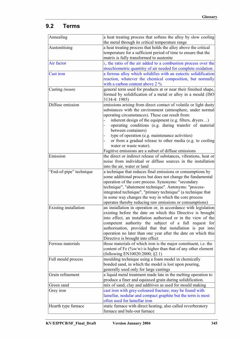
Glossary
KV/EIPPCB/SF_Final_Draft Version January 2004 345
9.2 Terms
Annealing a heat treating process that softens the alloy by slow coolingthe metal through its critical temperature range
Austenitising a heat treating process that holds the alloy above the criticaltemperature for a sufficient period of time to ensure that thematrix is fully transformed to austenite
Air factor λ, the ratio of the air added to a combustion process over thestoechiometric quantitiy of air needed for complete oxidation
Cast iron a ferrous alloy which solidifies with an eutectic solidificationreaction, whatever the chemical composition, but normallywith a carbon content above 2 %
Casting (noun) general term used for products at or near their finished shape,formed by solidification of a metal or alloy in a mould (ISO3134-4: 1985)
Diffuse emission emissions arising from direct contact of volatile or light dustysubstances with the environment (atmosphere, under normaloperating circumstances). These can result from:- inherent design of the equipment (e.g. filters, dryers…)- operating conditions (e.g. during transfer of material
between containers)- type of operation (e.g. maintenance activities)- or from a gradual release to other media (e.g. to cooling
water or waste water).Fugitive emissions are a subset of diffuse emissions
Emission the direct or indirect release of substances, vibrations, heat ornoise from individual or diffuse sources in the installationinto the air, water or land
“End-of-pipe” technique a technique that reduces final emissions or consumptions bysome additional process but does not change the fundamentaloperation of the core process. Synonyms: "secondarytechnique", "abatement technique". Antonyms: "process-integrated technique", "primary technique" (a technique thatin some way changes the way in which the core processoperates thereby reducing raw emissions or consumptions)
Existing installation an installation in operation or, in accordance with legislationexisting before the date on which this Directive is broughtinto effect, an installation authorised or in the view of thecompetent authority the subject of a full request forauthorisation, provided that that installation is put intooperation no later than one year after the date on which thisDirective is brought into effect
Ferrous materials those materials of which iron is the major constituent, i.e. thecontent of Fe (%w/w) is higher than that of any other element(following EN10020:2000; §2.1)
Full mould process moulding technique using a foam model in chemicallybonded sand, in which the model is lost upon pouring,generally used only for large castings
Grain refinement a liquid metal treatment made late in the melting operation toproduce a finer and equiaxed grain during solidification.
Green sand mix of sand, clay and additives as used for mould makingGrey iron cast iron with grey-coloured fracture; may be found with
lamellar, nodular and compact graphite but the term is mostoften used for lamellar iron
Hearth type furnace static furnace with direct heating, also called reverberatoryfurnace and bale-out furnace

Glossary
346 Version January 2004 KV/EIPPCB/SF_Final_Draft
Inclusion (specific term for this sector) impurity in the metal structure,producing structural defects; mostly used for non-ferrousmetals (e.g. oxides in magnesium, hydrogen in aluminium)
Jungbüth or net diagram diagram representing the influence of the blast rate and thecoke charge on the tapping temperature of the metal and themelting rate; used for cupola furnaces
Lamellar iron cast iron with carbon in the form of flakesLost Foam process moulding technique using foam models in unbonded sand, in
which the model is lost upon pouring of the metal, used forseries production
Lost mould or single use moulds, a mould that is specially made for eachcasting and is destroyed after pouring. The moulds aregenerally made of sand, chemically-bonded or clay-bonded,or even unbonded. Investment casting can also be included inthis family
Lost mould casting all processes of the moulding and casting shop in a foundryusing lost moulds, such as sand preparation, moulding, core-making, pouring, cooling and shake-out
Malleable iron iron that is capable of extension or of being shaped under thehammer; produced by decarburising (whiteheart malleableiron) or not decarburising (blackheart malleable iron) heattreatment of graphite-free iron with white fracture surface(white cast iron)
Melting capacity the aggregate ‘plated’ capacity of the furnaces at aninstallation; where the hourly rate multiplied by 24 should beused if appropriate
Modulus silica-to-soda ratio SiO2/Na2O, used to characterise (sodium)silicates
Nodular iron cast iron with carbon in nodular/spheroidal shape, commonlyrefered to as ductile iron
Nodularisation magnesium treatment of cast iron to change the carbonparticles into nodular/spheroidal shape
Non-ferrous materials all materials that are not ferrousNormalising a heat treating process that cools the alloy in air from a
temperature above its critical rangeOff-site sand re-use utilisation of sands in various waysPermanent mould or multi use a mould, mould that is used for gravity and low-
pressure casting, pressure die-casting, or centrifugal casting;typically the moulds are metallic
Permanent mould casting all processes of the coreshop and casting shop in a foundryusing permanent moulds, such as sand preparation, core-making, die-casting, take-out and decoring
Pollutant individual substance or group of substances which can harmor affect the environment
Post combustion ignition and burning of exhaust gas through the injection ofair or the use of a burner; used in order to reduce the amountof CO and (volatile) organic compounds
Primary regeneration the processing of used green sand for internal re-use in thesand circuit, using screening, sieving, cooling and mixingwith new sand, fresh bentonite and other additives
Production capacity production of ‘good castings’ and capacity based on thetheoretical capacity of the foundry if it was operated for 24hours, provided that it is technically able to operate that way
Regeneration ratio the ratio between the mass of regenerated sand and the totalmass of sand used in mould and core-making, expressed as apercentage

Glossary
KV/EIPPCB/SF_Final_Draft Version January 2004 347
Sand circuit the various parts of the installation for storage, transport,preparation and treatment of sand
Sand recycling on-site used-sand preparation, for external re-useSecondary (sand)regeneration
measures (mechanical, pneumatic, thermal and wet) aimed atremoving spent binder layers from the sand corn (=reclamation); returning the sand to a quality similar to, orbetter than, new sand
Steel a ferrous alloy which solidifies according a preritetic reaction.The (mass) content of iron is bigger than that of any otherelement, and the carbon content is generally lower than 2%;the alloy also usually contains other elements
Tempering a heat treatment that after the hardening of the alloy consistsof heating to a temperature below Ac1 and cooling in air; afteraustenitising and liquid quenching, this provides to the alloythe highest possible hardness and strength

Glossary
348 Version January 2004 KV/EIPPCB/SF_ Final_Draft
9.3 LexiconEnglish Deutsch Français Nederlands Español Italiano Magyarbentonite Bentonit bentonite bentoniet bentonita bentonite bentonitbridging Brückenbildung accrochage brugvorming colgadura formazione di corona adagfennakadásburr Grat barbe braam rebarba bava fánccast iron Gusseisen fonte gietijzer hierro ghisa öntöttvascast steel Stahlguss acier moulé gietstaal acero moldeado getti d'acciaio öntött acélcasting Giessen couler het gieten fundición colata öntéschamfer Abschrägung chanfrein gietsysteem chaflán cianfrinatura formázási ferdeségchannel induction furnace Rinnenofen four à induction à canal kanaal inductieoven horno de inducción de
canalforno a canale csatornás indukciós kemence
coating Schlichte enduit, poteyage coating/deklaag pintura vernice, verniciatura formabevonó anyagcold-box kalter Kernkaste, Cold-
boxboîte froide cold-box caja fria cassa fredda cold-box
core Kern noyau kern macho anima magcorebox Kernkasten boîte à noyaux kerndoos caja de macho cassa d'anima magszekrénycore-making Kernfertigung noyautage kernmakerij macheria formatura di anime magkészítéscrucible furnace Tiegelofen four à creuset kroesoven horno de crisol forno a crogiolo tégelykemencedecoring Entkernen debourrage ontkernen extracción de macho sterratura delle anime kimagozásdie Druckgiessform moule vorm mole metálico stampo kokilla, nyomásos öntőformadie lubricant Druckgiessschlichte poteyage koelsmeermiddel lubricante distaccante kokilla-, nyomásos öntőforma
kenőanyagdrying oven Backofen étuve droogstoof estufa essiccatore szárító kemencefettling putzen ébarbage ontbramen desmazarotado sbavatura tisztításgrinding schleifen meulage slijpen esmerilada molatura csiszolás, köszörülésinduction furnace Induktionsofen four à induction inductieoven horno de inducción forno ad induzione indukciós kemencelamellar iron or grey castiron
Grauguss, GGL fonte lamellaire,fonte grise
lamellair gietijzer hierro gris ghisa a grafitelamellare,ghisa grigia
lemezgrafitos vagy szürke öntöttvas
lustrous carbon Glanzkohlenstoff carbone brillant glanskoolvormer carbono brillante carbonio brillante fényes karbonmalleable iron temperguss (GT) fonte malléable smeedbaar gietijzer fundición maleable ghisa malleabile tempervasmixer Menger malaxeur menger mezclador mescolatore keverőmould Form mote vorm molde forme formanodular iron, ductile iron,SG iron
GGG,Gusseisen mitKugelgraphit
fonte à graphitesphéroidal,fonte ductile
nodulair gietijzer hierro nodular ghisa sferoidale gömbgrafitos öntöttvas
pouring Giessen couler gieten colada colata öntéssand Sand sable zand arena sabbia homok

Glossary
KV/EIPPCB/SF_Final_Draft Version January 2004 349
English Deutsch Français Nederlands Español Italiano Magyarshaft furnace Schachtofen four à cuve schachtoven horno de cuba forno a tino aknás kemenceshake-out Ausleeren décochage uitschudden desmoldeo distaffatura ürítés, kirázásshot blasting Schleuderstrahlen grenaillage gritstralen granallado granigliatura szemcseszórássprue Einguss canal de coulée voedingskanaal canal de colada canale di colata álló beömlőturnings Späne copeaux spanen viruta trucioli forgácsveins rissen gerces vinnen venas crestine repedések


Annex
KV/EIPPCB/SF_Final_Draft Version January 2004 351
10 ANNEXES
10.1 Annex 1 Overview of data for cast iron melting invarious cupola types and in the induction furnace
A survey of the consumption and emission levels of the various technical modifications ofcupola melting was set up by Neumann in 1994, as given below. All data refer to a system forthe production of 10 tonne/h nodular iron with 3.6 % C and 1.6 % Si and at a pouringtemperature of 1530 ºC. The balances in Figure 10.1 show inputs, outputs and processtemperatures. The latter will be higher compared to operational practice. Comparison of thevarious balances allows an assessment of the effect of all the modifications.
Additional operational data for cold and hot blast cupolas, with various flue-gas cleaningequipment types, are given and discussed in Section 4.5.2. Those data are taken from operatingplants.
The pictures show the following techniques:
(A): cold blast, secondary row of tuyères(B): cold blast, oxygen injection(C): cold blast with gas burner, oxygen injection(D): hot blast (500 ºC), long campaign(E): hot blast with electrical support heating (750 ºC)(F): hot blast, oxygen injection (6 %)(G): hot blast, with plasma support heating (1450 ºC)(H): cokeless cupola in duplex operation (electrical superheating).
A B

Annex
352 Version January 2004 KV/EIPPCB/SF_Final_Draft
C D
E F

Annex
KV/EIPPCB/SF_Final_Draft Version January 2004 353
G H
Figure 10.1: Input-output balance for various technical modifications of cupola melting[172, Neumann, 1994]
Operational data are given in Table 10.1, Table 10.2 and Table 10.3. These include economicdata based on the stated unit costs. Operational data are based on the production of a cast ironwith 3.3 % C and 2 % Si. In the cold blast operation 35 % steel scrap is used, while the hot blastoperation allows 60 %. This is taken into account when considering the necessary carburisation.For this, C is also supplied through the addition of the SiC briquettes.
Calculation of the heat balance results in the stated heat transfer efficiencies. The cold blastcupola shows an efficiency of <30 %. The application of oxygen or secondary air increases theefficiency to 37 – 40 %. The hot blast cupola shows a further increased efficiency, providing thefurnace wall is refractory lined. In liningless operation, the efficiency drops below 40 %, whichmay be somewhat compensated for by adding oxygen. The cokeless cupola with inductivesuperheating results in a very high efficiency, close to 60 %.
The calculated operational costs include depreciation of the investment cost, but excludepersonnel costs. The cost difference between the various techniques is rather small. Thecalculation takes account of higher cokes consumption and more expensive scrap/raw materialcosts for the cold blast cupola. In the case of air preheating using a plasma torch, the increasedelectricity use leads to increased costs. In practice, this increase may be balanced by anincreased usage of swarf as raw material. The cokeless cupola shows the lowest cost. In thisevaluation, however, local cost effects and uncertainties, such as the effect of hourly rate, havenot been taken into account, but need to be considered. The quoted data are all for installationswith a significant hourly rate. This disfavours the performance of cold blast cupolas.

Annex
354 Version January 2004 KV/EIPPCB/SF_Final_Draft
Units orCost per unit
Normal O2 Second-ary row
Second-ary + O2
Specific quantityMelting cokes kg/tonne 150 125 120 105Cokes for carburisation kg/tonne 10 10 10 10Natural gas m3/tonneElectricity kWh/tonne 20 20 20 20Oxygen % - 3 - 2Blast air m3/tonne 711 562 604 517Cupola off-gas m3/tonne 902 724 731 628Filtered off-gas m3/tonne 3022 2150 1765 1646Slags kg/tonne 36 35 46 45Refractory kg/tonne 5.2 5.2 4.8 4.8SiC- briquettes(45 % SiC) kg/tonne 28.5 28.5 31.3 30.3Total heat input MJ/tonne 5003 3643 3588 3416Heat transfer to iron % 26.9 37.2 37.8 39.8CostsInvestment EUR million 2.81 2.91 3.06 3.16Alloy EUR 332/tonne 9.44 9.44 10.36 10.36Additives EUR 10/tonne 0.20 0.20 0.20 0.20Cokes EUR 204/tonne 32.65 27.55 26.53 23.47Steel scrap EUR 128/tonne 44.64 44.64 44.64 44.64Scrap iron EUR 128/tonne 12.76 12.76 12.76 12.76Pig iron EUR 194/tonne 38.78 38.78 38.78 38.78Natural gas EUR 153/1000 m3 0.31 0.31 0.31 0.31Electricity EUR 89/MWh 1.79 1.79 1.79 1.79Oxygen EUR 179/1000 m3 - 3.01 - 1.84Graphite EUR 561/tonne - - - -Refractory EUR 765/tonne 3.98 3.98 3.67 3.67Capital 10 years/8 % 11.22 11.63 12.24 12.65Total melting cost EUR/tonne 155.77 154.08 151.28 150.46Iron composition: 3.3 % C; 2.0 % Si; 0.3 % Mn; 0.1 S; 1500 ºCLoad composition: 35 % steel scrap; 35 % returns; 20 % pig iron; 10 % scrap iron
Table 10.1: Operational data of a cold blast cupola (10 tonne/h)[172, Neumann, 1994]

Annex
KV/EIPPCB/SF_Final_Draft Version January 2004 355
Units orCost per unit
Type A* Type B Type C Type D Type E
CharacteristicsDaily furnace changeOxygen enrichmentLining
YesNoYes
NoNoYes
NoYesYes
NoNoNo
NoYesNo
Specific quantityMelting cokes kg/tonne 95 100 85 115 100Cokes for carburisation kg/tonne 8 7 7 8 8Oxygen % - - 3 - 3Air m3/tonne 571 566 425 626 473Cupola off-gas m3/tonne 680 667 519 746 586Filtered gas m3/tonne 1798 1471 1134 1819 1473Slag kg/tonne 60 60 60 60 60Refractory kg/tonne 15 6 6 1.5 1.5SiC- briquettes(45 % SiC) kg/tonne 50 53 53 50 50Total heat input MJ/tonne 3756 3630 3076 4098 3534Heat transfer to iron % 39.8 40.2 44.9 36.5 38.7CostsInvestment EUR million 3.42 3.57 3.65 3.49 3.55Alloy EUR 332/tonne 16.58 17.60 17.60 16.58 16.58Additives EUR 10/tonne 0.20 0.20 0.20 0.20 0.20Cokes EUR 204/tonne 21.02 21.84 18.78 25.10 22.04Scrap steel EUR 128/tonne 76.53 76.53 76.53 76.53 76.53Scrap iron EUR 128/tonne 12.76 12.76 12.76 12.76 12.76Oxygen EUR 179/1000 m3 - - 3.06 - 3.42Refractory EUR 765/tonne 11.48 4.59 4.59 1.12 1.12Capital 10 years/8 % 13.67 14.29 14.59 13.98 14.18Total melting cost EUR/tonne 152.24 147.81 148.11 146.28 146.84* Is no longer built as new plantIron Composition: 3.3 % C; 2.0 % Si; 0.3 % Mn; 0.1 S; 1530 ºCLoad composition: 60 % steel scrap; 30 % returns; 10 % scrap iron
Table 10.2: Operational data of a hot blast long campaign cupola (10 tonne/h)[172, Neumann, 1994]

Annex
356 Version January 2004 KV/EIPPCB/SF_Final_Draft
Hot blast cupolaUnits or
Cost per unit
CokelessCupola
with O2 +induct.superh.
air preh.using
plasma
air preh.using
electricresistance
Specific quantityMelting coke kg/tonne - 81 90Coke for carburisation kg/tonne - 10 12Natural gas m3/tonne 55 2 2Electricity kWh/t 80 175 82Oxygen % 1.5 - -Air m3/tonne 5.30 419 474Cupola off-gas m3/tonne 692 451 531Cleaned off-gas m3/tonne 815 1313 1264Slags kg/tonne 58 59 60Refractory kg/tonne 16 9.3 4.3SiC- briquettes (45 % SiC) kg/tonne - 13.7 15.4FeSi- briquettes(1 kg Si per briquette)
kg/tonne 8 - -
Total heat input MJ/tonne 2562 3952 3320Heat transfer to iron % 58.4 41.4 41.5CostInvestment EUR million 2.81 5.10 3.83Alloy EUR 332/tonne 4.54 5.10Fe-Si-briquettes EUR 454/tonne Si 3.62Additives EUR 10/tonne 0.56 0.56 0.56Cokes EUR 204/tonne 18.57 23.06Electricity EUR 89/MWh 7.14 15.61 7.30Gas EUR 128/1000 m3 6.99 0.31 0.31Scrap steel EUR 128/tonne 44.64 44.64 44.64Scrap iron EUR 128/tonne 44.64 44.64 44.64Graphite EUR 561/tonne 6.73Oxygen EUR 179/1000 m3 1.43Refractory EUR 102/tonne 0.61 0.31 0.20Refractory EUR 765/tonne 7.65 4.80 1.79Capital 10 years/8 % 11.22 20.41 15.31Total melting cost EUR/tonne 135.26 154.39 142.91Iron composition: 3.3 % C; 2.0 % Si; 0.3 % Mn; 0.1 S; 1530 ºCLoad composition: 35 % steel scrap; 30 % returns; 35 % scrap iron
Table 10.3: Operational data of a cokeless cupola and hot blast cupola with air preheating[172, Neumann, 1994]
CTIF also calculated the costs of liquid cast iron in a comparative study about the differentmelting ways [226, CTIF, 1997]. This study, made in 1997, was updated in 2003 [227, Godinot,2004].

Annex
KV/EIPPCB/SF_Final_Draft Version January 2004 357
GRADELamellar cost iron (ENGJL 250) Nodular cost iron (ENGJS 400 – 15)
UnitsMelting device
Cold blastcupola
Hot blastcupola
Cokelesscupola
Inductionfurnace
Hot blastcupola
Cokelesscupola
Inductionfurnace
Metallic charge 95.80 59.52 96.68 72.97 49.75 73.52 59.80Ferro alloys + additives 7.62 13.09 27.22 25.72 5.27 24.17 24.85Energy and fluids 33.14 35.26 20.29 27.28 40.12 21.07 27.28Linings 3.73 4.29 8.79 1.47 4.55 8.79 1.47Personnel costs 10.05 10 11 9.10 10.42 11 9.10Maintenance 1.55 3.15 0.16 0.93 3.15 0.16 0.93Environment 4.50 4.30 3.15 0.55 4.30 3.15 0.55Desulphurisation 10.33Depreciation of investment 5.92 14.81 8.89 8.89 14.81 8.89 8.89
EUR/t
Total per tonne charged 162.31 144.42 176.78 146.91 142.70 150.75 132.97% Fire loss 5 5 5 3 5 5 3EUR/t Total per tonne liquid 170.85 152.02 185.45 151.45 150.21 158.68 136.98% Returns percentage 35 40 35 40 50 50 50EUR/t Total per tonne of casting 262.85 253.36 285.31 252.42 300.42 317.37 273.96
Table 10.4: Comparison of liquid cast iron costs -June 2003. Mass production – 10 t/h

Annex
358 Version January 2004 KV/EIPPCB/SF_Final_Draft
Cold blast cupola Induction Coreless furnace Hot blast cupola Cokeless cupolaCharacteristic Unit Price
EUR/unitRatio Price
EUR/tPrice
EUR/unitRatio Price
EUR/tPrice
EUR/unitRatio Price
EUR/tPrice
EUR/unitRatio Price
EUR/tPrice
EUR/unitRatio Price
EUR/tCokeElectricityOxygenGas
tonnekWhNm3
kWh(NCV)
2100.05130.535
0.0296
0.145202
20
30.451.0271.070.59
0.0448 609 27.28 0.0448 609 27.28210
0.05130.5350.228
0.125128
260
26.256.571.071.37
0.05130.23
0.0186
16511
500
8.462.539.30
Sub total 33.14 27.28 27.28 35.26 20.29ReturnsPig ironScrap ironScrap steel (E3)Scrap steel (E8)Scrap steel (E1 C)
tonnetonnetonnetonnetonne
0185167
101.5
0.350.200.200.25
037
33.425.4
0185
101.599.5
0.400.15
0.2250.225
027.75
22.8322.39
0200
99.5
0.500.10
0.40
020
39.80
0
101.5
96.9
0.40
0.30
0.30
0
30.45
29.07
0185167
101.5
0.350.250.150.25
046.2525.0525.38
Sub total 95.8 72.97 59.80 59.52 96,68GraphiteFeSiFeMnCaCO3 + divBalls
kgkg Si
kg Mntonnetonne
0.680.59512.2
82.7
0.048
5.441.600.58
0.701.130.79
16.710.62.6
11.6911.982.05
0.801.13
17.929.39
14.3410.61 0.68
0.5912.2
15.83.2
0.0375
10.741.890.46
0.70.68
0.595
8.1211. 711.45
5.687.960.86
12.72
Sub total 7.62 25.72 24.95 13.09 27.22
Table 10.5: Price of lamellar cast iron: Metallic charge + energy

Annexes
KV/EIPPCB/SF_Final_Draft Version January 2004 359
Hot blast cupola Cokeless cupolaUnitsPrice
EUR/unitRatio Price
EUR/tPrice
EUR/unitRatio Price
EUR/tCokeElectricityOxygenGas
tonnekWhNm3
kWh(NCV)
2100.05130.535
0.0228
0.14140.5
460
29.407.212.141.37
0.05130.23
0.0186
18011
500
9.232.539.30
Sub total 40.12 21.07ReturnsPig ironScrap ironScrap steel (E8)Scrap steel (E3)
tonnetonnetonnetonnetonne
0
99.55
0.40
0.50
0
49.75
0199167
101.5
0.400.200.05
0.25
039.88.35
25.38Sub total 49.75 73.52GraphiteFeSiFeMnCaCO3 + divBalls
kgkg Si
kg Mntonnetonne
0.68
12.2
7
0.042
4.76
0.51
0.70.68
12.374.11
8.662.79
12.72
Sub total 5.27 24.17
Table 10.6: Price of nodular cast iron: Metallic charge + energy
Table 10.4 summarises the costs of cast iron calculated for the 3 main cupola types comparedwith coreless induction furnace. Some items greatly depend on the melting device and thegrade: energies and fluids, metallic charge and ferro alloys. They are detailed in Table 10.5 andTable 10.6.
The compared melting devices melt at 10 - 12 t/h, in 2 shifts for a mass production typically,e.g. the automotive industry. The investments are paid in 10 years and correspond to theindustrial practice in each case, i.e.:
Cold blast cupola- 2 daily drop cupolas (one per day)- treatment of fumes: combustion, cooling, dry filtration.
Hot blast cupola- long campaign cupola- treatment of fumes: combustion, blast heating, cooling, dry filtration- holding in a channel induction furnace.
Cokeless cupola- long campaign cupola- treatment of fumes: cooling, dry filtration- heating and recarburisation in a superheater- holding in a channel induction furnace.
Introduction furnace- 2 furnaces 12 tonne- 1 power supply 10MW – 250 Hz.
The cost of cast iron must take into account its downstream recarburisation (cokeless cupola),its holding and also the importance of the fume treatment system.
The price of cast iron was compared for 2 different alloys in the case of mass automotiveindustry:
- lamellar cast iron (ENGJL 250)- nodular graphite base cast iron (base for ENGJS 400-15).

Annexes
360 Version January 2004 KV/EIPPCB/SF_Final_Draft
The cold blast cupola is increasingly less used for nodular cast iron and was not considered inthis case.
Comparing the calculations of CTIF and Neumann:
The position of the melting devices, from the least to the most expensive, is not the samedepending on the type of alloy and the authors:
- Lamellar graphite cast iron (LG cast iron)CTIF: induction furnace, hot blast, cold blast, cokeless cupolaNeumann: cokeless, hot blast, cold blast cupola
- Nodular base cast ironCTIF: induction furnace, hot blast, cokeless (little different).
The comparison of the different items for Neumann and Godinot leads to the followingconclusions:
1. Energies and fluids- the cokeless cupola is the least expensive in all cases- it is noticeable that the energy costs strongly depend on the country, particularly with regard
to the price and availability of electricity and gas. In the CTIF study, energy costscorrespond to the French case (prices published in the review “Energy Plus”).
2. Metallic charges and ferro alloysThe classification technique applied of disadvantages the cokeless cupola for CTIF and not forNeumann. The principal differences are the following ones:
- Neumann indicates 0 % pig iron for cokeless cupola, when Godinot indicates a minimum of25 % according to the industrial practice. Pig iron is the most expensive metallic charge.
- Neumann gives the same cost for steel scrap and cast iron scrap. In the French case, theratio between these 2 costs has been between 2 and 1.3 for 10 years. This ratio was 1.6 inJune 2003, the date considered for the calculation, as indicated in the attached Figure 10.2.
It is noticeable that the cost of raw materials, including scrap, are fixed today at an internationallevel.
0.0
50.0
100.0
150.0
200.0
250.0
Jan-93
Jul-9
3
Jan-94
Jul-9
4
Jan-95
Jul-9
5
Jan-96
Jul-9
6
Jan-97
Jul-9
7
Jan-98
Jul-9
8
Jan-99
Jul-9
9
Jan-00
Jul-0
0
Jan-01
Jul-0
1
Jan-02
Jul-0
2
Jan-03
Cos
t (EU
R /
tonn
e)
SG pig iron
Lamellarpig iron
Scarpiron (VF2)
Scrapsteel (E1C)
Figure 10.2: Cost of raw materials (France: 1993 to 2003)

Annexes
KV/EIPPCB/SF_Final_Draft Version January 2004 361
3. Other itemsThe investment is less important than for cold blast, cokeless cupola and coreless inductionfurnace.- in the case of the cold blast cupola liquid, cast iron is produced at a good temperature and
analysis is possible at the spout of the cupola; moreover the metallurgical results dependlittle on the hourly production. It is not necessary to hold the cast iron in a channel inductionfurnace
- in the case of the hot blast cupola, or of the cokeless cupola, it is difficult to modify thehourly production. A reservoir of liquid metal is necessary between the cupola and themoulding shop, i.e. generally a channel induction furnace
- in the case of the cokeless cupola, the specific volume of fumes to be treated is low and it isnot necessary to burn CO
- finally, in the case of the coke cupola (hot or cold blast), a desulphurisation is generallypractised before holding the base nodular liquid cast iron. The cost of this operation is high,which is favours the cokeless cupola, whose cast iron does not contain any sulphur.
4. ConclusionTaking industrial practice into account, according to Godinot, the cokeless cupola has theadvantage of a low energy consumption but it incurs extra cost for the raw charging materials.
In the case of base nodular cast iron, the cokeless cupola produces a metal without sulphur andwith a cost level similar to the hot blast. In the case of lamellar cast iron, in France, this meltingdevice produces a more expensive metal than coke cupolas.
Today, for this type of production in France the limit between cupola and induction is 10 t/h(lamellar cast iron) and probably more in the case of nodular cast iron (the cupola is lessexpensive for 20 t/h).
These calculations have been made for an automotive type mass production. For otherapplications, they need to be slightly modified. At least it is possible to say the relative orderdepends on the local conditions, especially energy costs which depend strongly on the countryof application.
10.2 Annex 2 Dust control equipment at a large-scaleautomotive foundry
Dust emission monitoring data were provided by a Swedish large-scale automotive foundry.The foundry uses a continuous particulate emission monitoring system on 17 bag filter exhausts.Data were plotted on a graph for various time ranges and for 4 measurement points as shown inFigure 10.3, Figure 10.4 and Figure 10.5. The figures show a continuous dust level well below1 mg/Nm³ for sand preparation and shot blasting. A 24h-average of 1.3 – 1.6 mg/Nm³ wasobtained for the sand transport.

Annexes
362 Version January 2004 KV/EIPPCB/SF_Final_Draft
Figure 10.3: Monitoring data for dust emissions from 4 locations in the sand plant (24 hourscontinuous monitoring)
Figure 10.4: Monitoring data for dust emissions from 4 locations in the sand plant (2 weekscontinuous monitoring)

Annexes
KV/EIPPCB/SF_Final_Draft Version January 2004 363
Figure 10.5: Monitoring data for dust emissions from 4 locations in the sand plant (30 dayscontinuous monitoring)
This example plant has a permitted emission limit value for dust of 10 mg/Nm³. The monitoringsystem has an alarm limit of 5 mg/Nm³. If this limit is passed, the filter is checked and testedwith fluorescence material. If the measured value passes 10 mg/Nm³, the production and filterare stopped. Calibration of the monitoring equipment is performed twice a year by an externalcontractor.
The service and maintenance instructions are as follows:- daily
� pressure drop check� visual check� magnetic valve check� condensation water drain
- monthly� check tightness
- quarterly (every 3 months)� control with fluorescence material.


![The Daughter of God is a masterwork [0064-19-4488]](https://static.fdocuments.us/doc/165x107/577cddd01a28ab9e78adcc0a/the-daughter-of-god-is-a-masterwork-0064-19-4488.jpg)