EdgeFire™ - Trend Micro
93
EdgeFire™ Administrator’s Guide Copyright © 2020 Trend Micro Incorporated. All rights reserved. No part of this publication may be reproduced, photocopied, stored in a retrieval system, or transmitted without the express prior written consent of Trend Micro Incorporated. 2020-10-12
Transcript of EdgeFire™ - Trend Micro

EdgeFire™
Administrator’s Guide
Copyright © 2020 Trend Micro Incorporated. All rights reserved. No part of this publication may
be reproduced, photocopied, stored in a retrieval system, or transmitted without the express prior
written consent of Trend Micro Incorporated.
2020-10-12

2
Trend Micro Incorporated reserves the right to make changes to this document and to
the product described herein without notice. Before installing and using the product,
review the readme files, release notes, and/or the latest version of the applicable
documentation, which are available from the Trend Micro website at:
http://docs.trendmicro.com/en-us/home.aspx
Trend Micro, the Trend Micro t-ball logo, and TXOne Networks are
trademarks or registered trademarks of Trend Micro Incorporated. All other product or
company names may be trademarks or registered trademarks of their owners.
This documentation introduces the main features of the product and/or provides
installation instructions for a production environment. Read through the documentation
before installing or using the product.
Detailed information about how to use specific features within the product may be
available at the Trend Micro Online Help Center and/or the Trend Micro Knowledge
Base.

3
Table of Contents Table of Contents ..................................................................................................................................... 3
Chapter 1 .................................................................................................................................................. 7
About EdgeFire ........................................................................................................................................ 7
Introduction .......................................................................................................................................... 7
Main Functions ..................................................................................................................................... 8
Extensive Support for Industrial Protocols ..................................................................................... 8
Policy Enforcement for Mission-Critical Machines........................................................................ 8
Improve Shadow OT Visibility by Integrating IT and OT Networks ............................................. 8
Intrusion Prevention and Intrusion Detection ................................................................................. 8
Switch Between Two Flexible Modes, ‘Monitor’ & ‘Prevention’ .................................................. 8
Top Threat Intelligence and Analytics ............................................................................................ 8
Centralized Management ................................................................................................................ 8
Flexible Segmentation and Isolation ............................................................................................... 9
Chapter 2 ................................................................................................................................................ 10
Getting Started ........................................................................................................................................ 10
Getting Started: Task List ................................................................................................................... 10
Opening the Management Console ..................................................................................................... 11
Changing the Administrator’s Password ............................................................................................ 12
Chapter 3 ................................................................................................................................................ 13
The System Tab ...................................................................................................................................... 13
Device Information ....................................................................................................................... 13
Secured Service Status .................................................................................................................. 13
System Resources ......................................................................................................................... 14
WAN Interface Summary ............................................................................................................. 14
LAN Interface Summary............................................................................................................... 15
Throughput / Connection .............................................................................................................. 15
Chapter 4 ................................................................................................................................................ 16
The Visibility Tab................................................................................................................................... 16
Active Query ...................................................................................................................................... 16
Viewing Asset Information ................................................................................................................ 16
Viewing Real Time Network Application Traffic .............................................................................. 17

4
Chapter 5 ................................................................................................................................................ 18
The Network Tab .................................................................................................................................... 18
Port Settings ....................................................................................................................................... 18
Configuring the Ports .................................................................................................................... 18
Port Mapping ...................................................................................................................................... 19
Viewing the Port Mapping ............................................................................................................ 19
Network Interface ............................................................................................................................... 20
Configuring LAN Network Interface ............................................................................................ 20
Configuring DMZ Network Interface ........................................................................................... 23
Configuring WAN Network Interface .......................................................................................... 24
Operation Mode .................................................................................................................................. 27
Gateway Mode .............................................................................................................................. 27
Bridge Mode ................................................................................................................................. 27
Switch from Gateway Mode to Bridge Mode ............................................................................... 28
Switch from Bridge Mode to Gateway Mode ............................................................................... 29
Chapter 6 ................................................................................................................................................ 31
The NAT Tab ......................................................................................................................................... 31
NAT Rule ........................................................................................................................................... 31
Configuring a 1 to 1 NAT Rule .................................................................................................... 31
Configuring a Multiple 1 to 1 NAT Rule ...................................................................................... 32
Configuring Port Forwarding ........................................................................................................ 34
ALG .................................................................................................................................................... 35
Configuring ALG Settings ............................................................................................................ 35
Chapter 7 ................................................................................................................................................ 37
The Routing Tab ..................................................................................................................................... 37
Static Route ........................................................................................................................................ 37
Configuring a Static Route............................................................................................................ 37
Chapter 8 ................................................................................................................................................ 39
The Object Profiles Tab.......................................................................................................................... 39
Configuring IP Object Profile............................................................................................................. 39
Configuring Service Object Profile .................................................................................................... 40
Configuring Protocol Filter Profile ..................................................................................................... 41

5
Specifying Commands Allowed in an ICS Protocol ..................................................................... 42
Applying the Drop Malformed Option to an ICS Protocol ........................................................... 42
Advanced Settings for Modbus Protocol ...................................................................................... 43
Advanced Settings for CIP Protocol ............................................................................................. 45
Advanced Settings for S7Comm ................................................................................................... 48
Advanced Settings for S7Comm Plus ........................................................................................... 51
Advanced Settings for SLMP ....................................................................................................... 54
Advanced Settings for MELSOFT ................................................................................................ 57
Advanced Settings for TOYOPUC ............................................................................................... 60
Configuring IPS Profile ...................................................................................................................... 63
Configuring a Pattern Rule for Granular Control.......................................................................... 64
Chapter 9 ................................................................................................................................................ 66
The Security Tab .................................................................................................................................... 66
Cyber Security .................................................................................................................................... 66
Configuring Cyber Security – Denial of Service Prevention ........................................................ 66
Policy Enforcement ............................................................................................................................ 67
Configuring Policy Enforcement .................................................................................................. 67
Adding Policy Enforcement Rules (In Gateway Mode) ............................................................... 67
Adding Policy Enforcement Rules (In Bridge Mode) ................................................................... 70
Managing Policy Enforcement Rules............................................................................................ 72
Chapter 10 .............................................................................................................................................. 74
The Pattern Tab ...................................................................................................................................... 74
Viewing Device Pattern Information .................................................................................................. 74
Manually Updating the Pattern ........................................................................................................... 74
Chapter 11 .............................................................................................................................................. 75
The Log Tab ........................................................................................................................................... 75
Viewing Cyber Security Logs ............................................................................................................ 75
Viewing Policy Enforcement Logs ..................................................................................................... 76
Viewing Protocol Filter Logs ............................................................................................................. 76
Viewing Asset Detection Logs ........................................................................................................... 77
Viewing System Logs......................................................................................................................... 77
Viewing Audit Logs ........................................................................................................................... 77

6
Chapter 12 .............................................................................................................................................. 79
The Administration Tab.......................................................................................................................... 79
Account Management ......................................................................................................................... 79
User Roles ..................................................................................................................................... 79
Built-in User Accounts ................................................................................................................. 80
Adding a User Account ................................................................................................................. 80
Changing Your Password.............................................................................................................. 80
Configuring Password Policy Settings .......................................................................................... 81
System Management .......................................................................................................................... 81
Configuring Device Name and Device Location Information ...................................................... 82
Configuring Control List Access for Management Clients ........................................................... 82
Configuring Management Protocols and Ports ............................................................................. 82
The Sync Settings Tab ........................................................................................................................ 83
Enabling Management by ODC .................................................................................................... 83
Configuring Syslog Settings ............................................................................................................... 83
Syslog Severity Levels .................................................................................................................. 85
Syslog Severity Level Mapping Table .......................................................................................... 85
Configuring System Time .................................................................................................................. 86
The Back Up / Restore Tab ................................................................................................................ 86
Backing Up a Configuration ......................................................................................................... 87
Restoring a Configuration ............................................................................................................. 87
The Firmware Management Tab ........................................................................................................ 87
Viewing Device Firmware Information ........................................................................................ 87
Updating Firmware ....................................................................................................................... 88
Rebooting and Applying Firmware............................................................................................... 89
Reboot System .................................................................................................................................... 89
Chapter 13 .............................................................................................................................................. 90
Supported USB Devices ......................................................................................................................... 90
Pattern Loading Function ................................................................................................................... 90
Appendix A ............................................................................................................................................ 93
Terms and Acronyms ............................................................................................................................. 93

7
Chapter 1
About EdgeFire
Introduction EdgeFire™, a next generation firewall, is a highly integrated industrial multiport secure router
with firewall, NAT, and IPS functions. It is designed for Ethernet-based security applications on
factory networks, and it provides an electronic security perimeter for the protection of critical
cyber assets including pump-and-treat systems in water stations, DCS systems in oil and gas
applications, and PLC/SCADA systems in factory automation. Users can access its web-based
console that provides a graphical user interface for device configuration and security policy
settings. The whole management process is designed to comply with the manufacturing SOPs of
the industry.
IT and OT traditionally are operated separately, each with its own network, transportation team,
goals, and needs. In addition, each industrial environment is equipped with tools and devices that
were not designed to connect to a corporate network, thus making provisioning timely security
updates or patches difficult. Therefore, the need for security products that provide proper security
protection and visibility is on the rise.
Trend Micro provides a wide range of security products that cover both your IT and OT layers.
These easy-to-build solutions provide an active and immediate protection to Industrial Control
System (ICS) environments with the following features:
▪ Certified industrial-grade hardware with size, power consumption, and durability tailored for
OT environments, as well as the ability to tolerate a wide range of temperature variations
▪ Threat detection and interception, with safeguards against the spread of worms
▪ Protection against Advanced Persistent Threats (APTs) and Denial of Service (DoS) attacks
that target vulnerable legacy devices
▪ Virtual patch protection against OT device exploits
Figure 1. Trend Micro security solutions for OT networks

8
Main Functions
EdgeFire(tm) is a security device which can be managed by the OT Defense Console. The main
functions of the product are as follows:
Extensive Support for Industrial Protocols
EdgeFire supports the identification of a wide range of industrial control protocols, including
Modbus and other protocols used by well-known international companies such Siemens,
Mitsubishi, Schneider Electric, ABB, Rockwell, Omron, and Emerson. In addition to allowing OT
and IT security system administrators to work together, this feature also allows the flexibility to
deploy defense measures in appropriate network segments and seamlessly connects them to
existing factory networks.
Policy Enforcement for Mission-Critical Machines
EdgeFire’s core technology TXODI allows administrators to maintain a policy enforcement
database. By analyzing Layer 3 to Layer 7 network traffic between mission-critical production
machines, policy enforcement executes filtering of control commands within the protocols and
blocks traffic that is not defined in the policy rules. This feature can help prevent unexpected
operational traffic, block unknown network attacks, and block other activity that matches a
defined policy.
Improve Shadow OT Visibility by Integrating IT and OT Networks
EdgeFire comes equipped to make your IT and OT networks as integrated and coordinated with
each other as possible, and to grant visibility of your shadow OT environment.
Intrusion Prevention and Intrusion Detection
IPS/IDS provides a powerful, up-to-date first line of defense against known threats. Vulnerability
filtering rules provide effective protection against all exploits at the network level. Manufacturing
personnel manage patching and updating, providing pre-emptive protection against critical
production failures, and additional protection for old or terminated software.
Switch Between Two Flexible Modes, ‘Monitor’ & ‘Prevention’
EdgeFire flexibly switches between ‘Monitor’ and ‘Prevention’ modes. ‘Monitor’ mode will log traffic
without interfering, while ‘Prevention’ mode will filter traffic based on policies you create. These
modes work together to preserve your productivity while maximizing security.
Top Threat Intelligence and Analytics
EdgeFire provides advanced protection against unknown threats with its up-to-date threat
information. With the help of the Zero Day Initiative (ZDI) vulnerability reward program, EdgeFire
offers your systems exclusive protection from undisclosed and zero-day threats.
Centralized Management
Trend Micro’s OT Defense Console (ODC) provides a graphical user interface for policy
management in compliance with manufacturing SOP. It centrally monitors operations information,
edits network protection policies, and sets patterns for attack behaviors.
All protections are deployed throughout the entire information technology (IT) and operational
technology (OT) infrastructure. These include:

9
▪ A centralized policy deployment and reporting system
▪ Full visibility into assets, operations, and security threats
▪ IPS and policy enforcement configuration can be assigned per device group, allowing all
devices in the same device group to share the same policy configuration
▪ Management permissions for device groups can be assigned per user account
Flexible Segmentation and Isolation
EdgeFire is the ideal solution for segmenting a network into easily managed security zones. It
segments networks and isolates connectivity both to and between facilities as well as production
zones. EdgeFire comes equipped to make your IT and OT networks as integrated and coordinated
with each other as possible, and to grant visibility of your shadow OT environment.

10
Chapter 2
Getting Started
This chapter describes the EdgeFire™ and how to get started with configuring the initial settings.
Note: For an overview of the physical hardware and characteristics or a condensed version of
help with initial setup of the device, please refer to the EdgeFire Quick Setup Guide
Getting Started: Task List
The Getting Started Task List provides a high-level overview of all procedures required to get
EdgeFire™ up and running as quickly as possible. Each step links to more detailed instructions
later in the document.
Procedure
1. Open the management console.
For more information, see Opening the Management Console on page 11.
2. Change the administrator password.
For more information, see Changing the Administrator’s Password on page 12.
3. Ensure that the link speed modes of the network ports are correct for your environment.
For more information, see Configuring the Ports on page 18.
4. Change the default web management console IP address.
The default web management console IP address is 192.168.127.254. The IP address is
bound to LAN1 network interface. To change the default IP address, see Configuring LAN
Network Interface on page 20.
5. Configure the network interfaces.
For more information, see The Network on page 20.
6. Configure the system time.
For more information, see Configuring System Time on page 86.
7. (Optional) Configure the Syslog settings.
For more information, see Configuring Syslog Settings on page 83.
8. Configure Object Profiles.
For more information, see The Object Profiles on page 39.
9. Configure security policies.
For more information, see The Security on page 66.
10. Configure the device name and device location information.
For more information, see Configuring Device Name and Device Location Information on page
82.
11. (Optional) Configure access control list from management clients.
For more information, see Configuring Control List Access for Management Clients on page
82.
12. (Optional) Configure management protocols and ports.
For more information, see Configuring Management Protocols and Ports on page 82.
13. (Optional) Update the DPI (Deep Packet Inspection) pattern for the device.
For more information, see Manually Updating the Pattern on page 74.
14. (Optional) Enabling Management by ODC.
For more information, see Enabling Management by ODC on page 83.

11
15. (Optional) Configuring password policy.
For more information, see Configuring Password Policy Settings on page 81.
Opening the Management Console
EdgeFire™ provides a built-in management web console that you can use to configure and
manage the product. View the management console using a web browser.
Note: View the management console using Google Chrome version 63 or later; Firefox version
53 or later; Safari version 10.1 or later; or Edge version 15 or later.
Procedure
1. In a web browser, type enter the address of the EdgeFire™ in the following format:
https://192.168.127.254
The logon screen will appear.
Note: The default IP address of EdgeFire™ is 192.168.127.254 with subnet 255.255.255.0.
Before connecting a PC/Laptop to EdgeFire™, the PC's IP address should be set to an IP
address that is able to access the default IP address. After that, connect the PC and
EdgeFire™ using an Ethernet cable.
2. Input the logon credentials (user name and password).
Use the default administrator logon credentials when logging on for the first time:
▪ User name: admin
▪ Password: txone
3. Click Log On.
4. When logging in for the first time or after a factory reset, you will be prompted to change the
default user ID and password. The default user ID and password cannot be used.

12
5. Login with newly changed user ID/password credentials.
Changing the Administrator’s Password Refer to chapter "The Administration Tab", under sub-topic Account Management > Changing
Your Password.

13
Chapter 3
The System Tab
Monitor the following on the [System] tab:
▪ Device information
▪ Status of secured services
▪ System resource usage
▪ WAN interface information
▪ LAN interface information
▪ Throughput/connection information for this device
Device Information
This widget shows the system boot time, device name, model, firmware version, and firmware
build date / time.
Secured Service Status
This widget shows the statuses (enabled/disabled) of the security services the device provides, as
well as the signature version used and sync status with ODC.
14
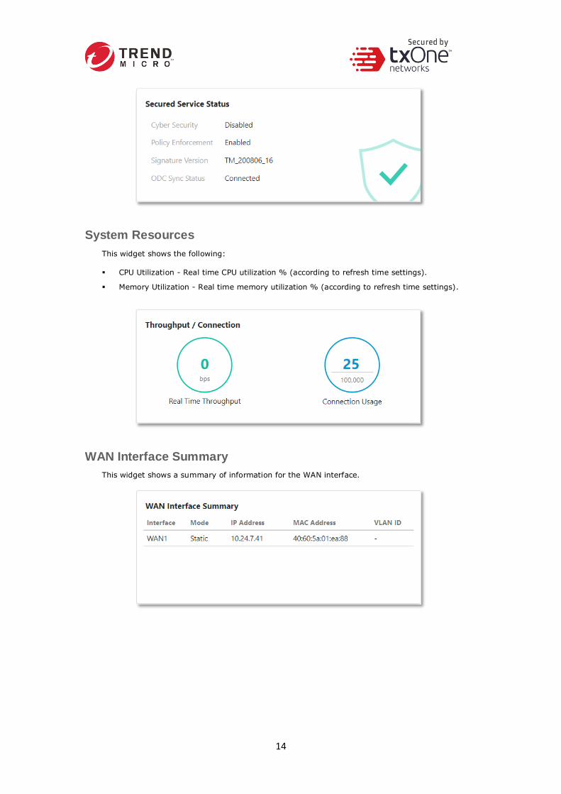
System Resources
This widget shows the following:
▪ CPU Utilization - Real time CPU utilization % (according to refresh time settings).
▪ Memory Utilization - Real time memory utilization % (according to refresh time settings).
WAN Interface Summary
This widget shows a summary of information for the WAN interface.
15
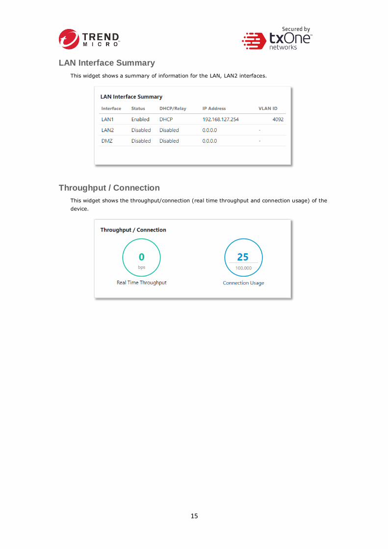
LAN Interface Summary
This widget shows a summary of information for the LAN, LAN2 interfaces.
Throughput / Connection
This widget shows the throughput/connection (real time throughput and connection usage) of the
device.

16
Chapter 4
The Visibility Tab
The [Visibility] tab gives you an overview of asset visibility for your managed assets. The tab
provides you with timely and accurate information on the assets that are managed by
EdgeFire™.
The assets, listed on the tab, are automatically detected by the EdgeFire™ device.
Note: The term asset in this chapter refers to the devices or hosts that are protected by the
EdgeFire.
Active Query
Active query can detect inactive or dormant assets or passive assets in the network.
Note: In firmware 1.1, Active query supports 4 protocols (Modbus, CIP, OMRON FINS and
SMB)
Viewing Asset Information
Procedure
1. Go to [Visibility] > [Assets View].
2. Click an asset icon to view its detailed information.

17
The [Assets Information] pane shows the following information for the asset:
Field Description
Vendor Name The vendor name of the asset.
Model Name The model name of the asset.
Asset Type The asset type of the asset.
Host Name The name of the asset.
Serial Number The serial number of the asset.
OS The operating system of the asset.
MAC Address The MAC address of the asset.
IP Address The IP address of the asset.
First Seen The date and time the asset was first seen.
Last Seen The date and time the asset was last seen.
Viewing Real Time Network Application Traffic
Procedure
1. Go to [Visibility] > [Assets View].
2. Click an asset icon and view its detailed information.
3. The [Real Time Network Application Traffic] pane shows a list of network traffic statistics for
the asset
Field Description
No. Ordinal number of the application traffic.
Application Name The application type of the traffic.
TX The amount of traffic transmitted for this traffic.
RX The amount of traffic received for this traffic.
Note: Click the [Manual asset info refresh] to refresh the information displayed.
Note: Specify the refresh time under the [Refresh Time] dropdown menu.
18
Chapter 5
The Network Tab
This chapter describes how to configure the physical ports and network interfaces for your
EdgeFire device.
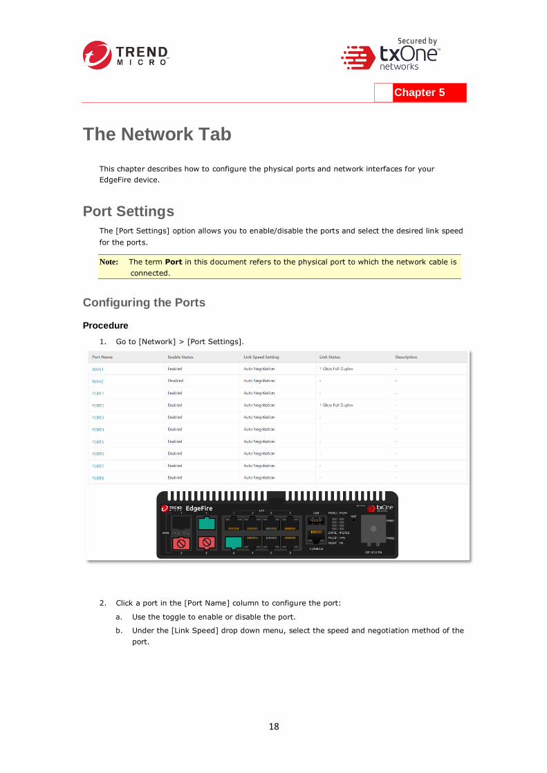
Port Settings
The [Port Settings] option allows you to enable/disable the ports and select the desired link speed
for the ports.
Note: The term Port in this document refers to the physical port to which the network cable is
connected.
Configuring the Ports
Procedure
1. Go to [Network] > [Port Settings].
2. Click a port in the [Port Name] column to configure the port:
a. Use the toggle to enable or disable the port.
b. Under the [Link Speed] drop down menu, select the speed and negotiation method of the
port.

19
Note: The pane picture on the tab shows a graphical depiction of the ports that are connected
on the device.
Note: Dual WAN is currently not supported. The WAN2 is disabled.
3. (Optional) Click the [Manual Port Refresh] button to refresh the information displayed.
Port Mapping
Use the [Port Mapping] tab to view the mappings between the ports and the interfaces.
Viewing the Port Mapping
Procedure
1. Go to [Network] > [Port Mapping].
2. The Port Mapping tab will appear. This tab shows mapping between the physical ports and
the interfaces (WAN interface or LAN interface).

20
Network Interface
Use the [Network Interface] tab to configure the following:
▪ Network settings of the network interfaces of the device
▪ DHCP settings on the LAN network interface, including:
▪ Disabling DHCP service
▪ Enabling DHCP service
▪ Configuring DHCP Relay
▪ Connection type for the WAN network interface, including:
▪ Static IP address settings
▪ DHCP client
Note: The term Network Interface or Interface in this document refers to the logical
interface that maps to one or more physical ports.
Note: The default web management console IP address is 192.168.127.254. The IP address
is bound to LAN1 network interface. To change the default IP address, see Configuring
LAN Network Interface on page 20.
Configuring LAN Network Interface
Procedure
1. Go to [Network] > [Network Interface].
The [Network Interface] tab will appear.
2. Click an LAN interface.
The [Edit Network Interface] tab will appear.

21
3. Use the toggle to enable or disable the network interface.
4. Input a descriptive name for the network interface.
5. In the [Network Setting] section, configure the network settings for the interface:
a. Input an IP address.
b. Input a subnet mask.
c. (Optional) Use the toggle to enable or disable VLAN ID. If VNLAN ID is enabled, input the
VLAN ID.
6. In the [DHCP] section, configure the DHCP settings for the interface. Possible choices are:
a. Disabled. No DHCP service will be provided at this interface.
b. DHCP Server. This interface will provide DHCP service to the devices that connect to the
interface. Once this is selected, you need to provide the following information:

22
▪ Start IP address of the DHCP service
▪ End IP address of the DHCP service
▪ Gateway IP address that will be assigned to the clients
▪ Lease time - The amount of time in seconds that a client device can use the IP
address settings assigned by the DHCP server
▪ DNS server IP addresses that will be assigned to the clients
c. DHCP Relay. This interface will relay the traffic from the clients to a relayed server for
DHCP service. Once this is selected, you need to provide the following information:
▪ Relay Server Address: The IP address of the server that will provide DHCP service
23
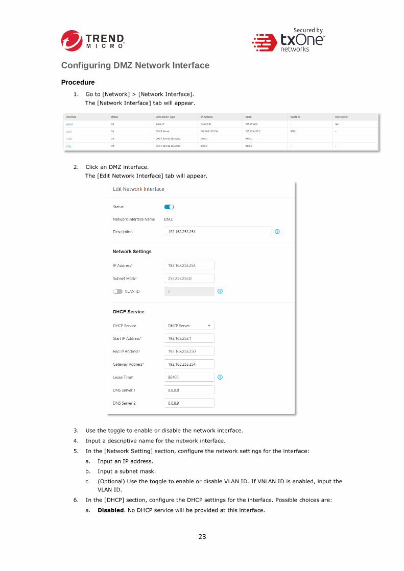
Configuring DMZ Network Interface
Procedure
1. Go to [Network] > [Network Interface].
The [Network Interface] tab will appear.
2. Click an DMZ interface.
The [Edit Network Interface] tab will appear.
3. Use the toggle to enable or disable the network interface.
4. Input a descriptive name for the network interface.
5. In the [Network Setting] section, configure the network settings for the interface:
a. Input an IP address.
b. Input a subnet mask.
c. (Optional) Use the toggle to enable or disable VLAN ID. If VNLAN ID is enabled, input the
VLAN ID.
6. In the [DHCP] section, configure the DHCP settings for the interface. Possible choices are:
a. Disabled. No DHCP service will be provided at this interface.

24
b. DHCP Server. This interface will provide DHCP service to the devices that connect to the
interface. Once this is selected, you need to provide the following information:
▪ Start IP address of the DHCP service
▪ End IP address of the DHCP service
▪ Gateway IP address that will be assigned to the clients
▪ Lease time - The amount of time in seconds that a client device can use the IP
address settings assigned by the DHCP server
▪ DNS server IP addresses that will be assigned to the clients
c. DHCP Relay. This interface will relay the traffic from the clients to a relayed server for
DHCP service. Once this is selected, you need to provide the following information:
▪ Relay Server Address: The IP address of the server that will provide DHCP service
Configuring WAN Network Interface
Procedure
1. Go to [Network] > [Network Interface].
The [Network Interface] tab will appear.

25
2. Click a WAN interface.
The [Edit Network Interface] tab will appear.
3. Use the toggle to enable or disable the network interface.
4. Input a descriptive name for the network interface.
5. In the [Network Settings] section, choose a [Connection Type] for the interface. Possible
choices are:
a. Static IP: This device will use a static IP address for this interface. Once selected, you
need to provide the following information:

26
▪ IP Address: IP address of the interface
▪ Subnet Mask: Subnet mask of the interface
▪ Gateway Address: Gateway IP address of the interface
▪ DNS server: DNS server IP address of the interface
▪ (Optional) Use the toggle to enable VLAN ID. Once enabled, input the VLAN ID for
the interface.
b. DHCP Client: The interface will function as a DHCP client to get an IP address from a
DHCP server. Once selected, you need to provide the following information:
▪ (Optional) Use the toggle to enable VLAN ID. Once enabled, input the VLAN ID for
the interface.

27
Operation Mode
EdgeFire™ offers two operation modes:
▪ Gateway Mode
▪ Bridge Mode
The following sections describe these two modes in detail.
Gateway Mode
EdgeFire operates as a gateway with NAT feature between multiple different network segments,
actively analyzing, filtering, and taking actions on all traffic that passes through it.
Bridge Mode
EdgeFire sits in the direct communication path between source and destination, actively
analyzing, filtering, and taking actions on all traffic that passes through it.

28
Use the [Operation Mode] tab to configure or view the following:
▪ Gateway mode and bridge mode of the device
▪ Network settings of bridge mode of the device (When the device is in Gateway mode)
▪ IP Address
▪ Subnet Mask
▪ Gateway Address
▪ DNS
▪ VLAN ID
▪ STP (Spanning Tree Protocol)
▪ LAN1 Network settings of gateway mode of the device
(When the device is in Bridge mode, it is for viewing only)
▪ IP Address
▪ Subnet Mask
▪ LAN1 DHCP service settings of gateway mode of the device
(When the device is in Bridge mode, it is for viewing only)
▪ DHCP Service
▪ Start IP Address
▪ End IP Address
▪ Gateway Address
▪ Lease Time
Switch from Gateway Mode to Bridge Mode
Procedure
1. Go to [Network] > [Operation Mode].
The [Operation Mode] tab will appear.
2. Click the radio button [Bridge Mode].
The [Network Settings] section for bridge mode will appear.

29
3. In the [Network Settings] section, configure the network settings for bridge mode:
a. Input an IP address.
b. Input a subnet mask.
c. Input a gateway address.
d. Input a DNS address.
e. (Optional) Use the toggle to enable or disable VLAN ID. If VNLAN ID is enabled, input the
VLAN ID.
f. (Optional) Use the toggle to enable or disable STP (Spanning Tree Protocol).
g. Click [Save] to save the settings.
4. Click [Save] to save the settings.
Note: When EdgeFire is switched from gateway mode to Bridge mode, the features of Port
Mapping, Network Interface, NAT Rules, ALG, and Static Route will not operate and not
be configurable.
Note: The configuration of the policy enforcement rule is not compatible between Gateway
mode and Bridge mode. Therefore, the policy enforcement rule needs to be
reconfigured after switching from Gateway mode to Bridge mode.
Switch from Bridge Mode to Gateway Mode
Procedure
1. Go to [Network] > [Operation Mode].
The [Operation Mode] tab will appear.

30
2. Click the radio button [Gateway Mode].
The [Network Settings] tab for bridge mode will appear.
3. Click [Save] to save the settings.
Note: In bridge mode, the LAN1 network settings / LAN1 DHCP Service for Gateway mode is
for viewing only.
Note: The configuration of the policy enforcement rule is not compatible between Gateway
mode and Bridge mode. Therefore, the policy enforcement rule needs to be
reconfigured after switching from Bridge mode to Gateway mode.

31
Chapter 6
The NAT Tab
Use the NAT (Network Address Translation) tab to view and configure NAT rules, and enable or
disable application layer gateways.
NAT Rule
Use the NAT tab to configure the following:
▪ 1 to 1 network address translation for incoming traffic on the specific interface
▪ Multiple 1 to 1 network address translation for incoming traffic on the specific interface
▪ Port forwarding address translation for incoming traffic on the specific interface
The following table describes the tasks you can perform on the [NAT Rule] tab.
Task Description
Add an NAT rule Click [Add] to create a new NAT rule.
Edit an NAT rule Click on an NAT rule name to edit the rule settings.
Delete an NAT rule Select one or more NAT rules and click [Delete].
Copy an NAT rule Select one NAT rule and click [Copy].
Configuring a 1 to 1 NAT Rule
A 1 to 1 NAT rule allows you to map a destination IP address in incoming traffic to another IP
address located in the specific network.
Procedure
1. Go to [NAT] > [NAT Rule].
The [NAT] tab will appear.
2. Do one of the following:
▪ Click [Add] to create an NAT rule.
▪ Click an NAT rule name to edit its settings.
3. Configuring an NAT rule:
a. Use the toggle to enable or disable the rule.
b. Under the [NAT Type] drop down menu, select [1 to 1 NAT].
c. Input a descriptive name for the rule.
d. Input a description for the rule.

32
e. Under the [Incoming Interface] drop-down menu, select the interface that will process
the incoming traffic for this rule.
f. In the [Original IP] field, input the destination IP address that will be translated. When
the device receives an incoming packet going through the interface specified in the
[Incoming Interface], the destination IP address in the packet that matches this [Original
IP] field will be mapped another IP address.
g. In the [Mapped IP] field, input the IP address you will map to. This IP address is usually
a private IP address in your local network.
h. (Optional) Use the toggle to enable NAT loopback.
4. Click [OK] to accept the rule.
5. Click [Save] to save the settings.
Note: Starting from firmware 1.1, [Network Interface] now can support WAN1, LAN1, LAN2
and DMZ interface when [NAT Type] is selected to “1 to 1 NAT”.
Configuring a Multiple 1 to 1 NAT Rule
A multiple 1 to 1 NAT rule allows you to map destination IP addresses in incoming traffic to
different IP addresses located in the specific network. The following table shows an example.
Original Destination IP Addresses … Are Mapped to These Destination IP Addresses
172.1.1.5 192.168.100.5
172.1.1.20 192.168.100.20
172.1.1.50 192.168.100.50
172.1.1.69 192.168.100.69
Procedure
1. Go to [NAT] > [NAT Rule].

33
The [NAT] tab will appear.
2. Do one of the following:
▪ Click [Add] to create an NAT rule.
▪ Click an NAT rule name to edit its settings.
3. Configuring the NAT rule:
a. Use the toggle to enable or disable the rule.
b. Under the [NAT Type] drop-down menu, select [Multi 1 to 1 NAT].
c. Input a descriptive name for the rule.
d. Input a description for the rule.
e. Under the [Incoming Interface] drop-down menu, select the interface that will process
the incoming traffic for this rule.
f. In the [Original IP] fields, input using the CIDR (Classless Inter-Domain Routing) format
to present the IP addresses that will be translated; for example, 172.1.1.0 / 24. When
the device receives an incoming packet going through the interface specified in the
[Incoming Interface], the destination IP address in the packet that matches this [Original
IP] field will be mapped to another IP address. These IP addresses are usually the ones
assigned by an ISP (Internet Service Provider).
g. In the [Mapped IP] field, input using the CIDR (Classless Inter-Domain Routing) format
to present the IP addresses that will be mapped to; for example, 192.168.100.0 / 24
h. (Optional) Use the toggle to enable NAT loopback.
4. Click [OK] to accept the rule.
5. Click [Save] to save the settings.

34
Note: Starting from firmware 1.1, [Network Interface] now can support WAN1, LAN1, LAN2
and DMZ interface when [NAT Type] is selected to “Multi 1 to 1 NAT”.
Configuring Port Forwarding
A port forwarding rule allows you to map a host IP address in incoming traffic to another IP
address located in your local network.
Procedure
1. Go to [NAT] > [NAT Rule].
The [NAT] tab will appear.
2. Do one of the following:
▪ Click [Add] to create an NAT rule.
▪ Click an NAT rule name to edit its settings.
3. Configuring an NAT rule:
a. Use the toggle to enable or disable the rule.
b. Under the [NAT Type] drop down menu, select [Port Forward].
c. Input a descriptive name for the rule.
d. Input a description for the rule.
e. Under the [Incoming Interface] drop-down menu, select the interface that will process
the incoming traffic for this rule.
f. Under the [Protocol] drop-down menu, select the protocol that will process the incoming
traffic for this rule.
g. In the [Original IP] field, input the start port and the end port that will be translated.
When the device receives an incoming packet going through the interface specified in the
[Incoming Interface], the destination IP address in the packet that matches this [Original
IP] field will be mapped another IP and port address.
h. In the [Mapped IP] field, input the IP address and port range you will map to. This IP
address is usually a private IP address in your local network.
i. (Optional) Use the toggle to enable NAT loopback.

35
4. Click [OK] to accept the rule.
5. Click [Save] to save the settings.
ALG An ALG or Application Layer Gateway allows client applications to communicate with server
applications when the server ports are dynamically opened to client applications. These ports are
usually dynamically assigned in the application protocol. An ALG understands application
protocols, recognizes application specific commands, and helps open the ports dynamically on the
device for communication. Without ALG, client applications like FTP would not be able to transfer
files when the FTP client is in an NAT network.
Use the ALG (Application Layer Gateway) tab to configure the following:
▪ FTP ALG
▪ SIP ALG
▪ H.323 ALG
Configuring ALG Settings
Procedure
1. Go to [NAT] > [ALG].
The [ALG Settings] tab will appear.
2. Use the toggle to enable or disable FTP, SIP and H.323 ALG.
3. Click [Save].

36

37
Chapter 7
The Routing Tab
Use the [Routing] tab to view and configure static routes on the device.
Static Route
Static routes are generally used when no appropriate dynamic route is present, or when you want
the traffic to follow the static route you specify as opposed to following the dynamic route that is
automatically learned and generated by the device.
Use the [Static Route] tab to view a list of current static routes on the device and configure their
settings.
The following table describes the tasks you can perform on the [Static Route] tab.
Task Description
Add a static route Click [Add] to create a new static route.
Edit a static route Click a static route name to edit the rule settings.
Delete a static route Select one or more static routes and click [Delete].
Copy a static route Select one static route and click [Copy].
Configuring a Static Route
Procedure
1. Go to [Routing] > [Static Route].
2. Do one of the following:
▪ Click [Add] to create a static route.
▪ Click a static route name to edit settings.
3. Configuring the static route:
a. Use the toggle to enable or disable the route.
b. Input a descriptive name for the rule.
c. Input a description for the rule.
d. Configure the destination:
▪ In the [Destination Address] field, input IP address.
▪ In the [Subnet Mask] field, input the subnet mask.
Tip: If the destination is a single IP address, then input 255.255.255.255 in the [Subnet
Mask] field. If the destination is a subnet of IP addresses, then input, for example,
255.255.255.0, in the [Subnet Mask] to present the destination IP address range.
e. Configure the next hop:
▪ If the next hop is a gateway, then under [Next Hop Type], select [Gateway IP
Address] and input the IP address. The gateway needs to be on the same network
as the interface.
▪ If the next hop is a network interface on the device, then under [Next Hop Type],
select [Network Interface], and select a network interface from the drop-down

38
menu. [Note] For this firmware of the device, the available network interface to be
selected is fixed to [WAN 1].
Tip: For more information about network interface, see Network Interface on page 18.
f. Input the metric value:
▪ In the [Metric] field, input a metric value for this static route. The device determines
which static route to use based on the metric value, with the lower number
representing higher priority.
g. Click [OK] to accept the settings.
h. Click [Save] to save the rule.

39
Chapter 8
The Object Profiles Tab
Object profiles simplify policy management by storing configurations that can be used by
EdgeFire™.
You can configure the following types of object profiles in this device:
▪ IP Object Profile: Contains the IP addresses that you can apply to a policy rule.
▪ Service Object Profile: Contains the service definitions that you can apply to a policy rule.
TCP port range, UDP port range, ICMP, and custom protocol number are defined here.
▪ Protocol Filter Profile: Contains more sophisticated and advanced protocol settings that
you can apply to a policy rule. Details of ICS (Industrial Control System) protocols are
defined here.
The following table describes the tasks you can perform when you view a list of the profiles:
Task Description
Add a profile Click [Add] to create a new profile.
Edit a profile Click a profile name to edit the settings.
Delete a profile Select one or more profiles and click [Delete].
Copy a profile Select one profile and click [Copy].
Configuring IP Object Profile
You can configure the IP address in an IP object profile, which can be used by other policy rules.
The types of IP address you can assign are:
▪ Single IP addresses
▪ IP ranges
▪ IP subnets
Procedure
1. Go to [Object Profile] > [IP Object Profile].
2. Do one of the following:
▪ Click [Add] to create a profile.
▪ Click a profile name to edit settings.
3. Type a descriptive name for the IP Object Name field.

40
4. Type a description.
5. Under the [IP Object List], specify an IP address, an IP range, or an IP subnet.
6. If you want to add another entry, click the button.
7. Click [OK].
Configuring Service Object Profile
In a service object profile, you can define the following:
▪ TCP protocol port range
▪ UDP protocol port range
▪ ICMP protocol type and code
▪ Custom protocol with specified protocol number
Note: The term ‘protocol number’ refers to the protocol number defined in the internet
protocol suite.
Procedure
1. Go to [Object Profile] > [Service Object Profile].
2. Do one of the following:
▪ Click [Add] to create a profile.
▪ Click a profile name to edit settings.
3. Type a descriptive name for the Service Object Profile.
4. Type a description.
5. Provide one of the following definitions:
• TCP protocol and its port range
• UDP protocol and its port range
• ICMP protocol and its type and code
• Custom protocol with specified protocol number
6. If you want to add another entry, click the button.
7. Click [OK].

41
Configuring Protocol Filter Profile
A protocol filter profile contains more sophisticated and advanced protocol settings that you can
apply to a policy rule.
The following can be configured in a protocol filter profile:
▪ Details of ICS protocols, including:
▪ Modbus
▪ CIP
▪ S7COMM
▪ S7COMM PLUS
▪ PROFINET
▪ SLMP
▪ MELSOFT
▪ FINS
▪ SECS/GEM
▪ TOYOPUC
▪ IEC61850-MMS
▪ General Protocol, including:
▪ HTTP
▪ FTP
▪ SMB
▪ RDP
▪ MQTT

42
Specifying Commands Allowed in an ICS Protocol
When configuring an ICS protocol, you can specify which commands will be included in the
protocol profile, as the following picture shows.
Applying the Drop Malformed Option to an ICS Protocol
When configuring an ICS protocol, you can specify which OT protocols will be applied with the
option [Drop Malformed] in the protocol profile, as the following picture shows.
When the option [Drop Malformed] is enabled, EdgeFire will strictly check the packet format of
the specified ICS protocol. If the packet format is incorrect, EdgeFire will drop the packets of the
ICS protocol.
Note: In firmware 1.1, Drop Malformed supports 4 protocols (Modbus, CIP, OMRON FINS and
TOYOPUC)

43
Advanced Settings for Modbus Protocol
The device features more detailed configurations for the Modbus ICS protocol. Through the
[Advanced Settings] pane, you can further specify the function code/function, unit ID, and
address/addresses range against which the function will operate.
Procedure
1. Go to [Object Profile] > [Protocol Filter Profile].
2. Click [Add] to add a protocol filter profile.
The [Create Protocol Filter Profile] screen will appear.
3. Type a profile name for the protocol filter.
4. Type a description.

44
5. In the [ICS Protocol] pane, select the protocols you want to include in the protocol filter.
• Click [Settings] next to a protocol, and select one of the following:
▪ Any - Specify all available commands or function access in this protocol.
▪ Basic - Multiple selections of the following:
▪ Read Only: Read commands sent from HMI (Human-Machine Interface) /
EWS (Engineering Work Station) / SCADA (Supervisory Control and Data
Acquisition) to PLC (Programmable Logic Controller).
▪ Read / Write: Read and write commands sent from HMI/EWS/SCADA to PLC.
▪ Admin Config: Firmware update commands sent from EWS to PLC, Project
update (i.e., PLC code download) commands sent from EWS to PLC, and
administration configuration relevant commands sent from EWS to PLC.
▪ Others: Private commands, un-documented commands, or particular
protocols provided by an ICS vendor.
• If you have selected [Modbus], you can optionally configure advanced settings for this
protocol:
▪ Click [Settings] next to [Modbus], and select [Advanced Matching Criteria].
▪ At the [Function list] drop down menu, select a function of this protocol.
▪ If you want to specify a function code by yourself, then select [Custom] and input a
function code in the [Function Code] field.
▪ Type a unit ID in the [Unit ID] field.
▪ Type the address or range of addresses against which the function will operate.
▪ Click [Add].
▪ Repeat the above steps if you want to add more protocol definition entries.
▪ Click [OK].
6. In the [General Protocol] pane, select the protocols you want to include in the protocol filter.
7. Click [OK].

45
Advanced Settings for CIP Protocol
The device features more detailed configurations for the CIP ICS protocol. Through the [Advanced
Settings] pane, you can further specify the Object Class ID, and Service Code against which the
function will operate.
Procedure
1. Go to [Object Profile] > [Protocol Filter Profile].
2. Click [Add] to add a protocol filter profile.
The [Create Protocol Filter Profile] screen will appear.

46
3. Type a profile name for the protocol filter.
4. Type a description.
5. In the [ICS Protocol] pane, select the protocols you want to include in the protocol filter.
• Click [Settings] next to a protocol, and select one of the following:
▪ Any - Specify all available commands or function access in this protocol.
▪ Basic - Multiple selections of the following:
▪ Read Only: Read commands sent from HMI (Human-Machine Interface) /
EWS (Engineering Work Station) / SCADA (Supervisory Control and Data
Acquisition) to PLC (Programmable Logic Controller).
▪ Read / Write: Read and write commands sent from HMI/EWS/SCADA to PLC.
▪ Admin Config: Firmware update commands sent from EWS to PLC, Project
update (i.e., PLC code download) commands sent from EWS to PLC, and
administration configuration relevant commands sent from EWS to PLC.
▪ Others: Private commands, un-documented commands, or particular
protocols provided by an ICS vendor.
• If you have selected [CIP], you can optionally configure advanced settings for this protocol:

47
▪ Click [Settings] next to [CIP], and select [Advanced Matching Criteria].
▪ At the [Object Class List] drop down menu, select a function of this protocol.
▪ If you want to all the service codes within the function you specified to be applied,
then select [Any Service Code]
▪ If you want to specify one service code or multiple service codes, then select [Preset
Service Code] and move the service code(s) from the [Available Service Code] field
to the [Selected Service Code] field.
▪ If you want to specify a service code by yourself, then select [Custom Service Code]
and input a service code in the [Custom Service Code] field.
▪ Click [Add].
▪ Repeat the above steps if you want to add more protocol definition entries.
▪ Click [OK].
6. In the [General Protocol] pane, select the protocols you want to include in the protocol filter.
7. Click [OK].

48
Advanced Settings for S7Comm
The device features more detailed configurations for the S7Comm ICS protocol. Through the
[Advanced Settings] pane, you can further specify the function code, function group code, and
sub-function code against which the function will operate.
Procedure
1. Go to [Object Profile] > [Protocol Filter Profile].
2. Click [Add] to add a protocol filter profile.
The [Create Protocol Filter Profile] screen will appear.

49
3. Type a profile name for the protocol filter.
4. Type a description.
5. In the [ICS Protocol] pane, select the protocols you want to include in the protocol filter.
• Click [Settings] next to a protocol, and select one of the following:
▪ Any - Specify all available commands or function access in this protocol.
▪ Basic - Multiple selections of the following:
▪ Read Only: Read commands sent from HMI (Human-Machine Interface) /
EWS (Engineering Work Station) / SCADA (Supervisory Control and Data
Acquisition) to PLC (Programmable Logic Controller).
▪ Read / Write: Read and write commands sent from HMI/EWS/SCADA to PLC.
▪ Admin Config: Firmware update commands sent from EWS to PLC, Project
update (i.e., PLC code download) commands sent from EWS to PLC, and
administration configuration relevant commands sent from EWS to PLC.
▪ Others: Private commands, un-documented commands, or particular
protocols provided by an ICS vendor.
• If you have selected [S7Comm], you can optionally configure advanced settings for this
protocol:

50
▪ Click [Settings] next to [S7Comm], and select [Advanced Matching Criteria].
▪ If you want to specify one function code from the category [Job], then select the
category [Job] and select a function at the [Function list] drop down menu.
▪ If you want to specify one function group code from the category [Userdata], then
select the category [Userdata] and select a function group code at the [Function
Group Code] drop down menu.
o If you want to all the sub-function codes within the function group code you
specified to be applied, then select [Any Sub-function Code]
o If you want to specify one sub-function code or multiple sub-function
codes, then select [Preset Sub-function Code] and move the sub-function

51
code(s) from the [Available Sub-function Code] to the [Selected Sub-
function Code] field.
o If you want to specify a service code by yourself, then select [Custom Sub-
function Code] and input a sub-function code in the [Custom Sub-function
Code] field.
▪ Click [Add].
▪ Repeat the above steps if you want to add more protocol definition entries.
▪ Click [OK].
6. In the [General Protocol] pane, select the protocols you want to include in the protocol filter.
7. Click [OK].
Advanced Settings for S7Comm Plus
The device features more detailed configurations for the S7Comm Plus ICS protocol. Through the
[Advanced Settings] pane, you can further specify the function code against which the function
will operate.
Procedure
1. Go to [Object Profile] > [Protocol Filter Profile].
2. Click [Add] to add a protocol filter profile.
The [Create Protocol Filter Profile] screen will appear.

52
3. Type a profile name for the protocol filter.
4. Type a description.
5. In the [ICS Protocol] pane, select the protocols you want to include in the protocol filter.
• Click [Settings] next to a protocol, and select one of the following:
▪ Any - Specify all available commands or function access in this protocol.
▪ Basic - Multiple selections of the following:
▪ Read Only: Read commands sent from HMI (Human-Machine Interface) /
EWS (Engineering Work Station) / SCADA (Supervisory Control and Data
Acquisition) to PLC (Programmable Logic Controller).
▪ Read / Write: Read and write commands sent from HMI/EWS/SCADA to PLC.
▪ Admin Config: Firmware update commands sent from EWS to PLC, Project
update (i.e., PLC code download) commands sent from EWS to PLC, and
administration configuration relevant commands sent from EWS to PLC.
▪ Others: Private commands, un-documented commands, or particular
protocols provided by an ICS vendor.
• If you have selected [S7Comm Plus], you can optionally configure advanced settings for this
protocol:

53
▪ Click [Settings] next to [S7Comm Plus], and select [Advanced Matching Criteria].
▪ At the [Function list] drop down menu, select a function of this protocol.
▪ Click [Add].
▪ Repeat the above steps if you want to add more protocol definition entries.
▪ Click [OK].
6. In the [General Protocol] pane, select the protocols you want to include in the protocol filter.
7. Click [OK].

54
Advanced Settings for SLMP
The device features more detailed configurations for the SLMP ICS protocol. Through the
[Advanced Settings] pane, you can further specify the command code against which the function
will operate.
Procedure
1. Go to [Object Profile] > [Protocol Filter Profile].
2. Click [Add] to add a protocol filter profile.
The [Create Protocol Filter Profile] screen will appear.

55
3. Type a profile name for the protocol filter.
4. Type a description.
5. In the [ICS Protocol] pane, select the protocols you want to include in the protocol filter.
• Click [Settings] next to a protocol, and select one of the following:
▪ Any - Specify all available commands or function access in this protocol.
▪ Basic - Multiple selections of the following:
▪ Read Only: Read commands sent from HMI (Human-Machine Interface) /
EWS (Engineering Work Station) / SCADA (Supervisory Control and Data
Acquisition) to PLC (Programmable Logic Controller).
▪ Read / Write: Read and write commands sent from HMI/EWS/SCADA to PLC.
▪ Admin Config: Firmware update commands sent from EWS to PLC, Project
update (i.e., PLC code download) commands sent from EWS to PLC, and
administration configuration relevant commands sent from EWS to PLC.
▪ Others: Private commands, un-documented commands, or particular
protocols provided by an ICS vendor.
• If you have selected [SLMP], you can optionally configure advanced settings for this protocol:

56
▪ Click [Settings] next to [SLMP], and select [Advanced Matching Criteria].
▪ At the [Command Code List] drop down menu, select a function of this protocol.
▪ Click [Add].
▪ Repeat the above steps if you want to add more protocol definition entries.
▪ Click [OK].
6. In the [General Protocol] pane, select the protocols you want to include in the protocol filter.
7. Click [OK].

57
Advanced Settings for MELSOFT
The device features more detailed configurations for the MELSOFT ICS protocol. Through the
[Advanced Settings] pane, you can further specify the command code against which the function
will operate.
Procedure
1. Go to [Object Profile] > [Protocol Filter Profile].
2. Click [Add] to add a protocol filter profile.
The [Create Protocol Filter Profile] screen will appear.

58
3. Type a profile name for the protocol filter.
4. Type a description.
5. In the [ICS Protocol] pane, select the protocols you want to include in the protocol filter.
• Click [Settings] next to a protocol, and select one of the following:
▪ Any - Specify all available commands or function access in this protocol.
▪ Basic - Multiple selections of the following:
▪ Read Only: Read commands sent from HMI (Human-Machine Interface) /
EWS (Engineering Work Station) / SCADA (Supervisory Control and Data
Acquisition) to PLC (Programmable Logic Controller).
▪ Read / Write: Read and write commands sent from HMI/EWS/SCADA to PLC.
▪ Admin Config: Firmware update commands sent from EWS to PLC, Project
update (i.e., PLC code download) commands sent from EWS to PLC, and
administration configuration relevant commands sent from EWS to PLC.
▪ Others: Private commands, un-documented commands, or particular
protocols provided by an ICS vendor.
• If you have selected [MELSOFT], you can optionally configure advanced settings for this
protocol:

59
▪ Click [Settings] next to [MELSOFT], and select [Advanced Matching Criteria].
▪ At the [Command Code List] drop down menu, select a function of this protocol.
▪ Click [Add].
▪ Repeat the above steps if you want to add more protocol definition entries.
▪ Click [OK].
6. In the [General Protocol] pane, select the protocols you want to include in the protocol filter.
7. Click [OK].

60
Advanced Settings for TOYOPUC
The device features more detailed configurations for the TOYOPUC ICS protocol. Through the
[Advanced Settings] pane, you can further specify the command code, preset sub-command code
and custom sub-command code against which the function will operate.
Procedure
1. Go to [Object Profile] > [Protocol Filter Profile].
2. Click [Add] to add a protocol filter profile.
The [Create Protocol Filter Profile] screen will appear.

61
3. Type a profile name for the protocol filter.
4. Type a description.
5. In the [ICS Protocol] pane, select the protocols you want to include in the protocol filter.
• Click [Settings] next to a protocol, and select one of the following:
▪ Any - Specify all available commands or function access in this protocol.
▪ Basic - Multiple selections of the following:
▪ Read Only: Read commands sent from HMI (Human-Machine Interface) /
EWS (Engineering Work Station) / SCADA (Supervisory Control and Data
Acquisition) to PLC (Programmable Logic Controller).
▪ Read / Write: Read and write commands sent from HMI/EWS/SCADA to PLC.
▪ Admin Config: Firmware update commands sent from EWS to PLC, Project
update (i.e., PLC code download) commands sent from EWS to PLC, and
administration configuration relevant commands sent from EWS to PLC.
▪ Others: Private commands, un-documented commands, or particular
protocols provided by an ICS vendor.
• If you have selected [TOYOPUC], you can optionally configure advanced settings for this
protocol:
▪ Click [Settings] next to [TOYOPUC], and select [Advanced Matching Criteria].
▪ At the [Command Code List] drop down menu, select a function of this protocol.

62
▪ If you want to specify one sub-command code or multiple sub-command codes, then
select [Preset Sub-cmd Code] and move the sub-function code(s) from the
[Available Sub-cmd Code] field to the [Selected Sub-cmd Code] field.
▪ If you want to specify a sub-command code by yourself, then select [Custom Sub-
cmd Code] and input a sub-command code in the [Custom Sub-cmd Code] field.
▪ Click [Add].
▪ Repeat the above steps if you want to add more protocol definition entries.
▪ Click [OK].
Note: Not all the command codes support the feature of [Preset Sub-cmd code] and [Custom
Sub-cmd]. Only the command code “(0x32) Function Call” and “(0xA0) Expansion
Function Call” support them.

63
6. In the [General Protocol] pane, select the protocols you want to include in the protocol filter.
7. Click [OK].
Configuring IPS Profile An IPS profile contains more sophisticated pattern rules that you can do granular control and
apply to a policy rule.
The following can be configured in an IPS profile:
▪ Details of IPS protocol category, including:
▪ File Vulnerabilities
▪ Buffer Overflow
▪ Exploits
▪ Malware Traffic
▪ Reconnaissance
▪ Web Threats
▪ ICS Threats
▪ Others
▪ Details of IPS protocol risk level category, including:
▪ Information
▪ Medium
▪ High
▪ Critical
▪ Details of default action list for IPS patterns, including:
▪ All Actions
▪ Accept and Log
▪ Deny and Log

64
Configuring a Pattern Rule for Granular Control
When configuring an IPS pattern rule protocol, you can specify which action should be taken and
add it in the IPS profile, as the following picture shows.
Procedure
1. Go to [Object Profile] > [IPS Profile].
2. Click [Add] to add a IPS profile.
The [Create Protocol Filter Profile] screen will appear.

65
3. Type a profile name for the IPS profile.
4. Type a description.
5. Select a pattern rule you want to configure by clicking on the rule ID.
6. IPS rule details will show up. Select one of the following:
▪ Status - Specify the pattern rule to be enabled or disabled.
▪ Actions - Multiple selections of the following:
▪ Accept and Log: When the attack is detected by EdgeFire, the attack will be
bypassed and logged for monitoring.
▪ Deny and Log: When the attack is detected by EdgeFire, the attack will be
blocked and logged for monitoring.
Field Description
Status The operational status of the pattern rule
ID The pattern rule ID
Name The pattern name for the cyber attack
Category The threat category for the cyber attack
Risk Level The suggested security level for the cyber attack
Impact The damage that will cause to the target network device
if the cyber attack succeeds.
Reference The vulnerability ID of the cyber attacks
(e.g. CVE-2017-0147)
Actions The preset action for the cyber attacks.
keyword The word(s) for searching the pattern rules
7. If you already configure the pattern rule, press [Save].

66
Chapter 9
The Security Tab
This chapter describes the following configurations:
▪ Cyber security configuration, which allows you to define both intrusion prevention and
denial of service attack prevention settings.
▪ Policy enforcement configuration, which allows you to define a custom protocol that
matches to an industrial protocol, and then white-list or black-list these protocols in your
network environment.
Cyber Security This device features cyber security, which denial of service attack prevention. The signature rules
of intrusion prevention are called the ‘Trend Micro DPI (Deep Packet Inspection) Pattern’. This
pattern is provided by Trend Micro and can be regularly updated through ODC as well as through
manual import on web management UI of the device.
Configuring Cyber Security – Denial of Service Prevention
Procedure
1. Go to [Security] > [Cyber Security]
2. At the [Cyber Security] tab you will see the [Denial of Service Prevention] pane.
3. Use the toggle to enable or disable the denial of service prevention feature.
4. Select an action ([Monitor and Log] or [Prevent and Log]) for the feature.
5. You can optionally configure the thresholds of the denial of service rules.
Note: Flood/Scan Attack Protection rules utilize the detection period and threshold
mechanisms to detect an attack. During a detection period (typically every 5 seconds),
if the number of anomalous packets reaches the specified threshold, an attack detection
occurs. If the rule action is ‘block’, the security node blocks subsequent anomalous
packets until the end of the detection period. After the detection period, the security
node allows anomalous packets until the threshold is reached again.

67
6. Click [Save].
Policy Enforcement
Policy enforcement allows you to define a custom protocol that matches to an industrial protocol,
and then white-list or black-list such protocols in your network environment.
Configuring Policy Enforcement
Procedure
1. Go to [Security] > [Policy Enforcement]
2. At the [Policy Enforcement] tab you will see the [Policy Enforcement General Settings] pane
3. Use the toggle to enable or disable the policy enforcement feature.
4. Select a mode ([Monitor Mode], or [Prevention Mode]) for the policy enforcement.
5. Under the [Policy Enforcement Default Rule Action] drop down menu, select a default action
when no pattern is matched.
The following table summarizes the settings:
Mode
(Policy Enforcement)
Action Performed
Monitor Mode ▪ Detects and monitors protocol access to OT assets, but
does not block network attacks.
▪ Generates logs.
Prevention Mode ▪ Blocks abnormal protocol access to OT assets.
▪ Generates logs.
Adding Policy Enforcement Rules (In Gateway Mode)
Procedure
1. Configure the required object or objects.
▪ IP object profiles
For more information, see Configuring IP Object Profile.
▪ Service object profiles
For more information, see Configuring Service Object Profile.
▪ Protocol filter profiles
For more information, see Configuring Protocol Filter Profile.
▪ IPS profiles
For more information, see Configuring Protocol Filter Profile.

68
2. Go to [Security] > [Policy Enforcement]
3. Under the [Policy Enforcement] tab you will see the following pane.
4. Click the [Add] button to add a new policy rule.
5. Use the toggle to enable or disable the policy rule.
6. Input a descriptive name for the rule.
7. Input a description for the rule.
8. Under the [Interface Direction] drop-down menu, select one of the following for the network
traffic direction:
• Any
• WAN to LAN
• LAN to WAN
• WAN to DMZ
• DMZ to WAN
• LAN to DMZ
• DMZ to LAN
• LAN to LAN
Note: The network interface in the drop-down menu does not specify which exact network
interface, but two or more network interfaces of a kind from the broad view. For example, if you
select [WAN to LAN], then the policy enforcement rule will be effective on the traffic from WAN1
interface to LAN1 interface or WAN1 interface to LAN2 interface. If you select [LAN to LAN], then
the policy enforcement rule will be effective on the traffic from LAN1 interface to LAN2 interface
or LAN2 interface to LAN1 interface.
69
Note: If you select [Any], then the policy enforcement rule will be effective on the traffic from
all network interfaces.
9. Under the [Source IP / IP Object Profile] drop-down menu, select one of the following for the
source IP address(es):
• Any
• Single IP
• IP Range
• IP Subnet
• IP Object
Note: If you select [IP Object], then you need to select the IP object from an IP object profiles
that have been created beforehand.
10. Under the [Destination IP / IP Object Profile] drop-down menu, select either one of the
following for the destination IP address(es):
• Any
• Single IP
• IP Range
• IP Subnet
• IP Object
11. Under the [Service Object] drop-down menu, select one of the following for the layer 4
criteria:
▪ TCP
You can further specify the port range for this protocol.
▪ UDP
You can further specify the port range for this protocol.
▪ ICMP
You can further specify the type and code for this protocol.
▪ Custom
You can further specify the protocol number for this protocol. The term protocol number
refers to the one defined in the internet protocol suite.
▪ Service Object
Note: You need to select the service object from service object profiles that have been created
beforehand.
10. Under the [Action] drop-down menu, select one of the following:
• Accept: Select this option to allow network traffic that matches this rule.
• Deny: Select this option to block network traffic that matches this rule.
• Advanced Filter: The node will further take actions based on the protocol filter or the
IPS profile:
▪ Under the [Protocol Filter Profile] drop-down menu, select a protocol filter profile you
have defined beforehand.
▪ Under the [Protocol Filter Action] drop-down menu, select whether to allow or deny
network traffic that matches the protocol filter.

70
12. Click [OK] to save the configurations.
Note: The policy enforcement rule in gateway mode is effective on the level of network
interface only, not on the level of network physical port. The policy enforcement rule
cannot inspect the traffic between the physical ports under the same network interface.
The following table lists the common tasks that are used to manage the policy enforcement rules.
Task Action
To delete a policy enforcement
rule
Click the check box in front of the policy enforcement
rule and click the [Delete] button.
To duplicate a policy
enforcement rule
Click the check box in front of the policy enforcement
rule and click the [Copy] button.
To edit a policy enforcement
rule
Click the name of the rule, and an [Edit Policy Rule]
window will appear.
To change the priority of a
policy enforcement rule
Click the check box in front of the policy enforcement
rule, click the [Change Priority] button, and specify a
new priority for this rule.
Note: When more than one policy enforcement rule is matched, the device takes the action of
the rule with the highest priority, and ignores the rest of the rules. The rules are listed
on the table under the UI tab by priority, starting with the highest priority rule at the
top.
Adding Policy Enforcement Rules (In Bridge Mode)
Procedure
1. Configure the required object or objects.
▪ IP object profiles
For more information, see Configuring IP Object Profile.
▪ Service object profiles
For more information, see Configuring Service Object Profile.
▪ Protocol filter profiles
For more information, see Configuring Protocol Filter Profile.
▪ IPS profiles
For more information, see Configuring Protocol Filter Profile.
2. Go to [Security] > [Policy Enforcement]
3. Under the [Policy Enforcement] tab you will see the following pane.

71
4. Click the [Add] button to add a new policy rule.
5. Use the toggle to enable or disable the policy rule.
6. Input a descriptive name for the rule.
7. Input a description for the rule.
8. Under the [Source IP / IP Object Profile] drop-down menu, select one of the following for the
source IP address(es):
• Any
• Single IP
• IP Range
• IP Subnet
• IP Object
Note: If you select [IP Object], then you need to select the IP object from an IP object profiles
that have been created beforehand.
9. Under the [Destination IP / IP Object Profile] drop-down menu, select either one of the
following for the destination IP address(es):
• Any
• Single IP
• IP Range
• IP Subnet
• IP Object
10. Under the [Service Object] drop-down menu, select one of the following for the layer 4
criteria:
▪ TCP
You can further specify the port range for this protocol.
▪ UDP
You can further specify the port range for this protocol.

72
▪ ICMP
You can further specify the type and code for this protocol.
▪ Custom
You can further specify the protocol number for this protocol. The term protocol number
refers to the one defined in the internet protocol suite.
▪ Service Object
Note: You need to select the service object from service object profiles that have been created
beforehand.
11. Use the toggle to enable or disable the VLAN ID, then input one or multiple VLAN ID.
Note: You can input up to 5 VLAN IDs in one policy enforcement rule.
12. Under the [Action] drop-down menu, select one of the following:
• Accept: Select this option to allow network traffic that matches this rule.
• Deny: Select this option to block network traffic that matches this rule.
• Advanced Filter: The node will further take actions based on the protocol filter or the
IPS profile:
▪ Under the [Protocol Filter Profile] drop-down menu, select a protocol filter profile you
have defined beforehand.
▪ Under the [Protocol Filter Action], select whether to allow or deny network traffic
that matches the protocol filter.
13. Click [Save] to save the configurations.
Managing Policy Enforcement Rules
The following table lists the common tasks that are used to manage the policy enforcement rules.
Task Action
To delete a policy enforcement
rule
Click the check box in front of the policy enforcement
rule and click the [Delete] button.
To duplicate a policy
enforcement rule
Click the check box in front of the policy enforcement
rule and click the [Copy] button.
To edit a policy enforcement
rule
Click the name of the rule, and an [Edit Policy Rule]
window will appear.
To change the priority of a
policy enforcement rule
Click the check box in front of the policy enforcement
rule, click the [Change Priority] button, and specify a
new priority for this rule.
Note: When more than one policy enforcement rule is matched, the device takes the action of
the rule with the highest priority, and ignores the rest of the rules. The rules are listed

73
on the table under the UI tab by priority, starting with the highest priority rule at the
top.

74
Chapter 10
The Pattern Tab
This chapter describes how to view the pattern information and how to import a DPI (Deep Packet
Inspection) pattern to the EdgeFire™ device.
The DPI pattern, prepared by Trend Micro, contains signatures to enable the intrusion prevention
features on the device. The intrusion prevention features detect and prevent behaviors related to
network intrusion attempts or targeted attacks at the network level.
Viewing Device Pattern Information
Procedure
1. Go to [Pattern] > [Pattern Update]
2. Under the [Pattern Update] tab you will see the following pane.
3. The [Device Pattern Information] pane shows the [Current Pattern Version] and [Pattern
Build Date]
Manually Updating the Pattern
Procedure
1. Go to [Pattern] > [Pattern Update]
2. Under the [Pattern Update] tab you will see the following pane.
3. Click [File Selection] or [Upload].
4. Manually select the pattern to be deployed to the device.
5. Click [OK].

75
Chapter 11
The Log Tab
This chapter describes the system event logs and security detection logs you can view on the
management console.
Note: For a listing of all possible log messages and types, please refer to the document
"EdgeIPS / EdgeFire / ODC - Log Description"
You can view the following logs on EdgeFire™:
▪ Cyber security logs
▪ Policy enforcement logs
▪ Protocol filter logs
▪ Asset detection logs
▪ System logs
▪ Audit logs
Viewing Cyber Security Logs The cyber security logs cover logs detected by both the intrusion prevention and denial of service
prevention features.
Procedure
1. Go to [Logs] > [Cyber Security Logs].
The following table describes the log table.
Field Description
Time The time the log entry was created.
Event ID The ID of the matched signature.
Security Category The category of the matched signature.
Security Severity The severity level assigned to the matched signature.
Security Rule Name The name of the matched signature.
Direction The direction flow of the connection.
Interface The network interface which receives the connection.
Attacker The IP address of host device which initiates the cyber attack
Source MAC Address The source MAC address of the connection.
Source IP Address The source IP address of the connection.
Source Port The source port of the connection.
Destination MAC
Address
The destination MAC address of the connection.
Destination IP Address The destination IP address of the connection.
Destination Port The destination port of the connection.
VLAN ID The VLAN ID of the connection.
Ethernet Type The Ethernet type of the connection.
IP Protocol Name The IP protocol name of the connection.
Action The action performed based on the policy settings.
Count The number of detected network packets within the detection
period after the detection threshold is reached.

76
Viewing Policy Enforcement Logs
The policy enforcement logs cover logs created by the [Policy Enforcement] feature without
[Protocol Filter] being enabled, i.e., the [Action] of the policy enforcement rule is either to allow
or to deny. The protocol filter is not used in the policy rule.
Procedure
1. Go to [Logs] > [Policy Enforcement Logs].
The following table describes the log table.
Field Description
Time The time the log entry was created.
Rule Name The name of the policy enforcement rule that was used to
generate the log.
Direction The direction flow of the connection.
Interface The network interface which receives the connection.
Source MAC Address The source MAC address of the connection.
Source IP Address The source IP address of the connection.
Source Port The source port, if protocol is selected TCP/UDP.
The ICMP type, if protocol is selected ICMP.
Destination MAC
Address
The destination MAC address of the connection.
Destination IP Address The destination IP address of the connection.
Destination Port The destination port, if protocol is selected TCP/UDP.
The ICMP code, if protocol is selected ICMP.
VLAN ID The VLAN ID of the connection.
IP Protocol Name The IP protocol name of the connection.
Action The action performed based on the policy settings.
Viewing Protocol Filter Logs
The protocol filter logs cover logs detected by the [Protocol Filter] feature. ‘Protocol filter’ is the
advanced configuration when you configure the [Policy Enforcement] settings.
Procedure
1. Go to [Logs] > [Protocol Filter Logs].
The following table describes the log table.
Field Description
Time The time the log entry was created.
Rule Name The name of the policy enforcement rule that was used to
generate the log.
Profile Name The name of the protocol filter profile that was used to
generate the log.
Direction The direction flow of the connection.
Interface The network interface which receives the connection
Source MAC Address The source MAC address of the connection.
Source IP Address The source IP address of the connection.
Source Port The source port, if protocol is selected TCP/UDP.
The ICMP type, if protocol is selected ICMP.
Destination MAC
address
The destination MAC address of the connection.
Destination IP Address The destination IP address of the connection.
Destination Port The destination port, if protocol is selected TCP/UDP.
The ICMP code, if protocol is selected ICMP.

77
Field Description
VLAN ID The VLAN ID of the connection.
Ethernet Type The Ethernet type of the connection.
IP Protocol Name The IP protocol name of the connection.
L7 Protocol Name The layer 7 protocol name of the connection. The term
layer 7 refers to the one defined in the OSI (Open
Systems Interconnection) model.
Cmd / Fun No. The command or the function number that triggered the
log.
Extra Information Extra information provided with the log.
Action The action performed based on the policy settings.
Count The number of detected network packets.
Viewing Asset Detection Logs
The asset detection logs cover the system status changes of the managed assets.
Procedure
1. Go to [Logs] > [Assets Detection Logs].
The following table describes the log table.
Field Description
Time The time the log entry was created.
Event Type The log event description.
Interface The network interface which receives the asset
information.
Asset MAC Address The MAC address of the asset.
Asset IP Address The source IP address of the asset.
Viewing System Logs
You can view details about system events on the device.
Procedure
1. Go to [Logs] > [System Logs].
The following table describes the log table.
Field Description
Time The time the log entry was created.
Severity The severity level of the logs.
Message The log event description.
Viewing Audit Logs
You can view details about user access, configuration changes, and other events that occurred
when using the device.
Procedure
1. Go to [Logs] > [Audit Logs].
The following table describes the log table.
Field Description
Time The time the log entry was created.

78
Field Description
User ID The user account used to execute the task.
Client IP The IP address of the host used to access the
management console.
Severity The severity level of the logs.
Message The log event description.
Note: To view the audit logs, please log in with the default “audit” account.

79
Chapter 12
The Administration Tab
This chapter describes the available administrative settings for EdgeFire device.
Account Management
Note: Log onto the management console using the default administrator account (“admin”) to
access the Accounts tab.
This system uses role-based administration to grant and control access to the management
console. Use this feature to assign specific management console privileges to the accounts and
present them with only the tools and permissions necessary to perform specific tasks. Each
account is assigned a specific role. A role defines the level of access to the management console.
Users log on to the management console using custom user accounts.
The following table outlines the tasks available on the [Account Management] tab.
Task Description
Add Account Click Add to create a new user account.
For more information, see Adding a User Account on page
80.
Delete Existing Accounts Select preexisting user accounts and click Delete.
Edit Existing Accounts Click the name of a preexisting user account to view or
modify the current account settings.
User Roles
The following table describes the permissions matrix for user roles.
User Roles
Sub-Tab Action Admin Operator Visitor Auditor
System View Yes Yes Yes Yes
All operations Yes Yes Yes Yes
Visibility View Yes Yes Yes No
All operations Yes Yes Yes No
Device View Yes Yes No No
All operations Yes No No No
Object Profiles View Yes Yes No No
All operations Yes Yes No No
Security View Yes Yes No No
All operations Yes Yes No No
Pattern View Yes Yes No No
All operations Yes Yes No No
Logs (not
including
audit logs)
View Yes Yes Yes No
Audit Log View No No No Yes
Administration View Yes No No No

80
All operations Yes No No No
Built-in User Accounts
The following table lists the built-in user accounts in the device.
Built-in Account ID User Role Default Password
admin Admin txone
auditor Auditor txone
Note: The built-in user accounts cannot be deleted from the device.
Note: Ensure that the passwords of the built-in accounts are changed when you first set up the
device.
Adding a User Account
When you log on using the administrator account (“admin”), you can create new user accounts to
access the system.
Procedure
1. Go to [Administration] > [Account Management].
8. Click [Add].
The Add User Account window appears.
9. Configure the account settings.
Field Description
ID Type the user ID to log on to the management console.
Name Type the name of the user for this account.
Password Type the account password.
Confirm password Type the account password again to confirm.
Role Select a user role for this account.
For more information, see User Roles on page 79.
10. Click [Save].
Changing Your Password
Procedure
1. On the management console banner, click your account name.
2. Click [Change Password].
The Change Password window will appear.
3. Specify the password settings.
▪ Old password
▪ New password
▪ Confirm password
4. Click [Save].

81
Configuring Password Policy Settings
EdgeFire™ provides the following password policy settings to enhance web console access
security:
▪ Password complexity settings
Specify password complexity settings to enforce strong passwords. For example, you can
specify users to create strong passwords that must contain a combination of both uppercase
and lowercase letters, numbers, and symbols, and are at least eight characters in length.
Note: When strong passwords are required and a user submits a new password, and the
password policy determines whether the password meets your company's established
requirements. Strict password policies may sometimes increase costs to an organization
when users select passwords that are too difficult to remember. Users call the help desk
when they forget their passwords, or keep passwords in easily accessible locations and
increase their vulnerability to threats. When establishing a password policy, balance
your need for strong security against the need to make the policy easy for users to
follow.
Procedure
1. Go to [Administration] > [Account Management].
2. Click the [Password Policy] tab.
The [Password Policy] window will appear.
3. Select one or more options that meet your required password policy.
4. Click Save.
System Management
Use the [System Management] tab to do the following:

82
▪ Configure the host name and location information of the device.
▪ Configure the IP addresses that are allowed to manage the device.
▪ Choose the protocols and ports that can be used to manage the device.
Configuring Device Name and Device Location Information
Procedure
1. Go to [Administration] > [System Management].
2. In the [System Settings] pane, provide the host name and location information for the
device.
Configuring Control List Access for Management Clients
Procedure
1. Go to [Administration] > [System Management].
2. In the [Access Control List] pane, use the toggle to enable or disable access control from the
management clients.
3. Provide the IP addresses that are allowed to manage the device.
Configuring Management Protocols and Ports
Procedure
1. Go to [Administration] > [System Management].
2. In the [Management Method] pane:
• Select the protocols that are allowed to be used.
• Input the port numbers for the protocols.

83
Note: The HTTP and HTTPS protocols are used for connecting to the web management console.
The SSH and Telnet protocols are used for connecting to the CLI commands.
The Sync Settings Tab
EdgeFire™ can be managed by Trend Micro ODC (Operational Technology Defense Console). Use
this tab to register the EdgeFire™ to a Trend Micro ODC.
Enabling Management by ODC
Procedure
1. Go to [Administration] > [Sync Settings].
2. In the [ODC Settings] pane:
• Use the toggle to enable management by ODC.
• Input the IP address of the ODC server.
Configuring Syslog Settings
The system maintains Syslog events that provide summaries of security and system events.
Common Event Format (CEF) syslog messages are used in EdgeFire.
Configure the Syslog settings to enable the system to send the Syslog to a Syslog server.
Procedure
1. Go to [Administration] > [Syslog].

84
2. Select [Send logs to a syslog server] to set the system to send logs to a syslog server.
3. Configure the following settings.
Field Description
Server address Type the IP address of the syslog server.
Port Type the port number.
Protocol Select the protocol for the communication.
Facility level Select a facility level to determine the source and priority
of the logs.
Severity level Select a syslog severity level.
The ODC system only sends logs with the selected
severity level or higher to the syslog servers.
For more information, see Syslog Severity Level Mapping
Table on page 85.
4. Select the types of logs to send.
5. Click [Save].

85
Syslog Severity Levels
The syslog severity level specifies the type of messages to be sent to the syslog server.
Level Severity Description
0 Emergency ▪ Complete system failure
Take immediate action.
1 Critical ▪ Primary system failure
Take immediate action.
2 Alert ▪ Urgent failure
Take immediate action.
3 Error ▪ Non-urgent failure
Resolve issues quickly.
4 Warning ▪ Error pending
Take action to avoid errors.
5 Notice ▪ Unusual events
Immediate action is not required.
6 Informational ▪ Normal operational messages useful for
reporting, measuring throughput, and
other purposes
No action is required.
7 Debug ▪ Useful information when debugging the
application.
Note: Setting the debug level can
generate a large amount of
syslog traffic in a busy network.
Use with caution.
Syslog Severity Level Mapping Table
The following table summarizes the logs of Policy Enforcement/Protocol Filter/Cyber Security and
their equivalent Syslog severity levels.
Policy Enforcement
/ Protocol Filter Action
Cyber Security Severity Level
Syslog Severity Level
0 - Emergency
Critical 1 - Alert
High 2 - Critical
3 - Error
Deny Medium 4 - Warning
5 - Notice
Allow 6 - Information
7 - Debug

86
Configuring System Time
Network Time Protocol (NTP) synchronizes computer system clocks across the Internet. Configure
NTP settings to synchronize the system clock with an NTP server, or manually set the system
time.
Procedure
1. Go to [Administration] > [System Time].
2. Under System Time Settings, select one of the following:
▪ Synchronize system time with an NTP server
a. Specify the domain name or IP address of the NTP server.
b. Click [Synchronize Now].
▪ Set system time manually
a. Click the calendar to select the date and time.
b. Set the hour, minute, and second.
c. Click [Apply].
3. From the Time Zone drop-down list, select the time zone.
4. Click [Save].
The Back Up / Restore Tab
Export settings from the management console to back up the configuration of your EdgeFire. If a
system failure occurs, you can restore the settings by importing the configuration file that you
previously backed up.
We recommend the following:
▪ Backing up the current configuration before each import operation.
▪ Performing the operation when the EdgeFire is idle. Importing and exporting configuration
settings affects the performance of EdgeFire .

87
Backing Up a Configuration
Procedure
1. Go to [Administration] > [Back Up / Restore].
The [Back Up / Restore] tab will appear.
2. Click the [Back Up] button.
A configuration backup file will automatically be saved in your computer.
Restoring a Configuration
Follow the steps to restore the configurations of the EdgeFire.
Procedure
1. Go to [Administration] > [Back Up / Restore].
2. Under the [Restore Configuration] section, click the [Select File] button, and proceed to
import the file.
All services will restart. It can take some time to restart services after applying imported settings
and rules.
The Firmware Management Tab
Use the [Firmware Management] tab to:
▪ View the firmware information of the device
▪ Upgrade the firmware of the device
▪ Boot into standby partition and firmware
Viewing Device Firmware Information
Procedure
1. Go to [Administration] > [Firmware Management].
2. The [Firmware Management] pane lists the two partitions available. It shows the [Partition
#], [Partition Name], [Partition Status], [Firmware Version] and [Firmware Build Date].

88
Note: All Edge Series devices can have up to two firmwares installed. Each firmware is installed
in its own separate partition. At any given point in time, one partition will have the status
[Running], which indicates the currently running and active firmware. The other partition will
have the status [Standby] which indicates an alternative or standby partition.
Updating Firmware
Procedure
1. Go to [Administration] > [Firmware Management].
Note: During a firmware upgrade, firmware will always be installed to the [Standby] partition.
As such, the firmware upgrade button is only available in the [Standby] partition row.
2. Click on the Upgrade Firmware button to install it to the [Standby] partition.
3. In the [Update Firmware] pane provide the location of the firmware and click [Upload] to
install the firmware to the [Standby Partition].
4. After successfully installing required firmware to [Standby] partition, click on the [Reboot and
Apply Firmware] button as shown in the next section.
Note: Various versions of the firmware can be downloaded at the Trend Micro Download
Center at https://www.trendmicro.com/en_us/business/products/downloads.html

89
Rebooting and Applying Firmware
To boot into an upgraded firmware or to revert to a previous firmware, a user may need to boot
into the [Standby] partition and load the firmware from it.
Procedure
1. Go to [Administration] > [Firmware Management].
2. Click on the [Reboot and Apply Firmware] button that is available in the [Standby] partition
row
3. Click [OK] to proceed with rebooting into the [Standby] partition and making it the [Running]
partition.
Reboot System
Use the [Reboot System] tab to reboot the system.
Procedure
1. Go to [Administration] > [Reboot System]
2. In the [Reboot System] pane, click [Reboot] to reboot the system.

90
Chapter 13
Supported USB Devices
This chapter describes the use of supported USB devices with the EdgeFire™ device for extended
or support functionality.
To ensure optimal operation, only the below list of USB devices is currently supported. This list
may be updated from time to time. Please visit Trendmicro’s support page for a more updated
list.
# Model Device Type
1 MOXA Backup Configurator (ABC-02 Series)
Model: ABC-02-USB-T
USB Disk Drive
Pattern Loading Function
A DPI pattern file may be easily and quickly loaded via a USB disk device. This functionality allows
for a floor operator to update the pattern file on the physical floor of the ICS environment without
the need of a client computer to log into the device.
Note: Given that this feature allows anyone with a supported USB disk device to update the
pattern file, the physical security of the EdgeFire disk device must be considered
carefully.
Note: Only supported USB devices may be used for this feature.
Procedure
1. Save the pattern file in a USB device under the path “/TXone/pattern/”. Assuming a
pattern file has the name pattern.acf, its file path on the USB device would be
“/TXone/pattern/pattern.acf”.
Note: Saving pattern files under other paths or incorrect folder names will cause for the file to
not be detected during the pattern load process. Folder names are case-insensitive.
Note: If multiple pattern files exist in the folder, the newest will be selected in subsequent
steps.
2. Plug the supported USB disk device into the EdgeFire’s USB port.
3. Upon successful detection of the USB disk device, the “IPS/IDS” LED will turn to steady
amber. The system log can also be checked to confirm that a supported USB device was
inserted and detected.

91
Note: If an unsupported USB device is plugged in, it will simply be ignored and no further
action will be taken.
4. The functionality of the reset button will also change to support this function until the USB
device is unplugged. The reset button will at this time not serve as the reboot/factory reset
button. It will instead serve as a button to cycle through a set of possible actions that may be
taken when USB device is plugged in.
5. The user can use the reset button to cycle through a set of possible actions. By default, no
action is selected. The user must press the reset button at least once to make a selection.
The LEDs will indicate which action is currently selected.
Action LED COLOUR/STATE
Default – No action
selected, USB plugged in
IPS/IDS
LED
Amber – Steady
Load/Restore Pattern from
USB Disk Device
IPS/IDS
LED
Green – Blinking (1/sec)
6. From the default state, press the reset button once to select “Load/Restore Pattern from USB
Disk Device”. The IPS/IDS LED will turn green and start blinking.
7. After ensuring the correct action is selected, the action must be confirmed by holding down
the reset button for more than 3 seconds.
Blinking

92
Note: The action must be confirmed within 10 seconds. If the action is not confirmed within 10
seconds, the LEDs will return to their default state (no action selected) and an action
must be selected once again if desired.
8. While an action is being attempted, if there is a USB disk data transfer, the following LEDs
will indicate it as shown here and then return to their previous state after data transfer is
complete.
Data Transfer Indication
LED COLOUR/STATE
IPS/IDS LED Amber/Green – Blinking (Once every 0.5
sec)
9. If an error occurs when an action is being attempted, the following LEDS will show it like so:
Error Indication (an error
occurred while the action
was being processed)
LED COLOUR/STATE
Fault LED Red – Steady
Note: The error can only be cleared if:
(1) The reset button is pressed again (LEDs return to default state with no action
selected)
or
(2) The USB disk is unplugged
Note: Relevant system logs can be checked to verify whether an action was completed
successfully or failed. If the action is successful, LEDs will be restored to their default
state when the USB disk device was first plugged in and no action selected.
Note: USB disk device may be unplugged, after which the LEDs will return to their state prior
to the USB disk device being plugged in, and a log will be available in System logs.

93
Appendix A
Terms and Acronyms
The following table lists the terms and acronyms used in this document.
Term/Acronym Definition
ALG Application Layer Gateway
CEF Comment Event Format
CIDR Classless Inter-Domain Routing
DPI Deep Packet Inspection
EWS Engineering Workstation
HMI Human-Machine Interface
ICS Industrial Control System
IT Information Technology
NAT Network Address Translation
ODC Operational Technology Defense Console
OT Operational Technology
OT Defense
Console
Operational Technology Defense Console
PLC Programmable Logic Controller
SCADA Supervisory Control And Data Acquisition