EDGE BUCKLING OF A LAMINATED MEDIUM-f
13
hf. J. Solids Structures, 1968, Vo1.4, pp. 125 to 137. Pergamon Press. Printed in Great Britain EDGE BUCKLING OF A LAMINATED MEDIUM-f M. A. BIOT New York, N.Y. Abstract-It is shown that in a laminated medium subject to a compressive stress an instability occurs which is localized near an edge cut perpendicularly to the layers. General equations are derived for the rheological stability of laminated media and applied to the particular case of “edge buckling”. The theory includes the effect of “interstitial flow.” As a consequence of the author’s principle of correspondence, the results are valid for elastic, viscous and viscoelastic materials. The influence of friction at the edge is taken into account. The analysis may be considered as an extension of the theory of initially stressed anisotropic media to include couple stresses and stress-gradient dependence of the strain. 1. INTRODUCTION CONSIDER a laminated medium composed of thin layers of two types of materials alternately hard and soft. We shall first assume the material to be elastic. The results are then readily extended to viscous and viscoelastic materials by viscoelastic correspondence. The laminated medium is confined between rigid frictionless boundaries A B and C D and extends to infinity to the left as shown in Fig. 1. The laminations are parallel to the FIG. I Y A B -- I__& H PH w x c D Typical configuration showing edge buckling of a laminated medium under a compressive stress P. boundaries A B and C D and an initial compressive stress P acts along the same direction. The medium is terminated at the edge B D which is cut perpendicularly to the laminations. The initial compressive stress P may be applied by a rigid piston acting at this edge. It is assumed that there are no couple stresses at this edge with other boundary condition to be specified regarding the influence of friction. The xy plane is the plane of the figure with the x axis along the center line of the laminated medium and oriented outward to the right. For simplicity we shall consider an incompressible medium and two-dimensional deformations in the xy plane. The problem of internal buckling of such a medium was previously analyzed [l] for the case where the medium extends from x = - co to x = + co. By contrast, as shown in the following analysis, the presence of the edge B D gives rise to a buckling which is localized near this edge as illustrated in Fig. 1. The general equations t This work was supported by the A.F. Office of Scientific Research of the Office of Aerospace Research under Contract No. AF 49(638)-1329. 125
Transcript of EDGE BUCKLING OF A LAMINATED MEDIUM-f

hf. J. Solids Structures, 1968, Vo1.4, pp. 125 to 137. Pergamon Press. Printed in Great Britain
EDGE BUCKLING OF A LAMINATED MEDIUM-f
M. A. BIOT
New York, N.Y.
Abstract-It is shown that in a laminated medium subject to a compressive stress an instability occurs which is localized near an edge cut perpendicularly to the layers. General equations are derived for the rheological stability of laminated media and applied to the particular case of “edge buckling”. The theory includes the effect of “interstitial flow.” As a consequence of the author’s principle of correspondence, the results are valid for elastic, viscous and viscoelastic materials. The influence of friction at the edge is taken into account. The analysis may be considered as an extension of the theory of initially stressed anisotropic media to include couple stresses and stress-gradient dependence of the strain.
1. INTRODUCTION
CONSIDER a laminated medium composed of thin layers of two types of materials alternately hard and soft. We shall first assume the material to be elastic. The results are then readily extended to viscous and viscoelastic materials by viscoelastic correspondence.
The laminated medium is confined between rigid frictionless boundaries A B and C D and extends to infinity to the left as shown in Fig. 1. The laminations are parallel to the
FIG. I
Y
A B -- I__& H PH
w
x
c D
Typical configuration showing edge buckling of a laminated medium under a compressive stress P.
boundaries A B and C D and an initial compressive stress P acts along the same direction. The medium is terminated at the edge B D which is cut perpendicularly to the laminations. The initial compressive stress P may be applied by a rigid piston acting at this edge. It is assumed that there are no couple stresses at this edge with other boundary condition to be specified regarding the influence of friction.
The xy plane is the plane of the figure with the x axis along the center line of the laminated medium and oriented outward to the right. For simplicity we shall consider an incompressible medium and two-dimensional deformations in the xy plane.
The problem of internal buckling of such a medium was previously analyzed [l] for the case where the medium extends from x = - co to x = + co.
By contrast, as shown in the following analysis, the presence of the edge B D gives rise to a buckling which is localized near this edge as illustrated in Fig. 1. The general equations
t This work was supported by the A.F. Office of Scientific Research of the Office of Aerospace Research under Contract No. AF 49(638)-1329.
125
126 M. A. BIOT
derived previously [l] for the treatment of internal buckling are also applicable to this case. The derivation of these equations is outlined in the following section.
A hydrostatic initial stress may of course be added to the compressive stress without modifying in any way the analysis and the results. This amounts to assuming the presence of two principal initial stress components with P representing their difference [2, 31.
It should be pointed out that a similar effect of edge buckling occurs in the well known problem of a beam resting on an elastic foundation [4]. The present treatment is however much more general and considers the effect of new factors such as a shear rigidity, inter- stitial flow and edge friction. In particular the introduction of interstitial flow leads to a differential equation of the sixth order as compared to an equation of the fourth order for a beam on elastic foundation.
2. GENERAL STABILITY EQUATIONS
The laminated medium is represented by an equivalent anisotropic continuum with couple stresses and strain components depending on the second gradient of the stress. This equivalent continuum is derived as follows.
The stiff layers of thickness h, and elastic modulus pi alternate with soft layers of thickness h, and elastic modulus pz.
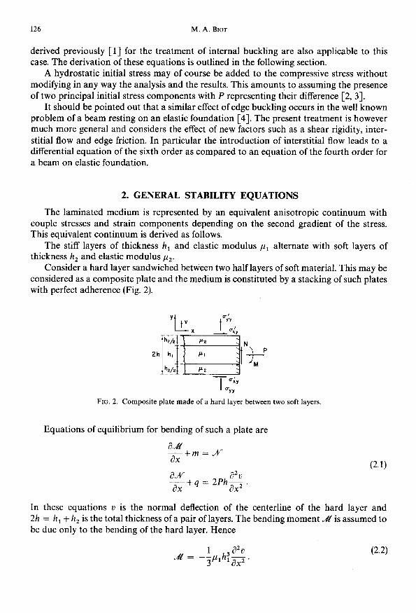
Consider a hard layer sandwiched between two half layers of soft material. This may be considered as a composite plate and the medium is constituted by a stacking of such plates with perfect adherence (Fig. 2).
FIG. 2.
‘f?fff-- - dy I uYY
Composite plate made of a hard layer between two soft layers.
Equations of equilibrium for bending of such a plate are
(2.1)
In these equations u is the normal deflection of the centerline of the hard layer and 2h = h, + h, is the total thickness of a pair of layers. The bending moment _& is assumed to be due only to the bending of the hard layer. Hence
Edge buckling of a laminated medium 127
The couple stress is &‘/2h and corresponds to a bending moment per unit area. The total shear over the cross section is denoted by _M. The external moment applied per unit length is
m = h(t&, + ox,,) z 2ha,,
and the vertical force per unit length is
(2.3)
The average tangential and normal stress in the approximately equivalent continuum are denoted by cXY and oYY. The value of crXY is given by
(2.5)
where L is the average shear modulus of the laminated medium along the layers. As derived earlier [2, 31 its value is
1 L=-----.- (2.6)
where
h, 4 a1 =G a2 = z
are the fractions of the total thickness occupied by each layer. By introducing the values (2.2) (2.3) (2.4) and (2.5) into equations (2.1) they become
-$,h$$+2hL$ = ./V-
g+2hs = 2j=h$. ay
Elimination of JV” between these two equations yields
fpih~~+2h(P-L)~-2h$$’ = 0.
(2.8)
(2.9)
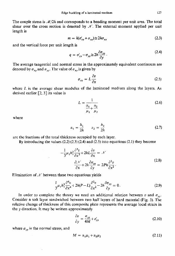
In order to complete the theory we need an additional relation between u and bYY. Consider a soft layer sandwiched between two half layers of hard material (Fig. 3). The relative change of thickness of this composite plate represents the average local strain in the y direction. It may be written approximately
dV - a,,+& ay-4lM
where cYY is the normal stress, and
M = a,~1 +a,~2 (2.11)
128 M. A. BIOT
I =YY
FIG. 3. Soft layer between two hard layers showing interstitial flow ZJ.
is an average elastic modulus of the laminated material as derived earlier [2, 3) under the assumption that the microstrain is the same in the hard and soft materials. If the rigidity contrast of the two materials is large a correction term e;, must be added. The strain (2.10) is assumed to depend only on oYY. This assumption is valid for the purpose of the present theory dealing with deformations where the wavelength along x is much shorter than the wavelength along y. This is further confirmed by applying more elaborate theories which do not introduce this simplifying assumption [2, 3, 51.
The correction term eku enters into play when the modulus ,uu, is much smaller than pl. In this case the soft medium may tend to flow relative to the hard layers with a parabolic distribution of the displacement along x (Fig. 3). We have called this effect interstitial flow [3,5]. It is evaluated as follows.
With the x axis along the centerline of the soft layer the parabolic distribution of displacement is
u= l-$(x) i 1 2
(2.12)
wheref(x) is an undetermined function. The equilibrium condition for the stresses in the soft layer is
!5+!?5?! = 0.
ay (2.13)
The average shear stress across the thickness in this layer is
(2.14)
Combining (2.12) (2.13) and (2.14) yields
f(x) = 5 2. 2
The change of thickness of the soft layer produces an additional strain
eb, = 1 h2’2 au
-- s 2h
-_dy= -%!&
-hz/2 ax
(2.15)
(2.16)
This change of thickness is expressed by means of the microstrain au/ax as the integrand, using the assumption of incompressibility. Elimination off(x) between (2.15) and (2.16)
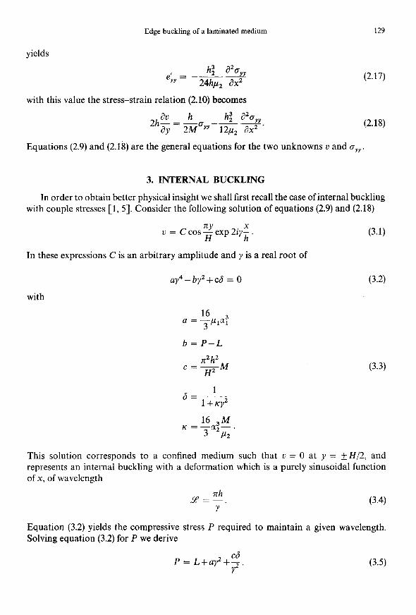
Edge buckling of a laminated medium 129
yields
h; a20Yv 6& = --z 24hp, ax
with this value the stress-strain relation (2.10) becomes
2hd” = k. h; a%,, ay 2M yy-Ep’
(2.17)
(2.18)
Equations (2.9) and (2.18) are the general equations for the two unknowns 2) and oyY.
3. INTERNAL BUCKLING
In order to obtain better physical insight we shall first recall the case of internal buckling with couple stresses [l, 51. Consider the following solution of equations (2.9) and (2.18)
v = Ccos$!exp2iyX. (3.1)
In these expressions C is an arbitrary amplitude and y is a real root of
ay4-by2+cd = 0 (3.2)
with
16 a = -,u,ar:
3
b=P-L
n2h2 c=~M
6= 1
l+
16 3M
K=y”2E’
(3.3)
This solution corresponds to a confined medium such that 0 = 0 at y = &-H/2, and represents an internal buckling with a deformation which is a purely sinusoidal function of x, of wavelength
pL”h. Y
(3.4)
Equation (3.2) yields the compressive stress P required to maintain a given wavelength. Solving equation (3.2) for P we derive
P = L+ay2+?j. (3.5)

130 M. A. BIOT
The minimum of this expression as a function of y yields the critical buckling stress and wavelength. The problem is considerably simplified if we introduce the assumption
6= 1. (3.6)
This amounts to putting e& = 0 in equation (2.10) hence to neglecting the effect of inter- stitial flow. With this assumption the minimum value of (3.5) yields the buckling stress
P = L + 2&c). (3.7) The corresponding value of y is
C+
Y=a’ 0 Hence from expression (3.4) the buckling wavelength
Pi = a*
7th - 0 C
This expression may be further simplified by noting that in practice the rigidity contrast between layers is large so that we may write approximately M s alpI. With this approxima- tion expression (3.9) becomes
zi = 1*90J(h,H). (3.10)
(3.8)
is
(3.9)
If we take into account interstitial flow the value of 6 becomes a function of y through expression (3.3). Finding the minimum of the value (3.5) for P is somewhat more elaborate and may be carried out numerically [ 11. By introducing the same approximation M CT alpI
as above the buckling wavelength zi is represented graphically by plotting
z = 1.9o&g I
as a function of
An approximate expression for this plot is found to be
Hence
.
(3.11)
(3.12)
(3.13)
(3.14)
The bracket represents the correction factor due to interstitial flow. It depends on the i power of 1+(1/2)K and is therefore very insensitive to the parameter K. In many cases for which K is not large the influence of interstitial flow will be negligible and the simple formula (3.10) will be valid for the buckling wavelength.
According to equation (3.7) the buckling stress P is of the order of L. Note that this buckling may occur in the elastic range for a material with strong anisotropy where M
is large relative to L. This will be the case for example in a laminated medium composed of an alternation of hard and soft layers.

Edge buckling of a laminated medium 131
4. EDGE BUCKLING WITH PERFECT SLIP
We replace iy by 1 in the solution (3.1). It becomes
where
and
V = Ccoszexp2L;
0 YY
= -4n6gCsinzexp2nX,
1 d=-
l-?cIZ
(4.1)
(4.2)
aA4+bA2+cd = 0. (4.3)
This solution again represents a confined medium such that u = 0 at y = + H/2. For the case of edge buckling we must consider complex roots I of equation (4.3) with positive real parts. This corresponds to a deformation localized in the region x < 0 near the edge, x = 0. (Fig. 1).
As pointed out in the preceding section, the case of internal buckling is obtained by evaluating the minimum value of P as a function of the wavelength. The present case of edge buckling is derived in quite a different way by introducing boundary conditions at the edge x = 0.
In order to simplify the analysis it is convenient to consider the case where interstitial flow is negligible. As shown above this amounts to putting 6 = 1. Equation (4.3) for il becomes
aA4+bA2+c =O. (4.4)
We choose two complex roots 1 and 1* of this equation with positive real parts. Adding two solutions of the form (4.1) given by these two roots the deflection representing edge buckling is written
u = v() cos Tf H
v0 = C exp 21; + C* exp 2A* X (4.5)
with complex conjugate constants C and C*. The deflection of the center line at y = 0 is given by t+,(x).
Consider boundary conditions at the edge x = 0. We shall assume that no couple stress is applied at the edge. This implies
&2L() 6X2
(x = 0).

132 M. A. BIOT
Another boundary condition involves the total shear .,V over the cross section of area 2h. If there is no friction at the edge the compressive stress P acts in a direction normal to it and the value of M at the edge is
A’” = 2hPe ax
(x = 0).
With this value of M the first equations (2.8) becomes
;p,h$$+2h(P-L)g = 0. (4.8)
(4.7)
This is the second boundary condition. We substitute expression (4.5) into the two boundary conditions (4.6) and (4.8), at x = 0 and obtain
c;1z+c*1*2 = 0
Lz(Cil3+C*L*3)+b(CL+ c*l*) = 0.
By taking into account the characteristic equation (4.4) these equations become
(4.9)
CA2 + c*a.*2
c;+c*; = 0. (4.10)
Elimination of C and C* and cancellation of the factor (A-n*) yields
12+ai*+n*2 = 0. (4.11)
This equation may be expressed by means of the coefficient a, b, c using the relations
(4.12)
b 12+A*2 = --
a
With these values relation (4.11) becomes
b = &I c). (4.13)
By substituting expression (3.3) for b this last equation yields the critical compression for edge buckling
P = L+J(ac). (4.14)
As expected this value is smaller than the value (3.7) required for internal buckling. The roots i and 1* are derived from
aA4+J(aC)12+C = 0 (4.15)
obtained by substituting b = J( a c in equation (4.3). The complex conjugate roots of )

Edge buckling of a laminated medium 133
(4.15) with positive real parts are
A* = f ae-W3. 0 (4.16)
Equations (4.10) and (4.16) require the constants to be of the form,
C = icein/ C* = _ iCre-i”/3. (4.17)
By using equation (3.9) the roots (4.16) may be expressed by means of the wavelength A$ for internal buckling. We write
With these results the deflection (4.5) of the center line becomes
u0 = -2Cexp(g) sin (rcJ3;+;).
The wavelength of edge buckling is therefore
L$‘= $Zi = 1.16Zi.
(4.18)
(4.19)
(4.20)
Hence it is slightly larger than for internal buckling. The amplitude damps out rapidly with the distance from the edge as illustrated in Fig. 4(a).
FIG. 4. Deflection q,(x) of the centerline: (a) with perfect slip at the edge; (b) with imperfect slip at the edge.
5. EDGE BUCKLING WITH IMPERFECT SLIP
We shall consider the case where perfect slip is prevented by an elastic restraining force acting at the edge x = 0. The boundary condition (4.7) is now replaced by
JV = 2hP?-kv ax ’ (5.1)
The additional term - ku represents an elastic force opposed to the deflection II, acting over the thickness 2h of the composite plate at the edge. The other boundary condition (4.6)

134 M. A. BIOT
corresponding to the absence of couple stress at the edge remains the same. Proceeding as before, using expression (2.8) for JV” we derive the two boundary conditions at x = 0
a% o -= ax2
$rh$$+2h(P-L)&ko = 0. (5.2)
Again we shall assume that interstitial flow is negligible, putting 6 = 1. The solution v is then of the form (4.5) with the two complex conjugate roots ;i and 1* of equation (4.4). Substitution of the solution (4.5) into the boundary conditions (5.2), taking into account equation (4.4), yields,
CA2 + c*1*2 = 0
(;+;)c+(;+;)c* = 0. (5.3)
By elimination of the constants C and C* and cancellation of the factor (A-- A*) in the resulting equation we obtain
(12+~1*+1*2)+$11*(1+1*) = 0. (5.4)
Due to relations (4.12) for the roots 3, and I* we further derive
L+I* = J[ -$+2/i] (5.5)
(5.6)
and equation (5.4) may be written
r-l = Ad(2-r)
with
(5.7)
The value of r as a function of A is obtained by solving equation (5.6). Knowing r, the critical compressive stress P for edge buckling is derived from the relation
b = P-L = rd(uc). (5.8)
The roots 1 and 1* are derived by substituting this value of b into equation (4.4). It becomes
aA4 + rJ(a c)A.’ + c = 0. (5.9)
The roots are
(5.10)
Edge buckling of a laminated medium 135
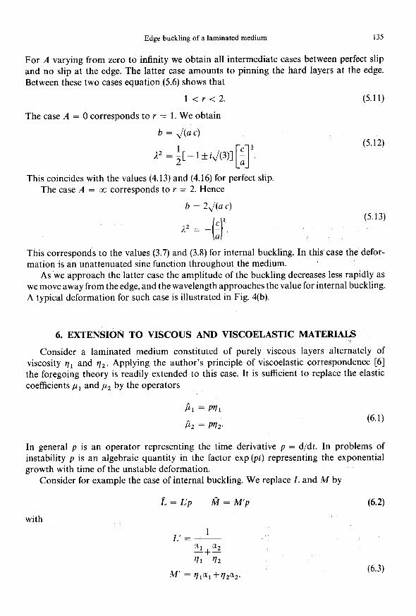
For A varying from zero to infinity we obtain all intermediate cases between perfect slip and no slip at the edge. The latter case amounts to pinning the hard layers at the edge.
Between these two cases equation (5.6) shows that
l<r<2. (5.11)
The case A = 0 corresponds to r = 1. We obtain
b = &c) c+ A2 +-lkiJ(3)] ; . [I
(5.12)
This coincides with the values (4.13) and (4.16) for perfect slip. The case A = cc corresponds to r = 2. Hence
b = 2& c)
C+ A = 12 __.
0 u
(5.13)
This corresponds to the values (3.7) and (3.8) for internal buckling. In this case the defor- mation is an unattenuated sine function throughout the medium.
As we approach the latter case the amplitude of the buckling decreases less rapidly as we move away from the edge, and the wavelength approaches the value for internal buckling. A typical deformation for such case is illustrated in Fig. 4(b).
6. EXTENSION TO VISCOUS AND VISCOELASTIC MATERIALS
Consider a laminated medium constituted of purely viscous layers alternately of viscosity y~r and q2. Applying the author’s principle of viscoelastic correspondence [6] the foregoing theory is readily extended to this case. It is sufficient to replace the elastic coefficients ,ur and ,u2 by the operators
$1 = PI;Il
P2 = PV2. (6.1)
In general p is an operator representing the time derivative p = d/dt. In problems of
instability p is an algebraic quantity in the factor exp (pt) representing the exponential growth with time of the unstable deformation.
Consider for example the case of internal buckling. We replace L and M by
2 = L’p ti = M’p (6.2) with
(6.3)

136 M. A. BIOT
Hence the parameters a and c of equations (3.3) are replaced by the operators
A , 16 3 a = up = --_Illn,p
3
h2 2 = c’p = n2 -M’p.
H2
(6.4)
By correspondence equation (3.5) becomes
P - = L’+u.;,2+$ P
where 6 is
(6.5)
6=1 16 M’
1 +Ky2
K=-_iY;- 3 ?I;
(6.6)
For a given value of the compressive stress P equation (6.5) shows that there is a wavelength
Y = nh/y for which p is a maximum. This is the wavelength of maximum amplitude rate of growth or dominant wavelength. This wavelength has the same value as for elastic internal buckling. If we neglect interstitial flow putting 6 = 1 the dominant wavelength is given by the same expression (3.10) as in the elastic case. The value ofp which measures the amplitude rate of growth is proportional to P and is given by
$ = L’+2J(a’c’). (6.7)
The general case of edge buckling analyzed in section 5 is also readily extended to viscous media. We replace k by the operator
I% = k'p (6.8)
where k’ is a coefficient of viscous friction at the edge. The value of A is now
(6.9)
and equation (5.6) yields the value of Y. The roots 1 are derived from equation (5.10). Hence
A2 = J$-r+iJ(4-r2)] $ [I
‘. (6.10)
From relation (5.8) by correspondence from the elastic case, we derive
g = L’ + rJ(a’c’). (6.11)
Since r < 2, the value of p is larger than the value derived from (6.7) for viscous internal
buckling. Hence the amplitude due to viscous edge buckling tends to grow faster and will
generally overshadow the appearance of internal buckling. The same general conclusions derived for elastic media are applicable to viscous media.
For instance as the friction at the edge increases, hence for increasing values of k’ the amplitude of the deformation decreases less rapidly as we move away from the edge, up

Edge buckling of a laminated medium 137
to the case of infinite friction where the buckling deformation is represented by a sine function of constant amplitude.
Identical behavior is also obtained for viscoelastic materials defined by operators ,L1 = V&P) & = ~;lJ(p) k = k’f(p) with the same increasing function f(p).
Finally, by formal correspondence, the results may be extended to viscoelastic materials represented by operators which are completely general. However, the physical behavior must be the object of a separate analysis for each case.
REFERENCES
[l] M. A. BIOT, Further development of the theory of internal buckling of multilayers. Bull. Geol. Sot. Am. 76, 833-840 (1965).
[2] M. A. BIOT, Internal buckling under initial stress in finite elasticity. Proc. R. Sot. A273, 306328 (1963). [3] M. A. BIOT, Mechanics of Incremental Deformations, p. 504. Wiley (1965). [4] M. HETENYI, Beams on Elastic Foundations, p. 225. University of Michigan Press (1946). [5] M. A. BIOT, Rheological stability with couple stresses and its application to geological folding. Proc. R. Sot.
A298,402423 (1967). [q M. A. BIOT, Variational and Lagrangian methods in viscoelasticity. IUTAM Colloquium on Deformation
and Flow of Solids, Madrid, 1955, pp. 251-263. Springer (1956).
(Received 13 March 1967; revised 5 July 1967)
A6CTpaKT--~oKa3aHo, 9TO B JIaMEiHapHOi CpeAe, IlOjV3CpXCeHHOZi 'SKPTHH), nORBJllleTCR HeCTa6WIbHOCTb,
KOTOpaRElMeeTMeCTOB6~U3UOTpe3aHOrOKpaRne~neHAHKy~RpHOKC~ORM.~~BOA~TCKO6~~eyp~BHeH~K
AnSI ClIynaSI ~OIIOrWIeCKOrO paBHOBeCHR JIaMElHapHbIX CpeA, KOTOpbIe npHMeHRIoTCK B qaCTHOM CJIyqae
“KpaerOrO BbInyYIiBaHIId'. Teopw 3aKmxaeT ~@&KT “npoMexyTorHor0 Tesemff". IIocneACTBHe
npHHUEiIIa aBTOpa, KaCaIOlqerOCK JBBUCHMOCTH, pe3yJIbTaTbI BamHbI AJIK MeTepklalIOB ynpyrliX,BR3KAX
Ii BSl3KOyIIpyrliX. Y'iHTbIBaeTCR BJ'IWlIiEIe TpeHASl Ha KpaKLPaClreT MOlKHO PaCCMaTpHBaTb KaK pa3BHTUe
TeOpHHnepBOHa~a~bHOHanpflXeHHbIXeHE130TpOnHbIXCpe~,TaKYT06bIBKJIH)YIITbMOMeHTHbIeHanpK~eH~X
3aBucm4ocTb rpanAeHTa HanpnmeHm OT nepebfeluemx.