Edgar Sánchez-Sinencio Instructor: Office: 318E WERC, Tel. (979) 845-7498 Tu Th 2…s-sanchez/622...
34
or: Edgar Sánchez-Sinencio 18E WERC, 9) 845-7498 u Th 2:20-3:35pm ETB 1003 [email protected] ours: M W 1:00-2:25 pm Analog and Mixed-Signal Center (AMSC), TAMU 1
Transcript of Edgar Sánchez-Sinencio Instructor: Office: 318E WERC, Tel. (979) 845-7498 Tu Th 2…s-sanchez/622...
Instructor: Edgar Sánchez-Sinencio
Office: 318E WERC,
Tel. (979) 845-7498
Tu Th 2:20-3:35pm
Room: ETB 1003
mail: [email protected]
Office Hours: M W 1:00-2:25 pm
Analog and Mixed-Signal Center (AMSC), TAMU
1

1.To understand and design CMOS active filters.
Emphasize the integrated circuit design aspects of
practical filters for a host of applications and frequency
ranges.
2. To use properly the filter approximation suitable for
each particular application.
3.To identify tradeoffs of filter implementation types
such as Active-RC, OTA-C, Gm-C, Active-R, Ring
Oscillator integrator based and Switched-Capacitor.
Trade-offs of performance, design simplicity and cost
will be explored.
GOALS
2

Electronic Filters are fundamental elements in
the majority of applications such as Base band receivers, consumer electronics, sensor interfaces,
oscillators, PLL, hearing aids, switching converter loop control, and audio amplifiers among many others.
The main topics are filter approximation, filter topology and circuit implementations. Selection of approximations and filter topologies and implementations are very much application dependent.
Analog and Mixed-Signal Center (AMSC), TAMU
INTRODUCTION
3

Evolution of Analog Filters
• Motivation and historical background
Before 1974
– Passive LC type
– Discrete Active-RC
– Thin Film Hybrid Integrated Circuits
• Monolithic Filters (After 1980)
– MOSFET-C, - Transconductance- Capacitor
(OTA-C), - Switched-Capacitor, - Switched
Current (SI), Log-Domain
• RF Integrated Filter ( After 1996)
– Active RLC prototype
Wireless
Communications
Analog and Mixed-Signal Center (AMSC), TAMU
4

5
Continuous-Time Filters beyond the conventional active-RC
and Gm-C are the following filter implementations:
Active-R
Switched-R
Ring Oscillator Based
PWM Based
Inverter Based OTA-C
These filters have been revisited or proposed in the last few years.
Advantages and disadvantages on these filter implementation as
well as power, area, linearity, and noise tradeoffs determine the
selection of the implementation.
Baseband filters required in Receiver have to continuously evolved
to meet new Communication Standards.

Filters Historical Background
The early years
- The origin of electronic filters dates back to 1915
when K.W. Wagner and G.R. Cambell from
Germany and USA, respectively introduced
passive electric wave filters to meet the needs of
the young communications industry.
- One of the major applications of the passive
lumped filter has been in the design and
implementation of channel bank filters in
frequency-division multiplex (FDM) telephone
system.
A741
Analog and Mixed-Signal Center (AMSC), TAMU 6

Historical Background
The early years
- From the early 1920s to the latter 1960s
the majority of voice-frequency filters were
realized as discrete RLC networks.
- In the 1950s, a goal to reduce the size and cost of
inductors by replacing them by active circuits was
launched. That is, the design of inductorless filters.
- The first book on Active RC filters was: L.P.
Huelsman, “ Theory and Design of Active RC
Circuits, Mc Graw-Hill Book co., NY 1968.
- Early 1970s Thin-film hybrid integrated circuits
were developed.Analog and Mixed-Signal Center (AMSC), TAMU
A741
7

Development of good quality active components
– John Ambrose Fleming, in 1904, files a patent for the
vacuum tube (diode)
- Lee De Forest, in 1907, and R. Von Lieben invented the
amplifier vacuum tube (triode). Five years later in 1912
he developed the audion amplifier with a gain of 120
v/v.
- Eccles and Jordan in 1919 invented the flip-flop circuit,
a key component for computers in the 40’s.
- In 1948, Bardeen, Brattain and Schockley discovered
the transistor.
- Gordon Teal at Texas Instruments, in 1954, introduces
the silicon transistor, which is much cheaper to produce
Historical Background
8

Development of good quality active components
- In 1958, J. Kilby and R. Noyce separately invented the
integrated circuit. In 1970, RCA introduced the MOS
technology for the fabrication of IC.
- In 2000, J. Kilby receive the Nobel Prize in Physics for
his work in Integrated Circuits.
9
Development of good quality active components
- Early Op Amps in the 1940s were implemented
with vacuum tubes.
- The first monolithic silicon Op Amp was
developed in the early 1960’s by Robert J.
Widlar at Fairchild.
- In 1968 the popular uA 741 Op Amp become
the industrial standard.
- Today, the cost of a general purpose Op Amp is
less than the price of a cup of coffee.
- The Operational Transconductance Amplifier
(OTA) was first fabricated by RCA in 1969.
Historical Background
10

Development of active filters
Since Op Amps were expensive components, the
first active filters used architectures with only one
Op Amp for Biquadratic Filters.
It is interesting to note that current RF filters due to
the limited allowable power consumption they use
only few transistors as the active components, and
the rest of the filters involve passive components
such R, L and Cs. Research for this type of low
power, high frequency filters is currently in
progress.
Historical Background
11

Development of Monolithic Analog Filters
- Due to the difficulty in making fully integrated
resistors, in the 70s the active RC filters were not
able to fabrication in monolithic form on one
silicon chip.
- Practical Switched-Capacitor filters
characterized in the Z-domain were developed in
the late 70s* and earlier 80s. SC filters have good
accuracy compared with continuous-time filters._________________________________________________________________
* D. L. Fried, “Analog sample-data filters,” IEEE J. Solid-State Circuits
(Corresp.), vol. SC-7, pp. 302-304, Aug. 1972.
Historical Background (cont.)
12
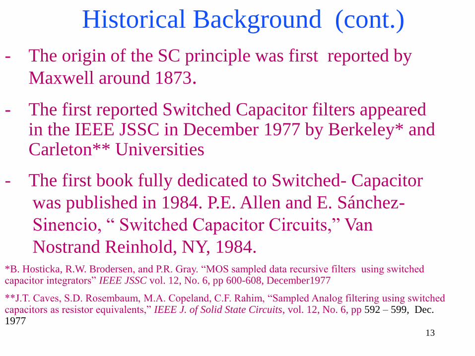
- The origin of the SC principle was first reported by
Maxwell around 1873.
- The first reported Switched Capacitor filters appeared in the IEEE JSSC in December 1977 by Berkeley* and Carleton** Universities
- The first book fully dedicated to Switched- Capacitor
was published in 1984. P.E. Allen and E. Sánchez-
Sinencio, “ Switched Capacitor Circuits,” Van
Nostrand Reinhold, NY, 1984.*B. Hosticka, R.W. Brodersen, and P.R. Gray. “MOS sampled data recursive filters using switched capacitor integrators” IEEE JSSC vol. 12, No. 6, pp 600-608, December1977
**J.T. Caves, S.D. Rosembaum, M.A. Copeland, C.F. Rahim, “Sampled Analog filtering using switched capacitors as resistor equivalents,” IEEE J. of Solid State Circuits, vol. 12, No. 6, pp 592 – 599, Dec. 1977
Historical Background (cont.)
13

was published in 1984 by P.E. Allen and E.
Sánchez-Sinencio, “ Switched Capacitor Circuits,”
Van Nostrand Reinhold, NY, 1984.
- Switched-Current filters searching for reduced
complexity and higher speed were proposed
in the late 80s and early 90s.
- By substituting Rs in Active RC Filters the
MOSFET-C Filters were born around 1985.
- A nonconventional approach using
transconductance amplifiers in open loop and
capacitors the OTA-C Filters were developed in
the middle 80s.
Historical Background (cont.)
Analog and Mixed-Signal Center (AMSC), TAMU14

Development of Monolithic Filters
- Current-mode filters using simple
transconductors ( transistors) and current-
mirrors were developed in 92.
- RF filters are revisited in the last 5 years,
search for on chip inductors is vital.
- Log domain filters for high tunability and
low voltage supply were also investigated
Historical Background (cont.)
Analog and Mixed-Signal Center (AMSC), TAMU15

SAMPLED- DATA
FILTERS
• SWITCHED -CAPACITOR
• SWITCHED – CURRENT
• SWITCHED-R
• PWM BASED FILTER
+ DIGITAL
Monolithic Integrated Filters
CONTINUOUS-
TIME FILTERS:
Active RC
OTA-C
Active-R
CURRENT-MODE
RING OSCILLA-
TOR BASED
RF- FILTERS
- BIPOLAR
- CMOS
- SiGe
HARD DISK DRIVE, SIGMA DELTA ADCs, TRANSCEIVERS,
MEDICAL, HEARING AIDS AND SENSORS APPLICATIONS 16
Active R-C Filters• This approach is inspired on passive filters. Passive
filters are mainly composed by R, C, L ( and often with
transformers).
• A large number of contributions dealing with passive filters and
mathematical approximation satisfying the filter specifications
were developed in the 30’s and 40’s.
• Passive filters are not suitable for audio applications due
to the bulky inductors required. Thus other alternatives
were investigated in the 60’s and 70’s
• Before the invention of transistors and Op Amps, passive
filters were the dominant technology used from audio to
microwave applications. They are back for specs requiring high
linearity. See ADSL and hard-drive applications.
• Thus the inductor, in the passive filters, was replaced by a circuit
capable to emulate it, for frequencies below a few hundred of
MHz.Analog and Mixed-Signal Center, TAMU
17

Active R-C Filters (cont.)• A host of approaches for active-RC were developed among them:
1. Substitute the inductors by active simulators composed of
Op Amps, Rs, and Cs.
2.a)- Emulate the equations of the RLC filter
(Leap Frog Realization)
b)- Emulate transformers in a RLC-transformer prototype.
3. Convert the passive filter into a filter consisting of frequency
dependent negative resistors (FDNR)
4. Based on State-variable techniques.
Analog and Mixed-Signal Center, TAMU
18

MOSFET-C Filters
• In this approach an active-RC filter is
transformed into a MOSFET-C filter. The basic
transformation is obtained by substituting resistors in the
original active-RC filter prototype by MOS transistors.
• The advantage is that the transformed filter can easily
be integrated. Most of the properties of the original filter
prototype are retained by the MOSFET-C filter. The time
and frequency response ideally remained the same.
• Drawbacks are the nonlinearity introduced by the
MOSFET,as well as the maximum peak swing limited by
the tuning voltage.
Analog and Mixed-Signal Center, TAMU
19

SWITCHED-R Filters
• In this approach an active-RC filter is
transformed into a switched-R filter. The basic
transformation is obtained by substituting resistors in the
original active-RC filter prototype by a switched-R.
• The advantage is that the transformed filter can easily
be tuned digitally. Most of the properties of the original
filter prototype are preserved. The time and frequency
response depend on the duty cycle (D) of the switched-Rs.
• Drawbacks are the nonlinearity introduced by the
clock signal of the switched-R, as well as stricter Op Amp
requirements.
Analog and Mixed-Signal Center, TAMU
20
OTA-C Filters
• In contrast to MOSFET-C Filters, OTA-C Filters operate in
open loop fashion. The design parameters are the capacitors
and the transconductance gains. OTA-C = Gm-C
• In principle, tuning and swing can be made independent
from each other. Gm-C might be better than MOSFET-C since
no fundamental limit exists for its maximum swing.
• Gm-C operate at higher frequency due to the limited internal
high impedances nodes.
Analog and Design Center, TAMU 21

Continuous-Time Current-Mode Filters
• High-frequency and low voltage applications motivated
researchers to search for alternative filter design style.
• Groups at Texas A&M University and Carnegie Mellon, in 1991
independently developed an approach based on current-mirrors
and simple transconductors ( one driven transistor) capable to
operate at frequencies up to fundamental limits of the MOSFET.
• Due to the small voltage swings, and low bias overhead
requirements, current-mode filters work well with a 1.8 V supply
• This technique is well suited to standard digital CMOS processes
Analog and Mixed-Signal Center (AMSC), TAMU 22

Continuous-Time Filter Properties
• Transconductance- and current-mode filters are suitable for
high-speed, reduced silicon area and moderate accuracy.
• Read Channel filters are examples of practical Gm-C filters
• However, due to process and temperature variations, these
filters require tuning circuitry. Frequency tuning has been
accomplished within 1% accuracy. This is not the case for Q-
tuning for Q >5, where only a modest 25 to 30% accuracy
has been reached, until recently where a 1% accuracy was
obtained.
• Practical Q-tuning is still a difficult problem.
Analog and Mixed-Signal Center (AMSC), TAMU23
Switched-Capacitor Filters
• Switched-Capacitor (SC) techniques , led to the
first use of fully integrated complementary metal
oxide semiconductor (CMOS) . The fact that
MOSFET, Cs together with Op Amps can be mass
produced on silicon led to a breakthrough in active
filter design.
• SC filters operate on the principle of transferring
analog signal samples ( represented as charges on
capacitors) from one storage element to another
• SC advantages are the accuracy, and digital
programming.Analog and Mixed-Signal Center (AMSC), TAMU
24

Switched-Capacitor Filters
• The time constant associated with RC of active filters can be expressed as follows:
Tc = ReqC= (T/Cr)C = (C/Cr)(1/fs)
Tc is the time constant, the equivalent resistor (Req)
is equal to the sampling period divided by a
capacitor Cr. Accuracy of Tc is better than 0.1%
• We will explore how to design high-Q SC Biquad filters, and ladder filters.
Analog and Mixed-Signal Center (AMSC), TAMU25

Switch representation
CMOS Switch
Implementation
Vdd
Mn
Mp
VoVin
CMOS Switch implementation and low
voltage effects in deep submicron technologies
0Vin/Vdd
Gn
Gn Gp
Gp
On-conductance CMOS
switch vs. drain (source)
voltage for different Vdd
26

How to tackle the limitations of switches for
low power supply ?
• Clock voltage multiplication, i.e., charge pump,
supply voltage doubler
• Multiple threshold values process technology, (
Low Vt for switches)
• Switched Op amps
Analog and Mixed-Signal Center (AMSC), TAMU27
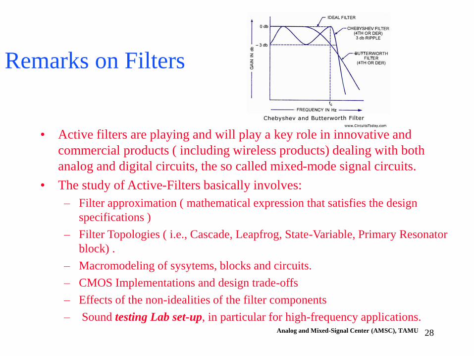
Remarks on Filters
• Active filters are playing and will play a key role in innovative and
commercial products ( including wireless products) dealing with both
analog and digital circuits, the so called mixed-mode signal circuits.
• The study of Active-Filters basically involves:
– Filter approximation ( mathematical expression that satisfies the design
specifications )
– Filter Topologies ( i.e., Cascade, Leapfrog, State-Variable, Primary Resonator
block) .
– Macromodeling of sysytems, blocks and circuits.
– CMOS Implementations and design trade-offs
– Effects of the non-idealities of the filter components
– Sound testing Lab set-up, in particular for high-frequency applications.Analog and Mixed-Signal Center (AMSC), TAMU 28
What should we know at the end
of the course?
What are the fundamental concepts
that are practically time-invariant?
ECEN 622
(ESS)
ACTIVE
FILTER
SYNTHESIS
By Edgar Sanchez-Sinencio, Analog and Mixed Signal Center, TAMU

• How old is the theory of filters and why is still important?
•What are the types of filter used in integrated circuits?
-Passive, active, continuous-time, discrete time, linear
• How can we mathematically express the filter transfer
functions? What is the difference between synthesis
and analysis?
• Are there different filter expressions that meet the same
filter requirements ?
By Edgar Sanchez-Sinencio, Analog and Mixed Signal Center, TAMU

• Why filters are implemented using different
methodologies such as active-RC, Switched-
capacitors, OTA-C, active LC, Active-R, Switched-
R?
• Can we use the same mathematical descriptions to
deal with a discrete-time filter and continuous-time
filter?
• Are these filter implementations accurate?
• Can inaccuracies on the filter performance be
alleviated, how?

• Can one design a bandpass filter using only
Rs and Cs ?
• What are the implications to have real poles
or complex poles in a filter transfer function?
• What are complex filters and where are they
used?
• What are adaptive filters?
• What filters are typically used in receivers?

•What are the application areas where filters are used?
•Are digital filters eliminating the use of analog ones?
• What are the filter design trade-offs and why are they
of practical interest?
• Do you know how many companies use filters in
their products?
• How often are papers published on filters and
since when?
• What are the main areas related to patent filters?

• What are the complementary fields to study
filters?
-Control systems dealing with stability and adaptive
systems.
- Communications dealing with standards,
modulation and system level design.
- Microwave Circuits dealing with transmission
lines, matching networks and antennas.
- Process technology and modeling that limit the
filter performance.
- Digital Signal Processing to tune analog
components