Edelbrock E-Force Supercharger - CatalogRack...2015-2016 Jeep Wrangler TCM Removal (Auto Trans Only)...
35
Edelbrock E-Force Supercharger 2012-16 JEEP WRANGLER JK 3.6L V6 Part #1527, 1528 and 15270
Transcript of Edelbrock E-Force Supercharger - CatalogRack...2015-2016 Jeep Wrangler TCM Removal (Auto Trans Only)...

Edelbrock E-Force Supercharger2012-16 JEEP WRANGLER JK 3.6L V6
Part #1527, 1528 and 15270


WARNING!The supercharger bypass valve is factory installed and adjusted intended to be vacuum operated only. DO NOT move the solenoid actuator lever by hand or adjust the stop point. Moving the lever manually will damage the solenoid and the system will not function prop-erly. Damage to the bypass assembly from manual movement will not be covered under manufacture warranty.


2012-2014 Vehicles ONLYIf your ECM has been previously flashed by a Superchips programmer, the ECM must be shipped to Edelbrock for calibration. Please email your Name, Address, phone number and email address to: [email protected]. DO NOT purchase a new ECM.
2015-2016 Vehicles ONLY
USA CUSTOMERS ONLY:In order to properly calibrate your vehicle for this supercharger kit, the ECM and TCM must be removed from the vehicle, packaged and shipped to Edelbrock. Your vehicles computers will be modified and or flashed for supercharger kit compatibility. Part number 1528 contains a box for shipping both the ECM and TCM to Edelbrock. (See ECM/TCM removal procedures on the following pages.)
NOTE: Please email your Name, Address, phone number and email address to [email protected] and a prepaid return label will be sent. Affix the label to the package and drop it off at any UPS Store in your area.
The calibration process will take approximately 8-10 business days from the time your vehicles comput-ers are received. To avoid unplanned vehicle down time, we recommend that the computers be shipped out BEFORE beginning the supercharger installation.
INTERNATIONAL (NON-USA) CUSTOMERS PLEASE CALL EDELBROCK TECHNICAL SUPPORT AT (800)-416-8628.
IMPORTANT CALIBRATION DETAILS
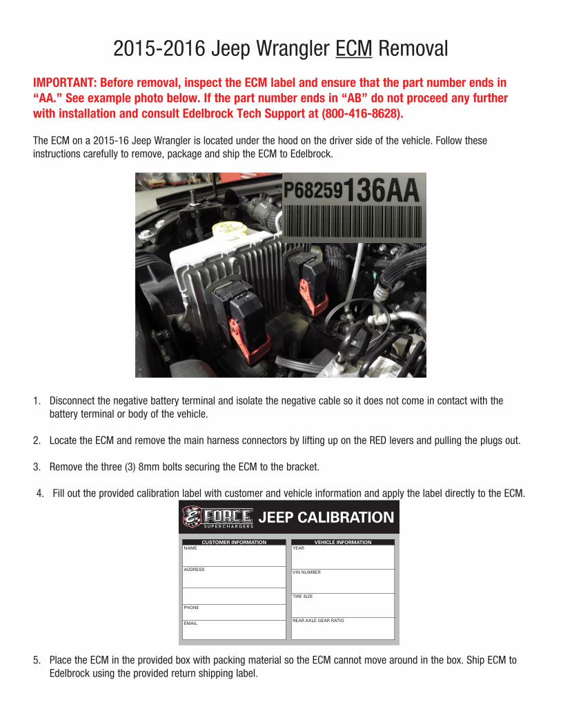
2015-2016 Jeep Wrangler ECM RemovalIMPORTANT: Before removal, inspect the ECM label and ensure that the part number ends in “AA.” See example photo below. If the part number ends in “AB” do not proceed any further with installation and consult Edelbrock Tech Support at (800-416-8628).
The ECM on a 2015-16 Jeep Wrangler is located under the hood on the driver side of the vehicle. Follow these instructions carefully to remove, package and ship the ECM to Edelbrock.
1. Disconnect the negative battery terminal and isolate the negative cable so it does not come in contact with the battery terminal or body of the vehicle.
2. Locate the ECM and remove the main harness connectors by lifting up on the RED levers and pulling the plugs out.
3. Remove the three (3) 8mm bolts securing the ECM to the bracket.
4. Fill out the provided calibration label with customer and vehicle information and apply the label directly to the ECM.
JEEP CALIBRATIONCUSTOMER INFORMATION
NAME
ADDRESS
PHONE
VEHICLE INFORMATIONYEAR
VIN NUMBER
TIRE SIZE
REAR AXLE GEAR RATIO
5. Place the ECM in the provided box with packing material so the ECM cannot move around in the box. Ship ECM to Edelbrock using the provided return shipping label.

2015-2016 Jeep Wrangler TCM Removal (Auto Trans Only)The TCM on a 2015-16 Jeep Wrangler is located under the steering column on the driver side of the vehicle. Follow these instructions carefully to remove, package and ship the TCM to Edelbrock.
1. Disconnect the negative battery terminal and isolate the negative cable so it does not come in contact with the battery terminal or body of the vehicle.
2. Remove the trim panel directly under the steering column by carefully pulling straight out on the panel by hand in the locations indicated below.
3. Using a 10mm socket, remove the two bolts that secure the wire cover plate.
4. Locate the TCM on the right side of the wiring compartment. The TCM will have two harness connections at the bottom with a white barcode label.
5. Remove the two TCM harness connections by depressing the clips holding them in place.
6. Remove the TCM from the retaining bracket by depressing the clips holding the module’s ears in on both sides of the bracket. Gently pull the TCM out of the bracket from the bottom first.
7. Fill out the provided TCM calibration label with customer and vehicle information and apply the label directly to the TCM.
8. Place the TCM in the provided box with packing material so the TCM cannot move around in the box. Ship the TCM to Edelbrock using the provided return shipping label.


Page 1
Edelbrock E-Force Supercharger System 2012-16 Jeep Wrangler JK 3.6L V6
Installation Instructions
©2017 Edelbrock LLCPart #1527, 1528, 15270
Brochure #63-1527Rev. 5/17/17 - NP
Thank you for purchasing the Edelbrock Supercharger System for the Jeep Wrangler with 3.6L V6 Pentastar. This is a front drive, front inlet, blow down supercharger system using Eaton’s TVS1320 rotor group. The supercharger housing is mated to a lower manifold assembly which houses a dual pass intercooler measuring in at 11” long by 3.5” wide and 1.5” thick.
The supercharger is 50-State emissions legal (pending), and includes a 3-year 36,000 mile warranty, where applicable, so there are no worries when installing on a brand new vehicle.
INTRODUCTION
TOOLS AND SUPPLIES REQUIRED z Jack and Jack Stands or Service Lift z Ratchet and Socket Set including but not limited to: 1/4 Drive: 8mm, 10mm and Universal Joint3/8 Drive: 8mm, 10mm,13mm, 15mm, 16mm, 24mm,
Deep: 9mm, 19mm 1/2 Drive: 24mm
z Wrench Set including but not limited to: 8mm, 10mm, 17mm
z Breaker Bar: 1/2” z Right Angle Drill and 1/4” Drill Bit z Utility Knife z Radiator Cooling System Vacuum Purge and Refill Kit or Spill-Free Funnel
z Compressed Air/Vacuum z Panel Puller z Flat Blade & Phillips Screwdrivers z 50/50 Coolant Mixture z Side Cutters z 5/16” Fuel Line Removal Tools z Torque Wrench z Pliers OR Hose Clamp Removal Tool z Blue Thread Retaining Compound z O-ring Lube z Masking Tape z Shop Rags z Wire Ties
Before beginning the installation, use the enclosed checklist to verify that all components are present in the box then inspect each component for damage that may have occurred in transit. If any parts are missing or damaged, contact Edelbrock Technical Support (800-416-8628), not your parts distributor.
IMPORTANT WARNINGS
Due to the complexity of the Edelbrock E-Force Supercharging system, it is recommended that this system only be installed by a qualified professional with access to a service lift, pneumatic tools, and a strong familiarity with automotive service procedures. To qualify for the Powertrain Warranty, the E-Force supercharger system must be installed by a Certified ASE Technician at a licensed business, Chrysler/Jeep Dealership, or an Authorized Edelbrock E-Force installer. Failure to do so will void and/or disqualify any and all warranties offered with this system. Please contact the Edelbrock Technical Support department if you have any questions regarding this system and/or how your installer of choice will affect any warranty coverage for which your vehicle may qualify.
WARNING: If your PCM has been programmed with anything other than an SCT programmer, please contact Edelbrock Tech Support at (800) 416-8628 before flashing your PCM. FAILURE TO DO SO COULD RENDER THE PCM INOPERABLE! Edelbrock is not liable for any recovery fees, including but not limited to, replacement of PCM, programmer and/or PCM flashing fees.

Page 2
Edelbrock E-Force Supercharger System 2012-16 Jeep Wrangler JK 3.6L V6
Installation Instructions
©2017 Edelbrock LLCPart #1527, 1528, 15270
Brochure #63-1527Rev. 5/17/17 - NP
Any equipment that directly modifies the fuel mixture or ignition timing of the engine can cause severe engine damage if used in conjunction with the Edelbrock E-Force Supercharger System. This includes, but is not limited to: OBDII programmers, MAF sensors, adapters and any other device that modifies signals to and/or from the ECU. Aftermarket bolt-on equipment such as underdrive pulleys or air intake kits will also conflict with the operation of the supercharger and must be removed prior to installation. Use of any of these products with the E-Force Supercharger could result in severe engine damage.
Any previously installed aftermarket tuning equipment must be removed and the vehicle returned to an as stock condition before installing the supercharger.
91 octane or higher gasoline is required at all times. If your vehicle has been filled with anything less, it must be run until almost dry and refilled
with 91 or higher octane gasoline twice prior to installation.
Any failures associated with not using premium 91 octane gasoline or higher, will be ineligible for warranty repairs.
IMPORTANT WARNINGS CONT’D
It is recommended that you check the Edelbrock Tech Center Website for any updates to this installation manual. Please refer to the lower right hand corner to verify that you have the latest revision of this installation manual before beginning the installation.
Tech Center: http://www.edelbrock.com/automotive_new/misc/tech_center/install/index.php
Edelbrock Authorized Installer DisclaimerAuthorized installers of Edelbrock products are independent companies over which Edelbrock has no right of control. Edelbrock LLC makes no claims regarding the abilities, expertise or competency of individual employees of any authorized installer. Each authorized installer is an independent company and makes its own independent judgments. Edelbrock LLC specifically disclaims any responsibility to any party including third parties for the actions, or the failure to act, of individuals, agents or a company authorized in the installation of Edelbrock LLC products.
WARNING: Installation of this supercharger will result in a significant change to the performance characteristics of your vehicle. It is highly recommended that you take some time to familiarize yourself with the added power, and how it is delivered. This must be done in a controlled environment. Take extra care on wet and slippery roads as the rear tires will be more likely to lose traction with the added power. It is never recommended to turn off your vehicles traction control system.
Proper installation is the responsibility of the installer. Improper installation will void all manufacture’s standard warranties and may result in poor performance and engine or vehicle damage.
Inspect all components for damage that may have occurred in transit before beginning installation. If any parts are missing or damaged, contact Edelbrock Technical Support, not your parts distributor.

Page 3
Edelbrock E-Force Supercharger System 2012-16 Jeep Wrangler JK 3.6L V6
Installation Instructions
©2017 Edelbrock LLCPart #1527, 1528, 15270
Brochure #63-1527Rev. 5/17/17 - NP
Bag #1
INSTALLATION HARDWARE IDENTIFICATION GUIDE (Parts Are Not To Scale)
(1) - Spacer, Alternator Support
Bag #2
Bag #3
(1) - Spacer, FEAD Bracket
(1) - Bolt, Countersink, M10 x 1.5 x 55mm
(1) - Bolt, Hex Flange, M10 x 1.5 x 130mm
(2) - Bolt, Hex Flange, M8 x 1.25 x 30mm
(1) - Bolt, Hex Flange, M8 x 1.25 x 40mm
(1) - Bolt, Hex Flange, M8 x 1.25 x 75mm
(1) - Bolt, Hex Flange, M8 x 1.25 x 20mm
(1) - Bolt, Hex Flange, M10 x 1.5 x 110mm
(1) - Bracket, Alternator Support
(1) - M10 Hex Nut(1) - M8 Washer
(1) - Drill Bit, Countersink
(6) - Bolt, Hex Flange, M6 x 1.00 x 10mm
(4) - Bolt, Hex Flange, M6 x 1.00 x 12mm
(2) - Bolt, Hex Flange, M8 x 1.25 x 20mm
(8) - 3/4” Hose Clamp
(2) - M6 Nut
(2) - M8 Washer
(1) - Bolt, SHCS, M6 x 1.00 x 65mm (10) - Bolt, SHCS, M8 x 1.25 x 22mm
(8) - Bolt, Hex Flange, M6 x 1.00 x 30mm
(4) - Bolt, SHCS, Low Profile Head, M5 x 0.8 x 14mm
(2) - Bolt, Hex Flange, M6 x 1.00 x 12mm
(3) - Bolt, Hex Flange, M6 x 1.00 x 50mm
(6) - Bolt, SHCS, M6 x 1.00 x 60mm
(4) - Bolt, Hex Flange, M6 x 1.00 x 40mm
(1) - Bolt, Hex Flange, M8 x 1.25 x 120mm
(1) - Worm Clamp
(1) - 20A Fuse(2) - Thread-Forming Screw

Page 4
Edelbrock E-Force Supercharger System 2012-16 Jeep Wrangler JK 3.6L V6
Installation Instructions
©2017 Edelbrock LLCPart #1527, 1528, 15270
Brochure #63-1527Rev. 5/17/17 - NP
BRACKET AND FEAD IDENTIFICATION GUIDE(Parts Are Not To Scale)
Water Pump Bracket
Surge Tank Bracket
FEAD Bracket
Water Pump Isolator
(2) 70mm Idler Pulley 54mm Idler Pulley
Surge Tank w/ Cap
Engine Harness Support Bracket
LTR Upper Passenger BracketLTR Upper Driver
Bracket
LTR Lower Driver BracketLTR Lower Passenger
Bracket
OBDII Cap(p/n 1528 Only)

Page 5
Edelbrock E-Force Supercharger System 2012-16 Jeep Wrangler JK 3.6L V6
Installation Instructions
©2017 Edelbrock LLCPart #1527, 1528, 15270
Brochure #63-1527Rev. 5/17/17 - NP
HOSE IDENTIFICATION GUIDE(Parts Are Not To Scale)
Water Pump to LTR
LTR to Manifold
Manifold To Surge Tank
Surge Tank to Water Pump
EVAP Hose Assembly
Driver Side PCV
Passenger Side PCV
Oil Cooler
Fuel Input Line
Fuel Crossover Line
(9”) 1/4” Actuator Hose

Page 6
Edelbrock E-Force Supercharger System 2012-16 Jeep Wrangler JK 3.6L V6
Installation Instructions
©2017 Edelbrock LLCPart #1527, 1528, 15270
Brochure #63-1527Rev. 5/17/17 - NP
HOSE ROUTING DIAGRAM
Heat Exchanger (LTR)
Water Pump
Intercooler Surge Tank
(Gen 1 Shown)
Supercharger

Page 7
Edelbrock E-Force Supercharger System 2012-16 Jeep Wrangler JK 3.6L V6
Installation Instructions
©2017 Edelbrock LLCPart #1527, 1528, 15270
Brochure #63-1527Rev. 5/17/17 - NP
WIRE HARNESS GUIDE(Parts Are Not To Scale)
Constant +12v Power Wire
Fuse
Relay
Ground Strap Intercooler Water Pump
MAP ADAPTER/EXTENSION HARNESS
WATER PUMP HARNESS
Power Tap
IAT EXTENSION HARNESS
Page 8
Edelbrock E-Force Supercharger System 2012-16 Jeep Wrangler JK 3.6L V6
Installation Instructions
©2017 Edelbrock LLCPart #1527, 1528, 15270
Brochure #63-1527Rev. 5/17/17 - NP
2012-2014 VEHICLES ONLY: PLEASE COMPLETE THIS PROCEDURE PRIOR to starting the installation of your E-Force supercharger system. This will allow our calibration team to complete your calibration file while the installation of your supercharger system is being completed. Manufacturers regularly update the factory calibration, as a result, there is the possibility for delays due to not having access to your current calibration file. This can normally be resolved in 1 business day.
Please e-mail the requested information below to [email protected] with the E-mail Subject as “Calibration Update”. We will complete your calibration and e-mail it back to you as soon as possible. MOST calibration updates will be sent back the same business day. In rare cases, it could take up to 1-2 business days to complete. Please contact our Tech Hot Line at (800)416-8628 if you have any questions or if you need assistance with this procedure.
INFORMATION NEEDED:E-Mail Address:Vehicle Year:Vehicle Make:Vehicle Model (Specify if Z06, Z51, SRT8, RT, Boss 302, etc..):Engine Size:Transmission:
Fuel Octane (91 or 93 ONLY):Supercharger System Part Number:Supercharger Serial Number:Programmer Serial Number:ECU OS Part Number:ECU OS Part Type:
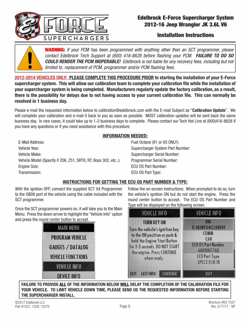
INSTRUCTIONS FOR GETTING THE ECU OS PART NUMBER & TYPE:With the ignition OFF, connect the supplied SCT X4 Programmer to the OBDII port of the vehicle using the cable included with the SCT programmer.
Once the SCT programmer powers on, it will take you to the Main Menu. Press the down arrow to highlight the “Vehicle Info” option and press the round center button to accept.
Follow the on-screen instructions. When prompted to do so, turn the vehicle’s ignition ON but do not start the engine. Press the round center button to accept. The ECU OS Part Number and Type will be displayed on the following screen.
FAILURE TO PROVIDE ALL OF THE INFORMATION BELOW WILL DELAY THE COMPLETION OF THE CALIBRATION FILE FOR YOUR VEHICLE. TO LIMIT VEHICLE DOWN TIME, PLEASE SEND US THE REQUESTED INFORMATION BEFORE STARTING THE SUPERCHARGER INSTALL.
WARNING: If your PCM has been programmed with anything other than an SCT programmer, please contact Edelbrock Tech Support at (800) 416-8628 before flashing your PCM. FAILURE TO DO SO COULD RENDER THE PCM INOPERABLE! Edelbrock is not liable for any recovery fees, including but not limited to, replacement of PCM, programmer and/or PCM flashing fees.
©2017 Edelbrock LLCPart #1527, 1528, 15270
Brochure #63-1527Rev. 5/17/17 - NP
Edelbrock E-Force Supercharger System 2012-16 Jeep Wrangler JK 3.6L V6
Installation Instructions
Page 9
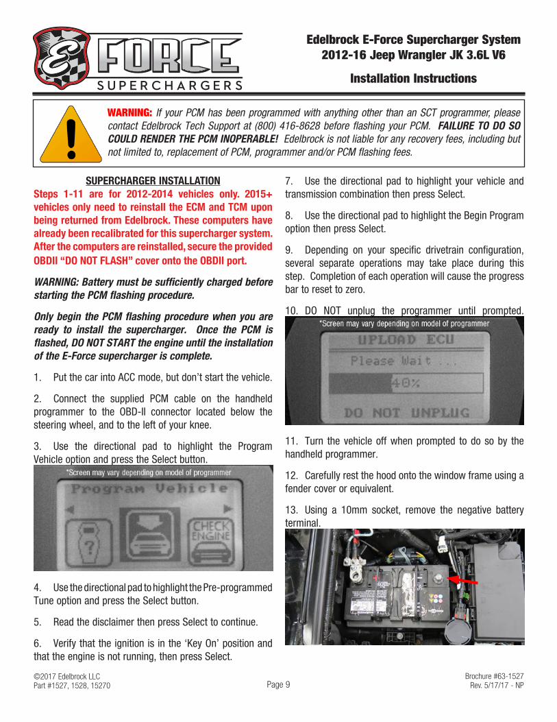
SUPERCHARGER INSTALLATIONSteps 1-11 are for 2012-2014 vehicles only. 2015+ vehicles only need to reinstall the ECM and TCM upon being returned from Edelbrock. These computers have already been recalibrated for this supercharger system. After the computers are reinstalled, secure the provided OBDII “DO NOT FLASH” cover onto the OBDII port.
WARNING: Battery must be sufficiently charged before starting the PCM flashing procedure.
Only begin the PCM flashing procedure when you are ready to install the supercharger. Once the PCM is flashed, DO NOT START the engine until the installation of the E-Force supercharger is complete.
1. Put the car into ACC mode, but don’t start the vehicle.
2. Connect the supplied PCM cable on the handheld programmer to the OBD-II connector located below the steering wheel, and to the left of your knee.
3. Use the directional pad to highlight the Program Vehicle option and press the Select button.
4. Use the directional pad to highlight the Pre-programmed Tune option and press the Select button.
5. Read the disclaimer then press Select to continue.
6. Verify that the ignition is in the ‘Key On’ position and that the engine is not running, then press Select.
7. Use the directional pad to highlight your vehicle and transmission combination then press Select.
8. Use the directional pad to highlight the Begin Program option then press Select.
9. Depending on your specific drivetrain configuration, several separate operations may take place during this step. Completion of each operation will cause the progress bar to reset to zero.
10. DO NOT unplug the programmer until prompted.
11. Turn the vehicle off when prompted to do so by the handheld programmer.
12. Carefully rest the hood onto the window frame using a fender cover or equivalent.
13. Using a 10mm socket, remove the negative battery terminal.
WARNING: If your PCM has been programmed with anything other than an SCT programmer, please contact Edelbrock Tech Support at (800) 416-8628 before flashing your PCM. FAILURE TO DO SO COULD RENDER THE PCM INOPERABLE! Edelbrock is not liable for any recovery fees, including but not limited to, replacement of PCM, programmer and/or PCM flashing fees.
©2017 Edelbrock LLCPart #1527, 1528, 15270
Brochure #63-1527Rev. 5/17/17 - NP
Edelbrock E-Force Supercharger System 2012-16 Jeep Wrangler JK 3.6L V6
Installation Instructions
Page 10
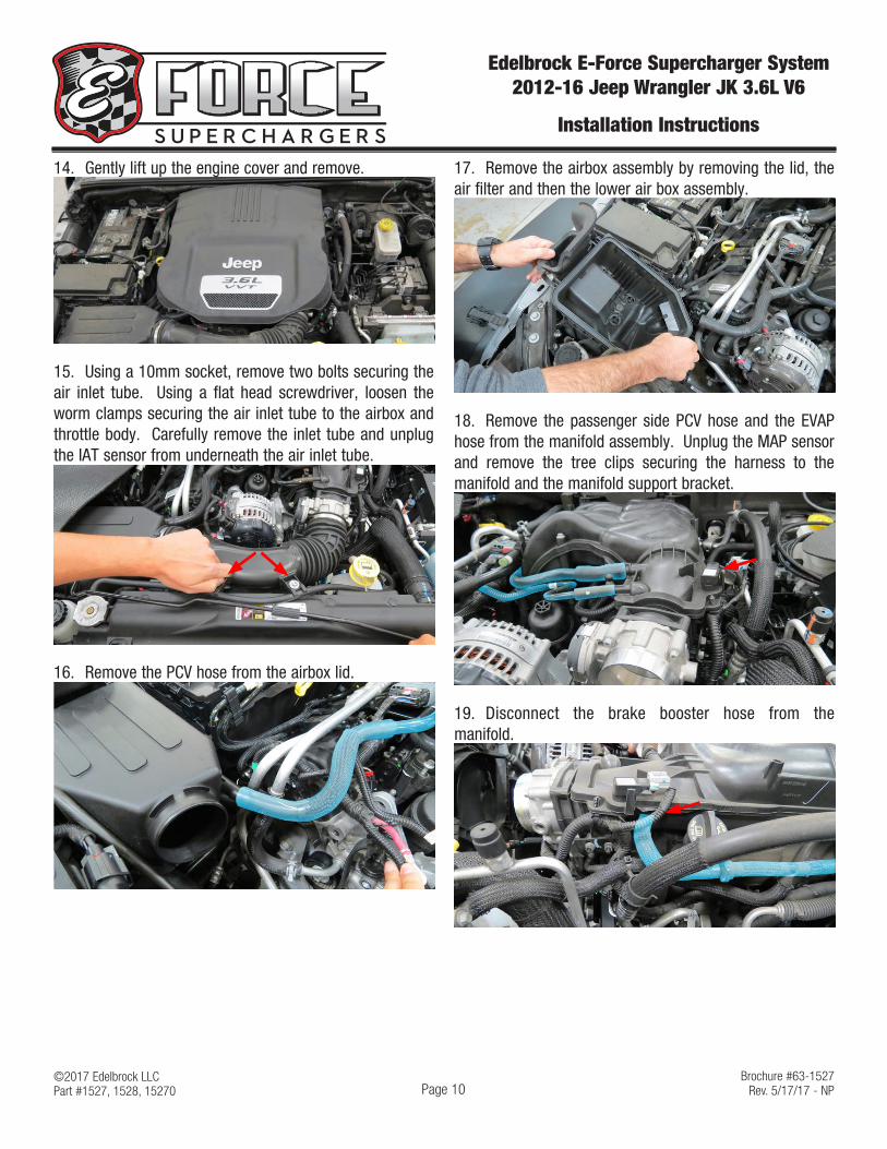
14. Gently lift up the engine cover and remove.
15. Using a 10mm socket, remove two bolts securing the air inlet tube. Using a flat head screwdriver, loosen the worm clamps securing the air inlet tube to the airbox and throttle body. Carefully remove the inlet tube and unplug the IAT sensor from underneath the air inlet tube.
16. Remove the PCV hose from the airbox lid.
17. Remove the airbox assembly by removing the lid, the air filter and then the lower air box assembly.
18. Remove the passenger side PCV hose and the EVAP hose from the manifold assembly. Unplug the MAP sensor and remove the tree clips securing the harness to the manifold and the manifold support bracket.
19. Disconnect the brake booster hose from the manifold.

©2017 Edelbrock LLCPart #1527, 1528, 15270
Brochure #63-1527Rev. 5/17/17 - NP
Edelbrock E-Force Supercharger System 2012-16 Jeep Wrangler JK 3.6L V6
Installation Instructions
Page 11
20. Unplug the electronic throttle body connector and remove the tree clip securing the harness to the manifold.
21. Using a 10mm socket, remove four (4) nuts from the front and rear manifold support brackets.
22. Using a panel puller, remove the engine harness from the passenger side manifold support bracket. Using a 10mm socket, remove two bolts securing the manifold to the support bracket.
23. Using a 10mm socket, remove two (2) nuts securing the coolant lines to the manifold support bracket.
24. Remove two (2) additional nuts securing the support bracket to the passenger side valve cover. Carefully remove the passenger side manifold support bracket.
25. Using a 1/2” breaker bar, rotate the belt tensioner clockwise and remove the belt. TIP: Tensioner is hydraulic and will require constant pressure to rotate.
26. Unplug the alternator voltage control connector and remove the alternator power cable using a 13mm socket.

©2017 Edelbrock LLCPart #1527, 1528, 15270
Brochure #63-1527Rev. 5/17/17 - NP
Edelbrock E-Force Supercharger System 2012-16 Jeep Wrangler JK 3.6L V6
Installation Instructions
Page 12
27. Using a 15mm socket, remove two (2) upper bolts securing the alternator to the engine. Remove two (2) lower bolts securing the alternator to the alternator bracket using a 13mm socket.
28. Remove the insulator from the manifold using a panel puller.
29. Using an 8mm socket, remove seven (7) bolts securing the upper manifold to the lower manifold.
30. Carefully lift up the upper manifold assembly and move it towards the front of the vehicle. Disconnect two (2) tree clips located on the rear of the manifold, then remove the manifold and set aside.
31. With a shop vac, clean the area around the lower manifold assembly as needed. This will prevent debris from getting into the intake ports.
32. Cover the port openings on the lower intake manifold with protective tape. Remove the insulator right of the intake manifold and set aside.
33. Disengage the blue locking clip on the fuel input line fitting and remove the fuel input line from the fuel rail.

©2017 Edelbrock LLCPart #1527, 1528, 15270
Brochure #63-1527Rev. 5/17/17 - NP
Edelbrock E-Force Supercharger System 2012-16 Jeep Wrangler JK 3.6L V6
Installation Instructions
Page 13
34. Lift up the red locking clips on the six (6) injector plugs and disconnect them from the fuel injectors.
35. Using an 8mm socket, remove eight (8) bolts securing the lower manifold to the cylinder heads.
36. Carefully remove the lower manifold and set aside.
37. Using a shop vac or clean shop rag, clean the cylinder head flanges and cover the ports with protective tape.
38. Using side cutters, remove the center wire tie securing the engine harness to the chassis. Using a cut off wheel, remove the mounting stud from this location. This is required as the wire tie/stud will make contact with the supercharger housing.
39. Using a 5/16” fuel line removal tool, remove the fuel input line from the factory hard line located behind the cylinder heads.
40. Install the 90° end of the supplied fuel feed line to the factory hard line.

©2017 Edelbrock LLCPart #1527, 1528, 15270
Brochure #63-1527Rev. 5/17/17 - NP
Edelbrock E-Force Supercharger System 2012-16 Jeep Wrangler JK 3.6L V6
Installation Instructions
Page 14
41. Drain about two quarts of coolant to avoid excess spillage during the next step. This can be done by removing the lower radiator hose or removing the petcock located towards the front, passenger side, of the radiator.
42. Unplug the oil cooler sensor connector located in between the cylinder head flanges. Using a 19mm deep socket, remove the oil cooler sensor.
43. Using pliers, carefully remove the factory oil cooler hose from the hard line and oil cooler. This hose must be replaced with the supplied hose to provide additional supercharger clearance.
44. Remove the sleeve from the factory oil cooler hose and install it onto the supplied oil cooler hose. Using the factory hose clamp, install the straight end of the hose onto the hard line. Using the supplied worm clamp from Bag #2, install the other end of the hose onto the oil cooler. Clean any coolant spillage before proceeding.
Worm Clamp
45. Apply Hi-Temp Thread Sealer to the sensor and reinstall the oil cooler sensor using a 19mm deep socket. Reconnect the oil sensor connector.
46. Remove the alternator bracket by removing the upper bolt with a 16mm socket and the lower bolt with a 13mm socket.
47. Using a vise, a 1/2” 24mm socket and a 3/8” 9mm deep socket, carefully remove two bushings from the factory alternator bracket. Tip: Channellock pliers can be used if you don’t have access to a vise.
48. Carefully install the bushings into the supplied FEAD bracket using a vise or equivalent. WARNING: DO NOT use a hammer as it may damage the bushings and/or FEAD bracket.
©2017 Edelbrock LLCPart #1527, 1528, 15270
Brochure #63-1527Rev. 5/17/17 - NP
Edelbrock E-Force Supercharger System 2012-16 Jeep Wrangler JK 3.6L V6
Installation Instructions
Page 15
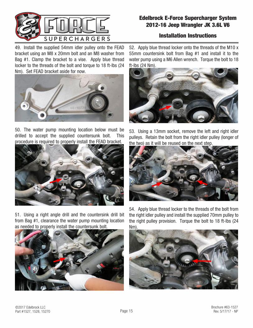
49. Install the supplied 54mm idler pulley onto the FEAD bracket using an M8 x 20mm bolt and an M8 washer from Bag #1. Clamp the bracket to a vise. Apply blue thread locker to the threads of the bolt and torque to 18 ft-lbs (24 Nm). Set FEAD bracket aside for now.
50. The water pump mounting location below must be drilled to accept the supplied countersunk bolt. This procedure is required to properly install the FEAD bracket.
51. Using a right angle drill and the countersink drill bit from Bag #1, clearance the water pump mounting location as needed to properly install the countersunk bolt.
52. Apply blue thread locker onto the threads of the M10 x 55mm countersink bolt from Bag #1 and install it to the water pump using a M6 Allen wrench. Torque the bolt to 18 ft-lbs (24 Nm).
53. Using a 13mm socket, remove the left and right idler pulleys. Retain the bolt from the right idler pulley (longer of the two) as it will be reused on the next step.
54. Apply blue thread locker to the threads of the bolt from the right idler pulley and install the supplied 70mm pulley to the right pulley provision. Torque the bolt to 18 ft-lbs (24 Nm).

©2017 Edelbrock LLCPart #1527, 1528, 15270
Brochure #63-1527Rev. 5/17/17 - NP
Edelbrock E-Force Supercharger System 2012-16 Jeep Wrangler JK 3.6L V6
Installation Instructions
Page 16
55. Feed the drive belt down towards the crank. Using the belt routing diagram, route the belt around the P/S, tensioner, crank, water pump and A/C.
56. Install the bracket to the provisions shown below using the hardware found in Bag #1. The lower-left hole will use the M8 x 75mm bolt. The lower-middle hole will use the M8 x 120mm bolt and the straight spacer. The upper-right bolt hole will use the M10 x 130mm bolt. Apply blue thread locker on each bolt and torque them all to 22 ft-lbs (30 Nm).
75mm
130mm
120mm & Spacer
Idler Provision
Alt. Provision
W/P Provision
57. Using two M8 x 30mm hex flange bolts from Bag #1, install the alternator onto the FEAD bracket. Using one of the longer factory alternator bolts, secure the alternator to the lower-left factory provision. Torque M8 bolts to 22 ft-lbs (30 Nm) and the stock bolt to 41 ft-lbs (55 Nm).
Stock Bolt
58. Position the alternator support bracket spacer, support bracket, and a M8 x 40mm hex flange bolt from Bag #1 onto the supplied 70mm pulley as shown. Apply blue thread locker to the threads of the bolt and loosely install it onto the upper FEAD provision as shown.
59. Position the drive belt in between the support bracket and pulley as shown. Using the M10 nut and M10 x 110mm bolt from Bag #1, secure the support bracket to the alternator. Torque the bolt to 41 ft-lbs (55 Nm). Fasten the idler pulley bolt and torque to 18 ft-lbs (24 Nm). Reconnect the alternator voltage control connector and the alternator power cable.

©2017 Edelbrock LLCPart #1527, 1528, 15270
Brochure #63-1527Rev. 5/17/17 - NP
Edelbrock E-Force Supercharger System 2012-16 Jeep Wrangler JK 3.6L V6
Installation Instructions
Page 17
60. Connect the IAT extension harness to the IAT sensor located on the rear of the lower manifold.
61. Remove the lower manifold gaskets from the factory lower manifold. Ensure the gasket are clean and dry of any oil residue. Inspect the o-rings for damage and replace as necessary (Jeep PN 05184331AC). Install the gaskets onto the supercharger lower manifold.
62. Remove the protective tape from the cylinder heads. Carefully lower the lower manifold assembly onto the cylinder heads. Apply blue thread locker onto the threads of the eight (8) M6 x 30mm hex bolts from Bag #3. Using a 10mm socket, secure the lower manifold to the cylinder heads with the M6 bolts. Use a circular torque sequence starting with the inner bolts and working outwards. Torque the bolts to 9 ft-lbs.
63. Apply o-ring lube to the supplied fuel fittings and install them onto the E-force fuel rails. The straight fittings are positioned on the rear of the fuel rails. The 180° fitting will go onto the passenger side rail and the plug on the driver side rail. Remove the metal retaining clips on the supplied fuel injectors. Gently lube the o-rings on the supplied fuel injectors and install them into the fuel rail provisions with the connector facing outwards.
Passenger
Driver
64. Install the 90° fitting on the supplied fuel crossover onto the rear driver side fuel rail fitting. Install the other end of the crossover onto the passenger side rail fitting.
Passenger Driver
90°
65. Apply o-ring lube to the lower injector o-rings. Align the fuel injectors with their provisions on the lower manifold and push down firmly to seat the injectors. Apply blue thread locker onto the threads of the M5 x 14mm bolts from Bag #3. Using the M5 bolts, secure the fuel rails to the lower manifold. Torque the bolts to 4 ft-lbs (5.42 Nm).
Plug
180°
Crossover
M5 x14

©2017 Edelbrock LLCPart #1527, 1528, 15270
Brochure #63-1527Rev. 5/17/17 - NP
Edelbrock E-Force Supercharger System 2012-16 Jeep Wrangler JK 3.6L V6
Installation Instructions
Page 18
66. Connect the injector connectors to the proper injectors. Position the fuel feed line around the passenger side fuel rail and connect it to the 180° fuel fitting.
67. Route the previously installed IAT extension towards the front of the vehicle, along the driver side valve cover, and connect it to the factory IAT connector.
68. Remove the passenger side PCV hose from the back of the passenger valve cover.
69. Install the supplied passenger side PCV hose to the rear of the passenger valve cover. Route hose around A/C lines. Hose will connect to supercharger later.
70. Apply o-ring lube to the o-ring on the supplied MAP sensor and carefully install it into the front provision on the intercooler adapter. Apply blue thread locker onto the threads of the M4 x 16mm bolts and secure the MAP sensor to the intercooler adapter using a 3mm Hex Key. Torque the bolts to 1.5 ft-lbs. DO NOT OVERTIGHTEN.
71. Using the hose clamps from Bag #2, secure the Manifold to Surge Tank hose to the inner intercooler barb and the Manifold to LTR hose to the outer intercooler barb.
Manifold to LTR
Manifold to Surge Tank
72. Position the Lower to Upper Manifold Gasket onto the lower manifold with the offset provision facing the front of the vehicle.
Front
©2017 Edelbrock LLCPart #1527, 1528, 15270
Brochure #63-1527Rev. 5/17/17 - NP
Edelbrock E-Force Supercharger System 2012-16 Jeep Wrangler JK 3.6L V6
Installation Instructions
Page 19
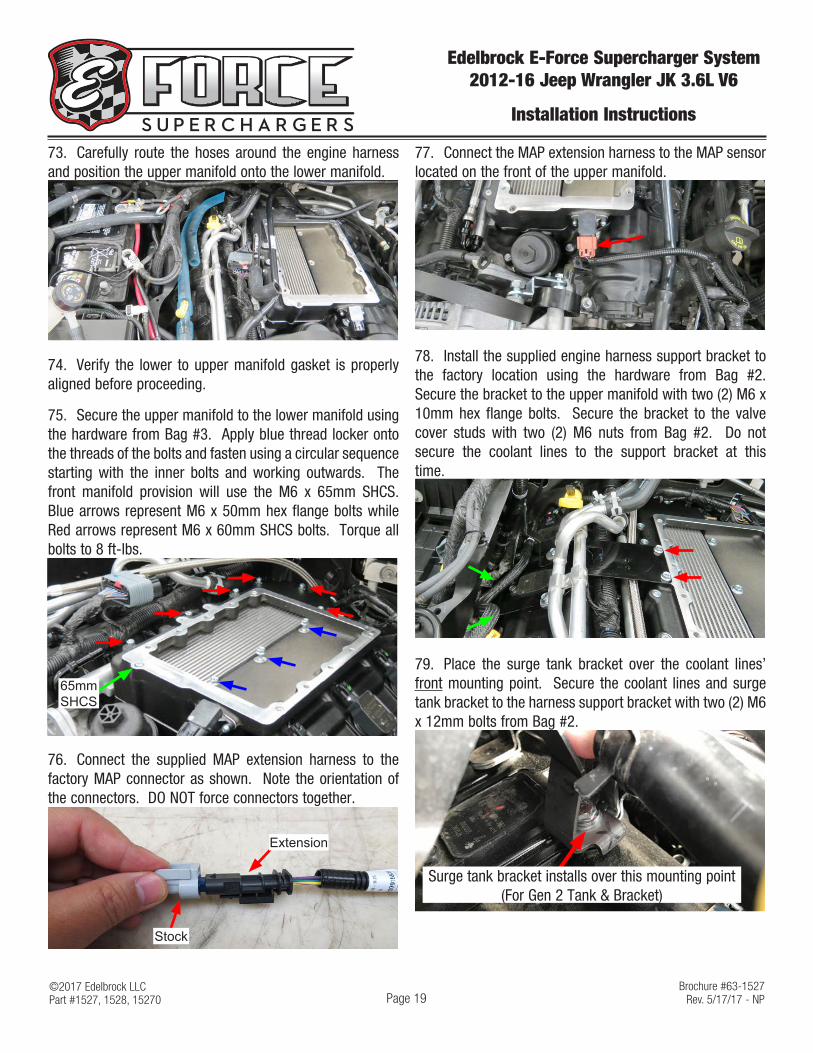
73. Carefully route the hoses around the engine harness and position the upper manifold onto the lower manifold.
74. Verify the lower to upper manifold gasket is properly aligned before proceeding.
75. Secure the upper manifold to the lower manifold using the hardware from Bag #3. Apply blue thread locker onto the threads of the bolts and fasten using a circular sequence starting with the inner bolts and working outwards. The front manifold provision will use the M6 x 65mm SHCS. Blue arrows represent M6 x 50mm hex flange bolts while Red arrows represent M6 x 60mm SHCS bolts. Torque all bolts to 8 ft-lbs.
65mm SHCS
76. Connect the supplied MAP extension harness to the factory MAP connector as shown. Note the orientation of the connectors. DO NOT force connectors together.
Extension
Stock
77. Connect the MAP extension harness to the MAP sensor located on the front of the upper manifold.
78. Install the supplied engine harness support bracket to the factory location using the hardware from Bag #2. Secure the bracket to the upper manifold with two (2) M6 x 10mm hex flange bolts. Secure the bracket to the valve cover studs with two (2) M6 nuts from Bag #2. Do not secure the coolant lines to the support bracket at this time.
79. Place the surge tank bracket over the coolant lines’ front mounting point. Secure the coolant lines and surge tank bracket to the harness support bracket with two (2) M6 x 12mm bolts from Bag #2.
Surge tank bracket installs over this mounting point (For Gen 2 Tank & Bracket)

©2017 Edelbrock LLCPart #1527, 1528, 15270
Brochure #63-1527Rev. 5/17/17 - NP
Edelbrock E-Force Supercharger System 2012-16 Jeep Wrangler JK 3.6L V6
Installation Instructions
Page 20
80. Connect the supplied bypass actuator hose to the barb located on the rear of the upper manifold. This will connect to the bypass actuator once the supercharger housing is installed.
81. Place the Upper Manifold to Supercharger gasket onto the upper manifold.
82. Carefully lower the supercharger onto the upper manifold and verify that the gasket is properly aligned. Apply blue thread locker onto the threads of the ten (10) M8 x 22 SHCS bolts from Bag #3. Install the bolts and fasten using a circular sequence starting with the inner bolts and working outwards. Torque the bolts to 8 ft-lbs.
83. Secure the supercharger nose to the factory manifold support bracket using two (2) M6 x 12mm hex bolts from Bag #3. TIP: Loosen the 2 bolts securing the bracket to the cylinder head if the holes do not line up properly.
84. Using a 1/2” breaker bar, rotate the hydraulic tensioner clockwise and finalize the installation of the drive belt.
85. Connect the previously installed actuator hose to the actuator barb.

©2017 Edelbrock LLCPart #1527, 1528, 15270
Brochure #63-1527Rev. 5/17/17 - NP
Edelbrock E-Force Supercharger System 2012-16 Jeep Wrangler JK 3.6L V6
Installation Instructions
Page 21
86. Remove the factory throttle body from the manifold using an 8mm socket.
87. Remove the factory throttle body gasket from the manifold and clean using a shop rag. Install the gasket onto the supercharger throttle body flange as shown.
88. Secure the throttle body to the supercharger nose using four (4) M6 x 40mm hex flange bolts from Bag #3. Reconnect the throttle body electronic connector.
89. Remove four (4) push pins securing the grill using a panel puller.
90. Carefully detach the grill and unplug the left and right signal lamp connectors. Remove the grill.
91. Remove the passenger side radiator shroud using a panel puller to remove two (2) tree clips securing the shroud. NOTE: Some cutting may be required to fully remove the shroud.
92. Loosely secure the upper driver side LTR bracket to the upper driver side condenser mounting location.
©2017 Edelbrock LLCPart #1527, 1528, 15270
Brochure #63-1527Rev. 5/17/17 - NP
Edelbrock E-Force Supercharger System 2012-16 Jeep Wrangler JK 3.6L V6
Installation Instructions
Page 22
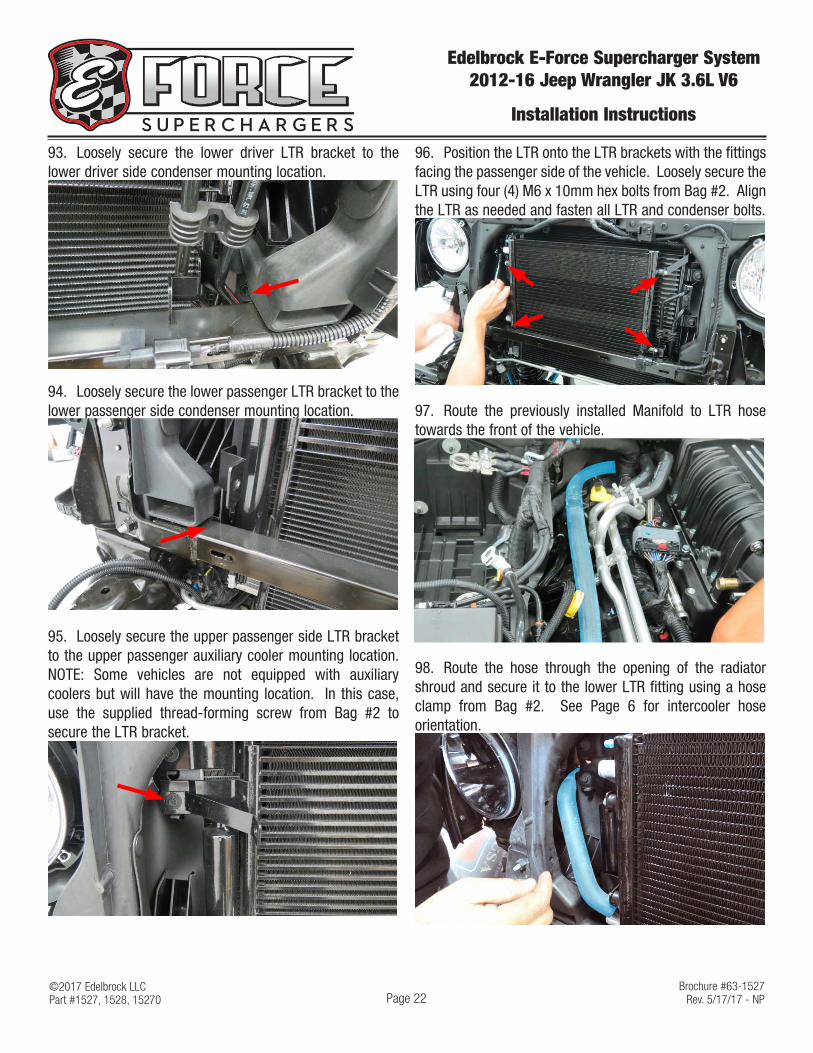
93. Loosely secure the lower driver LTR bracket to the lower driver side condenser mounting location.
94. Loosely secure the lower passenger LTR bracket to the lower passenger side condenser mounting location.
95. Loosely secure the upper passenger side LTR bracket to the upper passenger auxiliary cooler mounting location. NOTE: Some vehicles are not equipped with auxiliary coolers but will have the mounting location. In this case, use the supplied thread-forming screw from Bag #2 to secure the LTR bracket.
96. Position the LTR onto the LTR brackets with the fittings facing the passenger side of the vehicle. Loosely secure the LTR using four (4) M6 x 10mm hex bolts from Bag #2. Align the LTR as needed and fasten all LTR and condenser bolts.
97. Route the previously installed Manifold to LTR hose towards the front of the vehicle.
98. Route the hose through the opening of the radiator shroud and secure it to the lower LTR fitting using a hose clamp from Bag #2. See Page 6 for intercooler hose orientation.

©2017 Edelbrock LLCPart #1527, 1528, 15270
Brochure #63-1527Rev. 5/17/17 - NP
Edelbrock E-Force Supercharger System 2012-16 Jeep Wrangler JK 3.6L V6
Installation Instructions
Page 23
99. Secure the previously installed Surge Tank to Manifold hose to the surge tank (Gen 1 shown) using a hose clamp from Bag #2. Using two M6 x 10mm bolts from Bag #2, secure the surge tank to the surge tank bracket (Gen 2 Tank shown).
100. Install the water pump and water pump bracket onto the isolator. Clock the water pump so the outlet is pointing towards the water pump bracket.
Inlet
Outlet
Isolator
101. Using two (2) M8 washers and two (2) M8 x 20mm hex bolts from Bag #3, secure the water pump assembly to the inside of the passenger side chassis. Location is under the air box, in front of the engine mount. TIP: Bolts and washers will go through two opening adjacent to the strut tower. Be careful not to drop the bolts and washers in the frame
102. Using a hose clamp from Bag #2, secure the straight end of the Water Pump to Surge Tank hose to the surge tank. Route the other end down towards the water pump and secure it to the inlet barb.
103. Using a hose clamp from bag #2, secure the straight end of the Water Pump to LTR hose to the outlet barb on the water pump. Route the other end towards the LTR and secure to the upper LTR fitting with a hose clamp.
104. Reinstall the front grill using the factory push pins.
105. Using the thread-forming screw from Bag #2, secure the water pump harness relay to the provision below the radiator fan bolt.

©2017 Edelbrock LLCPart #1527, 1528, 15270
Brochure #63-1527Rev. 5/17/17 - NP
Edelbrock E-Force Supercharger System 2012-16 Jeep Wrangler JK 3.6L V6
Installation Instructions
Page 24
106. Connect the Constant (+12V) wire to the +12V terminal located inside the fuse box.
107. Using a 10mm socket, connect the Ground (-) wire on the water pump harness to the chassis ground adjacent to the power steering reservoir.
108. Using the factory fuse removal tool, remove the 20A fuse from the M6 slot (Outlet Power - Acc).
109. Install the factory 20A fuse into the fuse tap located on the water pump harness. Install the supplied 20A fuse into the other slot on the fuse tap. Insert the fuse tap into the M6 slot. Trim the fuse box as needed to prevent the wires from pinching when closing the fuse box lid.
110. Route the water pump power connector down towards the water pump and install it onto the water pump. Secure the water pump harness to existing harnesses as needed.
111. Remove the EVAP hose from the EVAP solenoid.
112. Connect the supplied EVAP hose to the EVAP solenoid. Route the hose under the A/C lines and connect it to the 8mm fitting towards the front of the supercharger.

©2017 Edelbrock LLCPart #1527, 1528, 15270
Brochure #63-1527Rev. 5/17/17 - NP
Edelbrock E-Force Supercharger System 2012-16 Jeep Wrangler JK 3.6L V6
Installation Instructions
Page 25
113. Connect the previously installed passenger side PCV hose to the rear barb on the supercharger nose.
114. Using a 1/4” drill bit, drill out the two rivets securing the air duct to the lower air box assembly. Remove the air duct. NOTE: We found the air duct to be very restrictive during testing. Removal is not required but is highly recommended.
115. Reinstall the airbox assembly using the supplied green filter.
116. Remove the rubber hose end attached to the molded plastic portion of the driver side PCV hose. Install the straight end of the supplied driver PCV hose onto the molded plastic tube.
117. Secure the driver side PCV hose to the factory airbox lid.
118. Reinstall the factory air intake tube using the factory hardware. Re-position the factory coolant over-flow hose onto the molded clamps on the intake tube.
119. Connect the brake booster hose to the barb on the supercharger inlet as shown.
120. Reconnect the battery terminals if not already done so.

©2017 Edelbrock LLCPart #1527, 1528, 15270
Brochure #63-1527Rev. 5/17/17 - NP
Edelbrock E-Force Supercharger System 2012-16 Jeep Wrangler JK 3.6L V6
Installation Instructions
Page 26
121. Fill the supercharger surge tank with a 50/50 coolant and water mixture. NOTE: Please see “How to Prime the Edelbrock E-Force Intercooler Systems” at the end of these instructions for detailed instructions.
122. Turn the ignition on but do not start the vehicle. Check for any fuel or coolant leaks. If leaks are present, shut the ignition off immediately and repair leaks before continuing.
123. This concludes the supercharger installation procedure. If you have not flashed the PCM do so by following Steps 1-13 at the beginning of these instructions; otherwise proceed to Step 125. DO NOT proceed if the PCM has not been flashed.
124. Start the engine and let it come up to operating temperature, then shut it off. Recheck and top off all fluid levels as necessary.
Maintenance Section: When replacing or servicing the belt, simply remove the straight spacer on the FEAD bracket installed in Step 56. Also remove the alternator support bracket installed in Step 58. Then feed the belt through the open gaps in the bracket to replace the belt as necessary.

How to Prime the Edelbrock E-Force Intercooler Systems.
The electric water pump used on this Edelbrock E-Force Supercharger System has a built-in micro-processor that will vary pump cycle speed when air bubbles are present in the system. If a significant amount of air is trapped in the system, the pump may cycle at a slower speed and pulsations are likely to occur resulting in poor cooling performance.
For the best result, it is highly recommended to use a Radiator Cooling System Vacuum Purge and Refill Kit to properly evacuate the air from the intercooler system before filling with a 50/50 mixture of coolant and distilled water. If one is not available, the following procedure will be adequate.
1. Using the Lisle 24680 Spill-Free Funnel, or equivalent, secure the appropriate filler neck adapter to the surge tank.
2. Attach the funnel and fill with a 50/50 mixture of coolant and distilled water until the funnel is half full.
3. Turn the ignition to the ON position and listen for the pump’s electric motor to cycle. Air bubbles will begin to purge from the system as the coolant level drops. Add coolant to the funnel as necessary. NOTE: Do NOT let the coolant level in the funnel run empty as this may introduce air into the system.
4. To build more pressure in the intercooler system, try squeezing the intercooler hoses while the pump is cycling. Building pressure in the system will help purge the trapped air from the intercooler system.
5. Cycle the ignition OFF and wait a few seconds for the pump to come to a stop.
6. Cycle the ignition ON again and repeat until the sound of the electric pump is continuous without any pulsation. NOTE: During water pump start-up, it is normal for a slight pulsation to occur. Once the pump has reached its maximum cycle speed, no pulsations should be present.
7. Periodically inspect the water pump flow after a few drive cycles and re-fill the intercooler system as necessary.
8. Several drive cycles may be required to completely purge the air from the intercooler system. During a drive cycle, the intercooler system will build up pressure as the supercharger temperature increases. Any residual air trapped in the system will gradually bleed out of the surge tank as the system reaches a pressure above 5psi.
WARNING: Always avoid removing the surge tank cap when the engine is hot. The hot coolant is under pressure and may spray out causing burns.