
EDACS SYSTEM MANAGER - Repeater · PDF fileF6 EXIT Press F6 to return to a main category...
102
LBI-38984 Mobile Communications EDACS SYSTEM MANAGER (Enhanced Digital Access Communications System) User’s Guide For Version 3.XX (Group 3) User’s Guide
Transcript of EDACS SYSTEM MANAGER - Repeater · PDF fileF6 EXIT Press F6 to return to a main category...

LBI-38984
Mobile Communications
EDACSSYSTEM MANAGER(Enhanced Digital Access Communications System)
User’s Guide For Version 3.XX (Group 3)
User’s Guide

Copyright© November 1993, Ericsson GE Mobile Communications Inc.
TABLE OF CONTENTS
Page
Section/Paragraph
INTRODUCTION . . . . . . . . . . . . . . . . . . . . . . . . . . . . . . . . . . . . . . . . . . . . . . . . . . 4
GENERAL . . . . . . . . . . . . . . . . . . . . . . . . . . . . . . . . . . . . . . . . . . . . . . . . . . . 4
CONFIGURATIONS . . . . . . . . . . . . . . . . . . . . . . . . . . . . . . . . . . . . . . . . . . . . . . 4
KEYBOARD FUNCTIONS . . . . . . . . . . . . . . . . . . . . . . . . . . . . . . . . . . . . . . . . . . . . . 6
GETTING STARTED . . . . . . . . . . . . . . . . . . . . . . . . . . . . . . . . . . . . . . . . . . . . . . . . . 8
LOGIN . . . . . . . . . . . . . . . . . . . . . . . . . . . . . . . . . . . . . . . . . . . . . . . . . . . . . . 8
RECORDS . . . . . . . . . . . . . . . . . . . . . . . . . . . . . . . . . . . . . . . . . . . . . . . . . . . . 9
MENU SELECTIONS . . . . . . . . . . . . . . . . . . . . . . . . . . . . . . . . . . . . . . . . . . . . . 10
ENDING A SESSION . . . . . . . . . . . . . . . . . . . . . . . . . . . . . . . . . . . . . . . . . . . . . . 10
USER MENU . . . . . . . . . . . . . . . . . . . . . . . . . . . . . . . . . . . . . . . . . . . . . . . . . . . . . 10
1) DATABASE MAINTENANCE . . . . . . . . . . . . . . . . . . . . . . . . . . . . . . . . . . . . . . . 12
0) SITE/DEVICE DEFINITION . . . . . . . . . . . . . . . . . . . . . . . . . . . . . . . . . . . 121) LOGICAL UNIT DEFINITION . . . . . . . . . . . . . . . . . . . . . . . . . . . . . . . . . . 182) GROUP IDENTIFICATION . . . . . . . . . . . . . . . . . . . . . . . . . . . . . . . . . . . . 223) ROTARY DEFINITION . . . . . . . . . . . . . . . . . . . . . . . . . . . . . . . . . . . . . . 254) LINE DEFINITION . . . . . . . . . . . . . . . . . . . . . . . . . . . . . . . . . . . . . . . . 27 5) TOLL CALL RESTRICTIONS . . . . . . . . . . . . . . . . . . . . . . . . . . . . . . . . . . 296) ACU PARAMETERS . . . . . . . . . . . . . . . . . . . . . . . . . . . . . . . . . . . . . . . . 317) CONSOLE DEFINITION . . . . . . . . . . . . . . . . . . . . . . . . . . . . . . . . . . . . . 31
2) SITE RECONFIGURATION . . . . . . . . . . . . . . . . . . . . . . . . . . . . . . . . . . . . . . . . 33
0) CHANNEL . . . . . . . . . . . . . . . . . . . . . . . . . . . . . . . . . . . . . . . . . . . . . 331) CALL PARAMETERS . . . . . . . . . . . . . . . . . . . . . . . . . . . . . . . . . . . . . . . 342) TEST PARAMETERS . . . . . . . . . . . . . . . . . . . . . . . . . . . . . . . . . . . . . . . 373) MISCELLANEOUS PARAMETERS . . . . . . . . . . . . . . . . . . . . . . . . . . . . . . . 374) RELAY . . . . . . . . . . . . . . . . . . . . . . . . . . . . . . . . . . . . . . . . . . . . . . . 38
3) DEVICE COMMUNICATION . . . . . . . . . . . . . . . . . . . . . . . . . . . . . . . . . . . . . . . 38
0) DATABASE UPLOAD . . . . . . . . . . . . . . . . . . . . . . . . . . . . . . . . . . . . . . . 381) ACTIVITY DOWNLOAD . . . . . . . . . . . . . . . . . . . . . . . . . . . . . . . . . . . . . 412) SITE MONITOR . . . . . . . . . . . . . . . . . . . . . . . . . . . . . . . . . . . . . . . . . . 42
LBI-38984
2

Page
4) ALARM CONTROL . . . . . . . . . . . . . . . . . . . . . . . . . . . . . . . . . . . . . . . . . . . . . 43
0) ALARM CONTROL DISPLAY . . . . . . . . . . . . . . . . . . . . . . . . . . . . . . . . . . 431) RELAY TRIGGER DEFINITIONS . . . . . . . . . . . . . . . . . . . . . . . . . . . . . . . . 45
5) RADIO CONTROL . . . . . . . . . . . . . . . . . . . . . . . . . . . . . . . . . . . . . . . . . . . . . 48
0) UNIT ENABLE/DISABLE . . . . . . . . . . . . . . . . . . . . . . . . . . . . . . . . . . . . . 481) DYNAMIC REGROUP . . . . . . . . . . . . . . . . . . . . . . . . . . . . . . . . . . . . . . 502) MULTISITE UNIT LOCATION . . . . . . . . . . . . . . . . . . . . . . . . . . . . . . . . . . 533) MULTISITE GROUP LOCATION . . . . . . . . . . . . . . . . . . . . . . . . . . . . . . . . . 55
6) REPORTS . . . . . . . . . . . . . . . . . . . . . . . . . . . . . . . . . . . . . . . . . . . . . . . . . . . 58
0) DEVICE REPORT . . . . . . . . . . . . . . . . . . . . . . . . . . . . . . . . . . . . . . . . . 581) LOGICAL UNIT . . . . . . . . . . . . . . . . . . . . . . . . . . . . . . . . . . . . . . . . . . 582) GROUP . . . . . . . . . . . . . . . . . . . . . . . . . . . . . . . . . . . . . . . . . . . . . . . 623) ACTIVITY DETAIL . . . . . . . . . . . . . . . . . . . . . . . . . . . . . . . . . . . . . . . . 644) ACTIVITY SUMMARY . . . . . . . . . . . . . . . . . . . . . . . . . . . . . . . . . . . . . . 665) ALARM . . . . . . . . . . . . . . . . . . . . . . . . . . . . . . . . . . . . . . . . . . . . . . . 686) CHANNEL STATISTICS . . . . . . . . . . . . . . . . . . . . . . . . . . . . . . . . . . . . . . 697) SITE STATISTICS . . . . . . . . . . . . . . . . . . . . . . . . . . . . . . . . . . . . . . . . . 708) EVENT LOG DISPLAY . . . . . . . . . . . . . . . . . . . . . . . . . . . . . . . . . . . . . . 719) REPORTS MANAGER . . . . . . . . . . . . . . . . . . . . . . . . . . . . . . . . . . . . . . . 72
7) SYSTEM MAINTENANCE . . . . . . . . . . . . . . . . . . . . . . . . . . . . . . . . . . . . . . . . . 73
0) AGENCY PARTITION TABLE . . . . . . . . . . . . . . . . . . . . . . . . . . . . . . . . . . 731) USER ACCOUNT MAINTENANCE . . . . . . . . . . . . . . . . . . . . . . . . . . . . . . . 752) DATABASE ARCHIVE . . . . . . . . . . . . . . . . . . . . . . . . . . . . . . . . . . . . . . 803) DATABASE RETRIEVAL . . . . . . . . . . . . . . . . . . . . . . . . . . . . . . . . . . . . . 814) ACTIVITY ARCHIVE . . . . . . . . . . . . . . . . . . . . . . . . . . . . . . . . . . . . . . . 825) ACTIVITY RETRIEVAL . . . . . . . . . . . . . . . . . . . . . . . . . . . . . . . . . . . . . . 836) SYSTEM BACKUP . . . . . . . . . . . . . . . . . . . . . . . . . . . . . . . . . . . . . . . . 847) DISK SPACE MANAGER . . . . . . . . . . . . . . . . . . . . . . . . . . . . . . . . . . . . . 85
APPENDIX A - MONITOR DISPLAY MESSAGES AND STATUS CHANGES . . . . . . . . . . . . . . A-1
APPENDIX B - SYSTEM MANAGER MESSAGES . . . . . . . . . . . . . . . . . . . . . . . . . . . . . B-1
APPENDIX C -AUTOMATIC CONTROL CHANNEL ROTATION . . . . . . . . . . . . . . . . . . . . . C-1
APPENDIX D - ALARM REPORT DESCRIPTIONS . . . . . . . . . . . . . . . . . . . . . . . . . . . . . D-1
APPENDIX E - GLOSSARY . . . . . . . . . . . . . . . . . . . . . . . . . . . . . . . . . . . . . . . . . . E-1
LBI-38984
3

INTRODUCTION
GENERAL
This manual is provided as a reference guide for supervisory level users of the EDACS (Enhanced Digital Access Commu-nications System) System Manager operating with Version 3.XX software. The manual contains information on the keyboardfunctions, log in/log off procedures, as well as a brief explanation of the different configurations available. A representation ofeach menu and help information for each screen is also provided.
A separate manual is available for the Installation/SetUp procedures. Refer to LBI-38703.
CONFIGURATIONS
There are five different configurations available, depending on system requirements. All of the configurations require aVAX 3100 computer from Digital Equipment Corporation (DEC) with the necessary RAM, hard drives and peripherals. Figure1 provides a hardware/software matrix of each system configuration and equipment supplied.
LBI-38984
4

Sof
twar
e O
ptio
ns
FU
LL F
EAT
UR
ES
All
Cor
e an
d M
id F
eatu
res
Plu
s:S
yste
m A
ssig
ned
Con
sole
ID’s
,D
ynam
ic R
egr
oupi
ng,
Mul
ti-si
te U
nit L
ocat
ion,
Mul
ti-si
te G
roup
Loc
atio
n
Sin
gle
site
with
full
softw
are
optio
ns.
Mul
tisite
con
figur
atio
n w
ith fu
llso
ftwar
e fe
atu
res
Larg
er m
ultis
ite c
onfig
urat
ion
full
softw
are
fea
ture
s
Larg
er m
ultis
ite c
onfig
urat
ion
full
softw
are
fea
ture
s
Larg
est m
ultis
ite c
onfig
urat
ion
with
full
soft
war
e fe
atu
res.
Any
hard
war
e co
nfig
urat
ion
larg
er
than
this
is a
spe
cia
l.
Fig
ure
1 -
Sys
tem
Ma
nage
r P
rodu
ct O
fferin
g M
atri
x
MID
FE
ATU
RE
SA
larm
Con
trol
& R
ela
y T
rigge
rD
ispl
ay, F
ull A
ctiv
ity D
eta
il &
Sum
mar
y, A
larm
Rep
orts
, Cha
nnel
and
Site
Sta
tistic
s, A
ctiv
ity A
rchi
vean
d R
etri
eval
Uni
t Ena
ble/
Dis
able
,D
isk
Man
ager
Sin
gle
site
with
mor
e c
ompl
ete
softw
are
optio
ns la
ckin
g on
lydy
nam
ic r
egr
oup
(no
need
for
mul
tisite
loca
tion
for
sing
le s
iteap
plic
atio
n).
Mul
tisite
con
figur
atio
n w
ith m
ore
com
ple
te s
oftw
are
fea
ture
s
Larg
er m
ultis
ite c
onfig
urat
ion
with
mor
e co
mpl
ete
sof
twar
e fe
atur
es
Larg
e m
ultis
ite c
onfig
urat
ion
with
mor
e co
mpl
ete
sof
twar
e fe
atur
es
Larg
est m
ultis
ite c
onfig
urat
ion
with
mor
e co
mpl
ete
sof
twar
efe
atur
es. A
ny h
ardw
are
conf
igur
atio
n la
rger
than
this
is a
spec
ial.
CO
RE
FE
ATU
RE
SS
ite, U
nit,
Gro
up D
efin
ition
s, T
oll
Ca
ll R
estr
ictio
ns, C
hann
el C
all
Test
Rec
onfig
. Site
, Uni
t, G
roup
Re
port
s, R
epor
t Man
ager
, Eve
ntLo
g, S
ite M
onito
r, D
atab
ase
Arc
hive
and
Ret
rieva
l, S
yste
mB
ack
up
Sim
ple
conf
igur
atio
n su
ppor
ting
asi
ngle
site
with
min
imal
sof
twar
efe
atur
es
Mul
tisite
con
figur
atio
n w
ithm
inim
al s
oftw
are
feat
ures
Larg
er m
ultis
ite c
onfig
urat
ion,
min
imal
sof
twar
e fe
atur
es
Larg
e m
ultis
ite c
onfig
urat
ion,
min
imal
sof
twar
e fe
atur
es
Larg
est m
ultis
ite c
onfig
urat
ion,
min
imal
sof
twa
re fe
atur
es.
Any
hard
war
e co
nfig
urat
ion
larg
er
than
this
is a
spe
cia
l.
A1
0
M
SC
1
S
ites
1
T
erm
inal
A2
1
M
SC
5
S
ites
1-2
T
erm
ina
ls
A3
1
M
SC
10
S
ites
1-5
T
erm
inal
s
A4
1
M
SC
20
S
ites
1-11
Te
rmin
als
A5
1
M
SC
30
S
ites
1-17
Te
rmin
als
HARDWARE OPTIONS
LBI-38984
5

KEYBOARD FUNCTIONS
The System Manager uses a standard DEC keyboard. This allows the user to access all of the menus, and to enter or changeinformation on the site/location screens. The various menus and screens can be easily accessed using the number or cursor (ar-row) keys. Any changes, updates or other information entered can be saved, cleared or deleted by using the various function(F) keys. The keyboard layout is shown in Figure 2.
A brief explanation of the DEC keyboard functions is shown below. Unique functions of some of the (F) keys are definedwith the appropriate screens.
RETURN Enters information into a field and causes the cursor to move to the next field.
[Up Arrow] Moves to the previous field (also decreases numbers in the Enter Menu Item field).
[Right Arrow] Moves the cursor right.
[Left Arrow] Moves the cursor left.
[Down Arrow] Moves to the next field (also increases numbers in the Enter Menu Item field).
Help Displays help information for the current screen.
F9 Pressing F9 toggles the function key definitions for F1 through F20 at the bottom of each screen. Only thekeys used for each screen are displayed.
Ctrl W Redraws the screen.
Figure 2- System Manager DEC Keyboard
LBI-38984
6

F6 EXIT Press F6 to return to a main category screen.
F7 Logs off the system manager from the Main Menu.
Do Performs a save or change, (i.e., writes to the Database or Site).
Find & Select Work together to show and select other sites from any working menu or screen. They also provide the DeviceNumber and Device Type of a particular site when in any working menu except the User Menu. In addition,the Find and Select functions do not operate in screens not supported by optional hardware or software.
Figure 3 shows the External Device screen 1:4 with site 1 selected. To access any other site record while inscreen 1:4, press the Find key. The screen displays the Select Device pop-up menu (see Figure 4). Then usethe down arrow to highlight the desired site. An asterisk (* ) shows to the left of the selected site number. Sim-ply press the Select key to switch to screen 1:4 and the selected site record.
To switch back to your original screen or another site, press the Find key and move the asterisk to the desiredsite, and press Select. You will then switch to the selected site screen.
Figure 3 - External Device Menu 1:4
LBI-38984
7

GETTING STARTED
LOGIN
Once your terminal is turned on, the System Manager Login screen is displayed with the cursor blinking at the USER-NAME field (see Figure 5). If the Login screen does not appear, press Return again. If the screen still does not appear, checkthe terminal setup (see LBI-38703).
When you first log on the System Manager, your user name is EGESYSMGR and your password is EGESYSMGR.
To protect the security of the system, use the User Account Maintenance function to change your password after the firstlogin. A 12-character password is recommended for maximum security.
NOTE
EDACS System Manager
USERNAME:PASSWORD:
Figure 5 - Login
Figure 4 - Menu 1:4 With Selected Devices Window
LBI-38984
8

Login the System Manager as follows:
1. Type in your USERNAME and press Return.
2. Type in your PASSWORD and press Return.
3. The User Menu now appears.
RECORDS
A record is a collection of all of the configuration data from all the screens in a Main Menu selection (i.e., four screens forSite configuration). The individual fields on the screens are the attributes within that record.
To Create a Record:
1. Enter a new Site, LID, or GID Number. The word CREATE appears in the upper right corner of the screen.
2. Enter all required fields. These are identical to the required fields in the screens described in the following para-graphs.
3. Press the Do key to save the screen.
To Locate a Record:
1. Enter the Site, LID, or GID Number or Site, Unit, or Group Name.
2. Press Return.
To Modify an Existing Record:
1. Locate the record. The word MODIFY appears in the upper right corner of the screen.
2. Make desired changes on the screen.
3. Press the DO key to save the screen.
To Delete a Record:
1. Locate the record. The word MODIFY appears in the upper right corner of the screen.
2. Press F8 to delete all entries from the fields on the screen.
3. Press F8 again to confirm the delete operation.
User Tip: When creating or modifying a record, and before the screen is saved, you can delete all of your entries bypressing F10. This is a quick way to clear the fields if you want to start over.
If the requested record name cannot be found, the closest record in alphanumeric order is displayed.
NOTE
LBI-38984
9

MENU SELECTIONS
All of the categories containing the site and system parameters that can be created or modified are contained in the UserMenu. The user Menu contains two windows, with each window containing a list of numbered functions. These functions arenormally accessed when the system is first put on-line, and are used only occasionally after the initial system configuration. Atypical User Menu screen is shown in Figure 6.
The User Menu functions allow you to setup selected system parameters. These parameters control the operating parame-ters of each of the radio units at the different sites/locations; determining, 1) how each operates in the system, 2) how they in-teract with each other, and 3) how the system handles different operating events. More details on the User Menu are containedin the USER MENU section below.
The cursor present in the User Main Menu controls selections. Functions can be accessed from the prompt either by typingin the function number and pressing the RETURN or by selecting highlighted functions with up or down arrow keys and thenpressing the RETURN key. If you are very familiar with the System Manager, the fastest method is to type the function num-ber, then press the RETURN key.
ENDING A SESSION
After you have finished using the System Manager, you should exit to the System Manager Login screen. This terminatesthe session and prevents unauthorized use of the System Manager. Log off the System Manager as follows:
1. If the User Menu is not displayed, exit the current screen and return to the Main Menu.
2. Then press F7 (EXIT from System Manager).
USER MENU
The User Menu screen is the first screen you see after Login. All of the Menu Selections listed under Main Categories andDatabase Maintenance screens are initially displayed in this menu.
The User Menu is divided into two major windows consisting of the Selected Menu Item and the Menu Selections. TheSelected Menu Item window is the command window that allows you to select the different screens from the Menu Selectionscategories. The Menu Selections window highlights the selected categories and acts as a reference guide. The complete UserMenu is shown in Figure 6 with: 1) Database Maintenance selected (highlighted) in the Main Categories window, and with 0)Site / Device Definition selected in the Database Maintenance window.
The Menu Selections window is divided into two additional windows as shown in Figure 6. The window on the left istitled Main Categories, and shows all of the functional areas that the System Manager controls. The window to the right of theMain Categories window is titled the same as the selected (highlighted) category in the Main Categories window and displayssubselections (functions).
It is recommended that you log off the System Manager when you are away from the terminal, or at the end of a session.This helps prevent unauthorized use of the System Manager.
NOTE
LBI-38984
10

The cursor remains at the Enter Menu Item prompt (two-digit number) in the user menu. Functions can be accessed fromthe prompt either by typing in the function number and pressing the RETURN or by selecting the highlighted function with upor down arrow keys and then pressing the RETURN key. If you are very familiar with the System Manager, the fastest methodis to type the function number, then press the RETURN key.
When the cursor is resting on the "tens" digit at the Enter Menu Item prompt, you can use the up and down arrow keys tochange the digit and move the highlighted selection in the Main Categories window accordingly. You will notice that the win-dow on the right changes, displaying subselections for each category selected. When the cursor is resting on the "ones" digitat the Enter Menu Item prompt, the up and down arrow keys change that digit and move the highlighted selection in the Data-base Maintenance window accordingly. The left and right arrows are used to switch between the "tens", and "ones" digit.When the desired category and function are highlighted, press the RETURN key to access that function.
For example, press the down arrow until "6) Reports" is highlighted in the Main Categories window. You will notice thatthe window on the right is entitled "Reports". Move the cursor to the "ones" digit by pressing the right arrow. Press the downarrow until "2) Group" is highlighted in the Reports window. By pressing the RETURN key, you will access the first screenfor the group ID reports. Press F6 to return to the User Menu.
Each of the functions has from to one to nine additional numbered screens containing the System Manager field definitionsand parameters. The first of these screens is accessed by pressing Return when the desired function is selected in the EnterMenu Item field. Additional field definition screens, if present, are accessed by pressing the Next Screen key.
Each of the user screens and menu selections are explained in this manual. Each screen has an explanation telling whattype of information must be entered in each field with the system defaults, where applicable. All information in the field defi-nition screens must be entered for System Manager to accept and save the information.
To assist in the explanation of the various screens, the following screen descriptions show the Main Categories window se-lections as centered headings preceded by digits 1) through 7) as shown below [i.e., 1) DATABASE MAINTENANCE]. TheDatabase Maintenance (or other function) window selections are shown as headings on the left of the page preceded by digits0) through 6) [i.e., 0) Site/Device Definition].
Figure 6 - User Menu Screen
LBI-38984
11

1) DATABASE MAINTENANCEThere are seven categories shown in the Database Maintenance screen. These categories are listed in the Database Mainte-
nance window as 0) through 6). Each of these categories has one or more field definition screens. The first field definitionscreen (Select Screen) is accessed by pressing the Return key. Additional screens require pressing the Next Screen key.
0) SITE/DEVICE DEFINITION
The Site/Device Definition under the Database Maintenance main category, item "10", defines the default channel configu-rations for each site. The function also defines the various site and device parameters. These default values are used by the SiteController when first powered up, and remain in effect until the desired parameter changes are made to the database for eachindividual system.
When the Site/Device Definition function has been selected, (i.e., screen number 10 shown in Figure 7), pressing Returncauses display of the External Device Definition screen. There are four External Device Definition screens, numbered 1:4through 4:4. The configuration screens are :
• 1:4 - Channel Configuration
• 2:4 - Site Parameters
• 3:4 - Site Test Parameters
• 4:4 - Communications Parameters
Each of these screens contains two windows; a Selected Device window and a Parameters window. The cursor appearsfirst in the Selected Device window at the device (site) number prompt. Typing in the device number displays the Parameters
window (with the screen number) just below the Selected Device window.
A typical view of the User Menu plus the Selected Device and Unit Identification screens 1:4 through 4:4 are shown inFigure 7.
Selected Device
Device Number: Numeric designation of a site number (1-32), or a device (33-64).
Device Type: There are different screens for different device types. The screens shown are for site controllers. Thereare also screens for MultiSite Controllers (MSCs).
Device Name: Up to an eight-character alphanumeric site name that must be unique for all devices.
Screen 1:4 Channel Configuration
RF: Designates working channels and a control channel. Enter C in one position (only) to designate the con-trol channel. Enter Y to designate (all) working channels. Enter N (default) under all unused channels.
All of the Selected Device screens as well as the function key definitions at the bottom of each Site/Device Definitionscreen are identical for screens 1:4 through 4:4.
NOTE
LBI-38984
12

Interconnect: Designates channels equipped to handle telephone interconnect. Enter Y under (all) channels equippedfor telephone interconnect, or N (default) under unused channels and channels not equipped for intercon-nect.
Digitized: Voice
Designates channels equipped to handle digitized voice transmissions. Enter Y under channels equippedfor digitized voice or N (default) under unused or non-equipped channels.
Data: Designates channels equipped to handle data transmissions from mobile data terminals. Enter Y underchannels equipped to handle data transmissions or N (default) under unused channels and channels notequipped for data transfers.
Partition 2: Assigns a set of channels for special assignment to selected radios and groups. Enter Y for a test chan-nel, or N (default) for a normal partition.
Allowed CC: Designates a channel with control channel capability. Enter Y for control channel capability, or N (de-fault) to disable (prohibit control channel use).
Wide Area: Enter a Y on the channel configuration to allow this channel to be used in a multisite configuration. Thisallows a "Wide Area" of coverage. Enter a N to disable Wide Area communication for this channel.
Downlink: Designates a channel number to be used as a redundant downlink to the Multisite coordinator or console.Channel 26 is always assumed to be the primary downlink (default). Enter Y to enable.
Relay on: Relay number headings 1-8 for the relay state fields correspond to the eight control output relays at theTest And Alarm Unit (TAU). Enter N (default) under the number of the relays you want to remain in thereset state. Enter Y under the number of the relays you want set when a RECONFIGURATION requestis submitted to the Site Controller.
Screen 2:4 - Site Parameters
Press Next Screen to access the Site Parameters screen from the Channel Configuration screen.
The Site Parameters screen contains the Channel Assignment Parameters in the first column, and Miscellaneous Parame-ters in the second column. A typical example of Site Parameters Screen 2:4 is shown in Figure 7.
Channel Assignment Parameters
Transmission Conv Limit: Sets the transmission conversation time limit for transmission trunked calls. Time is ex-pressed in seconds (x10) with a default setting of 30 (300 seconds or 5 minutes).
Message Conv Limit: Sets the conversation time limit for message trunked conversations. Time is expressed inseconds (x10) with a default setting of 30 (300 seconds or 5 minutes).
Interconnect Hang Time: The time between an unkey command and channel drop for telephone interconnect calls inseconds. Hang time is expressed in seconds with a default of 30.
LBI-38984
13

NOTE: The "Selected Device" section of the display remains on the screen when the Next Screen keyis used to display 2:4, 3:4, & 4:4 (see Figure 7A)
Figure 7 - Database Maintenance: Site Device Definition (Screen 10) (Includes External Device Definition screen 1:4)
LBI-38984
14

Figure 7A - Database Maintenance: Site Device Definition (Screen 10)(Includes External Device Definition screens 2:4 through 4:4)
LBI-38984
15

Emergency Hang Time: The time between an unkey command and a channel drop for emergency calls. Hang time isexpressed in seconds with a default of 2.
Rotate Assignments: Enter Y (default) if you want the working channel assignment rotated by the system. EnterN to prevent automatic working channel rotation.
Assign Chan Ascending: This field sets the order in which the Site Controller makes working channel assignments.Enter Y (default) to assign channels in ascending order starting at one. Enter N to assignchannels in descending order starting from the highest channel number.
Recent Call Queue Interval: During times when calls are queued, the queue priority of a call may be increased by onehalf. The queue priority is incremented if the time between the last call request and currentrequest is less than the Recent Call Queue Interval. Interval range is from 0 to 30,000 milli-seconds (30 seconds), with a default of 5,000 milliseconds (5 seconds).
Max # Concurrent Intcon: Sets the maximum number of simultaneous telephone interconnect calls permitted on thesystem. This two-digit field defaults to 2.
Max # Concurrent Indiv: Sets the maximum number of simultaneous individual calls permitted on the system. Thistwo-digit numeric field defaults to 20.
Miscellaneous Parameters
Morse Code ID Intrvl: The time interval in minutes between transmissions of the Morse Code site identification(ID). The time interval range is from 1 to 30 minutes with a default of 15 minutes.
Scramble Data Call Int: The system is capable of placing random data calls on working channels to discourage un-authorized monitoring of the system. This field sets the length of time in seconds betweendata calls. The range is from 0 to 32,767 with a default of 5. A value of zero will inhibit thisfeature.
Activity Dump Threshold: The number of activity records contained in the Site Controller activity file required beforethe start of a download (defaults to 1,000). A download will dump the activity file to theSystem Manager. The threshold range is from 1 to 16,383 records. We recommend no lessthan 500 for this field.
Assign Non-adjacent Channels: Use the alternating channel assignment algorithm to avoid intermodulation. Enter Y to en-able or N (default) to disable. This is normally enabled for 900 MHz systems.
Screen 3:4 - Site Test Parameters
Press Next Screen to access the Site Test Parameters screen from the Site Parameters screen.
The Site Test Parameters screen contains the Test Equipment and Alarm Responses parameters. A typical example of theSite Test Parameters screen 3:4 is shown in Figure 7.
LBI-38984
16

Test Equipment Parameters
Power Monitor Unit Enabled: Enter Y (default) to enable the Power Monitor Unit (PMU). Enter N to disable the PMU.
PMU Power Level: Sets the Power Monitor Unit (PMU) alarm threshold of the output power level for eachtransmitter channel. If the power level drops below the specified level, a PMU alarm is is-sued. Power level alarm threshold can be set from 0 to 255 x 101 (0 to 2,550 watts) with adefault of 3 (30 watts).
Test Unit Enabled: Enter Y (default) to enable the Test Unit (TU). Enter N to disable the TU.
Local Test Unit: Indicates whether the TU is a local or a remote unit. Select the icon for the test unit type atthe site.
Background Testcall Interval: Sets the length of time between background test calls in minutes. The range is from 0 to1440 (24 hours). The default value is 5. Entering a value of 0 inhibits background test calls.
Alarm Responses
Respond to Carrier Failure: Determines if the site responds to a reported carrier failure. Enter Y to enable or N to dis-able. The default is N.
Respond to Phone Line Failure: Determines if the site responds to a reported phone line failure. Enter Y to enable or N todisable. The default is Y.
Respond to Auxiliary Alarms: Determines if the site responds to a reported auxiliary alarm failure. Enter Y to enable or Nto disable. The default is Y.
Screen 4.4 - System Manager Communication Parameters
Press Next Screen to access the System Manager Communications Parameters screen from the Site Test Parameters screen.
The Communications Parameters screen contains the Communications Parameters in the first column, and Software Parame-ters in the second column. A typical example of System manager Communications Parameters Screen 4:4 is shown in Figure7.
Communications Parameters
Device Password Password for the device that was coded into the Site Controller or MSC personality PROM.
Device Internal ID ID for the device that was coded into the Site Controller or MSC personality PROM.
Prim line Phone No. Lists the phone number of lines/devices. This field accepts from 1 to 16 alphanumeric char-acters.
LBI-38984
17

Prim Line Port Name: Defines the Port name of Primary Line devices (examples: TTA1:, LTA1:, or TXA1:).
Prim Line Baud Rate: Sets the Port Baud Rate for the Primary Line. The field range is: 0, 1200, 2400, 4800, 9600,19,200 baud. The default is 9600 baud.
Software Parameters
Message Retry Attempts: Sets the number of retry attempts allowed for sending messages. The field range is from 0 to10 tries. The default is 3 retries.
Dial Retry Attempts: Sets the number of dial out retries to establish a modem link with device. The field range isfrom 0 to 10 tries. Defaults to 10 retries.
Attach Time Interval: Time interval in seconds from device login to System Manager log out. The field range isfrom 10 to 60 seconds. The default is 10 seconds.
Acknowledgment Timeout: Sets the amount of time (in seconds) that the System Manager waits for device acknow-ledgment before dropping line. The field range is from 5 to 60 seconds, and defaults to 15.
Disconnect Hang Time: Determines the amount of time (in seconds) the System Manager waits to drop the line afterall users log out. The field range is from 10 to 60 seconds. The default is 15 seconds.
Sanity Poll Interval: Determines the amount of time the System Manager waits for a site to send data beforesending a poll message to the site. The field range for the Device Sanity Poll is from 2 to 60seconds. The default is 5 seconds.
Carrier Timeout: Determines the amount of time [in seconds (5 - 60)] the System Manager waits for modemcarrier detect for dial-up devices. This field defaults to 25 seconds.
1) LOGICAL UNIT DEFINITION
The Logical Unit Definition under Database Maintenance main category screen, item "11", describes the individual radiounits, their operating parameters and default values. The default values are used by the Site Controller when first powered up,and remain in effect until the desired parameter changes are made to the database for each individual system.
When the Logical Unit Definition has been selected, (i.e., main menu selection "11"), pressing Return displays the Se-lected Unit window. This window contains fields for the unit (radio) number, name, ID, serial number, asset number and unittype. The cursor appears first at the Unit (radio) number. Typing in the number displays the radio Description screen 1:3 justbelow the Selected Unit screen.
Unit Definition is made on three Unit Identification configuration screens. Each of these screens contains two windows; aSelected Unit window and a description or parameters window. Each of these windows contains related fields. The Unit Iden-tification screens are numbered 1:3 through 3:3. These numbers appear at the top right of each screen. The configurationscreens are:
• 1:3 - Description
• 2:3 - Radio Parameters
• 3:3 - Wide Area
LBI-38984
18

Radio description screen 1:3 contains the individual radio "owner/operator" characteristics. A typical view of the UserMenu, the Selected Unit screen with the Logical Unit Definition screens 1:3 through 3:3 is shown in Figure 8.
Selected Unit
Unit Number: A unique number (0 to 16383) given to each radio unit in the system. Unit 16383 accesses arecord that defines the default values for Unit Identification screens.
Physical ID: A unique number (0-999999999) that identifies the radio unit. This is a 9-digit field.
Unit Type: A description of the unit (mobile, portable, console, etc.). Press Select for types of units.
Unit Name: A unique eight-character alphanumeric name that identifies the radio.
Serial Number: A unique 16-character alphanumeric field listing the serial number of the radio unit.
Asset Number: A unique 16-character alphanumeric asset identification number.
Screen 1:3 - Description
Agency: A 16-character alphanumeric name of the agency to which the radio has been assigned.
Department: A 16-character alphanumeric name of the department to which the radio has been assigned.
Property Asset: A unique 16-character alphanumeric field for recording the property asset.
Operator: A 16-character alphanumeric field for recording the name of the operator of the radio unit.
Equipment Type: A 16-character alphanumeric description of the equipment.
Additional Comments: A 40-character field for brief notes, comments, etc.
Screen 2:3 - Radio Parameters
Press Next Screen to access the Radio Parameters screen from the Description screen.
The Radio Parameters screen contains the Call Priority parameters in the first column, Radio Features in the second col-umn, and Interconnect parameters in the third column. A typical example of the Radio Parameters screen is shown in Figure 8.
All of the Selected Unit screens as well as the function key definitions at the bottom of these screens are identical forscreens 1:3 through 3:3.
NOTE
LBI-38984
19

Figure 8 - Database Maintenance: Logical Unit Definition (Screen 11)(Includes Unit Identification Screens 1:3-3:3)
LBI-38984
20

Call Priority (NOTE: for all priorities, 0 is the lowest priority and 7 is the highest you can enter)
Voice: Determines the queue priority for voice calls. Priorities range from 0 to 7 with a default of0. This priority determines the order that calls are de-queued during clear voice call queu-ing.
Data: Determines the queue priority for calls from a mobile data terminal. Priorities range from 0to 7. The default is 0.
Interconnect: Determines the queue priority for Interconnect calls. Priorities range from 0 to 7.
Digital Voice: Determines the queue priority for Voice Guard calls. Priorities range from 0 to 7.
Radio Features
Inb Interconnect: Inbound Interconnect - Enter Y if the unit is to be allowed to receive inbound interconnectcalls, or N (default) for no inbound interconnect calls.
Partition 2: Enables the radio unit for operation on the channels defined for second partition underSite/Device designation. Enter Y if you want the radio unit to operate on second partitionchannels. Enter N (default) for operation on normal channels only.
Hang Time: This is the time between an unkey command and channel drop. Hang time can be set from0-255 seconds. The default value is 0. This controls whether message trunking or transmis-sion trunking is used. Hang time of 0 is transmission trunked. Hang time > 0 is messagetrunked.
Interconnect
Toll Call Restrictions: A value from 0 to 15 that determines the toll call restriction level for a particular radio unit.The default value is 0.
Dedicated Line: A number from 0 to 255 that identifies a dedicated line for outgoing telephone interconnectcalls. (A unit with a zero (0) in both the Rotary Number AND Dedicated Line fields cannotaccess the telephone system.) The default is one (1).
Rotary Number: A number from 0 to 15 that specifies the rotary hunt sequence used by the telephone equip-ment when the radio unit places an outgoing telephone call. The default is 0. Zero means norotary access!
Screen 3:3 - Wide Area
Press Next Screen to access the Wide Area screen from the Radio Parameters screen.
The Wide Area screen contains parameters for Multisite or "wide area" radio operation. A typical example of Wide Areascreen 3:3 is shown in Figure 8. The Wide Area field affects CTIS and individual calls; group calls use the group database.
Wide Area Enable: Used in Multisite operation to designate a radio as "multisited." If a radio is not designated"multisited," then no other sites (beside the caller’s site) are brought into the call. A unitmust have wide area enabled if it is to be tracked. Enter Y to enable wide area, or N (de-fault) to disable.
Home Site: A two-digit numeric field specifing a unique home site number for the radio unit. The radiois normally set to the home site.
LBI-38984
21

Home Group: The communications group programmed into individual radio units is selected when a radiounit declares an emergency, if its personality was set up to do so. This group is also used to re-strict access to the unit database, and for multisite tracking operations.
Automatic Tracking: Used in Multisite operation to enable tracking of a radio. When Y is entered, the Multisite coor-dinator displays channels on sites that have group members operating on them. The default forthis field is N.
Confirmed Call Enable: When Y is selected, individual calls placed by this unit must be confirmed by all sites (with achannel assignment) designated for the call before the radio can transmit. If N is selected (de-fault), site confirmation is not required.
Valid Site (for Unit): Specifies active sites for the group. Enter Y below the site numbers where the radio is active.Enter N (default) below site number where the radio is not active.
Forced Site (for Unit): Specifies sites forced to transmit when an individual call is placed. All sites marked Y bring upa channel for the call. Enter N (default) to disable.
2) GROUP IDENTIFICATION
The Group Identification under the Database Maintenance main category screen, item "12", describes call groups, their op-erating parameters and default values. The default values are used by the Site Controller when first powered up, and remain ineffect until the desired parameter changes are made to the database for each individual system.
When the Group Definition is selected, (i.e., main menu item "12"), pressing Return displays the Selected Group window(see Figure 9). This window contains fields for the group Id, A/F/S (Agency/Fleet/Subfleet), Group Name and Group Type.The cursor appears first at the group Id. Typing in the Id number displays the group description screen 1:3 just below the Se-lected Group screen.
The Group Definition consists of three Group Identification configuration screens. The Group Identification screens arenumbered 1:3 through 3:3. These numbers appear at the top right of each screen. The configuration screens are:
• 1:3 - Description
• 2:3 - Group Parameters
• 3:3 - Wide Area
A typical view of the User Menu, and the Selected Group screen with the Group Identification screens 1:3 through 3:3 isshown in Figure 9.
Selected Group
Group Id: A unique number used by the system to identify a communications group.
A/F/S: A set of three fields (one for agency number, one for fleet number and one for subfleet number) obtained fromdefinitions entered in screen 70.
All of the Group Identification screens and the function key definitions at the bottom of these screens are identical forscreens 1:3 through 3:3.
NOTE
LBI-38984
22

Figure 9 - Database Maintenance Group Definition (Screen 12)(Includes Group Identification Screens 1:3-3:3)
LBI-38984
23

When an agency number is specified, the operator can access all records pertaining to radio units associated with the desig-nated agency and associated fleets and subfleets. When agency and fleet number are specified, the operator can access all re-cords pertaining to radio units associated with the designated fleet and associated subfleets.
Group Name: A unique eight-character alphanumeric name identifing the group.
Group Type: An eight-character alphanumeric description of the group type, such as Fleet, Subfleet, etc.
Screen 1:3 - Description
Agency: A 16-character alphanumeric name of the agency to which the group is assigned.
Division: A 16-character alphanumeric name of the division to which the group is assigned.
Address: Three 16-character alphanumeric fields for entering the group address.
Screen 2:3 - Group Parameters
Press Next Screen to access the Group Parameters screen from the Description screen.
This screen contains the Call Priority parameters in the first column, and Features parameters in the second column. A typi-cal Group Parameters screen is shown in Figure 9.
Call Priority (NOTE: All priority fields use 0 as the lowest priority and 7 as the highest.)
Voice: A priority number from 0 to 7 (defaults to 0) assigned to normal voice calls. This priority is used by thesystem to determine the order calls are de-queued during clear voice call queuing.
Data: A priority number from 0 to 7 (defaults to 0) assigned to calls placed from mobile data terminals. Thispriority is used by the system to determine the order message calls are de-queued during data call queu-ing.
Interconnect: A priority number from 0 to 7 (defaults to 0) assigned to telephone interconnect calls. This priority isused by the system to determine the order interconnect calls are de-queued during interconnect callqueuing.
Digital Voice: A number from 0 to 7 (defaults to 0) assigned to Voice Guard calls. This priority is used by the system todetermine the order Voice Guard calls are de-queued during Voice Guard call queuing.
Features
Inb Interconnect: This field is for inbound interconnect calls. Entering Y in this field allows the group to be accessedthrough an inbound interconnect call. Entering N (default) denies access to incoming calls.
Second Partition: Enables the group for operation on the channels defined for second partition under Site/Device designa-tion. Enter Y if you want the group to operate on second partition channels. Enter N (default) for opera-tion on normal channels only.
Hang Time: This is the time between an unkey command and channel drop. Hang time can be set from 0-255 sec-onds. The default value is 0. This controls whether message trunking or transmission trunking is used.Hang time of 0 causes transmission trunking. Hang times >0 cause message trunking.
LBI-38984
24

Screen 3:3 - Wide Area
Press Next Screen to access the Wide Area screen from the Group Parameters screen.
This screen contains the wide area parameters for Multisite operation of the Group. A typical Wide Area screen is shown inFigure 9.
Wide Area Enable: Used in Multisite operation to designate a group or unit as "multisited." If a group is not designated"multisited," then no other sites (beside the caller’s site) are brought into the call. Also, a group must bewide area enabled for the unit to be tracked. Enter Y to enable, or N (default) to disable.
Automatic Tracking: Used in Multisite operation to enable tracking of a group. The Multisite coordinator only displays chan-nels on sites that have group members operating on them. Enter Y to enable, or N to disable.
Confirmed CallEnable:
When Y is entered, calls placed by this radio unit must be confirmed by all sites (with channel assignedmulti-site) designated for the call before the radio can transmit. If N (default) is entered, site confirma-tion is not required.
Valid Sites: Specifies active sites for the group. Enter Y below the site number if it is active in this group. The de-fault is N (not in group).
Forced Site: Entering Y displays the channel whenever this group is called. All sites marked Y respond when thegroup is called. The default for this field is N (no response).
3) ROTARY DEFINITION
Rotary Definition under Database Maintenance main category screen, item "13", designates the rotary hunt sequence usedby the telephone equipment when placing an outbound call. Up to 15 rotary definitions can be used at each site. The RotaryDefinition consists of two Interconnect Rotary Definition screens. Each of these screens contain two windows; a Selected Sitewindow and a Line Selection window.
When the Rotary Definition is selected, (i.e., function number 13), pressing Return displays the Selected Site window.This window contains fields for the Site Number and Site Name. The cursor appears first at the Site Number. Typing in theSite Number displays the Line Selection screen 1:2 just below the Selected Site screen.
The Line Selection screens are numbered 1:2 and 2:2. These numbers appear at the top right of each screen. Screen 1:2contains the parameters field for rotary 1 through 8. Screen 2:2 is a continuation of 1:2, and contains fields for 9 through 15.The configuration screens are:
• 1:2 - Line Selection (Rotary 1-8)
• 2:2 - Line Selection (Rotary 9-15)
A typical view of the User Menu, the Selected Site screen with Line Selection screens 1:2 and 2:2 is shown in Figure 10.
Selected Site
Site Number: Numeric designation of the site.
Site Name: Up to an eight-character alphanumeric site name.
LBI-38984
25

Figure 10 - Database Maintenance: Rotary Definition (Screen 13)(Includes Interconnect Rotary Definition Screens 1:2 and 2:2)
LBI-38984
26

Screen 1:2 and 2:2 - Interconnect Rotary Definition
Line Selection: Each rotary definition can specify up to 16 telephone lines (numbers) to be used when placing outboundtelephone calls. When a telephone call is placed by a radio unit, the telephone equipment searches for afree line by trying each line in the sequence specified in the rotary definition assigned to the group. If afree line is not found, the originating unit hears a busy signal.
The vertical Rotary numbers column shows each telephone line assigned to a rotary definition. The hori-zontal numbers line across the top of the screen indicates the sequence that particular line will be tried inthe rotary sequence. The default is 0.
4) LINE DEFINITION
Line Definition under Database Maintenance main category screen, item "14", describes the outgoing telephone line inter-connect parameters for radio units in the group, and their default values. The default values are used when the system is firstpowered up, and remain in effect until changes are made and saved for each individual system.
When Line Definition is selected, (i.e., function screen number 14), pressing Return displays the Interconnect Line Defi-nition Selected Site window. This window contains fields for the Site Number and Site Name. The cursor appears first at theSite Number. Typing in the Site Number displays the Line Parameters screen 1 just below the Selected Site screen.
The Line Parameters screens consists of two sections, listing telephone line parameters for up to 16 telephone lines. Screen2 is identical to 1 except that it lists telephone line 17 through 32. Each screen consists of two sections containing fields forLine Number, Line Active, Pulse Dial and Dedicated to Unit parameters. There are 16 screens total for 255 lines.
A typical view of the User Menu, the Selected Site and Interconnect Line Definition screens is shown in Figure 11.
Selected Site
Site Number: Numeric designation of the site.
Site Name: Up to an eight-character alphanumeric site name.
Screens 1 thru 16 - Line Parameters
Line Number: Lists up to 255 individual telephone lines.
Line Active: Defines which telephone lines are available for use by individual radio units. Enter Y for telephone linesthat are available, or N (default) for lines not available.
Pulse Dial: Defines the dial characteristics for each telephone line in the group. Enter Y for telephone lines withpulse tone dialing, or N (default) for tone (DTMF) dialing.
Dedicated To Unit: Defines the radio unit that the system [rings] for an incoming call on this line. Enter the radio unit Logi-cal ID (LID). (NOTE: You must return and specify a line number under item "11", for any lines dedi-cated to units!)
LBI-38984
27
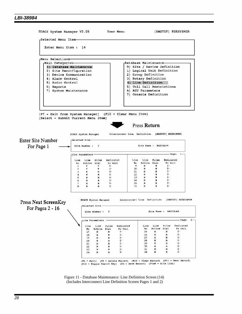
Figure 11 - Database Maintenance: Line Definition Screen (14) (Includes Interconnect Line Definition Screen Pages 1 and 2)
LBI-38984
28

5) TOLL CALL RESTRICTIONS
The Toll Call Restrictions function under the Database Maintenance main category screen, item "15", is used to identifyoutgoing telephone call restrictions assigned to different levels of radio users. Up to 16 restrictions levels can be set up withthis screen.
When Toll Call Restrictions is selected, (i.e., screen number 15), pressing Return displays the Interconnect Toll Call Re-strictions Selected Site window. This window contains fields for the Site Number and Site Name. The cursor appears first atthe Site Number. Typing in the Site Number displays the Toll Call Parameters screen 1:1 just below the Selected Site screen.
A typical view of the User Menu, the Selected Site screen with Toll Call Parameters screen 1:1 is shown in Figure 12.
Selected Site
Site Number: Numeric designation of the site.
Site Name: Up to an eight-character alphanumeric site name.
Screen 1:1 - Toll Call Parameters
The Toll Call Parameters screen consists of two similar sections. The first section contains line numbers 1 through 8, whilethe second section contains line numbers 9 through 16. Both sections contain a Digit pattern (for four digits), and RestrictionLevels (up to 16 levels) for each line number.
Digit Pattern: Enter the first four digits of the telephone number on which restriction levels are in effect. All unuseddigit pattern spaces are filled with four periods (....).
Restriction Level: The 16-position restriction level field indicates the toll line restrictions that apply to each radio. The codeheading of 0 to 15 corresponds to the code assigned to each radio unit allowed to make toll calls. Thiscode is assigned in the field under Logical Unit Definition (Item 11).
Enter Y in this field under units permitted to make telephone calls with the first four digits indicated un-der Digits Pattern. Enter N (default) if the radio unit is not to make toll calls to the phone numbers withthe digits indicated.
An "X" can be used in the Digit Pattern field to represent any digit from 0 through 9.
NOTE
LBI-38984
29

Figure 12 - Database Maintenance: Toll Call Restrictions (Screen 15)(Includes Interconnect Toll Call Restrictions Screen 1:1)
LBI-38984
30

6) ACU PARAMETERS
ACU (Alarm Control Unit) Parameters under Database Maintenance main category, screen "16", displays a list of 32alarms associated with each site, allowing you to define the parameters for each alarm. The default values are used by the SiteController when first powered up, and remain in effect until the desired parameter changes are made to the database for eachindividual system.
When ACU Parameters is selected (item 16), pressing Return displays the Alarm Control Unit Definition Selected Sitewindow. This window contains fields for the Site Number and Site Name. Typing in the Site Number displays the ACU Pa-rameters window (1:2) just below the Site Selection window. The second ACU Parameters window (2:2) is displayed bypressing Next Screen. The screen numbers appear at the top right of each screen.
The ACU Parameters window consists of two similar sections, the first for ACU’s 1-8 (or 17-24), and the second forACU’s 9-16 (or 25-32). Each section contains five data columns. The ACU number is in the first column. The second columncontains the Alarm Name field. The third, fourth and fifth columns show the Enabled, Active High and Major fields.
A typical view of the User Menu, the Selected Site and ACU Parameters screens 1:2 and 2:2 is shown in Figure 13.
Selected Site
Site Number: Numeric designation of the site.
Site Name: Up to an eight-character alphanumeric site name.
Screens 1:2 and 2:2
ACU No: The number of the ACU currently highlighted.
Alarm Name: Alphanumeric field for entering the Alarm name.
Enabled: Designates alarm lines enabled to report alarms. Enter Y in this column to enable alarm reporting. EnterN (default) to disable alarm reporting, or for alarms not used.
Active High: Designates enabled alarm lines defined as active high alarms, i.e., a low to a high transition indicatesalarm condition. Enter Y next to all enabled alarms designated active high alarms. Enter N next to all en-abled alarms active low (i.e., a high to a low transition indicates an alarm condition).
Major: Designates alarms defined as major alarms requiring immediate reporting and logging. Enter Y in thiscolumn next to all enabled alarms defined as major alarms. Enter N in this column next to all enabledalarms defined as minor alarms (alarm logged but not reported).
7) CONSOLE DEFINITION (Full Level Package)
The Console Definition allows you to enter a console ID, this function then automatically assigns LID’s and GID’s associ-ated with the console ID (SAID’s).
LBI-38984
31

Figure 13 - Database Maintenance: ACU Parameters (Screen 16)(Includes Alarm Control Unit Definition Screens 1:2 and 2:2)
LBI-38984
32

2) SITE RECONFIGURATIONThere are five functions that correspond to the Site Reconfiguration category, listed as 0) through 4). Each function screen
has two windows, a Selected Site and a parameters window. Unlike the other categories, each of the functions can be accessedby pressing the NEXT SCREEN or PREV SCREEN keys instead of returning to the User Menu first. The screens corre-spond in the following manner:
20) Channel ⇐⇒ 1:5- Channel Configuration
21) Call Parameters ⇐⇒ 2:5 - Channel Assignment Parameters
22) Test Parameters ⇐⇒ 3:5 - Site Test Parameters
23) Miscellaneous ⇐⇒ 4:5 - Miscellaneous Parameters
24) Relay ⇐⇒ 5:5 - Relay
For example, if you choose 21 from the Main User Menu, the Call Parameters screen is displayed consisting of the Se-lected Site window and the Channel Assignment window (2:5). If you want to get to the Miscellaneous Parameters screen(number 23), then you can press NEXT SCREEN twice and the Miscellaneous Parameters window (4:5) replaces the ChannelAssignment Parameters window.
A typical view of the User Menu and the Site Reconfiguration screens 1:5 through 5:5 are shown in Figures 14 and 15.
At the Site Number prompt in the Selected Site window, type in the site number for which changes are required. You canuse the FIND and SELECT keys to access a listing of sites and devices. The corresponding parameters window appears be-low the Selected Site window.
When changes have been made in the database, the letter N in the column between the Database window and the Site win-dow must be to a Y, indicating that a changes are ready to transmit. When the DO key is pressed, changes are sent to the siteand the site is reconfigured accordingly. Notice that the Site window is updated with the current site settings to match thechanges made in the Database window and Y is changed back to N.
0) CHANNEL
The Channel definitions under the Site Reconfiguration category temporarily redefine the default channel configurationsfor the selected site. Listed below are the field definitions for screen 1:5.
RF: Designates working channels and control channel. Enter C in one position to designate the control chan-nel. Enter Y to designate a working channel. Enter N (default) under all unused channels.
Changes made in the Site Reconfiguration category DO NOT affect the Database setting. After you exit to the MainUser Menu and return, you will notice that the parameters in the Database window have returned to their originalsetting. Also, if a power outage occurs, the site is restored to original Database settings when it is put back in service.Changes to the database must be made under the Database Maintenance category, Site/Device Definition (items 10-17).
NOTE
All of the Selected Site windows as well as the function key definitions at the bottom of the Site Reconfiguration screens1:5 through 5:5 are identical.
NOTE
LBI-38984
33

Interconnect: Designates channels equipped to handle telephone interconnect. Enter Y under channels that areequipped for telephone interconnect, or N (default) under unused channels and channels notequipped for interconnect.
Digital Voice: Designates channels equipped to handle digital voice transmissions. Enter Y under channelsequipped to handle digital voice or N (default) under unused channels and channels not soequipped.
Data: Designates channels are equipped to handle data transmissions from mobile data terminals. En-ter Y under channels equipped to handle data transmissions or N (default) under unused chan-nels and channels not equipped for data transfers.
Partition 2: Assigns a set of channels for special assignment to selected radios and groups. Enter Y for asecond partition, or N (default) for a normal partition.
Allowed CC: Designates a channel allowed to be a control channel. Enter Y for control channel capability, orN (default) if channel cannot be control channel.
Wide Area: Enter a Y on the channel configuration to allow the channel to be used in a multisite configura-tion. This allows a "Wide Area" of coverage. Enter N to disable Wide Area communication forthe channel or an unused channel.
Downlink: Designates a channel number to be used as a redundant downlink to the Multisite coordinator orconsole. Channel 26 is always assumed to be the primary downlink (default). Enter Y to enable.Enter N for unused and not downlink channels.
1) CALL PARAMETERS
The Call Parameter definitions under the Site Reconfiguration category temporarily redefine the default call parameters fora selected site. Listed below are the field definitions for screen 2:5.
Transmission Conv Limit: Sets the transmission conversation time limit for transmission trunked Calls. Time is expressedin seconds (x10) with a default setting of 30 (300 seconds or 5 minutes).
Message Conv Limit: Sets the conversation time limit for message trunked conversations. Time is expressed in sec-onds (x10) with a default setting of 30 (300 seconds or 5 minutes).
Interconnect Hang Time: The time between an unkey command and channel drop for telephone interconnect calls in sec-onds. Hang time is expressed in seconds with a default of 30.
Emergency Hang Time: The time between an unkey command and a channel drop for emergency calls. Hang time is ex-pressed in seconds with a default of 2.
Rotate Assignments: Enter Y (default) if you want Automatic Working Channel Assignment by the system. Enter Nto prevent Automatic Working Channel rotation.
Assign Chan Ascending: This field sets the order used by the Site Controller to make working channel assignments. En-ter Y (default) to assign channels in ascending order starting at one. Enter N to assign channelsin descending order starting from the highest channel number.
LBI-38984
34

Figure 14 - Site Reconfiguration (Screen 20)(Includes Site Reconfiguration Screens 1:5 and 2:5 -
Screens 3:5, 4;5 and 5:5 are shown in Figure 15 on the following page)
LBI-38984
35

Figure 15 - Site Reconfiguration(includes Site Reconfiguration screens 3:5, 4:5 and 5:5)
LBI-38984
36

Recent Call Queue Int: During times when calls are queued, the queue priority of a call may be increased by onehalf. The queue priority is incremented if the time between the last call request and currentrequest is less than the recent call queue interval. Interval range is from 0 to 30,000 milli-seconds (30 seconds), with a default of 5,000 milliseconds (5 seconds).
Max # Concurrent Intcon: Sets the maximum number of simultaneous telephone interconnect calls permitted on thesite. This field defaults to 2.
Max # Concurrent Indiv: Sets the maximum number of simultaneous individual calls permitted on the site. This two-digit numeric field defaults to 20.
2) TEST PARAMETERS
The Test Parameter definitions under the Site Reconfiguration category temporarily redefines the default test parametersfor the selected site. Listed below are the field definitions for screen 3:5.
Test Unit Enabled: Enter Y (default) to enable the Test Unit (TU). Enter N to disable the TU.
Local Test Unit: Indicates whether the TU is a local unit or a remote. Enter Y for local test unit, or N for re-mote.
Background Testcall Interval: Sets the length of time between background test calls in minutes. The range is from 0 to1440 (24 hours). The default value is 5. Entering a value of 0 inhibits background test calls.
Power Monitor Unit Enabled: Enter Y (default) to enable the Power Monitor Unit (PMU). Enter N to disable the PMU.
PMU Power Level: Sets the Power Monitor Unit (PMU) alarm threshold of the output power level for eachtransmitter channel. If the power level drops below the specified level, a PMU alarm is is-sued. Power level alarm threshold can be set from 0 to 255 x 10 (0 to 2,550 watts) with adefault of 3 (30 watts).
3) MISCELLANEOUS PARAMETERS
The Miscellaneous Parameter definitions under the Site Reconfiguration category temporarily redefine the default miscel-laneous parameters for the selected site. Listed below are the field definitions for screen 4:5.
Morse Code ID Intrvl: The time interval in minutes between transmissions of the Morse Code site identification(ID). The time interval range is from 1 to 30 minutes with a default of 15 minutes.
Scramble Data Call Int: The system is capable of placing random data calls on working channels to discourage un-authorized monitoring of the system. This field sets the length of time in seconds betweendata calls. The range is from 0 to 32,767 with a default of 5. A value of zero inhibits thisfeature.
Activity Dump Threshold: The number of activity records contained in the Site Controller activity file required beforethe start of a download (defaults to 1,000). A download dumps the activity file to the SystemManager. The threshold range is from 1 to 16,383 records. We recommend a value no lowerthan 500 for this field.
LBI-38984
37

Assign Nonadjacent Channels: Use alternating channel assignment algorithm to avoid intermodulation. Enter Y to enableor N (default) to disable.
4) RELAY
The Relay definitions under the Site Reconfiguration category temporarily redefine the default relay settings for a selectedsite. Listed below are the field definitions for screen 5:5.
Relay Number: Headings for relay numbers (1 - 8) that follow under Database Configuration and Site Con-figuration. These numbers correspond to the eight control output relays at the Test andAlarm Unit (TAU). The relays are latching and are used to control customersupplied equip-ment.
3) DEVICE COMMUNICATION
The Device Communication screen contains three categories. These categories are listed in the Device Communication win-dow as 0) through 2). Each of the three categories has one or more field definition screens.
0) DATABASE UPLOAD
After new records are added or existing records changed, the Database Upload function sends the selected databases fromthe System Manager to the designated Site Controller.
When one of the Database Upload categories is selected (i.e., item 30) pressing Return displays the Database Upload Re-quest screen.
The Database Upload function under the Device Communication category consists of only the Database Upload Requestscreen. This screen contains three sections; All Sites and Services, Sites Only, and Devices Only.
A typical view of the User Menu and the Database Upload Request screen in shown in Figure 16.
All Sites and Services
Full Logical ID Database: Enter Y for all Logical ID Database records to be uploaded to the sites and devices. Enter N(default) if you do not want this included in the upload.
Full Group ID Database: Enter Y in this field if you want all Group Database records sent to the sites and devices whenthe upload is performed. Enter N in this field if you do not want the records included in theupload.
Current Time: Enter Y if you want the records to reflect entries to the current time. Enter N (default) if you donot want these records included.
Logical ID Changes: Enter Y if you want to include only the changes in the Logical ID Database since the lastupload. Enter N (default) if you do not want LID changes included.
Group ID Changes: Enter Y if you want to include only the Group ID Database changes since the last upload. EnterN (default) if you do not want the Group changes included.
LBI-38984
38

Sites Only
Line Database: Enter Y in this field if you want Line Database records sent to the site when the upload is per-formed. Enter N (default) in this field if you do not want these records included in the upload.
Rotary Database: Enter Y in this field if you want Rotary Database records sent to the site when the upload isperformed. Enter N (default) in this field if you do not want the records included in the upload.
Toll Call Database: Enter Y in this field if you want Toll Call Restrictions records sent to the site when the uploadis performed. Enter N (default) in this field if you do not want the records included in theupload.
ACU Alarm Masks: Enter Y in this field if you want ACU Alarm Mask records sent to the site when the upload isperformed. Enter N (default) in this field if you do not want the records included in the upload.
Site Aliases: Enter Y in this field if you want the site name instead of the logical ID uploaded. Enter N (de-fault) if you do not want these records included.
LBI-38984
39

Figure 16 - Device Communication: Database Upload: (Screen 30)(Includes the Database Upload Request Screen)
LBI-38984
40

1) ACTIVITY DOWNLOAD
The Activity Download function displays the Activity Download Request window for downloading individual site activityrecords to the System Manager from individual sites.
This window contains fields for the Site Number and Site Name. You can use the Find and Select keys to obtain site infor-mation. Pressing Return toggles between the Site Number and Site Name fields. Pressing the Do key requests the download.
A typical view of the User Menu and the Activity Download Request window is shown in Figure 17.
Figure 17 - Device Communication: Activity Download (Screen 31)(Includes Activity Download Request Window)
LBI-38984
41

2) SITE MONITOR
The Monitor Activity function displays the status and activity of all channels at a site. This monitor display is continuouslyupdated by the Site Controller. Pressing the Return key after selecting the User Menu (function 32) displays the Selected Sitescreen. Typing in the site number connects you to the Channel Monitor screen.
You can abort the connection attempt by pressing function key F8 if the channels are busy, and the delay in connecting tothe site is too long. F8 also disconnects an existing connection.
A typical view of the User Menu, Selected Site and the Site Monitor screen is shown in Figure 18.
Channel Monitor
Chan: The channel number column.Status: This column shows the last reported status of the channel. (Busy, Free or Fail)Time: The time the call occurred.Caller: The originating LID column.Callee: The designation LID or GID column.Channel Activity: A brief description of channel activity.
Group Call, Individual Call, GETC CommError, etc)
Figure 18 - Device Communication: Site Monitor (Screen 32)
LBI-38984
42

4) ALARM CONTROLThe Alarm Control screen contains two categories. These categories are listed in the Alarm Control window as 0 and 1.
Each of these categories has one or more field definition screens. The first field definition screen (Selected Site) is accessed bypressing the Return key.
0) ALARM CONTROL DISPLAY
The Alarm Control screen allows you to tell the system how to report alarms associated with each channel. For each se-lected site use the function keys, defined at the bottom of the Alarm Display and Acknowledge screen, to enable, disable or ac-knowledge alarms. Alarms are enabled for notification of the current user, or are disabled from notifying the user. Notificationoccurs when the alarm changes from the dot to the bold, blinking diamond.
The Alarm Display is also used to monitor the alarm states of the selected site. The various alarm conditions are describedgraphically using a combination of different characters and different display attributes. Table 1 shows the various alarm states.
The diamond indicates an alarm, bold indicates an enabled state, and blinking indicates an unacknowledged state.
Use the cursor (arrow) keys to move to the different fields. Press F13 to acknowledge all alarms. Press the INSERT key toenable an alarm for notification and the REMOVE key to disable an alarm for notification. Pressing the Do key activates thechanges and saves the record of active alarms.
A typical view of the User Menu, Alarm Display and Acknowledge and the Selected Site and Current Alarms screens areshown in Figure 19.
Table 1 - Alarm States
CHARACTER ATTRIBUTES MEANING
Space Normal No alarm, disabled for notification
Centered dot Normal No alarm, enabled for notification
Diamond Normal Alarm, acknowledged, disabled
Diamond Normal, blinking Alarm, unacknowledged, disabled
Diamond Bold Alarm, acknowledged, enabled
Diamond Bold, blinking Alarm, unacknowledged, enabled
The alarm display updates at 10-second intervals if nothing is typed. The cursor returns to the site number field afterupdating.
NOTE
LBI-38984
43

Figure 19 - Alarm Control: Alarm Control Display (Screen 40)(Includes Alarm Display and Acknowledge screen)
LBI-38984
44

1) RELAY TRIGGER DEFINITIONS
The Define Relay Triggers function (Alarm Activated Relays screen) allows you to specify combinations of alarm occur-rences that trigger the alarm relay. Each relay combination defined on this screen must have a relay connected to the properalarm class.
Enter the relay number (1-8) in the Relay Number field. This identifies the relay triggered by the specified alarm. The re-lay number corresponds to the control output relays at the Test and Alarm Unit (TAU).
Press the TAB key or right cursor (arrow) key and enter the desired site number.
The "Normal State off (Y/N)" field indicates the normal state of the relay. Enter Yes if the normal relay state is deener-gized. A No in this field causes the relay to energize in the normal state.
The "Reset if Alarm clears (Y/N)" field allows you to specify alarm reset inhibit. Entering a Yes allows the alarm to resetwhen the cause is removed. Entering No latches the alarm state even after removing the cause of the alarm.
In the Input and Output Sites field, indicate sites (1-32) that are to receive relay outputs. Relay outputs are sent to the sitewhen the alarm trigger occurs. This allows controlling relays at any site by alarms occurring at other sites.
Press NEXT SCREEN to enter the Relay Trigger Definition screen. This screen allows you to indicate combinationsneeded to trigger the relay for each of the alarm classes. Table 2 provides a list of active alarm classes (0-15) and Figure 20 is atypical view of the User Menu and Alarm Activated Relays screens.
Entries for the Alarm Triggers can be N (No), 1 (one), or 0 (zero).
N - This alarm does not cause the relay to set.
1 - Performs a logical AND on alarms in the same class. All alarms marked with a 1 must be set before the alarm is reported.
0 - Performs a logical OR on alarms in the same class. This alarm cause relay set, regardless of other alarm states. Itis permissible to have both 1 and 0 triggers in the same class. Any or all of the alarm classes can specify triggers.
After entering the Alarm Triggers for a class, connect the relay by entering either a Y or N in the Connect field. Entering aYes connects the relay with the indicated site. Enter a No if not connecting the relay to the site. Press the DO key to save thedisplayed record. Alarm classes are logically OR’ed together, i.e. if you have a class with a logical AND and another classwith a logical OR the output of those two classes are OR’ed together. If you have multiple input sites they are also OR’ed to-gether.
LBI-38984
45

Table 2 - Alarm Class Definition
ALARM CLASS DEFINITION TRIGGER MEANING
0 - Not Used
1 - Poller Alarm Alarms issued by the poller for eachchannel.
0 - Not used, always set to N.l1 - Alarm for channel 1.2 - Alarm for channel 2.
2 - TU Alarm Alarms issued by the Test Unit foreach channel.
3 - Alarm for channel 3. • •
7 - Carrier Alarm Alarms issued by the GETC for an unexpected carrier on a channel.
•26 - Alarm for channel 26.27-31 - Not used, always set to N.
11 - Phone Line Alarm On voted systems, the GETC signalsa failure on the phone line.
Note: The Site Controller is designedto handle 25 channels and onedownlink channel.
3 - ACU Alarm Alarm issued by user suppliedequipment connect to the ACU. Userequipment can be connected to any ofthe 32-position alarm inputs.
ACU alarms are for both major andminor alarm types. The 32 fieldsrepresent the 32 alarm leads on theACU.
5 - PMU Alarm Alarms issued by the Power MonitorUnit for each channel.
0 - not used, always set to N.
1 thru 20 - PMU alarms for channels1 thru 20 only.
21 and 22 - Antennas 1 and 2 alarms.
23 thru 31 - Not used, always set toN.
6 - RIC Alarm Alarms issued by the RepeaterInterconnect Controller for eachchannel.
0 - not used, always set to N.
1 thru 20 - RIC alarms for channels1 thru 20 only.
21 thru 31 - Not used, always set to N
LBI-38984
46

Figure 20 - Alarm Control: Relay Trigger Definitions (Screen 41)
LBI-38984
47

5) RADIO CONTROLThere are four categories shown in the Radio Control screen. These categories are listed in the Radio Control window as 0
through 3. Each of these categories has one or more field definition screens. The Selection window is displayed by pressingthe Return key.
0) UNIT ENABLE/DISABLE
The System Manager has the ability to disable radio units remotely. This feature is used if a radio unit is stolen, or if a ra-dio is disrupting communications on the system. The System Manager can also enable a previously disabled radio.
When the Unit Enable/Disable function is selected, (i.e., function 50), pressing Return displays the Selected Unit windowof the Unit State Enable/Disable Screen.
A typical example of the User Menu, Radio Control and Unit State Enable/Disable screens is shown in Figure 21.
Selected Unit
Unit Number: A number (1 to 16383) that is associated with each radio unit in the system (the Logical ID).
Physical ID: A unique number (0-999999999) that identifies the radio unit. This is a 9-digit field.
Unit Type: A description of the unit (mobile, portable, console, etc.). Press Select for types of units.
Unit Name: A unique eight-character alphanumeric name that identifies the radio.
Serial Number: A unique 16-character alphanumeric field listing the serial number of the radio unit.
Asset Number: A unique 16-character alphanumeric asset identification number.
Current State
Entering a Logical ID in the Unit Number field displays the Current State screen. A typical example of the User Menu, Ra-dio Control and Unit State Enable/Disable screens is shown in Figure 21.
Current State: Displays the current operating state (enabled/disabled) of the radio.
Desired State: To change the operating state, enter the desired state and press F7 to Enable the radio, or F12 to Disable.This state change is sent to all sites.
Remotely Disabling A Radio
Radio Units can be temporarily disabled through the System Manager to prevent their unauthorized use. For the disablecommand to be effective, the radio unit must be operational and within range of the site.
To disable a radio: Press F12 to submit the request to the Site Controller. The Site Controller will attempt to disable the ra-dio unit. If the disable is successful, a confirmation message will be displayed.
LBI-38984
48

Figure 21 - Radio Control: Unit Enable/Disable (Screen 50)
LBI-38984
49

Remotely Enabling A Radio
Radio Units that have been temporarily disabled can be enabled for operation using the System Manager. For the enablecommand to be effective, the radio unit must be operational and within range of the site.
To enable a radio:
Press F7 to submit the request to the Site Controller. The Site Controller will attempt to enable the radiounit. If the enable is successful, a confirmation message will be displayed.
Canceling A Remote Enable/Disable Command
You can cancel an enable or disable command through the System Manager. For the cancel command to be effective, theprevious command must not have affected the radio.
To cancel an enable/disable:
Press F8 to submit the Cancel request to the Site Controller. If the Cancel command is successful, a con-firmation message will be displayed.
1) DYNAMIC REGROUP (Full Level Package)
The Dynamic Regroup function under Radio Control on the main category screen, item "51", enables a System Manageroperator to program up to 8 new talk groups into a radio over the air.
When the Dynamic Regroup function is selected, (function 51), pressing Return displays the Dynamic Regroup screen(See Figure 22). The cursor first appears in the Selected Unit section of the screen. Entering a unit number causes the unitname to appear and moves the entry cursor to the Group Number field. The operator proceeds to regroup the unit by makingentries in the Forced and Captive fields and then pressing DO. Field names and descriptions are given below.
Unit Number: The Unit ID, or Logical ID, of the radio to Regroup. The Unit ID entered here is validated against theLogical Database, disallowing the entry of Unit IDs which are not in the system. The cursor cannot leavethis field (except to leave the screen) unless a valid Unit ID has been entered or it is left blank. When aUnit ID is accepted, the Unit Name associated with it is displayed in the Unit Name field.
Unit Name: The Unit Name of the radio to Regroup. Like the Unit ID, the Unit Name is validated against the LogicalDatabase. The cursor cannot leave this field (except to leave the screen) unless a valid Unit Name hasbeen entered or it is left blank. When a Unit Name is accepted, the Unit ID associated with it is displayedin the Unit ID field.
Group Number: The Group ID of the talk group to program into the radio. The Group ID entered here is validated againstthe Group Database, disallowing the entry of Group IDs not defined for the system. If a setting is not tobe Regrouped, the Group Number field should be left blank. The cursor cannot leave this field (except toleave the screen) unless a valid Group ID has been entered or it is left blank. For a valid Group ID, theGroup Name associated with it is displayed in a message in the general message area at the bottom of thescreen when the cursor is positioned in the field. Group IDs entered here do not have to have been pro-grammed into the radio via the PC Programmer.
Forced: When Group IDs entered on this screen are fully programmed into the radio, the radio can be "forced"(changed) to one of the new groups. A "Y" in this field sets the Group ID the radio is "forced" to enterwhen Regrouped. If none of the Regroup Group IDs are tagged "forced" in this fashion, the radio’s cur-rent group setting is left as it is and a hardware switch is activated by the radio operator to reqroup.Since it does not make sense for more than one Group ID to be forced, the screen enforces this rule byallowing only one Y in the forced column. If a Group ID is already forced (set "Y") and attempt is madeto force a second group, the original forced setting is deleted (set to "N").
LBI-38984
50

Figure 22 - Dynamic Regroup (Screen 51)
LBI-38984
51

Captive: This field is used in conjunction with the forced field. If it is desired that the radio being Regrouped notbe allowed to switch away from a forced group, set this field to "Y". If this field is "N", the correspond-ing forced Group ID (if any) may be deselected by the radio operator. Since a Group ID can only be cap-tive if it is forced, the screen enforces this rule. If a nonforced Group ID is selected as Captive, theforced field is set to "Y" and any other forced field is reset to "N".
Current RadioStatus:
This field is not a data entry field, but is used to display radio Regroup status information. Valid radiostates are: Not Regrouped, Regrouped, Regroup Pending, and Cancel Pending. When a radio is Re-grouped or an existing Regroup is canceled, the radio acknowledges the completed action. A "Pending"status indicates that radio acknowledgment has not been received. A "Regrouped" or "Not Regrouped"status indicates that this action has been acknowledged by the radio and was successful.
Function Keys:
F6 Exits the screen and returns to the Main Menu of the System Manager.
F8 A fully Regrouped radio can be returned to its normal (not Regrouped) state by pressing this key. If anystatuses are still pending, this key has no effect. A radio must be fully Regrouped or not Regrouped be-fore it can be canceled. Canceling an unRegrouped radio doesn’t really make sense, but it has no effectso it is allowed.
Do A fully unRegrouped radio may be Regrouped with the Group IDs on the screen by pressing this key. Ifany statuses are still pending, this key has no effect. A radio must be fully Regrouped or not Regroupedbefore it can be canceled. A radio with Regroup settings already in it may be Regrouped again; the oldRegroup settings are merely overwritten with the new ones.
F10 This key clears a data entry field to all blanks. It is provided as a convenience to the operator, saving theoperator from excessive delete use.
LBI-38984
52

2) MULTISITE UNIT LOCATION (Full Level Package)
The Multisite Unit Location screen under Radio Control on the main category screen, item "52", displays the site andgroup location of any radio unit in a multisite coordinator. This screen is only used with multisite networks.
When the Multisite Unit Location function is selected, (function 52), pressing Return displays the Unit Location Displayscreen (See Figure 23). The cursor first appears in the Selected MSC section of the screen. The operator enters in secession,MSC number and Unit Number being located. The System Manager fills the remaining informational fields in the MSC andSelected Unit sections of the screen and finds and displays the unit’s latest Site and Group. Field names and descriptions aregiven below.
The unit location function allows a system manager operator to find out what the current location (current site and currentgroup) a radio unit s logged into from a Multisite coordinator.
Field Descriptions (Selected MSC)
MSC Number: The MSC number entered is for the multisite coordiniator that contains the units to be tracked. The MSCnumber is validated against the external device database. The user can type in the MSC number or usethe Find key to select the MSC of interest. After you type in the MSC number, hit carriage return to enterthe MSC number and move the cursor to the unit number field. The range of the MSC number is be-tween 32 to 64.
MSC Name: The MSC name field is automatically entered from the external device database. The user cannot makeinputs in this field. This field is for display purposes only.
Field Descriptions (Selected Unit)
Any field in the Selected Unit section of the display can be used to activate the Unit Location function. The F14 keymoves the cursor between fields.
Unit Number: The Unit number, or Logical id, entered is for the radio to be tracked (or located). The range of valid unitnumbers is between 0 and 16383 (inclusive). To invoke the unit location function, the user types in theunit number and hits carriage return.
Physical Id: A unique number (0999999999) that identifies the radio unit. This is a 9 digit field. This field can be en-tered if the cursor is presently in the Selected Unit section of the display by using the F14 key to positionthe entry cursor. To invoke the unit location function, the user types in the physical ID number andpresses carriage return.
Unit Type: A description of the unit (mobile, portable, desktop). The user can press Find and Select for a list of validunit types. The user can activate the function by an entry in this field if the cursor is in the Selected Unitsection of the unit location screen by using the F14 key to position the entry cursor. To invoke the UnitLocation function, the user types in the unit type or presses the Find and Select keys and then pressescarriage return.
Field Descriptions (Selected Unit)
Unit Name: A unique eight-character alphanumeric name identifying the radio. The user can enter this field if thecursor is in the Selected Unit section of the unit location screen by using the F14 key. To invoke the unitlocation function, the user types the unit name in the field and presses carriage return.
LBI-38984
53

Figure 23 - Multisite Unit Location (Screen 52)
LBI-38984
54

Serial Number: A unique 16-character alphanumeric serial identification number. The user can enter this field if the cur-sor is in the Selected Unit section of the unit location screen by using the F14 key. To invoke the unit lo-cation function, the user types in the serial number in the field and presses carriage return.
Asset Number: A unique 16-character alphanumeric asset identification number. The user can enter this field if the cur-sor is in the Selected Unit section of the unit location screen by using the F14 key. To invoke the unit lo-cation function, the user types in the asset number in the field and presses carriage return.
Field Descriptions (Current Location)
Located on site: Field showing the radio unit’s current logged site. This field is updated every 5 seconds to track the cur-rent logged site location for the radio unit.
Active in group: Field used to indicate the latest group that the radio unit used to talk. This field is updated every 5 sec-onds to track the groups used when the radio unit talks.
Function Keys:
F6 Exits the screen and returns to the main menu of the System Manager.
F8 Cancel a current unit location request session. After a user has made a unit location request, the screen isupdated every 5 seconds with the current unit location.
F10 Used to clear the current unit record on the screen.
F11 Used to get the next radio ID and do a unit location on that radio.
F14 Used to toggle the search key for the logical database if the cursor is in the Selected Unit section of theunit location screen.
Find Used to find an MSC site ID if the user is in the Selected MSC portion of the screen. If the user is in theSelected Unit portion of the screen, it is used to select the current unit.
3) MULTISITE GROUP LOCATION (Full Level Package)
The Multisite Group Location screen under Radio Control on the main category screen, item "53", displays the numberand name of sites and the count of units in those sites in a multisite coordinator. This screen is only used with multisite net-works.
When the Multisite Group Location function is selected, (function 53), pressing Return displays the Group Location Dis-play screen (See Figure 24). The cursor first appears in the Selected MSC section of the screen. The operator enters in seces-sion, MSC number and Group ID. The System Manager fills the remaining informational fields in the MSC and SelectedGroup sections of the screen and finds and displays the Site Names and Unit counts for the selected Group. Field names anddescriptions are given below.
LBI-38984
55

Figure 24 - Multisite Group Location (Screen 53)
LBI-38984
56

Field Descriptions (Selected MSC)
Msc Number: The MSC number is entered for the multisite coordiniator that the system manager is interrogating. TheMSC number is validated against the external device database. The user can type in the MSC number oruse the Find and Select keys to select the MSC that is desired for the Group Location function. After youtype in the number hit carriage return and the entry cursor moves down to the Group ID number field.The range of the MSC number is between 32 and 64.
MSC Name: The MSC name field is the name of the MSC from the external device database. The entry is made auto-matically following Group ID input. This field is for display purposes only and not operator entries.
Field Descriptions (Selected Group)
Any field in the Selected Group section of the display can be used to activate the Group Location function. The F14 keymoves the cursor between fields.
Group Number: The group identity that the user requires for display of Sites and Unit counts. To invoke the group loca-tion function, the user types in the group identity and presses carriage return. The range of the groupnumber is between 0 and 2047 (inclusive).
A/F/S: A set of three fields (one for agency number, one for fleet number and one for subfleet number). Theuser can activate the function by an entry in this field if the entry cursor is in the Selected Group sectionof the group location screen by using the F14 key to position the entry cursor. To invoke the group loca-tion function, the user types in the A/F/S numbers and hits carriage return.
Group Name: A unique eight-character alphanumeric name that identifies the group. The user can activate the functionby an entry in this field if the entry cursor is in the Selected Group section of the Group Location screenby using the F14 key to position the entry cursor. To invoke the group location function, the user types inthe Group Name and presses carriage return.
Group Type: A unique eight-character alphanumeric description of the group type, such as Agency, Fleet, Subfleet,Patch, Simulselect, Other. The user can activate the function by an entry in this field if the entry cursor isin the Selected Group section of the Group Location screen by using the F14 key to position the entrycursor. To invoke the Group Location function, the user types in the Group Type or uses the Find and Se-lect keys to enter a valid Type and hits carriage return.
Field Descriptions (Current Location)
Site/Name: The number and the name of the site that has an active group. The site number and name are highlightedwhen the group is active on that site.
Count: The number of radios in the group on the site. This column is to the right of the Site/Name.
Function Keys
F6 Exits the screen and returns to the main menu of the System Manager.
F8 Cancel a current Group Location request session. After a user has initiated a Group Location request, thescreen is updated every 5 seconds with the current group information.
F10 Used to clear the current group record on the screen.
LBI-38984
57

F11 Used to get the next group ID and do a Group Location on that group.
F14 Used to toggle the cursor between entry fields while the user is in the Selected Group portion of theGroup Location screen.
Find Used to find an MSC site ID if the user is in the Selected MSC portion of the screen. If the user is in theSelected Group portion of the screen, it is used to select the current group.
6) REPORTS
There are ten categories shown in the Reports screen. These categories are listed in the Reports window as 0) through 9).Each of these categories, if present, have one or more field definition screens. The definition screen for each category is ac-cessed by pressing the Return key.
When the parameters for a report generation have been entered, pressing the Do key causes the report to be generated.When the generation is complete, a message is displayed in the status line of the screen.
0) DEVICE REPORT
The Device Report consists of a Site/Device Report Menu screen that provides information about devices identified in theSystem Manager database. The screen contains two windows, a Device Select and a Report Contents Menu window. Press Re-turn from User Menu, item 60, to display the Site/Device Report Menu screen.
The Site/Device Report Menu screen consists of three windows; a window with three fields which allows you to select thetype of report as follows: BY NAME, ALL SITES, or OTHERS. The screen also includes a Device Select Menu window anda Report Contents window.
The Device Select Menu window will change for each type of report selected. Use the cursor (arrow) keys or the Tab keyto change fields or windows.
A typical example of the Reports/Device Report Menu with all of the different reports Contents windows is shown in Fig-ure 25.
Select Menu
The Select Menu default is ALL SITES.
1) LOGICAL UNIT
The Logical Unit report allows you to print reports containing information about selected radio units identified in the Sys-tem Manager database. Pressing Return from User Menu item 61, displays the Logical Report Menu.
The Logical Report Menu screen consists of two main windows; a Quick Select Menu window and a Quick Sort Menuwindow. You can use the cursor or Tab keys to select the information fields to enter the information determining the parame-ters of the report, and the manner in which this information is presented (Sorted). Definitions for the two windows are listedbelow.
A typical example of the Reports/Logical Unit Menu with all of the different reports Contents windows is shown in Figure26.
LBI-38984
58

Quick Select Menu
Range Definition: Allows you to define the range of Units, Unit IDs, Home Groups, etc., listed below.
Unit Name: An eight-character, alphanumeric field for the unit range included in the report. The default for this fieldis spaces.
Unit ID: Specifies the Unit ID number (0-16383) for the unit range included in the report. The default for thisfield is 0 to 16383. This field is required when this is the Sort Key (Unit).
Home Group: Specifies the group ID (0-2047) for the group range included in the report. This field is required whenthis is the Sort Key (Group). The default for this field is 0 to 2047.
Unit Type: A list of the different type radio units that can be selected (tagged) for a report. You can tag Mbl (mobileunits), Port (potables) or any of the unit types that are listed by selecting the desired unit type with theSelect function key.
Department: Enter the alphanumeric Department select range in these two fields. Enter the starting Department nameassociated with the radio units in the first field. Enter the end Department name in the indented field.
Asset #: Enter the alphanumeric start Asset Number in the first field. Enter the end Asset Number in the indentedfield.
Comment: A 32-character comment field that allows you to define the select range end.
Quick Sort Menu
LBI-38984
59

Figure 25 - Reports: Device Reports (Screen 60)(Includes Site/Device Report Menu)
LBI-38984
60

The Quick Sort Menu window allows you to control the selection and priority of sort keys. This window consists of twocolumns: Sort and Priority.
The Sort column allows you to select sort keys, and the Priority column displays the sort key priority. For example, if yourfirst choice is to sort the report by Unit Name, (for example, if your first choice is to sort the report by Unit Name), enter a Yin the Unit Name column first. A "1" will appear in the Priority column for Unit Name. If your second choice is by AgencyName, enter a Y in the Agency Name column. A "2" will appear in the Priority column for Agency Name.
Figure 26 - Reports: Logical Unit (Screen 61)
LBI-38984
61

Unit Name: Entering Y in this field sorts the report alphanumerically by unit name.
Unit Id: A Y in this field sorts the report by Unit Id number.
Agency Name: A Y in this field sorts the report by agency name.
Serial #: A Y in this field sorts by Serial number.
Home Group: Entering a Y in this field sorts the report by the name of the home groups.
Unit Type: A Y in this field sorts the report by unit type.
Asset #: A Y in this field sorts the report by the unique asset number of the radio units.
Department: A Y in this field sorts the report by the Department name associated with the radio unit.
Default Sort Unit Id: If no sort method is selected (i.e., no "Y"s in Sort column), the report is sorted by unit Id number.
2) GROUP
The Group report allows you to print reports containing information about selected groups in the System Manager data-base. Pressing Return from Main Menu item 62, displays the Group Report Menu.
The Group Report Menu screen consists of two main windows; a Quick Select Menu window and a Quick Sort Menu win-dow. You can use the cursor or Tab keys to select the information fields to enter the information determining the parameters ofthe report, and the manner in which this information is presented (Sorted).
Definitions for the two windows are listed below. A typical example of the Reports/Group Report Menu with all of the dif-ferent reports Contents windows is shown in Figure 27.
Quick Select Menu
Group Id: Enter the alphanumeric range of Group Id numbers to be included in the report. Default range is 0 to2047.
Group Name: Enter the range of group names (alphanumeric field) for the group range included to be included in thereport.
Group Type: Enter the type of groups to be included in the report: All (all groups), Agn (Agencies), Fleet, or Subfl(Subfleets). The default for this field is All (all groups). Use the Select function key to select the typegroups to be printed in the report.
Division: Enter the range of alphanumeric Division names to be included in the report.
Quick Sort Menu
The Quick Sort Menu window allows you to control the selection and priority of sort keys. This window consists of twocolumns: Sort and Priority.
The Sort column allows you to select the sort keys, and the Priority column displays the sort key priority. For example, ifyour first choice is to sort the report by Group Name, enter a Y in the Group Name column. A "1" appears in the Priority col-umn for Group Name. If your second choice is to sort by Agency Name, enter a Y in the Agency Name column. A "2" appearsin the Priority column for Agency Name.
LBI-38984
62

The default for the Sort column in N, and the default for the Priority column is 0.
Group Id: Enter Y in this column to sort by Group Identification number.
Group Name: Enter Y in this column to sort by alphanumeric group name.
Agency Name: Enter Y in this column to sort by alphanumeric Agency name.
Group Type: Enter Y in this column to sort by Group Type.
Division: Enter Y in this column to sort by Division names.
Figure 27 - Reports: Group (Screen 62)(Includes Group Report Menu)
LBI-38984
63

3) ACTIVITY DETAIL
The Activity Detail Report function generates a report that includes a detailed description of all calls made at a site duringa certain time period. Pressing RETURN from the Main Menu item 63, displays the Activity Details Report screen.
The ending time displayed on the screen is the time of the entry into the screen, and is not the end time of the data con-tained on the System Manager for the site selected. Therefore, when doing activity reports with a time range in the same dayas today, you should do an activity download on the site and then wait for the download to complete. Once the download com-pletes, you can submit the activity report.
The Activity Details Report screen consists of two main windows; a Select Criteria window and a Sort Criteria window.You can use the cursor or Tab keys to select the information fields to enter the information determining the parameters of thereport, and the manner in which this information is presented (Sorted). Definitions for the two windows are listed below.
A typical view of the User Menu and Activity Detail Report screen is shown in Figure 34.
Select Criteria
Call Types: Enter the call types to include in the report: All (all call types), Indv (Individual Calls) information, Spcl(Special Calls) information, Emer (Emergency Call) information, Grp (Group) information, Sys (System Call)information, or Data (Data Call) information. The default for this field is All (all calls). Highlight the call typeand press the SELECT function key to select the call types. More than one call type may be selected, selectAll to clear other selections.
Caller Lid: Enter the range of Caller logical IDs (0-16383) to be included in the report. The default setting is 1 to 16382.
Callee Lid: Enter the range of Callee logical IDs (0-16383) to be included in the report. The default setting is 0 to 16383.
Callee Gid: Enter the range of Callee Group IDs (0-2047) to be included in the report. The default setting is 0 to 2047.
Chanl Num: Enter the range of Channel numbers (0-31) to be included in the report. The default setting is 1 to 31.
Call Class: Enter the Call Classes to include in the report: All (all call classes), AV (Analog Voice Calls), DG (DigitalCalls), DVI (Digital Voice Interconnect Calls), IC (Interconnect Calls), or DAT (Data Calls). The default forthis field is All (all call classes). Highlight the call class and press the SELECT function key to select the callclass. More than one call class can be selected, select All to clear other selections.
Q Priority: Enter the Queue Priority range (0-15) to be included in the report. The default setting is 0 to 15.
Q Delay: Enter the Queue Delay range (0-6540) to be included in the report. The default setting is 0 to 6540.
Duration: Enter the activity duration range (0-6540) to be included in the report. The default setting is 0 to 6540.
Sort Criteria
The Sort Criteria window allows you to control the selection and priority of sort keys. This window consists of two col-umns: Sort and Priority.
LBI-38984
64

The Sort column allows you to select sort keys, and the Priority column displays the sort key priority. For example, if yourfirst choice is to sort the report by Call Type, enter a Y in the Call Type sort column. A "1" will appear in the Priority columnfor Call Type. If your second choice is by Caller Lid, enter a Y in the Caller Lid sort column. A "2" will appear in the Prioritycolumn for Caller Lid.
Call Types: Entering Y in this field sorts the report alphanumerically by call type.
Caller Lid: A Y in this field sorts the report by Caller LID number.
Caller Name: A Y in this field sorts the report by Caller Name number.
Callee Lid: A Y in this field sorts the report by Callee LID number.
Callee Name: A Y in this field sorts the report by Callee Name number.
Figure 28 - Reports: Activity Detail (Screen 63)
LBI-38984
65

Group Id: A Y in this field sorts the report by Group Id number.
Call Class: A Y in this field sorts the report by Call Class name.
Channel Num: A Y in this field sorts the report by Channel number.
Q Priority: A Y in this field sorts the report by the queue priority number.
Duration: A Y in this field sorts the report by activity duration.
4) ACTIVITY SUMMARY
The Activity Summary Report function reports the number and types of calls that occurred during a specified time periodat the site.
The ending time displayed on the screen is the time of the entry into the screen, and is not the end time of the data con-tained on the System Manager for the site selected. Therefore, when doing activity reports with a time range in the same dayas today, you should do an activity download on the site and then wait for the download to complete. Once the download com-pletes, you can submit the activity report.
The Activity Summary Report screen consists of two main windows; a Select Criteria window and a Sort Criteria window.You can use the cursor or Tab keys to select the information fields to enter the information determining the parameters of thereport, and the manner in which this information is presented (Sorted). Definitions for the two windows are listed below.
A typical view of the User Menu and Activity Summary Report screen is shown in Figure 29.
Select Criteria
Call Types: Enter the call types to include in the report: All (all call types), Indv (Individual Calls) information, Spcl (Spe-cial Calls) information, Emer (Emergency Call) information, Grp (Group) information, Sys (System Call) in-formation, or Data (Data Call) information. The default for this field is All (all calls). Highlight the call typeand press the SELECT function key to select the call types. More than one call type can be selected, selectAll to clear other selections.
Caller Lid: Enter the range of Caller logical IDs (0-16383) to be included in the report. The default setting is 1 to 16382.
Callee Lid: Enter the range of Callee logical IDs (0-16383) to be included in the report. The default setting is 0 to 16383.
Callee Gid: Enter the range of Callee Group IDs (0-2047) to be included in the report. The default setting is 0 to 2047.
Chanl Num: Enter the range of Channel numbers (0-31) to be included in the report. The default setting is 1 to 31.
Call Class: Enter the Call Classes to include in the report: All (all call classes), CV (Clear Voice Calls), VG (Voice GuardCalls), VGI (Voice Guard Interconnect Calls), IC (Interconnect Calls), or DAT (Data Calls). The default forthis field is All (all call classes). Highlight the call class and press the SELECT function key to select the callclass. More than one call class can be selected, select All to clear other selections.
Q Priority: Enter the Queue Priority range (0-15) to be included in the report. The default setting is 0 to 15.
LBI-38984
66

Q Delay: Enter the Queue Delay range (0-6540) to be included in the report. The default setting is 0 to 6540.
Duration: Enter the activity duration range (0-6540) to be included in the report. The default setting is 0 to 6540.
Sort Criteria
The Sort Criteria window allows you to control the selection and priority of sort keys. This window consists of two col-umns: Sort and Priority.
The Sort column allows you to select sort keys, and the Priority column displays the sort key priority. For example, if yourfirst choice is to sort the report by Caller Lid, enter a Y in the Caller Lid sort column. A "1" will appear in the Priority columnfor Caller Lid. If your second choice is by Callee Lid, enter a Y in the Callee Lid sort column. A "2" will appear in the Prioritycolumn for Callee Lid.
Caller Lid: A Y in this field sorts the report by Caller LID number.
Callee Lid: A Y in this field sorts the report by Callee LID number.
Figure 29 - Reports: Activity Summary (Screen 64)
LBI-38984
67

Group Id: A Y in this field sorts the report by Group Id number.
Call Class: A Y in this field sorts the report by Call Class name.
Channel Num: A Y in this field sorts the report by Channel number.
5) ALARM
The Alarm Report provides a listing of site alarm conditions for a specific period. Alarm Types and channel numbers canbe specified for the report. Customary defaults are provided for the Alarm Types.
The Alarm Report is shown in Figure 30. Appendix "D" defines Alarm types.
Figure 30 - Reports: Alarm (Screen 65)
LBI-38984
68

Enter the site number, move to the start window using the SELECT key or cursor. Enter the start date (dd-mmm-yyyy)and time (00:01 - 24:00). Move to the Stop window and enter the stop date and time.
Press the DO key to generate the report.
6) CHANNEL STATISTICS
The channel statistics report provides channel availability and channel activity information for each channel at a site. Thisinformation is useful in determining system loading.
A typical view of the User Menu and Channel Statistics Report screen is shown in Figure 31.
Enter the site number, move to the start window using the SELECT key or cursor. Enter the start date (dd-mmm-yyyy)and time (00:01 - 24:00). Move to the Stop window and enter the stop date and time.
Press the DO key to generate the report.
Figure 31 - Reports: Channel Statistics (Screen 66)
LBI-38984
69

7) SITE STATISTICS
The site performance statistics report breaks down calls placed during each hour of site operation. It also provides informa-tion on call duration and call queuing.
A typical view of the User Menu and Site Statistics Report screen is shown in Figure 32.
Enter the site number, move to the start window using the SELECT key or cursor. Enter the start date (dd-mmm-yyyy)and time (00:01 - 24:00). Move to the Stop window and enter the stop date and time.
Press the DO key to generate the report.
Figure 32 - Reports: Site Statistics (Screen 67)
LBI-38984
70

8) EVENT LOG DISPLAY
The Event Log Display allows you to examine the events for a particular date. This report details all System Manager ac-tivity such as menu selections, upload requests, etc. Use the Tab or cursor keys to access the Date of Log to Examine field, andenter the desired date.
The various function keys, described at the bottom of the screen, allow you to move through the log.
Figure 33 - Reports: Event Log Display (Screen 68)
LBI-38984
71

9) REPORTS MANAGER
The Report Manager allows you to print, view, or delete reports generated by report screens 1) through 7). It also allowsyou to verify that the report contents matches the database information in the System Manager.
Enter the Reports Manager (69) by pressing the SELECT key. This enters the Reports Manager screen. The screen dis-plays a scrolling list of previously generated reports. Use the Up and Down arrow keys to highlight the desired report.
The highlighted report is printed by pressing (F10 key), viewed on the terminal by pressing (F11 key), or deleted by press-ing (F12 key).
Figure 34 shows a typical view of the User Menu and Reports Manager Display screen.
Figure 34 - Reports: Reports Manager Display (Screen 69)
LBI-38984
72

7) SYSTEM MAINTENANCE
There are eight categories shown in the System Maintenance screen. These categories are listed in the System Maintenancewindow as 0) through 7). Each of these categories has one or more field definition or archive and retrieve (backup and restore)screens. When in System Maintenance: Agency Partition Table 70), pressing the Return key displays the Agency Partition Ta-ble screen.
0) AGENCY PARTITION TABLE
The Agency Partition Table allows you to group radio units together to allow radio users with common purposes to com-municate freely with each other (group communications). Each agency can be further divided into fleets, and fleets dividedinto subfleets.
Through the Agency Partition Definition function of the System Maintenance Menu, the number of agencies, fleets, andsubfleets on the system are defined.
A simplified diagram showing examples of the different levels is shown in the following diagram:
The Agency Partition Table screen consists of two windows; an Agency Count window, and a window with three columnsnamed Agency, Fleet and Subfleet. A typical view of the User Menu and the Agency Partition Table screens are shown in Fig-ure 35.
Agency Count: Enter the Agency Count Number ( 1 - 32). This is the number (maximum) of Agencies to be defined in yoursystem.
Fleet: Move the cursor to the Fleet field of the first Agency (Agency 0). Enter the number of fleets to be defined un-der this agency. Repeat this procedure for each Agency listed on the screen.
Subfleet: The number of possible subfleets is automatically calculated by the System Manager based on the number offleets and agencies.
FLEET 2Transportation
SUBFLEET 2Fire Dept.
THIRD LEVEL SUBFLEET 1Police Dept.
FIRST LEVEL AGENCY(County or City)
SECOND LEVEL FLEET 1Public Safety
When setting up any system, the agency partition table must be created first. No user, unit, or group records can becreated until this table is defined.
NOTE
LBI-38984
73

Figure 35 - System Maintenance: Agency Partition Table (Screen 70)
LBI-38984
74

1) USER ACCOUNT MAINTENANCE
The User Account Maintenance under the System Maintenance function allows you to access all Agency, Fleet and Sub-fleet databases to set user parameters. The default values are used when the system is first powered up, and remain in effectuntil changed.
When User Account Maintenance has been selected, i.e., function number 71, pressing Return displays the Selected Userwindow.
This window contains a field for the User Name. Press Return after you enter the User Name to display the User Parame-ters window.
The User Account Maintenance consists of eight User Definition screens. Each User Definition consists of two basic win-dows, a Selected User window and a User Parameters or Menu Option window. These screens are numbered 1:8 through 8:8,and these numbers appear at the top right of each window following the Selected User window.
A typical view of the User Menu and User Definition screens 1:8 through 8:8 are shown in Figure 36.
Screen 1:8 - User Definition
Password: A 12-character field used to assign a password to the user account.
A/F/S Access: A set of three fields (one for agency number, one for fleet number and one for subfleet). When an agencynumber is specified, you have access to all records pertaining to radio units associated with fleets andsubfleets. When an agency and fleet number are specified, you have access to all records pertaining toradio units associated with the designated fleet and associated subfleets.
Captive Account: Defines account user access to the operating system. Entering an N in this field will allow the accountuser to exit the system manager and use the operating system. Entering a Y in this field (default) will notallow the account user access to the operating system.
User Note: Access to VMS (operating system) is not normally available to account users. For information on user access,please call Ericsson GE application engineering.
Default Site: The site entered in this field that will be affected by these menu option selections.
Device Access: Limits access to the database except for assigned devices. This prevents unauthorized access to sites. En-ter Y under the number of the device that you wish to allow access to the database. The default for thisfield is N.
Press Next Screen to access screen 2:8 from the User Parameters window 1:8.
All of the Group Identification screens as well as the function key definitions at the bottom of these screens are identicalfor screens 1:3 through 3:3.
NOTE
LBI-38984
75

Figure 36 - System Maintenance: User Account Maintenance (Screen 71)(Includes User Definition Screens 1:8, 2:8 and 3:8.
Screens 4:8 through 8:8 are shown on the following page.)
LBI-38984
76

Figure 37 - System Maintenance: User Account Maintenance (Screen 71)(Includes User Definition Screens 4:8 through 8:8)
LBI-38984
77

Screen 2:8 - Menu Options (Database Maintenance)
This screen consists of the Selected User window and the Menu Options window. The Menu Options window also has asecondary window that lists the functions for Database Maintenance screens.
Screen Access: Entering a N in this field denies the new user access to the Database Maintenance functions. Entering aY (default) allows the user access to this screen.
Press Next Screen to access the Menu Options (Site Reconfiguration) screen from the Menu Options (Database Mainte-nance) screen.
Screen 3:8 - Menu Options (Site Reconfiguration)
This screen consists of the Selected User window and the Menu Options window. The Menu Options window also has asecondary window that displays the functions for Site Reconfiguration screens.
Screen Access: Entering a N in this field denies the new user access to the Site Reconfiguration functions. Entering a Y(default) allows the user access to this screen.
Press Next Screen to access the Menu Options (Device Communication) screen from the Menu Options (Site Reconfigu-ration) screen.
Screen 4:8 - Menu Options (Device Communication)
This screen consists of the Selected User window and the Menu Options window. The Menu Options window also has asecondary window that lists the functions for Device Communication screens.
Screen Access: Entering a N in this field denies the new user access to Device Communication functions. Entering a Y(default) allows user access to this screen.
Press Next Screen to access the Menu Options (Alarm Control) screen from the Menu Options (Device Communications)screen.
Screen 5:8 - Menu Options (Alarm Control)
This screen consists of the Selected User window and the Menu Options window. The Menu Options window also has asecondary window that lists the functions for Alarm Control screens.
Screen Access: Entering a N in this field denies the new user access to Alarm Control functions. Entering a Y (default)allows user access to this screen.
Press Next Screen to access the Menu Options (Radio Control) screen from the Menu Options (Alarm Control) screen.
Screen 6:8 - Menu Options (Radio Control)
This screen consists of the Selected User window and the Menu Options window. The Menu Options window also has asecondary window that lists the functions for Radio Control screens.
Screen Access: Entering a N in this field denies the new user access to Radio Control functions. Entering a Y (default)allows user access to this screen.
Press Next Screen to access the Menu Options (Reports) screen from the Menu Options (Radio Control) screen.
LBI-38984
78

Screen 7:8 - Menu Options (Reports)
This screen consists of the Selected User window and the Menu Options window. The Menu Options window also has asecondary window that lists the functions for Reports screens.
Screen Access: Entering a N in this field denies user access to Reports functions. Entering a Y (default) permits user ac-cess to this screen.
Press Next Screen to access the Menu Options (Systems Maintenance) screen from the Menu Options (Reports) screen.
Screen 8:8 - Menu Options (Systems Maintenance)
This screen consists of the Selected User window and the Menu Options window. The Menu Options window also has asecondary window that lists the functions for Systems Maintenance screens.
Screen Access: Entering a N in this field denies the new user access to Systems Maintenance functions. Entering a Y(default) allows user access to this screen.
2) DATABASE ARCHIVE
The Database Archival procedure allows you to save (backup) the System Manager databases to tape. The Database Ar-chive Display can be accessed from the System Manager: Database Archive screen 72 by pressing the Return key. Use theTab key to enter the date fields to type in the dates.
The last archive date and today’s date are displayed.
Press the Do key to start the archive procedure.
A typical view of the User Menu and the Database Archive Display is shown in Figure 38.
LBI-38984
79

Figure 38 - System Maintenance: Database Archive (Screen 72)
LBI-38984
80

3) DATABASE RETRIEVAL
The Database Retrieval procedure allows you to retrieve (restore) archived System Manager databases. The Database Ar-chive Display can be accessed from the System Manager: Database Retrieval screen 73 by pressing the Return key. Use theTab key to enter the date fields, and then press Return to display the required tapes.
Next, enter the ending date for records to be saved in the Last Archive Date field. The default value is the most recent filein the System Manager. Press the Do key to start the archive procedure.
A typical view of the User Menu and the Database Retrieval Display is shown in Figure 39.
Figure 39 - System Maintenance: Database Retrieval (Screen 73)
LBI-38984
81

4) ACTIVITY ARCHIVE
The Activity Archive procedure allows you to save the preprocessed activity file from the Site Controller to tape. Archiv-ing the file is necessary to prevent the System Manager from automatically deleting the activity records whenever the presetstorage capacity is exceeded.
The Activity Archive Display can be accessed from the System Manager: Activity Archive screen 7) 4) by pressing the Re-turn key. Use the Tab key to enter the date fields, and then press Return to display the required tapes.
The ending date field defaults to today’s date and should not be changed. This means that activity for today will be backedup. Press the Do key to start the archive procedure.
A typical view of the User Menu and the Activity Archive Display is shown in Figure 40.
Figure 40 - System Maintenance: Activity Archive (Screen 74)
LBI-38984
82

5) ACTIVITY RE TRIEVAL
The Activity Retrieval procedure allows you to restore the archived activity files from tape to the Site Controller. The Ac-tivity Retrieval Display can be accessed from the System Manager: Activity Archive screen 75 by pressing the Return key.Use the Tab key to enter the date fields, and then press Return to display the required tapes.
Enter the starting date for activity records to be restored in the Beginning Date field. The default value is the earliest (old-est) archived activity file in the System Manager.
Next, enter the ending date for records to be restored in the Ending Date field. The default value is the most recent ar-chived activity file in the System Manager. Press the Do key to start the archive procedure.
A typical view of the User Menu and the Activity Retrieval Display is shown in Figure 41.
Figure 41 - System Maintenance: Activity Retrieval (Screen 75)
LBI-38984
83

6) SYSTEM BACKUP
The System Backup procedure allows you to make a copy of (backup) the entire system disk. The system backup providesa secure copy of all system parameters and software that can be quickly re-installed to restart the System Manager in the eventof a catastrophic equipment outage as a result of fires, floods, etc.
The System Disk Backup Display screen can be accessed from the System Maintenance: System Backup screen 76 bypressing the Return key. Instructions for performing the system backup are displayed on the System Disk Backup Displayscreen
A typical view of the User Menu and the Database Retrieval Display is shown in Figure 42.
Figure 42 - System Maintenance: System Backup (Screen 76)
LBI-38984
84

7) DISK SPACE MANAGER
Activity data is downloaded periodically from the sites and stored in a directory of the System Manager computer. Un-checked, this data will grow over time until the disk is filled. The Disk Manager solves this problem by maintaining activitydisk space at a user-settable level. Additionally, the Disk Space Manager is able to detect when an archive of activity data isnecessary and advises the operator to do so.
Of the total disk space used in activity files, a certain portion consists of files which have not been archived. Under normalconditions, total space is maintained at a fixed level by the Disk Manager, but the unarchived portion of the total disk spacegrows with time. The warning threshold can be set to 999999999, which stops all warning messages. Activity data is thenmaintained at the deletion threshold with no warning and no need to perform archives.
Deletion Threshold: Total disk space usage in activity files is maintained at the deletion threshold level. The Disk SpaceManager periodically checks total space against the deletion threshold and deletes the oldest activ-ity files as necessary to maintain this level. If warnings to perform an activity archive are ignored(i.e. an archive is not performed), eventually the amount of unarchived space equals the total space.When this occurs, messages are output to the terminal informing the operator that unarchived filesare being deleted ("Unarchived files being deleted **DATA L OSS**").
Warning Threshold: When the amount of unarchived disk space exceeds the warning threshold, messages are displayedon the screen advising that an activity archive should be performed. The Disk Space Manager peri-odically checks unarchived space against the warning threshold and output appropriate messagesadvising of this condition ("Perform backup: n bytes to data loss"). When an activity archive is per-formed, the operator is informed that conditions have returned to normal ("Disk usage returned tosafe limits").
Disk Checking Interval: The amount of time in seconds between disk space checks. The default valued of 600 seconds (10minutes) provides a good balance between CPU usage and responsiveness to changing disk usagefor most customers.
Recommended Settings:
1. Recommend using 90% of available space in Act and Log files. i.e. set deletion threshold to this value.
2. Recommend warning threshold set to 50% of deletion threshold. This gives a safe time margin between initial warning andloss of data.
3. If no warnings are desired (i.e. no backups will be performed) leave the warning threshold set at 999999999. This disableswarnings.
Table 3 - Disk Space Manager Recommended Settings
System Disk
ActDisk
Est. Avail for Act and Log
DeletionThreshold
WarningThreshold
A1 245 MB --- 111 MB 100 MB 50 MB
A2 426 MB --- 292 MB 263 MB 132 MB
A3 426 MB --- 263 MB 263 MB 132 MB
A4 426 MB --- 263 MB 263 MB 132 MB
A5 426 MB 426 MB 426 MB 383 MB 192 MB
LBI-38984
85

All Disk Space Manager activity is posted to the Event Log. Therefore, if files are deleted, information regarding the de-leted file is still available on the Event Log.
If repeated warnings of pending file deletion are not desired, set the Warning Threshold to a level larger than the DeletionThreshold. This will allow the system to automatically delete the oldest files automatically without warning.
A typical view of the User Menu and the Disk Space Manager is shown in Figure 43.
Figure 43 - System Maintenance: Disk Space Manager (Screen 77).
LBI-38984
86

APPENDIX A - MONITOR DISPLAY MESSAGES AND STATUS CHANGES
The following is a list of messages and status calls that may appear on the site monitor display.
4 BAD VOTED MSGS Four bad voted messages detected by the test unit.
CALL DENIED Caller has requested a service which cannot be performed.
CALL Q UEUED System fully loaded (all resources for this call are in use), call has been queued.
CARRIER PRESENT A carrier has been detected on the working channel. This usually indicates the presence of inter-ference or intermodulation (intermod).
CC POLL FAILURE The Control-Channel GETC failed to respond to its poll from the Site Controller.
CC POWER FAILURE This channel was the control channel, but the power monitor unit (PMU) has reported a powerfailure.
CC SYNTH LOCK The test unit could not lock its synthesizer on the control channel.
CDRP Call drop
CHNL DIAGNOSTICS This channel is out of service for a background test call.
CONSOLE ALARM The console has declared an RF/IF card failure for this channel.
CONTROL CHANNEL This channel is the control channel.
CONVERT TO CALLEE Caller placed a call to a group which was already on channel.
DOWNLINK CHANNEL This channel is a downlink trunking card (GETC).
DROP WITH CARRIER The working channel has dropped after its last call and a carrier has been detected (see CAR-RIER PRESENT).
EMERGENCY CALL A radio unit has declared an emergency call and an emergency group call is in progress.
GASN Group assignment.
GETC COMM ERROR A communications error has been detected by the Site Controller communication driver.
GROUP CALL A group call is in progress.
GROUP DATA CALL A group data call is in progress.
HIGH SPEED FAILED The test unit detected bad highspeed data on the working channel.
A-1
LBI-38984

IASN Individual assignment.
IN USE Channel is currently busy.
INDIV DATA CALL An individual data call is in progress.
INDI VIDUAL CALL An individual call is in progress.
INTERCONNECT CALL A radio-to-telephone interconnect call is in progress.
LOST CC SYNCH The test unit could not remain synchronized with the control unit.
LOW SPEED FAILED The test unit detected bad low-speed data on the working channel.
MORSE CODE ID A morse code identification message (repeater ID) is being broadcast over this channel.
NAVAIL Channel is not available.
NO CC FOUND The test unit could not find a control channel for its request.
NO CC HIGH SPEED Control channel high-speed data is bad or nonexistent.
NO CHNL ASSIGNED The test unit received no channel assignment when it requested a channel.
NO DROP SEEN The test unit did not see the channel broadcast a drop sequence.
NO SITE ID SEEN No site identification message has been seen.
OFF No trunking card (GETC) is defined to be at this position.
REPEAT MESSAGES The test unit has detected repeat messages on the control channel.
SASN Special assignment.
SYSTEM ALL-CALL A system all-call is in progress.
SYSTEM BUSY The system cannot handle the call request at this time.
TELEPHONE CALL A telephonetoradio call is in progress.
TEST CALL A test call originated by the Test Unit (TU) is in progress.
WC SYNTH LOCK The test unit could not lock its synthesizer on the working channel.
WRONG SITE ID The site number in the site identification message is incorrect.
A-2
LBI-38984
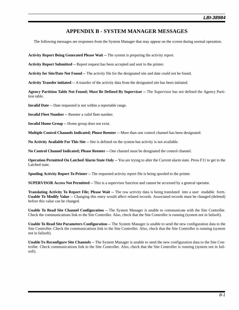
APPENDIX B - SYSTEM MANAGER MESSAGES
The following messages are responses from the System Manager that may appear on the screen during normal operation.
Activity Report Being Generated Please Wait -- The system is preparing the activity report.
Activity Report Submitted -- Report request has been accepted and sent to the printer.
Activity for Site/Date Not Found -- The activity file for the designated site and date could not be found.
Activity Transfer initiated -- A transfer of the activity data from the designated site has been initiated.
Agency Partition Table Not Found; Must Be Defined By Supervisor -- The Supervisor has not defined the Agency Parti-tion table.
Invalid Date -- Date requested is not within a reportable range.
Invalid Fleet Number -- Reenter a valid fleet number.
Invalid Home Group -- Home group does not exist.
Multiple Control Channels Indicated; Please Reenter -- More than one control channel has been designated.
No Activity Available For This Site -- Site is defined on the system but activity is not available.
No Control Channel Indicated; Please Reenter -- One channel must be designated the control channel.
Operation Permitted On Latched Alarm State Only -- You are trying to alter the Current alarm state. Press F11 to get to theLatched state.
Spooling Activity Report To Printer -- The requested activity report file is being spooled to the printer.
SUPERVISOR Access Not Permitted -- This is a supervisor function and cannot be accessed by a general operator.
Translating Activity To Report File; Please Wait -- The raw activity data is being translated into a user readable form.Unable To Modify Value -- Changing this entry would affect related records. Associated records must be changed (deleted)before this value can be changed.
Unable To Read Site Channel Configuration -- The System Manager is unable to communicate with the Site Controller.Check the communications link to the Site Controller. Also, check that the Site Controller is running (system not in failsoft).
Unable To Read Site Parameters Configuration -- The System Manager is unable to send the new configuration data to theSite Controller. Check the communications link to the Site Controller. Also, check that the Site Controller is running (systemnot in failsoft).
Unable To Reconfigure Site Channels -- The System Manager is unable to send the new configuration data to the Site Con-troller. Check communications link to the Site Controller. Also, check that the Site Controller is running (system not in fail-soft).
B-1
LBI-38984

Unable To Reconfigure Site Parameters -- The System Manager is unable to send the new configuration data to the SiteController. Check the communications link to the Site Controller. Also, check that the Site Controller is running (system not infailsoft).
Undefined Alarm Class Input; Please Reenter -- Alarm class must be R (Reset), E (Enable), or D (Disable).
Undefined Site -- Site requested is not defined on this system.
Value Out Of Range -- Entered value is out of the acceptable range.
You Are Already Sorting On This Field -- Sort option chosen has been selected in a prior Sort field.
You Must Fill Previous Sort Field First -- Previous Sort field has NO SORT as the selected option. Change the selected op-tion for the previous Sort field and try again.
B-2
LBI-38984

APPENDIX C
AUTOMATIC CONTROL CHANNEL ROTATION
This utility provides the customer with the ability to schedule automatic periodic rotations of the control channel on siteswith Site Controllers. The utility operates on a time basis, moving the control channel at an interval specified in the activatingcommand. It operates in a manner similar to the PDP System Manager’s control channel walker utility.
In order to utilize this feature, the SMSTART.COM file in SMCOM must be edited to include the command line(s) neededto start the program on the site(s) to which the feature is added.
The following procedure is used to add this feature to the system. Note that at any time during execution of the procedure,if you are concerned that something has been modified that is not part of the procedure, you can cancel all changes by pressingand holding <CTRL>and then pressing <Z>. At the resulting * prompt, type quit <cr>.
To get the feature activated, do the following:
Step•
ActionLog into the TEST2 account.
• Type in the command:
edit/edt smcom:smstart.com<cr>
• If the * prompt appears, type the following:
C<cr>
• Press <FIND> and type in the following:
untdis_det
then press <FIND> again.
• Using the arrow keys, position the cursor at the next line’s dollar sign and press <cr>.
• Press <UP ARROW> once to position the cursor at the beginning of the line just opened.
• Type in the following:
$set message/notext/nofacility/noidentification/noseverity<cr>
• Now, type the following line, requesting Automatic Control Channel Rotation. Replace ’site’ with the site number forwhich rotation is requested, ’rotation_rate’ with the rotation rate in the form hh:mm:ss.ss, and ’start_time’ with the ab-solute time the job is to start on the current day, in the form hh:mm:ss.ss.
$@smcom:control_channel_walker ’site’ ’rotation_rate’ ’start_time’<cr>
C-1
LBI-38984

As an example of this command line entry:
In this example site 9 is changed to automatic control channel rotation, with a rotation rate of 1 hour, starting at 23:59hours today. The entry would be:
$@smcom:control_channel_walker 09 01:00:00.00 23:59:00.00
• Repeat this entry for each site that is to have the control channel rotation. You should get a new line to fill for each siteentered.
• Finally, type in the following (NOTE: there is no <cr> at the end of this line to prevent the editor from creating anothernew line):
$set message/text/facility/identification/severity
• To save the changes, press the <CTRL> key and while holding it, press the <Z> key. This gets you back to the *prompt.
• At the * prompt, type:
exit<cr>
• Log out of the TEST2 account by typing:
logout<cr>
• Press <cr> once or twice until a VMS Username prompt appears, then type:
SHUTDOWN<cr>
and at the password prompt type (note you will not see anything on the screen when you type it):
SHUTDOWN<cr>
• Choose the option to reboot the system by typing:
R<cr>
Once the System Manager has rebooted, the additions in the SMSTART.COM file are activated. Verify the actions ofthe Control Channel Walker by using the Event Log display, screen 68, in the System Manager menu system. The ac-tion taken by the Control Channel Walker process should appear at or around the time you specified, and should reap-pear at or around the end of the time interval you specified in rotation_rate.
C-2
LBI-38984

APPENDIX D - ALARM REPORT DESCRIPTIONS
This Appendix gives information defining the various selectable Alarm Types. Prior to making these definitions an exam-ple is shown of typical alarm output. This is intended to orient the reader to the definitions that follow. It will be noted that thefirst page of output gives the alarm types enabled for logging and shows the Channels monitored.
Example Alarm report output:
Ericsson/GE EDACS 7-JUL-1993Alarm ReportSite Number : 5
Selected Alarm Types:
[*] External Device [*] Minor Alarm [*] Major Alarm [*] Test Calls [*] TU CC Fail [ ] Background Test Call[ ] Channel Diagnostics [*] Power Monitor Unit [*] Poller State Change [*] Carrier State Change[*] Auxiliary Alarm [ ] Channel Record [*] System Mgr Reconfig [*] Console RF/IF [*] RIC Status [*] Frame Sync Link [*] Phone Line [*] GETC Synth Fail [*] GETC Power Fail [ ] System Mgr Login [*] GETC Comm Error
Selected Channel Range: 1 to 31
D-1
LBI-38984

Ericsson/GE EDACS 7-JUL-1993Alarm Report Page : 1 Site Number : 5
Alarms Date : 17-JUN-1993
Time Alarm Description- - - - - - - - - - - - - - - - - - - -16:29:58.12 POLLER_STATE_CHANGE Changed Chan: 2, Channel Bits:
1C34567890123456789012345D78901 16:29:58.36 POLLER_STATE_CHANGE Changed Chan: 26, Channel Bits:
1C34567890123456789012345D78901 16:29:58.41 POLLER_STATE_CHANGE Changed Chan: 4, Channel Bits:
1C3W567890123456789012345D78901 16:29:58.43 POLLER_STATE_CHANGE Changed Chan: 1, Channel Bits:
WC3W567890123456789012345D78901 16:29:58.44 EXTERNAL_DEVICE_ACT Device Not Dead Normal Recovery Failsoft 16:33:38.18 GETC_COMM_ERROR Checksum err count: 0 Framing err count : 5
Overrun err count : 0 Parity err count : 0 Last err comm port: 2 17:08:34.30 SM_RECONFIGURATION Test Calls Are Off, Channel Bits:
WCWW567890123456789012345D7890----------------------------end of example report-----------------------------
Note that the alarm format includes not only the date of the printout but also the date of the occurrence of the alarms. Foreach alarm occurrence the time, identification, and description are given. Where applicable, following the words "ChannelBits:" an indicator (character) for each channel being monitored is shown. The meaning of each of these characters is definedbelow.
CHANNEL BITS CHARACTER DEFINITION
Character Meaning
C Indicates the control channel GETC.
D Indicates the primary downlink position.
W Working GETC; this is either a Downlink or an RF GETC. Indicates that for the alarm type given the channel is considered OK. (Console audio failure in "Console RF/IF".)
0 to 9 This is used as a placeholder. It indicates one of two things:
1) An alarm that is not used due to configuration of the system or limits on the alarm type’s reporting abilities, or
2) a failure indication.
D-2
LBI-38984

ALARM TYPE DEFINITION
External Device
This alarm type indicates a change in the state of equipment or externally provided alarm sources, like failsoft.
Minor Alarm
This is an ACU alarm output mask, showing alarms defined in the ACU database as minor alarms. You must reference theACU database to determine the actual meaning of these alarms as they are defined for each installation.
Major Alarm
This is an ACU alarm output mask, showing at least one alarm defined in the ACU database as a major alarm. All minoralarms, if any exist, are also displayed in the record. You must reference the ACU database to determine the actual meaning ofthese alarms as they are defined for each installation.
Test Calls
This record is used to indicate a Test Call on a RF channel that failed in the past, and is now trying to come back into serv-ice. This record is preceded by a Poller Alarm indicating the channel has passed the polling test of the Site Controller, or by aSystem Manager Reconfiguration request specifying that the channel tested is to be turned ON. This record does not appear inSimulcast systems using remote Test Units.
TU CC Fail
This record indicates the control channel listed has failed due to a problem detected by the Test Unit.
Background Test Call
This record indicates a normal system event for systems having Test Units connected to the Site Controller locally. Thisdoes not actually indicate an alarm unless the channel tested by this call is not displayed as working. This record is always pre-ceded by a Channel Diagnostics record.
Channel Diagnostics
This record precedes Background Test Call records for locally connected TUs, and Channel Records for remotely con-nected TUs. It tells when the indicated channel was taken out of service to perform the automated background checks.
Power Monitor Unit
This record indicates a change in state of a PMU power alarm on a RF channel or an antenna. Multiple alarms can be dis-played. The display of alarms indicates power alarms with a W at this time.
D-3
LBI-38984

Poller State Change
This record indicates a change in state of a GETC with respect to message polling between the Site Controller and theGETC. The GETC identity is indicated. Each record indicates a single channel state change. The state change can be deter-mined by examining the channels display for the record. If there is a W displayed, the channel is assumed to be OK from thepolling perspective.
Carrier State Change
This record indicates a carrier alarm state change on the channel specified. Carrier alarms occur when a RF GETC detectscarrier on the receiver when it should not be there. The resulting state can be determined by examining the channels displayfor the record. If there is a W displayed, the channel is assumed to be OK from the carrier alarm perspective.
Auxiliary Alarm
This record indicates an auxiliary alarm state change on the channel specified. Auxiliary alarms occur when a GETC issuesan alarm report, typically from a simulcasted system. The resulting state can be determined by examining the channels displayfor the record. If there is a W displayed, the channel is assumed to be OK from the auxiliary alarm perspective.
Channel Record
This record indicates a change in the state of the working RF GETCs in the system. It is an informational message loggedwhen the channels became active, and is used to report the status of the system channels after a remote Test Calls and SystemManager channel reconfigurations.
System Mgr Reconfig
This is used to report the message sent by System Managers to the Site Controller to change the RF channel configurationat the site.
Console RF/IF
This is used to indicate audio failures from console switches. A failure is indicated with a "W".
RIC Status
This indicates the current state of the system’s Repeater Interface Cards (RICs). The record is posted only when there is astate change on one of the RICs; however, to determine which RIC changed state, a previous RIC record or the system’s RICconfiguration must be known.
Frame Sync Link
This record will appear in the future.
Phone Line
This record indicates a state change on a phone line on the channel specified. Phone line alarms occur when a channelGETC does not detect data coming from a voter in a voted system. The resulting state can be determined by examining thechannels display for the record; if there is a W displayed, the channel is assumed to be OK from the phone line alarm perspec-tive.
D-4
LBI-38984

GETC Synth Fail
This record will appear in the future.
GETC Power Fail
This record will appear in the future.
System Mgr Login
This is an information record only, indicating a System Manager login attempt. If there was a failure, there could be a com-munications problem between the System Manager and the Site Controller or someone could be attempting to get into the SiteController’s communication line with an incorrect password.
GETC Comm Error
This record logs errors detected by the RS-232C serial multiplexers in the Site Controller. The errors are informational andcan indicate a problem with equipment configuration or cabling. Communications ports listed are not always GETC ports. All32 communication ports could appear in this message. Communication port mapping of Site Controllers is specified in the SiteController drawing and should be similar to the following:
Port Number Connected Device
0 System Manager Port1 to 26 GETC ports - primary downlink27 Test Unit (TU) if locally connected28 Alarm Control Unit (ACU)29 Power Monitor Unit (PMU)30 Line Interface Controller (LIC)31 Repeater Interface Controller (RIC)
D-5
LBI-38984

This page intentionally left blank
LBI-38984

APPENDIX E - GLO SSARY
ACU Alarm Control Unit
All Call A broadcast call made to all radio units.
Alphanumeric Fields Accepts all characters (symbols, numbers, and characters) available on the keyboard.
Analog Voice 1. A normal FM voice communication made over a EDACS system.2. A nondigital voice signal.
Cursor An indicator that shows your current position on the screen.
Date Fields Accepts dates in the format dd-mmm-yyyy, where:dd = numeric day of the monthmmm = first three letters of the monthyyyy = four digits of the year. Example: 01-AUG-1993
DEC Digital Equipment Corporation.
Download The process of receiving information from the Site Controller.
EDACS Enhanced Digital Access Communications System
Emergency Call A call placed over a EDACS system that utilizes special signalling and gives the caller the highestcommunications priority.
End Channel Number Defines the last channel number in a channel-number range that is to be included in a System Man-ager report.
End Duration The end time in seconds of an activity duration used with System Manager reports.
End Priority The ending priority number in a queue-priority range to be included in a System Manager report.
End Queue Delay The end time in seconds of a queue delay used with System Manager reports.
Field An area on a program screen where data is entered.
GID See Group ID, GID.
Group 1. A collection of radio users with a common communications requirement. 2. Radio users that areassigned a common group identification number on a EDACS system.
Group ID, GID A number used by the system to identify a communications group.
E-1
LBI-38984
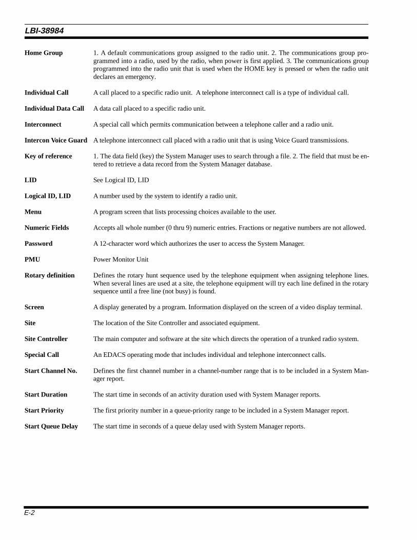
Home Group 1. A default communications group assigned to the radio unit. 2. The communications group pro-grammed into a radio, used by the radio, when power is first applied. 3. The communications groupprogrammed into the radio unit that is used when the HOME key is pressed or when the radio unitdeclares an emergency.
Individual Call A call placed to a specific radio unit. A telephone interconnect call is a type of individual call.
Individual Data Call A data call placed to a specific radio unit.
Interconnect A special call which permits communication between a telephone caller and a radio unit.
Intercon Voice Guard A telephone interconnect call placed with a radio unit that is using Voice Guard transmissions.
Key of reference 1. The data field (key) the System Manager uses to search through a file. 2. The field that must be en-tered to retrieve a data record from the System Manager database.
LID See Logical ID, LID
Logical ID, LID A number used by the system to identify a radio unit.
Menu A program screen that lists processing choices available to the user.
Numeric Fields Accepts all whole number (0 thru 9) numeric entries. Fractions or negative numbers are not allowed.
Password A 12-character word which authorizes the user to access the System Manager.
PMU Power Monitor Unit
Rotary definition Defines the rotary hunt sequence used by the telephone equipment when assigning telephone lines.When several lines are used at a site, the telephone equipment will try each line defined in the rotarysequence until a free line (not busy) is found.
Screen A display generated by a program. Information displayed on the screen of a video display terminal.
Site The location of the Site Controller and associated equipment.
Site Controller The main computer and software at the site which directs the operation of a trunked radio system.
Special Call An EDACS operating mode that includes individual and telephone interconnect calls.
Start Channel No. Defines the first channel number in a channel-number range that is to be included in a System Man-ager report.
Start Duration The start time in seconds of an activity duration used with System Manager reports.
Start Priority The first priority number in a queue-priority range to be included in a System Manager report.
Start Queue Delay The start time in seconds of a queue delay used with System Manager reports.
E-2
LBI-38984

System All Call A system-wide broadcast call made to all radio units belonging to the radio system.
System Manager A software package and computer system used to manage the database associated with the EDACSsystem. The System Manager maintains its own database and communicates with the Site Controller.
TU Test Unit, a radio-based test device at a radio site.
Upload The process of sending information from the System Manager to the Site Controller.
User Name An eight-character alphanumeric designation which identifies the operator to the System Manager.
E-3
Printed in U.S.A.
LBI-38984

ADDENDUM NO. 1 TO LBI-38984PCSM
This addendum provides user information for entering Channel Assignment data in two mislabeled data fields.
Page 15
Reference: Figure 7A - Database Maintenance: Site Device Definition (Screen 10), Sub-screen 2:4 (shown below).
Problem: When entering Channel Assignment Parameters in the Site Parameters screen (screen 2:4), time entered forthe Transmission Conversation Limit is stored in the Message Conversation Limit field and vice versa. This is due to theTransmission and Message Conversation Time Limit data field labels being reversed.
Corrective Action: Enter Transmission Conversation Time Limit in the field labeled “Message Conv Limit” and enterthe Message Conversation Time Limit into the field labeled “Transmission Conv Limit.”
Page 35
Reference: Figure 14 - Site Reconfiguration: Call Parameters (Screen 21), or Sub-screen 2:5 (shown below).
Problem: When entering Channel Assignment Parameters in the Site Reconfiguration screen (screen 2:5), time enteredfor the Transmission Conversation Limit is stored in the Message Conversation Limit field and vice versa. This is due to theTransmission and Message Conversation Time Limit data field labels being reversed.
Corrective Action: Enter Transmission Conversation Time Limit in the field labeled “Message Conv Limit” and enterthe Message Conversation Time Limit into the field labeled “Transmission Conv Limit.”
EDACS System Manager External Device Definition [SMGTGT] EGESYSMGR
ÚSelected Device ÄÄÄÄÄÄÄÄÄÄÄÄÄÄÄÄÄÄÄÄÄÄÄÄÄÄÄÄÄÄÄÄÄÄÄÄÄÄÄÄÄÄÄÄÄÄÄÄÄÄÄÄÄÄÄÄÄMODIFY¿³ Device Number : 5 Device Name : MSDS 3 ³³ Device Type : SITE ³ÀÄÄÄÄÄÄÄÄÄÄÄÄÄÄÄÄÄÄÄÄÄÄÄÄÄÄÄÄÄÄÄÄÄÄÄÄÄÄÄÄÄÄÄÄÄÄÄÄÄÄÄÄÄÄÄÄÄÄÄÄÄÄÄÄÄÄÄÄÄÄÄÄÄÄÄÄÄÄÙÚSite Parameters ÄÄÄÄÄÄÄÄÄÄÄÄÄÄÄÄÄÄÄÄÄÄÄÄÄÄÄÄÄÄÄÄÄÄÄÄÄÄÄÄÄÄÄÄÄÄÄÄÄÄÄÄÄÄÄÄÄÄÄÄ2:4¿³ ³³ Channel Assignment Parameters Miscellaneous Parameters ³³ Transmission Conv Limit : 270 Morse Code Id Interval : 5 ³³ Message Conv Limit : 290 Scramble Data Call Int : 0 ³³ Interconnect Hang Time : 20 Activity Dump Threshold : 500 ³³ Emergency Hang Time : 10 Assign Non-Adjacent Chan: N ³³ Rotate Assignments : Y ³³ Assign Chan Ascending : Y ³³ Recent Call Queue Int : 30000 ³³ Max # Concurrent Intcon : 3 ³³ Max # Concurrent Indiv : 2 ³³ ³³ ³ÀÄÄÄÄÄÄÄÄÄÄÄÄÄÄÄÄÄÄÄÄÄÄÄÄÄÄÄÄÄÄÄÄÄÄÄÄÄÄÄÄÄÄÄÄÄÄÄÄÄÄÄÄÄÄÄÄÄÄÄÄÄÄÄÄÄÄÄÄÄÄÄÄÄÄÄÄÄÄÙ(F6 = Exit) (F8 = Delete Record) (F10 = Clear Record) (F11 = Next Record)(F14 = Toggle Search Key) (Do = Save Record) (Find = Device List)
EDACS System Manager Site Reconfiguration [SMGTGT] EGESYSMGRÚSelected Site ÄÄÄÄÄÄÄÄÄÄÄÄÄÄÄÄÄÄÄÄÄÄÄÄÄÄÄÄÄÄÄÄÄÄÄÄÄÄÄÄÄÄÄÄÄÄÄÄÄÄÄÄÄÄÄÄÄÄÄÄÄÄÄÄÄ¿³ Site Number : 5 Site Name : MSDS 3 ³ÀÄÄÄÄÄÄÄÄÄÄÄÄÄÄÄÄÄÄÄÄÄÄÄÄÄÄÄÄÄÄÄÄÄÄÄÄÄÄÄÄÄÄÄÄÄÄÄÄÄÄÄÄÄÄÄÄÄÄÄÄÄÄÄÄÄÄÄÄÄÄÄÄÄÄÄÄÄÄÙÚChannel Assignment Parameters ÄÄÄÄÄÄÄÄÄÄÄÄÄÄÄÄÄÄÄÄÄÄÄÄÄÄÄÄÄÄÄÄÄÄÄÄÄÄÄÄÄÄÄÄÄÄ2:5¿³ ³³ ÚDatabase ÄÄÄÄÄÄÄÄÄÄÄ¿ ----> ÚSite ÄÄÄÄÄÄÄÄÄÄÄÄÄÄÄÄ¿ ³³ Transmission Conv Limit ³ 270 ³ N ³ 270 ³ ³³ Message Conv Limit ³ 290 ³ N ³ 290 ³ ³³ Interconnect Hang Time ³ 20 ³ N ³ 20 ³ ³³ Emergency Hang Time ³ 10 ³ N ³ 10 ³ ³³ ³ ³ ³ ³ ³³ Rotate Assignments ³ Y ³ N ³ Y ³ ³³ Assign Chan Ascending ³ Y ³ N ³ Y ³ ³³ ³ ³ ³ ³ ³³ Recent Call Queue Int ³ 30000 ³ N ³ 30000 ³ ³³ ³ ³ ³ ³ ³³ Max # Concurrent Intcon ³ 3 ³ N ³ 3 ³ ³³ Max # Concurrent Indiv ³ 2 ³ N ³ 2 ³ ³³ ÀÄÄÄÄÄÄÄÄÄÄÄÄÄÄÄÄÄÄÄÙ ÀÄÄÄÄÄÄÄÄÄÄÄÄÄÄÄÄÄÄÄÄÙ ³ÀÄÄÄÄÄÄÄÄÄÄÄÄÄÄÄÄÄÄÄÄÄÄÄÄÄÄÄÄÄÄÄÄÄÄÄÄÄÄÄÄÄÄÄÄÄÄÄÄÄÄÄÄÄÄÄÄÄÄÄÄÄÄÄÄÄÄÄÄÄÄÄÄÄÄÄÄÄÄÙ(F6 = Exit) (F8 = Stop Connect Attempt) (F10 = Reset Data)(F14 = Toggle Search Key) (Do = Reconfigure Site) (Find = Site List)
Enter the Message ConversationTime Limit in this field.
Enter the Transmission ConversationTime Limit in this field.
Enter the Message ConversationTime Limit in this field.
Enter the Transmission ConversationTime Limit in this field.