Ed Burns Arena - Arlington, Massachusetts
8
Ed Burns Arena 422 Summer Street Arlington, MA List of Drawings General Notes Key Plan R0.0 Cover / Index Sheet Ex1.0 Existing Plan D1.0 Demo Plan R1.0 P&ID R1.1 P&ID (Snow Melt) R2.0 Proposed New Layout R2.1 Snow Melt Piping R3.0 Condenser Water Spec Sheet American Refrigeration Company American refrigeration Company www.arc.cool AMERICAN REFRIGERATION COMPANY General Notes 1. This design and specification is the exclusive property of American Refrigeration Company, LLC. It and/or the design therein are not to be copied, sold, transferred or reproduced in any way and is subject to return on demand. The items described may not be built or assembled or its design criteria disclosed to other parties without the written permission of American Refrigeration Company, LLC. 2. All Mechanical Equipment, Piping Design, Materials and Installation shall be in accordance with the following Codes and Standards: a. ASME B31.5 – 2016. Refrigeration Piping and Heat Transfer Components. b. ANSI/ASHRAE Standard 15-2016 Safety Standard for Refrigeration Systems. c. ANSIIIAR 2 – 2016 American National Standard for Equipment, Design and Installation of Close Circuit Ammonia Mechanical Refrigerating Systems. d. Applicable Local, State, County, City and Federal Building Codes i. 2015 International Building Code (IBC) ii. 2015 International Mechanical Code (IMC) iii. 2020 National Fire Protection Association, NFPA 70 iv. 2020 National Electric Code (NEC) 3. All work to be performed by qualified refrigeration contractor licensed in the state of Massachusetts and having a minimum of 10 years of experience in the design and installation of close circuit ammonia mechanical refrigerating systems. Piping Material Specification 1. Pipe 1-1/2" in diameter and smaller shall be ASTM A106, grade B, schedule 80, seamless 2. Pipe 2" in diameter through 10" shall be ASTM A53, grade B, schedule 40, ERW or ASTM A106, grade B, schedule 40, seamless. 3. Pipe 12" in diameter and larger shall be ASTM A53, grade B, standard wall, ERW or ASTM A106, grade B, schedule 40, seamless. 4. All piping 2" in diameter and larger shall be welded. 5. All piping 1-1/2" in diameter and smaller may be threaded or welded. 6. All pipe fittings 1-1/2" in diameter and smaller may be 2,000# forged steel threaded fittings per ASTM A105 or 3,000# forged steel socket weld fittings per ASTM A105. 7. All 2" pipe fittings may be 3,000# forged steel socket weld fittings per ASTM A105 or butt weld fittings per ASTM A234. 8. All pipe fittings 2-1/2" in diameter and larger shall be butt weld fittings per ASTM A234. 9. All pipe nipples shall be ASTM A106, grade B, schedule 80 seamless. 10. Water drain and overflow pipe and fitting material shall be type DWV PVC 11. Water piping and fittings 2” diameter and under shall be type L copper Installation Notes 1. Provide all materials and equipment and provide all labor to install complete and operable mechanical systems as indicated on these drawings and specifications. 2. All dimensions shown on these drawings are to be field verified prior to fabrication and/or installation. 3. Mechanical Contractor shall be responsible for the coordination of all work performed as indicated on these drawings and specifications and the work of all other sub- contractors associated with this project. 4. Piping system design pressure shall be in accordance with B31.5-2016, Test Pressure shall be no less than 1.5 x Design Pressure. 5. All Pressure Tests shall be completed before any Mechanical Equipment or piping insulation is applied. 6. Glycol Supply/Return Piping and HEX shall have 1-1/2” rigid fiberglass pipe insulation with all service jacket (ASJ) and PVC covering. 7. All insulating materials are to be installed in accordance with manufacturer’s recommendations. 8. All miscellaneous steel required to ensure proper installation of piping and equipment shall be furnished and installed by the Mechanical Contractor. 9. All piping and equipment shall be supported per ASME B31.5-206, ANSI/IIAR 2-2016 and/or equipment manufacturer’s recommendations. 10. The locations of all items shown on the drawings or called for in these specifications that are not defined by dimensions are approximate only. The exact locations necessary to secure the best conditions and results must be determined by the project site conditions and shall have the approval of the Engineer prior to installation. Do Not Scale The Drawings. 11. Glycol and water piping systems shall have automatic air vents with isolation valves at all high points. All piping shall be pitch to low points. Provide drain valve with hose end and cap at all risers and low points. 12. All required isolation valves in piping systems may not be shown on plans (for clarity) but are required at all branch piping connections and equipment connections. 12. All ammonia refrigeration valves shall be Hansen, Refrigeration Specialties or Danfoss.
Transcript of Ed Burns Arena - Arlington, Massachusetts
Ed Burns Arena422 Summer Street
Arlington, MA
List of Drawings General Notes
Key Plan
R0.0 Cover / Index SheetEx1.0 Existing PlanD1.0 Demo PlanR1.0 P&IDR1.1 P&ID (Snow Melt)R2.0 Proposed New LayoutR2.1 Snow Melt PipingR3.0 Condenser Water Spec Sheet
Am
eric
an R
efri
ger
atio
n C
om
pan
y
Am
eric
an r
efri
ger
atio
n C
om
pan
y
www.arc.cool
AMERICANREFRIGERATIONCOMPANY
General Notes
1. This design and specification is the exclusive property of American RefrigerationCompany, LLC. It and/or the design therein are not to be copied, sold, transferred orreproduced in any way and is subject to return on demand. The items described maynot be built or assembled or its design criteria disclosed to other parties without thewritten permission of American Refrigeration Company, LLC.
2. All Mechanical Equipment, Piping Design, Materials and Installation shall be inaccordance with the following Codes and Standards:
a. ASME B31.5 – 2016. Refrigeration Piping and Heat Transfer Components.b. ANSI/ASHRAE Standard 15-2016 Safety Standard for Refrigeration Systems.c. ANSIIIAR 2 – 2016 American National Standard for Equipment, Design and
Installation of Close Circuit Ammonia Mechanical Refrigerating Systems.d. Applicable Local, State, County, City and Federal Building Codes
i. 2015 International Building Code (IBC)ii. 2015 International Mechanical Code (IMC)
iii. 2020 National Fire Protection Association, NFPA 70iv. 2020 National Electric Code (NEC)
3. All work to be performed by qualified refrigeration contractor licensed in the state ofMassachusetts and having a minimum of 10 years of experience in the design andinstallation of close circuit ammonia mechanical refrigerating systems.
Piping Material Specification
1. Pipe 1-1/2" in diameter and smaller shall be ASTM A106, grade B, schedule 80, seamless2. Pipe 2" in diameter through 10" shall be ASTM A53, grade B, schedule 40, ERW or ASTM
A106, grade B, schedule 40, seamless.3. Pipe 12" in diameter and larger shall be ASTM A53, grade B, standard wall, ERW or
ASTM A106, grade B, schedule 40, seamless.4. All piping 2" in diameter and larger shall be welded.5. All piping 1-1/2" in diameter and smaller may be threaded or welded.6. All pipe fittings 1-1/2" in diameter and smaller may be 2,000# forged steel threaded
fittings per ASTM A105 or 3,000# forged steel socket weld fittings per ASTM A105.7. All 2" pipe fittings may be 3,000# forged steel socket weld fittings per ASTM A105 or
butt weld fittings per ASTM A234.8. All pipe fittings 2-1/2" in diameter and larger shall be butt weld fittings per ASTM A234.9. All pipe nipples shall be ASTM A106, grade B, schedule 80 seamless.10. Water drain and overflow pipe and fitting material shall be type DWV PVC11. Water piping and fittings 2” diameter and under shall be type L copper
Installation Notes
1. Provide all materials and equipment and provide all labor to install complete andoperable mechanical systems as indicated on these drawings and specifications.
2. All dimensions shown on these drawings are to be field verified prior to fabricationand/or installation.
3. Mechanical Contractor shall be responsible for the coordination of all work performedas indicated on these drawings and specifications and the work of all other sub-contractors associated with this project.
4. Piping system design pressure shall be in accordance with B31.5-2016, Test Pressureshall be no less than 1.5 x Design Pressure.
5. All Pressure Tests shall be completed before any Mechanical Equipment or pipinginsulation is applied.
6. Glycol Supply/Return Piping and HEX shall have 1-1/2” rigid fiberglass pipe insulationwith all service jacket (ASJ) and PVC covering.
7. All insulating materials are to be installed in accordance with manufacturer’srecommendations.
8. All miscellaneous steel required to ensure proper installation of piping and equipmentshall be furnished and installed by the Mechanical Contractor.
9. All piping and equipment shall be supported per ASME B31.5-206, ANSI/IIAR 2-2016and/or equipment manufacturer’s recommendations.
10. The locations of all items shown on the drawings or called for in these specifications thatare not defined by dimensions are approximate only. The exact locations necessary tosecure the best conditions and results must be determined by the project site conditionsand shall have the approval of the Engineer prior to installation. Do Not Scale TheDrawings.
11. Glycol and water piping systems shall have automatic air vents with isolation valves atall high points. All piping shall be pitch to low points. Provide drain valve with hose endand cap at all risers and low points.
12. All required isolation valves in piping systems may not be shown on plans (for clarity)but are required at all branch piping connections and equipment connections.
12. All ammonia refrigeration valves shall be Hansen, Refrigeration Specialties or Danfoss.
Rev
.
Drf./Det./Chk.:
SCALE:
DATE:
Dat
eR
evis
ion
Des
crip
tion
ARLIN
GTON
ICE R
INK
REFR
IGER
ATIO
N SY
STEM
UPG
RADE
S
422 S
UMM
ER ST
,AR
LINGT
ON, M
A
WO - 072609
04/09/2020
Chk
This drawing and the information included on itare the property of ARC LLC. Any reproduction,distribution, or manipulation is strictly prohibted
without the written consent ofARC Companies.
www.arc.cool
149 RIVER STREETSUITE # 3
ANDOVER, MA 01810 t 987-474-4000f 978-474-4001
Client Logo/Seal
R-1.0ED
NTS
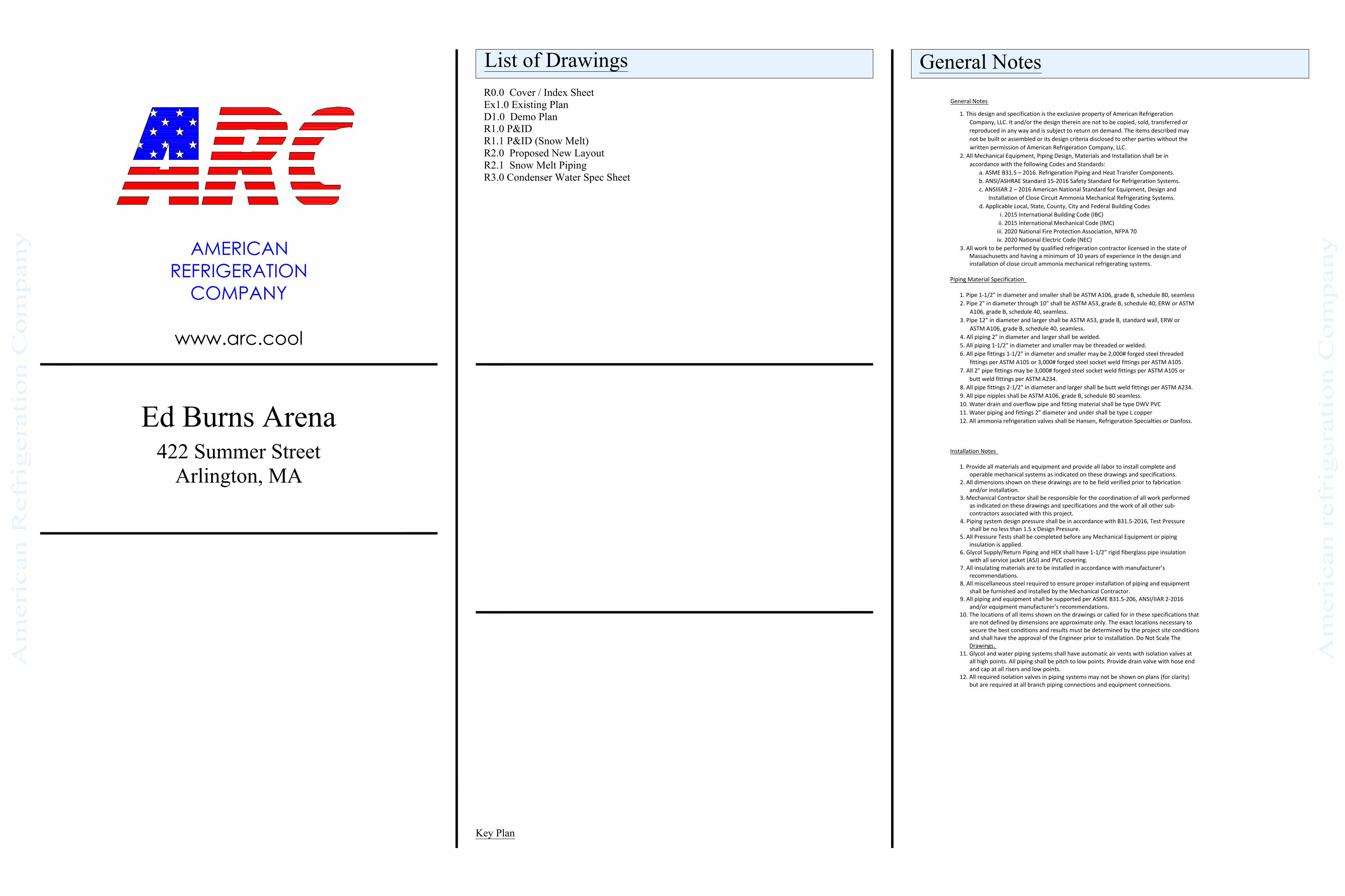
Arlington Ice RinkCondenser Water& Jacket Clg P&ID
AutoCAD SHX Text
TO EVAPORATIVE CONDENSER
AutoCAD SHX Text
FROM EVAPORATIVE CONDENSER
AutoCAD SHX Text
CONDENSER WATER SUPPLY TANK
AutoCAD SHX Text
TO RCP-2 WATER JACKET
AutoCAD SHX Text
FROM RCP-2 WATER JACKET
AutoCAD SHX Text
TO RCP-1 WATER JACKET
AutoCAD SHX Text
FROM RCP-1 WATER JACKET
AutoCAD SHX Text
CITY WATER SUPPLY WITH BACK FLOW
AutoCAD SHX Text
CONDENSER WATER SUPPLY PUMPS
AutoCAD SHX Text
COMPRESSOR JACKET COOLING PUMPS
AutoCAD SHX Text
B & G E-1532 3AD
AutoCAD SHX Text
GOULD'S 5SV6GA8C60
AutoCAD SHX Text
PK
AutoCAD SHX Text
AMERICAN REFRIGERATION COMPANY
AutoCAD SHX Text
1
AutoCAD SHX Text
4-9-20
AutoCAD SHX Text
ORIGINAL ISSUE
AutoCAD SHX Text
HL ALARM (42")
AutoCAD SHX Text
REF (0")
AutoCAD SHX Text
OPER LEVEL (28")
AutoCAD SHX Text
LOW LEVEL (25")
AutoCAD SHX Text
GROUND (6")
AutoCAD SHX Text
6" PUMP SUCTION HEADER
AutoCAD SHX Text
4"
AutoCAD SHX Text
4"
AutoCAD SHX Text
1-1/4"
AutoCAD SHX Text
1-1/4"
AutoCAD SHX Text
3"
AutoCAD SHX Text
3"
AutoCAD SHX Text
1-1/4"
AutoCAD SHX Text
1-1/4"
AutoCAD SHX Text
1-1/4" (7 - 14 GPM)
AutoCAD SHX Text
1-1/4" (7 - 14 GPM)
AutoCAD SHX Text
3/4" (7 GPM)
AutoCAD SHX Text
3/4" (7 GPM)
AutoCAD SHX Text
3/4" (7 GPM)
AutoCAD SHX Text
3/4" (7 GPM)
AutoCAD SHX Text
4" (220 GPM)
AutoCAD SHX Text
6"
AutoCAD SHX Text
3/4" WATER MAKE-UP
AutoCAD SHX Text
3/4" BLEED
AutoCAD SHX Text
3/4"
AutoCAD SHX Text
3/4"
AutoCAD SHX Text
3/4" BY-PASS
AutoCAD SHX Text
3/4"
AutoCAD SHX Text
1-1/4" (7 GPM)
AutoCAD SHX Text
1-1/4" (7 GPM)
AutoCAD SHX Text
1. ALL WATER PIPING 2" NPS AND OVER SHALL BE SCH40, A53 GRADE B, ERW. 2. ALL STEEL PIPING 2" NPS AND OVER SHALL BE JOINED BE MEANS OF WELDING. 3. ALL DRAIN AND OVERFLOW PIPING SHALL BE SCH40 DWV PVC. 4. ALL WATER PIPING 1-1/2" NPS AND UNDER SHALL BE TYPE L COPPER TUBE AND FITTINGS. COPPER TUBE AND FITTINGS SHALL BE JOINED BY MEANS OF SOLDERING. USE OF VIEGA PRO-PRESS FITTINGS IS ALSO ACCEPTABLE. 5. ALL BALL VALVES SHALL BE APOLLO SERIES 70-100, 2 PIECE BRONZE BODY VALVES (OR EQUAL). 6. ALL BUTTERFLY VALVES SHALL BE APOLLO LUG TYPE BUTTERFLY VALVES (OR EQUAL). 7. ALL PUMP DISCHARGE PIPING SHALL HAVE 3.5" DIA. FACE, 0-60PSI, LIQUID FILLED INDUSTRIAL GRADE PRESSURE GAUGE. PRESSURE GAUGE ISOLATION BALL VALVE SHALL BE 1/2". 8. COMPRESSOR JACKET COOLING PUMPS TO BE FITTED WITH KECKLEY STYLE KT-7 (OR EQUAL) BASKET STRAINER SIZE 1-1/2" WITH 100 MESH SCREEN.
AutoCAD SHX Text
GENERAL NOTES:
AutoCAD SHX Text
STRAINER
AutoCAD SHX Text
STRAINER
Rev
.
Drf./Det./Chk.:
SCALE:
DATE:
Dat
eR
evis
ion
Des
crip
tion
ARLIN
GTON
ICE R
INK
REFR
IGER
ATIO
N SY
STEM
UPG
RADE
S
422 S
UMM
ER ST
,AR
LINGT
ON, M
A
WO - 072609
5th March 2020
Chk
This drawing and the information included on itare the property of ARC LLC. Any reproduction,distribution, or manipulation is strictly prohibted
without the written consent ofARC Companies.
www.arc.cool
149 RIVER STREETSUITE # 3
ANDOVER, MA 01810 t 987-474-4000f 978-474-4001
Client Logo/Seal
R1.1ED
NTS
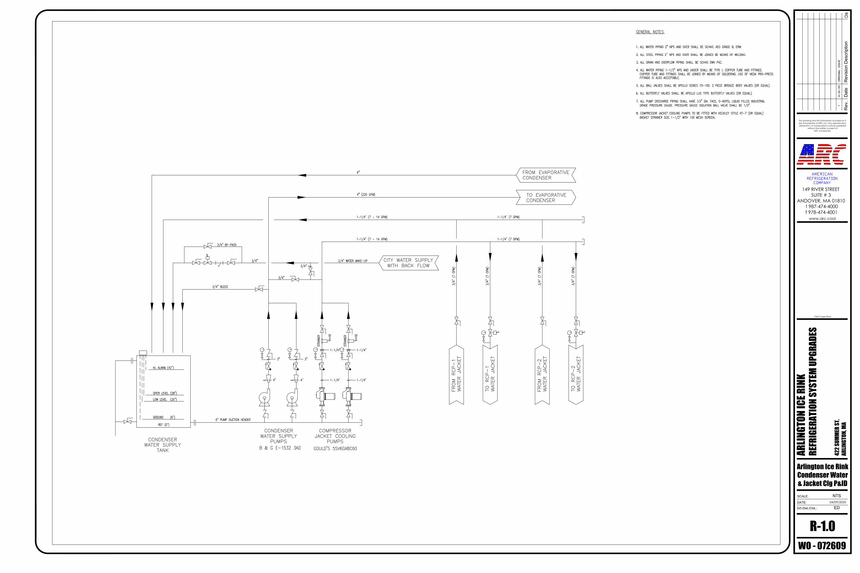
Arlington Ice RinkSNOW MELT
P&ID
AutoCAD SHX Text
RELIEF HEADER
AutoCAD SHX Text
RELIEF
AutoCAD SHX Text
SNOWMELT HEX
AutoCAD SHX Text
CONC.
AutoCAD SHX Text
ECC.
AutoCAD SHX Text
PI
AutoCAD SHX Text
0 TO 100 PSI
AutoCAD SHX Text
BRZ
AutoCAD SHX Text
BRZ
AutoCAD SHX Text
FROM COMPRESSOR
AutoCAD SHX Text
FROM MACHINE ROOM
AutoCAD SHX Text
COLMAC COIL BWR-45x62.0-4R
AutoCAD SHX Text
HSD
AutoCAD SHX Text
HSD
AutoCAD SHX Text
%%U(x) EC-1
AutoCAD SHX Text
FROM REMOTE SUMP
AutoCAD SHX Text
TO ICE RINK CHILLER
AutoCAD SHX Text
HSD
AutoCAD SHX Text
RELIEF HEADER
AutoCAD SHX Text
HANSEN H5600RD, 1/2" X 3/4" 17 LBS AIR/MIN @ 250PSIG
AutoCAD SHX Text
1-1/4" SRV
AutoCAD SHX Text
TO REMOTE SUMP
AutoCAD SHX Text
2" GS
AutoCAD SHX Text
2" GS
AutoCAD SHX Text
2" GR
AutoCAD SHX Text
2" GR
AutoCAD SHX Text
CWS
AutoCAD SHX Text
2" GR
AutoCAD SHX Text
VENT
AutoCAD SHX Text
B&G EAS-2 AIR SEPERATOR
AutoCAD SHX Text
B&G MODEL D-40V EXPANSION TANK
AutoCAD SHX Text
B&G MODEL GMU-30 GLYCOL MAKE-UP UNIT
AutoCAD SHX Text
B&G E-90 MODEL 1.25 AAB SNOW MELT COIL CIRCULATING PUMP
AutoCAD SHX Text
1"
AutoCAD SHX Text
3/4" GMU
AutoCAD SHX Text
PK
AutoCAD SHX Text
AMERICAN REFRIGERATION COMPANY
AutoCAD SHX Text
00
AutoCAD SHX Text
04.24.20
AutoCAD SHX Text
Issued For Bid
AutoCAD SHX Text
GENERAL NOTES: 1. SNOW MELT CLOSED LOOP CIRCULATING SYSTEM TO BE FILLED WITH 30% INHIBITED PROPYLENE GLYCOL. 2. SYSTEM VOLUME APPROXIMATELY 120 GALLONS.
M
BA
C
Rev
.
Drf./Det./Chk.:
SCALE:
DATE:
Dat
eR
evis
ion
Des
crip
tion
Arlin
gton
Ice R
ink
Refri
gera
tion S
yste
m U
pdat
es
422 S
umm
er St
reet
Arlin
gton
, MA
WO-072609
5th March 2020
Chk
This drawing and the information included on itare the property of ARC LLC. Any reproduction,distribution, or manipulation is strictly prohibted
without the written consent ofARC Companies.
www.arc.cool
149 RIVER STREETSUITE # 3
ANDOVER, MA 01810 t 987-474-4000f 978-474-4001
Client Logo/Seal
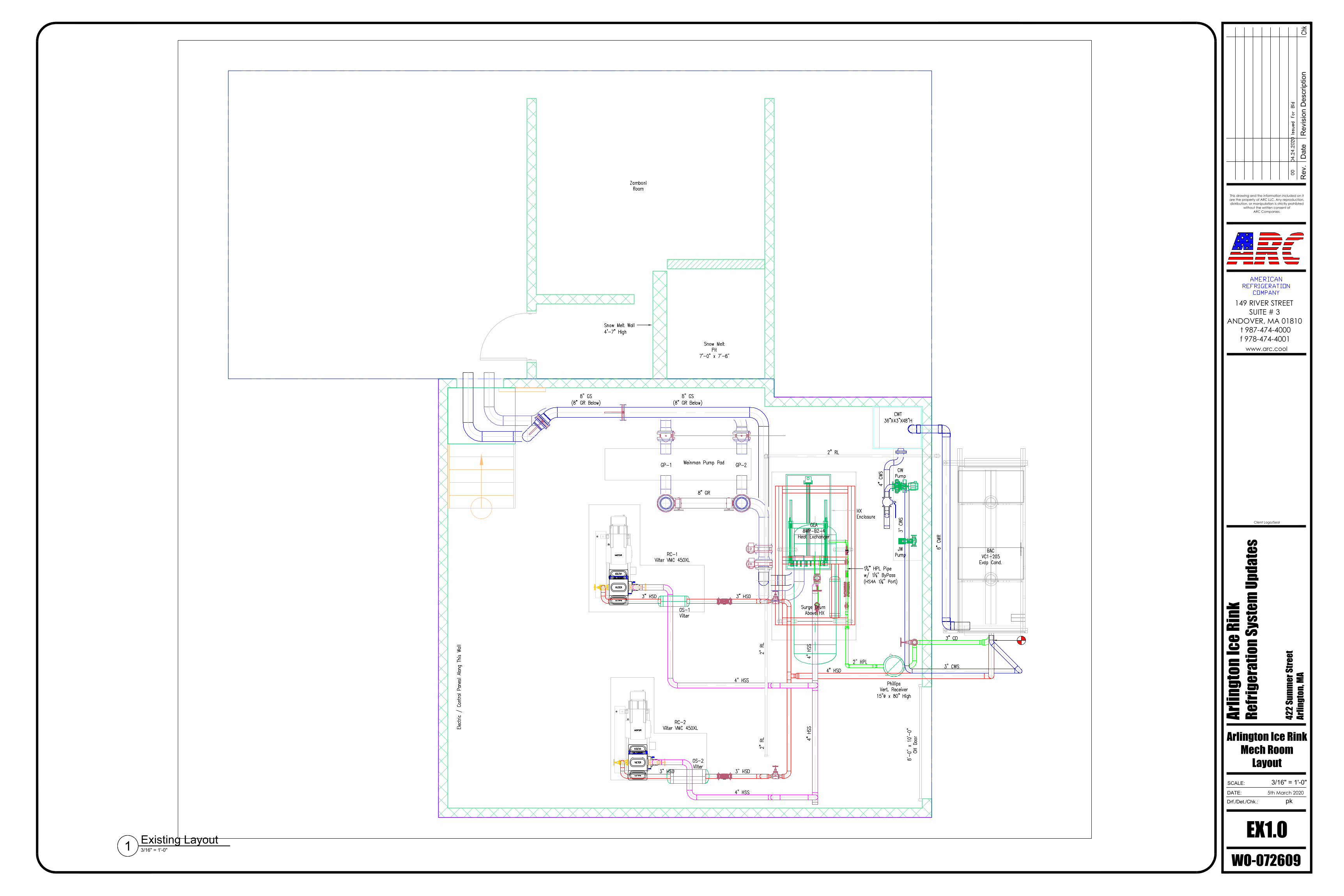
EX1.0pk
3/16" = 1'-0"
Arlington Ice RinkMech Room
Layout
Existing Layout3/16" = 1'-0"1
AutoCAD SHX Text
OIL COOLER
AutoCAD SHX Text
VILTER
AutoCAD SHX Text
VILTER
AutoCAD SHX Text
VILTER
AutoCAD SHX Text
MOTOR
AutoCAD SHX Text
OIL COOLER
AutoCAD SHX Text
VILTER
AutoCAD SHX Text
VILTER
AutoCAD SHX Text
VILTER
AutoCAD SHX Text
MOTOR
AutoCAD SHX Text
PK
AutoCAD SHX Text
AMERICAN REFRIGERATION COMPANY
AutoCAD SHX Text
00
AutoCAD SHX Text
04.24.2020
AutoCAD SHX Text
Issued For Bid
AutoCAD SHX Text
Snow Melt Pit 7'-0" x 7'-8"
AutoCAD SHX Text
Snow Melt Wall 4'-7" High
AutoCAD SHX Text
CWT 36"X43"X48"H
AutoCAD SHX Text
RC-1 Vilter VMC 450XL
AutoCAD SHX Text
RC-2 Vilter VMC 450XL
AutoCAD SHX Text
Weinman Pump Pad
AutoCAD SHX Text
GEA 8WP-B2-4 Heat Exchanger
AutoCAD SHX Text
BAC VC1-205 Evap Cond.
AutoCAD SHX Text
Zamboni Room
AutoCAD SHX Text
Phillips Vert. Receiver 15" x 80" High
AutoCAD SHX Text
Surge Drum Above HX
AutoCAD SHX Text
HX Enclosure
AutoCAD SHX Text
8'-0" x 10'-0" OH Door
AutoCAD SHX Text
Electric / Control Panesl Along This Wall
AutoCAD SHX Text
3" HSD
AutoCAD SHX Text
3" HSD
AutoCAD SHX Text
4" HSS
AutoCAD SHX Text
4" HSS
AutoCAD SHX Text
4" HSD
AutoCAD SHX Text
4" HSS
AutoCAD SHX Text
4" HSS
AutoCAD SHX Text
3" HSD
AutoCAD SHX Text
3" HSD
AutoCAD SHX Text
3" CD
AutoCAD SHX Text
3" CWS
AutoCAD SHX Text
2" HPL
AutoCAD SHX Text
1 " HPL Pipe 14" HPL Pipe w/ 1 " ByPass 14" ByPass (HS4A 1 " Port)14" Port)
AutoCAD SHX Text
6" CWR
AutoCAD SHX Text
3" CWS
AutoCAD SHX Text
8" GR
AutoCAD SHX Text
8" GS (8" GR Below)
AutoCAD SHX Text
8" GS (8" GR Below)
AutoCAD SHX Text
4" CWS
AutoCAD SHX Text
CW Pump
AutoCAD SHX Text
2" RL
AutoCAD SHX Text
2" RL
AutoCAD SHX Text
2" RL
AutoCAD SHX Text
GP-1
AutoCAD SHX Text
GP-2
AutoCAD SHX Text
OS-1 Vilter
AutoCAD SHX Text
OS-2 Vilter
AutoCAD SHX Text
JW Pump
M
BA
C
Rev
.
Drf./Det./Chk.:
SCALE:
DATE:
Dat
eR
evis
ion
Des
crip
tion
Arlin
gton
Ice R
ink
Refri
gera
tion S
yste
m U
pdat
es
422 S
umm
er St
reet
Arlin
gton
, MA
WO-072609
5th March 2020
Chk
This drawing and the information included on itare the property of ARC LLC. Any reproduction,distribution, or manipulation is strictly prohibted
without the written consent ofARC Companies.
www.arc.cool
149 RIVER STREETSUITE # 3
ANDOVER, MA 01810 t 987-474-4000f 978-474-4001
Client Logo/Seal
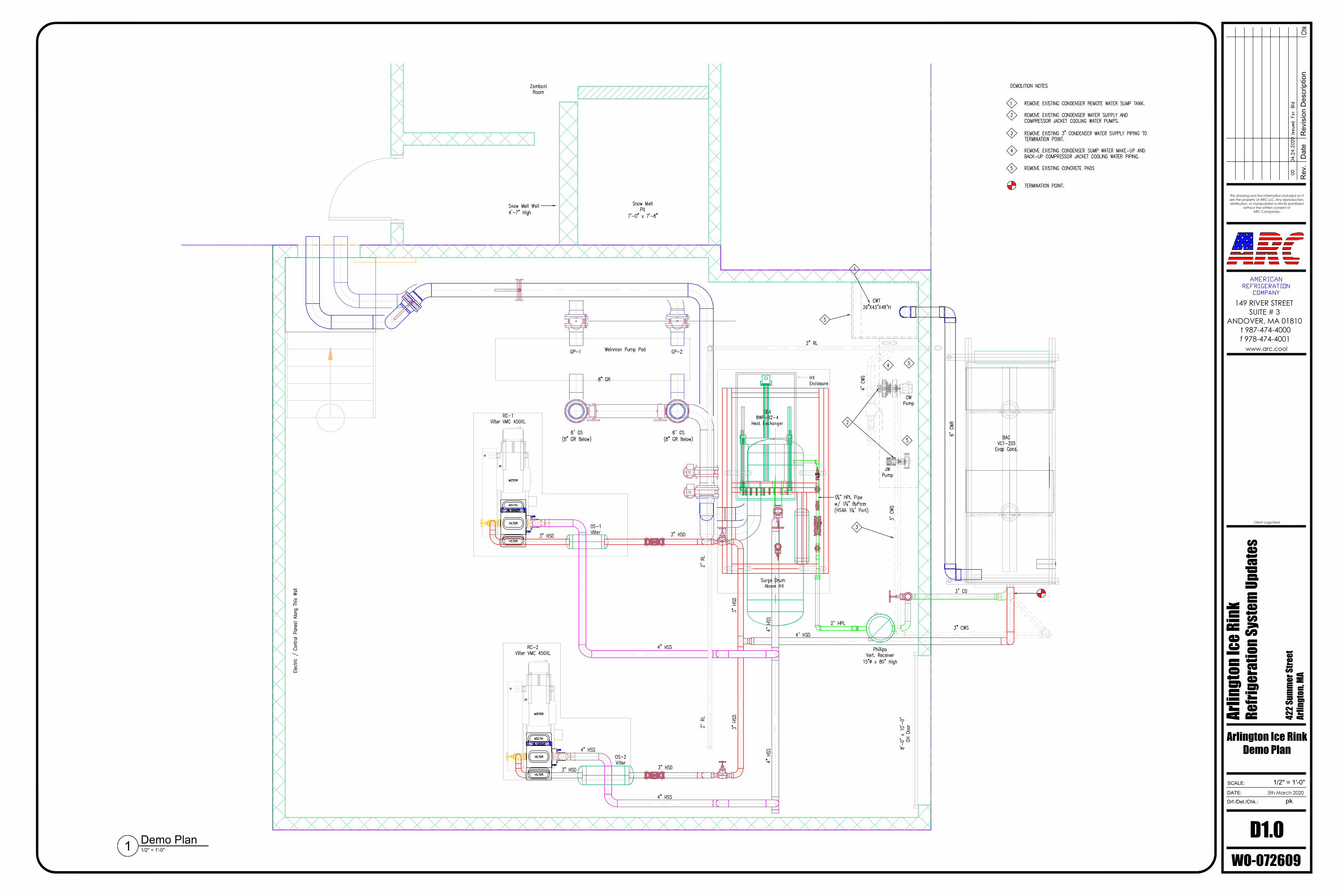
D1.0pk
1/2" = 1'-0"
Arlington Ice RinkDemo Plan
Demo Plan1/2" = 1'-0"1
AutoCAD SHX Text
OIL COOLER
AutoCAD SHX Text
VILTER
AutoCAD SHX Text
VILTER
AutoCAD SHX Text
VILTER
AutoCAD SHX Text
MOTOR
AutoCAD SHX Text
OIL COOLER
AutoCAD SHX Text
VILTER
AutoCAD SHX Text
VILTER
AutoCAD SHX Text
VILTER
AutoCAD SHX Text
MOTOR
AutoCAD SHX Text
PK
AutoCAD SHX Text
AMERICAN REFRIGERATION COMPANY
AutoCAD SHX Text
00
AutoCAD SHX Text
04.24.2020
AutoCAD SHX Text
Issued For Bid
AutoCAD SHX Text
Snow Melt Pit 7'-0" x 7'-8"
AutoCAD SHX Text
Snow Melt Wall 4'-7" High
AutoCAD SHX Text
CWT 36"X43"X48"H
AutoCAD SHX Text
RC-1 Vilter VMC 450XL
AutoCAD SHX Text
RC-2 Vilter VMC 450XL
AutoCAD SHX Text
Weinman Pump Pad
AutoCAD SHX Text
GEA 8WP-B2-4 Heat Exchanger
AutoCAD SHX Text
BAC VC1-205 Evap Cond.
AutoCAD SHX Text
Zamboni Room
AutoCAD SHX Text
Phillips Vert. Receiver 15" x 80" High
AutoCAD SHX Text
Surge Drum Above HX
AutoCAD SHX Text
HX Enclosure
AutoCAD SHX Text
8'-0" x 10'-0" OH Door
AutoCAD SHX Text
Electric / Control Panesl Along This Wall
AutoCAD SHX Text
3" HSD
AutoCAD SHX Text
3" HSD
AutoCAD SHX Text
4" HSS
AutoCAD SHX Text
4" HSS
AutoCAD SHX Text
4" HSD
AutoCAD SHX Text
4" HSS
AutoCAD SHX Text
4" HSS
AutoCAD SHX Text
3" HSD
AutoCAD SHX Text
3" HSD
AutoCAD SHX Text
3" CD
AutoCAD SHX Text
3" CWS
AutoCAD SHX Text
2" HPL
AutoCAD SHX Text
1 " HPL Pipe 14" HPL Pipe w/ 1 " ByPass 14" ByPass (HS4A 1 " Port)14" Port)
AutoCAD SHX Text
6" CWR
AutoCAD SHX Text
3" CWS
AutoCAD SHX Text
8" GR
AutoCAD SHX Text
8" GS (8" GR Below)
AutoCAD SHX Text
8" GS (8" GR Below)
AutoCAD SHX Text
4" CWS
AutoCAD SHX Text
CW Pump
AutoCAD SHX Text
2" RL
AutoCAD SHX Text
2" RL
AutoCAD SHX Text
GP-1
AutoCAD SHX Text
GP-2
AutoCAD SHX Text
OS-1 Vilter
AutoCAD SHX Text
OS-2 Vilter
AutoCAD SHX Text
DEMOLITION NOTES 1 REMOVE EXISTING CONDENSER REMOTE WATER SUMP TANK. REMOVE EXISTING CONDENSER REMOTE WATER SUMP TANK. 2 REMOVE EXISTING CONDENSER WATER SUPPLY AND REMOVE EXISTING CONDENSER WATER SUPPLY AND COMPRESSOR JACKET COOLING WATER PUMPS. 3 REMOVE EXISTING 3" CONDENSER WATER SUPPLY PIPING TO REMOVE EXISTING 3" CONDENSER WATER SUPPLY PIPING TO TERMINATION POINT. 4 REMOVE EXISTING CONDENSER SUMP WATER MAKE-UP AND REMOVE EXISTING CONDENSER SUMP WATER MAKE-UP AND BACK-UP COMPRESSOR JACKET COOLING WATER PIPING. 5 REMOVE EXISTING CONCRETE PADS REMOVE EXISTING CONCRETE PADS TERMINATION POINT.
AutoCAD SHX Text
5
AutoCAD SHX Text
1
AutoCAD SHX Text
4
AutoCAD SHX Text
5
AutoCAD SHX Text
5
AutoCAD SHX Text
3
AutoCAD SHX Text
2
AutoCAD SHX Text
JW Pump
AutoCAD SHX Text
2" RL
AutoCAD SHX Text
4" HSS
AutoCAD SHX Text
3" HSD
AutoCAD SHX Text
3" HSD
M
BA
C
Rev
.
Drf./Det./Chk.:
SCALE:
DATE:
Dat
eR
evis
ion
Des
crip
tion
Arlin
gton
Ice R
ink
Refri
gera
tion S
yste
m U
pdat
es
422 S
umm
er St
reet
Arlin
gton
, MA
WO-072609
5th March 2020
Chk
This drawing and the information included on itare the property of ARC LLC. Any reproduction,distribution, or manipulation is strictly prohibted
without the written consent ofARC Companies.
www.arc.cool
149 RIVER STREETSUITE # 3
ANDOVER, MA 01810 t 987-474-4000f 978-474-4001
Client Logo/Seal
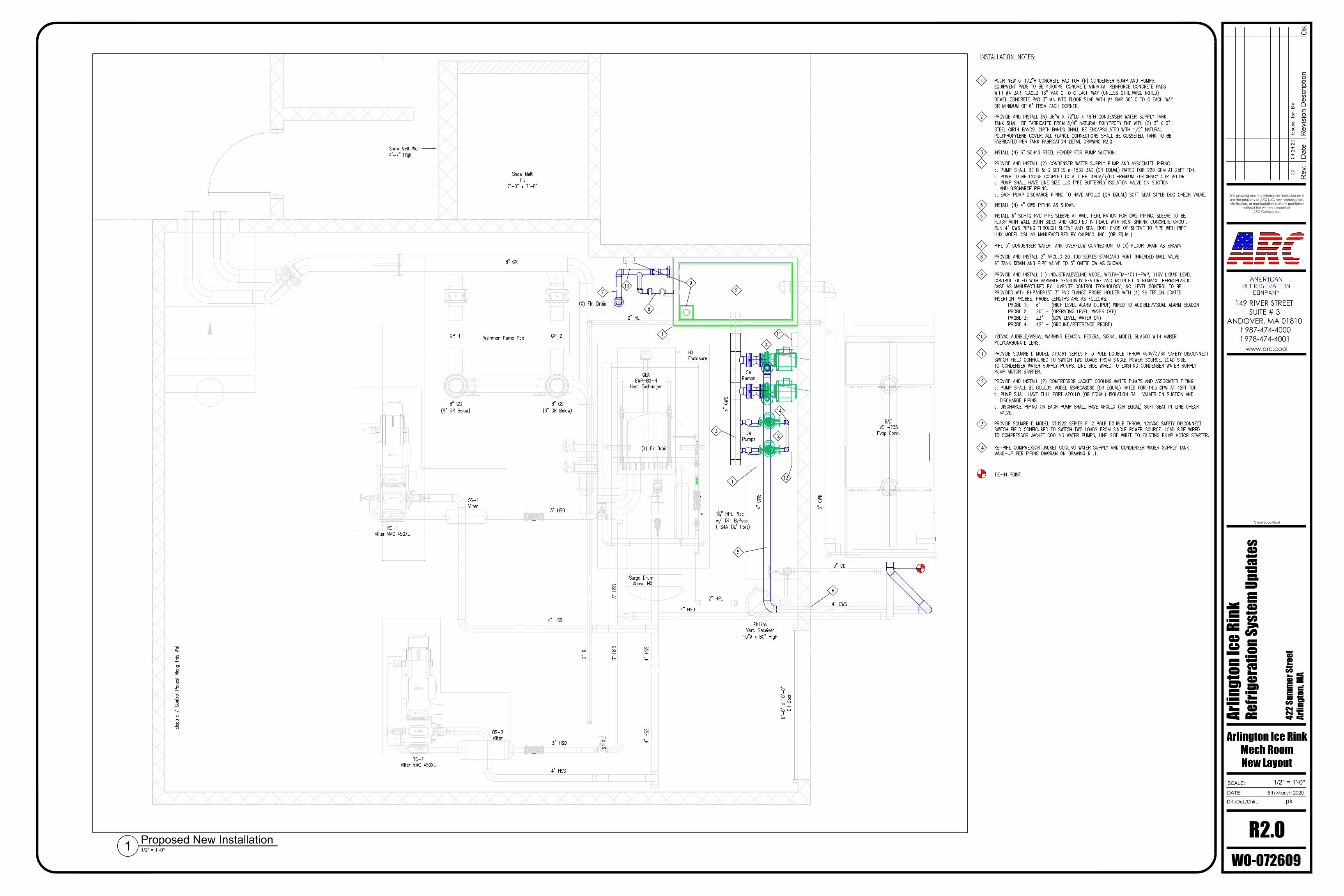
R2.0pk
1/2" = 1'-0"
Arlington Ice RinkMech RoomNew Layout
Proposed New Installation1/2" = 1'-0"1
AutoCAD SHX Text
OIL COOLER
AutoCAD SHX Text
VILTER
AutoCAD SHX Text
VILTER
AutoCAD SHX Text
VILTER
AutoCAD SHX Text
MOTOR
AutoCAD SHX Text
OIL COOLER
AutoCAD SHX Text
VILTER
AutoCAD SHX Text
VILTER
AutoCAD SHX Text
VILTER
AutoCAD SHX Text
MOTOR
AutoCAD SHX Text
PK
AutoCAD SHX Text
AMERICAN REFRIGERATION COMPANY
AutoCAD SHX Text
00
AutoCAD SHX Text
04.24.20
AutoCAD SHX Text
Issued for Bid
AutoCAD SHX Text
Snow Melt Pit 7'-0" x 7'-8"
AutoCAD SHX Text
Snow Melt Wall 4'-7" High
AutoCAD SHX Text
RC-1 Vilter VMC 450XL
AutoCAD SHX Text
RC-2 Vilter VMC 450XL
AutoCAD SHX Text
Weinman Pump Pad
AutoCAD SHX Text
GEA 8WP-B2-4 Heat Exchanger
AutoCAD SHX Text
BAC VC1-205 Evap Cond.
AutoCAD SHX Text
Phillips Vert. Receiver 15" x 80" High
AutoCAD SHX Text
Surge Drum Above HX
AutoCAD SHX Text
HX Enclosure
AutoCAD SHX Text
8'-0" x 10'-0" OH Door
AutoCAD SHX Text
Electric / Control Panesl Along This Wall
AutoCAD SHX Text
3" HSD
AutoCAD SHX Text
4" HSS
AutoCAD SHX Text
4" HSS
AutoCAD SHX Text
4" HSD
AutoCAD SHX Text
4" HSS
AutoCAD SHX Text
4" HSS
AutoCAD SHX Text
3" HSD
AutoCAD SHX Text
3" CD
AutoCAD SHX Text
4" CWS
AutoCAD SHX Text
2" HPL
AutoCAD SHX Text
1 " HPL Pipe 14" HPL Pipe w/ 1 " ByPass 14" ByPass (HS4A 1 " Port)14" Port)
AutoCAD SHX Text
6" CWR
AutoCAD SHX Text
4" CWS
AutoCAD SHX Text
8" GR
AutoCAD SHX Text
8" GS (8" GR Below)
AutoCAD SHX Text
8" GS (8" GR Below)
AutoCAD SHX Text
6" CWS
AutoCAD SHX Text
CW Pumps
AutoCAD SHX Text
2" RL
AutoCAD SHX Text
2" RL
AutoCAD SHX Text
2" RL
AutoCAD SHX Text
GP-1
AutoCAD SHX Text
GP-2
AutoCAD SHX Text
OS-1 Vilter
AutoCAD SHX Text
OS-2 Vilter
AutoCAD SHX Text
3" HSD
AutoCAD SHX Text
3" HSD
AutoCAD SHX Text
1 POUR NEW 5-1/2"H CONCRETE PAD FOR (N) CONDENSER SUMP AND PUMPS. POUR NEW 5-1/2"H CONCRETE PAD FOR (N) CONDENSER SUMP AND PUMPS. EQUIPMENT PADS TO BE 4,000PSI CONCRETE MINIMUM. REINFORCE CONCRETE PADS WITH #4 BAR PLACED 18" MAX C TO C EACH WAY (UNLESS OTHERWISE NOTED) DOWEL CONCRETE PAD 3" MN INTO FLOOR SLAB WITH #4 BAR 36" C TO C EACH WAY OR MINIMUM OF 6" FROM EACH CORNER.
AutoCAD SHX Text
INSTALLATION NOTES:
AutoCAD SHX Text
TIE-IN POINT
AutoCAD SHX Text
2 PROVIDE AND INSTALL (N) 36"W X 72"LG X 48"H CONDENSER WATER SUPPLY TANK. PROVIDE AND INSTALL (N) 36"W X 72"LG X 48"H CONDENSER WATER SUPPLY TANK. TANK SHALL BE FABRICATED FROM 3/4" NATURAL POLYPROPYLENE WITH (2) 3" X 3" STEEL GIRTH BANDS. GIRTH BANDS SHALL BE ENCAPSULATED WITH 1/2" NATURAL POLYPROPYLENE COVER. ALL FLANGE CONNECTIONS SHALL BE GUSSETED. TANK TO BE FABRICATED PER TANK FABRICATION DETAIL DRAWING R3.0
AutoCAD SHX Text
3 INSTALL (N) 6" SCH40 STEEL HEADER FOR PUMP SUCTION. INSTALL (N) 6" SCH40 STEEL HEADER FOR PUMP SUCTION.
AutoCAD SHX Text
4 PROVIDE AND INSTALL (2) CONDENSER WATER SUPPLY PUMP AND ASSOCIATED PIPING. PROVIDE AND INSTALL (2) CONDENSER WATER SUPPLY PUMP AND ASSOCIATED PIPING. a. PUMP SHALL BE B & G SETIES e-1532 3AD (OR EQUAL) RATED FOR 220 GPM AT 25FT TDH. b. PUMP TO BE CLOSE COUPLED TO A 3 HP, 480V/3/60 PREMIUM EFFICIENCY ODP MOTOR. c. PUMP SHALL HAVE LINE SIZE LUG TYPE BUTTERFLY ISOLATION VALVE ON SUCTION AND DISCHARGE PIPING. d. EACH PUMP DISCHARGE PIPING TO HAVE APOLLO (OR EQUAL) SOFT SEAT STYLE DUO CHECK VALVE.
AutoCAD SHX Text
5 INSTALL (N) 4" CWS PIPING AS SHOWN. INSTALL (N) 4" CWS PIPING AS SHOWN.
AutoCAD SHX Text
6 INSTALL 6" SCH40 PVC PIPE SLEEVE AT WALL PENETRATION FOR CWS PIPING. SLEEVE TO BE INSTALL 6" SCH40 PVC PIPE SLEEVE AT WALL PENETRATION FOR CWS PIPING. SLEEVE TO BE FLUSH WITH WALL BOTH SIDES AND GROUTED IN PLACE WITH NON-SHRINK CONCRETE GROUT. RUN 4" CWS PIPING THROUGH SLEEVE AND SEAL BOTH ENDS OF SLEEVE TO PIPE WITH PIPE LINX MODEL CSL AS MANUFACTURED BY CALPICO, INC. (OR EQUAL).
AutoCAD SHX Text
7 PIPE 3" CONDENSER WATER TANK OVERFLOW CONNECTION TO (X) FLOOR DRAIN AS SHOWN. PIPE 3" CONDENSER WATER TANK OVERFLOW CONNECTION TO (X) FLOOR DRAIN AS SHOWN.
AutoCAD SHX Text
8 PROVIDE AND INSTALL 2" APOLLO 20-100 SERIES STANDARD PORT THREADED BALL VALVE PROVIDE AND INSTALL 2" APOLLO 20-100 SERIES STANDARD PORT THREADED BALL VALVE AT TANK DRAIN AND PIPE VALVE TO 3" OVERFLOW AS SHOWN.
AutoCAD SHX Text
9 PROVIDE AND INSTALL (1) INDUSTRIALEVELINE MODEL WFLTV-TM-4011-PWP, 110V LIQUID LEVEL PROVIDE AND INSTALL (1) INDUSTRIALEVELINE MODEL WFLTV-TM-4011-PWP, 110V LIQUID LEVEL CONTROL FITTED WITH VARIABLE SENSITIVITY FEATURE AND MOUNTED IN NEMA4X THERMOPLASTIC CASE AS MANUFACTURED BY LUMENITE CONTROL TECHNOLOGY, INC. LEVEL CONTROL TO BE PROVIDED WITH PHP34EP15T 3" PVC FLANGE PROBE HOLDER WITH (4) SS TEFLON COATED INSERTION PROBES. PROBE LENGTHS ARE AS FOLLOWS; PROBE 1: 6" - (HIGH LEVEL ALARM OUTPUT) WIRED TO AUDIBLE/VISUAL ALARM BEACON 6" - (HIGH LEVEL ALARM OUTPUT) WIRED TO AUDIBLE/VISUAL ALARM BEACON PROBE 2: 20" - (OPERATING LEVEL, WATER OFF) 20" - (OPERATING LEVEL, WATER OFF) PROBE 3: 23" - (LOW LEVEL, WATER ON) 23" - (LOW LEVEL, WATER ON) PROBE 4: 42" - (GROUND/REFERENCE PROBE) 42" - (GROUND/REFERENCE PROBE)
AutoCAD SHX Text
120VAC AUDIBLE/VISUAL WARNING BEACON. FEDERAL SIGNAL MODEL SLM600 WITH AMBER 120VAC AUDIBLE/VISUAL WARNING BEACON. FEDERAL SIGNAL MODEL SLM600 WITH AMBER POLYCARBONATE LENS.
AutoCAD SHX Text
10
AutoCAD SHX Text
PROVIDE SQUARE D MODEL DTU361 SERIES F, 3 POLE DOUBLE THROW 460V/3/60 SAFETY DISCONNECT PROVIDE SQUARE D MODEL DTU361 SERIES F, 3 POLE DOUBLE THROW 460V/3/60 SAFETY DISCONNECT SWITCH FIELD CONFIGURED TO SWITCH TWO LOADS FROM SINGLE POWER SOURCE. LOAD SIDE TO CONDENSER WATER SUPPLY PUMPS, LINE SIDE WIRED TO EXISTING CONDENSER WATER SUPPLY PUMP MOTOR STARTER.
AutoCAD SHX Text
11
AutoCAD SHX Text
PROVIDE AND INSTALL (2) COMPRESSOR JACKET COOLING WATER PUMPS AND ASSOCIATED PIPING. PROVIDE AND INSTALL (2) COMPRESSOR JACKET COOLING WATER PUMPS AND ASSOCIATED PIPING. a. PUMP SHALL BE GOULDS MODEL 5SV6GA8C60 (OR EQUAL) RATED FOR 14.5 GPM AT 42FT TDH. b. PUMP SHALL HAVE FULL PORT APOLLO (OR EQUAL) ISOLATION BALL VALVES ON SUCTION AND DISCHARGE PIPING c. DISCHARGE PIPING ON EACH PUMP SHALL HAVE APOLLO (OR EQUAL) SOFT SEAT IN-LINE CHECK VALVE.
AutoCAD SHX Text
12
AutoCAD SHX Text
PROVIDE SQUARE D MODEL DTU222 SERIES F, 2 POLE DOUBLE THROW, 120VAC SAFETY DISCONNECT PROVIDE SQUARE D MODEL DTU222 SERIES F, 2 POLE DOUBLE THROW, 120VAC SAFETY DISCONNECT SWITCH FIELD CONFIGURED TO SWITCH TWO LOADS FROM SINGLE POWER SOURCE. LOAD SIDE WIRED TO COMPRESSOR JACKET COOLING WATER PUMPS, LINE SIDE WIRED TO EXISTING PUMP MOTOR STARTER.
AutoCAD SHX Text
13
AutoCAD SHX Text
RE-PIPE COMPRESSOR JACKET COOLING WATER SUPPLY AND CONDENSER WATER SUPPLY TANK RE-PIPE COMPRESSOR JACKET COOLING WATER SUPPLY AND CONDENSER WATER SUPPLY TANK MAKE-UP PER PIPING DIAGRAM ON DRAWING R1.1.
AutoCAD SHX Text
14
AutoCAD SHX Text
8
AutoCAD SHX Text
1
AutoCAD SHX Text
2
AutoCAD SHX Text
3
AutoCAD SHX Text
4
AutoCAD SHX Text
5
AutoCAD SHX Text
6
AutoCAD SHX Text
7
AutoCAD SHX Text
1
AutoCAD SHX Text
9
AutoCAD SHX Text
10
AutoCAD SHX Text
11
AutoCAD SHX Text
12
AutoCAD SHX Text
JW Pumps
AutoCAD SHX Text
13
AutoCAD SHX Text
(X) Flr Drain
AutoCAD SHX Text
(X) Flr. Drain
AutoCAD SHX Text
14

M
BA
C
Rev
.
Drf./Det./Chk.:
SCALE:
DATE:
Dat
eR
evis
ion
Des
crip
tion
Arlin
gton
Ice R
ink
Refri
gera
tion S
yste
m U
pdat
es
422 S
umm
er St
reet
Arlin
gton
, MA
WO-072609
5th March 2020
Chk
This drawing and the information included on itare the property of ARC LLC. Any reproduction,distribution, or manipulation is strictly prohibted
without the written consent ofARC Companies.
www.arc.cool
149 RIVER STREETSUITE # 3
ANDOVER, MA 01810 t 987-474-4000f 978-474-4001
Client Logo/Seal
R2.1pk
As Noted
Arlington Ice RinkSnow Melt
Plan
AutoCAD SHX Text
OIL COOLER
AutoCAD SHX Text
VILTER
AutoCAD SHX Text
VILTER
AutoCAD SHX Text
VILTER
AutoCAD SHX Text
MOTOR
AutoCAD SHX Text
OIL COOLER
AutoCAD SHX Text
VILTER
AutoCAD SHX Text
VILTER
AutoCAD SHX Text
VILTER
AutoCAD SHX Text
MOTOR
AutoCAD SHX Text
PK
AutoCAD SHX Text
AMERICAN REFRIGERATION COMPANY
AutoCAD SHX Text
00
AutoCAD SHX Text
04.24.20
AutoCAD SHX Text
Issued for Bid
AutoCAD SHX Text
2" GS
AutoCAD SHX Text
2" GS
AutoCAD SHX Text
2" GS
AutoCAD SHX Text
2" GR
AutoCAD SHX Text
2" GR
AutoCAD SHX Text
2" GS
AutoCAD SHX Text
2" GS
AutoCAD SHX Text
1 " RL14" RL
AutoCAD SHX Text
1 INFILL FRONT WALL OF EXISTING SNOW MELT PIT TO COMPLETELY ENCLOSE PIT AND BRING WALL INFILL FRONT WALL OF EXISTING SNOW MELT PIT TO COMPLETELY ENCLOSE PIT AND BRING WALL HEIGHT TO 40" ABOVE FINISHED FLOOR. MATCH EXISTING CMU CONSTRUCTION AND FILL ALL OPEN CORES WITH #5 BAR AND MORTAR TO STRENGTHEN WALL. TO BE LEFT SMOOTH AND LEVEL.
AutoCAD SHX Text
INSTALLATION NOTES:
AutoCAD SHX Text
2 AFTER CONCRETE REPAIRS TO SNOW MELT PIT ARE COMPLETE AND 3" OVERFLOW PIPE (SEE NOTE 4) AFTER CONCRETE REPAIRS TO SNOW MELT PIT ARE COMPLETE AND 3" OVERFLOW PIPE (SEE NOTE 4) INSTALLED, SEAL FLOOR, WALLS AND TOP OF FRONT WALL OF SNOW MELT PIT WITH DURA-RUBBER LIQUID RUBBER COATING SYSTEM (OR EQUAL). SIDE AND BACK WALL TO BE COATED TO A HEIGHT OF 48" ABOVE FLOOR. DURA-RUBBER LIQUID RUBBER COATING SYSTEM TO BE INSTALLED IN ACCORDANCE WITH MANUFACTURER'S RECOMMENDATIONS. INCLUDING BUT NOT LIMITED TO THE FOLLOWING; a. PERFORM SERVICE PREPARATION IN ACCORDANCE WITH MANUFACTURER'S INSTRUCTION PRIOR TO APPLYING SERVICE COATING. b. APPLY POLYESTER REINFORCEMENT FABRIC AT ALL INSIDE AND OUTSIDE CORNERS AND SEAMS IN ACCORDANCE WITH MANUFACTURER'S INSTRUCTION.
AutoCAD SHX Text
3 FURNISH AND INSTALL (1) STAINLESS STEEL SNOW MELT COIL. SNOW MELT COIL DESIGN SPECIFICATIONS FURNISH AND INSTALL (1) STAINLESS STEEL SNOW MELT COIL. SNOW MELT COIL DESIGN SPECIFICATIONS ARE AS FOLLOWS; a. 7/8" X .035" STAINLESS 304 TUBES (NO FINS) b. 14 GA 304 STAINLESS STEEL CASING c. OVERALL DIMENSIONS 72"L X 48"W X 12"D (4 ROWS OF COIL DEPTH). d. 70 DEG F PROPYLENE GLYCOL AT 30 GPM e. 62.5 DEG F LEAVING TEMPERATURE AT 6.5PSI PRESSURE DROP THRU COIL f. TOTAL HEATING CAPACITY OF 106,000 BTUH AT DESIGN CONDITIONS g. 2" MPT INLET/OUTLET CONNECTIONS h. INCLUDE TURBULATORS INSIDE TUBES. i. BUILT IN SUPPORT FRAME WITH LEGS TO KEEP COIL 4" OFF BOTTOM OF SNOW MELT PIT. CONNECT GS/GR PIPING TO SNOW MELT COIL WITH 2" NPS X 12"LG STAINLESS STEEL BRAIDED FLEX HOSE.
AutoCAD SHX Text
4 INSTALL 3" SCH40 PVC OVERFLOW PIPE THRU WALL INTO MACHINE ROOM. BOTTOM OF OVERFLOW INSTALL 3" SCH40 PVC OVERFLOW PIPE THRU WALL INTO MACHINE ROOM. BOTTOM OF OVERFLOW PIPE TO BE 18" ABOVE SNOW MELT PIT FLOOR. OVERFLOW PIPE TO BE GROUTED WATERTIGHT.
AutoCAD SHX Text
5 PIPE 3" SCH40 PVC OVERFLOW INTO MACHINE ROOM AND CONNECT TO CONDENSER WATER SUPPLY TANK PIPE 3" SCH40 PVC OVERFLOW INTO MACHINE ROOM AND CONNECT TO CONDENSER WATER SUPPLY TANK OVERFLOW AS SHOWN.
AutoCAD SHX Text
6 INSTALL ISOLATION VALVE IN EXISTING 2" SCH40 PC FLOOR DRAIN PIPING. RE-PIPE EXISTING INSTALL ISOLATION VALVE IN EXISTING 2" SCH40 PC FLOOR DRAIN PIPING. RE-PIPE EXISTING 2" SCH40 PVC FLOOR DRAIN PIPING TO CONNECT TO 3" SCH40 PVC OVERFLOW PIPING AS SHOWN.
AutoCAD SHX Text
7 PROVIDE AND INSTALL (1) AMMONIA/20% PROPYLENE GLYCOL DE-SUPERHEATNG SHELL AND TUBE HEAT PROVIDE AND INSTALL (1) AMMONIA/20% PROPYLENE GLYCOL DE-SUPERHEATNG SHELL AND TUBE HEAT EXCHANGER FOR SNOW MELT COIL HEAT SOURCE. HEAT EXCHANGER DESIGN SPECIFICATIONS ARE AS FOLLOWS; a. 6" DIA. X 60" OAL ALL CARBON STEEL SHELL AND TUBE HEX b. HEX TO BE ASME RATED AT 250PSIG. c. GLYCOL DESIGN FLOW RATE OF 30GPM, 62.5 DEG F INLET/70 DEG F OUTLET, AT 1.73PSIG PRESSURE DROP. d. AMMONIA SIDE DESIGN FLOW RATE OF 2,051 LB/HR AT 200F INLET/105F OUTLET. HEX TO BE INSULATED WITH 1-1/2" THICK RIGID FIBERGLASS PIPE INSULATION WITH ALL SERVICE JACKET AND PVC COVERING.
AutoCAD SHX Text
8 INSTALL 4" AMMONIA ISOLATION VALVE IN HSD LINE BETWEEN HEX INLET/OUTLET CONNECTIONS. INSTALL 4" AMMONIA ISOLATION VALVE IN HSD LINE BETWEEN HEX INLET/OUTLET CONNECTIONS.
AutoCAD SHX Text
9 PROVIDE AND INSTALL HANSEN H5600R DUAL SAFETY RELIEF VALVE ON HEX. PIPE SAFETY RELIEF VALVE OUTLET PROVIDE AND INSTALL HANSEN H5600R DUAL SAFETY RELIEF VALVE ON HEX. PIPE SAFETY RELIEF VALVE OUTLET TO EXISTING 2" SRV MAIN WITH 1-1/4" SCH80 A106B SEAMLESS PIPE.
AutoCAD SHX Text
10 PROVIDE AND INSTALL (1) SNOW MELT COIL GLYCOL CIRCULATING PUMP B & G IN-LINE SERIES e-90 PROVIDE AND INSTALL (1) SNOW MELT COIL GLYCOL CIRCULATING PUMP B & G IN-LINE SERIES e-90 MODEL 1.25 AAB, BF (OR EQUAL), 0.5 HP, 1800 RPM, WITH 5.125" IMPELLER, STANDARD SEAL, US MOTORS, TEFC, STANDARD EFFICIENT, 115/208-230/1/60 MOTOR, 30GPM @ 25FT TDH.
AutoCAD SHX Text
11 INSTALL 2" SCH40 A53, GRADE B, ERW GLYCOL SUPPLY PIPING FROM SNOW MELT COIL PUMP TO HEX INLET AS INSTALL 2" SCH40 A53, GRADE B, ERW GLYCOL SUPPLY PIPING FROM SNOW MELT COIL PUMP TO HEX INLET AS SHOWN. ALL GLYCOL SUPPLY/RETURN PIPING TO BE INSULATED WITH 1-1/2" RIGID FIBERGLASS PIPE INSULATION WITH ALL SERVICE JACKET AND PVC COVERING.
AutoCAD SHX Text
12 INSTALL 2" SCH40 A53, GRADE B, ERW GLYCOL SUPPLY PIPING FROM HEX OUTLET TO SNOW MELT COIL AS INSTALL 2" SCH40 A53, GRADE B, ERW GLYCOL SUPPLY PIPING FROM HEX OUTLET TO SNOW MELT COIL AS SHOWN. ALL GLYCOL SUPPLY/RETURN PIPING TO BE INSULATED WITH 1-1/2" RIGID FIBERGLASS PIPE INSULATION WITH ALL SERVICE JACKET AND PVC COVERING.
AutoCAD SHX Text
13 INSTALL 2" SCH40 A53, GRADE B, ERW GLYCOL RETURN PIPING FROM SNOW MELT COIL TO SNOW MELT COIL INSTALL 2" SCH40 A53, GRADE B, ERW GLYCOL RETURN PIPING FROM SNOW MELT COIL TO SNOW MELT COIL PUMP INLET AS SHOWN. ALL GLYCOL SUPPLY/RETURN PIPING TO BE INSULATED WITH 1-1/2" RIGID FIBERGLASS PIPE INSULATION WITH ALL SERVICE JACKET AND PVC COVERING.
AutoCAD SHX Text
14 INSTALL 4" NPS SCH40 PVC PIPE SLEEVE FOR 2" GS/GR PIPING TO SNOW MELT COIL. GROUT SLEEVES INTO INSTALL 4" NPS SCH40 PVC PIPE SLEEVE FOR 2" GS/GR PIPING TO SNOW MELT COIL. GROUT SLEEVES INTO EXISTING MACHINE ROOM/SNOW MELT PIT WALL WITH NON-SHRINK CONCRETE GROUT. WALL SLEEVES TO BE 6FT ABOVE SNOW MELT PIT FLOOR MINIMUM. SEAL 2" GS/GR PIPING WITH #30 MODEL CSL PIPE LINX.
AutoCAD SHX Text
15 INSTALL 6' WIDE X 9" HIGH PIPE RAIL BUMPER GUARD IN FRONT OF SNOW MELT PIT WALL TO PREVENT INSTALL 6' WIDE X 9" HIGH PIPE RAIL BUMPER GUARD IN FRONT OF SNOW MELT PIT WALL TO PREVENT ZAMBONI FROM DAMAGING WALL WHILE UNLADING. BUMPER RAIL TO BE FABRICATED FROM 4" NPS WELDED PIPE AND ANCHORED TO FLOOR USING (4) 1/2" HILTI KWIK BOLTS EACH SIDE. HILTI KWIK BOLT TO HAVE MINIMUM OF 3" EMBEDMENT.
AutoCAD SHX Text
1
AutoCAD SHX Text
2
AutoCAD SHX Text
3
AutoCAD SHX Text
4
AutoCAD SHX Text
5
AutoCAD SHX Text
6
AutoCAD SHX Text
7
AutoCAD SHX Text
10
AutoCAD SHX Text
8
AutoCAD SHX Text
9
AutoCAD SHX Text
11
AutoCAD SHX Text
14
AutoCAD SHX Text
14
AutoCAD SHX Text
15
AutoCAD SHX Text
(X) Flr. Drain
AutoCAD SHX Text
13
AutoCAD SHX Text
12
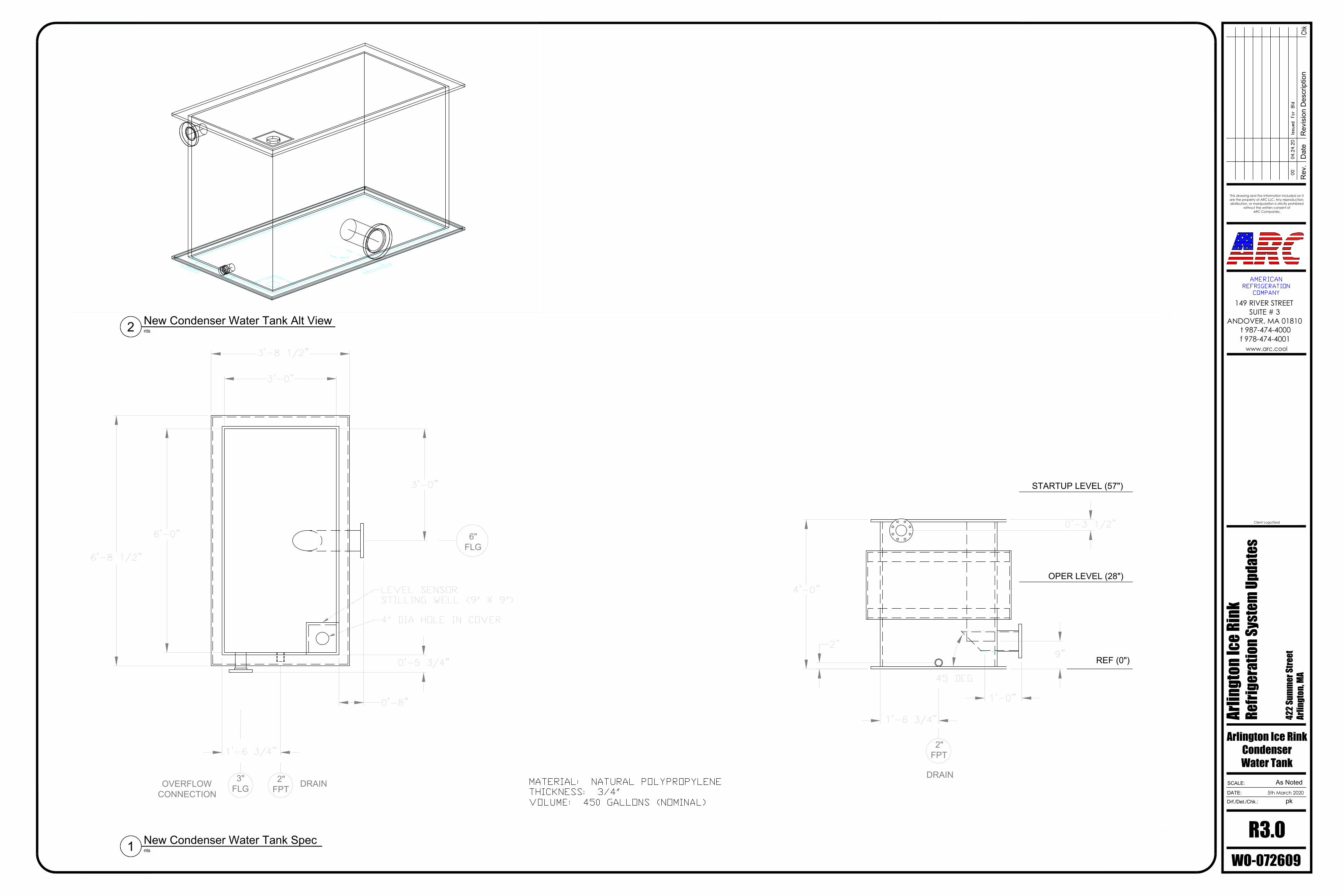
2"FPT DRAIN3"
FLGOVERFLOWCONNECTION
REF (0")
OPER LEVEL (28")
6"FLG
STARTUP LEVEL (57")
2"FPT
DRAIN
Rev
.
Drf./Det./Chk.:
SCALE:
DATE:
Dat
eR
evis
ion
Des
crip
tion
Arlin
gton
Ice R
ink
Refri
gera
tion S
yste
m U
pdat
es
422 S
umm
er St
reet
Arlin
gton
, MA
WO-072609
5th March 2020
Chk
This drawing and the information included on itare the property of ARC LLC. Any reproduction,distribution, or manipulation is strictly prohibted
without the written consent ofARC Companies.
www.arc.cool
149 RIVER STREETSUITE # 3
ANDOVER, MA 01810 t 987-474-4000f 978-474-4001
Client Logo/Seal
R3.0pk
As Noted
Arlington Ice RinkCondenserWater Tank
New Condenser Water Tank Specnts1
New Condenser Water Tank Alt Viewnts2
AutoCAD SHX Text
MATERIAL: NATURAL POLYPROPYLENE THICKNESS: 3/4" VOLUME: 450 GALLONS (NOMINAL)
AutoCAD SHX Text
4" DIA HOLE IN COVER
AutoCAD SHX Text
LEVEL SENSOR STILLING WELL (9" X 9")
AutoCAD SHX Text
PK
AutoCAD SHX Text
AMERICAN REFRIGERATION COMPANY
AutoCAD SHX Text
00
AutoCAD SHX Text
04.24.20
AutoCAD SHX Text
Issued For Bid