ECS K8M800-M2 Manual -...
67
-
Upload
nguyenphuc -
Category
Documents
-
view
215 -
download
0
Transcript of ECS K8M800-M2 Manual -...


Preface
i
PrefaceCopyright
This publication, including all photographs, illustrations and software, is protected underinternational copyright laws, with all rights reserved. Neither this manual, nor any of thematerial contained herein, may be reproduced without written consent of the author.
Version 1.0
DisclaimerThe information in this document is subject to change without notice. The manufacturermakes no representations or warranties with respect to the contents hereof and specificallydisclaims any implied warranties of merchantability or fitness for any particular purpose.The manufacturer reserves the right to revise this publication and to make changes fromtime to time in the content hereof without obligation of the manufacturer to notify anyperson of such revision or changes.
Trademark RecognitionMicrosoft, MS-DOS and Windows are registered trademarks of Microsoft Corp.
AMD, Athlon, Sempron, and Duron are registered trademarks of AMD Corporation.
Other product names used in this manual are the properties of their respective owners andare acknowledged.
Federal Communications Commission (FCC)This equipment has been tested and found to comply with the limits for a Class B digitaldevice, pursuant to Part 15 of the FCC Rules. These limits are designed to provide reason-able protection against harmful interference in a residential installation. This equipmentgenerates, uses, and can radiate radio frequency energy and, if not installed and used inaccordance with the instructions, may cause harmful interference to radio communications.However, there is no guarantee that interference will not occur in a particular installation.If this equipment does cause harmful interference to radio or television reception, whichcan be determined by turning the equipment off and on, the user is encouraged to try tocorrect the interference by one or more of the following measures:
• Reorient or relocate the receiving antenna.• Increase the separation between the equipment and the receiver.• Connect the equipment onto an outlet on a circuit different from that to which
the receiver is connected.• Consult the dealer or an experienced radio/TV technician for help.
Shielded interconnect cables and a shielded AC power cable must be employed with thisequipment to ensure compliance with the pertinent RF emission limits governing thisdevice. Changes or modifications not expressly approved by the system’s manufacturercould void the user’s authority to operate the equipment.

ii
Preface
Declaration of ConformityThis device complies with part 15 of the FCC rules. Operation is subject to the followingconditions:
• This device may not cause harmful interference, and• This device must accept any interference received, including interference
that may cause undesired operation.
Canadian Department of CommunicationsThis class B digital apparatus meets all requirements of the Canadian Interference-causingEquipment Regulations.
Cet appareil numérique de la classe B respecte toutes les exigences du Réglement sur lematériel brouilieur du Canada.
About the ManualThe manual consists of the following:
Chapter 1
Introducing the Motherboard
Chapter 2
Installing the Motherboard
Chapter 3
Using BIOS
Chapter 4
Using the Motherboard Software
Describes features of the motherboard.
Go to page 1
Describes installation of motherboardcomponents.
Go to page 7
Provides information on using the BIOSSetup Utility.
Go to page 25
Describes the motherboard software
Go to page 45
Provides information about SATA RAIDSetup
Go to page 49
Chapter 5
VIA VT8237 SATA RAID Setup Guide

iii
TTTTTABLE OF CONTENTSABLE OF CONTENTSABLE OF CONTENTSABLE OF CONTENTSABLE OF CONTENTS
Preface i
Chapter 1 1Introducing the Motherboard 1
Introduction................................................................................................1Features.......................................................................................................2 Motherboard Components.......................................................................4
Chapter 2 7 7 7 7 7Installing the Motherboard 7
Safety Precautions......................................................................................7Choosing a Computer Case.......................................................................7Installing the Motherboard in a Case......................................................7Checking Jumper Settings.........................................................................8
Setting Jumpers..............................................................................8Checking Jumper Settings..............................................................9Jumper Settings..............................................................................9
Connecting Case Components...............................................................10Front Panel Connector.................................................................12
Installing Hardware...................................................................................13Installing the Processor...............................................................13Installing Memory Modules.........................................................14Installing a Hard Disk Drive/CD-ROM/SATA Hard Drive........18Installing a Floppy Diskette Drive...............................................20Installing Add-on Cards..............................................................20Connecting Optional Devices......................................................22
Connecting I/O Devices..........................................................................24
Chapter 3 25 25 25 25 25Using BIOS 25
About the Setup Utility............................................................................25The Standard Configuration........................................................25Entering the Setup Utility..............................................................25Updating the BIOS.......................................................................27
Using BIOS................................................................................................27Standard CMOS Features...........................................................28Advanced BIOS Features.............................................................30Advanced Chipset Features.........................................................32

iv
Integrated Peripherals.................................................................35Power Management Setup...........................................................38PNP/PCI Configurations.............................................................40PC Health Status..........................................................................41Frequency/Voltage Control..........................................................42Load Fail-Safe Defaults................................................................43Load Optimized Defaults.............................................................43Set Supervisor/User Password....................................................43Save & Exit Setup Option.............................................................44Exit Without Saving......................................................................44
Chapter 4 45 45 45 45 45Using the Motherboard Software 45
About the Software CD-ROM................................................................45Auto-installing under Windows 98/ME/2000/XP................................45
Running Setup..............................................................................46Manual Installation..................................................................................48Utility Software Reference.......................................................................48
Chapter 5 49 49 49 49 49VIA VT8237 SATA RAID Setup Guide 49
VIA RAID Configurations.......................................................................49Installing RAID Software & Drives.......................................................56
Multi-Language Translation
Using VIA RAID Tool.............................................................................58
1
Introducing the Motherboard
Chapter 1Introducing the Motherboard
IntroductionThank you for choosing K8M800-M2 motherboard of great performance and with en-hanced function. The K8M800-M2 is designed to fit the AMD K8 processors in the 754-pin package. Two 184 pin unbuffered DDR SDRAM DIMM sockets support up to 2 GB intotal memory. Based on the uATX form factor, this motherboard incorporates the follow-ing chipsets: K8M800 chipset family Northbridge and VT8237 Southbridge chipsets.
The K8M800 Northbridge features the Hyper Transport Technology to transfer of 1600MT/s, 1200 MT/s, 800 MT/s or 400 MT/s each direction simultaneously, providing a totalmaximum data transfer bandwidth of 6.4GB/sec. The AGP controller is AGP v3.0 compliant8X/4X transfer mode with up to 2.1 GB/sec data transfer rate. The K8M800 Northbridgeinterconnects to the South Bridge through the high speed 8X 66 MHz (533 MB/sec) V-Linkinterface.
The VT8237 Southbridge is a highly integrated peripheral controller, it includes an inte-grated keyboard controller with PS2 mouse support, two-channel Serial ATA/RAID harddisk controller, master mode enhanced Parallel IDE controller with full scatter/gathercapability and extension to UltraDMA-133/100/66 for 133/100/66 MB/sec transfer rate,integrated USB 2.0 interface and OnNow/ACPI compliant advanced configuration andpower management interface. The VT8237 features outstanding expansion capibility suchas, three PCI slots with PCI v2.2 compliant and one optional CNR slot. The VT8237integrated Fast Ethernet controller with standard MII interface to an external PHY for 10/100Mb Base-T Ethernet.
There is an advanced full set of I/O ports in the rear panel, including PS/2 mouse andkeyboard connectors, COM1, LPT1, four USB ports at the rear I/O and 2 headers onboard, one LAN port (optional), and audio jacks for microphone, line-in, and line-out. Thismotherboard is designed in an uATX form factor using a four-layer printed circuit board andmeasures 244 mm x 244 mm.

2
Introducing the Motherboard
Feature
ProcessorK8M800-M2 uses a 754-pin socket that carries the following features:
• Supports AMD K8 processors with HyperTransport Technology
The VIA K8M800 Northbridge (NB) and VIA VT8237 Southbridge (SB) chipset is basedon an innovative and scalable architecture with proven reliability and performance.
K8M800 (NB) • 800/600/400/200 MHz clock rates with “Double Data Rate”-style operation for 1600/1200/800/400 MT/s in both direc-tions simultaneously
• Supports 66 MHz, 8X/4X transfer modes, V-Link Host inter-face with total bandwidth of 533 MB/sec
• AGP v3.0 compliant with 8X/4X transfer mode with FastWrite support
VT8237 (SB)
Memory• Supports DDR400/333/266/200 memory types• Accommodates two unbuffered 2.5V 184-pin DDR SDRAM DIMM sockets• A total maximum capacity 2 GB
AC’97 Audio CODECThe AC’97 Audio CODEC is compliant with the AC’97 2.3 specification that provides8bit/16bit mono/stereo PCM data format support. Features include support for 32-byteline-buffers for each SGD channel and digital S/PDIF IN/OUT.
• Supports 16-bit 66 MHz V-Link Host interface with totalbandwidth of 1066 MB/s
• Compliant with PCI 2.2 specification at 33 MHz, supportingup to 6 PCI masters
• Integrated Dual channel UltraDMA 133/100/66 Master ModeEIDE Controller
• USB 2.0 Controller, supporting for 8 USB 2.0/1.1 ports• Integrated keyboard Controller with PS2 mouse support
Chipset
HyperTransport Technology is a point-to-point link between two devices, it enablesintegrated circuits to exchange information at much higher speeds than currently avail-able interconnect technologies.

3
Introducing the Motherboard
This motherboard supports Ultra DMA bus mastering with transfer rates of 133/100/66MB/s.
The motherboard comes with the following expansion options:• Three 32-bit PCI slots• One AGP slot• Two IDE connectors which support four IDE devices• One floppy disk drive interface• A Communications Networking Riser (CNR) slot• Two 7-pin SATA connectors
Expansion Options
BIOS FirmwareThe motherboard uses Award BIOS that enables users to configure many system featuresincluding the following:
• Power management• Wake-up alarms• CPU parameters• CPU and memory timing
The firmware can also be used to set parameters for different processor clock speeds.
Onboard LAN (optional)
• Supports 10Mb/s and 100Mb/s N-Way Auto-negotiation operation• Half and Full Duplex• Supports Wake-on-LAN (WOL) function and remote wake-up
The onboard LAN provides the following features:
Some hardware specifications and software items are subject to changewithout prior notice.
Integrated I/OThe motherboard has a full set of I/O ports and connectors:
• Two PS/2 ports for mouse and keyboard• One serial port• One parallel port• Eight USB ports (rear panel x 4, header x 4)• One LAN port (optional)• One VGA port• Audio jacks for microphone, line-in and line-out
4
Introducing the Motherboard
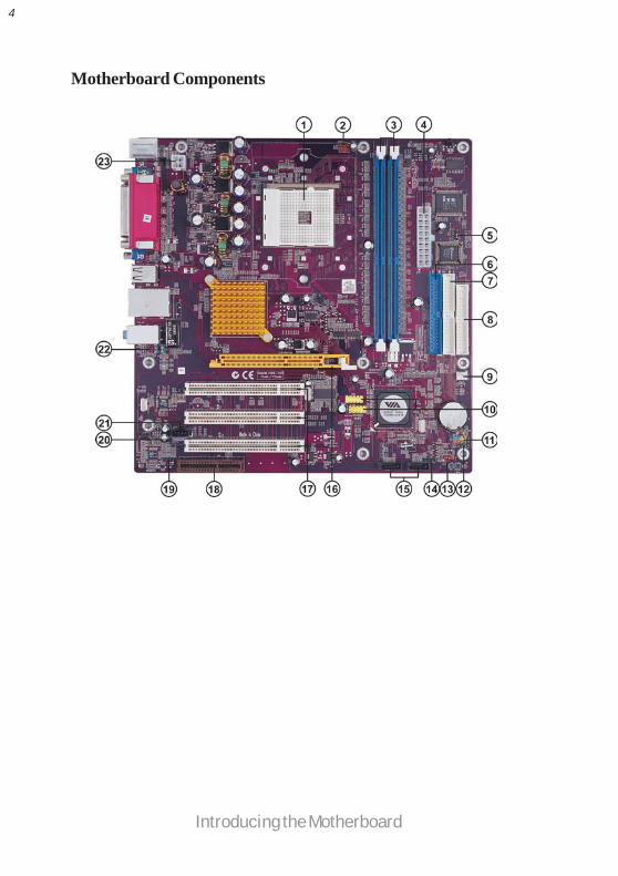
Motherboard Components
5
Introducing the Motherboard
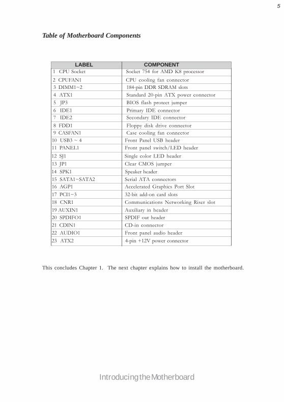
Table of Motherboard Components
7 IDE2 Secondary IDE connector
16 AGP1 Accelerated Graphics Port Slot
13 JP1 Clear CMOS jumper
11 PANEL1 Front panel switch/LED header
22 AUDIO1 Front panel audio header
4 ATX1 Standard 20-pin ATX power connector
LABEL COMPONENT1 CPU Socket Socket 754 for AMD K8 processor
6 IDE1 Primary IDE connector
15 SATA1~SATA2 Serial ATA connectors
9 CASFAN1 Case cooling fan connector8 FDD1 Floppy disk drive connector
18 CNR1 Communications Networking Riser slot17 PCI1~3 32-bit add-on card slots
20 SPDIFO1 SPDIF out header19 AUXIN1 Auxiliary in header
2 CPUFAN1 CPU cooling fan connector
23 ATX2 4-pin +12V power connector
3 DIMM1~2 184-pin DDR SDRAM slots
5 JP3 BIOS flash protect jumper
21 CDIN1 CD-in connector
This concludes Chapter 1. The next chapter explains how to install the motherboard.
10 USB3 ~ 4 Front Panel USB header
12 SJ1 Single color LED header
14 SPK1 Speaker header

6
Introducing the Motherboard
Memo
7
Installing the Motherboard
Chapter 2Installing the Motherboard
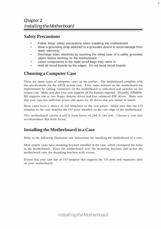
Safety Precautions• Follow these safety precautions when installing the motherboard• Wear a grounding strap attached to a grounded device to avoid damage from
static electricity• Discharge static electricity by touching the metal case of a safely grounded
object before working on the motherboard• Leave components in the static-proof bags they came in• Hold all circuit boards by the edges. Do not bend circuit boards
Choosing a Computer Case
There are many types of computer cases on the market. The motherboard complies withthe specifications for the uATX system case. First, some features on the motherboard areimplemented by cabling connectors on the motherboard to indicators and switches on thesystem case. Make sure that your case supports all the features required. Secondly, K8M800-M2 supports one or two floppy diskette drives and four enhanced IDE drives. Make surethat your case has sufficient power and space for all drives that you intend to install.
Most cases have a choice of I/O templates in the rear panel. Make sure that the I/Otemplate in the case matches the I/O ports installed on the rear edge of the motherboard.
This motherboard carries a uATX form factor of 244 X 244 mm. Choose a case thataccommodates this form factor.
Installing the Motherboard in a Case
Refer to the following illustration and instructions for installing the motherboard in a case.
Most system cases have mounting brackets installed in the case, which correspond the holesin the motherboard. Place the motherboard over the mounting brackets and secure themotherboard onto the mounting brackets with screws.
Ensure that your case has an I/O template that supports the I/O ports and expansion slotson your motherboard.

8
Installing the Motherboard
Checking Jumper SettingsThis section explains how to set jumpers for correct configuration of the motherboard.
Setting JumpersUse the motherboard jumpers to set system configuration options. Jumpers with more thanone pin are numbered. When setting the jumpers, ensure that the jumper caps are placed onthe correct pins.
The illustrations show a 2-pin jumper. Whenthe jumper cap is placed on both pins, thejumper is SHORT. If you remove the jumpercap, or place the jumper cap on just one pin,the jumper is OPEN.
This illustration shows a 3-pin jumper. Pins1 and 2 are SHORT
SHORT OPEN
Do not over-tighten the screws as this can stress the motherboard.

9
Installing the Motherboard
Jumper Settings
Checking Jumper SettingsThe following illustration shows the location of the motherboard jumpers. Pin 1 is labeled.
Jumper Type Description Setting (default)
JP1 3-pin CLEAR CMOS 1-2: NORMAL2-3: CLEAR
Before clearing the CMOS,make sure to turn the sys-tem off.
3-pinJP3 BIOS PROTECT 1-2: DISABLE2-3: ENABLE

10
Installing the Motherboard
Connecting Case ComponentsAfter you have installed the motherboard into a case, you can begin con-necting the motherboard components. Refer to the following:
1 Connect the CPU cooling fan cable to CPUFAN1.2 Connect the case cooling fan connector to CASFAN1.3 Connect the case speaker cable to SPK1.4 Connect the case switches and indicator LEDs to the PANEL1. If there are 3
pins in the case LED cable, connect to SJ1.5 Connect the standard power supply connector to ATX1.6 Connect the auxiliary case power supply connector to ATX2.
CPUFAN1/CASEFAN1: FAN Power Connectors
SPK1: Internal speakerPin Signal Name1 VCC
2 NC
4 Signal
3 Ground
1 GND System Ground
2 +12V Power +12V
3 Sense Sensor
Pin Signal Name Function

11
Installing the Motherboard
SJ1: Single-color LED header
Pin Signal Name1 ACPI LED
2 ACPI LED
Pin Signal Name
ATX1: ATX 20-pin Power Connector
ACPI LED function
3 5VSB
Light Blinking Blinking Dark
S0 S1 S3 S4/S5
1 +3.3V 11 +3.3V
2 +3.3V 12 -12V
10 +12V 20 +5V
3 Ground 13 Ground
4 +5V 14 PS ON#
5 Ground 15 Ground
6 +5V 16 Ground
7 Ground 17 Ground
8 PWRGD 18 -5V
9 +5VSB 19 +5V
Pin Signal Name Pin Signal Name
ATX2: ATX 12V Power Connector
Pin Signal Name
4 +12V
3 +12V
2 Ground
1 Ground

12
Installing the Motherboard
Front Panel HeaderThe front panel connector (PANEL1) provides a standard set of switch and LED headercommonly found on ATX or micro-ATX cases. Refer to the table below for information:
Pin Signal Name Function
1 HD_LED_P Hard disk LED(+) 2 FP PWR/SLP *MSG LED(+)
3 HD_LED_N Hard disk LED(-)
5 RST_SW_N Reset Switch(-)
7 RST_SW_P Reset Switch(+)
9 RSVD Reserved
4 FP PWR/SLP *MSG LED(-)
6 PWR_SW_P Power Switch(+)
8 PWR_SW_N Power Switch(-)
10 Key No pin
* MSG LED (dual color or single color)
Pin Signal Name Function
Hard Drive Activity LED
Connecting pins 1 and 3 to a front panel mounted LED provides visual indication that datais being read from or written to the hard drive. For the LED to function properly, an IDEdrive should be connected to the onboard IDE interface. The LED will also show activityfor devices connected to the SCSI (hard drive activity LED) connector.
Power/Sleep/Message waiting LED
Connecting pins 2 and 4 to a single or dual-color, front panel mounted LED provides poweron/off, sleep, and message waiting indication.
Reset Switch
Supporting the reset function requires connecting pin 5 and 7 to a momentary-contactswitch that is normally open. When the switch is closed, the board resets and runs POST.
Power Switch
Supporting the power on/off function requires connecting pins 6 and 8 to a momentary-contact switch that is normally open. The switch should maintain contact for at least 50 msto signal the power supply to switch on or off. The time requirement is due to internal de-bounce circuitry. After receiving a power on/off signal, at least two seconds elapses beforethe power supply recognizes another on/off signal.
13
Installing the Motherboard
Installing HardwareInstalling the Processor
Caution: When installing a CPU heatsink and cooling fan make sure thatyou DO NOT scratch the motherboard or any of the surface-mountresistors with the clip of the cooling fan. If the clip of the cooling fanscrapes across the motherboard, you may cause serious damage to themotherboard or its components.
On most motherboards, there are small surface-mount resistors near theprocessor socket, which may be damaged if the cooling fan is carelesslyinstalled.
Avoid using cooling fans with sharp edges on the fan casing and the clips.Also, install the cooling fan in a well-lit work area so that you can clearlysee the motherboard and processor socket.
Before installing the Processor
This motherboard automatically determines the CPU clock frequency and system busfrequency for the processor. You may be able to change these settings by changing thesettings in the system Setup Utility. We strongly recommend that you do not over-clockprocessors or other components to run faster than their rated speed.
Warning: Over-clocking components can adversely affect the reliability ofthe system and introduce errors into your system. Over-clocking canpermanently damage the motherboard by generating excess heat incomponents that are run beyond the rated limits.
This motherboard has a Socket 754 processor socket. When choosing a processor, considerthe performance requirements of the system. Performance is based on the processor design,the clock speed and system bus frequency of the processor, and the quantity of internalcache memory and external cache memory.

14
Installing the Motherboard
1 Install your CPU. Pull up the lever away from thesocket and lift up to 90-degree angle.
2 Locate the CPU cut edge (the corner with the pinhold noticeably missing). Align and insert the CPUcorrectly.
3 Press the lever down and apply thermal grease ontop of the CPU.
4 Put the CPU Fan down on the retention module andsnap the four retention legs of the cooling fan intoplace.
5 Flip the levers over to lock the heat sink in place andconnect the CPU cooling Fan power cable to theCPUFAN connector. This completes the installa-tion.
CPU Installation ProcedureThe following illustration shows CPU installation components.
Installing Memory ModulesK8M800-M2 accommodates two 184-pin 2.5V unbuffered Double Data Rate (DDR) SDRAM(Synchronous Dynamic Random Access Memory) memory modules. K8M800-M2 cansupport DDR400/DDR333/DDR266/DDR200 memory types and its total maximum memorysize is 2 GB.
Do not remove any memory module from its antistatic packaging until youare ready to install it on the motherboard. Handle the modules only bytheir edges. Do not touch the components or metal parts. Always wear agrounding strap when you handle the modules.
DDR SDRAM memory module table
Memory module Memory Bus
DDR266 133MHzDDR333 166MHzDDR400 200MHz
DDR200 100MHz
To achieve better airflow rates and heat dissipation, we suggest that you usea high quality fan with 4800 rpm at least. CPU fan and heatsink installa-tion procedures may vary with the type of CPU fan/heatsink supplied. Theform and size of fan/heatsink may also vary.

15
Installing the Motherboard
Installation ProcedureRefer to the following to install the memory modules.
1 This motherboard supports unbuffered DDR SDRAM only.2 Push the latches on each side of the DIMM slot down.3 Align the memory module with the slot. The DIMM slots are keyed with
notches and the DIMMs are keyed with cutouts so that they can only beinstalled correctly.
4 Check that the cutouts on the DIMM module edge connector match the notchesin the DIMM slot.
5 Install the DIMM module into the slot and press it firmly down until it seatscorrectly. The slot latches are levered upwards and latch on to the edges ofthe DIMM.
6 Install any remaining DIMM modules.

16
Installing the Motherboard
1 DIMM 1 connects to command/address pins MEMADDA [13:0], MEMBANKA [1:0], MEMRASA_L,MEMCASA_L, MEMWEA_L, MEMCKEA.
2 DIMM 2 connects to command/address pins MEMADDB [13:0], MEMBANKB [1:0], MEMRASB_L,MEMCASB_L, MEMWEB_L, MEMCKEB.
3 2T timing is supported in CG and later silicon revisions. Refer to the AMD Athlon™ 64 ProcessorPower and Thermal Data Sheet, order #30430, for silicon revision determination.
4 The maximum allowable DRAM speed under these high load conditions may be reduced with certainDIMMs due to signal integrity degradation.
Table A: Unbuffered DIMM Support for 754-pin
Numbers ofDIMMs5
Maximum DRAMSpeed
1 T 2 T3
DDR400 DDR400
DDR400 DDR400
DDR400 DDR400
DDR400 DDR400
DDR400 DDR400
DDR400 DDR400
DDR400 DDR400
DDR333 DDR333
DIMM 14.1.5 DIMM 22
single rank
empty
empty
single rank
empty
double rank empty
double ranksingle ranksingle rank
single rank double rank
double rankdouble rank
single rank
double rank
11112222

17
Installing the Motherboard
Table B: DDR (memory module) QVL (Qualified Vendor List)The following DDR400 memory modules have been tested and qualified for use with thismotherboard.
Size Vendor Module Name
NANYA NT128D64SH4B1G-5 Infineon HYS64D16301GU-5-B
128MB
NANYA NT128D64SH4B1G-5T Micron MT16VDDT3264AG-403B2
NANYA NT256D64S88B1G-5 Infineon HYS64D32300GU-5-B NANYA NT256D64S88B1G-5T Infineon HYS64D32300HU-5-C
SAMSUNG M368L3223DTM-CC4
256MB
Micron MT8VDDT3264AG-40BC4 SAMSUNG M368L6423DTM-CC4
NANYA NT512D64S8HB1G-5T Infineon HYS64D64320HU-5-C Micron MT16VDDT6464AG-40BC4
512MB
SAMSUNG M368L6423ETM-CC4

18
Installing the Motherboard
IDE devices enclose jumpers or switches used to set the IDE device as MASTER or SLAVE.Refer to the IDE device user’s manual. Installing two IDE devices on one cable, ensure thatone device is set to MASTER and the other device is set to SLAVE. The documentation ofyour IDE device explains how to do this.
About UltraDMAThis motherboard supports UltraDMA 133/100/66. UDMA is a technology that acceler-ates the performance of devices in the IDE channel. To maximize performance, install IDEdevices that support UDMA and use 80-pin IDE cables that support UDMA 133/100/66.
Installing a Hard Disk Drive/CD-ROM/SATA Hard DriveThis section describes how to install IDE devices such as a hard disk drive and a CD-ROMdrive.
About IDE DevicesYour motherboard has a primary and secondary IDE channel interface (IDE1 and IDE2).An IDE ribbon cable supporting two IDE devices is bundled with the motherboard.
You must orient the cable connector so that the pin1 (color) edge of thecable correspoinds to the pin 1 of the I/O port connector.
IDE1: Primary IDE ConnectorThe first hard drive should always be connected to IDE1.
IDE2: Secondary IDE ConnectorThe second drive on this controller must be set to slave mode. The cinfiguration is the sameas IDE1.

19
Installing the Motherboard
About SATA ConnectorsYour motherboard features two SATA connectors supporting a total of two drives. SATArefers to Serial ATA (Advanced Technology Attachment) is the standard interface for theIDE hard drives which are currently used in most PCs. These connectors are well designedand will only fit in one orientation. Locate the SATA connectors on the motherboard (seepage 21) and follow the illustration below to install the SATA hard drives.
Installing Serial ATA Hard DrivesTo install the Serial ATA (SATA) hard drives, use the SATA cable that supports the SerialATA protocol. This SATA cable comes with an SATA power cable. You can connect eitherend of the SATA cable to the SATA hard drive or the connector on the motherboard.
SATA cable (optional) SATA power cable (optional)
Refer to the illustration below for proper installation:
This motherboard does not support the “Hot-Plug” function.
1 Attach either cable end to the connector on the motherboard.2 Attach the other cable end to the SATA hard drive.3 Attach the SATA power cable to the SATA hard drive and connect the other
end to the power supply.

20
Installing the Motherboard
Installing Add-on CardsThe slots on this motherboard are designed to hold expansion cards and connect them to thesystem bus. Expansion slots are a means of adding or enhancing the motherboard’s featuresand capabilities. With these efficient facilities, you can increase the motherboard’s capabili-ties by adding hardware that performs tasks that are not part of the basic system.
FDD1: Floppy Disk ConnectorThis connector supports the provided floppydrive ribbon cable. After connecting the singleend to the onboard floppy connector, connectthe remaining plugs on the other end to thefloppy drives correspondingly.
Installing a Floppy Diskette DriveThe motherboard has a floppy diskette drive (FDD) interface and ships with a diskette driveribbon cable that supports one or two floppy diskette drives. You can install a 5.25-inchdrive and a 3.5-inch drive with various capacities. The floppy diskette drive cable has onetype of connector for a 5.25-inch drive and another type of connector for a 3.5-inch drive.
You must orient the cable connector so that the pin 1 (color) edge of thecable corresponds to the pin 1 of the I/O port connector.

21
Installing the Motherboard
Before installing an add-on card, check the documentation for the cardcarefully. If the card is not Plug and Play, you may have to manuallyconfigure the card before installation.
AGP Slot
PCI Slot K8M800-M2 is equipped with three standard PCI slots. PCI stands forPeripheral Component Interconnect and is a bus standard for expansioncards, which for the most part, is a supplement of the older ISA bus stan-dard. The PCI slots on this board are PCI v2.2 compliant.
The AGP slot is used to install a graphics adapter that supports the 8X/4XAGP specification. It is AGP 3.0 compliant.
CNR Slot This slot is used to insert CNR cards with Modem and Audio functionality.
For some add-on cards, for example graphics adapters and network adapt-ers, you have to install drivers and software before you can begin using theadd-on card.
Follow these instructions to install an add-on card:
1 Remove a blanking plate from the system case corresponding to the slot youare going to use.
2 Install the edge connector of the add-on card into the expansion slot. Ensurethat the edge connector is correctly seated in the slot.
3 Secure the metal bracket of the card to the system case with a screw.
22
Installing the Motherboard
Pin Signal Name
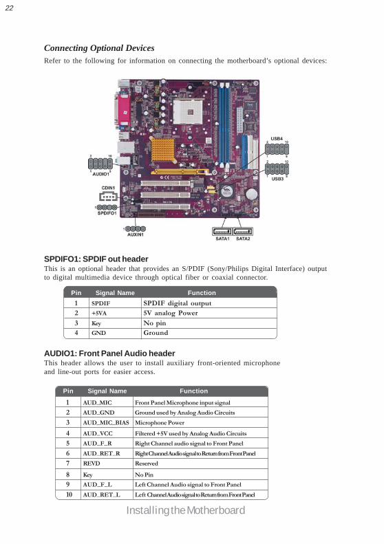
AUDIO1: Front Panel Audio headerThis header allows the user to install auxiliary front-oriented microphoneand line-out ports for easier access.
Pin Signal Name Function
1 AUD_MIC Front Panel Microphone input signal
2 AUD_GND Ground used by Analog Audio Circuits
3 AUD_MIC_BIAS Microphone Power
4 AUD_VCC Filtered +5V used by Analog Audio Circuits
5 AUD_F_R Right Channel audio signal to Front Panel
6 AUD_RET_R Right Channel Audio signal to Return from Front Panel
7 REVD Reserved
8 Key No Pin
9 AUD_F_L Left Channel Audio signal to Front Panel
10 AUD_RET_L Left Channel Audio signal to Return from Front Panel
SPDIFO1: SPDIF out headerThis is an optional header that provides an S/PDIF (Sony/Philips Digital Interface) outputto digital multimedia device through optical fiber or coaxial connector.
Pin Signal Name Function1 SPDIF SPDIF digital output2 +5VA 5V analog Power
3 Key No pin4 GND Ground
Connecting Optional DevicesRefer to the following for information on connecting the motherboard’s optional devices:

23
Installing the Motherboard
AUXIN1: Auxiliary In headerThis connector is an additional line-in audio connector. It allows you to attach a line-incable when your rear line-in jack is set as line out port for 4-channel function.
USB3/USB4: Front Panel USB headerThe motherboard has four USB ports installed on the rear edge I/O port array. Additionally,some computer cases have USB ports at the front of the case. If you have this kind of case,use auxiliary USB connector to connect the front-mounted ports to the motherboard.
CDIN1: CD Audio Input header
Pin Signal Name Function1 CD in_L CD In left channel2 GND Ground3 GND Ground
4 CD in_R CD In right channel
Pin Signal Name Function1 AUX_L AXU In left channel2 GND Ground
3 GND Ground4 AUX_R AXU In right channel
Please make sure that the USB cable has the same pin assignment as indi-cated above. A different pin assignment may cause damage or system hang-up.
1 USBPWR Front Panel USB Power
2 USBPWR Front Panel USB Power
3 USB_FP_P0- USB Port 0 Negative Signal
4 USB_FP_P1- USB Port 1 Negative Signal
5 USB_FP_P0+ USB Port 0 Positive Signal
6 USB_FP_P1+ USB Port 1 Positive Signal
7 GND Ground
8 GND Ground
9 Key No pin
10 USB_FP_OC0 Overcurrent signal
Pin Signal Name Function

24
Installing the Motherboard
Connecting I/O DevicesThe backplane of the motherboard has the following I/O ports:
PS2 Mouse Use the upper PS/2 port to connect a PS/2 pointing device.
PS2 Keyboard Use the lower PS/2 port to connect a PS/2 keyboard.
Parallel Port (LPT1) Use LPT1 to connect printers or other parallel communications devices.
Serial Port Use the COM port to connect serial devices such as mice or(COM1) fax/modems.
LAN Port (optional)
VGA Port Connect your monitor to the VGA port.
USB Ports Use the USB ports to connect USB devices.
Audio Ports
This concludes Chapter 2. The next chapter covers the BIOS.
Use the three audio ports to connect audio devices. The first jackis for stereo line-in signal. The second jack is for stereo line-outsignal. The third jack is for microphone.
Connect an RJ-45 jack to the LAN port to connect your computerto the Network.

25
Using BIOS
Chapter 3
Using BIOS
About the Setup UtilityThe computer uses the latest Award BIOS with support for Windows Plug and Play. TheCMOS chip on the motherboard contains the ROM setup instructions for configuring themotherboard BIOS.
The BIOS (Basic Input and Output System) Setup Utility displays the system’s configura-tion status and provides you with options to set system parameters. The parameters arestored in battery-backed-up CMOS RAM that saves this information when the power isturned off. When the system is turned back on, the system is configured with the values youstored in CMOS.
The BIOS Setup Utility enables you to configure:• Hard drives, diskette drives and peripherals• Video display type and display options• Password protection from unauthorized use• Power Management features
The settings made in the Setup Utility affect how the computer performs. Before using theSetup Utility, ensure that you understand the Setup Utility options.
This chapter provides explanations for Setup Utility options.
The Standard ConfigurationA standard configuration has already been set in the Setup Utility. However, we recommendthat you read this chapter in case you need to make any changes in the future.
This Setup Utility should be used:• when changing the system configuration• when a configuration error is detected and you are prompted to make changes
to the Setup Utility• when trying to resolve IRQ conflicts• when making changes to the Power Management configuration• when changing the password or making other changes to the Security Setup
Entering the Setup UtilityWhen you power on the system, BIOS enters the Power-On Self Test (POST) routines.POST is a series of built-in diagnostics performed by the BIOS. After the POST routines arecompleted, the following message appears:

26
Using BIOS
Press DEL to enter SETUPPressing the delete key accesses the BIOS Setup Utility:
Advanced Chipset Features Load Optimized Defaults
PC Health Status Exit Without Saving
Phoenix-AwardBIOS CMOS Setup Utility:
Standard CMOS Features Frequency/Voltage Control
Esc: Quit : Select ItemF10: Save & Exit Setup
Time, Date, Hard Disk Type...
Advanced BIOS Features Load Fail-Safe Defaults
Integrated Peripherals Set Supervisor Password
Power Management Setup Set User Password PnP/PCI Configurations Save & Exit Setup
KEY FUNCTIONESC Exits the current menu
Scrolls through the items on a menu+/-/PU/PD Modifies the selected field’s values
F10 Saves the current configuration and exits setupF1 Displays a screen that describes all key functionsF5 Loads previously saved values to CMOSF6 Loads a minimum configuration for troubleshootingF7 Loads an optimum set of values for peak performance
BIOS Navigation KeysThe BIOS navigation keys are listed below:

27
Using BIOS
Updating the BIOSYou can download and install updated BIOS for this motherboard from the manufacturer’sWeb site. New BIOS provides support for new peripherals, improvements in performance,or fixes for known bugs. Install new BIOS as follows:
1 If your motherboard has a BIOS protection jumper, change the setting to allowBIOS flashing.
2 If your motherboard has an item called Firmware Write Protect in AdvancedBIOS features, disable it. (Firmware Write Protect prevents BIOS from beingoverwritten.
3 Create a bootable system disk. (Refer to Windows online help for informationon creating a bootable system disk.)
4 Download the Flash Utility and new BIOS file from the manufacturer’s Website. Copy these files to the system diskette you created in Step 3.
5 Turn off your computer and insert the system diskette in your computer’s diskette drive. (You might need to run the Setup Utility and changethe boot priority items on the Advanced BIOS Features Setup page, to forceyour computer to boot from the floppy diskette drive first.)
6 At the A:\ prompt, type the Flash Utility program name and press <Enter>.7 Type the filename of the new BIOS in the “File Name to Program” text box.
Follow the onscreen directions to update the motherboard BIOS.8 When the installation is complete, remove the floppy diskette from the diskette
drive and restart your computer. If your motherboard has a Flash BIOS jumper,reset the jumper to protect the newly installed BIOS from being overwritten.
Using BIOSWhen you start the Setup Utility, the main menu appears. The main menu of the SetupUtility displays a list of the options that are available. A highlight indicates which option iscurrently selected. Use the cursor arrow keys to move the highlight to other options. Whenan option is highlighted, execute the option by pressing <Enter>.
Some options lead to pop-up dialog boxes that prompt you to verify that you wish toexecute that option. Other options lead to dialog boxes that prompt you for information.
Some options (marked with a triangle ) lead to submenus that enable you to change thevalues for the option. Use the cursor arrow keys to scroll through the items in the submenu.
In this manual, default values are enclosed in parenthesis. Submenu items are denoted by atriangle .

28
Using BIOS
Standard CMOS FeaturesThis option displays basic information about your system.
Date and TimeThe Date and Time items show the current date and time on the computer. Ifyou are running a Windows OS, these items are automatically updated whenever you makechanges to the Windows Date and Time Properties utility.
IDE Devices (None)Your computer has two IDE channels (Primary and Secondary) and each channel can beinstalled with one or two devices (Master and Slave). Use these items toconfigure each device on the IDE channel.
IDE HDD Auto-DetectionPress <Enter> while this item is highlighted to prompt the Setup Utility to automaticallydetect and configure an IDE device on the IDE channel.
If you are setting up a new hard disk drive that supports LBA mode, morethan one line will appear in the parameter box. Choose the line that listsLBA for an LBA drive.
Phoenix-AwardBIOS CMOS Setup UtilityStandard CMOS Features
Date (mm:dd:yy) Wed, Feb 25 2004Time (hh:mm:ss) 9 : 33 : 26
IDE Channel 0 MasterIDE Channel 0 SlaveIDE Channel 1 MasterIDE Channel 1 SlaveIDE Channel 2 MasterIDE Channel 3 MasterDrive A [1.44M, 3.5 in.]Drive B [None]Video [EGA/VGA]Halt On [All Errors]
Base Memory 640KExtended Memory 65535KTotal Memory 1024K
Item Help
Menu LevelChange the day, month,year and century
IDE HDD Auto-Detection [Press Enter]
IDE Channel 0 Master [Auto]Access Mode [Auto]
Capacity 0MB
Cylinder 0Head 0Precomp 0Landing Zone 0Sector 0
Item Help
Menu Level
To auto-detect theHDD’s size, head... onthis channel
Phoenix-AwardBIOS CMOS Setup UtilityIDE Channel 0 Slave
F5:Previous Values F6:Fail-Safe Defaults F7:Optimized Defaults: Move Enter: Select +/-/PU/PD:Value F10:Save ESC:Exit F1: General Help
F5:Previous Values F6:Fail-Safe Defaults F7:Optimized Defaults: Move Enter: Select +/-/PU/PD:Value F10:Save ESC:Exit F1: General Help

29
Using BIOS
IDE Channel 0/1/2 Master/Slave/Extended IDE Drive(Auto)Leave this item at Auto to enable the system to automatically detect and configureIDE devices on the channel. If it fails to find a device, change the value to Manual andthen manually configure the drive by entering the characteristics of the drive in theitems described below. Please noted that if you choose IDE Channel 2/3 Master, theitem may change to Extended IDE Drive.
Refer to your drive’s documentation or look on the drive casing if you need to obtainthis information. If no device is installed, change the value to None.
Before attempting to configure a hard disk drive, ensure that you have theconfiguration information supplied by the manufacturer of your hard drive.Incorrect settings can result in your system not recognizing the installed harddisk.
Access Mode (Auto)This item defines ways that can be used to access IDE hard disks such as LBA (LargeBlock Addressing). Leave this value at Auto and the system will automatically decidethe fastest way to access the hard disk drive. If you choose IDE Channel 2/3 Master,the item only have Large and Auto.
Drive A/Drive B (1.44M, 3.5 in./None)These items define the characteristics of any diskette drive attached to the system.You can connect one or two diskette drives.
Video (EGA/VGA)This item defines the video mode of the system. This motherboard has a built-in VGAgraphics system; you must leave this item at the default value.
Press <Esc> to return to the Standard CMOS Features page.
Base Memory, Extended Memory, and Total MemoryThese items are automatically detected by the system at start up time. These aredisplay-only fields. You cannot make changes to these fields.
Halt On (All Errors)This item defines the operation of the system POST (Power On Self Test) routine. Youcan use this item to select which types of errors in the POST are sufficient to halt thesystem.

30
Using BIOS
Hard Disk Boot Priority (Press Enter)Scroll to this item and press <Enter> to view the following screen. Users can change theboot sequence under this menu.
Advanced BIOS FeaturesThis option defines advanced information about your system.
1. Pri.Master:2. Pri.Slave:3. Sec. Master:4. Sec. Slave:5. USBHDD0:6. USBHDD1:7. USBHDD2:8. Bootable Add-in Cards
Item Help
Menu Level
Phoenix-AwardBIOS CMOS Setup UtilityHard Disk Boot Priority
: Move PU/PD+/-/:Change Priority F10:Save ESC:Exit
Use < > or < >to select a device, thenpress <+> to move itup, or <-> to move itdown the list. Press<ESC> to exit thismenu.
Quick Power On Self Test (Enabled)Enable this item to shorten the power on testing (POST) and have your system startup faster. You might like to enable this item after you are confident that your systemhardware is operating smoothly.
First/Second/Third Boot Device (Floppy/Hard Disk/CDROM)Use these three items to select the priority and order of the devices that your systemsearches for an operating system at start-up time.
ATA 66/100 IDE Cable Msg (Enabled)Enables or disables the ATA 66/100 IDE Cable Msg. This message will appear during rebootwhen you use 40-pin cable on your 66/100 hard disks.
ATA 66/100 IDE Cable Msg. [Enabled]Hard Disk Boot Priority [Press Enter]Quick Power On Self Test [Enabled]First Boot Device [Floppy]Second Boot Device [Hard Disk]Third Boot Device [CDROM]Boot Other Device [Enabled]Swap Floppy Drive [Disabled]Boot Up Floppy Seek [Disabled]Boot Up NumLock Status [On]Typematic Rate Setting [Disabled]Typematic Rate (Chars/Sec0 6Typematic Delay (Msec) 250Security Option [Setup]APIC Mode [Enabled]HDD S.M.A.R.T. Capability [Disabled]VIdeo BIOS Shadow [Enabled]Small Logo(EPA) Show [Disabled]
Item Help
Menu Level
Phoenix-AwardBIOS CMOS Setup UtilityAdvanced BIOS Features
F5:Previous Values F6:Fail-Safe Defaults F7:Optimized Defaults: Move Enter: Select +/-/PU/PD:Value F10:Save ESC:Exit F1: General Help
XX

31
Using BIOS
Boot Other Device (Enabled)When enabled, the system searches all other possible locations for an operating system ifit fails to find one in the devices specified under the First, Second, and Third boot devices.
Boot Up Floppy Seek (Disabled)If this item is enabled, it checks the size of the floppy disk drives at start-up time. Youdon’t need to enable this item unless you have a legacy diskette drive with 360K capacity.
Boot Up NumLock Status (On)This item defines if the keyboard Num Lock key is active when your system is started.
Typematic Rate Setting (Disabled)If this item is enabled, you can use the following two items to set the typematic rate and thetypematic delay settings for your keyboard.
• Typematic Rate (Chars/Sec): Use this item to define how many charactersper second are generated by a held-down key.
• Typematic Delay (Msec): Use this item to define how many millisecondsmust elapse before a held-down key begins generating repeat characters.
Security Option (Setup)If you have installed password protection, this item defines if the password is required atsystem start up, or if it is only required when a user tries to enter the Setup Utility.
APIC Mode (Enabled)This item allows you to enable or disable the APIC (Advanced Programmable InterruptController) mode. APIC provides symmetric multi-processing (SMP) for systems, allowingsupport for up to 60 processors.
Swap Floppy Drive [Disabled]If you have two floppy diskette drives in your system, this item allows you to swap theassigned drive letters so that drive A becomes drive B, and drive B becomes drive A.
HDD S.M.A.R.T Capability [Disabled]The S.M.A.R.T. (Self-Monitoring, Analysis, and Reporting Technology) system is a diag-nostics technology that monitors and predicts device performance S.M.A.R.T. softwareresides on both the disk drive and the host computer.The disk drive software monitors the internal performance of the motors, media, heads andelectronics of the drive. The host software monitors the overall reliability status of thedrive. If a device failure is predicted, the host software, through theClient WORKS S.M.A.R.T applet, warns the user of the impending condition and advisesappropriate action to protect the data.
Video BIOS Shadow (Enabled)This item determines whether the BIOS will be copied to RAM for faster execution.
Small Logo (EPA) Show [Disabled]Enables or disables the display of the EPA logo during boot.

32
Using BIOS
Advanced Chipset FeaturesThese items define critical timing parameters of the motherboard. You should leave theitems on this page at their default values unless you are very familiar with the technicalspecifications of your system hardware. If you change the values incorrectly, you mayintroduce fatal errors or recurring instability into your system.
AGP & P2P Bridge Control [Press Enter]DRAM Clock/Drive Control [Press Enter]LDT & PCI Bus Control [Press Enter]VLink Data Rate [8X]Init Display First [PCI Slot]
Item Help
Menu Level
Phoenix-AwardBIOS CMOS Setup UtilityAdvanced Chipset Features
F5:Previous Values F6:Fail-Safe Defaults F7:Optimized Defaults: Move Enter: Select +/-/PU/PD:Value F10:Save ESC:Exit F1: General Help
AGP & P2P Bridge Control (Press Enter)Scroll to this item and press <Enter> to view the following screen:
AGP Aperture Size (128M)This item defines the size of aperture if you use an AGP graphics adapter. The AGP aperture refersto a section of the PCI memory address range used for graphics memory. We recommend thatyou leave this item at the default value.
AGP 2.0 Mode (8X)This item allows you to enable or disable the caching of display data for the processor videomemory. Enabling AGP-8X Mode can greatly improve the display speed. Users please note thatthe default speed depends on the AGP cards. With 8x/4x/2x AGP cards inserted, the default speedwill be 8x/4x/2x. If you use the onboard VGA, the default setting will be 8x.
AGP Aperture Size [128M]AGP 2.0 Mode [4X]AGP Driving Control [Auto]AGP Driving Value DAAGP Fast Write [Disabled]AGP Master 1 WS Write [Disabled]AGP Master 1 WS Read [Disabled]AGP 3.0 Calibration cycle cycle [Disabled]
Item Help
Menu Level
Phoenix-AwardBIOS CMOS Setup UtilityAdvanced Chipset Features
X
F5:Previous Values F6:Fail-Safe Defaults F7:Optimized Defaults: Move Enter: Select +/-/PU/PD:Value F10:Save ESC:Exit F1: General Help
33
Using BIOS
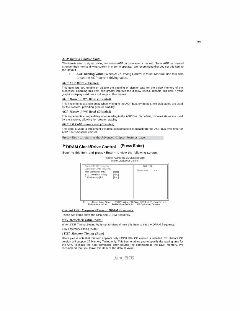
AGP Driving Control (Auto)This item is used to signal driving current on AGP cards to auto or manual. Some AGP cards needstronger than normal driving current in order to operate. We recommend that you set this item tothe default.
• AGP Driving Value: When AGP Driving Control is to set Manual, use this itemto set the AGP current driving value.
AGP Fast Write (Disabled)This item lets you enable or disable the caching of display data for the video memory of theprocessor. Enabling this item can greatly improve the display speed. Disable this item if yourgraphics display card does not support this feature.
AGP Master 1 WS Write (Disabled)This implements a single delay when writing to the AGP Bus. By default, two-wait states are usedby the system, providing greater stability.
AGP Master 1 WS Read (Disabled)This implements a single delay when reading to the AGP Bus. By default, two-wait states are usedby the system, allowing for greater stability
AGP 3.0 Calibration cycle (Disabled)This item is used to implement dynamic compensation to recalibrate the AGP bus over time forAGP 3.0 compatible chipset.
Press <Esc> to return to the Advanced Chipset Features page.
DRAM Clock/Drive ControlScroll to this item and press <Enter> to view the following screen:
(Press Enter)
Current CPU FrequencyCurrent DRAM FrequencyMax Memclock (Mhz) [Auto]1T/2T Memory Timing [Auto]CAS# latency (Tcl) [Auto]
Item Help
Menu Level
Phoenix-AwardBIOS CMOS Setup UtilityDRAM Clock/Drive Control
Current CPU Frequency/Current DRAM FrequencyThese two items show the CPU and DRAM frequency.
F5:Previous Values F6:Fail-Safe Defaults F7:Optimized Defaults: Move Enter: Select +/-/PU/PD:Value F10:Save ESC:Exit F1: General Help
Max Memclock (Mhz)(Auto)When DDR Timing Setting by is set to Manual, use this item to set the DRAM frequency.1T/2T Memory Timing (Auto)
1T/2T Memory Timing (Auto)Users please note that this item appears only if CPU after CG version is installed. CPU before CGversion will support 1T Memory Timing only. This item enables you to specify the waiting time forthe CPU to issue the next command after issuing the command to the DDR memory. Werecommend that you leave this item at the default value.

34
Using BIOS
Press <Esc> to return to the Advanced Chipset Features page.
LDT & PCI Bus Control (Press Enter)Scroll to this item and press <Enter> to view the following screen:
LDT Bus Frequency [800 MHz]PCI Delay Transaction [Disabled]
Item Help
Menu Level
Phoenix-AwardBIOS CMOS Setup UtilityLDT & PCI Bus Control
F5:Previous Values F6:Fail-Safe Defaults F7:Optimized Defaults: Move Enter: Select +/-/PU/PD:Value F10:Save ESC:Exit F1: General Help
LDT Bus Frequency (800MHz)This option allows you to specify the maximum operating frequency for the LDT transmitter clock.
PCI Delay Transaction (Disabled)The motherboard’s chipset has an embedded 32-bit post write buffer to support delay transactionscycles. Select Enabled to support compliance with PCI specification version 2.1.
VLink Data Rate (8X)
Init Display First (PCI slot)
Use this item to specify whether your graphics adapter is installed in one of the PCI slotsor is integrated on the motherboard
This option allows you to select the data transfer rate between the Northbridge andSouthbridge chipsets.
Press <Esc> to return to the Advanced Chipset Features page.
CAS# latency (Tcl) (Auto)This item determines the operation of SDRAM memory CAS (column address strobe). It isrecommended that you leave this item at the default value. The 2T setting requires fastermemory that specifically supports this mode.

35
Using BIOS
Integrated Peripherals
These options display items that define the operation of peripheral components onthe system’s input/output ports.
VIA OnChip IDE Device (Press Enter)Scroll to this item and press <Enter> to view the following screen:
VIA OnChip IDE Device [Press Enter]VIA OnChip PCI Device [Press Enter]SuperIO Device [Press Enter]
Item Help
Menu Level
Phoenix-AwardBIOS CMOS Setup UtilityIntegrated Peripherals
F5:Previous Values F6:Fail-Safe Defaults F7:Optimized Defaults: Move Enter: Select +/-/PU/PD:Value F10:Save ESC:Exit F1: General Help
OnChip VIA SATA [Enabled]SATA Mode [IDE]IDE DMA transfer access [Enabled]OnChip IDE Channel0 [Enabled]OnChip IDE Channel1 [Enabled]IDE Prefetch Mode [Enabled]Primary Master PIO [Auto]Primary Slave PIO [Auto]Secondary Master PIO [Auto]Secondary Slave PIO [Auto]Primary Master UDMA [Auto]Primary Slave UDMA [Auto]Secondary Master UDMA [Auto]Secondary Slave UDMA [Auto]IDE HDD Block Mode [Enabled]
Item Help
Menu Level
Phoenix-AwardBIOS CMOS Setup UtilityVIA OnChip IDE Device
F5:Previous Values F6:Fail-Safe Defaults F7:Optimized Defaults: Move Enter: Select +/-/PU/PD:Value F10:Save ESC:Exit F1: General Help
OnChip VIA SATA (Enabled)This option allows you to enable or disable the onboard Serial ATA device.
SATA Mode (IDE)Use this item to select the mode of Serial ATA
IDE DMA transfer access (Enabled)This item allows you to enable the transfer access of the IDE DMA then burst onto the PCI bus andnonburstable transactions do not.
On-Chip IDE Channel 0/1 (Enabled)Use these items to enable or disable the PCI IDE channels that are integrated on the motherboard.
IDE Prefetch Mode (Enabled)The onboard IDE drive interface supports IDE prefetching, for faster drive access. If you installa primary and secondary add-in IDE interface, set this field to Disabled if the interface does notsupport prefetching.

36
Using BIOS
Primary/Secondary Master/Slave PIO (Auto)Each IDE channel supports a master device and a slave device. These four items let you assignthe kind of PIO (Programmed Input/Output) was used by the IDE devices. Choose Auto to let thesystem auto detect which PIO mode is best, or select a PIO mode from 0-4.
Primary/Secondary Master/Slave UltraDMA (Auto)Each IDE channel supports a master device and a slave device. This motherboard supportsUltraDMA technology, which provides faster access to IDE devices.If you install a device that supports UltraDMA, change the appropriate item on this list to Auto. Youmay have to install the UltraDMA driver supplied with this motherboard in order to use an UltraDMAdevice.
IDE HDD Block Mode (Enabled)Enable this field if your IDE hard drive supports block mode. Block mode enables BIOS toautomatically detect the optimal number of block read and writes per sector that the drive cansupport and improves the speed of access to IDE devices.
AC97 Audio (Auto)Enables and disables the onboard audio chip. Disable this item if you are going to install a PCIaudio add-in card.
MC97 Modem (Auto)Enables and disables the onboard modem. Disable this item if you are going to install an externalmodem.
OnChip VIA LAN Device (Enabled)Enables and disables the onboard LAN.
OnChip VIA LAN Boot ROM (Disabled)Enables and disables the booting from the onboard LAN or a network add-in card with a remote bootROM installed.
OnChip USB Controller (All Enabled)Enable this item if you plan to use the Universal Serial Bus ports on this motherboard.
Press <Esc> to return to the Integrated Peripherals page.
VIA OnChip PCI Device (Press Enter)Scroll to this item and press <Enter> to view the following screen:
AC97 Audio [Auto]MC97 Modem [Auto]Onchip VIA LAN Device [Enabled]Onchip VIA LAN Boot ROM [Disabled]OnChip USB Controller [All Enabled]USB 2.0 Support [Enabled]USB Legacy Support [Enabled]USB Mouse Support [Enabled]
Item Help
Menu Level
Phoenix-AwardBIOS CMOS Setup UtilityVIA OnChip PCI Device
F5:Previous Values F6:Fail-Safe Defaults F7:Optimized Defaults: Move Enter: Select +/-/PU/PD:Value F10:Save ESC:Exit F1: General Help

37
Using BIOS
USB Legacy Support (Enabled)This item allows the BIOS to interact with a USB keyboard or mouse to work with MS-DOS basedutilities and non-Windows modes.
USB Mouse Support (Enabled)Enables this item if you plan to use a mouse connected through the USB port in a legacy operatingsystem (such as DOS) that does not support Plug and Play.
Onboard FDC Controller (Enabled)This option enables the onboard floppy disk drive controller.
Onboard Serial Port 1 (3F8/IRQ4)This option is used to assign the I/O address and interrupt request (IRQ) for onboard serial port 1(COM1).
Onboard Serial Port 2 (2F8/IRQ3)This option is used to assign the I/O address and interrupt request (IRQ) for onboard serial port 2(COM2).
UART Mode Select (Normal)This field is available if the Onboard Serial Port 2 field is set to any option but Disabled. UART ModeSelect enables you to select the infrared communication protocol-Normal (default), IrDA, or ASKIR.IrDA is an infrared communication protocol with a maximum baud rate up to 115.2K bps. ASKIR isSharp’s infrared communication protocol with a maximum baud rate up to 57.6K bps.
UR2 Duplex Mode (Half)This field is available when UART 2 Mode is set to either ASKIR or IrDA. This item enables you todetermine the infrared function of the onboard infrared chip. The options are Full and Half (default).Full-duplex means that you can transmit and send information simultaneously. Half-duplex is thetransmission of data in both directions, but only one direction at a time.
Onboard Parallel Port (378/IRQ7)This option is used to assign the I/O address and interrupt request (IRQ) for the onboard parallelport.
Press <Esc> to return to the Integrated Peripherals page.
SuperIO Device (Press Enter)
Onboard FDC Controller [Enabled]Onboard Serial Port 1 [3F8/IRQ4]Onboard Serial Port 2 [2F8/IRQ3]UART Mode Select [Normal]UR2 Duplex Mode [Half]Onboard Parallel Port [378/IRQ7]Parallel Port Mode [ECP]ECP Mode Use DMA [3]
Item Help
Menu Level
Phoenix-AwardBIOS CMOS Setup UtilitySuperIO Device
F5:Previous Values F6:Fail-Safe Defaults F7:Optimized Defaults: Move Enter: Select +/-/PU/PD:Value F10:Save ESC:Exit F1: General Help
USB 2.0 Support (Enabled)Enable this item if your system supports USB 2.0.
Scroll to this item and press <Enter> to view the following screen:

38
Using BIOS
Parallel Port Mode (ECP)Enables you to set the data transfer protocol for your parallel port. There are four options: SPP(Standard Parallel Port), EPP (Enhanced Parallel Port), ECP (Extended Capabilities Port) and ECP+EPP.SPP allows data output only. Extended Capabilities Port (ECP) and Enhanced Parallel Port (EPP) arebi-directional modes, allowing both data input and output. ECP and EPP modes are only supportedwith EPP- and ECP-aware peripherals.
ECP Mode Use DMA (3)When the onboard parallel port is set to ECP mode, the parallel port can use DMA 3 or DMA 1.
Power Management SetupThis option lets you control system power management. The system has various power-saving modes including powering down the hard disk, turning off the video, suspendingto RAM, and software power down that allows the system to be automatically resumedby certain events.
Press <Esc> to return to the Integrated Peripherals page.
HDD Power Down [Disabled]The IDE hard drive will spin down if it is not accessed within a specified length of time.
Suspend Mode [Disabled]The CPU clock will be stopped and the video signal will be suspended if no PowerManagement events occur for a specified length of time. Full power function will returnwhen a Power Management event is detected.Video Off Option (Suspend —> Off)This option defines if the video is powered down when the system is put into suspendmode.
Video Off Method (V/H SYNC+Blank)This selection will cause the system to turn off the vertical and horizontal synchroniza-tion ports and write blanks to the video buffer.
MODEM Use IRQ (3)If you want an incoming call on a modem to automatically resume the system from apower-saving mode, use this item to specify the interrupt request line (IRQ) that is usedby the modem. You might have to connect the fax/modem to the motherboard Wake OnModem connector for this feature to work.
Soft-Off by PWRBTN (Instant-Off)
HDD Power Down [Disable]Suspend Mode [Disable]Video Off Option [Suspend -> Off]Video Off Method [V/H SYNC+Blank]MODEM Use IRQ [3]Soft-Off by PWRBTN [Instant-Off]Power on After Power fail [Off]AMD K8 Cool’n’Quiet control [Auto]IRQ/Event Activity Detect [Press Enter]
Item Help
Menu Level
Phoenix-AwardBIOS CMOS Setup UtilityPower Management Setup
F5:Previous Values F6:Fail-Safe Defaults F7:Optimized Defaults: Move Enter: Select +/-/PU/PD:Value F10:Save ESC:Exit F1: General Help

39
Using BIOS
Under ACPI (Advanced Configuration and Power management Interface) you can createa software power down. In a software power down, the system can be resumed by WakeUp Alarms. This item lets you install a software power down that is controlled by thepower button on your system. If the item is set to Instant-Off, then the power buttoncauses a software power down. If the item is set to Delay 4 Sec. then you have to holdthe power button down for four seconds to cause a software power down.
Phoenix-AwardBIOS CMOS Setup UtilityIRQ/Event Activity Detect
VGA [OFF]LPT & COM [LPT/COM]HDD & FDD [ON]PCI Master [OFF]PowerOn by PCI Card [Enabled]Modem Ring Resume [Disabled]RTC Alarm Resume [Disabled]Date (of Month) 0Resume Time (hh: mm: ss) 0 : 0 : 0IRQs Activity Monitoring [Press Enter]
Item Help
Menu Level
XX
When Select Password,Please press ENTERkey to change PasswordMax 8 numbers.
F5:Previous Values F6:Fail-Safe Defaults F7:Optimized Defaults: Move Enter: Select +/-/PU/PD:Value F10:Save ESC:Exit F1: General Help
PWRON After PWR-Fail (Off)This item enables your computer to automatically restart or return to its last operating.
AMD K8 Cool’n’Quiet control (Auto)This item helps the system to lower the frequency when CPU idles. When the frequencydecreases, the temperature will drop automatically as well.
VGA (Off)When set to On, the system power will resume the system from a power saving mode if there isany VGA activity.
LPT & COM (LPT/COM )When this item is enabled, the system will restart the power-saving timeout counters when anyactivity is detected on the serial ports, or the parallel port.
HDD & FDD (ON)When this item is enabled, the system will restart the power-saving timeout counters when anyactivity is detected on the hard disk drive or the floppy diskette drive.
PCI Master (OFF)When set to Off, any PCI device set as the Master will not power on the system.PowerOn by PCI Card (Enabled)Use this item to enable PCI activity to wakeup the system from a power saving mode.
Modem Ring Resume (Disabled)Use this item to enable modem activity to wakeup the system from a power saving mode.
RTC Alarm Resume (Disabled)When set to Enabled, additional fields become available and you can set the date (day of themonth), hour, minute and second to turn on your system. When set to 0 (zero) for the day of themonth, the alarm will power on your system every day at the specified time.
Scroll to this item and press <Enter> to view the following screen:
IRQ/Event Activity Detect (Press Enter)

40
Using BIOS
Press <Esc> to return to the Integrated Peripherals page.
Set any IRQ to Enabled to allow activity at the IRQ to wake up the system from a power savingmode.
Press <Esc> to return to the IRQ/Event Activity Detect page.
IRQs Activity Monitoring (Press Enter)This screen enables you to set IRQs that will resume the system from a power saving mode.
Phoenix-AwardBIOS CMOS Setup UtilityIRQs Activity Monitoring
Primary INTR [ON]IRQ3 (COM2) [Disabled]IRQ4 (COM1) [Enabled]IRQ5 (LPT2) [Enabled]IRQ6 (Floppy Disk) [Enabled]IRQ7 (LPT1) [Enabled]IRQ8 (RTC Alarm) [Disabled]IRQ9 (IRQ2 Redir) [Disabled]IRQ10 (Reserved) [Disabled]IRQ11 (Reserved) [Disabled]IRQ12 (PS/2 Mouse) [Enabled]IRQ13 (Coprocessor) [Enabled]IRQ14 (Hard Disk) [Enabled]IRQ15 (Reserved) [Disabled]
Item Help
Menu Level
F5:Previous Values F6:Fail-Safe Defaults F7:Optimized Defaults: Move Enter: Select +/-/PU/PD:Value F10:Save ESC:Exit F1: General Help
PNP/PCI ConfigurationsThese options configure how PnP (Plug and Play) and PCI expansion cards operate inyour system. Both the the ISA and PCI buses on the motherboard use system IRQs(Interrup ReQuests) and DMAs (Direct Memory Access). You must set up the IRQ andDMA assignments correctly through the PnP/PCI Configurations Setup utility for themotherboard to work properly. Selecting PnP/PCI Configurations on the main programscreen displays this menu:
Phoenix-AwardBIOS CMOS Setup UtilityPnP/PCI Configurations
Reset Configuration Data [Disabled]
Resources Controlled By [Auto(ESCD)]IRQ Resources Press Enter
PCI/VGA Palette Snoop [Disabled]Assign IRQ For USB [Enabled]
Item Help
Menu Level
F5:Previous Values F6:Fail-Safe Defaults F7:Optimized Defaults: Move Enter: Select +/-/PU/PD:Value F10:Save ESC:Exit F1: General Help
XDefault is Disabled. SelectEnabled to reset Extended Sys-tem Configuration DataESCD) when you exit Setup ifyou have installed a new add-on and the systemreconfiguration has causedsuch a serious conflict that theOS cannot boot
Reset Configuration Data [Disabled]If you enable this item and restart the system, any Plug and Play configuration datastored in the BIOS Setup is cleared from memory.

41
Using BIOS
Resources Controlled By Auto [Auto(ESCD)]You should leave this item at the default Auto (ESCD). Under this setting, the systemdynamically allocates resources to Plug and Play devices as they are required.
If you cannot get a legacy ISA (Industry Standard Architecture) expansion card to workproperly, you might be able to solve the problem by changing this item to Manual, andthen opening up the IRQ Resources submenu.
• IRQ Resources [Press Enter]:In the IRQ Resources submenu, if you as-sign an IRQ to Legacy ISA, then that Interrupt Request Line is reserved for alegacy ISA expansion card. Press <Esc> to close the IRQ Resources submenu.
PCI/VGA Palette Snoop [Disabled]This item is designed to overcome problems that can be caused by some non-standardVGA cards. This board includes a built-in VGA system that does not require palettesnooping so you must leave this item disabled.
Assign IRQ For USB [Enabled]Names the interrupt request (IRQ) line assigned to the USB on your system. Activity ofthe selected IRQ always awakens the system.
F5:Previous Values F6:Fail-Safe Defaults F7:Optimized Defaults
Shutdown Temperature [Disabled]Enables you to set the maximum temperature the system can reach before poweringdown.
System Component CharacteristicsThese fields provide you with information about the systems current operating status.You cannot make changes to these fields.
PC Health StatusOn motherboards that support hardware monitoring, this item lets you monitor theparameters for critical voltages, temperatures and fan speeds.
Phoenix-AwardBIOS CMOS Setup UtilityPC Health Status
Shutdown Temperature [Disabled]CPU VcoreVcc 2.5VVcc 3.3VVcc 5.0V +12VVoltage BatterySystem TempCurrent CPU TempCPUFAN1 SpeedCASFAN1 Speed
Item Help
Menu Level
: Move Enter: Select +/-/PU/PD:Value F10:Save ESC:Exit F1: General Help

42
Using BIOS
Frequency/Voltage ControlThis item enables you to set the clock speed and system bus for your system. The clockspeed and system bus are determined by the kind of processor you have installed in yoursystem.
DIMM Voltage Adjust (2.60V)This item adjusts the voltage delivered to the DIMM memory.
Auto Detect PCI Clk (Enabled)When this item is enabled, BIOS will disable the clock signal of free PCI slots.
DIMM Voltage Adjust [2.60V]Auto Detect PCI Clk [Enabled]Spread Spectrum [Enabled]CPU Clock [200MHz]
Item Help
Menu Level
Phoenix-AwardBIOS CMOS Setup UtilityFrequency/Voltage Control
F5:Previous Values F6:Fail-Safe Defaults F7:Optimized Defaults: Move Enter: Select +/-/PU/PD:Value F10:Save ESC:Exit F1: General Help
Spread Spectrum (Enabled)If you enable spread spectrum, it can significantly reduce the EMI (Electro-MagneticInterference) generated by the system.
CPU Clock (200MHz)Use the CPU Host Clock to set the frontside bus frequency for the installed processor(Min 200 MHz, Max 232 MHz).
43
Using BIOS
Load Fail-Safe DefaultsThis option opens a dialog box that lets you install fail-safe defaults for all appropriateitems in the Setup Utility: Press <Y> and the <Enter> to install the defaults. Press<N> and then <Enter> to not install the defaults. The fail-safe defaults place no greatdemands on the system and are generally stable. If your system is not functioningcorrectly, try installing the fail-safe defaults as a first step in getting your system workingproperly again. If you only want to install fail-safe defaults for a specific option, selectand display that option, and then press <F6>.
Load Optimized DefaultsThis option opens a dialog box that lets you install optimized defaults for all appropriateitems in the Setup Utility. Press <Y> and then <Enter> to install the defaults. Press<N> and then <Enter> to not install the defaults. The optimized defaults place de-mands on the system that may be greater than the performance level of the components,such as the CPU and the memory. You can cause fatal errors or instability if you installthe optimized defaults when your hardware does not support them. If you only want toinstall setup defaults for a specific option, select and display that option, and then press<F7>.
Set Supervisor/User PasswordWhen this function is selected, the following message appears at the center of the screento assist you in creating a password.
ENTER PASSWORDType the password, up to eight characters, and press <Enter>. The password typed nowwill clear any previously entered password from CMOS memory. You will be asked toconfirm the password. Type the password again and press <Enter>. You may also press<Esc> to abort the selection.To disable password, just press <Enter> when you are prompted to enter password. Amessage will confirm the password being disabled. Once the password is disabled, thesystem will boot and you can enter BIOS Setup freely.
PASSWORD DISABLEDIf you have selected “System” in “Security Option” of “BIOS Features Setup” menu,you will be prompted for the password every time the system reboots or any time you tryto enter BIOS Setup.If you have selected “Setup” at “Security Option” from “BIOS Features Setup” menu,you will be prompted for the password only when you enter BIOS Setup.
Supervisor Password has higher priority than User Password. You can use SupervisorPassword when booting the system or entering BIOS Setup to modify all settings. Alsoyou can use User Password when booting thesystem or entering BIOS Setup but can not modify any setting if Supervisor Passwordis enabled.

44
Using BIOS
Save & Exit SetupHighlight this item and press <Enter> to save the changes that you have made in theSetup Utility and exit the Setup Utility. When the Save and Exit dialog box appears,press <Y> to save and exit, or press <N> to return to the main menu.
Exit Without SavingHighlight this item and press <Enter> to discard any changes that you have made in theSetup Utility and exit the Setup Utility. When the Exit Without Saving dialog boxappears, press <Y> to discard changes and exit, or press <N> to return to the mainmenu.
If you have made settings that you do not want to save, use the “ExitWithout Saving” item and press <Y> to discard any changes you havemade.
This concludes Chapter 3. Refer to the next chapter for information on the softwaresupplied with the motherboard.

45
Using the Motherboard Software
Chapter 4
Using the Motherboard Software
About the Software CD-ROM
The support software CD-ROM that is included in the motherboard package contains all thedrivers and utility programs needed to properly run the bundled products. Below you can finda brief description of each software program, and the location for your motherboardversion. More information on some programs is available in a README file, located in thesame directory as the software.
Never try to install all software from folfer that is not specified for use with yourmotherboard.
Before installing any software, always inspect the folder for files named README.TXT,INSTALL.TXT, or something similar. These files may contain important information thatis not included in this manual.
Auto-installing under Windows 98/ME/2000/XP
The Auto-install CD-ROM makes it easy for you to install the drivers and software for yourmotherboard.
If the Auto-install CD-ROM does not work on your system, you can still installdrivers through the file manager for your OS (for example, Windows Ex-plorer). Refer to the Utility Folder Installation Notes later in this chapter.
The support software CD-ROM disc loads automatically under Windows 98/ME/2000/XP.When you insert the CD-ROM disc in the CD-ROM drive, the autorun feature will automati-cally bring up the install screen. The screen has three buttons on it, Setup, Browse CD andExit.
If the opening screen does not appear; double-click the file “setup.exe” in theroot directory.
46
Using the Motherboard Software
Setup Tab
Setup Click the Setup button to run the software installation program. Selectfrom the menu which software you want to install.
Browse CD The Browse CD button is the standard Windows command that allowsyou to open Windows Explorer and show the contents of the supportCD.
Before installing the software from Windows Explorer, look for a filenamed README.TXT, INSTALL.TXT or something similar. This filemay contain important information to help you install the softwarecorrectly.
Some software is installed in separate folders for different operatingsystems, such as DOS, WIN NT, or WIN98/95. Always go to the correctfolder for the kind of OS you are using.
In install the software, execute a file named SETUP.EXE or INSTALL.EXEby double-clicking the file and then following the instructions on thescreen.
Exit The EXIT button closes the Auto Setup window.
Application TabLists the software utilities that are available on the CD.
Read Me TabDisplays the path for all software and drivers available on the CD.
Running SetupFollow these instructions to install device drivers and software for the motherboard:
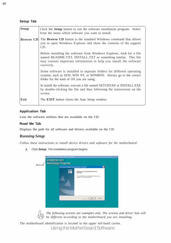
1. Click Setup. The installation program begins:
The following screens are examples only. The screens and driver lists willbe different according to the motherboard you are installing.
The motherboard identification is located in the upper left-hand corner.
47
Using the Motherboard Software
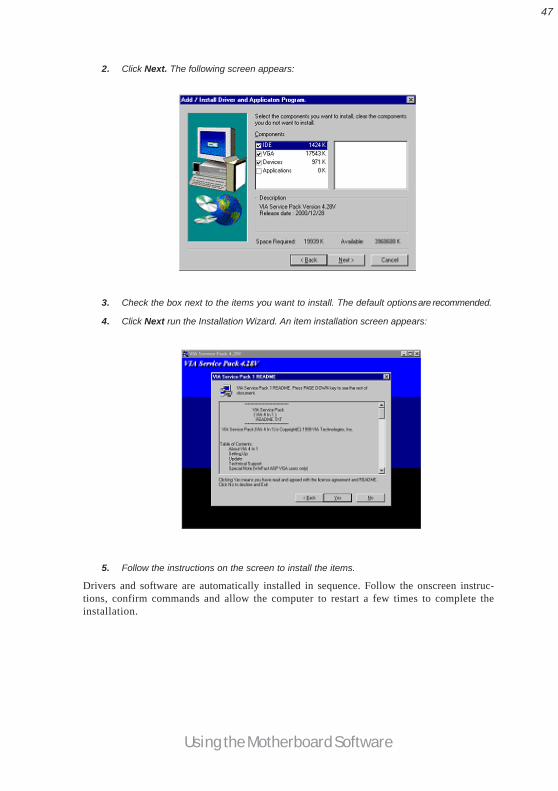
2. Click Next. The following screen appears:
3. Check the box next to the items you want to install. The default optionsare recommended.
4. Click Next run the Installation Wizard. An item installation screen appears:
5. Follow the instructions on the screen to install the items.
Drivers and software are automatically installed in sequence. Follow the onscreen instruc-tions, confirm commands and allow the computer to restart a few times to complete theinstallation.
48
Using the Motherboard Software
Manual InstallationInsert the CD in the CD-ROM drive and locate the PATH.DOC file in the root directory.This file contains the information needed to locate the drivers for your motherboard.
Look for the chipset and motherboard model; then browse to the directory and path tobegin installing the drivers. Most drivers have a setup program (SETUP.EXE) that auto-matically detects your operating system before installation. Other drivers have the setupprogram located in the operating system subfolder.
If the driver you want to install does not have a setup program, browse to the operatingsystem subfolder and locate the readme text file (README.TXT or README.DOC) forinformation on installing the driver or software for your operating system.
Utility Software ReferenceAll the utility software available from this page is Windows compliant. They are providedonly for the convenience of the customer. The following software is furnished under licenseand may only be used or copied in accordance with the terms of the license.
These software(s) are subject to change at anytime without prior notice.Please refer to the support CD for available software.
AMI/AWARD Flash Memory UtilityThis utility lets you erase the system BIOS stored on a Flash Memory chip on the motherboard,and lets you copy an updated version of the BIOS to the chip. Proceed with caution whenusing this program. If you erase the current BIOS and fail to write a new BIOS, or write anew BIOS that is incorrect, your system will malfunction. Refer to Chapter 3, Using BIOS formore information.
WinFlash UtilityThe Award WinFlash utility is a Windows version of the DOS Award BIOS flash writer utility.The utility enables you to flash the system BIOS stored on a Flash Memory chip on themotherboard while in a Windows environment. This utility is currently available forWINXP\ME\2000\98SE. To install the WinFlash utility, run WINFLASH.EXE from thefollowing directory: \UTILITY\WINFLASH 1.51
This concludes Chapter 4. Refer to the next chapter for information about SATA RAIDSetup.

49
VIA VT8237 SATA RAID Setup Guide
Chapter 5
VIA VT8237 SATA RAID Setup Guide
VIA RAID ConfigurationsThe motherboard includes a high performance Serial ATA RAID controller integrated in theVIA VT8237 Southbridge chipset. It supports RAID 0, RAID 1 and JBOD with two indepen-dent Serial ATA channels.
RAID: (Redundant Array of Independent Disk Drives) use jointly several hard drives toincrease data transfer rates and data security. It depends on the number of drives present andRAID function you select to fulfill the seurity or performance pruposes or both.
RAID 0 (called data striping) optimizes two identical hard disk drives to read and write datain parallel, interleaved stacks. Two hard disks perform the same work as a single drive but ata sustained data transfer rate, double that of a single disk alone, thus improving data accessand storage.
RAID 1 (called data mirroring) copies and maintains an identical image of data from onedrive to a second drive. If one drive fails, the disk array management software directs allapplications to the surviving drive as it contains a complete copy of the data in the otherdrive. This RAID configuration provides data protection and increases fault tolerance tothe entire system.
JBOD: (Just a Bunch of Drives) Also known as “Spanning”. Two or more hard drives arerequired. Several hard disk types configured as a single hard disk. The hard drives are simplyhooked up in series. This expands the capacity of your drive and results in a useable totalcapacity. However, JBOD will not increase any performance or data security.
Install the Serial ATA (SATA) hard disksThe VIA VT8237 Southbridge chipset supports Serial ATA hard disk drives. For optimalperformance, install identical drives of the same model and capacity when creating a RAIDset.
• If you are creating a RAID 0 (striping) array of performance, use two newdrives.
• If you are creating a RAID 1 (mirroring) array for protection, you can use twonew drives or use an existing drive and a new drive (the new drive must beof the same size or larger than the existing drive). If you use two drives ofdifferent sizes, the smaller capacity hard disk will be the base storage size.For example, one hard disk has an 80GB storage capacity and the other harddisk has 60GB storage capacity, the maximum storage capacity for the RAID1 set is 60GB.
Follow these steps to install the SATA hard disks for RAID configuration.
i Before setting up your new RAID array, verify the status of your hard disks.Make sure the Master/Slave jumpers are configured properly.
ii Both the data and power SATA cables are new cables. You cannot use older 40-pin80-conductor IDE or regular IDE power cables with Serial ATA drives. InstallingSerial ATA (SATA) hard disks require the use of new Serial ATA cable (4-conduc-tor) which supports the Serial ATA protocol and a Serial ATA power cable.
iii Either end of the Serial ATA data cable can be connected to the SATA hard disk orthe SATA connector on the motherboard.
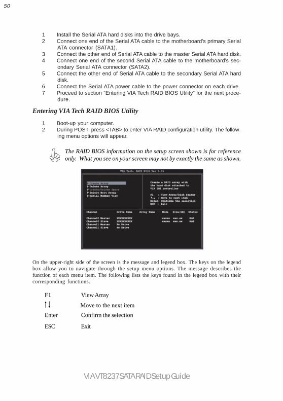
50
VIA VT8237 SATA RAID Setup Guide
1 Install the Serial ATA hard disks into the drive bays.2 Connect one end of the Serial ATA cable to the motherboard’s primary Serial
ATA connector (SATA1).3 Connect the other end of Serial ATA cable to the master Serial ATA hard disk.4 Connect one end of the second Serial ATA cable to the motherboard’s sec-
ondary Serial ATA connector (SATA2).5 Connect the other end of Serial ATA cable to the secondary Serial ATA hard
disk.6 Connect the Serial ATA power cable to the power connector on each drive.7 Proceed to section “Entering VIA Tech RAID BIOS Utility” for the next proce-
dure.
Entering VIA Tech RAID BIOS Utility
1 Boot-up your computer.2 During POST, press <TAB> to enter VIA RAID configuration utility. The follow-
ing menu options will appear.
On the upper-right side of the screen is the message and legend box. The keys on the legendbox allow you to navigate through the setup menu options. The message describes thefunction of each menu item. The following lists the keys found in the legend box with theircorresponding functions.
F1 View Array
Move to the next itemEnter Confirm the selection
ESC Exit
The RAID BIOS information on the setup screen shown is for referenceonly. What you see on your screen may not by exactly the same as shown.

51
VIA VT8237 SATA RAID Setup Guide
Create Array
1 In the VIA RAID BIOS utility main menu, select Create Array then press the<Enter> key. The main menu items on the upper-left corner of the screen arereplaced with create array menu options.
RAID 0 for performance
1 Select the second option item Array Mode, then press the <Enter> key. TheRAID system setting pop-up menu appears.
2 Select RAID 0 for performance from the menu and press <Enter>. From thispoint, you may choose to auto-configure the RAID array by selecting AutoSetup for Performance or manually configure the RAID array for strippedsets. If you want to manually configure the RAID array continue with nextstep, otherwise, proceed to step #5.
3 Select Select Disk Drives, then press <Enter>. Use arrow keys to selectdisk drive/s, then press <Enter> to mark selected drive. An asterisk is placedbefore the selected drive.
4 Select Block Size, then press <Enter> to set array block size. Lists of validarray block sizes are displayed on a pop-up menu.
For server systems, it is recommended to use a lowerarray block size. For multimedia computer systems usedmainly for audio and video editing, a higher array blocksize is recommended for optimum performance.
Use arrow keys to move selection bar on items and press <Enter> to select.
Tip

52
VIA VT8237 SATA RAID Setup Guide
5 Select Start Create Process and press <Enter> to setup hard disk for RAIDsystem. The following confirmation appears:
The same confirmation message appears when theAuto Setup for Performance option is selected.
Press “Y” to confirm or “N” to return to the configuration options.
RAID 1 for data protection
1 Select the second option item Array Mode, then press the <Enter> key. TheRAID system setting pop-up menu appears.
2 Select RAID 1 for data protection from the menu and press <Enter>. Selectnext task from pop-up menu. The task Create only creates the mirrored setwithout creating a backup. Create and duplicate creates both mirrored setand backup.
3 Select task and press <Enter>. The screen returns to Create Array menuitems. From this point, you may choose to auto-configure the RAID array byselecting Auto Setup for Data Security or manually configure the RAID arrayfor mirrored sets. If you want to manually configure the RAID array continuewith next step, otherwise, proceed to step #5.
4 Select Select Disk Drives, then press <Enter>. Use arrow keys to select diskdrive/s, then press <Enter> to mark selected drive. (An asterisk is placedbefore a selected drve.)
5 Select Start Create Process and press <Enter> to setup hard disk for RAIDsystem. The following confirmation message appears:
The same confirmation message appears when theAuto Setup for Performance option is selected.
Press “Y” to confirm or “N” to return to the configuration options.

53
VIA VT8237 SATA RAID Setup Guide
Delete Array1 In the VIA RAID BIOS utility main menu, select Delete Array then press the
<Enter> key. The focus is directed to the list of channel used for IDE RAIDarrays.
2 Press the <Enter> key to select a RAID array to delete. The following confir-mation message appears.
Press “Y” to confirm or “N” to return to the configuration options.
Select Boot Array
1 In the VIA RAID BIOS utility main menu, select Select Boot Array then press the<Enter> key. The focus is directed to the list of channel used for IDE RAIDarrays.
2 Press the <Enter> key to select a RAID array for boot. The Status of theselected array will change to Boot. Press <ESC> key to go return to menuitems. Follow the same procedure to deselect the boot array.
Serial Number View1 In the VIA RAID BIOS utility main menu, select Serial Number View then press
the <Enter> key. The focus is directed to the list of channel used for IDE RAIDarrays. Move the selection bar on each item and the serial number is dis-played at the bottom of the screen. This option is useful for identifying samemodel disks.

54
VIA VT8237 SATA RAID Setup Guide
Duplicate Critical RAID 1 ArrayWhen booting up the system, BIOS will detect if the RAID 1 array has any inconsistenciesbetween user data and backup data. If BIOS detects any inconsistencies, the status of thedisk array will be marked as critical, and BIOS will prompt the user to duplicate the RAID 1in order to ensure the backup data consistency with the user data.
If user selects Continue to boot, it will enable duplicating the array after booting into OS.
Rebuild Broken RAID 1 Array
When booting up the system, BIOS will detect if any member disk drives of RAID has failedor is absent. If BIOS detects any disk drive failures or missing disk drives, the status of thearray will be marked as broken.
If BIOS detects a broken RAID 1 array but there is a spare hard drive available for rebuildingthe broken array, the spare hard drive will automatically become the mirroring drive. BIOSwill show a main interface just like a duplicated RAID 1. Selecting Continue to bootenables the user to duplicate the array after booting into operating system.
If BIOS detects a broken RAID 1 array but there is no spare hard drive available forrebuilding the array, BIOS will provide several operations to solve such problems.

55
VIA VT8237 SATA RAID Setup Guide
1. Power off and Check the Failed Drive:
This item turns off the computer and replaces the failed hard drive with a good one. If yourcomputer does not support APM, you must turn off your computer manually. Afterreplacing the hard drive, boot into BIOS and select Choose replacement drive andrebuild to rebuild the broken array.
2. Destroy the Mirroring Relationship:
This item cancels the data mirroring relationship of the broken array. For broken RAID 1arrays, the data on the surviving disk will remain after the destroy operation. However,Destroy the Mirroring Relationship is not recommended because the data on theremaining disk will be lost when the hard drive is used to create another RAID 1 array.
3. Choose Replacement Drive and Rebuild:
This item enables users to select an already-connected hard drive to rebuild the broken array.After choosing a hard drive, the channel column will be activated.
Highlight the target hard drive and press <Enter>, a warning message will appear. Press Y touse that hard drive to rebuild, or press N to cancel. Please note selecting option Y willdestroy all the data on the selected hard drive.
4. Continue to boot:
This item enables BIOS to skip the problem and continue booting into OS.
56
VIA VT8237 SATA RAID Setup Guide
Installing RAID Software & DriversInstall Driver in Windows OS
New Windows OS (2000/XP/NT4) InstallationThe following details the installation of the drivers while installing Windows XP.
1 Start the installation:Boot from the CD-ROM. Press F6 when the message “Press F6 if you need toinstall third party SCSI or RAID driver’ appears.
2 When the Windows Setup window is generated, press S to specify anAdditional Device(s).
3 Insert the driver diskette VIA VT8237 Disk Driver into drive A: and press<Enter>.
4 Depending on your operation system, choose VIA Serial ATA RAID Con-troller (Windows XP), VIA Serial ATA RAID Controller (Windows 2000)or VIA Serial ATA RAID Controller (Windows NT4) from the list thatappears on Windows XP Setup screen, press the <Enter> key.
5 Press <Enter> to continue with installation or if you need to specify anyadditional devices to be installed, do so at this time. Once all devices arespecified, press <Enter> to continue with installation.
6 From the Windows XP Setup screen press the <Enter> key. Setup will nowload all device files and the continue the Windows XP installation.
Existing Windows XP Driver Installation1 Insert the ECS CD into the CD-ROM drive.2 The CD will auto-run and the setup screen will appear.3 Under the Driver tab, click on VIA SATA RAID Utility.4 The drivers will be automatically installed.
Confirming Windows XP Driver Installation
1 From Windows XP, open the Control Panel from My Computer followedby the System icon.
2 Choose the Hardware tab, then click the Device manager tab.3 Click the “+” in front of the SCSI and RAID Controllers hardware type. The
driver VIA IDE RAID Host Controller should appear.

57
VIA VT8237 SATA RAID Setup Guide
Installation of VIA SATA RAID UtilityThe VIA SATA RAID Utility is the software package that enables high-performance RAID0 arrays in the Windows*XP operating system. This version of VIA SATA RAID Utilitycontains the following key features:
• Serial ATA RAID driver for Windows XP• VIA SATA RAID utility• RAID0 and RAID1 functions
Insert the ECS CD and click on the Setup to install the software.
The InstallShield Wizard will begin automatically for installation. Click on the Nextbutton to proceed the installation in the welcoming window.

58
VIA VT8237 SATA RAID Setup Guide
Using VIA RAID ToolOnce the installation is complete, go to Start---> Programs---> VIA---> raid_tool.exe toenable VIA RAID Tool.
After the software is finished installation, it will automati-cally started every time Windows is initiated. You maydouble-click on the icon shown in the system trayof the tool bar to launch the VIA RAID Tool utility.
Put a check mark in the check box to install the feature you want. Then click Next buttonto proceed the installation.

59
VIA VT8237 SATA RAID Setup Guide
Click on or button to determine the viewing type of left windowpane. Thereare two viewing types: By controllers and by device. Click on the object in the leftwindowpane to display the status of the object in the right windowpane. The followingscreen shows the status of Array 0-RAID 0.
The main interface is divided into two windows and the toolbar above contain the mainfunctions. Click on these toolbar buttons to execute their specific functions. The leftwindowpane displays the controller and disk drives and the right windowpane displays thedetails of the controller or disk drives. The available features are as following:
View by Controller
View by Devices
View Event log
Help Topics
It means that VT8237 SATA RAID only has the feature of monitoring the statuses of RAID0 and RAID 1.

60
VIA VT8237 SATA RAID Setup Guide
You may also use the same or button to view the statuses of Array 0--
RAID 1.
Click on the plus (+) symbol next to Array 0--RAID 0 to see the details of each disk.

61
VIA VT8237 SATA RAID Setup Guide
Click on the plus (+) symbol next to Array 0; RAID 1 to see the details of each disk.