ECROS Technology · PDF file · 2007-11-22Introduction The Prius Mini-Scanner...
61
ECROS Technology www.ecrostech.com Prius Mini-Scanner User Manual Manual Revision Preliminary H for Firmware Version 0.62 March 30, 2004 This document is Copyright © 2004, ECROS Technology, All Rights Reserved. Prius is a trademark of Toyota Corporation. All other products and/or service names mentioned in this user manual may be trademarks of the companies with which they are associated.
Transcript of ECROS Technology · PDF file · 2007-11-22Introduction The Prius Mini-Scanner...

ECROS Technologywww.ecrostech.com
Prius Mini-Scanner
User Manual
Manual Revision Preliminary H
for Firmware Version 0.62
March 30, 2004
This document is Copyright © 2004, ECROS Technology, All Rights Reserved.
Prius is a trademark of Toyota Corporation. All other products and/or service namesmentioned in this user manual may be trademarks of the companies with which they are
associated.


Table of ContentsIntroduction..........................................................................................................................1
Road Safety..................................................................................................................... 1About this Manual...........................................................................................................1Outline of Operation........................................................................................................2Using the Data.................................................................................................................2Vehicle Model Years.......................................................................................................2
Installing the Prius Mini-Scanner........................................................................................ 3Unpacking the Mini-Scanner.......................................................................................... 3Tools and Supplies.......................................................................................................... 3Concealing the Adapter Cable.........................................................................................3Plugging in the DLC Adapter..........................................................................................5Installing the Main Unit.................................................................................................. 6Adjusting the Display......................................................................................................7Securing the Main Unit in the Car.................................................................................. 8Checking the Mini-Scanner.............................................................................................8The Serial Port.................................................................................................................9Mini-Scanner Firmware................................................................................................ 10Uninstalling the Mini-Scanner...................................................................................... 10
Basic Operation..................................................................................................................10Turning the Mini-Scanner On and Off.......................................................................... 10The Display Backlight...................................................................................................11
Left, Middle and Right Buttons......................................................................................... 11Button Functions........................................................................................................... 11Tap and Hold.................................................................................................................12Modes............................................................................................................................12Selecting Data Items to Display.................................................................................... 12Introducing “Slots”........................................................................................................12Selecting Display Items.................................................................................................13Setting and Saving Favorite Items.................................................................................14Using Favorite Slots...................................................................................................... 14
Choosing Options...............................................................................................................15Prius Mini-Scanner Options..........................................................................................16
Logging Data via the Serial Port........................................................................................18Timestamp.....................................................................................................................18Log Format.................................................................................................................... 19Creating a Chart in a Spreadsheet................................................................................. 19Control of Logging........................................................................................................20
Trouble Codes Mode..........................................................................................................20Browsing ECUs.............................................................................................................20Interpreting DTCs..........................................................................................................21Leaving Trouble Codes Mode.......................................................................................21Clearing DTCs...............................................................................................................21
Updating Mini-Scanner Firmware..................................................................................... 22Downloading Firmware.................................................................................................22The Flash Loader .........................................................................................................23Power to the Mini-Scanner............................................................................................23Connecting the Serial Cable..........................................................................................24Terminal Emulator Programs........................................................................................ 24Firmware Update Procedure..........................................................................................27

Problems and Errors...................................................................................................... 28Flash Loader Errors....................................................................................................... 30Advanced Use of the Flash Loader............................................................................... 31Expert Use of the Flash Loader.....................................................................................31Summary of Button Functions...................................................................................... 32
Appendix A - Available Data Items...................................................................................32Listing of Data Items.....................................................................................................33
Appendix B - Prius Diagnostic Trouble Codes..................................................................41Battery ECU Diagnostic Trouble Codes....................................................................... 41Engine ECU Diagnostic Trouble Codes........................................................................42Hybrid Vehicle ECU Diagnostic Trouble Codes.......................................................... 45

IntroductionThe Prius Mini-Scanner displays informationon the operation of a Toyota Prius gasoline /electric hybrid car. You can use the informa-tion to drive the car as economically as possi-ble, to understand how it works and to watchfor any problems that might develop.
The Mini-Scanner obtains information fromthe various computers or “Electronic ControlUnits” (ECUs) in the car. It does this usingthe On-Board Diagnostic (OBD-II) data bus.All Prius have this, so no modifications arenecessary and installation is fully reversible.
You can position the Mini-Scanner behind the steering wheel where most cars have theirmain instrument cluster. The driver can then glance at the display without taking his orher eyes from the road for any longer than is usual. It is also possible to locate the Mini-Scanner for use by a passenger.
Over 50 data items can be retrieved from the car's ECUs and displayed. Some representvehicle operating data that would be present in any car, such as engine r.p.m. and coolanttemperature. Other items are specific to a gasoline / electric hybrid vehicle, such as thebattery state-of-charge and current and the torque of the traction motor. Finally, manyitems give you diagnostic and trouble-shooting information, such as the temperature ofthe motors, battery and inverter electronics. The Mini-Scanner can retrieve “DiagnosticTrouble Codes” (DTCs) from the main ECUs. This is the information that Toyota servicecenters use to locate problems with the vehicle.
Road SafetyWhen installed and used properly, the Prius Mini-Scanner should be no more distractingto the driver than the speedometer or Multi-Function Display. Do not try to use the Mini-Scanner when it is not properly secured or mount it in such a way that the driver musttake his or her eyes off the road for more than a moment. I strongly recommend that thedriver not use the buttons while the car is moving. To study the displayed informationclosely in this situation, have someone else drive the car and operate the Mini-Scannerfrom a passenger seat. A long adapter cable is available as an accessory for this purpose.
However you choose to use the Mini-Scanner, I accept no responsibility for any failure todrive your car in a safe manner. If you find the Mini-Scanner distracting to the driver,please return it for a refund of the purchase price.
About this ManualIn this User Manual, I will tell you how to install, operate and look after your Prius Mini-Scanner. All the information you can get from your car is described. In many cases itsrelevance to owning and driving your Prius is explained. But, before we plunge into thedetailed stuff, let's take a quick look at how the Mini-Scanner works and think about whatwe might do with the data it will give us. If you are desperate to plug the Mini-Scanner inand start it up, follow the procedure in the printed Read Me First / Quick Start Guide.
Page 1
Photo 1 – The Mark II Prius Mini-Scanner

Outline of OperationMany of the ECUs in the Prius are connected to a data bus or network called the OBD IIbus (On-Board Diagnostics, version 2). The main purpose of this bus is to allow servicepersonnel using special equipment to get information that helps them diagnose problemswith the car. The ECUs do not “talk” to each other on this bus. Rather, a “tester” devicemust be connected to the bus which sends messages to the ECUs requesting that theysend back specific data. The tester plugs into a “Data Link Connector 3” (DLC3) whichis under the dash near the driver's left knee. Toyota service centers use a “Toyota Hand-Held Tester” or THHT to “talk” to the car's ECUs and monitor the vehicle's operation.
When you plug the Mini-Scanner into the Prius DLC3 and turn it on, it sends a signal onthe OBD II bus to “wake up” the ECUs and then begins requesting data items. Repliesfrom the ECUs are decoded and the data is presented on the display. Much of what youwill find in this User Manual has to do with choosing the data items to be requested andcontrolling how and when they are displayed.
As well as displaying the data from the ECU replies, the Mini-Scanner sends them to aserial port (which is like the “COM” port on a personal computer). By connecting a PCor a PDA to this serial port, you can store or “log” the data for analysis at some later time.
Using the DataThe information that the Prius Mini-Scanner gives you access to is useful in three ways:
• You can learn how to drive the car most efficiently.
• With some technical inclination, you can learn how the car works in various situations.
• You can watch for any problems that might develop and if the “check engine” lightcomes on you can take steps to find out why.
Details of the second and third topics are contained in the body of this User Manual, butthe first deserves a little space here. The Prius achieves its remarkable fuel economy inpart by shutting down the engine in city driving and recovering energy during braking tocharge the battery. Both these functions are subject to technical limits. If the engine hasturned off, a little too much pressure on the accelerator pedal will start it up again. Toomuch pressure on the brake pedal will engage the friction brakes, wasting energy insteadof putting it back in the battery. Using the battery current and state-of-charge displayedby the Mini-Scanner, you can see when you are approaching these limits and over timechange the way you drive to avoid them and improve your fuel economy.
Vehicle Model YearsThe Prius Mini-Scanner works with North American and European Prius from the 2001to 2003 model years. It does not work with first-generation Prius nor has it been testedwith second-generation Prius sold in Japan.
In the third generation Prius, starting with model year 2004, Toyota no longer use theOBD II bus for service diagnostics. Only legally mandated information, mostly related toemissions testing, is available on that bus. All the interesting data has been removed tothe Controller Area Network (CAN) bus. The Mini-Scanner does not work with the 2004model year Prius. All the work of figuring out how to get the data from the car needs tobe done again before a Mini-Scanner-like device can be made for that car.
Page 2
Installing the Prius Mini-ScannerIn this chapter of the User Manual, I describe the installation of the Mini-Scanner in yourcar. I will assume that you want to fix the Mini-Scanner behind the steering wheel. Ifthis isn't the case, you'll need to adapt these instructions to your needs. You should stillread this section of the manual to find out how to correctly connect the cables. The levelof detail I give is intended to allow people with no experience of electronic equipment tocomplete the installation with ease. I apologize if this makes tedious reading for some ofyou.
Installation as described here is completely reversible. No holes are drilled, wires cut (oreven spliced) and nothing is stuck to the car. If you take the Mini-Scanner out of the car,it is impossible to tell that it was ever there.
All instructions are written with reference to a left-hand drive vehicle. Owners of right-hand drive vehicles should experience no particular problems adapting them.
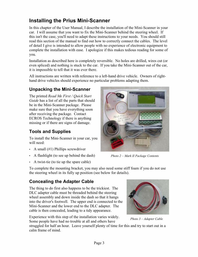
Unpacking the Mini-ScannerThe printed Read Me First / Quick StartGuide has a list of all the parts that shouldbe in the Mini-Scanner package. Pleasemake sure that you have everything soonafter receiving the package. ContactECROS Technology if there is anythingmissing or if there are signs of damage.
Tools and SuppliesTo install the Mini-Scanner in your car, youwill need:
• A small (#1) Phillips screwdriver
• A flashlight (to see up behind the dash)
• A twist-tie (to tie up the spare cable)
To complete the mounting bracket, you may also need some stiff foam if you do not usethe steering wheel in its fully up position (see below for details).
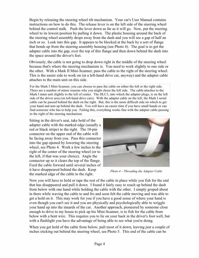
Concealing the Adapter CableThe thing to do first also happens to be the trickiest. TheDLC adapter cable must be threaded behind the steeringwheel assembly and down inside the dash so that it hangsinto the driver's footwell. The upper end is connected to theMini-Scanner and the lower end to the DLC adapter. Thecable is then concealed, leading to a tidy appearance.
Experience with this step of the installation varies widely.Some people have had no trouble at all and others havestruggled for half an hour. Leave yourself plenty of time for this and try to start out in acalm frame of mind.
Page 3
Photo 2 – Mark II Package Contents
Photo 3 – Adapter Cable
Begin by releasing the steering wheel tilt mechanism. Your car's User Manual containsinstructions on how to do this. The release lever is on the left side of the steering wheelbehind the control stalk. Push the lever down as far as it will go. Now, put the steeringwheel to its lowest position by pulling it down. The plastic housing around the back ofthe steering wheel assembly drops away from the dash and you will see a gap of half aninch or so. Look into this gap. It appears to be blocked at the back by a sort of flangethat bends up from the steering assembly housing (see Photo 4). The goal is to get theadapter cable into the gap, over the top of this flange and then down behind the dash intothe space around the driver's feet.
Obviously, the cable is not going to drop down right in the middle of the steering wheelbecause that's where the steering mechanism is. You need to work slightly to one side orthe other. With a Mark II Mini-Scanner, pass the cable to the right of the steering wheel.This is the easier side to work on (in a left-hand drive car, anyway) and the adapter cableattaches to the main unit on this side.
For the Mark I Mini-Scanner, you can choose to pass the cable on either the left or the right side.There are a number of minor reasons why you might chose the left side. The cable attaches to theMark I main unit slightly to the left of center. The DLC3, into which the adapter plugs, is on the leftside of the driver area (on left-hand drive cars). With the adapter cable on the left, the Mark I serialcable can be passed behind the dash on the right. But, this is the more difficult side on which to getyour hand and arm up behind the dash. You will have an easier time if you have small hands or canfind someone who has to help you. Failing this, everything works fine with the adapter cable passingto the right of the steering mechanism.
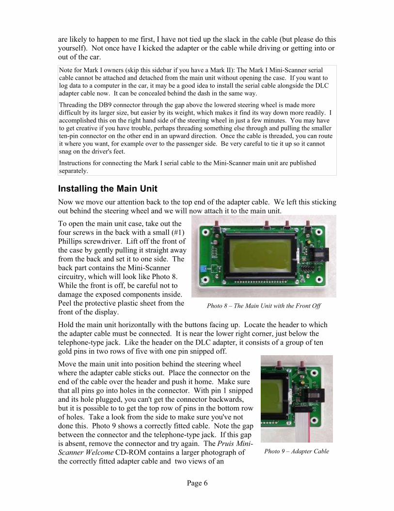
Sitting in the driver's seat, take hold of theadapter cable with the marked edge (usually ared or black stripe) to the right. The 10-pinconnector on the upper end of the cable willbe facing away from you. Pass this connectorinto the gap opened by lowering the steeringwheel, see Photo 4. Work a few inches to theright of the center of the steering wheel (or tothe left, if that was your choice). Angle theconnector up so it clears the top of the flange.Feed the cable forward until several inches ofit have disappeared behind the dash. Keepthe marked edge of the cable to the right.
Now you will have to hold or tape the rest of the cable in place while you fish for the endthat has disappeared and pull it down. I found it fairly easy to reach up behind the dashfrom below with one hand while holding the cable with the other. I simply groped aboutin there while waving the cable to and fro and soon felt the cable moving and was able toget a hold on it. This may work for you if you have a good sense of where your hand iseven though you can't see it and you are physically and psychologically able to wriggleyour hand up into the innards of the car. Another approach, pioneered by someone closeenough to drive to my house to pick up his Mini-Scanner, is to fish for the cable frombelow with a bent wire. This requires you to lie on your back in the driver's foot well, butwith a flashlight you have the advantage of being able to see what you're doing.
When you get hold of the cable from below, pull most of it down, leaving just a couple ofinches sticking out behind the steering wheel, see Photo 5. This end of the cable can be
Page 4
Photo 4 – Threading the Adapter Cable

jiggled into the right place to connect to theMini-Scanner main unit later. Check that themarked edge of the cable is still to the right andthat the 10-pin connector on the end of the cablefaces away from you towards the front of the car.
Plugging in the DLC AdapterThe DLC adapter should next be connected to the lower end of the adapter cable that ishanging into the driver's footwell. Hold the adapter with the red plug at the top andfacing towards you. Locate the “header” (a group of gold pins) in the lower right handcorner. The connector on the cable fits over these pins.
Put the connector over the header, making sure all the pinssticking up from the DLC adapter line up with holes in theconnector. As pin one is snipped off and its hole in theconnector is plugged up, it should not be possible to get thiswrong. Squeeze the connector and adapter firmly together.The edge of the cable marked with a red stripe will be to theright and the cable will lead directly away from the adapter(rather than folding over the top of the connector) as shownin Photo 6.
The Mark I DLC adapter is a little larger than the Mark II shown here, but installation is otherwisethe same. Original Mark 1s (not remanufactured) do not have pin one snipped off to prevent thecable from being installed incorrectly so a little more care is needed.
Locate the Diagnostic Link Connector (DLC or DLC3). To do this, kneel on the groundoutside the car next to the driver's side door. Duck your head into the pedal area and lookup underneath the lower edge of the dash. You will find the DLC fixed in a recess in theplastic dash molding. (Once you know where the DLC is, it will no longer be necessaryto kneel down to find it; you will be able to plug in the adapter by touch.)
Plug the DLC adapter into the DLC. It will only fit oneway. Turn the adapter so that the red connector faces upand is closer to you than the side to which cable is attached.As you do this, you will put a half-twist in the cable and themarked side will now be on the left. Tip the top of theadapter towards the front of the car and align the red plugwith the DLC. Press the adapter board firmly behind the red plug to seat it. Photo 7shows the DLC adapter and cable correctly installed. The pedal in the picture marked"push on/off" is the emergency brake.
You will need to tie up the slack in the adapter cable so that it does not get in the way ofthe driver's feet. The cable is 30 inches long, which allows some extra length for ease ofinstallation. This results in a loop falling in front of the pedals. Tie this up with a twist-tie or in some other convenient way. Don't tie it up so that the cable is tight, just so that itdoesn't hang down. You will need a little slack to install the main unit. It may be best tocome back to this after completing the installation, but don't forget it and get your foottangled in the cable when you drive the car.
If at this point you're wondering whether the DLC adapter will get in the driver's way, letme assure you that it has never got in my way. In fact, so that any problems in this area
Page 5
<<< new photo >>>Photo 5 – A Couple of Inches
Photo 6 – Mark II DLC Adapter
<<< new photo >>>Photo 7 – Connecting to the DLC
are likely to happen to me first, I have not tied up the slack in the cable (but please do thisyourself). Not once have I kicked the adapter or the cable while driving or getting into orout of the car.
Note for Mark I owners (skip this sidebar if you have a Mark II): The Mark I Mini-Scanner serialcable cannot be attached and detached from the main unit without opening the case. If you want tolog data to a computer in the car, it may be a good idea to install the serial cable alongside the DLCadapter cable now. It can be concealed behind the dash in the same way.
Threading the DB9 connector through the gap above the lowered steering wheel is made moredifficult by its larger size, but easier by its weight, which makes it find its way down more readily. Iaccomplished this on the right hand side of the steering wheel in just a few minutes. You may haveto get creative if you have trouble, perhaps threading something else through and pulling the smallerten-pin connector on the other end in an upward direction. Once the cable is threaded, you can routeit where you want, for example over to the passenger side. Be very careful to tie it up so it cannotsnag on the driver's feet.
Instructions for connecting the Mark I serial cable to the Mini-Scanner main unit are publishedseparately.
Installing the Main UnitNow we move our attention back to the top end of the adapter cable. We left this stickingout behind the steering wheel and we will now attach it to the main unit.
To open the main unit case, take out thefour screws in the back with a small (#1)Phillips screwdriver. Lift off the front ofthe case by gently pulling it straight awayfrom the back and set it to one side. Theback part contains the Mini-Scannercircuitry, which will look like Photo 8.While the front is off, be careful not todamage the exposed components inside.Peel the protective plastic sheet from thefront of the display.
Hold the main unit horizontally with the buttons facing up. Locate the header to whichthe adapter cable must be connected. It is near the lower right corner, just below thetelephone-type jack. Like the header on the DLC adapter, it consists of a group of tengold pins in two rows of five with one pin snipped off.
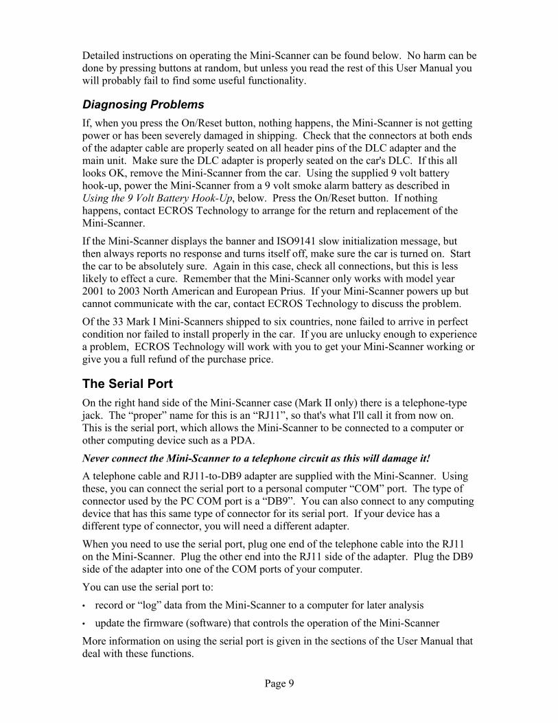
Move the main unit into position behind the steering wheelwhere the adapter cable sticks out. Place the connector on theend of the cable over the header and push it home. Make surethat all pins go into holes in the connector. With pin 1 snippedand its hole plugged, you can't get the connector backwards,but it is possible to to get the top row of pins in the bottom rowof holes. Take a look from the side to make sure you've notdone this. Photo 9 shows a correctly fitted cable. Note the gapbetween the connector and the telephone-type jack. If this gapis absent, remove the connector and try again. The Pruis Mini-Scanner Welcome CD-ROM contains a larger photograph ofthe correctly fitted adapter cable and two views of an
Page 6
Photo 8 – The Main Unit with the Front Off
Photo 9 – Adapter Cable

incorrectly fitted cable. Even if you turn on the car with the cable incorrectly fitted, youwill not damage anything; the Mini-Scanner just won't work.
Note that the marked edge of the cable is to the right and the cable leads directly downand away from the main unit and does not fold over the top of the connector.
Note for Mark I owners (skip this sidebar if you have a Mark II): If you have a Mark I Mini-Scanner,take account of the differences noted in this section when installing the main unit.
The Mark I case has loose end panels and you need to be careful not to lose them when you open thecase and to guide them back into their slots when you reassemble it.
The header to which the adapter cable must be connected is in a completely different place. It isslightly to the left of center on the lower edge of the circuit board and is labeled JP3. At the far right,there is another very similar header, labeled JP4, which is for the Mark I serial cable, not the adaptercable. If you connect the adapter cable to the wrong header you will not damage anything but theMini-Scanner will not work and the car will set the Check Engine Light.
The mounting bracket for the Mark I is fixed to the main unit by the bottom two screws that hold thecase together. Therefore, replace the two screws closest to the buttons first and remember to put thebracket in place before inserting the remaining two screws. The adapter cable passes underneath thebracket. Make sure it is lying flat and is not folded.
Adjusting the DisplayThe type of display used in the Mini-Scanner is a Liquid Crystal Display (LCD). So thatthe text is clearly readable from the normal viewing position, it may be necessary to makean adjustment to the “contrast” setting. It is not particularly critical, but since you cannotmake the adjustment once the case is closed up, you might want to fiddle with it now. Ofcourse, if you want the drill a small hole in the case, you will be able to adjust the contrastfrom outside. The contrast is set during manufacture and you may not need to change it.
Hold or prop up the Mini-Scanner where you will fix it in place and make sure it points inthe direction you desire (directly towards you when you are in the normal driving positionin most cases). Don't lean the unit so far back that it catches reflections of the sky in theglass front of the display. Turn it on by pressing the On/Reset button, which is on its ownat the left. With the car off, the Mini-Scanner will power up for about ten seconds, whichis long enough to evaluate the display. You can turn the car on if you want to; you don'tneed to start it. Look for dark text and a clear background.
To try different contrast settings, use your #1 Phillips screwdriver to adjust the small bluevariable resistor on the left hand edge of the circuit board, close to the bottom. Stick thescrewdriver in from the left and twist it very slightly. One direction will darken both thetext and background of the display and the other will lighten them. Find the setting that isbest for you when you are seated normally and the Mini-Scanner is where you want it tobe when you've secured it in place. I have found that the smallest degree of darkening ofthe background gives the best overall clarity. Use the border of the display, which staysclear for all settings, as a reference.
If you don't want to bother with this, the preset contrast will probably be just find for you.It is always possible to come back and adjust it later, but you will have to remove the topof the case again (unless you drill the hole).
Replace the front of the main unit case. Tip the main unit towards you, so that its facerests on the steering wheel housing. Replace the four screws that hold the case together.Tip the main unit back upright and you are ready to secure it in place.
Page 7

Securing the Main Unit in the CarYou may have your own ideas about how to fix the Mini-Scanner in place, especially ifyou don't want to put it behind the steering wheel. In this section, I assume you do wantit behind the steering wheel and also that you don't want to fix it directly to the car. Forother methods of fixing, adhesive-backed Velcro™ and/or double-sided foam tape willcome in handy, but are not included in the package.
The Mini-Scanner comes with a simple mounting bracket.The bottom of the bracket is intended to be trapped by thesteering wheel assembly when you lift it back up into place.The top of the bracket (the larger part) provides a surface towhich you can fix the back of the main unit case. It comeswith a large piece of foam tape attached which will not let goonce you've pressed the Mini-Scanner onto it. If you want tohave a second chance, you could replace it with Velcro or perhaps only remove part of thebacking to expose a smaller area of adhesive.
The padding on the bottom of the bracket as supplied will work if you use the steeringwheel in the fully up position. If you use a lower position, you will need to add somemore padding. A stiff foam is good for this, or you could use some more double-sidedfoam tape without removing the backing. The foam tape supplied here is not very sticky(unlike the tape on the top part!) and can be unwound for less padding. Only remove thebacking if you want some extra stick to hold it in place in the car or if you want to use itto secure extra padding.
With your left hand, hold the padded end of the bracket in the gap between the steeringwheel housing and the dash. With your right hand, raise the steering wheel into positionso that it traps the bracket. You can now release the bracket and use your left hand tolock the steering wheel into position. You may have to release, adjust and reinsert thebracket a number of times until the grip is firm at your preferred steering wheel heightand the top of the bracket is at a good angle for mounting the Mini-Scanner. The bracketcan be easily bent with your fingers.
Remove (all or part) of the backing from the large piece of foam tape. Move the Mini-Scanner main unit up towards the bracket, guiding any spare adapter cable back behindthe dash so that it is hidden. When you are happy with the position of the bracket and themain unit, allow them to touch. Press the main unit back against the bracket. By puttingyour fingers behind the main unit, you can press them together more firmly, or you candrop the steering wheel, take the assembly out to do this and then put it back.
Make sure that cables falling below the dash are tied up out of the way of the driver's feet.Your Mini-Scanner is now installed!
Checking the Mini-ScannerTo check that your Mini-Scanner is installed and working properly, turn it on by pressingthe On/Reset button. This is on the top at the far left hand side. The display will showthe firmware version, for example “Mini-Scanner: 0.61”, and then below it the message“ISO9141 Slow Init...”. If the car is not turned on, after a few seconds the display willchange to “Slow Init: no resp.” and soon after that, the Mini-Scanner will turn itself off. Ifthe car is turned on, the display will begin showing data being retrieved from the ECUs.
Page 8
Photo 10 – Mounting Bracket
Detailed instructions on operating the Mini-Scanner can be found below. No harm can bedone by pressing buttons at random, but unless you read the rest of this User Manual youwill probably fail to find some useful functionality.
Diagnosing ProblemsIf, when you press the On/Reset button, nothing happens, the Mini-Scanner is not gettingpower or has been severely damaged in shipping. Check that the connectors at both endsof the adapter cable are properly seated on all header pins of the DLC adapter and themain unit. Make sure the DLC adapter is properly seated on the car's DLC. If this alllooks OK, remove the Mini-Scanner from the car. Using the supplied 9 volt batteryhook-up, power the Mini-Scanner from a 9 volt smoke alarm battery as described inUsing the 9 Volt Battery Hook-Up, below. Press the On/Reset button. If nothinghappens, contact ECROS Technology to arrange for the return and replacement of theMini-Scanner.
If the Mini-Scanner displays the banner and ISO9141 slow initialization message, butthen always reports no response and turns itself off, make sure the car is turned on. Startthe car to be absolutely sure. Again in this case, check all connections, but this is lesslikely to effect a cure. Remember that the Mini-Scanner only works with model year2001 to 2003 North American and European Prius. If your Mini-Scanner powers up butcannot communicate with the car, contact ECROS Technology to discuss the problem.
Of the 33 Mark I Mini-Scanners shipped to six countries, none failed to arrive in perfectcondition nor failed to install properly in the car. If you are unlucky enough to experiencea problem, ECROS Technology will work with you to get your Mini-Scanner working orgive you a full refund of the purchase price.
The Serial PortOn the right hand side of the Mini-Scanner case (Mark II only) there is a telephone-typejack. The “proper” name for this is an “RJ11”, so that's what I'll call it from now on.This is the serial port, which allows the Mini-Scanner to be connected to a computer orother computing device such as a PDA.
Never connect the Mini-Scanner to a telephone circuit as this will damage it!A telephone cable and RJ11-to-DB9 adapter are supplied with the Mini-Scanner. Usingthese, you can connect the serial port to a personal computer “COM” port. The type ofconnector used by the PC COM port is a “DB9”. You can also connect to any computingdevice that has this same type of connector for its serial port. If your device has adifferent type of connector, you will need a different adapter.
When you need to use the serial port, plug one end of the telephone cable into the RJ11on the Mini-Scanner. Plug the other end into the RJ11 side of the adapter. Plug the DB9side of the adapter into one of the COM ports of your computer.
You can use the serial port to:
• record or “log” data from the Mini-Scanner to a computer for later analysis
• update the firmware (software) that controls the operation of the Mini-Scanner
More information on using the serial port is given in the sections of the User Manual thatdeal with these functions.
Page 9

Mini-Scanner FirmwareWhen it arrives, your Mini-Scanner contains the firmware that was most up-to-date at thetime of shipment. From time-to-time, new versions of the firmware may be released toadd functionality and/or correct problems. You will hear about this by e-mail. To takeadvantage of new releases of Mini-Scanner firmware, obtain a new firmware file andfollow the procedure described in the chapter Updating Mini-Scanner Firmware.
Uninstalling the Mini-ScannerThe Mini-Scanner has been designed so that you can leave it installed in your car forhowever long you wish. When it is off, it takes no power from the car and will notcontribute to battery drain. There will be times, however, when you want to uninstall theMini-Scanner either completely or partially. For example, the DLC adapter must beunplugged in order for a diagnostic tester to be connected to the car. Your dealer'sservice department may want to connect a tester and a technician performing emissionstesting will certainly need to do this. In these situations, you can simply unplug the DLCadapter from the car, but be sure not to leave it dangling in the way of the pedals.
You may not want to make it obvious to service technicians that you are using a scanner.If you unplug the DLC adapter from the car and from the adapter cable and take it away,there is nothing left to really suggest a connection to the DLC. You could also disconnectand remove the main unit if you think a technician might guess what is going on. Youcould also remove the adapter cable and leave no evidence at all (depending on how easyor difficult you found the installation of the cable!).
Should you decide to remove the main unit from the car, for example for a firmwareupload, it is perfectly safe to leave the DLC adapter and cable plugged in. You can drivethe car in this state. It is also safe to have the DLC adapter plugged in without the adaptercable attached. The Mini-Scanner has been designed not to present the risk of damage toyour car.
When disconnecting the adapter cable, always pull off the connector by grasping its bodyand pulling straight away from the header. Never pull on the ribbon cable itself as it willbecome detached from the connector. Replacement cables are available from ECROSTechnology. Removing the cable from the Mark II main unit is made rather difficult bythe lack of space to get your fingers in. I apologize for this design problem, but I couldfind no solution. Lift up the cable so that you can get a finger to the lower part of theconnector. If you have to use a small, flat-bladed screwdriver to pry up the connectorfrom the pins, do so gently.
Basic OperationIn this chapter of the User Manual, I will describe basic operation of the Mini-Scanner,including how to select data items to be retrieved from the car's ECUs and displayed.
Turning the Mini-Scanner On and OffFor the Mini-Scanner to communicate with the car, the car must be turned on, although itneed not actually be started. To turn the Mini-Scanner on, press the On/Reset button,which is on the far left. The Mini-Scanner will begin sending messages to the car anddisplaying information sent back by the car's ECUs.
Page 10

If the Mini-Scanner does not receive a response from the car, it will display a diagnosticmessage and turn itself off. The most likely cause of this is that the car is not turned on.Turn the car on and try again. You can press the On/Reset button to restart the Mini-Scanner at any time. It is not necessary to wait for it to turn itself off.
The Mini-Scanner turns itself off soon after you turn off the car. It does this by noticingthat the car has stopped responding to requests for information. A message to this effectwill be displayed for a few seconds before the unit actually powers off. (If this messageappears while the car is on, a problem has developed.) Should you ever find that theMini-Scanner does not turn itself off when the car is turned off, uninstall it at once andcontact ECROS Technology to arrange for repair. If you want to turn the unit off whilethe car is still turned on, press all three of the Left, Middle and Right buttons at the sametime.
The Display BacklightControl of the Mark II Mini-Scanner display backlight is automatic. If it gets dark, thebacklight comes on and if it gets light it turns off. In dawn and dusk conditions, whenthere is some light but not enough to easily read the display, the backlight is bright. Indeeper dark, the intensity is reduced so as to maintain readability without glare. The lightsensor that makes this possible is behind the small dot on the front panel below theOn/Reset button. If you cover this up, backlight control will not work properly.
Whether user controls over the Mark II backlight are necessary will be decided accordingto feedback from owners. Options to disable the automatic operation so that the backlightis always on or off and to adjust the average brightness can be added by a firmwareupdate.
Note for Mark I owners (skip this sidebar if you have a Mark II): The Mark I Mini-Scanner does nothave automatic backlight control. An option is available to turn the backlight on and off. Also, youcan have the backlight come on when you turn on or reset the Mark I Mini-Scanner by holding downthe Left button. Do not release the Left button until after you release the On/Reset button.
Left, Middle and Right ButtonsThe Mini-Scanner is controlled by three buttons1 (if we set aside the On/Reset button).These are called the Left, Middle and Right buttons.
Button FunctionsThe Left, Middle and Right buttons have different actions at different times according towhat the Mini-Scanner is currently doing. However, each has certain common functionswhich help you remember how to operate the unit.
• The Middle button is associated with mode changes.
1 Getting at all the the functionality of the Mini-Scanner with only three buttons may appear awkward andat first difficult to remember. If more buttons were used, operation might be simplified somewhat, butthe cost and size of the Mini-Scanner would increase. The three buttons give a control scheme thatbecomes fairly easy to use after some practice and results in a small, tidy main unit.As compared to a front-mounted membrane keypad, the top-mounted “tactile” switches can be found bytouch and depress with a sharp click that can be felt by your fingers. A passenger can easily operate theunit in a dark car. If, in spite of my recommendation to the contrary, a driver decides to operate the unit,he or she can find and press the buttons without taking his or her eyes off the road.
Page 11

• The Left button often moves backwards through lists.
• The Right button often moves forwards through lists.
A summary of the button actions appears in tabular form later in this User Manual.
Tap and HoldEach button can cause one of two actions, depending on whether you “tap” or “hold” it.To “tap” a button, press it only briefly. To “'hold” a button, press it and hold it down forone second or more then release it. The action of a button always takes place when yourelease the button.
ModesThe mini-scanner has several modes of operation:
• Display mode - display the data items currently in the “Display slot”.
• Favorites mode - store items in “Favorite” slots or recall them to the “Display slot”.
• Select Line modes - choose the two data items to display in the Display slot.
• Options mode - set various options, such as the rate at which data items are requested.
• Trouble Codes mode - retrieve and clear Diagnostic Trouble Codes from ECUs.
The scanner always powers up in Display mode and returns to this mode on a reset. Tocycle through the modes in the order listed above, tap the Middle button. To return toDisplay mode from any other mode, hold the Middle button. In some modes, the Mini-Scanner returns automatically to Display mode after a period of time in which no buttonsare pressed.
Selecting Data Items to DisplayThis chapter of the User Manual is concerned with how data items are selected for displayfrom the more than 50 available (see Appendix A - Available Data Items).
Introducing “Slots”For reasons connected with the Mark I's two-line display, the Mini-Scanner currently letsyou select data items in pairs. Each pair of data items makes up a “slot”. There are eightslots available, the “Display Slot” and seven “Favorite” slots, numbered from 1 to 7. So,you can set up the Mini-Scanner with up to sixteen data items, two in each of eight slots,and quickly switch among them as described below.
The Display SlotThe data items in the Display Slot appear in the top two lines of the display when theMini-Scanner is in Display Mode. This is the mode in which you will normally have theMini-Scanner and the mode entered when you turn it on or reset it. Therefore, the dataitems you put in the Display Slot are typically the ones you're currently interested in.
The data items in the Display Slot are the easiest to change. If you put the Mini-Scannerin a “Select Line” mode, you can browse forwards and backwards through the completelist of data items by tapping the Right and Left buttons. Therefore, you will also use the
Page 12
Display Slot to hold data items that you temporarily want to watch.
When the Mini-Scanner turns off, it forgets which data items were in the Display Slot.The next time you turn it on, the two items in Favorite Slot 7 (see below) will be copiedto the Display Slot. If you browse the data items in the Select Line modes and turn offthe car, the next time you use it the Mini-Scanner will return to the state you deliberatelyset and will not be disturbed by your browsing.
Favorite SlotsData items in Favorite Slots are changed indirectly by copying the contents of the DisplaySlot. However, when the Mini-Scanner turns off, it remembers the data items in all sevenFavorite Slots. The next time you turn it on, the contents of the Favorite Slots are exactlyas you last set them. Therefore, the data items you put in Favorite Slots are typically theones you're most interested in. As Favorite Slot 7 is copied to the Display Slot when youturn on or reset the Mini-Scanner, this is where you should put the items you normallywant to see on the top two lines of the display.
Selecting Display ItemsTo select the data item to be shown in the top line of the display, put the Mini-Scanner in“Select Line 1” mode. To get to this mode from Display Mode, tap Middle twice (thefirst tap puts you in Favorites mode, which we will discuss below). You can tell that youare in this mode because the top display line is highlighted. On the Mark I Mini-Scanner,a blinking cursor appears in the first character position. On the Mark II Mini-Scanner, theentire line blinks.
In Select Line 1 mode, tapping the Right and Left buttons scrolls forward and backthrough the list of items that are available for display. When a new item is first selected,no data is available for that item and the descriptive text appears with just placeholdercharacters where the value should be. After a moment, the Mini-Scanner requests thedata and the value returned by the ECU is shown. There is no need to wait for this tohappen; you can keep tapping until the item you're looking for appears. If you do wait inbetween taps, you can read off the current value of each item in turn (but please, notwhile driving).
To select the data item for the second line of the display, put the Mini-Scanner in “SelectLine 2” mode. From Display mode, this takes three taps. The second display line ishighlighted so that you know you are in this mode. As for the top line, tapping Right andLeft scrolls through the list of items that are available. The same items are available forboth display lines.
Now you know how to select the two items in the Display slot. These will be shownwhen the Mini-Scanner is in Display mode. To get back to Display mode and stop theblinking, you can tap Middle and go past Options mode and Trouble Codes mode or youcan just hold Middle which sends you from any mode straight to Display mode. If youare selecting the item for the second line and you change your mind about what you wantto see in the top line, you need to get back to Select Line 1 mode. You can't gobackwards through the modes, so the easiest thing to do is to hold Middle (getting back toDisplay mode) and then tap Middle twice.
Page 13

Setting and Saving Favorite ItemsAs mentioned above, Favorite slots are different from the Display slot in that they cannotbe set directly but the Mini-Scanner remembers the items in them when it is turned off.So, the next thing is to learn how to set the items in Favorite slots. After you have usedthe Mini-Scanner for a while, it is best to come up with a plan of what items you willstore. If you don't yet have a plan, pick any items just to get used to using Favorites.
Let's start by setting the items in Favorite Slot 1. Perhaps we want to store in this slot theengine r.p.m. and coolant temperature. First, set these items into the Display slot asexplained in the previous section. Next we need to go to Favorites mode. From Displaymode, this is one tap of the Middle button. When you enter this mode, the display willannounce the current Favorite slot, from 1 to 7, for a moment and then begin retrievingand displaying the data items in that slot. There is no explicit indication that you are inFavorites mode, so you have to keep track of this.
You always enter Favorites mode in Favorite slot 1. The two data items you set into theDisplay slot are no longer visible, but they are still there. To copy them to the currentFavorite slot, hold the Right button. Now you have set the items in this slot. The Mini-Scanner returns to Display mode ready for you to select new items and save them inanother Favorite slot.
In Favorites mode tapping the Right and Left buttons moves forwards and backwardsthrough the Favorite slots. For example, if when we entered Favorites mode above wehad tapped Right twice before holding right, we would have copied the items in theDisplay slot into Favorites slot 3 instead of 1.
If you should want to copy the items from a Favorite slot into the Display slot, go to thatslot and hold the Left button (instead of the Right, which copies from the Display slot tothe Favorite slot).
Using Favorite SlotsNow that we have described how to set the data items in the Display slot and the Favoriteslots, it is time to explain what Favorite slots are for. This will be easier to appreciateonce you've formed a plan of what items you're most interested in. If possible, make atentative plan now and set up a few slots with data items you'll recognize.
If you go to Favorites mode (one tap of Middle from Display mode) and go to a Favoriteslot (tap Right and Left) but don't hold any buttons to copy the slot, the Mini-Scanner justretrieves and displays the data items in that slot. So, as well as watching the items in theDisplay slot, you can, with just a few quick taps, watch any two items you have saved in aFavorite slot.
Suppose, for example, you are interested in the torque produced by the motor/generatorswhen you are going up a hill. Normally, you watch other items, so these torques are notusually displayed. Choose a Favorite slot, say slot 3, and set the items in that slot to MG1torque and MG2 torque. Now, before you go up that hill you can quickly set the Mini-Scanner to show you the torques by tapping Middle once and Right twice (assuming youstart in display mode). At the top of the hill, you can return to normal by holding Middle.
Although a slot only contains two items, the Mark II Mini-Scanner is able to display fourlines of information. As shipped, it only displays two because only two data items are
Page 14
requested from the car. If you use the Options mode to increase the number of itemsrequested (see Items to Request/Log), the other two lines will start to fill up. But, whatwill they fill up with? The answer is that they will display the items in the next slotbeyond the one you've selected. If you've set the Mini-Scanner to Favorite slot 3, theitems in that slot will appear on the top two lines. If you've chosen to request four dataitems, the items in slot 4 will appear on the next two lines. For the purposes of definingthe “next slot”, the Display slot is slot zero. So, in Display mode, the bottom two lineswill show the items in Favorite slot 1. Also, the Display slot is “next” after slot 7. Bytapping Right and Left in Favorites mode, you can effectively scroll down and up your listof favorite items two at a time.
Recall that in Favorites mode, you cannot immediately tell by looking at the display thatyou are not in Display mode. However, the function of the Right and Left buttons is toscroll through the Favorite slots. In Display mode, these buttons have other functions asdescribed elsewhere in this manual.
If you set the Mini-Scanner to request more than four items, only the first four aredisplayed but the additional items are retrieved from the car and logged via the serial port.
Favorite Slot 7Recall that the Mini-Scanner does not remember the items in the Display slot. This is sothat you can use this slot to browse data items that temporarily catch your interest. If youclimb a long steep hill, for example, you may want to know if the motor/generators haveheated up. Using the Select Line modes you can find this out (after pulling off the road)by tapping Right and Left to find the relevant data items. But, you probably don't want tosee the MG temperatures the next day in your garage. So, the data items in the Displayslot are discarded when you turn off the car. When the Mini-Scanner is next turned on,the Display slot data items are copied from Favorite slot 7. This is therefore where youshould store the two items you want to see at the top of the display by default.
Choosing OptionsIn Options mode, the Mini-Scanner allows you to set various options. Details of theoptions themselves are given below. First, we describe here the general mechanism ofchoosing options. To get to Options mode from Display mode, tap Middle four times.
Upon entering this mode, the mode announcement will display for a short time. Then, thefirst option will be presented. The top line of the display shows the option name, forexample “Items to Request/Log”. The second line of the display shows theavailable choices for that option, for example “ [2] 3 4 5 6 ”. The currentlyselected choice is shown in brackets. So, the display described above means that thenumber of items to be requested and logged is 2.
Use the right button to change the selected choice. Tapping the Right button moves theselection forward thought the list of choices. Holding the button sets the selection to thedefault choice. It is not possible to go backwards through the list of choices. Therefore,options will be arranged to have a small number of choices. In our example, tappingRight twice will change the selected choice to 4 and the bottom line of the display willappear thus: “ 2 3 [4] 5 6 ”.
Selecting an option choice does not put that choice into effect. To do this, hold the Left
Page 15

button. The choice is now effective and the bottom line of the display reads “OptionChoice Made”. In our example, if we hold the Left button after tapping Right twice, thenumber of items to be requested and logged will change from 2 to 4. Some optionchoices are saved at power-down, but others are lost when the Mini-Scanner turns off.See the description of the various Options for details.
Tapping the Left button moves forwards through the list of options. The display willshow the next option's name on the top line and its list of choices on the second line. It isnot possible to move backwards through the list of options. If you change the selectedchoice for an option and move to the next option by tapping Left, that change of selectedchoice is lost and if you return to that option the original (and currently effective) choicewill be shown.
ExampleThis example describes how to select the “Fast” request rate on a Mini-Scanner that iscurrently set for the “Normal” request rate and has just been turned on.
Tap Middle until the “Select Options” announcement indicates that you have enteredOptions mode.
• Tap Left until the top line of the display shows “Item Request Rate”, i.e. theoption you wish to change.
• Tap Right once to change the selected choice from “Norm” to “Fast”. The bracketswill move to confirm the change in selection.
• Hold Left. “Option Choice Made” will appear on the bottom line of the displayand the request rate will change to fast (but perhaps not immediately, see below fordetails).
• Hold Middle to return to Display mode.
Prius Mini-Scanner OptionsThis section of the Prius Mini-Scanner User Manual discusses the options that can be setin Options mode.
Items to Request/LogThis option sets the number of data items that will be requested from the vehicle. Thedefault is two, so that the two data items selected into the current slot are requested anddisplayed. In Display mode, these are the items in the Display slot. In Favorites mode,these are the items in the current Favorite slot. Other choices for the option are from 3 upto 6. The additional data items requested are defined by the next sequential slot(s) to thecurrent slot. For example, in Display mode the third requested item is the first fromFavorite slot 1, the fourth is the second in Favorite slot 1, etc.
Normally, only the first two data items are displayed. (Four items would be displayed ifthe Display Method is set to Compress or if a 4-line display unit is installed.) However,if logging via the serial port is active, all requested items are logged. After the first twoitems in columns two and three of the log file, additional items appear in order inconsecutive columns. For example, if the number of items is set to three, the third itemwill appear in column four.
Page 16
The selected choice for this option is saved at power-down and will be effective at thenext power-up.
Display MethodThis option is only for use in the Mark I Mini-Scanner.
Item Request RateThis option sets the rate at which the Mini-Scanner sends requests for data items to thevehicle. Choices for the option are Slow, Normal and Fast. The default is Normal. Theselected choice for this option is saved at power-down and will be effective at the nextpower-up.
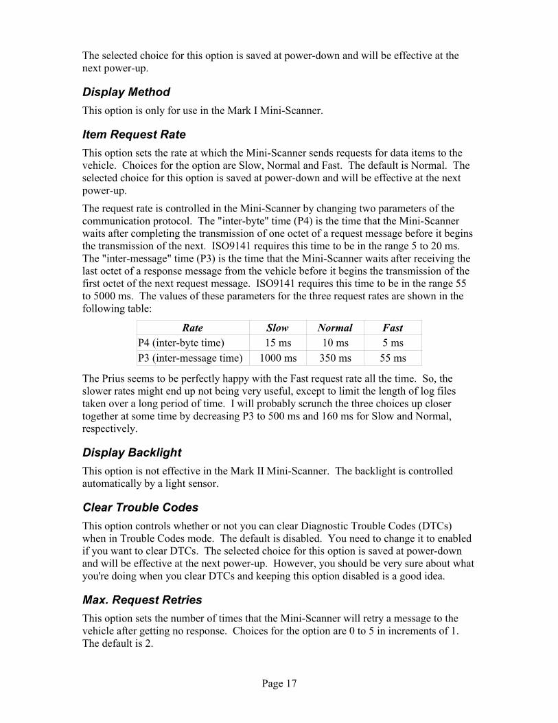
The request rate is controlled in the Mini-Scanner by changing two parameters of thecommunication protocol. The "inter-byte" time (P4) is the time that the Mini-Scannerwaits after completing the transmission of one octet of a request message before it beginsthe transmission of the next. ISO9141 requires this time to be in the range 5 to 20 ms.The "inter-message" time (P3) is the time that the Mini-Scanner waits after receiving thelast octet of a response message from the vehicle before it begins the transmission of thefirst octet of the next request message. ISO9141 requires this time to be in the range 55to 5000 ms. The values of these parameters for the three request rates are shown in thefollowing table:
Rate Slow Normal FastP4 (inter-byte time) 15 ms 10 ms 5 msP3 (inter-message time) 1000 ms 350 ms 55 ms
The Prius seems to be perfectly happy with the Fast request rate all the time. So, theslower rates might end up not being very useful, except to limit the length of log filestaken over a long period of time. I will probably scrunch the three choices up closertogether at some time by decreasing P3 to 500 ms and 160 ms for Slow and Normal,respectively.
Display BacklightThis option is not effective in the Mark II Mini-Scanner. The backlight is controlledautomatically by a light sensor.
Clear Trouble CodesThis option controls whether or not you can clear Diagnostic Trouble Codes (DTCs)when in Trouble Codes mode. The default is disabled. You need to change it to enabledif you want to clear DTCs. The selected choice for this option is saved at power-downand will be effective at the next power-up. However, you should be very sure about whatyou're doing when you clear DTCs and keeping this option disabled is a good idea.
Max. Request RetriesThis option sets the number of times that the Mini-Scanner will retry a message to thevehicle after getting no response. Choices for the option are 0 to 5 in increments of 1.The default is 2.
Page 17

The selected choice for this option is saved at power-down and will be effective at thenext power-up.
PowerOff Delay (sec)This option sets the length of time that the Mini-Scanner pauses after having decided toturn itself off before it actually powers off. This pause gives the user a chance to seewhat is happening and read displayed messages. Choices for the option are 2 to 7seconds in 1 second increments. The default is 5 seconds. The selected choice for thisoption is saved at power-down and will be effective at the next power-up. If the Mini-Scanner needs to save new settings (favorites or option choices), the power-down delaywill be increased by 50% to accommodate the additional message on the display.
Logging Data via the Serial PortThis chapter of the Prius Mini-Scanner User Manual describes the recording or “logging”of data using the serial port.
Data retrieved from the vehicle by the Mini-Scanner can be sent to a computer via theserial port. The data items sent are the same as those selected for display. However, onlynumerical data is sent, the descriptive text and units that you see on the display are notsent. You must remember what data was being displayed on each line when you examinethe data. This purely numerical data is very easy to import into a spreadsheet.
The format of the data is plain ASCII text. In other words the number 62.5 will be sent asthe four ASCII characters '6', '2', '.' and '5'.
The serial port operates at 9,600 bit/s, 8 data bits, no parity and one stop bit. These arethe same setting used by the Flash Loader, so if you have a terminal emulator set up forfirmware updates, you can use it to view the serial port data. Just connect the computerup and start the terminal emulator as if you were going to update the firmware (but don'thold down the escape key). Using the terminal emulator's capture features, you can savethe data to a file for later analysis or charting in a spreadsheet program.
TimestampEach data value is associated with a “timestamp”. This indicates the approximate time atwhich the data item was sampled and had that value. The timestamp is given in seconds.Timestamps start at zero when you turn on or reset the Mini-Scanner and do not representreal-world or “wall-clock” time. The long-term accuracy of the timestamps has not beenmeasured, but will be of the order of a second per hour.
The resolution of the timestamp is one millisecond, but this is not its short-term accuracy.Do not assume that the logged data samples are as precisely placed in time as thetimestamp resolution suggests. When the data is actually sampled by an ECU in thevehicle is not known. It could be sampled at some regular rate so that a request for thedata returns the most recent sample, whenever that was taken. Or, it is also possible thatthe sampling of data is triggered by the request on the OBD-II bus. But, exactly whenthis happens in relation to the request message and response is not know. The Mini-Scanner records the timestamp from an internal clock when the first octet of the vehicle'sresponse is received.
Page 18

Log FormatThe format in which timestamps and data are sent to the serial port is designed to belogged in a file and then imported into a spreadsheet. The data can then be analyzed andvisualized as a chart. The timestamps and data values are separated by tab characters, sowhen importing to a spreadsheet program, specify the file type as a tab-delimited text file.The format is best explained by an example:126.456 14.84126.927 14.0127.394 17.18 127.861 14.5128.329 19.53128.796 14.0129.263 19.92129.730 6.0130.197 20.31130.668 1.5131.135 19.92131.606 -4.0132.074 19.92132.540 -8.5Each line begins with a timestamp in the first column. Data values are placed in columnsafter the timestamp, separated from the timestamp by one or more tab characters. Thevalues of the data item selected for display in line one appear in the second column andare separated from the timestamp by a single tab. The values of the data item selected fordisplay in line two appear in the third column and are separated from the timestamp bytwo tabs. When you capture the serial port data to a file and import the file into aspreadsheet program, the timestamp, line one data and line two data will appear incolumns A, B and C, respectively.
As you pass 999.999 seconds (a little more than sixteen minutes) since the Mini-Scannerwas turned on or reset and the timestamp length steps up to eight digits, the data columnswill appear to jump one column to the right. This has no effect when the data is importedinto a spreadsheet.
If you select for display two data items that are retrieved from the same vehicle ECUusing the same parameter ID (PID), then each vehicle response updates both display lines.The effect on the serial port data is that twice as much data will appear and consecutivelines will have the same timestamp.
Creating a Chart in a SpreadsheetCreating a chart from data in this format imported into most spreadsheet programs is veryeasy. Simply select the block of data you want to chart, both rows and columns, andinstruct the program to make a chart from it. Specify the type of chart as X-Y or "scatter"so that the first column is used as X axis values. You may also be able to specify thatdata points are joined by a line, though some low-end spreadsheets mishandle the blankcells. By default, both data columns will be plotted against the same Y axis, so if theydiffer in scale (for example engine r.p.m. varying from 0 to 4000 and throttle varyingfrom 15 to 60) you will have some more work to do to plot each column against its ownY axis.
Page 19
Control of LoggingLogging can be controlled using the Right button when the Mini-Scanner is in Displaymode. Holding the right button toggles logging off and on. Logging is always on afterpowering up or resetting the Mini-Scanner. If you turn it off, this selection will not besaved and it will be on again after a power cycle or reset. The only reason you'd turn itoff would be if you have a computer connected and are capturing data and you want toreduce the file size by not logging during uninteresting driving periods.
So that you can find interesting events in a log file, you can drop a mark into the file bytapping the Right button. This happens even if logging is off, so you can drop the markand then turn logging on to keep the mark outside your data. The format of the mark is“Mk_n”, where n is the mark number. The mark number starts at zero for the first markafter power on or reset and increases by one for each mark you drop. Should you use 255marks, the next number will go back to zero. So that you know which mark number tolook for in the file, it is briefly shown on the display. You can write it down, togetherwith a description of the interesting driving event (but if you're driving, you should ofcourse have someone else write it down). Marking the log file can be more useful thanturning logging off and on because you can drop a mark after the interesting thinghappened, when it would be too late to turn logging on.
The above actions of the Right button are effective only in Display mode. In all othermodes, you have no control over logging.
Trouble Codes ModeTrouble Codes mode allows you to see any Diagnostic Trouble Codes (DTCs) that thecar's ECU have recorded. These indicate problems with the vehicle ranging from thetrivial (the fuel filler cap is lose) to the catastrophic (the engine won't start). If the checkengine light or “Malfunction Indicator Lamp” (MIL) comes on, it is very useful to findout why by retrieving DTCs. Sometimes you can fix the problem yourself but at the veryleast you can tell your service center something about the problem. You may be able todecide how urgent a trip to the shop might be.
To put the Mini-Scanner in Trouble Codes mode, tap the middle button until the displayregisters “Diag Trouble Codes”. From Display mode, this will be five taps.
Browsing ECUsWhen you enter Trouble Codes mode nothing much happens at first. By tapping theRight and Left buttons, you can browse forward and back in the list of ECUs with whichthe Mini-Scanner can communicate. These ECUs are:
• the Engine ECU, also known as the ECM (Engine Control Module), at address 1016
• the Hybrid Vehicle ECU, at address 1616
• the Battery ECU, at address D516
Data items are still being requested and logged. In order to retrieve DTCs from an ECU,select that ECU (by tapping the Right and Left buttons) and then hold the Right button.The result will appear on the display after a short pause. The requesting and logging ofdata items will stop. This is because the Mini-Scanner has to enter into a different modeof communication with the ECUs to retrieve the DTCs. If you accidentally enter Trouble
Page 20

Codes mode while logging, you will not miss any information as long as you don't holdeither the Right or Left buttons. You can just leave this mode by tapping or holding theMiddle button.
Once you have started the retrieval of DTCs by holding the Right button, the informationis refreshed at intervals of about one second. So, if a Trouble Code arises, you will see iton the display. If you tap the Right or Left buttons to select a different ECU, DTCs willthen be retrieved from that ECU and displayed. So, you can browse through the ECUsinspecting their DTCs in turn.
Interpreting DTCsThe display shows three DTCs, each consisting of a prefix letter and four digits. Thecode P0000 means that there is no Trouble Code, so when there are no DTCs in an ECUyou will see “P0000 P0000 P0000”. If you have one DTC, it will appear in the firstposition. For example, if you remove the Service Plug from the high voltage battery andturn the car on, the Hybrid Vehicle ECU will show “P3140 P0000 P0000”. The codeP3140 means "Interlock Malfunction" and can be looked up in the Diagnostic RepairManual. Much of the information from this manual is included in Appendix B - PriusDiagnostic Trouble Codes, below.
Leaving Trouble Codes ModeWhen you leave Trouble Codes mode (by tapping or holding the Middle button), if youstarted the retrieval of DTCs then the Mini-Scanner has to get back to the mode ofcommunication in which it can talk to all the ECUs and get data items. To do this, it willrepeat the ISO9141 slow initialization that it did when you turned it on. After a fewseconds, if you go back to Display mode, the display and logging of data items willresume. Changed settings have not been stored and the Display mode slots are as you leftthem. The slow initialization is purely to get back in touch with all the ECUs.
Peculiar QuirkExperimentally, I have found that if you return to Display mode while retrieving datafrom the Battery ECU, ISO9141 slow initialization may fail and the Mini-Scanner willthen turn itself off. This is probably a quirk of the vehicle and may not be present on allmodel years. If it is important to you that this not happen, go to the Hybrid Vehicle orEngine ECU before you leave trouble codes mode.
Clearing DTCsIn Trouble Codes mode it is possible to clear DTCs as well as display them. In general,this is not a good idea as your service department may need this information to diagnoseproblems with your car. Therefore, to clear DTCs, the Mini-Scanner makes you jumpthrough a few hoops. First, you must have Clearing Trouble Codes enabled in theOptions mode. Refer to the section on Options for how to do this. Now, select the ECUin which you want to clear DTCs by tapping the Right and Left buttons as before. Itdoesn't matter if you are retrieving DTCs or not, this will be started when you clear theDTCs. Hold the Left button. A message will appear asking you if you really want toclear the DTCs. (If Clearing Trouble Codes is not enabled in the Options mode, you willbe informed of this instead.) If you decide to continue and clear the DTCs, hold the Left
Page 21

button a second time. The DTCs will be cleared and the Mini-Scanner will retrieve theDTCs from that ECU, which naturally will all be P0000. If you change your mind aboutclearing DTCs, any button action other than holding the Left button will cancel therequest.
Updating Mini-Scanner FirmwareThe Prius Mini-Scanner contains a very small, highly integrated computer system called a“microcontroller”. The software program running on the microcontroller defines whatthe Mini-Scanner does. It looks to see if you've pressed a button, communicates with thecar and puts information on the display. A computer has many different programs storedon disk, one or more of which are loaded into memory on your command. By contrast, amicrocontroller has just one program fixed directly into memory that always runs whenthe system is turned on. For this reason, what you probably think of as software is giventhe slightly different name of “firmware”. It is firm, rather than soft, because it takes alittle more effort to change. (Hardware, of course, is hard because you're stuck with it.)Nevertheless, firmware can be changed with the right facilities and this chapter tells youhow to go about just that.
From time to time, ECROS Technology may release a new version of the Mini-Scannerfirmware. Just as with Microsoft® products, the purpose of this is to introduce new bugsand obscure essential functionality with unnecessary features. No, of course what I hopeto do is correct any problems that might arise and add more useful features. (I was justjoking, Bill, please don't sue me.) Unless you ask to be removed from mailing lists, youwill be notified of new firmware versions by e-mail. This will include a description ofwhat problems are fixed or new features added, so you can make up your mind whetheror not to update your Mini-Scanner. The actual firmware is posted on the Mini-ScannerWeb site and must be downloaded to a computer.
Downloading FirmwareAll released firmware for the Mini-Scanner, both Mark I and Mark II, is posted on theMini-Scanner Web site. As well as the most recent version, many earlier versions arealso available in case you want to go back to them. Brief notes list the major changes ateach version, but you might want to save the version announcement e-mails for detailedinformation if you think you will be bouncing between firmware versions.
The CD-ROM that comes with your Mini-Scanner contains the firmware installed on theMini-Scanner during manufacture and all earlier releases.
If you are familiar with downloading Zipped files from the Internet, you can skip the restof this section.
To download firmware, begin by browsing to the firmware page from the Mini-ScannerWeb site at http://miniscanner.ecrostech.com. There are separate pages for Mark I andMark II Mini-Scanners. Locate the version of the firmware you want to download. Donot click its link but instead use your browser's facility to save the link target on yourcomputer's disk. In Internet Exploder, right-click on the link and select Save Target As...from the pop-up menu. Browse to a suitable folder on your computer and save the file.
When the download is complete, locate the file and unZip it (that is, extract the contentsof the Zip archive). You can do this with WinZip, many other utilities or features built
Page 22

into recent versions of Microsoft Windows. What pops out of the archive is the firmwarefile or files you will use below to update the Mini-Scanner.
The Flash Loader The microcontroller in the Mini-Scanner stores its program in a type of memory called“Flash”. This is the same memory as is used in CompactFlash cards, FlashDrives, etc.The name, I think, originally suggested that you could change the contents of this memory“in a flash”, as compared to other technologies available when Flash was introduced. Asmall utility called a “Flash Loader” is built into the Mini-Scanner during manufacture.This runs before the Mini-Scanner program and normally does nothing but wait for afraction of a second before continuing. However, if you hook up a computer to the serialport and hold down a key, as described below, the Flash Loader takes control and themain program does not run. You can then use simple commands to remove the currentfirmware and install your new version.
The rest of this chapter describes in detail how to use the Flash Loader to update Mini-Scanner firmware.
Power to the Mini-ScannerTo update firmware, the Mini-Scanner must have a source of power. Normally, it gets itspower from the car via the DLC connector. This is perfectly fine for updating firmware,but it does mean that you have to take your computer, with the firmware file, to the car.If this is not convenient, you can remove the Mini-Scanner from the car, take it to yourcomputer and power it from a 9 volt smoke alarm battery.
Updating Firmware in the CarThe easiest way to update the firmware is to use a portable device such as a notebookcomputer. Make sure the new firmware file is stored on this computer, that it has a serial(“COM”) port and a terminal emulator program is available on it. It is best to run thecomputer from battery power. If you power it from the car using an adapter, make surethe output of the adapter is isolated from the car's electrical system. The Mini-Scanner is,of necessity, directly connected to the electrical ground of the car.
Using the 9 Volt Battery Hook-UpNot everyone has a notebook computer or other portable computing device. If you wantto take the Mini-Scanner to a computer to perform a firmware update, special provisionhas been made for this. Follow the uninstallation instructions to remove the main unitfrom the car. You will need the 9 volt battery hookup that was included in your Mini-Scanner package and a fairly fresh 9 volt alkaline smoke alarm battery or a well chargednickel metal hydride battery of the same size.
Page 23

As you have left the adapter cable in the car, theheader to which this cable connects will be open.The battery connects to the left-most two pins ofthis header. The photograph at right shows the 9volt battery hookup connected to a Mini-Scannerand to a battery. The red wire goes to the pin in thetop row, closer to the buttons, but the connectorwill not fit the other way round so it should not bepossible to get this wrong. Additional photographsof higher resolution are included on the CD-ROM.
If the display backlight is on, the current drawn bythe Mini-Scanner is higher than is normal for abattery of this type. It is best, therefore, to work ina well lighted room so that the backlight remains off.
Connecting the Serial CableThe Mini-Scanner serial cable consists of a telephone cord and an adapter. Plug eitherend of the telephone cord into the adapter and plug the adapter into the COM port of yourcomputer. Plug the other end of the telephone cord into the jack on the right hand side ofthe Mini-Scanner main unit.
Remember that although the Mini-Scanner uses telephone-type connectors and cords, youshould never connect it to a telephone circuit or it will be damaged.
Note for Mark I owners (skip this sidebar if you have a Mark II): The Mark I Mini-Scanner does nothave the externally accessible RJ11 jack for the serial cable. Instead, the case must be opened andthe cable attached inside, much like the adapter cable. For details, refer to the Mark I Web site.
If you are using an extension serial cable for extra reach, you should make sure you havethe right type of extension. If you are planning to power your computer from the car,look out for grounding problems. <<To do – expand and clarify>>
Terminal Emulator ProgramsThe computer or other device you use to update firmware must be able to run a kind ofprogram called a “terminal emulator”. This allows the computer to act as a “terminal”.Whatever you type on the keyboard is transmitted to some other device that you haveconnected to and anything that device sends back is displayed on the screen. Above, wehave connected to the Mini-Scanner using the serial (“COM”) port, but typically terminalemulators will also work with other connections such as the Internet.
The Microsoft® Windows™ operating system includes a terminal emulator programcalled HyperTerminal. The Prius Mini-Scanner Welcome CD-ROM includes a freewareterminal emulator called TeraTerm Pro. ECROS Technology recommends that you useTeraTerm Pro. Not only is it easier to use but it completes the update in a quarter of thetime as compared to HyperTerminal. Other terminal emulators are available for theWindows, Linux and Mac operating systems and will all work for firmware updates.
HyperTerminalVersions of Microsoft® Windows™ since about Windows 95 have included a Terminal
Page 24
Photo 10 – 9 Volt Battery Connection

Emulator called “HyperTerminal”. On Windows XP, you can find it at Start → Programs→ Accessories → Communications → HyperTerminal. In other versions it may be in differentplaces; consult the Windows documentation for details (OK, realistically just look arounduntil you find it). I will now try to tell you how to use HyperTerminal, although franklyI'd rather you not use it because it is an appallingly badly designed piece of software.
Start HyperTerminal (from the Start button, depending on where it is on your version ofWindows™). The Connection Description dialog will appear. Click Cancel to get rid ofit. Now you just have the HyperTerminal main window.
Select File → Properties on the menu to bring up the New Connection Properties dialog.On the Connect To tab of this dialog, bring down the Connect using: pick list and selectCOM1 or COM2, etc., according to which serial port you are using on your computer. Then,click the Configure... button to bring up the COMn Properties dialog. Set the five pick listsas follows: Bits per second: to 9600, Data bits: to 8, Parity: to None, Stop bits: to 1 and Flowcontrol: to None. Click the OK button to accept these new settings and get rid of thisdialog. Now go to the Settings tab of the New Connection Properties dialog, whichshould still be on the screen. Bring down the Emulation pick list and select TTY. Click theASCII Setup... button and the ASCII Setup dialog appears. Check the Send line ends withline feeds checkbox. Click the OK button to finish this dialog. Everything else can be leftat its default value. Click the OK button to finish up configuration. You should onceagain be back to the main window.
Select File → Save As... on the menu to bring back the Connection Description dialog. Inthe Name edit box, type a suitable name that will allow you to remember what this“connection” is for. For example, you might type “Mini-Scanner Update”. If you wish, youcan choose an icon from those presented. I rather like the one with the picture of anatom. Click the OK button, whereupon the dialog will disappear and be replaced with theSave As... browser dialog. HyperTerminal is offering to save a file describing theconnection in a place of its choosing on your computer. The filename is already filled infrom what you entered in the previous dialog. Accept this filename and location byclicking Save. Again, you are back at the main window.
Now, exit HyperTerminal. It sounds silly, but do it. You can use File → Exit or click theClose button (the one at top-right with a cross in it). Don't try to use HyperTerminal tocommunicate with the Mini-Scanner at this point.
Go back to start HyperTerminal again, but now as you reach the end of your explorationof the Start menu you will see two “HyperTerminal”s. The new one is a folder, (whichyou can tell from the icon and the arrow pointing to another menu level). Continue to thismenu level and you should find the connection you just set up under the name you gaveit. Select this, and HyperTerminal will start up with all the configuration already done.
At this point, you have completed the configuration mentioned in step 3 of FirmwareUpdate Procedure, below. In future, at step 3, just start HyperTerminal using your pre-configured connection as described.
In step 6 of Firmware Update Procedure, you will need to send the firmware file to theMini-Scanner Flash Loader. To do this, select Transfer → Send Text File... on the menu tobring up the Send Text File file browser dialog. Using this browser, locate the firmwarefile on your computer, click on it to select it and then click the Open button. The dialogwill close and the file transfer will begin. You should see dots begin to appear in themain HyperTerminal window as each record passes from the file to the Mini-Scanner and
Page 25

is acknowledged as correct. Do not touch the keyboard until the file upload is completeand the Flash Loader presents you with a new prompt. The upload will take severalminutes.
TeraTerm ProThe terminal emulator program TeraTerm Pro is included with the Mini-Scanner on thePrius Mini-Scanner Welcome CD-ROM. It is freeware, which means that you can use itwithout registering or paying any money to anyone. About the only thing you can't dowith it is redistribute modified versions. Unfortunately, this is exactly what I've done asI've pre-configured the program for the Mini-Scanner. I hope that the program's authordoes not consider changing the default settings to be “modification”.
TeraTerm Pro consists of a couple of dozen files which are in the TeraTermPro folder ofthe CD-ROM. You can run the terminal emulator from the CD-ROM by double-clickingthe file ttermpro.exe. It is probably better, however, to install it on your computer. To dothis, just create a new folder somewhere of your choosing and copy to it all the files in theTeraTermPro folder on the CD-ROM. For example, you might decide to install TeraTermPro in C:\Program Files\TeraTermPro. You can run the program by double-clicking the filettermpro.exe in this new folder or you can create a shortcut in the Start menu or on thedesktop. Consult your operating system documentation for details.
There is a configuration change that you must make only if you are not using the COM1port of your computer. Select Setup → Serial port... on the menu to bring up the TeraTermSerial Port Setup dialog. In the Port: pick list, select COM2 or COM3, etc. according towhich serial port you are using. Click OK. To save this change so that you don't have tomake it every time, select Setup → Save setup... on the menu to bring up the TeraTermSave Setup dialog. Browse to the directory into which you copied the TeraTerm Pro filesand slick Save. This will overwrite the original configuration and in future when you startTeraTerm Pro it will use the serial port you selected.
In step 6 of Firmware Update Procedure, you will need to send the firmware file to theMini-Scanner Flash Loader. To do this, select File → Send File... on the menu to bring upthe TeraTerm: Send File file browser dialog. Using this browser, locate the firmware fileon your computer, click on it to select it and then click the Open button. The browserdialog will close, a different TeraTerm: Send File dialog will open and the file transferwill begin. You should see dots begin to appear in the main TeraTerm Pro window aseach record passes from the file to the Mini-Scanner and is acknowledged as correct. Itwill probably be necessary to move the dialog out of the way to see this. Do not touch thekeyboard or click the dialog buttons until the file upload is complete and the Flash Loaderpresents you with a new prompt. The upload will take a minute or so.
Other Terminal EmulatorsYou can update the Mini-Scanner firmware using any terminal emulator program that cansend a file in plain text format. Configure the serial port for 9,600 bit/s, 8 data bits, 1stop bit and no parity. Disable flow control. Make sure you select the COM port towhich the Mini-Scanner is connected.
Note for Mark I owners (skip this sidebar if you have a Mark II): The Mark I Mini-Scanner has anearlier version of the Flash Loader than the Mark II and an additional configuration step is needed.Set the terminal emulator so that line ends are transmitted as both a carriage return and a line feed.
Page 26

When you send the firmware file to the Mini-Scanner Flash Loader in step 6 of FirmwareUpdate Procedure, make sure you send it as plain text. Do not use a file transfer protocolsuch as kermit or xmodem.
Firmware Update ProcedureTo perform a firmware update, follow the numbered steps below. In all cases of pressingor holding down a key, it is a key on the computer keyboard to which I am referring.When I say “you will see”, I mean on the computer screen. You are basically interactingwith the computer and terminal emulator program from steps 3 to 7 and need not touch orlook at the Mini-Scanner except to press the On/Reset button in step 4.
1. Make sure the Mini-Scanner has power. If you are in the car and the DLC adapter andcable are connected normally, this is already done. There is no need to turn the car on.If you have removed the Mini-Scanner from the car, use a 9 volt battery as described inUsing the 9 Volt Battery Hook-Up, above.
2. Connect the serial cable to the Mini-Scanner and to a serial (“COM”) port on yourcomputer (see Connecting the Serial Cable, above, for details).
3. Turn on the computer and run the terminal emulator application. If you have notalready done this, set it to connect via the COM port to which you connected the Mini-Scanner in step 2 and configure the serial port for 9600 bit/s, eight data bits, no parity,one stop bit and no flow control as described in Terminal Emulator Programs, above.
4. Hold down the escape (Esc) key (see note, below), wait a second or two and, whilecontinuing to hold down the escape key, press and release the On/Reset button of theMini-Scanner. This will get you into the Flash Loader and you will see a bannermessage and then a prompt (">").
5. To erase the existing firmware in the Mini-Scanner, press 'z'. You will see themessage “erasing” and after a few seconds a new prompt.
Note for Mark I owners (skip this if you have a Mark II as it happens automatically): Put the FlashLoader in “program” mode by pressing “p”. You will see the message “prgm” and a new prompt.
6. Using the terminal emulator application, send the new firmware file to the Mini-Scanner in plain ASCII text format. As each record in the file is read, you will see adot appear. It may take several minutes to complete the update. Do not interrupt theupdate by resetting the Mini-Scanner, unplugging the cable or quitting the terminalemulator application. When it is finished, a new prompt will appear.
7. Press “q” to quit the Flash Loader (the “q” will not be echoed). The Mini-Scanner willimmediately run the new firmware. (Of course if you are not in a car, or the car is notturned on, the Mini-Scanner will not get a vehicle response and so it will turn itselfoff. Either now or later, re-install the Mini-Scanner in the car or turn the car on andthen press the On/Reset button to start the new firmware.)
8. Disconnect the serial cable (if desired).
That's all there is to it. The rest of this chapter discusses problems that might occur andhow to solve them and advanced and expert use of the Flash Loader. In most cases, ifyou are not experiencing problems, you can skip the remaining material.
Page 27

Problems and ErrorsThis section attempts to identify some problems that might occur with firmware updatesand tells you how to go about solving them. The Flash Loader includes diagnostics todetect bad firmware files and hardware problems in the Mini-Scanner and the errors itissues are listed and explained here. If you are using a 9 volt battery and experience anyproblems, make sure the battery is not the problem. It does not have to be new, but itshould not be on the last half of its life. Try a new battery if you have one.
Nothing Happens When I Reset the Mini-ScannerIf, when you release the On/Reset button in step 4, you see nothing at all in the terminalemulator window and the Mini-Scanner starts normally, check the following:
• Make sure the COM port of your computer is working. In many computers, the COMports can be disabled in the BIOS.
• Check that you have configured the terminal emulator to use the COM port into whichyou have plugged the Mini-Scanner serial cable.
• Check all other configuration settings of the terminal emulator. You should be using9,600 bit/s, 8 data bits, no parity and 1 stop bit. Flow control should be disabled.
• Make sure the plugs on the telephone cable are fully seated into the jacks in the Mini-Scanner and serial port adapter. They will click when they are all the way in.
• If you have a Mini-Scanner Mark I, make sure the 10-pin connector is properly seatedover all ten pins of the serial port header inside the main unit.
• If you have a Mini-Scanner with a debug port and have used it to replace the firmware,you will have erased the Flash Loader. You will need to put it back before you can useit again. A ZiLOG ZDS II project to accomplish this was e-mailed to you at about thetime you received your Mini-Scanner.
• Check the items in the next section also.
I Get a Short Burst of GarbageIf, when you release the On/Reset button in step 4, you get something in the terminalemulator window but it consists of punctuation and other garbage characters, check thefollowing:
• Check the serial port configuration settings of the terminal emulator. You should beusing 9,600 bit/s, 8 data bits, no parity and 1 stop bit.
• If you are using a telephone cord other than the one supplied with the Mini-ScannerMark II, make sure it is of the “cross-over” kind. If you hold up the little clear plasticplugs, turn them the same way round and peer inside, you should see the colored wiresarranged in the opposite order at each end.
• If you are using a serial cable extension, make sure it is of the “straight-through” kindand not a “null-modem” cable. Try without the extension.
I Get a Row of DotsIf, when you release the On/Reset button in step 4, you get a row of dots in the terminal
Page 28

emulator window and the Mini-Scanner starts up normally, the serial port and terminalemulator are correctly set up. However, the Flash Loader is not detecting the escapecharacter you are trying to send it. It pauses only briefly during startup to look for thischaracter. The reason that step 4 tells you to hold down the escape key is to activate theauto-repeat of your computer keyboard. This sends many escape characters quite quicklyso that one is noticed by the Flash Loader before it gives up and starts the Mini-Scannermain program. If sometimes you get to the Flash Loader banner/prompt and sometimesyou don't, there is nothing wrong with trying repeatedly until you get in. If you cannotactivate the Flash Loader at all, check the following:
• Make sure that you still have the escape key held down when you release the On/Resetbutton of the Mini-Scanner.
• Make sure that before you release the On/Reset button, you have held the escape keydown long enough to start the auto-repeat feature of your keyboard. Check the repeatdelay setting of the keyboard in the Windows Control Panel.
• Check the keyboard repeat rate in the Windows Control Panel. If it is set too low, theFlash Loader might begin and end looking for an escape in between repeats. Tryincreasing the repeat rate.
• There may be a break between the computer's TXD (transmit data) pin and the Mini-Scanner's RXD (receive data) pin. Look for damage to the cables, dirty or bentcontacts, etc.
I Don't Get Dots in Step 6Very important note for Mark I owners (skip this section if you have a Mark II): About half of Mark Iowners hit the problem described here. They were people who knew how to set up HyperTerminaland therefore did not follow the instructions. If you are reading this before performing a firmwareupdate, please set up HyperTerminal exactly as described or, even better, use TeraTerm Pro. In theMark II, the Flash Loader has been improved so that the problem cannot occur.
If you get to the Flash Loader banner and everything seems to be working but when you send thefirmware file to the Mini-Scanner in step 7 you don't get dots as each record is processed, yourterminal emulator program may be suppressing line feed characters. To test this, start again. You'llhave to stop the file transfer or quit the terminal emulator program. Once you have the terminalemulator going again, try pressing the escape key to get back to the Flash Loader prompt. If this doesnot work, you will have to reset the Mini-Scanner again. Once at the prompt, hit the Enter keyseveral times. If the mode announcement and prompt appear each time, see “I Still Don't Get Dots”,below. If nothing happens, the line feeds are not getting through. Explore the settings of yourterminal emulator looking for line end processing options. Choose line feed or both carriage returnand line feed. Carriage return on its own will not work. Instructions for setting up HyperTerminalcorrectly are included in Terminal Emulator Programs, above. TeraTerm Pro is supplied alreadyproperly configured.
I Just Don't Get Those DotsIf you have a Mark II Mini-Scanner or your terminal emulator is set up to pass line feeds(that is, when you hit the Enter key you get the mode announcement and prompt) and youdon't get dots in Step 6, the next thing to check is that the Mini-Scanner is listening forIntel Hex records. Go to verify mode and at the computer keyboard, type the following,(remember the final Enter):
:0000000000 (colon and ten zeros then Enter)
Page 29
:00000001FF (colon, seven zeros, a one, two Fs then Enter)
After the first line, you should get a dot. After the second line, you should be back at theidle prompt. If this test does not work, the Mini-Scanner is probably at fault and mayrequire repair. If it does work, the problem is with the file you're trying to load or theterminal emulator's file send function. Make sure you're using the right firmware file,that it has been un-zipped (the file extension should be .hex) and that the file contains lotsof separate lines of numbers, some lines quite long, all starting with a colon character.
Get back the attention of the Flash Loader by starting again at step 4 or hitting Escape andEnter so that the prompt reappears. Make sure your terminal emulator application isworking properly. If you turn on its “local echo” option, you will see the file being sent,but this will obscure the responses of the Flash Loader somewhat. The last line of datasent from the file should look something like this: :00000001FF.
Windows NT and HyperTerminal have been reported to malfunction in the way we'renow discussing. The only known solution is to forget HyperTerminal and get a decentterminal emulator such as TeraTerm Pro.
I Get Some Dots, Then They StopInspect the firmware file to make sure it's all there. If somehow part of the file has beenchopped off, the firmware update will just stop in the middle. Look at the last line of thefile in a text editor such as Notepad. It should be the end-of-file record, which lookssomething like this: :00000001FF. The 01 in the eighth and ninth positions are the end-of-file record type and must be correct although other characters may be different. If thefile is corrupt, you will need to get another one. Another possibility is that the file sendoperation was terminated somehow. If the terminal emulator program allows you to aborta transfer, did you accidentally do this?
I don't want to beat this point to death, but if you're using a 9 V battery you did make sureit's not on its last gasp, didn't you? It hasn't just died, has it?
New Program Does Not RunIf, after successfully following the basic update procedure, you get the message “no userprogram!” when you type “q”, the update did not take place. Look for error messagesduring the file upload. Note that if all is well, then the “q” is not echoed. The Mini-Scanner just starts right up.
Note for Mark I owners (skip this if you have a Mark II): If there are only dots (no errors) during thefile upload, a possible cause is that you did not type “p” to put the Flash Loader into program mode.
Lots of “5” or “Error 7” MessagesThis error means that you are attempting to overwrite data that is already in the Mini-Scanner. A possible cause is that you missed out step 5 in the update procedure (erasingthe current firmware).
Flash Loader ErrorsThis section explains error messages you might see from the Flash Loader if somethinggoes wrong. If you follow the update procedure carefully and use an unZipped firmwarefile obtained from ECROS Technology, you are very, very unlikely to ever see an error.
Page 30
Note for Mark I owners: whereas the Mark II prints just a number, such as “1”, in place of the dotwhen an error occurs, the Mark I prints something like “error 4”. The error numbers in the Mark Iwere in no particular order but for the Mark II were rearranged to give an indication of how severethe problem is. In summary, but format and number differ. In the error descriptions, the Mark I errormessage is shown in brackets, e.g. [Mark I: error 4], after the Mark II error number, e.g. 1.
no user program! - The Mini-Scanner does not contain a user program. Repeat theupdate procedure.
1 [Mark I: error 4] - A mismatch was detected during a verify operation. This error isissued for each record containing data that does not match the current Mini-Scannerfirmware. The Mini-Scanner does not contain the same firmware as the selected file.
2 [Mark I: error 2] - A record in the input file had a bad checksum. The file is not in thecorrect format or is corrupt. Obtain a new firmware file. Note that an Intel Hex32 file islikely to cause this error. The Flash Loader only reads Intel Hex16 files.
3 [Mark I: error 3] - A record in the input file had a bad value in the record type field.The file is not an Intel Hex file, is not in the correct format or is corrupt. Obtain a newfirmware file. Note that an Intel Hex32 file is likely to cause this error. The Flash Loaderonly reads Intel Hex16 files.
4 [Mark I: error 1] - A record in the input file contained a character that is not ahexadecimal digit. The file is not an Intel Hex file, is not in the correct format or iscorrupt. Obtain a new firmware file.
5 [Mark I: error 7] - Data from the firmware file cannot be programmed because it is atan address in the Mini-Scanner memory that is not empty and does not already containthat data. If you are performing a full update of the firmware, start again and be sure toerase the old firmware first. If this error recurs, return the Mini-Scanner for repair.
6 [Mark I: error 5] - The microcontroller was unable to unlock its programminghardware. Return the Mini-Scanner for repair.
7 [Mark I: error 8] - The microcontroller failed to write the new firmware into itsmemory. Return the Mini-Scanner for repair.
8 [Mark I: error 6 or 9] - The firmware file contains data to be written to an addressreserved by the Flash Loader for its own use. It has been constructed without properregard for the rules that allow it to work with the Flash Loader. Obtain a new firmwarefile.
The difference between errors 6 and 9 in the Mark I are subtle and not helpful to the user.
9 [Mark I: error 0A] - You aborted a download by pressing the escape key.
Advanced Use of the Flash LoaderIn addition to updating firmware, you can use the Flash Loader to verify that the firmwarein the Mini-Scanner corresponds to a particular file. This is useful to make absolutelysure that an update worked and also to find out what firmware you are running if you losetrack. Follow the basic procedure, but in step 5 don't erase the firmware and instead, type'v' for verify. You will see the message “vrfy” and a new prompt. When you send the fileusing the terminal emulator, dots should appear just as before. If there is a differencebetween the file and what is in the Mini-Scanner, the message “1” (or, for the Mark I,
Page 31

“error 4”) will appear instead of a dot for each record of the file in which there is amismatch.
To perform a verify operation immediately after a new upload, repeat step 6 beforeproceeding to step 7. The Mark II Flash Loader is automatically in verify mode after theupload, but Mark I owners must type 'v'.
If a firmware update is interrupted, for example by accidentally resetting the Mini-Scanner or a computer crash, it should be sufficient to simply start again. Try to be sureto get into the Flash Loader on your first reset attempt (step 4) as otherwise you will runthe part of the user program that was loaded. There is a very, very small chance that thiscould be harmful to the Mini-Scanner or Flash Loader program.
Expert Use of the Flash LoaderThe Flash Loader has three modes of operation, test, program and verify. This controlswhat happens to the data read from an input file. A mode announcement message, “test”,“prgm” or “vrfy”, appears each time the prompt is issued to tell you what mode you arein. If you hit the enter key, the prompt is repeated, including the mode message. Otherinput is not echoed so nothing will happen unless you hit a valid command key.
On activating the Flash Loader from system reset, it is in test mode. Typing “p” puts youin program mode, typing “v” puts you in verify mode and typing “t” puts you in testmode. You can switch between these modes at any time. An erase operation puts theFlash Loader into program mode. After reading in an Intel Hex16 file and detecting theend-of-file record, the Flash Loader changes to verify mode.
Note for Mark I owners (skip this if you have a Mark II): the Flash Loader in the Mark I indicates testmode with the message “idle”, although it still functions as described above. Modes are not changedautomatically and you have to type “p” to go to program mode and “v” to got to verify mode. Thereis no command to return to test mode, other than restarting the Flash Loader.
If you send a file to the Flash Loader when it is in idle mode, the basic syntax of the file ischecked but nothing is programmed or verified. The safest way to check an unknown fileis to upload it in idle mode. If you get nothing but dots, the file is in Intel Hex16 formatand should be safe to program into the Mini-Scanner.
You can upload and program a new file to the Mini-Scanner without erasing the existingprogram. This will work if either the new program file is a strict superset of the existingone or if the two files are disjoint. In the first case, the Flash Loader will simply ignoreall the bytes in the new file that have already been programmed in the same place by aprevious upload. In the second case, all locations programmed by the second file are stillin the unprogrammed state from a previous erasure. This way of using the Flash Loadercould be useful to add data to tables in the firmware in which space has been reserved forthis purpose.
Summary of Button FunctionsThe following table summarizes the functions of the Left and Right buttons in the variousmodes in which the Mini-Scanner operates:
Page 32

Left ButtonHold Tap
ModeRight Button
Tap Hold(none) (none) Display Mark Log Toggle Logging
Copy to Display Previous Slot Favorites Next Slot Set from Display(none) Previous Item Select Line 1 Next Item (none)(none) Previous Item Select Line 2 Next Item (none)
Make Choice Next Option Options Next Choice Default ChoiceClear DTCs Previous ECU Trouble Codes Next ECU Get DTCs
To move from one mode to the next, tap the Middle button. To return from any mode toDisplay mode, hold the Middle button.
To turn off the Mini-Scanner without turning off the car, press the Left, Middle and Rightbuttons at the same time.
On the Mark I Mini-Scanner only, to have the display backlight come on when you turnon or reset the unit, hold the left button down until you have released the On/Resetbutton.
Appendix A - Available Data ItemsThis appendix presents a listing of the data items that you can display with the PriusMini-Scanner. For methods of selecting which items to display, see above. Any itemsthat appear to be available for display but are not described here are unsupported, whichmeans I probably haven't figured out what they are yet.
The “||`|” symbols are placeholders for the actual values. You will see them when a dataitem is first selected to a display line, but they will then be overwritten with the actualitem value retrieved from the vehicle. For example, “Battery SoC: ||`| %” will be replacedwith something like “Battery SoC: 57.5 %” when the vehicle responds to a request for thevalue of the SoC.
Listing of Data ItemsThe order in which items are listed here corresponds to the order in which they appear inthe Mini-Scanner's Select Line modes. I have tried to keep the more interesting itemsearly in the list and also at the very end (since you can go backwards around the list).Until the list stabilizes, a new release may mess up your favorite selections, so you mightwant to keep a written record of your favorites and check them after uploading newfirmware.
Main Battery State-of-Charge (SoC)Main (traction) battery state of charge (SoC), in percent. Experiments suggest that thispercentage is referenced to the full rated capacity of the battery, which is 6.5ampere.hours.
You can use the SoC value to estimate how “willing”the car will be to run on batterypower only. For example, at 60% or higher, you can draw up to about 30 amps from thebattery before the engine starts up. At lower SoC, the current at which the engine starts is
Page 33
Battery SoC: ||`| %

reduced.
Correlating the indicated SoC with the battery icon on the Energy Monitor display resultsin some surprises. The table below shows the SoC points at which the icon changes statein the charging and discharging directions. These were determined by independentexperiments on US and UK Prius. The EMPTY icon was not seen down to 22% SoC.The maximum SoC achieved was 80%.
Charging (Rising SoC) Discharging (Falling SoC)SoC Battery Icon SoC Battery Icon
74.5% → 75% 3/4 → FULL 72% → 71.5% FULL → 3/457.5% → 58% 1/2 → 3/4 55% → 54.5% 3/4 → 1/244.5% → 45% 1/4 → 1/2 42% → 41.5% 1/2 → 1/4(not known) EMPTY → 1/4 (below 22%) 1/4 → EMPTY
Two things immediately stand out:
The range of SoC represented by each icon state is not uniform. The 3/4 icon covers anSoC range of 17% but the 1/2 state covers only 13%. The 1/4 icon appears to cover 20%or more and the FULL icon less than 10% if the maximum possible SoC is indeed 80%.
There is a hysteresis of 3% between icon state changes in the charging and dischargingdirections. As a result, the 3/4 icon can be displayed for SoCs in the range 55% to 74.5%.If the car is not driven at low speed for many miles the SoC will not fall below 55% so itis no wonder that some people report that their battery icon never changes.
The battery icon should therefore be interpreted only as a very rough measure of batterySoC.
Main Battery Charge CurrentMain (traction) battery current, in amperes. The displayed value is positive for charge(current into the battery) and negative for discharge (current out of the battery). You canuse this value in conjunction with the battery state of charge to influence whether the carruns on battery power only or starts the engine. In city driving, especially with smallhills, you can obtain a noticeable improvement in fuel economy by extending periods ofbattery only driving and using the engine in a “pulsed” fashion to accelerate and climbhills. You can also use this value to learn a braking strategy that avoids the use of thefriction brakes and therefore maximizes the energy recovered by regenerative braking.
Vehicle SpeedVehicle speed, in kilometers per hour. The Toyota Repair Manual Volume 1(Diagnostics) says that when the vehicle is stopped the value should be 0 km/hr. Howmuch does that manual cost, again?
Vehicle Speed in Miles per HourVehicle speed, in miles per hour. Since the ECUs respond to a request for vehicle speedin kilometers per hour, this number is computed by dividing the result by 1.6. Thisshould be accurate enough for Europeans to know by how much they're exceeding thespeed limit in the United Kingdom. However, if you're recording speed via the serial port
Page 34
Speed: |||`| m.p.h.
Speed: ||| km/hr
Current: -||`|| A

to perform some off-line calculations, it is better to obtain the speed in kilometers perhour and compute the figure in miles per hour yourself, if necessary.
Engine Spin Rate (Tachometer)Engine spin rate, in revolutions per minute.
Throttle PositionThrottle position sensor output, in percent. Note that the throttle we're talking about hereis not the pedal under your right foot, which is the accelerator pedal, but the valve thatrestricts the flow of air into the engine inlet manifold. The Toyota Repair ManualVolume 1 (Diagnostics) describes this item as “Voltage Output of Throttle PositionSensor Calculated as a percentage”. It goes on to say that 0V corresponds to 0% and 5Vto 100%. When the throttle is fully closed we should see 0 - 5% and when the throttle isfully open, 90 - 100%. This makes me suspect that I am not scaling the data properly.With my scaling, the rest position of the throttle sensor seems to be at about 15%. Iobtained this scaling from Alex Peper's scan tool, which I assume follows the standard forOBD II mandated items such as this one.
Calculated Engine LoadCalculated load, in percent. This is a standard OBD-II data item. The Toyota RepairManual Volume 1 (Diagnostics) describes this as “Calculator Load”, but explains that itis the “Current intake air volume as a proportion of max. intake air volume”. This makesa lot of sense if you substitute “mass flow rate” for “volume”. The manual goes on to saythat when idling you can expect a value of 5.4 - 19.2% and when “Racing without load(2,250 rpm)” you should expect 6.9 - 16.2%.
Engine Coolant TemperatureEngine coolant temperature, in degrees Celsius. With city driving in hot weather, myengine temperature rises to 89 °C, which I presume is the point at which the thermostatopens. The Toyota Repair Manual Volume 1 (Diagnostics) describes this as “Enginecoolant Temp. Sensor Value” and goes on to say that after warming up you should expectvalues in the range 80 - 95°C (176 -203°F).
The blue “cold engine” light goes out when the engine coolant temperature reaches about50 °C. The car will not stop the engine and run on battery power until the temperaturereaches about 71 °C. However, once this has happened, the engine can cool to about 59 °C before the car insists on running the engine again.
Ignition (Spark) AdvanceCylinder one spark timing advance, in degrees of crankshaft rotation. It is veryinteresting to watch this during the first minute after you start the car. It goes negative,representing a timing retard. The fuel/air mixture is being ignited as the piston descends.Very little energy is extracted, which is why the car runs on battery power at this time(watch the battery current also). So, the exhaust gas remains very hot and quickly heatsup the oxygen sensors and catalytic converter to gain control over emissions. The ToyotaRepair Manual Volume 1 (Diagnostics) describes this as “Ignition Timing of CylinderNo. 1” and goes on to say that when idling you should expect to see values of “BTDC 7
Page 35
Calc. Load: ||`|| %
Throttle: ||`|| %
Engine: ||||`|| rpm
Spark Advnce: ||`| °
Engn. Coolant:||| °C

-15 deg.”
Temperature of Air Entering EngineTemperature of air flowing into the engine intake manifold, in degrees Celsius. Thetemperature sensor for this data item is built into the mass air flow sensor (see below). Itis not the sensor behind the front bumper that measures ambient air temperature fordisplay on the Multi-Function Display.
Rate of Air Flow into EngineRate of air flow into the engine intake manifold, in grammes per second. Since theemissions control system keeps the fuel to air ratio fairly constant at all times, this airflow is a strong indicator of fuel flow as well. Except, that is, when the engine isspinning without fuel or spark.
MG2 Spin RateMG2 spin rate, in revolutions per minute. Since MG2 is connected to the front wheels ofthe vehicle via a fixed gear train, there is a simple fixed relationship between the spin rateof MG2 and the vehicle speed. Depending on the rolling radius of your tires, you will seeabout 58 to 60 r.p.m. at MG2 for each one m.p.h. of vehicle speed. Assuming standardUS tires (Potenzas) and nominal inflation for an effective rolling radius of 11.1 inches,the exact ratio from MG2 spin rate to vehicle speed is 6000 (r.p.m.) to 163.27 (km.hr).Although speed always has a positive value, the spin rate of MG2 shows negative whenthe vehicle moves backwards.
MG2 TorqueMG2 torque in newton.metres. This needs to be verified, or at least checked. I guessedthe scaling of the data by blocking the wheels of my car and watching this figure (scaled)climb to just over 200 before the car surged up onto the blocks. Maybe someone couldcreep up a hill of known slope on battery power at constant speed. In fact, I'm nowstarting to think that the scaling factor is wrong and the Mini-Scanner reads torque low by20%. For example, when it shows 100 N.m, the torque is really 125 N.m.
Note that generally when a motor/generator's spin and torque are in the same direction, itis acting as a motor. When they are in opposite directions, i.e. one is positive and theother negative, it is acting as a generator. The only time that the foregoing is not true isduring brief transition periods, for example when the direction of spin is being changedby the application of power.
MG1 Spin RateMG1 spin rate, in revolutions per minute. This is an interesting figure to watch whenyou're interested in how the Prius manages without having gears to shift. The faster MG1spins forwards, the faster the engine can spin for a give vehicle speed and the moreelectrical power can be passed to MG2 to increase the total driving torque. This is howthe car simulates a lower mechanical gear. By reducing MG1's spin rate, the vehiclespeed increases in relation to the engine spin rate, but less electrical power is available topass to MG2. This is how the car simulates moving to higher mechanical gears. Whenthe car is up to speed and power demand is low, you will see MG1 reverse direction.
Page 36
Int. Air Temp: || °C
Air Flow: ||`|| gm/s
MG2 Torq: |||`| N.m
MG1 Spin: |||| rpm
MG2 Spin: |||| rpm
Now it is actually taking up power, acting as a motor to increase the vehicle speedrelative to the engine spin, putting the car in what amounts to overdrive. This powercomes from MG2, which contrary to expectations, now acts as a generator, actuallyholding the car back. Take a look at MG2 torque while you are cruising and you'll see anegative value.
MG1 TorqueMG1 torque in newton.metres. This needs to be verified, or at least checked. I guessedthe scaling of the data by observing a (scaled) figure of -8 when MG1 was spinning at4700 r.p.m. and charging the battery at 13 amps with the car stationary. Both mechanicaland electrical powers work out to be a bit less than 4 kW. Again, I'm starting to think thatthe current scaling is 20% low.
Actual Regenerative Braking TorqueActual regenerative braking torque in newton.metres. This needs to be verified. Boththis value and the requested regenerative braking torque, below, only move away fromzero during braking. However, which is the request and which is actual is guesswork.What I've guessed to be actual has greater resolution than the request and tends to take alower value than the request when they get over 100. The scaling to newton.metres is, Ithink, correct as the actual regenerative braking torque tracks the negative torque at MG2quite closely. Of course, this assumes that the scaling of MG2 torque is correct.
Requested Regenerative Braking TorqueRequested regenerative braking torque in newton.metres. This needs to be verified, seeactual regenerative braking torque, above.
Main Battery VoltageThe main (traction, high voltage) battery voltage. Although we think of the battery ashaving 38 modules of six cells at 1.2 volts each for a total nominal voltage of 273.6 volts,don't expect to see this voltage in practice. With not much in the way of charge ordischarge current, you are more likely to see something around 300 volts. This will dropwhen current is drawn from the battery and rise when it is charged. It will also vary withthe battery state-of-charge.
Temperature of MG1 InverterThe temperature registered by the sensor in MG1's inverter. The inverter is the electronicsystem that converts the main battery DC power into three-phase AC power to drive theMG as a motor. It also performs the reverse conversion when the MG acts as a generator.Since it is not 100% efficient, lost energy appears as heat, increasing the inverter'stemperature. The Prius inverters are water-cooled.
Temperature of MG2 InverterThe temperature registered by the sensor in MG2's inverter.
Temperature of MG1The temperature of MG1 itself.
Page 37
MG1 Temp.: ||| °C
Inv Temp MG2: ||| °C
Inv Temp MG1: ||| °C
Bat. voltage: ||| V
Regen Req.?: ||| N.m
Regen Act.?: ||| N.m
MG1 Torq: |||`| N.m

Temperature of MG2The temperature of MG2 itself. I recall it was discovered that there are multipletemperature sensors buried in the stator windings of MG2 and this reading is probablysome sort of average.
Requested Engine PowerThe engine power requested by the Hybrid Vehicle ECU of the Engine ECU. Or so itseems to me.
Target Engine Spin RateThe engine spin rate requested by the Hybrid Vehicle ECU of the Engine ECU. Or so itseems to me. The actual engine spin rate is usually close to this figure. When enginepower is cut off due to low demand but the car is moving at more than 42 m.p.h., thevalue goes to 1000 r.p.m. So, the Engine ECU does not interpret this figure as a demandto run the engine at that speed using fuel.
Discharge Request SoCThis seems to be stuck at zero. If anyone sees anything else, especially if it changes withsome identifiable condition, please let me know.
Accelerator Pedal Position, Main SensorAccelerator pedal main position sensor output, probably in volts. The value typicallyranges from 0.6 with no pedal displacement to 3.4 with the pedal pushed all the way tothe floor.
Accelerator Pedal Position, Sub SensorAccelerator pedal subordinate position sensor output, probably in volts. The valuetypically ranges from 1.5 with no pedal displacement to 4.2 with the pedal pushed all theway to the floor.
Mode Selector Lever Position, Sensor 2Shift lever (a.k.a. Mode Selector Lever) position sensor output, probably in volts. Typicalvalues in 'P', 'R', 'N', 'D', and 'B', respectively, are 0.6, 2.9, 3.5, 4.0 and 4.6.
Mode Selector Lever Position, Sensor 1Shift lever (a.k.a. Mode Selector Lever) position sensor output, decoded into a one-hotbinary code. The values in 'P', 'R', 'N', 'D', and 'B', respectively, are 1, 2, 4, 8 and 16.When the lever is in between valid positions, the value is zero.
Hybrid Powertrain Operating StateThe Toyota Repair Manual Volume 1 (Diagnostics) lists the values of this item thus:
0 When engine is stopped 1 When stopping engine 2 When starting engine
Page 38
Drive Condition: |||
Shift Sensor 1: |||
Shift Sensor 2: |`||
Acc Sensr Main: |`||
Acc Sensor Sub: |`||
Dchg Rqsr SoC: |||||
Target eng spd: ||||
Req ? Power: ||||| W
MG2 Temp.: ||| °C
0 When engine is stopped 3 When cranking engine or engine is operating (see below) 4 While generating power or load driving 5 - 6 While racing engine in P position
I see values of 0, 1, 2 and 4 most frequently and occasionally I see 3. I think 2 means thatthe engine is being spun up by the motors prior to applying fuel and spark and 1 meansthe engine is being forcibly spun down and its kinetic energy returned to the battery.
A Mini-Scanner owner who has paid more attention to this item than I have suggests that3 means that the engine is running for a reason other than those covered by 4. That is,engine power is not driving the car nor is it being used to generate electrical power. Thisvalue is therefore seen during pre-heat (the first phase of engine warmup when theignition timing is retarded), low-load driving at more than 42 m.p.h. when the enginemust spin to protect MG1 and when the engine runs to turn the air-conditioningcompressor.
Highest Battery Cell TemperatureThis might be the highest sensor temperature passed to the Hybrid Vehicle ECU by theBattery ECU.
Lowest Battery Cell TemperatureThis might be the lowest sensor temperature passed to the Hybrid Vehicle ECU by theBattery ECU.
Fuel Injector Opening TimeThe Toyota Repair Manual Volume 1 (Diagnostics) describes this as “Fuel injection timefor cylinder No. 1” and goes on to say that when idling it should be in the range 1.0 - 3.0ms. I would describe it as the time for which the fuel injectors are open each time theyfire. It is interesting that the value tends to settle to around 7 ms above a certain power,additional fuel being drawn only by an increase in engine spin rate, not injector openingtime.
Abnormal Revolution VariationThe Toyota Repair Manual Volume 1 (Diagnostics)describes these items as “Abnormal revolutionvariation for each cylinder”. It should normally be 0%,which is certainly the case for me. A careful reading ofthe manual suggests that a non-zero value for theseitems would indicate that the cylinder is not contributing its fair share of drive power due,for example, to persistent mis-fire, abnormality in ignition or incorrect injection of fuel.
DC Inhibit TimeThis may be the time for which the DC-to-DC converter has been turned off to reduce thedrain on the high-voltage battery during periods of heavy use. Or, it could be the numberof times this has happened. For me, it always reads zero. If anyone sees anything else,
Page 39
Cell Tmp Max: ||| °C
Cyl 1: ?? ||| ??
DC Inhib Time: |||||
Cyl 4: ?? ||| ??
Cyl 2: ?? ||| ??Cyl 3: ?? ||| ??
Cell Tmp Min: ||| °C
Injector: ||`||| ms

especially if it changes with some identifiable condition, please let me know.
Main Battery Too LowThis item is described in the repair manual Volume 1 as “Cumulative number of times ofbattery dies”. For me, it always reads zero. It has been reported to increase to 1 afterrunning the car out of fuel and continuing driving to a very low battery SoC. No apparentharm came to the car as a result of this. In particular, the car started right up after fueling.So “dies” in the Toyota description can probably be interpreted as “falls to a lower SoCthan is permitted in normal operation”. This “battery dies” threshold could be anywherein the range less than 33% to greater than or equal to 23% according to experimentalresults from multiple sources.
Main Battery Too HighThis may be the time for which the battery has risen above the maximum state of charge,which is thought to be 80%. Or, it could be the number of times this has happened. Forme, it always reads zero. If anyone sees anything else, especially if it changes with someidentifiable condition, please let me know.
Delta SoCThis seems to be stuck at 20%. If anyone sees anything else, especially if it changes withsome identifiable condition, please let me know. (This item sounds as if it's computed bythe Mini-Scanner from other data, but it is not. It comes directly from the ECU.)
Ignition Off TimeThe average time, in hours, for which the vehicle ignition is off. This is not the time theignition was off before you turned it back on. The value is set to zero by clearing DTCsin the Battery ECU. How the average is computed has not been determined. A very largenumber here might suggest to service personnel that you are not driving the car often.
Number of Battery ECU Trouble CodesPresumably, the number of Diagnostic Trouble Codes stored in the Battery ECU. Thisnumber seems to hover in the 20s. These DTCs are not retrieved by the Mini-Scanner inTrouble Codes mode, so maybe they are in some sort of yet-to-be-confirmed state. If youclear DTCs in the Battery ECU, the number does go to zero, but soon increases again.The relevance of this data item has not been determined. Further investigation is needed.
Battery Air Temperature SensorThe air temperature inside the main battery housing, or something like that. Maybe theexhaust air temperature, that is the temperature of the air blown out by the fans. Anyway,this and the following four data items are going to give you an indication of how hot thebattery is and perhaps explain a “Mister Turtle” lamp on the dash.
Battery Temperature, Sensor 1The temperature registered by battery temperature sensor number 1.
Page 40
Batt Low Time: |||||
Delta SoC: ||`| %
Ig Off Hour: ||||| h
Battery DTCs: |||||
Batt Too High: |||||
Battry Temp 1: || °C
Batt Air Temp: || °C

Battery Temperature, Sensor 2The temperature registered by battery temperaturesensor number 2.
Battery Temperature, Sensor 3The temperature registered by battery temperature sensor number 3.
Battery Temperature, Sensor 4The temperature registered by battery temperature sensor number 4.
Lowest Battery Block VoltageThe lowest voltage of all battery “blocks”, in volts.
A battery “block” is a pair of modules that are monitored as a unit by the battery ECU.Each module consists of six cells, so with twelve cells in total, a block has a nominalvoltage of 12 x 1.2 = 14.4 volts. In spite of this, you are much more likely to see 15 to 16volts when the battery is at rest (no charge or discharge current).
Lowest Battery Block NumberThe reference number of the battery block that has the lowest voltage. In a healthybattery, this number is likely to move around between several blocks having the samevoltage.
Highest Battery Block VoltageThe highest voltage of all battery "blocks", in volts. In a healthy battery, the differencebetween the highest and lowest block voltages will be around 0.1 volts.
Highest Battery Block NumberThe reference number of the battery block that has the highest voltage. In a healthybattery, this number is likely to move around between blocks having the same voltage.
Auxiliary Battery Voltage.Auxiliary (12 V) battery voltage. With the car on but not started, this will be around 12volts, but with it “Ready” it will be close to 13.8 volts as a result of the DC-to-DCconverter supplying power from the main battery.
Oxygen Sensor, Bank 1, Sensor 1Output, in millivolts, of oxygen sensor "Bank 1, Sensor 1".
Fuel Trim due to Oxygen SensorFuel trim due to the output of oxygen sensor “Bank 1, Sensor 1”.
Oxygen Sensor, Bank 1, Sensor 2Output, in millivolts, of oxygen sensor “Bank 1, Sensor 2”.
Page 41
Battry Temp 2: || °C
Max Bat Block #: ||
Oxygen B1,S2: ||| mV
O2 Fuel Trim: ||| %
Oxygen B1,S1: ||| mV
Aux Bat Volt: ||`| V
Min Bat Blk: ||`|| V
Battry Temp 3: || °C
Min Bat Block #: ||
Max Bat Blk: ||`|| V
Battry Temp 4: || °C

Appendix B - Prius Diagnostic Trouble CodesThis appendix lists the Diagnostic Trouble Codes (DTCs) for the 2001-2003 model yearPrius (NHW11). They may or may not be accurate for the 2004 Model Year and beyond(NHW20).
This information has been manually transcribed from the repair manual. Many thanks goto the person who did this and sent the text to me in e-mails. There may be the occasionalerror in the transcription or I may have messed something up in converting the e-mails toWeb pages, but most of the weird stuff you'll find here was in the manual. So, don'tcorrect my grammar or ask me what a "harf" is. It's Toyota's grammar and only theyknow what a "harf" is.
I have not tried to distinguish comments inserted by the transcriber from material actuallyin the manual for fear that I might make a mistake. It should be fairly obvious becausethe grammar and spelling will be correct and there will be words like "presumably" whichpresumably don't appear in the original manual. Anything I have inserted myself,however, is set off by an italic font.
Battery ECU Diagnostic Trouble Codes
P1600 - Backup power source circuit malfunctionThe battery ECU receives 12 volts from two sources. P1600 signifies the absence of 12volts at terminal AM, which is normally kept live even with the steering wheel switch off.
P3001 - Battery ECU malfunction
P3002 - HV ECU communication malfunction
P3005 - High voltage fuse snapped [sic]Presumably P3005 would also be recorded if an attempt was made to start up with theservice plug removed, as the high voltage fuse is physically located inside the plug.
P3006 - Battery SOC are uneven
P3006 - not too sure about this, but criterion appears to be maximumpermitted difference between highest block voltage and lowest blockvoltage at any instant (not including transients) is 1.2 volts.
P3009 - Leak detected
P3009 - "Leak detected", meaning a current leakage path the high voltagecircuitry to the chassis has been detected. Trigger level not known, butthe criterion for manual testing is insulation resistance not less than 10Mohms when tested at 500V DC.
P3010 - Battery total resistance malfunction
P3011 to P3029 - Battery block malfunctionThe traction battery consists of 38 physical modules, each containing 6 cells. For the
Page 42

purposes of monitoring by the battery ECU, modules are paired into 19 "blocks". DTCsP3011 to P3029 appear to indicate the "malfunction" of a particular block, although what"malfunction" means is not clear.
P3030 - Battery voltage detective line snapped [sic]
P3030 - presumably means open circuit of one of the twenty voltage senselines which are connected to the cell string at the ends and between eachblock.
P3060 - Battery temperature sensor circuit malfunction
P3076 - Abnormal air flow by battery cooling fan
P3077 - Battery cooling fan motor circuit malfunction
P3115 - HV battery current sensor malfunction
Engine ECU Diagnostic Trouble Codes
Engine ECU - SAE ControlledThese items are taken from the table “Engine Diagnostics, SAE controlled” on pages DI-14 to DI-16 in the Engine Diagnostics chapter of the Repair Manual.
Page 43

P0100 - Mass Air Flow Circuit Malfunction
P0101 - Mass Air Flow Circuit Range/Performance Problem
P0110 - Intake Air Temp Circuit Malfunction
P0115 - Engine Coolant Temp. Circuit Malfunction
P0116 - Engine Coolant Temp. Circuit Range/Performance Problem
P0120 - Throttle/Pedal Position Sensor/Switch "A" Circuit Malfunction
P0121 - Throttle/Pedal Position Sensor/Switch "A" CircuitRange/Performance Problem
P0125 - Insufficient Coolant Temp. for Closed Loop Fuel Control
P0128 - Thermostat Malfunction
P0130 - Heated Oxygen Sensor Circuit Malfunction (Bank 1 Sensor 1)(Except Calif.)
P0133 - Oxygen Sensor Circuit Slow Response (Bank 1 Sensor 1)
P0135 - Oxygen Sensor Circuit Malfunction (Bank 1 Sensor 1)
P0136 - Oxygen Sensor Circuit Malfunction (Bank 1 Sensor 2)
P0141 - Oxygen Sensor Heater Circuit Malfunction (Bank 1 Sensor 2)
P0171 - System too Lean (Fuel Trim)
P0172 - System too Rich (Fuel Trim)
P0300 - Random/Multiple Cylinder Misfire Detected
P0301 - Cylinder 1 Misfire Detected
P0302 - Cylinder 2 Misfire Detected
P0303 - Cylinder 3 Misfire Detected
P0304 - Cylinder 4 Misfire Detected
P0325 - Knock Sensor 1 Circuit Malfunction (Bank 1)
P0335 - Crankshaft Position Sensor "A" Circuit Malfunction
P0340 - Camshaft Position Sensor Circuit Malfunction
P0420 - Catalyst System Efficiency Below Threshold (Bank 1)
Page 44

P0440 - Evaporative Emission Control System MalfunctionThis and the following two DTCs can occur if you drive around for a while with a loosefuel filler cap. I did this to test retrieving DTCs with the Prius Mini-Scanner and it tookmore than a day for the problem to be detected.
P0441 - Evaporative Emission Control System Incorrect Purge Flow
P0446 - Evaporative Emission Control System Vent Control Malfunction
P0450 - Evaporative Emission Control System Pressure SensorMalfunction
P0451 - Evaporative Emission Control System Pressure SensorRange/Performance
P0500 - Vehicle Speed Sensor Malfunction
P0505 - Idle Control System Malfunction
Engine ECU - Manufacturer ControlledThese items are taken from the table “Engine Diagnostics, manufacturer controlled” onpages DI-17 and DI-18 in the Engine Diagnostics chapter of the Repair Manual.
Page 45

P1125 - Throttle Control Motor Circuit Malfunction
P1127 - ETCS Actuator Power Source Circuit Malfunction
P1128 - Throttle Control Motor Lock Malfunction
P1129 - Electric Throttle Control System Malfunction
P1300 - Igniter Circuit Malfunction (No. 1)
P1305 - Igniter Circuit Malfunction (No. 2)
P1310 - Igniter Circuit Malfunction (No. 3)
P1315 - Igniter Circuit Malfunction (No. 4)
P1346 - VVT Sensor/Camshaft Position Sensor Circuit Range/PerformanceProblem (Bank 1)
P1349 - VVT System Malfunction (Bank 1)
P1430 - Vacuum Sensor for Adsorber and Catalyst System CircuitMalfunction
P1431 - Vacuum Sensor for Adsorber and Catalyst System CircuitRange/Performance Problem
P1436 - Variable Valve Malfunction
P1437 - Vacuum Line Malfunction
P1455 - Vapor Reducing Fuel Tank System Leak Detected (Small Leak)
P1525 - Resolver Circuit Malfunction
P1600 - ECM BATT Malfunction
P1633 - ECU Malfunction (ETCS Circuit)
P1636 - HV ECU Malfunction
P1637 - EGSTP Signal Malfunction
P1656 - OCV Circuit Malfunction (for VVT-i)
P3190 - Poor Engine Power
P3191 - Engine does not start
Hybrid Vehicle ECU Diagnostic Trouble CodesIn addition to the letter-plus-four-digit DTC, the HV-ECU generates “information codes”
Page 46

consisting of three digits. These give a more finely detailed definition of the problem.They can be retrieved by the THHT (Toyota Hand-Held Tester) but not by a normalOBD-II scanner. How the THHT retrieves information codes has not been determined,therefore they cannot be retrieved by the Prius Mini-Scanner.
From pages DI-199 through to DI-205, in the Hybrid Vehicle Control System chapter ofthe Repair Manual.
B2799 - Immobilizer Malfunction101 No input of signal from transponder key ECU
C2692 - Regenerative Brake Check102 Regenerative Brake Check
C2693 - Regenerative Brake Check103 Regenerative Brake Check
P1120 - Accelerator Pedal Position Sensor Circuit MalfunctionThis DTC has been caught in the wild on an early 2001 model year Prius. Theaccelerator pedal position sensor is know to cause problems on these cars and there is aTSB out on it.104 Open or short circuit in main accelerator sensor circuit
105 +B short in main accelerator sensor circuit
106 Main sensor internal error
107 Open or short in sub accelerator sensor circuit
108 +B short in sub accelerator sensor circuit
109 Sub sensor internal error
110 When difference between main sensor value and sub sensor value is large
111 When sub sensor value changes while main sensor value does not
112 When main sensor value changes while sub sensor value does not
113 When any of information code 104-112 continues to appear
114 Accelerator pedal not smoothly returning to original position
P1520 - Stop Light Switch (Cruise Control System) Malfunction115 Open or short in stop light switch circuit
P1566 - Cruise Control System Malfunction116 When STP signal of HV ECU is inconsistent with that of brake ECU, with cruisecontrol indicator ON
P1600 - BATT Malfunction117 HV ECU back-up power source circuit malfunction
Page 47
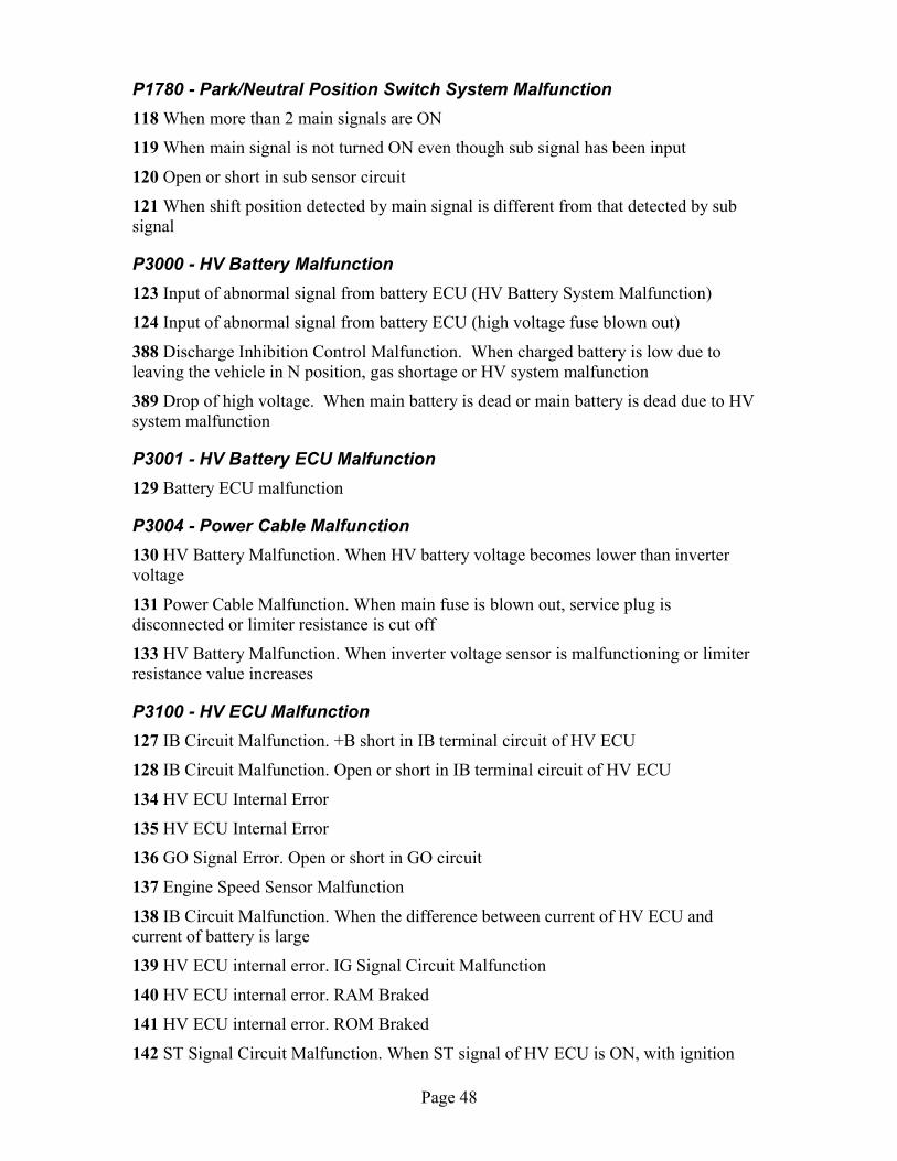
P1780 - Park/Neutral Position Switch System Malfunction118 When more than 2 main signals are ON
119 When main signal is not turned ON even though sub signal has been input
120 Open or short in sub sensor circuit
121 When shift position detected by main signal is different from that detected by subsignal
P3000 - HV Battery Malfunction123 Input of abnormal signal from battery ECU (HV Battery System Malfunction)
124 Input of abnormal signal from battery ECU (high voltage fuse blown out)
388 Discharge Inhibition Control Malfunction. When charged battery is low due toleaving the vehicle in N position, gas shortage or HV system malfunction
389 Drop of high voltage. When main battery is dead or main battery is dead due to HVsystem malfunction
P3001 - HV Battery ECU Malfunction129 Battery ECU malfunction
P3004 - Power Cable Malfunction130 HV Battery Malfunction. When HV battery voltage becomes lower than invertervoltage
131 Power Cable Malfunction. When main fuse is blown out, service plug isdisconnected or limiter resistance is cut off
133 HV Battery Malfunction. When inverter voltage sensor is malfunctioning or limiterresistance value increases
P3100 - HV ECU Malfunction127 IB Circuit Malfunction. +B short in IB terminal circuit of HV ECU
128 IB Circuit Malfunction. Open or short in IB terminal circuit of HV ECU
134 HV ECU Internal Error
135 HV ECU Internal Error
136 GO Signal Error. Open or short in GO circuit
137 Engine Speed Sensor Malfunction
138 IB Circuit Malfunction. When the difference between current of HV ECU andcurrent of battery is large
139 HV ECU internal error. IG Signal Circuit Malfunction
140 HV ECU internal error. RAM Braked
141 HV ECU internal error. ROM Braked
142 ST Signal Circuit Malfunction. When ST signal of HV ECU is ON, with ignition
Page 48

switch turned OFF
143 HV ECU internal error. Immobilizer Malfunction
144 HV ECU internal error. Primary Check Malfunction
145 HV ECU internal error. Primary Check Malfunction
146 HV ECU internal error. Primary Check Malfunction
147 HV ECU internal error. Primary Check Malfunction
148 HV ECU internal error. HV CPU Malfunction
149 HV ECU internal error. HV CPU Malfunction
150 HV ECU internal error. Motor CPU Malfunction
151 HV ECU internal error. Motor CPU Malfunction
152 HV ECU internal error. Motor CPU Malfunction
153 HV ECU internal error. Motor CPU Malfunction
154 HV ECU internal error. Motor CPU Malfunction
155 HV ECU internal error. Motor CPU Malfunction
156 HV ECU internal error. Motor CPU Malfunction
157 HV ECU internal error. Motor CPU Malfunction
158 HV ECU internal error. Motor CPU Malfunction
159 HV ECU internal error. Motor ECU Communication Circuit Malfunction
160 HV ECU internal error. Motor ECU Communication Circuit Malfunction
161 HV ECU internal error. Motor ECU Power Source Malfunction
162 HV ECU internal error. Motor ECU Power Source Malfunction
163 HV ECU internal error. Motor ECU Power Source Malfunction
164 HV ECU internal error. Motor ECU Power Source Malfunction
165 HV ECU internal error. Motor ECU Power Source Malfunction
166 HV ECU internal error. Motor R/D Malfunction
167 HV ECU internal error. Motor R/D Malfunction
168 HV ECU internal error. Motor R/D Malfunction
169 HV ECU internal error. Motor R/D Malfunction
170 HV ECU internal error. Motor R/D Malfunction
171 HV ECU internal error. Motor REF Signal Malfunction
172 HV ECU internal error. Motor REF Signal Malfunction
173 HV ECU internal error. Motor REF Signal Malfunction
174 HV ECU internal error. Motor Inverter Current Sensor Malfunction
175 HV ECU internal error. Motor Inverter Current Sensor Malfunction
Page 49

176 HV ECU internal error. Motor Gate Shutdown Signal Line Connection Malfunction
177 HV ECU internal error. Motor Main CPU Malfunction
178 HV ECU internal error. Motor Main CPU Malfunction
179 HV ECU internal error. Motor Main CPU Malfunction
180 HV ECU internal error. Rotation Angle Check CPU Malfunction
181 HV ECU internal error. Rotation Angle Check CPU Malfunction
182 HV ECU internal error. Rotation Angle Check CPU Malfunction
183 HV ECU internal error. Rotation Angle Check CPU Malfunction
184 HV ECU internal error. Rotation Angle Check CPU Malfunction
185 HV ECU internal error. Rotation Angle Check CPU Malfunction
186 HV ECU internal error. Rotation Angle Check CPU Malfunction
187 HV ECU internal error. Important RAM Malfunction
188 HV ECU internal error. Generator CPU Malfunction
189 HV ECU internal error. Generator CPU Malfunction
190 HV ECU internal error. Generator CPU Malfunction
191 HV ECU internal error. Generator CPU Malfunction
192 HV ECU internal error. Generator CPU Malfunction
193 HV ECU internal error. Generator CPU Malfunction
194 HV ECU internal error. Generator CPU Malfunction
195 HV ECU internal error. Generator CPU Malfunction
196 HV ECU internal error. Generator CPU Malfunction
197 HV ECU internal error. Generator R/D Malfunction
198 HV ECU internal error. Generator R/D Malfunction
199 HV ECU internal error. Generator R/D Malfunction
200 HV ECU internal error. Generator R/D Malfunction
201 HV ECU internal error. Generator R/D Malfunction
202 HV ECU internal error. Generator R/D Malfunction
203 HV ECU internal error. Generator Shutdown Signal Line Connection Malfunction
271 HV ECU internal error. Motor PWN Line Connection Malfunction
310 HV ECU internal error. Generator PWN Line Connection Malfunction
390 HV ECU internal error. Charge Inhibition Control Malfunction
391 HV ECU internal error. Motor CPU malfunction
392 HV ECU internal error. Motor CPU malfunction
393 HV ECU internal error. HV CPU Operation Malfunction
Page 50

P3101 - Engine System Malfunction204 Input of abnormal signal from the ECM (abnormal engine output)
205 Input of abnormal signal from the ECM (engine unable to start)
238 Transaxle Malfunction. When engine does not start even though cranking it
P3105 - Battery ECU Communication Circuit Malfunction206 When communication between battery ECU and HV ECU is abnormal 1 sec. afterignition is turned ON
207 When communication between battery ECU and HV ECU is abnormal 1 sec. afterignition is turned ON
208 When communication between battery ECU and HV ECU is abnormal 1 sec. afterignition is turned ON
P3106 - ECM Communication Circuit Malfunction209 When communication between ECM and HV ECU is abnormal 1 sec. after ignitionis turned ON
210 When communication between ECM and HV ECU is abnormal 1 sec. after ignitionis turned ON
211 When communication between ECM and HV ECU is abnormal 1 sec. after ignitionis turned ON
212 Input of abnormal signal from ECM
394 When ECM does not operate
P3107 - Airbag ECU Communication Circuit Malfunction213 When communication between airbag ECU and HV ECU is abnormal 10 sec. afterignition is turned ON
214 When communication between airbag ECU and HV ECU is abnormal 10 sec. afterignition is turned ON
215 When communication between airbag ECU and HV ECU is abnormal 10 sec. afterignition is turned ON
P3108 - A/C Amplifier Communication Circuit Malfunction216 When communication from A/C amplifier to HV ECU is abnormal
217 When communication from A/C amplifier to HV ECU is abnormal
P3109 - Brake ECU Communication Circuit Malfunction218 When communication between brake ECU and HV ECU is abnormal 1.5 sec. afterignition is turned ON
219 When communication between brake ECU and HV ECU is abnormal 1.5 sec. afterignition is turned ON
220 When communication between brake ECU and HV ECU is abnormal 1.5 sec. after
Page 51

ignition is turned ON
221 When communication between brake ECU and HV ECU is abnormal 1.5 sec. afterignition is turned ON
222 When abnormal data is received from brake ECU
P3110 - IGCT Relay Malfunction223 When IGCT relay is always closed
P3115 - System Main Relay Malfunction224 SMR Cont 1 Malfunction. Open or +B short in system main relay No. 1 circuit
225 SMR Cont 1 Malfunction. Short in system main relay No. 1 circuit
226 SMR Cont 2 Malfunction. Open or +B short in system main relay No. 2 circuit
227 SMR Cont 2 Malfunction. Short in system main relay No. 2 circuit
228 SMR Cont 3 Malfunction. Open or +B short in system main relay No. 3 circuit
229 SMR Cont 3 Malfunction. Short in system main relay No. 3 circuit
231 Deposit of SMR. System main relay + terminal deposited
232 Deposit of SMR. System main relay - terminal deposited
233 Deposit of SMR. System main relay + & - terminal deposited
P3120 - HV Transaxle Malfunction234 Energy Balance Malfunction. Small reduction of motor magnetism
235 Energy Balance Malfunction. Large reduction of motor magnetism
236 Energy Balance Malfunction. Small reduction of generator magnetism
237 Energy Balance Malfunction. Large reduction of generator magnetism
239 HV Transaxle Malfunction. Shaft damaged
240 HV Transaxle Malfunction. Generator locked
241 HV Transaxle Malfunction. Torque limiter sliding
242 HV Transaxle Malfunction. Planetary gear locked
243 Motor Resolver Malfunction. Motor resolver inter-phase short
244 Motor Resolver Malfunction. Motor resolver inter-phase short (When there is ahistory that the state of malfunction continued during inverter fail safe mode)
245 Motor Resolver Malfunction. Open or short in motor resolver circuit
246 Motor Resolver Malfunction. Open or short in motor resolver circuit (When there is ahistory that the state of malfunction continued during inverter fail safe mode)
247 Motor Temperature Sensor Malfunction. GND short in motor temperature sensor
248 Motor Temperature Sensor Malfunction. Motor temperature sensor malfunction
249 Motor Temperature Sensor Malfunction. Open or +B short in motor temperature
Page 52

sensor
250 Motor Temperature Sensor Malfunction. Motor temperature sensor performanceproblem
253 Generator Resolver Malfunction. Generator resolver inter-phase short
254 Generator Resolver Malfunction. Generator resolver inter-phase short (When there isa history that the state of malfunction continued during inverter fail safe mode)
255 Generator Resolver Malfunction. Open or short in generator resolver circuit
256 Generator Resolver Malfunction. Open or short in generator resolver circuit (Whenthere is a history that the state of malfunction continued during inverter fail safe mode)
257 Generator Temperature Sensor Malfunction. GND short in generator temperaturesensor
258 Generator Temperature Sensor Malfunction. Generator temperature sensormalfunction
259 Generator Temperature Sensor Malfunction. Open or +B short in generatortemperature sensor
260 Generator Temperature Sensor Malfunction. Generator temperature sensorperformance problem
P3125 - Converter & Inverter Assembly Malfunction263 DC/DC Converter Malfunction. +B short in DCDC converter NODD wiring
264 DC/DC Converter Malfunction. DCDC converter malfunction
265 DC/DC Converter Malfunction. Open or GND short in DCDC converter NODDwiring
266 VM Malfunction. Open or GND short in inverter voltage signal circuit
267 VM Malfunction. +B short in inverter voltage signal circuit
268 VM Malfunction. Inverter voltage signal is inconsistent with battery voltage
269 VM Malfunction. Inverter voltage sensor malfunction
270 VM Malfunction. Abnormality of line connection of inverter voltage signal circuit(When there is a history that the state of malfunction continued during inverter fail safemode)
272 Motor PWN Line Connection Malfunction. Abnormality of the line connection ofmotor PWM (When there is a history that the state of malfunction continued duringinverter fail safe mode)
273 Motor Inverter Gate Malfunction. Motor inverter malfunction
274 Motor Inverter Temperature. Open or +B short in motor inverter temperature sensor
275 Motor Inverter Temperature. GND short in motor inverter temperature sensor
276 Sensor Malfunction. Motor inverter temperature sensor malfunction
277 Sensor Malfunction. Motor inverter temperature sensor performance problem
Page 53

278 Motor Inverter Sinv. +B short in motor inverter stop signal circuit
279 Motor Inverter Sinv. Over voltage of inverter
280 Motor Inverter Sinv. Open or GND short in motor inverter stop signal circuit
281 Motor Inverter Sinv. Voltage drop of inverter power source
282 Motor Inverter Sinv. Inverter circuit broken
283 Motor Inverter Finv. +B short in motor inverter fail signal circuit
284 Motor Inverter Finv. Inverter overheating
285 Motor Inverter Finv. Open or GND short in motor inverter fail signal circuit
286 Motor Inverter Finv. Inverter circuit broken
287 Motor Inverter Finv. Inverter internal short
288 Motor Inverter Current Sensor Malfunction. Motor inverter current sensormalfunction (V phase sub sensor)
289 Motor Inverter Current Sensor Malfunction. Open in inverter current sensor (Vphase sub sensor)
290 Motor Inverter Current Sensor Malfunction. Motor inverter current sensormalfunction (V phase main sensor)
291 Motor Inverter Current Sensor Malfunction. (when there is a history that the state ofmalfunction continued during inverter fail safe mode)
292 Motor Inverter Current Sensor Malfunction. Open in motor inverter current sensor(V phase main sensor)
293 Motor Inverter Current Sensor Malfunction. (when there is a history that the stateof malfunction continued during inverter fail safe mode)
294 Motor Inverter Current Sensor Malfunction. Motor inverter current sensor V phaseperformance problem
295 Motor Inverter Current Sensor Malfunction. (when there is a history that the state ofmalfunction continued during inverter fail safe mode)
296 Motor Inverter Current Sensor Malfunction. Motor inverter current sensormalfunction (W phase sub sensor)
297 Motor Inverter Current Sensor Malfunction. Open in motor inverter current sensor(W phase sub sensor)
298 Motor Inverter Current Sensor Malfunction. Motor inverter current sensormalfunction (W phase main sensor)
299 Motor Inverter Current Sensor Malfunction. (when there is a history that the state ofmalfunction continued during inverter fail safe mode)
300 Motor Inverter Current Sensor Malfunction. Open in motor inverter current sensor(W phase main sensor)
301 Motor Inverter Current Sensor Malfunction. (when there is a history that the state ofmalfunction continued during inverter fail safe mode)
Page 54
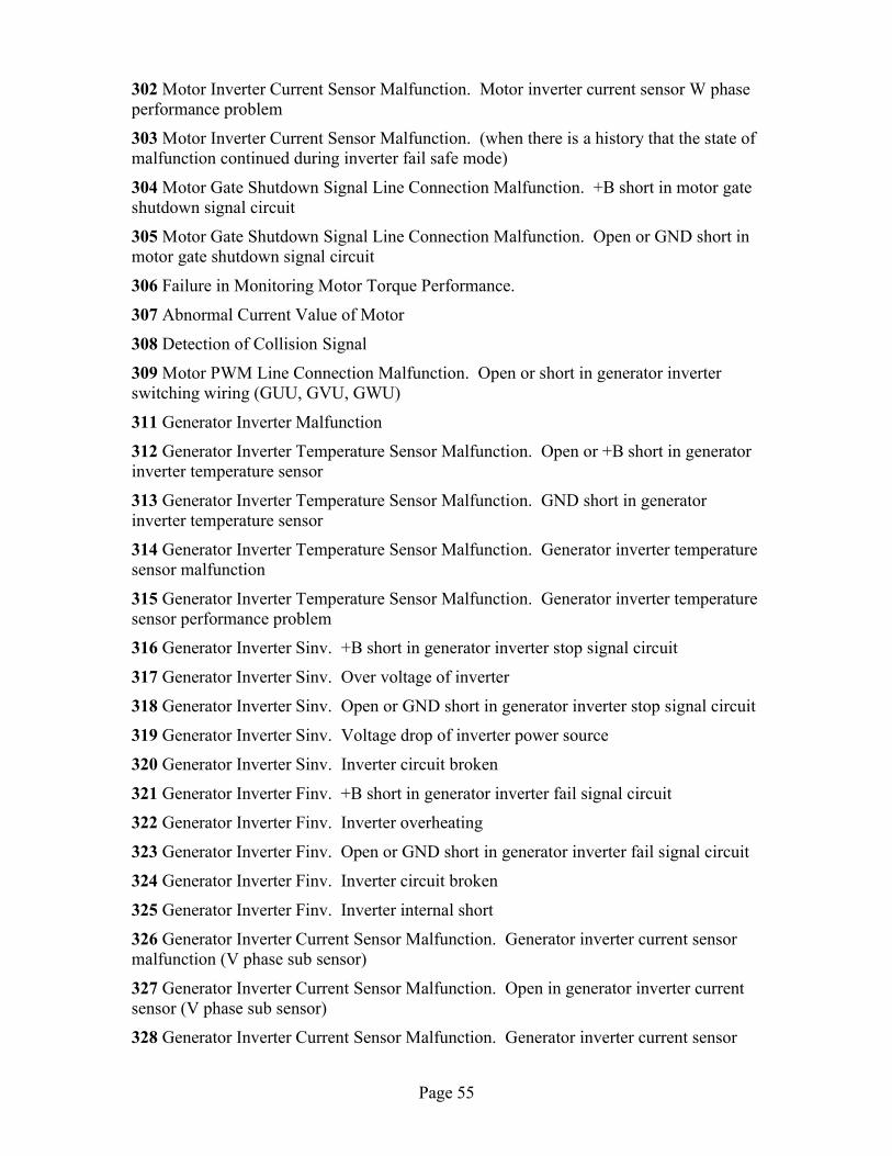
302 Motor Inverter Current Sensor Malfunction. Motor inverter current sensor W phaseperformance problem
303 Motor Inverter Current Sensor Malfunction. (when there is a history that the state ofmalfunction continued during inverter fail safe mode)
304 Motor Gate Shutdown Signal Line Connection Malfunction. +B short in motor gateshutdown signal circuit
305 Motor Gate Shutdown Signal Line Connection Malfunction. Open or GND short inmotor gate shutdown signal circuit
306 Failure in Monitoring Motor Torque Performance.
307 Abnormal Current Value of Motor
308 Detection of Collision Signal
309 Motor PWM Line Connection Malfunction. Open or short in generator inverterswitching wiring (GUU, GVU, GWU)
311 Generator Inverter Malfunction
312 Generator Inverter Temperature Sensor Malfunction. Open or +B short in generatorinverter temperature sensor
313 Generator Inverter Temperature Sensor Malfunction. GND short in generatorinverter temperature sensor
314 Generator Inverter Temperature Sensor Malfunction. Generator inverter temperaturesensor malfunction
315 Generator Inverter Temperature Sensor Malfunction. Generator inverter temperaturesensor performance problem
316 Generator Inverter Sinv. +B short in generator inverter stop signal circuit
317 Generator Inverter Sinv. Over voltage of inverter
318 Generator Inverter Sinv. Open or GND short in generator inverter stop signal circuit
319 Generator Inverter Sinv. Voltage drop of inverter power source
320 Generator Inverter Sinv. Inverter circuit broken
321 Generator Inverter Finv. +B short in generator inverter fail signal circuit
322 Generator Inverter Finv. Inverter overheating
323 Generator Inverter Finv. Open or GND short in generator inverter fail signal circuit
324 Generator Inverter Finv. Inverter circuit broken
325 Generator Inverter Finv. Inverter internal short
326 Generator Inverter Current Sensor Malfunction. Generator inverter current sensormalfunction (V phase sub sensor)
327 Generator Inverter Current Sensor Malfunction. Open in generator inverter currentsensor (V phase sub sensor)
328 Generator Inverter Current Sensor Malfunction. Generator inverter current sensor
Page 55

malfunction (V phase main sensor)
329 Generator Inverter Current Sensor Malfunction. (when there is a history that the stateof malfunction continued during inverter fail safe mode)
330 Generator Inverter Current Sensor Malfunction. Open in generator inverter currentsensor (V phase main sensor)
331 Generator Inverter Current Sensor Malfunction. (when there is a history that the stateof malfunction continued during inverter fail safe mode)
332 Generator Inverter Current Sensor Malfunction. Generator inverter current sensor Vphase performance problem
333 Generator Inverter Current Sensor Malfunction. (when there is a history that the stateof malfunction continued during inverter fail safe mode)
334 Generator Inverter Current Sensor Malfunction. Generator inverter current sensormalfunction (W phase sub sensor)
335 Generator Inverter Current Sensor Malfunction. Open in generator inverter currentsensor (W phase sub sensor)
336 Generator Inverter Current Sensor Malfunction. Generator inverter current sensormalfunction (W phase main sensor)
337 Generator Inverter Current Sensor Malfunction. (when there is a history that the stateof malfunction continued during inverter fail safe mode)
338 Generator Inverter Current Sensor Malfunction. Open in generator inverter currentsensor (W phase main sensor)
339 Generator Inverter Current Sensor Malfunction. (when there is a history that the stateof malfunction continued during inverter fail safe mode)
340 Generator Inverter Current Sensor Malfunction. Generator inverter current sensor Wphase performance problem
341 Generator Inverter Current Sensor Malfunction. (when there is a history that the stateof malfunction continued during inverter fail safe mode)
342 Motor Gate Shutdown Signal Line Connection. +B short in generator gate shutdownsignal
343 Motor Gate Shutdown Signal Line Connection. Open or GND short in generator gateshutdown signal circuit
344 Failure in Monitoring Generator Torque Performance
345 Abnormal Current Value of Generator
P3130 - Inverter Cooling System Malfunction346 Water pump system malfunction
347 Electric cooling fan system malfunction
P3135 - Circuit Breaker Sensor Malfunction348 GND short in circuit breaker sensor
Page 56

349 Open or +B short in circuit breaker sensor
P3140 - Interlock MalfunctionYou can make this DTC happen quite easily and safely by removing the service plug fromthe main battery and turning the car on.
350 Safety devices operating with vehicle is stopped (ILK signal ON)
351 Open circuit in interlock signal circuit while vehicle is running
P3145 - Vehicle Speed Sensor Circuit Malfunction352 No input of vehicle speed signal during cruise control driving
Page 57