ECR motor with integrated electronic control
3
Specifications Input voltage range 190-254V or 100-127V Output power range 3-25W Speed range 700-2300 RPM Max. input current (rated) 0.41A Insulation class Class A Thermal protection Self-resetting thermal protection, electronic locked rotor/stall detection Refrigerant compatibility HFC, CO2 and hydrocarbon (per IEC 60335-2-89 Annex BB) ATEX (EX) ATEX (IEC 60079-7 – Group 2, Category 3G) for motor models with ECR01*X*** IP rating IP55 Operating temp. range -30°C to +50°C (-22°F to +122°F) Storage temp. range -40°C to +80°C (-40°F to +176°F) Weight (max) 0.85kg (1.87lb) Approvals • User defined speeds and direction of rotation • Timed reverse • Dual speed operation • Energy efficient • RoHS and REACH compliant Suitable Fans* 150mm (6”) 200mm (8”) 230mm (9”) 254mm (10”) All Pitches 22° 28° 34° 40° 22° 28° 19° 22° 28° 1300 rpm 1550 rpm 1800 rpm *Indicative and dependent on model May not achieve rated rpm at all back pressures ECR motor with integrated electronic control
Transcript of ECR motor with integrated electronic control

Specifications
Input voltage range 190-254V or 100-127V
Output power range 3-25W
Speed range 700-2300 RPM
Max. input current (rated) 0.41A
Insulation class Class A
Thermal protection Self-resetting thermal protection, electronic locked rotor/stall detection
Refrigerant compatibility HFC, CO2 and hydrocarbon (per IEC 60335-2-89 Annex BB)
ATEX (EX) ATEX (IEC 60079-7 – Group 2, Category 3G) for motor models with ECR01*X***
IP rating IP55
Operating temp. range -30°C to +50°C (-22°F to +122°F)
Storage temp. range -40°C to +80°C (-40°F to +176°F)
Weight (max) 0.85kg (1.87lb)
Approvals
• User defined speedsand direction ofrotation
• Timed reverse
• Dual speed operation
• Energy efficient
• RoHS and REACHcompliant
Suitable Fans*
150mm (6”) 200mm (8”) 230mm (9”) 254mm (10”)
All Pitches 22° 28° 34° 40° 22° 28° 19° 22° 28°
1300 rpm
1550 rpm
1800 rpm
*Indicative and dependent on model
May not achieve rated rpm at all back pressures
ECR motor with integrated electronic control
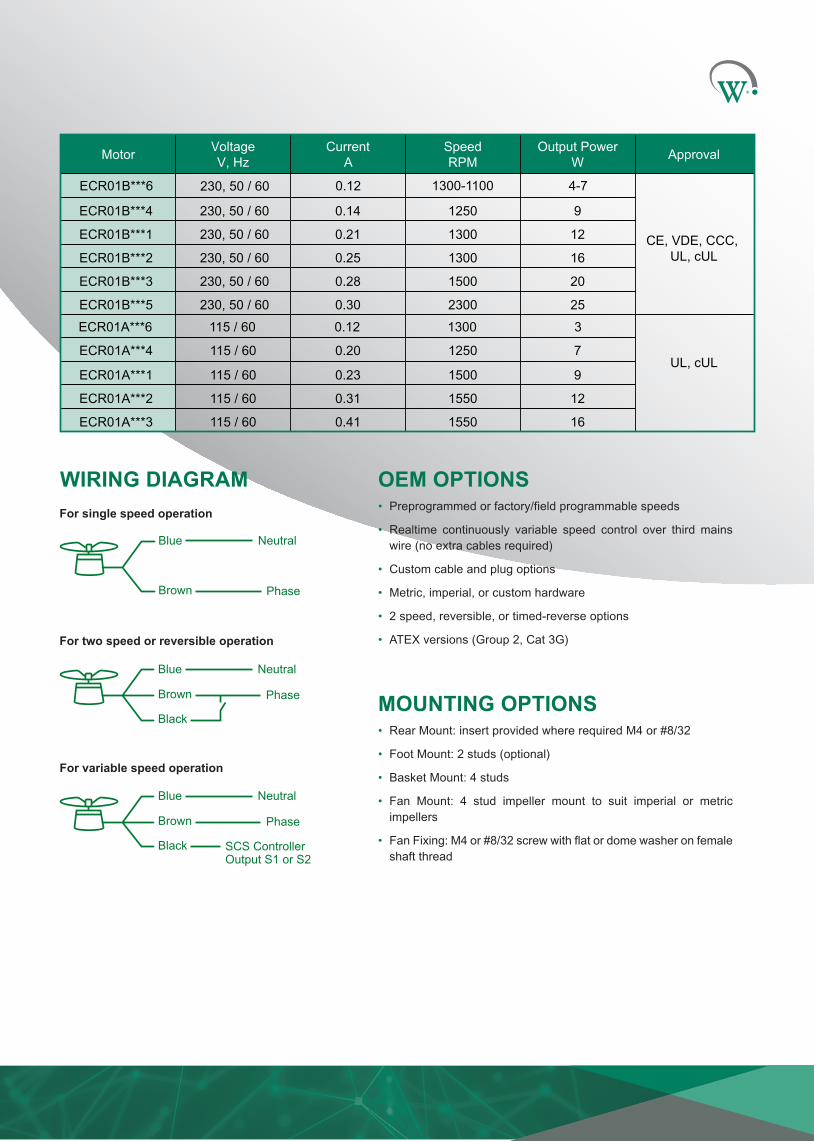
Motor VoltageV, Hz
Current A
Speed RPM
Output Power W Approval
ECR01B***4 230, 50 / 60 0.14 1250 9
CE, VDE, CCC, UL, cUL
ECR01B***1 230, 50 / 60 0.21 1300 12
ECR01B***2 230, 50 / 60 0.25 1300 16
ECR01B***3 230, 50 / 60 0.28 1500 20
230, 50 / 60 0.30 2300 25
ECR01A***4 115 / 60 0.20 1250 7UL, cUL
ECR01A***1 115 / 60 0.23 1500 9
ECR01A***2 115 / 60 0.31 1550 12
ECR01A***3 115 / 60 0.41 1550 16
ECR01A***6 115 / 60 0.12 1300 3
ECR01B***6 230, 50 / 60 0.12 1300-1100 4-7
ECR01B***5
OEM OPTIONS • Preprogrammed or factory/field programmable speeds
• Realtime continuously variable speed control over third mainswire (no extra cables required)
• Custom cable and plug options
• Metric, imperial, or custom hardware
• 2 speed, reversible, or timed-reverse options
• ATEX versions (Group 2, Cat 3G)
MOUNTING OPTIONS• Rear Mount: insert provided where required M4 or #8/32
• Foot Mount: 2 studs (optional)
• Basket Mount: 4 studs
• Fan Mount: 4 stud impeller mount to suit imperial or metricimpellers
• Fan Fixing: M4 or #8/32 screw with flat or dome washer on femaleshaft thread
WIRING DIAGRAM
For variable speed operation
Blue Neutral
Black
Brown
SCS ControllerOutput S1 or S2
Phase
For two speed or reversible operation
Blue Neutral
Black
Brown Phase
For single speed operation
Blue Neutral
Brown Phase

21 Arrenway Drive, Rosedale Auckland 0632, PO Box 302-533 North Harbour, Auckland 0751, New Zealand
P: +64 (9) 477 4500 E: [email protected] www.wdtl.com
© Wellington Drive Technologies Ltd. 2021 WT9177_i5 07/21
Dimensions A B C D E F G H I K
mm 88 26 38 52 500 34.5 46 77 67 71.4
inches 3.46 1.02 1.50 2.05 19.68 1.36 1.81 3.03 2.64 2.81
* 2x M4 or, #8-32 UNC threaded bolts are not included but available upon request.
K screws maximum depth is 6mm (0.23 inches).
Black Control lead
Blue Neutral
Brown Line / Phase
I
A
B
C
D
F
H
G
E
BlackBlueBrown
* 2x M4 or #8-32 UNC
4x M4 or #8-32 UNC, PCD K3x M4 or #8-32 UNC, PCD K
4x M4 or #8-32 UNC
M4 or #8-32 UNC