
ECP Milestone Report Engage second wave ECP/CEED ... · ECP Milestone Report Engage second wave...
27
ECP Milestone Report Engage second wave ECP/CEED applications WBS 2.2.6.06, Milestone CEED-MS23 Jean-Sylvain Camier Paul Fischer Ali Karakus Stefan Kerkemeier Tzanio Kolev Yu-Hsiang Lan David Medina Elia Merzari Misun Min Aleks Obabko Thilina Ratnayaka Dillon Shaver Ananias Tomboulides Vladimir Tomov Tim Warburton December 21, 2018
Transcript of ECP Milestone Report Engage second wave ECP/CEED ... · ECP Milestone Report Engage second wave...
ECP Milestone Report
Engage second wave ECP/CEED applications
WBS 2.2.6.06, Milestone CEED-MS23
Jean-Sylvain CamierPaul FischerAli Karakus
Stefan KerkemeierTzanio KolevYu-Hsiang LanDavid MedinaElia MerzariMisun Min
Aleks ObabkoThilina Ratnayaka
Dillon ShaverAnanias Tomboulides
Vladimir TomovTim Warburton
December 21, 2018
DOCUMENT AVAILABILITY
Reports produced after January 1, 1996, are generally available free via US Department ofEnergy (DOE) SciTech Connect.
Website http://www.osti.gov/scitech/
Reports produced before January 1, 1996, may be purchased by members of the publicfrom the following source:
National Technical Information Service5285 Port Royal RoadSpringfield, VA 22161Telephone 703-605-6000 (1-800-553-6847)TDD 703-487-4639Fax 703-605-6900E-mail [email protected] http://www.ntis.gov/help/ordermethods.aspx
Reports are available to DOE employees, DOE contractors, Energy Technology DataExchange representatives, and International Nuclear Information System representativesfrom the following source:
Office of Scientific and Technical InformationPO Box 62Oak Ridge, TN 37831Telephone 865-576-8401Fax 865-576-5728E-mail [email protected] http://www.osti.gov/contact.html
This report was prepared as an account of work sponsored by an agencyof the United States Government. Neither the United States Governmentnor any agency thereof, nor any of their employees, makes any warranty,express or implied, or assumes any legal liability or responsibility forthe accuracy, completeness, or usefulness of any information, apparatus,product, or process disclosed, or represents that its use would not infringeprivately owned rights. Reference herein to any specific commercialproduct, process, or service by trade name, trademark, manufacturer,or otherwise, does not necessarily constitute or imply its endorsement,recommendation, or favoring by the United States Government or anyagency thereof. The views and opinions of authors expressed herein donot necessarily state or reflect those of the United States Government orany agency thereof.
ECP Milestone Report
Engage second wave ECP/CEED applications
WBS 2.2.6.06, Milestone CEED-MS23
Office of Advanced Scientific Computing ResearchOffice of Science
US Department of Energy
Office of Advanced Simulation and ComputingNational Nuclear Security Administration
US Department of Energy
December 21, 2018
Exascale Computing Project (ECP) iii CEED-MS23
ECP Milestone Report
Engage second wave ECP/CEED applications
WBS 2.2.6.06, Milestone CEED-MS23
Approvals
Submitted by:
Tzanio Kolev, LLNL DateCEED PI
Approval:
Andrew R. Siegel, Argonne National Laboratory DateDirector, Applications DevelopmentExascale Computing Project
Exascale Computing Project (ECP) iv CEED-MS23

Revision Log
Version Creation Date Description Approval Date
1.0 December 21, 2018 Original
Exascale Computing Project (ECP) v CEED-MS23
EXECUTIVE SUMMARY
The CEED co-design center aims to impact a wide range of ECP application teams through focused 1-to-1 and1-to many interactions, facilitated by CEED application liaisons, ultimately targeted to provide easy-to-usediscretization libraries for high-order FEM-based application simulations.
The goal of this milestone was to extend our reach by identifying a second wave of ECP applications thatcan benefit from the efficient discretization algorithms and software developed in CEED. These applicationswere added to the list of the CEED first wave ECP applications (ExaSMR and MARBL), which continue tobe main targets for our work.
As part of the milestone, we also appointed liaisons on the CEED team that will be responsible forengaging each application, identifying its challenging discretization needs, and outlining a plan for interactionwith CEED. Working with all CEED thrusts, the liaisons will be ultimately responsible for ensuring theadoption of CEED technologies in each application as well as for demonstrating their benefits.
The selected second wave applications and CEED liaisons are:
• Urban – liaison Aleks Obabko (ANL)
• ExaWind – liaison Paul Fischer (UIUC)
• ExaAM – liaison Tzanio Kolev (LLNL)
In addition to details and results from these efforts, in this document we report on other project-wide activities performed in Q1 of FY19, including: engagements with performing scaling on V100 GPUs,collaboration with ECP/MPICH, participation in ECP/ST’s E4S release, the Laghos-2.0 release, papers,presentations, and other outreach efforts.
Exascale Computing Project (ECP) vi CEED-MS23
TABLE OF CONTENTS
Executive Summary vi
List of Figures viii
1 Introduction 1
2 Second Wave ECP/CEED Applications 12.1 Urban . . . . . . . . . . . . . . . . . . . . . . . . . . . . . . . . . . . . . . . . . . . . . . . . . 1
2.1.1 Lake Point Tower Capturing Turbulence at Fine Scale . . . . . . . . . . . . . . . . . . 12.1.2 Goose Island Mesh with Boundary Layer Refinement . . . . . . . . . . . . . . . . . . . 32.1.3 Downtown Chicago Block with 20 Buildings . . . . . . . . . . . . . . . . . . . . . . . . 32.1.4 NekNek Coupling Approach Toward 100∼200 Multiblocks. . . . . . . . . . . . . . . . 4
2.2 ExaWind . . . . . . . . . . . . . . . . . . . . . . . . . . . . . . . . . . . . . . . . . . . . . . . 52.2.1 Novel RANS Wall-Functions Yield Reduced Boundary Layer Resolution . . . . . . . . 52.2.2 Drag and Lift Coefficients for Wind Turbine Airfoil up to Re = 10M . . . . . . . . . . 62.2.3 Wall Function Approach Extended to Characteristics and JFNK . . . . . . . . . . . . 9
2.3 ExaAM . . . . . . . . . . . . . . . . . . . . . . . . . . . . . . . . . . . . . . . . . . . . . . . . 92.3.1 The ExaConstit Miniapp . . . . . . . . . . . . . . . . . . . . . . . . . . . . . . . . . . 11
3 Update on First Wave ECP/CEED Applications 123.1 ExaSMR . . . . . . . . . . . . . . . . . . . . . . . . . . . . . . . . . . . . . . . . . . . . . . . . 12
3.1.1 Accelerating Heat Transfer Simulations. . . . . . . . . . . . . . . . . . . . . . . . . . . 123.1.2 Accelerating Conjugate Heat Transfer Simulations. . . . . . . . . . . . . . . . . . . . . 14
3.2 MARBL . . . . . . . . . . . . . . . . . . . . . . . . . . . . . . . . . . . . . . . . . . . . . . . . 143.2.1 Laghos 2.0 . . . . . . . . . . . . . . . . . . . . . . . . . . . . . . . . . . . . . . . . . . 153.2.2 High-order Kernels in MARBL . . . . . . . . . . . . . . . . . . . . . . . . . . . . . . . 15
4 Other Project Activities 164.1 libParanumal: BP5 Strong-Scaling on 8 V100 GPUs . . . . . . . . . . . . . . . . . . . . . . . 164.2 MPICH Collaboration: BP5 Heterogeneous Memory Utilization Test . . . . . . . . . . . . . . 164.3 NAHOMCon19 . . . . . . . . . . . . . . . . . . . . . . . . . . . . . . . . . . . . . . . . . . . . 164.4 MFEM Part of E4S Release . . . . . . . . . . . . . . . . . . . . . . . . . . . . . . . . . . . . . 164.5 Outreach . . . . . . . . . . . . . . . . . . . . . . . . . . . . . . . . . . . . . . . . . . . . . . . 16
5 Conclusion 17
Exascale Computing Project (ECP) vii CEED-MS23
LIST OF FIGURES
1 Urban lake point tower simulation with Re = 8000, n = 160M , (N,E, P ) = (15, 47920, 16384)with 6000 timesteps. . . . . . . . . . . . . . . . . . . . . . . . . . . . . . . . . . . . . . . . . . 1
2 Lake point tower mesh with boundary layer refinement (E = 47920); The profile defining thetop-roof (top); The boundary layer refinement for the top-roof: zoom-out (center left) andzoom-in (center right) and the vertical direction (bottom). . . . . . . . . . . . . . . . . . . . . 2
3 Urban meshes needing improvement for Goose Island in Chicago area (top) and Chicagodowntown block including 20 buildings (bottom). . . . . . . . . . . . . . . . . . . . . . . . . . 3
4 NekNek: multimesh configurations. Two-meshes coupling (top left); Three-meshes coupling(top right). Strong-scaling (bottom left) with efficiency (bottom right). P represents thenumber of processors, N is the polynomial order, and n is the total number of grid points. . . 4
5 ExaWind mesh (DTU 10 MW reference wind turbine structure): point data with total of131841 (513×257) (top), down-sampled SEM mesh with E = 34×8 having coarser (bottom left)and denser (bottom right) boundary layers of the wing surface with 2 times lower resolution inparallel direction and 4 times lower resolution in the normal direction to the wing surface. . . 5
6 ExaWind RANS simulations for varying Reynolds numbers (Re = 100K, 1M, 10M), demon-strating profiles for steady solutions for the velocity, vorticity, k and ω, presure, using a meshwith E = 272(34× 8); Pressure is represented with three different set of stream lines referredas pr1, pr2, and pr3 (pr1: [-0.2, -0.1, 0.0, 0.1, 0.2], pr2: [-0.2, -0.1, -0.05, 0.0, 0.05, 0.1, 0.2],pr3: [-0.2, -0.15, -0.1, -0.05, 0.0, 0.05, 0.1, 0.15, 0.2]). . . . . . . . . . . . . . . . . . . . . . . . 7
7 ExaWind RANS steady solution, magnified images for Re = 10M for the velocity components(vx, vy: first row left and right), vorticity (second row left and right), k and ω (third row leftup and down, respectively), pressure on different streamlines on [-0.2, -0.1, 0.0, 0.1, 0.2] (thirdrow right), [-0.2, -0.1, -0.05, 0.0, 0.05, 0.1, 0.2] and [-0.2, -0.15, -0.1, -0.05, 0.0, 0.05, 0.1, 0.15,0.2] (fourth row left and right). . . . . . . . . . . . . . . . . . . . . . . . . . . . . . . . . . . . 8
8 Drag coefficient (Cd) and lift coefficient (Cl) for FFA airfoil from NREL (top left and right)for Re = 10M and from CEED (bottom left and right) for varying Reynolds numbers(Re = 100K, 1M, 5M, 10M). . . . . . . . . . . . . . . . . . . . . . . . . . . . . . . . . . . . . . 9
9 Zoom-in profiles for the drag (Cd) and lift (Cl) coefficients for the FFA airfoil simulationfrom CEED for Re = 10M , demonstrating oscillating behaviors for different resolutions withE = 34× 16 (top) and E = 34× 8 (bottom). . . . . . . . . . . . . . . . . . . . . . . . . . . . 10
10 Validation of the new wall function approach for Nek5000 RANS solver for different mesheswith varying boundary layer refinement. Minimum sizes of elements in the vertical directionare, 0.025, 0.1, and 0.25 from left to right on the domain y ∈ [0, 1], allowing the coarser meshesto have ∆t 50 ∼ 100× larger. . . . . . . . . . . . . . . . . . . . . . . . . . . . . . . . . . . . . 10
11 The ExaConstit miniapp aims to develop the capability to compute constitutive stress-straincurves given microstructural properties such as grain distribution and orientation. Thiswill be accomplished by solving quasi-static solid mechanics with a polycrystal model on arepresentative material volume. (Source: Nathan Barton, LLNL). . . . . . . . . . . . . . . . 11
12 ExaSMR steady thermal solution from longrod conjugate heat simulations (top and center)using Schwarz preconditioner with local solver with tensor approximation for the linearadvection diffusion operator, agreeing to the thermal solution from the standard Nek5000 usingBDF/EXT (bottom), demonstrating 20× speedup in total simulation time. . . . . . . . . . . 13
13 Dynamic AMR at different simulation times for the 3D Sedov explosion test in Laghos 2.0. . 1514 BP5 Strong-scaling on 8 V100 GPUs. p is the polynomial order, lx1=p + 1, and E is the
number of elements. . . . . . . . . . . . . . . . . . . . . . . . . . . . . . . . . . . . . . . . . . 1715 BP5 Strong-scaling: 6 GPU nodes (2×K40), ANL/LCRC Blues. . . . . . . . . . . . . . . . . 18
Exascale Computing Project (ECP) viii CEED-MS23
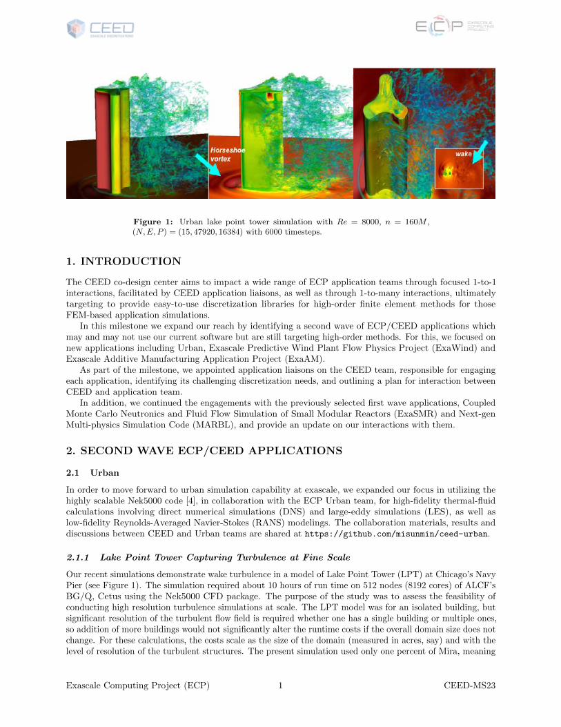
Figure 1: Urban lake point tower simulation with Re = 8000, n = 160M ,(N,E, P ) = (15, 47920, 16384) with 6000 timesteps.
1. INTRODUCTION
The CEED co-design center aims to impact a wide range of ECP application teams through focused 1-to-1interactions, facilitated by CEED application liaisons, as well as through 1-to-many interactions, ultimatelytargeting to provide easy-to-use discretization libraries for high-order finite element methods for thoseFEM-based application simulations.
In this milestone we expand our reach by identifying a second wave of ECP/CEED applications whichmay and may not use our current software but are still targeting high-order methods. For this, we focused onnew applications including Urban, Exascale Predictive Wind Plant Flow Physics Project (ExaWind) andExascale Additive Manufacturing Application Project (ExaAM).
As part of the milestone, we appointed application liaisons on the CEED team, responsible for engagingeach application, identifying its challenging discretization needs, and outlining a plan for interaction betweenCEED and application team.
In addition, we continued the engagements with the previously selected first wave applications, CoupledMonte Carlo Neutronics and Fluid Flow Simulation of Small Modular Reactors (ExaSMR) and Next-genMulti-physics Simulation Code (MARBL), and provide an update on our interactions with them.
2. SECOND WAVE ECP/CEED APPLICATIONS
2.1 Urban
In order to move forward to urban simulation capability at exascale, we expanded our focus in utilizing thehighly scalable Nek5000 code [4], in collaboration with the ECP Urban team, for high-fidelity thermal-fluidcalculations involving direct numerical simulations (DNS) and large-eddy simulations (LES), as well aslow-fidelity Reynolds-Averaged Navier-Stokes (RANS) modelings. The collaboration materials, results anddiscussions between CEED and Urban teams are shared at https://github.com/misunmin/ceed-urban.
2.1.1 Lake Point Tower Capturing Turbulence at Fine Scale
Our recent simulations demonstrate wake turbulence in a model of Lake Point Tower (LPT) at Chicago’s NavyPier (see Figure 1). The simulation required about 10 hours of run time on 512 nodes (8192 cores) of ALCF’sBG/Q, Cetus using the Nek5000 CFD package. The purpose of the study was to assess the feasibility ofconducting high resolution turbulence simulations at scale. The LPT model was for an isolated building, butsignificant resolution of the turbulent flow field is required whether one has a single building or multiple ones,so addition of more buildings would not significantly alter the runtime costs if the overall domain size does notchange. For these calculations, the costs scale as the size of the domain (measured in acres, say) and with thelevel of resolution of the turbulent structures. The present simulation used only one percent of Mira, meaning
Exascale Computing Project (ECP) 1 CEED-MS23
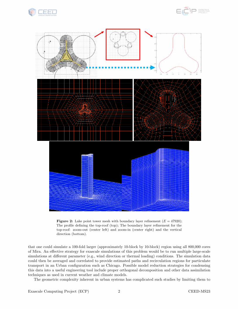
Figure 2: Lake point tower mesh with boundary layer refinement (E = 47920);The profile defining the top-roof (top); The boundary layer refinement for thetop-roof: zoom-out (center left) and zoom-in (center right) and the verticaldirection (bottom).
that one could simulate a 100-fold larger (approximately 10-block by 10-block) region using all 800,000 coresof Mira. An effective strategy for exascale simulations of this problem would be to run multiple large-scalesimulations at different parameter (e.g., wind direction or thermal loading) conditions. The simulation datacould then be averaged and correlated to provide estimated paths and recirculation regions for particulatetransport in an Urban configuration such as Chicago. Possible model reduction strategies for condensingthis data into a useful engineering tool include proper orthogonal decomposition and other data assimilationtechniques as used in current weather and climate models.
The geometric complexity inherent in urban systems has complicated such studies by limiting them to
Exascale Computing Project (ECP) 2 CEED-MS23
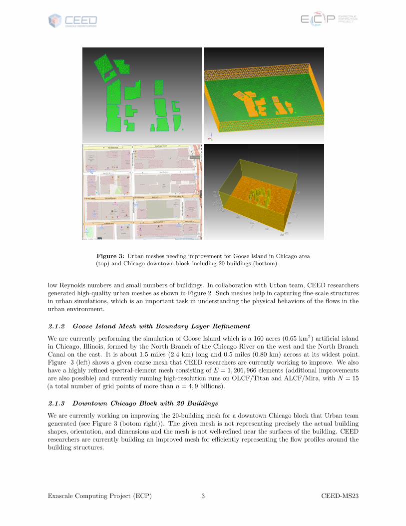
Figure 3: Urban meshes needing improvement for Goose Island in Chicago area(top) and Chicago downtown block including 20 buildings (bottom).
low Reynolds numbers and small numbers of buildings. In collaboration with Urban team, CEED researchersgenerated high-quality urban meshes as shown in Figure 2. Such meshes help in capturing fine-scale structuresin urban simulations, which is an important task in understanding the physical behaviors of the flows in theurban environment.
2.1.2 Goose Island Mesh with Boundary Layer Refinement
We are currently performing the simulation of Goose Island which is a 160 acres (0.65 km2) artificial islandin Chicago, Illinois, formed by the North Branch of the Chicago River on the west and the North BranchCanal on the east. It is about 1.5 miles (2.4 km) long and 0.5 miles (0.80 km) across at its widest point.Figure 3 (left) shows a given coarse mesh that CEED researchers are currently working to improve. We alsohave a highly refined spectral-element mesh consisting of E = 1, 206, 966 elements (additional improvementsare also possible) and currently running high-resolution runs on OLCF/Titan and ALCF/Mira, with N = 15(a total number of grid points of more than n = 4, 9 billions).
2.1.3 Downtown Chicago Block with 20 Buildings
We are currently working on improving the 20-building mesh for a downtown Chicago block that Urban teamgenerated (see Figure 3 (botom right)). The given mesh is not representing precisely the actual buildingshapes, orientation, and dimensions and the mesh is not well-refined near the surfaces of the building. CEEDresearchers are currently building an improved mesh for efficiently representing the flow profiles around thebuilding structures.
Exascale Computing Project (ECP) 3 CEED-MS23
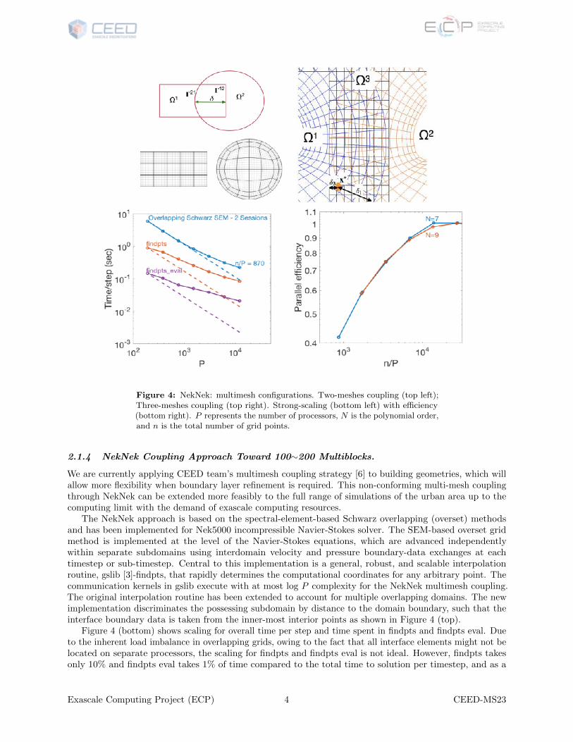
Figure 4: NekNek: multimesh configurations. Two-meshes coupling (top left);Three-meshes coupling (top right). Strong-scaling (bottom left) with efficiency(bottom right). P represents the number of processors, N is the polynomial order,and n is the total number of grid points.
2.1.4 NekNek Coupling Approach Toward 100∼200 Multiblocks.
We are currently applying CEED team’s multimesh coupling strategy [6] to building geometries, which willallow more flexibility when boundary layer refinement is required. This non-conforming multi-mesh couplingthrough NekNek can be extended more feasibly to the full range of simulations of the urban area up to thecomputing limit with the demand of exascale computing resources.
The NekNek approach is based on the spectral-element-based Schwarz overlapping (overset) methodsand has been implemented for Nek5000 incompressible Navier-Stokes solver. The SEM-based overset gridmethod is implemented at the level of the Navier-Stokes equations, which are advanced independentlywithin separate subdomains using interdomain velocity and pressure boundary-data exchanges at eachtimestep or sub-timestep. Central to this implementation is a general, robust, and scalable interpolationroutine, gslib [3]-findpts, that rapidly determines the computational coordinates for any arbitrary point. Thecommunication kernels in gslib execute with at most log P complexity for the NekNek multimesh coupling.The original interpolation routine has been extended to account for multiple overlapping domains. The newimplementation discriminates the possessing subdomain by distance to the domain boundary, such that theinterface boundary data is taken from the inner-most interior points as shown in Figure 4 (top).
Figure 4 (bottom) shows scaling for overall time per step and time spent in findpts and findpts eval. Dueto the inherent load imbalance in overlapping grids, owing to the fact that all interface elements might not belocated on separate processors, the scaling for findpts and findpts eval is not ideal. However, findpts takesonly 10% and findpts eval takes 1% of time compared to the total time to solution per timestep, and as a
Exascale Computing Project (ECP) 4 CEED-MS23
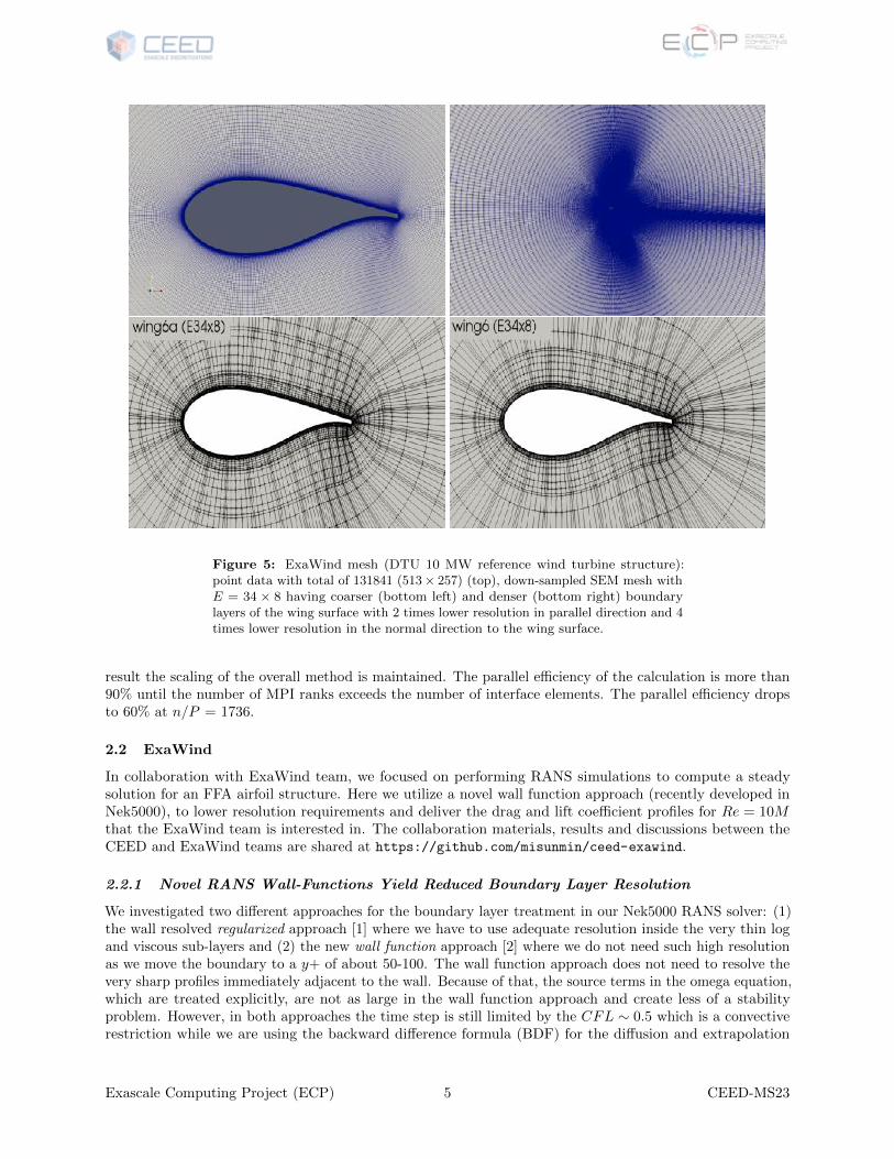
Figure 5: ExaWind mesh (DTU 10 MW reference wind turbine structure):point data with total of 131841 (513× 257) (top), down-sampled SEM mesh withE = 34 × 8 having coarser (bottom left) and denser (bottom right) boundarylayers of the wing surface with 2 times lower resolution in parallel direction and 4times lower resolution in the normal direction to the wing surface.
result the scaling of the overall method is maintained. The parallel efficiency of the calculation is more than90% until the number of MPI ranks exceeds the number of interface elements. The parallel efficiency dropsto 60% at n/P = 1736.
2.2 ExaWind
In collaboration with ExaWind team, we focused on performing RANS simulations to compute a steadysolution for an FFA airfoil structure. Here we utilize a novel wall function approach (recently developed inNek5000), to lower resolution requirements and deliver the drag and lift coefficient profiles for Re = 10Mthat the ExaWind team is interested in. The collaboration materials, results and discussions between theCEED and ExaWind teams are shared at https://github.com/misunmin/ceed-exawind.
2.2.1 Novel RANS Wall-Functions Yield Reduced Boundary Layer Resolution
We investigated two different approaches for the boundary layer treatment in our Nek5000 RANS solver: (1)the wall resolved regularized approach [1] where we have to use adequate resolution inside the very thin logand viscous sub-layers and (2) the new wall function approach [2] where we do not need such high resolutionas we move the boundary to a y+ of about 50-100. The wall function approach does not need to resolve thevery sharp profiles immediately adjacent to the wall. Because of that, the source terms in the omega equation,which are treated explicitly, are not as large in the wall function approach and create less of a stabilityproblem. However, in both approaches the time step is still limited by the CFL ∼ 0.5 which is a convectiverestriction while we are using the backward difference formula (BDF) for the diffusion and extrapolation
Exascale Computing Project (ECP) 5 CEED-MS23
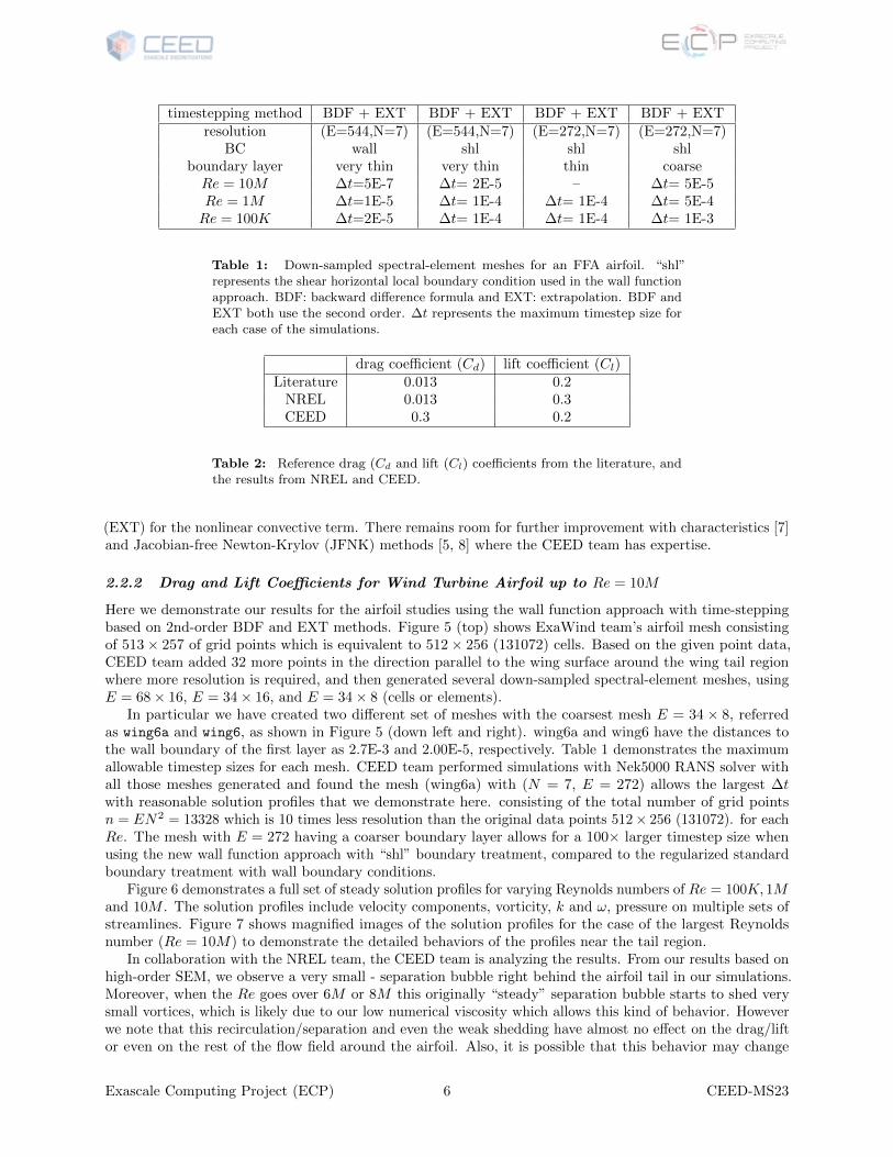
timestepping method BDF + EXT BDF + EXT BDF + EXT BDF + EXTresolution (E=544,N=7) (E=544,N=7) (E=272,N=7) (E=272,N=7)
BC wall shl shl shlboundary layer very thin very thin thin coarseRe = 10M ∆t=5E-7 ∆t= 2E-5 – ∆t= 5E-5Re = 1M ∆t=1E-5 ∆t= 1E-4 ∆t= 1E-4 ∆t= 5E-4Re = 100K ∆t=2E-5 ∆t= 1E-4 ∆t= 1E-4 ∆t= 1E-3
Table 1: Down-sampled spectral-element meshes for an FFA airfoil. “shl”represents the shear horizontal local boundary condition used in the wall functionapproach. BDF: backward difference formula and EXT: extrapolation. BDF andEXT both use the second order. ∆t represents the maximum timestep size foreach case of the simulations.
drag coefficient (Cd) lift coefficient (Cl)Literature 0.013 0.2
NREL 0.013 0.3CEED 0.3 0.2
Table 2: Reference drag (Cd and lift (Cl) coefficients from the literature, andthe results from NREL and CEED.
(EXT) for the nonlinear convective term. There remains room for further improvement with characteristics [7]and Jacobian-free Newton-Krylov (JFNK) methods [5, 8] where the CEED team has expertise.
2.2.2 Drag and Lift Coefficients for Wind Turbine Airfoil up to Re = 10M
Here we demonstrate our results for the airfoil studies using the wall function approach with time-steppingbased on 2nd-order BDF and EXT methods. Figure 5 (top) shows ExaWind team’s airfoil mesh consistingof 513× 257 of grid points which is equivalent to 512× 256 (131072) cells. Based on the given point data,CEED team added 32 more points in the direction parallel to the wing surface around the wing tail regionwhere more resolution is required, and then generated several down-sampled spectral-element meshes, usingE = 68× 16, E = 34× 16, and E = 34× 8 (cells or elements).
In particular we have created two different set of meshes with the coarsest mesh E = 34 × 8, referredas wing6a and wing6, as shown in Figure 5 (down left and right). wing6a and wing6 have the distances tothe wall boundary of the first layer as 2.7E-3 and 2.00E-5, respectively. Table 1 demonstrates the maximumallowable timestep sizes for each mesh. CEED team performed simulations with Nek5000 RANS solver withall those meshes generated and found the mesh (wing6a) with (N = 7, E = 272) allows the largest ∆twith reasonable solution profiles that we demonstrate here. consisting of the total number of grid pointsn = EN2 = 13328 which is 10 times less resolution than the original data points 512× 256 (131072). for eachRe. The mesh with E = 272 having a coarser boundary layer allows for a 100× larger timestep size whenusing the new wall function approach with “shl” boundary treatment, compared to the regularized standardboundary treatment with wall boundary conditions.
Figure 6 demonstrates a full set of steady solution profiles for varying Reynolds numbers of Re = 100K, 1Mand 10M . The solution profiles include velocity components, vorticity, k and ω, pressure on multiple sets ofstreamlines. Figure 7 shows magnified images of the solution profiles for the case of the largest Reynoldsnumber (Re = 10M) to demonstrate the detailed behaviors of the profiles near the tail region.
In collaboration with the NREL team, the CEED team is analyzing the results. From our results based onhigh-order SEM, we observe a very small - separation bubble right behind the airfoil tail in our simulations.Moreover, when the Re goes over 6M or 8M this originally “steady” separation bubble starts to shed verysmall vortices, which is likely due to our low numerical viscosity which allows this kind of behavior. Howeverwe note that this recirculation/separation and even the weak shedding have almost no effect on the drag/liftor even on the rest of the flow field around the airfoil. Also, it is possible that this behavior may change
Exascale Computing Project (ECP) 6 CEED-MS23
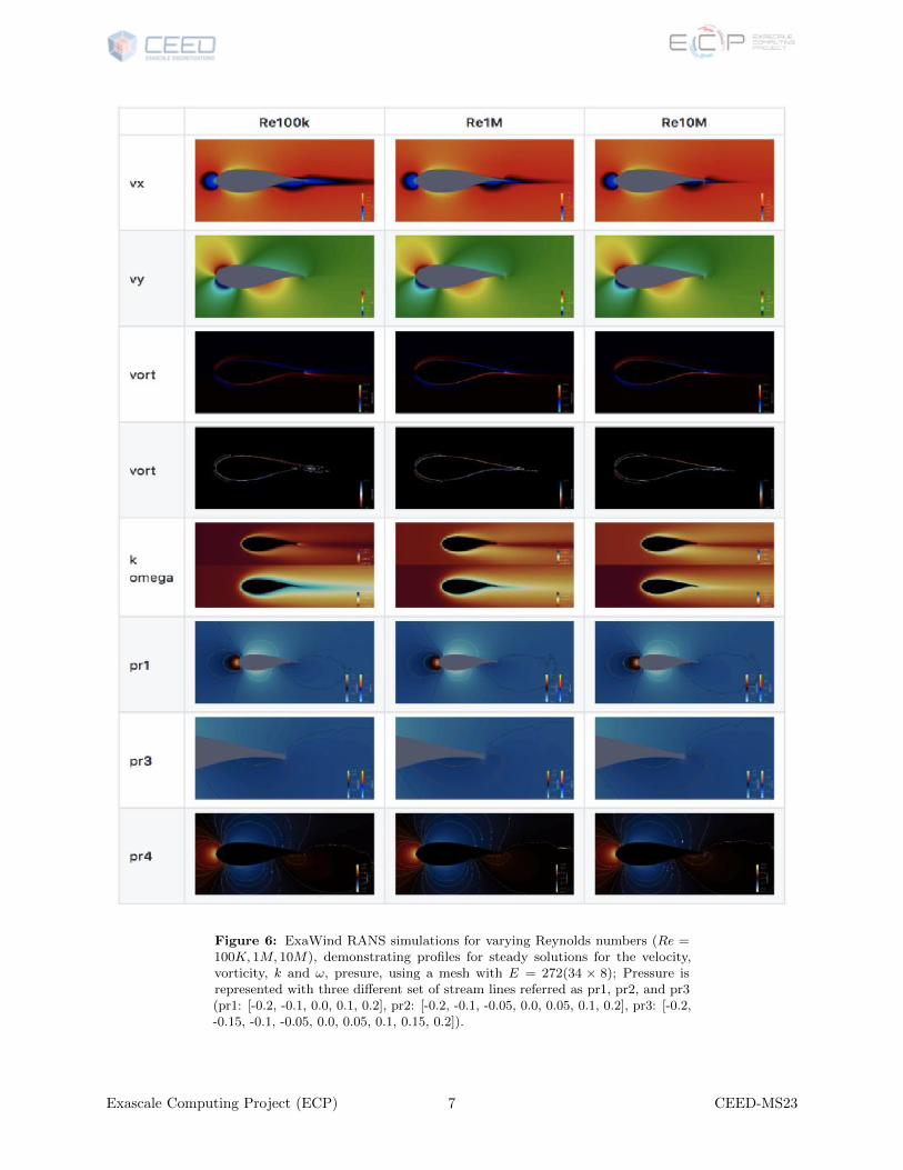
Figure 6: ExaWind RANS simulations for varying Reynolds numbers (Re =100K, 1M, 10M), demonstrating profiles for steady solutions for the velocity,vorticity, k and ω, presure, using a mesh with E = 272(34 × 8); Pressure isrepresented with three different set of stream lines referred as pr1, pr2, and pr3(pr1: [-0.2, -0.1, 0.0, 0.1, 0.2], pr2: [-0.2, -0.1, -0.05, 0.0, 0.05, 0.1, 0.2], pr3: [-0.2,-0.15, -0.1, -0.05, 0.0, 0.05, 0.1, 0.15, 0.2]).
Exascale Computing Project (ECP) 7 CEED-MS23
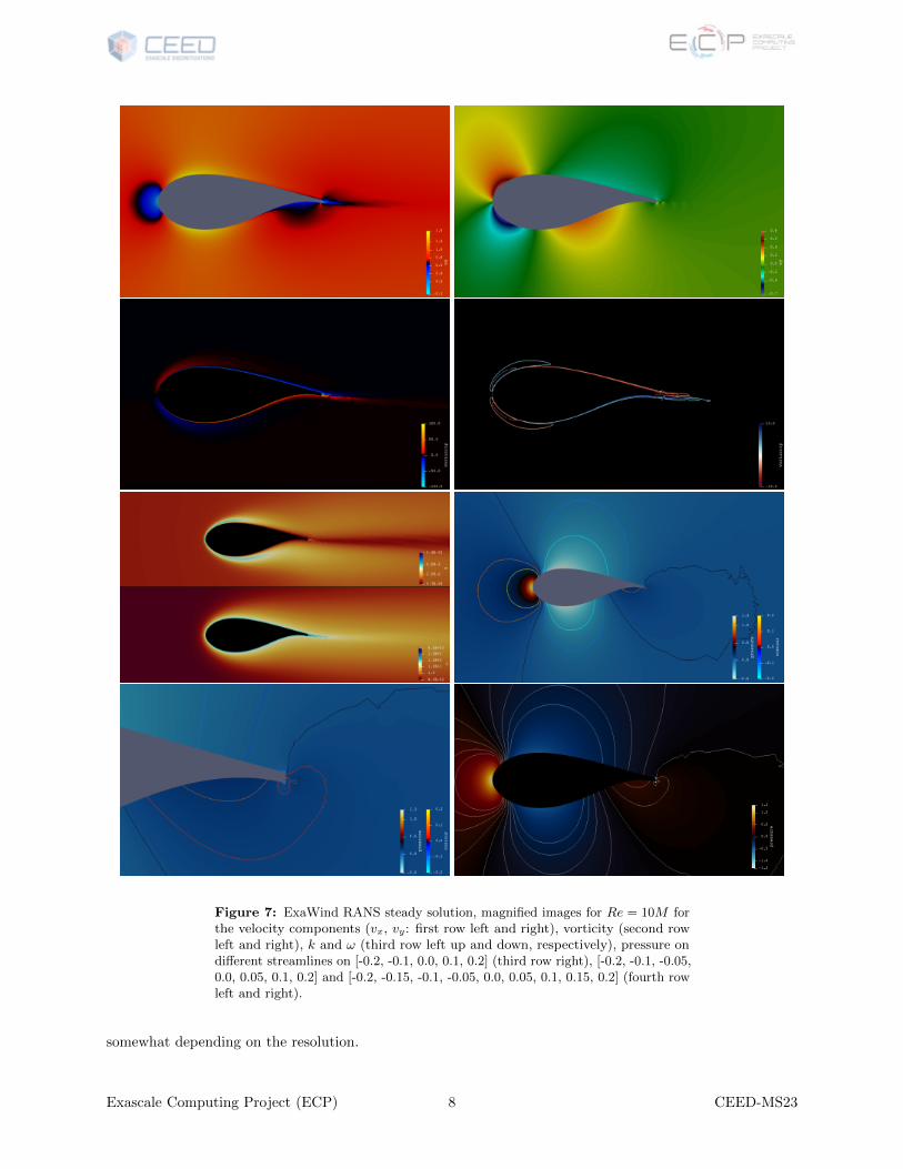
Figure 7: ExaWind RANS steady solution, magnified images for Re = 10M forthe velocity components (vx, vy: first row left and right), vorticity (second rowleft and right), k and ω (third row left up and down, respectively), pressure ondifferent streamlines on [-0.2, -0.1, 0.0, 0.1, 0.2] (third row right), [-0.2, -0.1, -0.05,0.0, 0.05, 0.1, 0.2] and [-0.2, -0.15, -0.1, -0.05, 0.0, 0.05, 0.1, 0.15, 0.2] (fourth rowleft and right).
somewhat depending on the resolution.
Exascale Computing Project (ECP) 8 CEED-MS23
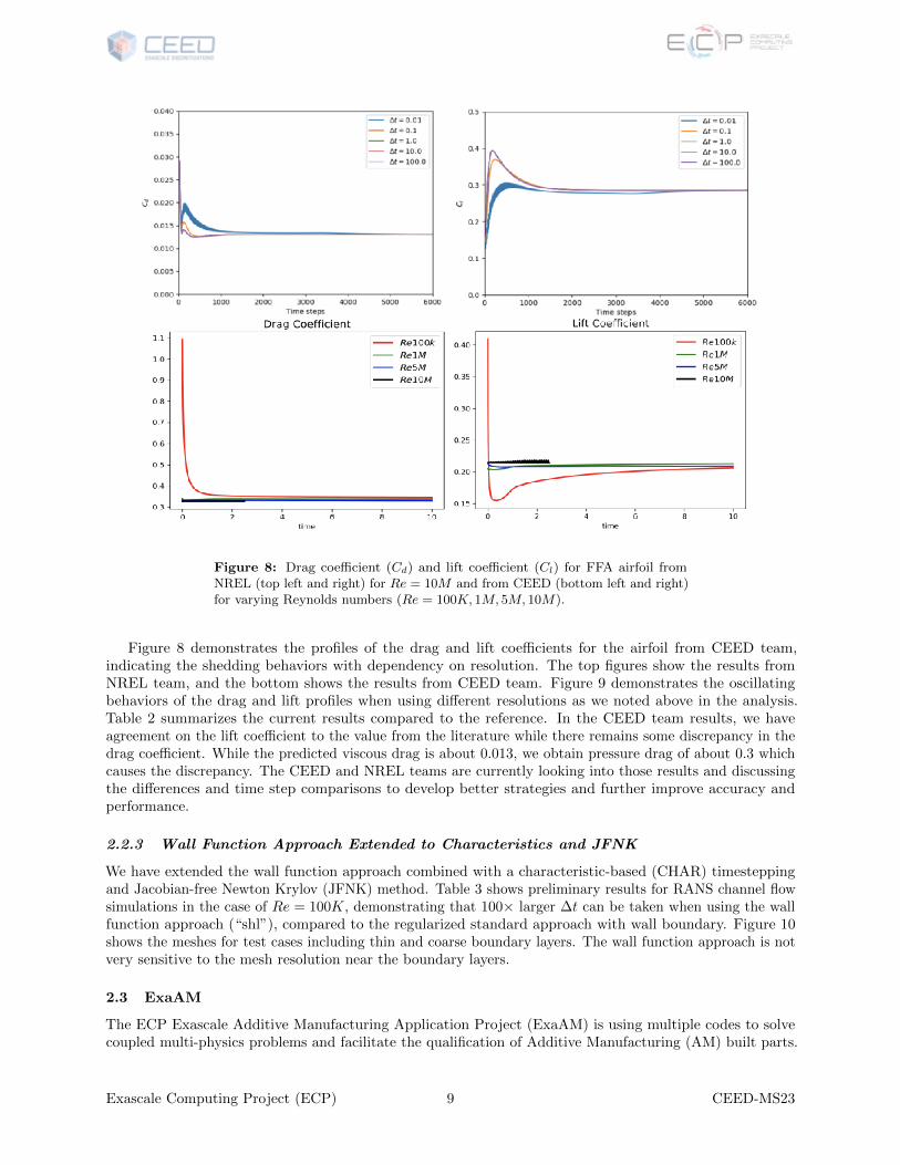
Figure 8: Drag coefficient (Cd) and lift coefficient (Cl) for FFA airfoil fromNREL (top left and right) for Re = 10M and from CEED (bottom left and right)for varying Reynolds numbers (Re = 100K, 1M, 5M, 10M).
Figure 8 demonstrates the profiles of the drag and lift coefficients for the airfoil from CEED team,indicating the shedding behaviors with dependency on resolution. The top figures show the results fromNREL team, and the bottom shows the results from CEED team. Figure 9 demonstrates the oscillatingbehaviors of the drag and lift profiles when using different resolutions as we noted above in the analysis.Table 2 summarizes the current results compared to the reference. In the CEED team results, we haveagreement on the lift coefficient to the value from the literature while there remains some discrepancy in thedrag coefficient. While the predicted viscous drag is about 0.013, we obtain pressure drag of about 0.3 whichcauses the discrepancy. The CEED and NREL teams are currently looking into those results and discussingthe differences and time step comparisons to develop better strategies and further improve accuracy andperformance.
2.2.3 Wall Function Approach Extended to Characteristics and JFNK
We have extended the wall function approach combined with a characteristic-based (CHAR) timesteppingand Jacobian-free Newton Krylov (JFNK) method. Table 3 shows preliminary results for RANS channel flowsimulations in the case of Re = 100K, demonstrating that 100× larger ∆t can be taken when using the wallfunction approach (“shl”), compared to the regularized standard approach with wall boundary. Figure 10shows the meshes for test cases including thin and coarse boundary layers. The wall function approach is notvery sensitive to the mesh resolution near the boundary layers.
2.3 ExaAM
The ECP Exascale Additive Manufacturing Application Project (ExaAM) is using multiple codes to solvecoupled multi-physics problems and facilitate the qualification of Additive Manufacturing (AM) built parts.
Exascale Computing Project (ECP) 9 CEED-MS23
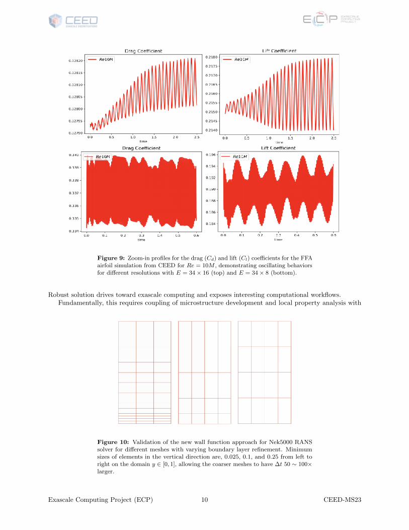
Figure 9: Zoom-in profiles for the drag (Cd) and lift (Cl) coefficients for the FFAairfoil simulation from CEED for Re = 10M , demonstrating oscillating behaviorsfor different resolutions with E = 34× 16 (top) and E = 34× 8 (bottom).
Robust solution drives toward exascale computing and exposes interesting computational workflows.Fundamentally, this requires coupling of microstructure development and local property analysis with
Figure 10: Validation of the new wall function approach for Nek5000 RANSsolver for different meshes with varying boundary layer refinement. Minimumsizes of elements in the vertical direction are, 0.025, 0.1, and 0.25 from left toright on the domain y ∈ [0, 1], allowing the coarser meshes to have ∆t 50 ∼ 100×larger.
Exascale Computing Project (ECP) 10 CEED-MS23
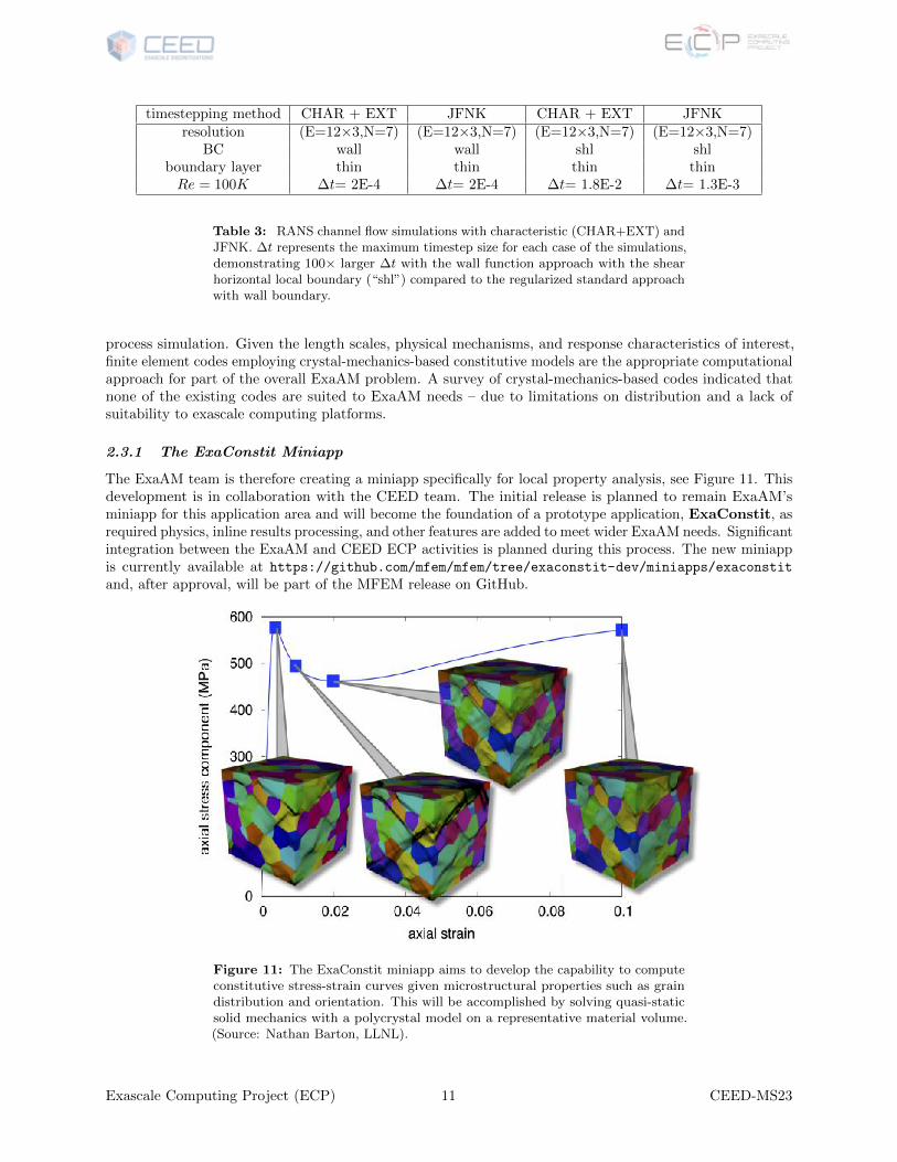
timestepping method CHAR + EXT JFNK CHAR + EXT JFNKresolution (E=12×3,N=7) (E=12×3,N=7) (E=12×3,N=7) (E=12×3,N=7)
BC wall wall shl shlboundary layer thin thin thin thinRe = 100K ∆t= 2E-4 ∆t= 2E-4 ∆t= 1.8E-2 ∆t= 1.3E-3
Table 3: RANS channel flow simulations with characteristic (CHAR+EXT) andJFNK. ∆t represents the maximum timestep size for each case of the simulations,demonstrating 100× larger ∆t with the wall function approach with the shearhorizontal local boundary (“shl”) compared to the regularized standard approachwith wall boundary.
process simulation. Given the length scales, physical mechanisms, and response characteristics of interest,finite element codes employing crystal-mechanics-based constitutive models are the appropriate computationalapproach for part of the overall ExaAM problem. A survey of crystal-mechanics-based codes indicated thatnone of the existing codes are suited to ExaAM needs – due to limitations on distribution and a lack ofsuitability to exascale computing platforms.
2.3.1 The ExaConstit Miniapp
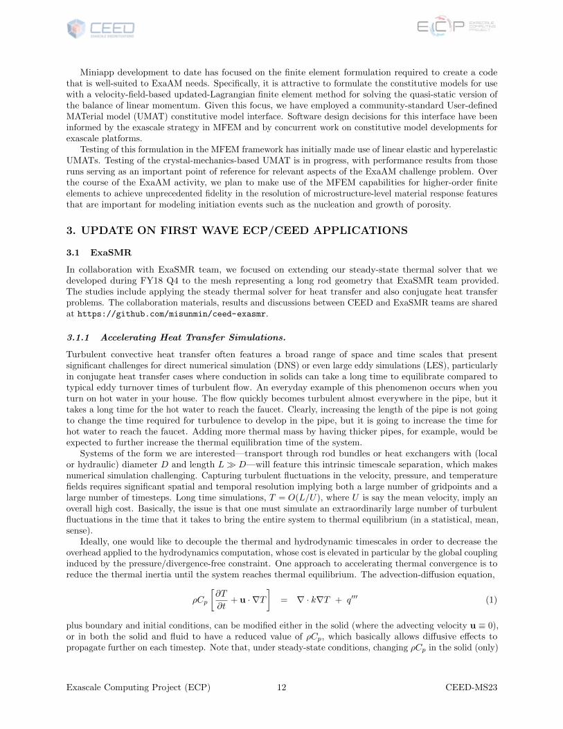
The ExaAM team is therefore creating a miniapp specifically for local property analysis, see Figure 11. Thisdevelopment is in collaboration with the CEED team. The initial release is planned to remain ExaAM’sminiapp for this application area and will become the foundation of a prototype application, ExaConstit, asrequired physics, inline results processing, and other features are added to meet wider ExaAM needs. Significantintegration between the ExaAM and CEED ECP activities is planned during this process. The new miniappis currently available at https://github.com/mfem/mfem/tree/exaconstit-dev/miniapps/exaconstit
and, after approval, will be part of the MFEM release on GitHub.
Figure 11: The ExaConstit miniapp aims to develop the capability to computeconstitutive stress-strain curves given microstructural properties such as graindistribution and orientation. This will be accomplished by solving quasi-staticsolid mechanics with a polycrystal model on a representative material volume.(Source: Nathan Barton, LLNL).
Exascale Computing Project (ECP) 11 CEED-MS23
Miniapp development to date has focused on the finite element formulation required to create a codethat is well-suited to ExaAM needs. Specifically, it is attractive to formulate the constitutive models for usewith a velocity-field-based updated-Lagrangian finite element method for solving the quasi-static version ofthe balance of linear momentum. Given this focus, we have employed a community-standard User-definedMATerial model (UMAT) constitutive model interface. Software design decisions for this interface have beeninformed by the exascale strategy in MFEM and by concurrent work on constitutive model developments forexascale platforms.
Testing of this formulation in the MFEM framework has initially made use of linear elastic and hyperelasticUMATs. Testing of the crystal-mechanics-based UMAT is in progress, with performance results from thoseruns serving as an important point of reference for relevant aspects of the ExaAM challenge problem. Overthe course of the ExaAM activity, we plan to make use of the MFEM capabilities for higher-order finiteelements to achieve unprecedented fidelity in the resolution of microstructure-level material response featuresthat are important for modeling initiation events such as the nucleation and growth of porosity.
3. UPDATE ON FIRST WAVE ECP/CEED APPLICATIONS
3.1 ExaSMR
In collaboration with ExaSMR team, we focused on extending our steady-state thermal solver that wedeveloped during FY18 Q4 to the mesh representing a long rod geometry that ExaSMR team provided.The studies include applying the steady thermal solver for heat transfer and also conjugate heat transferproblems. The collaboration materials, results and discussions between CEED and ExaSMR teams are sharedat https://github.com/misunmin/ceed-exasmr.
3.1.1 Accelerating Heat Transfer Simulations.
Turbulent convective heat transfer often features a broad range of space and time scales that presentsignificant challenges for direct numerical simulation (DNS) or even large eddy simulations (LES), particularlyin conjugate heat transfer cases where conduction in solids can take a long time to equilibrate compared totypical eddy turnover times of turbulent flow. An everyday example of this phenomenon occurs when youturn on hot water in your house. The flow quickly becomes turbulent almost everywhere in the pipe, but ittakes a long time for the hot water to reach the faucet. Clearly, increasing the length of the pipe is not goingto change the time required for turbulence to develop in the pipe, but it is going to increase the time forhot water to reach the faucet. Adding more thermal mass by having thicker pipes, for example, would beexpected to further increase the thermal equilibration time of the system.
Systems of the form we are interested—transport through rod bundles or heat exchangers with (localor hydraulic) diameter D and length L� D—will feature this intrinsic timescale separation, which makesnumerical simulation challenging. Capturing turbulent fluctuations in the velocity, pressure, and temperaturefields requires significant spatial and temporal resolution implying both a large number of gridpoints and alarge number of timesteps. Long time simulations, T = O(L/U), where U is say the mean velocity, imply anoverall high cost. Basically, the issue is that one must simulate an extraordinarily large number of turbulentfluctuations in the time that it takes to bring the entire system to thermal equilibrium (in a statistical, mean,sense).
Ideally, one would like to decouple the thermal and hydrodynamic timescales in order to decrease theoverhead applied to the hydrodynamics computation, whose cost is elevated in particular by the global couplinginduced by the pressure/divergence-free constraint. One approach to accelerating thermal convergence is toreduce the thermal inertia until the system reaches thermal equilibrium. The advection-diffusion equation,
ρCp
[∂T
∂t+ u · ∇T
]= ∇ · k∇T + q′′′ (1)
plus boundary and initial conditions, can be modified either in the solid (where the advecting velocity u ≡ 0),or in both the solid and fluid to have a reduced value of ρCp, which basically allows diffusive effects topropagate further on each timestep. Note that, under steady-state conditions, changing ρCp in the solid (only)
Exascale Computing Project (ECP) 12 CEED-MS23

Figure 12: ExaSMR steady thermal solution from longrod conjugate heatsimulations (top and center) using Schwarz preconditioner with local solver withtensor approximation for the linear advection diffusion operator, agreeing tothe thermal solution from the standard Nek5000 using BDF/EXT (bottom),demonstrating 20× speedup in total simulation time.
Exascale Computing Project (ECP) 13 CEED-MS23
results no change to the steady-state solution because ρCp in the solid has no influence once the temperatureequilibrates since ∂T
∂t and u are both zero there.A drawback of the preceding approach is that it does not accelerate the convergence of the thermal
advection, which is critical for long domains such as flow of hot water in a house or flow in reactors with longrod bundles. An approach that addresses this problem directly is to periodically “freeze” the turbulent velocityfield, u(x, t), and to advect over times τ � ∆t, where ∆t is the step size for the Navier-Stokes/advection-diffusion (NS/AD) solver. One can even take τ = L/U , which is the mean flow-through time, or τ =∞. Thesavings with this approach is two-fold. First, solution of the advection-diffusion equation is much cheaperthan solving the Navier-Stokes equations at each step. Second, for τ =∞, one can use a steady-state solver,which can result in considerable savings over time marching to a steady-state solution.
Note that in the case of a steady-state solver, there is no real point to “periodically” performing the cycle,
• freeze the velocity,
• solve the steady-state temperature equation,
• advance NS/AD,
• repeat,
because the steady-state thermal solution has no history and will reach a new (spurious) equilibrium in themiddle of each cycle. One might use this approach, however, to generate a sequence of plausible states overwhich statistics could be collected. Moreover, a single pass through the preceding sequence could provide avery good initial condition for DNS or LES of the NS/AD problem.
Still another viable acceleration technique is to replace u(x, t) with a surrogate, u(x, t), coming from areduced-order model based on, say, proper-orthogonal decomposition (POD). This is the approach currentlybeing pursued at UIUC in the spectral element analysis lab (SEAL).
3.1.2 Accelerating Conjugate Heat Transfer Simulations.
In collaboration with ExaSMR team, we further extended testing of our steady thermal solver for theconjugate heat transfer problem. The CEED team was given pre-defined velocity and varying viscosity datathat the ExaSMR team obtained from Nek5000 RANS simulations using the long rod geometry shown inFigure 12 (top) and we applied our steady-state thermal solver with the data and mesh given. Figure 12demonstrates validation of our thermal solution which agrees with the temperature profiles obtained by theNS and thermal simulation over time with the standard timestepping based on the BDF/EXT approach. Ourpreliminary measurement in timings shows 20× of speedup in getting steady thermal solution, compared tothe standard approach. Our next steps are to perform performance tests and extend the simulation capabilityfor much larger problem with 17× 17 rod bundles.
3.2 MARBL
The MARBL multi-physics code at LLNL has been working together with CEED researchers on getting theLagrangian (moving-mesh) phase of its multi-material ALE hydrodynamics capability running on GPUs.This effort has been utilizing the kernels and abstractions developed under CEED in both the MFEM libraryand the Laghos miniapp.
As described in previous reports, the MARBL code utilizes high-order continuous and discontinuousGalerkin methods from MFEM for solving the conservation laws described by the multi-material Eulerequations on a moving, high-order mesh. The Laghos miniapp, developed in CEED, is a simplified version ofthe Lagrange phase for the case of a single material and a simplified material stress (a scalar pressure derivedfrom a simple ideal gas equation of state). The MARBL code in contrast, is multi-material and has manyoptions for the material stress (including elastic-plastic stress, magnetic stress, radiations stress, etc.).
Nevertheless, the compute intensive, finite element operations for partial assembly of the mass and forcematrices are identical which allows the MARBL code to directly benefit from developments in optimizing /porting these kernels in the Laghos miniapp. Last year, a major effort was completed to refactor the Lagrangephase of MARBL to be based on partial assembly as in Laghos.
Exascale Computing Project (ECP) 14 CEED-MS23
3.2.1 Laghos 2.0
In the past period the CEED team released version 2.0 of Laghos. The major advance in this release is theintroduction of GPU-based versions of the miniapp, namely, its pure CUDA, OCCA, and RAJA versions.The release also includes a version that demonstrates the AMR capabilities of MFEM in the context ofLaghos. In addition, several minor improvements were made in the baseline MPI-based version, along with asynchronization of its serial variant.
The pure CUDA version rewrites the major computation kernels of Laghos without utilizing any inter-mediate abstraction layers. This version can be used as a performance baseline for abstraction-based GPUimplementations. The OCCA and RAJA versions, as their names suggest, correspond to implementations ofLaghos based on Virginia Tech’s OCCA and LLNL’s RAJA abstraction layers.
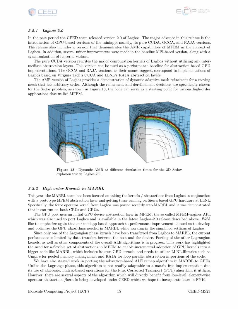
The AMR version of Laghos provides a demonstration of dynamic adaptive mesh refinement for a movingmesh that has arbitrary order. Although the refinement and derefinement decisions are specifically chosenfor the Sedov problem, as shown in Figure 13, the code can serve as a starting point for various high-orderapplications that utilize MFEM.
Figure 13: Dynamic AMR at different simulation times for the 3D Sedovexplosion test in Laghos 2.0.
3.2.2 High-order Kernels in MARBL
This year, the MARBL team has been focused on taking the kernels / abstractions from Laghos in conjunctionwith a prototype MFEM abstraction layer and getting these running on Sierra based GPU hardware at LLNL.Specifically, the force operator kernel from Laghos was ported recently into MARBL and it was demonstratedthat it can run on both CPUs and GPUs.
The GPU port uses an initial GPU device abstraction layer in MFEM, the so called MFEM-engines API,which was also used to port Laghos and is available in the latest Laghos-2.0 release described above. We’dlike to emphasize again that our miniapp-based approach to performance improvement allowed us to developand optimize the GPU algorithms needed in MARBL while working in the simplified settings of Laghos.
Since only one of the Lagrangian phase kernels have been transferred from Laghos to MARBL, the currentperformance is limited by data transfers between the host and the device. Porting of the other Lagrangiankernels, as well as other components of the overall ALE algorithms is in progress. This work has highlightedthe need for a flexible set of abstractions in MFEM to enable incremental adoption of GPU kernels into abigger code like MARBL, which includes its own GPU kernels, and needs to utilize LLNL libraries such asUmpire for pooled memory management and RAJA for loop parallel abstraction in portions of the code.
We have also started work in porting the advection-based ALE remap algorithm in MARBL to GPUs.Unlike the Lagrange phase, this algorithm is not readily adaptable to a matrix free implementation dueits use of algebraic, matrix-based operations for the Flux Corrected Transport (FCT) algorithm it utilizes.However, there are several aspects of the algorithm which will directly benefit from low-level, element-wiseoperator abstractions/kernels being developed under CEED which we hope to incorporate later in FY19.
Exascale Computing Project (ECP) 15 CEED-MS23
4. OTHER PROJECT ACTIVITIES
4.1 libParanumal: BP5 Strong-Scaling on 8 V100 GPUs
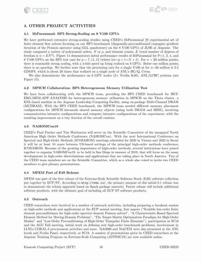
We have performed extensive strong-scaling studies using CEED’s libParanumal [9] experimental set offinite element flow solvers focusing on our BP5 benchmark (diagonally-preconditioned conjugate gradientiteration of the Poisson operator using GLL quadrature) on the 8 V100 GPUs of JLSE at Argonne. Thestudy compared a variety of polynomial orders, N or p, and element counts, E (total number of degrees offreedom is n = EN3). Figure 14 demonstrates initial performance results of libParanumal for P=1, 2, 4, and8 V100 GPUs on the BP5 test case for p = 7, 11, 15 (where lx1=p+ 1=N + 1). For n = 20 million points,there is reasonable strong scaling, with a 4-fold speed up being realized on 8 GPUs. Below one million points,there is no speedup. We further note that the processing rate for a single V100 at for n=20 million is 2.5GDOFS, which is about 20 times that realized on a single node of ANL’s BG/Q, Cetus.
We also demonstrate the performance on 6 GPU nodes (2× Nvidia K40), ANL/LCRC systems (seeFigure 15).
4.2 MPICH Collaboration: BP5 Heterogeneous Memory Utilization Test
We have been collaborating with the MPICH team, providing the BP5 CEED benchmark for HET-ERO MEM APP ANALYSIS for heterogeneous memory utilization in MPICH on the Theta cluster, aKNL-based machine in the Argonne Leadership Computing Facility, using on-package Multi-Channel DRAM(MCDRAM). With the BP5 CEED benchmark, the MPICH team needed different memory placementconfigurations for MPICH intranode shared memory objects (using both DRAM and HBM), involvingcommunication intensive configurations and compute intensive configurations of the experiment, with theresulting improvement on a tiny fraction of the overall runtime.
4.3 NAHOMCon19
CEED’s Paul Fischer and Tim Warburton will serve on the Scientific Committee of the inaugural NorthAmerican High Order Methods Conference (NAHOMCon). With the next International Conference onSpectral and High-Order Methods (ICOSAHOM) meetings scheduled for 2020 in Vienna and 2022 in Seoul,it will be at least 10 years between US-based settings of the principal high-order methods conference,ICOSAHOM. Because of the growing importance of high-order methods, several institutions have joinedtogether to organize NAHOMCon19, to be held in San Diego in summer of 2019, that will focus on the manydevelopments in high-order discretizations and applications that are taking place in North America. Two ofthe CEED team members are on the Scientific Committee, which as a whole also voted to invite two CEEDmembers to give plenary presentations.
4.4 MFEM Part of E4S Release
MFEM was part of the first release of the Extreme-Scale Scientific Software Stack (E4S) software collectionput together by ECP/ST, According to http://e4s.io/, the primary purpose of this initial 0.1 release wasto demonstrate the release approach based on Spack package maturity. Future release will include additionalsoftware products, with the ultimate goal of including all ECP ST software products.
4.5 Outreach
CEED researchers were involved in a number of outreach activities, including preparing a breakout sessionon high-order methods and applications at the ECP annual meeting, four papers (“Scalable low-order finiteelement preconditioners for high-order spectral element Poisson solvers”, “A Characteristic-Based SpectralElement Method for Moving-Domain Problems”, “The Target-Matrix Optimization Paradigm for High-OrderMeshes” and “Low-Order Preconditioning of High-Order Triangular Finite Elements”), participation in SC18and the AGU Fall meeting, initial work on defining new high-order benchmark problems, involvement inLLNLs CORAL-2 procurement activities and more. Nek5000 and NekCEM were also presented at the ANLbooth and Nvidia Panel, respectively, at SC18. A number of presentations given by CEED researchers at theArgonne Training Program on Extreme-Scale Computing (ATPESC18) are now available online.
Exascale Computing Project (ECP) 16 CEED-MS23
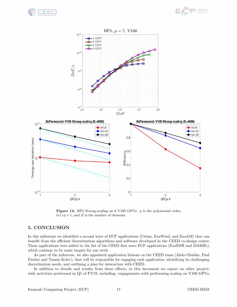
Figure 14: BP5 Strong-scaling on 8 V100 GPUs. p is the polynomial order,lx1=p + 1, and E is the number of elements.
5. CONCLUSION
In this milestone we identified a second wave of ECP applications (Urban, ExaWind, and ExaAM) that canbenefit from the efficient discretization algorithms and software developed in the CEED co-design center.These applications were added to the list of the CEED first wave ECP applications (ExaSMR and MARBL),which continue to be main targets for our work.
As part of the milestone, we also appointed application liaisons on the CEED team (Aleks Obabko, PaulFischer and Tzanio Kolev), that will be responsible for engaging each application, identifying its challengingdiscretization needs, and outlining a plan for interaction with CEED.
In addition to details and results from these efforts, in this document we report on other project-wide activities performed in Q1 of FY19, including: engagements with performing scaling on V100 GPUs,
Exascale Computing Project (ECP) 17 CEED-MS23
Figure 15: BP5 Strong-scaling: 6 GPU nodes (2×K40), ANL/LCRC Blues.
collaboration with ECP/MPICH, participation in ECP/ST’s E4S release, the Laghos-2.0 release, papers,presentations, and other outreach efforts.
ACKNOWLEDGMENTS
This research was supported by the Exascale Computing Project (ECP), Project Number: 17-SC-20-SC,a collaborative effort of two DOE organizations—the Office of Science and the National Nuclear SecurityAdministration—responsible for the planning and preparation of a capable exascale ecosystem—includingsoftware, applications, hardware, advanced system engineering, and early testbed platforms—to support thenation’s exascale computing imperative.
This work performed under the auspices of the U.S. Department of Energy by Lawrence LivermoreNational Laboratory under Contract DE-AC52-07NA27344, LLNL-TR-764597.
REFERENCES
[1] Tomboulides A, Aithal M, Fischer P, Merzari E, Obabko A, and Shaver D. A novel numerical treatementof the near-wall regions in the k-ω class of the rans models. International Journal of Heat and Fluid Flow,72:186–199, 2018.
[2] Kuzman D, Mierka O, and Turek S. On the implementation of the k-ω turbulence model in incompressibleflow solvers based on a finite element discretisation. International Journal of Computing Science andMathematics archive, 1:193–206, 2007.
[3] P. Fischer and J. Lottes. gslib: scalable communication library, https://github.com/gslib/gslib. 2008.
[4] P. Fischer, J. Lottes, and S. Kerkemeier. Nek5000: Open source spectral element CFD solver.http://nek5000.mcs.anl.gov and https://github.com/nek5000/nek5000. 2008.
[5] Dana A Knoll and David E Keyes. Jacobian-free newton-krylov methods: a survey of approaches andapplications. Journal of Computational Physics, 193(2):357–397, 2004.
Exascale Computing Project (ECP) 18 CEED-MS23
[6] Ketan Mittal, Som Dutta, and Paul Fischer. Nonconforming schwarz-spectral element methods forincompressible flow. submitted, 2018.
[7] S. Patel, P. Fischer, M. Min, and A. Tomboulides. A characteristic-based, spectral element method formoving-domain problems. Under Review, 2018.
[8] Ping-Hsuan Tsai, Yu-Hsiang Lan, Misun Min, and Paul Fischer. Jacobi-free Newton Krylov method forPoisson-Nernst-Planck equations. to be submitted, 2018.
[9] Warburton, Timothy. libparanumal: Library for parallel numerical algorithms, 2018. https://github.com/paranumal/libparanumal.
Exascale Computing Project (ECP) 19 CEED-MS23