User Manual C2P Gunshot Detection Integration User Manual ...

OPERATIONS AND MAINTENANCE MANUAL
EcoStream and EcoStream+ Models ECS60R / ECS100R / ECS150R / ECS250R / ECS310R

2

3
TABLE OF CONTENTS
TABLE OF CONTENTS ................................................................................................................... 3
SAFETY INSTRUCTIONS ................................................................................................................ 4
OVERVIEW .................................................................................................................................. 5
Reactor Chamber .................................................................................................................... 5
Control Panel .......................................................................................................................... 5
Standard Electronics ............................................................................................................... 5
REACTOR CHAMBER COMPONENTS DIAGRAM ........................................................................... 6
INSTALLATION ............................................................................................................................. 8
UV Intensity Sensor Calibration Resetting ............................................................................... 9
MAINTENANCE ......................................................................................................................... 10
Cleaning ................................................................................................................................ 10
Quartz Sleeve Replacement/Cleaning................................................................................ 10
UV Intensity Sensor Cleaning ............................................................................................. 11
Lamp Replacement ............................................................................................................... 11
Lamp Installation/Replacement ......................................................................................... 11
USING THE ECOSTREAM (BASIC) CONTROLLER .......................................................................... 13
Basic Operation ..................................................................................................................... 13
Display Messages .................................................................................................................. 13
USING THE ECOSTREAM+ CONTROLLER .................................................................................... 14
Controller Layout: ECS60R / ECS100R / ECS150R ................................................................... 14
Controller Layout: ECS250R / ECS310R .................................................................................. 14
Basic Operation ..................................................................................................................... 15
Display Messages .................................................................................................................. 15
UV Intensity Levels ................................................................................................................ 16
WARRANTY ............................................................................................................................... 17
Notes:Notes: ............................................................................................................................. 18

4
SAFETY INSTRUCTIONS
WARNING - to guard against injury, basic safety precautions should be observed, including the following:
1. Read and follow all safety instructions.
2. Danger - To avoid possible electric shock, special care should be taken since water is present near electrical equipment. Unless a situation is encountered that is explicitly addressed by the provided maintenance and troubleshooting sections, do not attempt repairs yourself. Instead, please contact our technical support division.
3. Carefully examine the water sterilizer after installation. It should not be plugged in if there is water on parts not intended to be wet.
4. Do not operate the water sterilizer if it has a damaged cord or plug, if it is malfunctioning or if it is dropped or damaged in any manner.
5. Always disconnect water flow and electrically unplug the UV system before performing cleaning or maintenance activities.
6. Do not use this UV disinfection system for any other purpose other than disinfection of water. The use of attachments not approved, recommended or sold by the manufacturer / dealer may cause an unsafe condition.
7. Intended for indoor use only. Do not install this UV disinfection system where it will be exposed to the weather or to temperatures below freezing. Do not store this system where it will be exposed to the weather. Do not store this system where it will be exposed to temperatures below freezing unless all water has been drained from it and the water supply has been disconnected.
8. If an extension cord is necessary, a cord with a proper rating should be used. A cord rated for less Amperes or Watts than the UV system rating may overheat. Care should be taken to arrange the cord so that it will not be tripped over or pulled.
Warning: The UV light given off by this unit can cause serious burns to unprotected eyes and skin. Never look directly at an illuminated UV lamp. When performing any work on the UV disinfection system always unplug the unit first. Never operate UV system while the UV lamp is outside of the UV chamber.
Congratulations on choosing the EcoStream range of ultraviolet systems from Alfaa UV. Each unit is designed to provide safe, reliable disinfection performance year after year with minimal maintenance.

5
OVERVIEW
Each UV system is designed to treat water at specified flow rates as outlined in the specification sheet. All EcoStream units are provided with two main component parts, specifically the ultraviolet reactor chamber and the main controller.
Reactor Chamber
The reactor chamber is manufactured from stainless steel 316L and houses the ultraviolet lamp and quartz sleeve. All EcoStream UV systems use only a single UV lamp. The lamps used in the Alfaa EcoStream Models ECS60R – ECS310R are of a special high intensity, high output and Amalgam germicidal type. The chamber is designed to mount both horizontally or vertically and should be secured to a suitable support.
Control Panel
The main controller is made of aluminum or GI depending on model. The controller is connected to the chamber via 2 meters of cable to allow for application flexibility. The panel can be mounted either horizontally or vertically on the wall.
Standard Electronics
1. All EcoStream control boxes are equipped with a soft start on/off switch. When the main power to the system is turned on, the lamp will turn on directly. However, if required, the lamp can be turned off (and subsequently on) by using holding down the “power” button on the EcoStream Control box for 2 seconds.
2. A separate user accessible fuse is also provided as protection for the electronics.
3. A seven segment LED display monitors the remaining number of useful hours of the UV lamp (Time Elapse Meter) and the days the UV system has been in operation.
4. An audio-visual “Lamp Life Over” and “Lamp Failure” indicator.
5. The Ecostream+ models include a built in UV Intensity meter along with sensor.
6
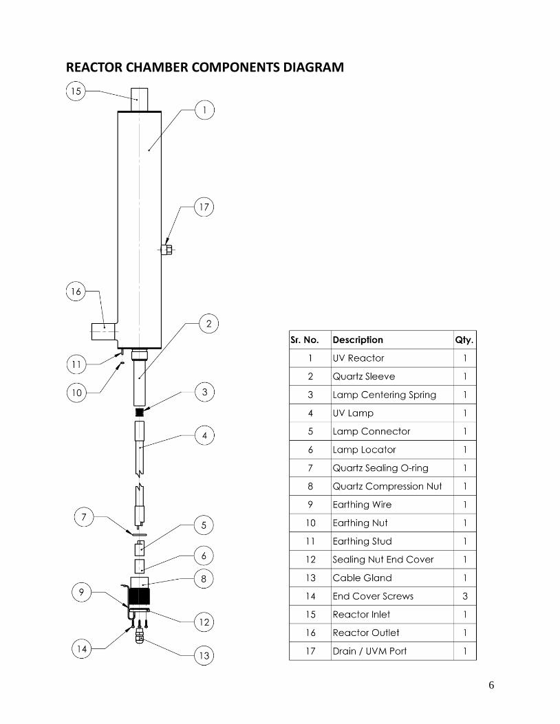
REACTOR CHAMBER COMPONENTS DIAGRAM

7
PRODUCT APPLICATION
Ultraviolet disinfection provides a simple, inexpensive way of destroying bacteria, mold, virus, algae and fungi without the use of heat or chemicals. Each EcoStream system is designed to achieve a specific energy dose to properly destroy microorganisms.
The dosage which applies to ultraviolet disinfection is proportional to energy, time, and area. The total UV energy is attributed to the amount of energy emitted from all sides of a UV lamp and is expressed in micro watts. The exposure is expressed in seconds and represents the total time it takes for the water to flow through the UV chamber. The final factor in determining the dosage relates to the total area and is expressed in centimeter squared. To summarize, the total dosage is expressed in µW-sec/cm2 or micro watt second per centimeter squared.
UV Disinfection is affected by many factors and the following should be looked at prior to the installation of the UV system:
1. UV Transmission (transmittance) deals with the effectiveness in which the 254 nanometer wavelength of ultraviolet light is transmitted through the water. The higher the transparency of the water, the more effective the UV system becomes. This optical clarity is evaluated by performing a test which passes incident light through a 1 cm depth of water and recording this against the same test using distilled water as a reference. This is done using a spectrophotometer.
The basic designs of the units have taken into account a typical transmission at the desired wavelength. In practical terms this means that a system designed to disinfect a flow of about 3 m3/hr (e.g. ECS60R) at a typical transmissibility (98%), could actually have a lower flow rate in liquids with a lower transmissibility. As a general guideline, the following are some typical UV transmission rates:
Deionized or reverse osmosis water : 90 - 98% Typical filtered fresh water : 90 - 94% Lakes, wells, or other private sources : 70 - 90% Other liquids (constituent dependant) : 0 - 95%
*** WARNING -- DO NOT UNDERSIZE UNITS ***
If exact transmission quality needs to be determined, have samples tested at a suitable lab using a proper spectrophotometer. Alternatively, you may contact Alfaa UV for a sample analysis.
2. Suspended Solids will act against a UV system by effectively shielding microorganisms from the ultraviolet light. Dirt, rust, turbidity, etc. all have the ability to block out the UV light. It is absolutely necessary to properly control the level of suspended solids by properly pre-filtering the liquid prior to disinfection (pre-filtration down to 5 micron is considered the minimum).
3. Total Dissolved Solids of around 500 ppm can drastically reduce the rated flow rate of the unit by absorbing UV energy. Proper pretreatment of high TDS levels must be taken into account.
8
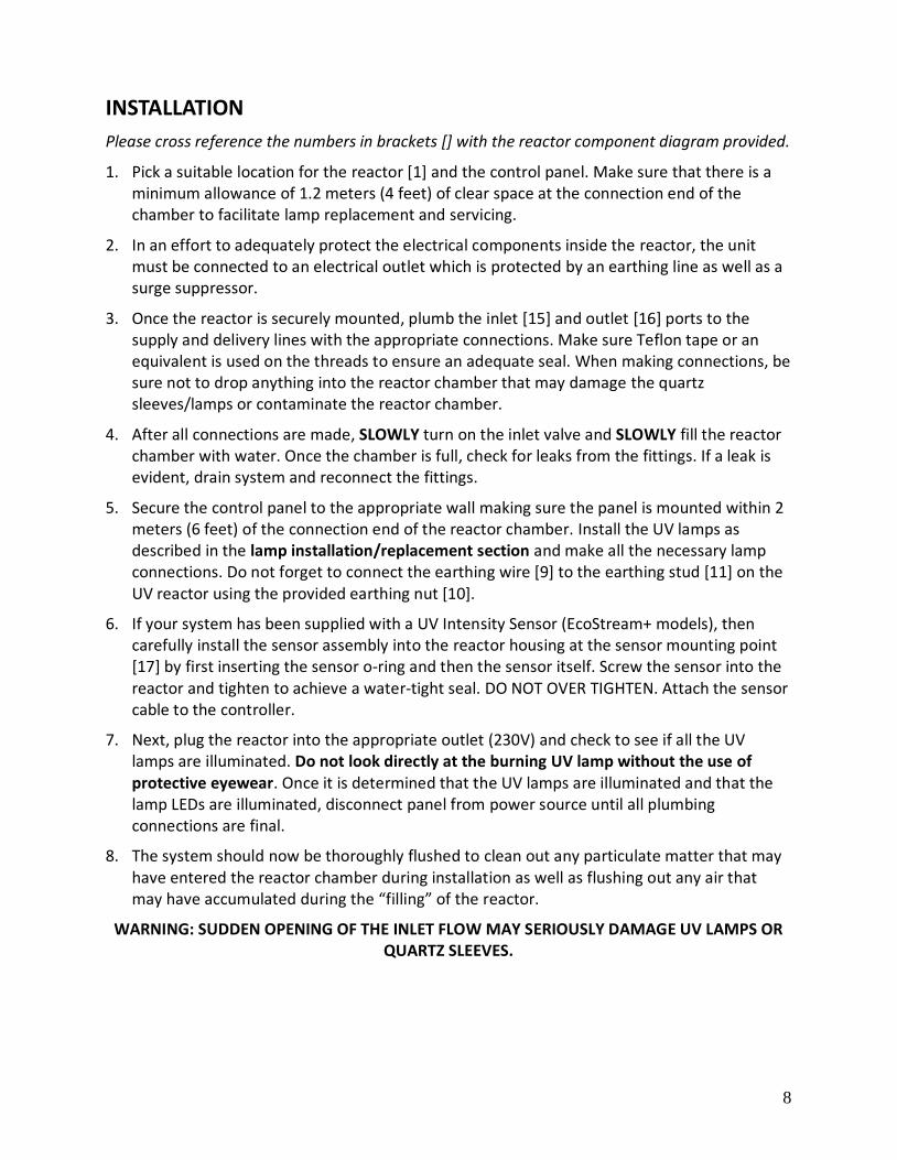
INSTALLATION
Please cross reference the numbers in brackets [] with the reactor component diagram provided.
1. Pick a suitable location for the reactor [1] and the control panel. Make sure that there is a minimum allowance of 1.2 meters (4 feet) of clear space at the connection end of the chamber to facilitate lamp replacement and servicing.
2. In an effort to adequately protect the electrical components inside the reactor, the unit must be connected to an electrical outlet which is protected by an earthing line as well as a surge suppressor.
3. Once the reactor is securely mounted, plumb the inlet [15] and outlet [16] ports to the supply and delivery lines with the appropriate connections. Make sure Teflon tape or an equivalent is used on the threads to ensure an adequate seal. When making connections, be sure not to drop anything into the reactor chamber that may damage the quartz sleeves/lamps or contaminate the reactor chamber.
4. After all connections are made, SLOWLY turn on the inlet valve and SLOWLY fill the reactor chamber with water. Once the chamber is full, check for leaks from the fittings. If a leak is evident, drain system and reconnect the fittings.
5. Secure the control panel to the appropriate wall making sure the panel is mounted within 2 meters (6 feet) of the connection end of the reactor chamber. Install the UV lamps as described in the lamp installation/replacement section and make all the necessary lamp connections. Do not forget to connect the earthing wire [9] to the earthing stud [11] on the UV reactor using the provided earthing nut [10].
6. If your system has been supplied with a UV Intensity Sensor (EcoStream+ models), then carefully install the sensor assembly into the reactor housing at the sensor mounting point [17] by first inserting the sensor o-ring and then the sensor itself. Screw the sensor into the reactor and tighten to achieve a water-tight seal. DO NOT OVER TIGHTEN. Attach the sensor cable to the controller.
7. Next, plug the reactor into the appropriate outlet (230V) and check to see if all the UV lamps are illuminated. Do not look directly at the burning UV lamp without the use of protective eyewear. Once it is determined that the UV lamps are illuminated and that the lamp LEDs are illuminated, disconnect panel from power source until all plumbing connections are final.
8. The system should now be thoroughly flushed to clean out any particulate matter that may have entered the reactor chamber during installation as well as flushing out any air that may have accumulated during the “filling” of the reactor.
WARNING: SUDDEN OPENING OF THE INLET FLOW MAY SERIOUSLY DAMAGE UV LAMPS OR QUARTZ SLEEVES.
9
UV Intensity Sensor Calibration Resetting
In case of a new installation or when the lamp is replaced with a new one, it is important to reset the sensor calibration settings. This must also be performed in case a new sensor is being fitted to the system.
Following is the procedure:
1. Ensure that the system and lamp is powered up and there is liquid flowing through the reactor.
2. Let the system run for at least 1 hour till it reached a steady state.
3. To reset the UV Intensity Sensor to 100%, press the Function key on the controller for 7 seconds.
4. Once confirmed, the controller will beep once and the screen will display 100%.
10
MAINTENANCE
The basic unit is designed to operate with minimal maintenance requirements providing the minimum water characteristics are met as are outlined in the section “Application Guidelines”. However there are two regular maintenance requirements common to all UV systems: cleaning and lamp replacement.
Cleaning
Minerals in the water will eventually coat the quartz sleeve (which protects the lamp), as well as the sensor (if the system is equipped with one). This coating must be cleaned off periodically because it reduces the amount of UV light reaching the water, thereby reducing disinfection performance.
Once a month, check the sleeve and clean it if you can see a mineral coating starting to form. If sleeve requires cleaning, refer to Lamp Replacement instructions but re-install the original lamp. If system is equipped with a sensor, be sure to also clean the sensor each time the sleeve is cleaned.
Quartz Sleeve Replacement/Cleaning
Please cross reference the numbers in brackets [] with the reactor component diagram provided.
5. If the lamp is in the system, remove the lamp and carefully set it aside as described in the lamp installation/replacement section.
6. Shut off the upstream water supply that feeds water into the reactor chamber. Depressurize and drain the system by disconnecting the inlet/outlet from the reactor chamber.
7. Unscrew and remove the QG sealing nut [8] from the top of the reactor. Make sure to remove the QG sealing O-ring [7] and keep it carefully.
8. Carefully slide the sleeve out of chamber. In case it is initially tight, gently try rotating the QG while also pulling it out. Also make sure that the sleeve is not at an angle as otherwise pressure will be applied on the sides of the sleeve and against the reactor chamber causing the sleeve to fracture.
9. Clean the quartz sleeve, or replace them with a new one. To clean the sleeve, use a mild acid solution such as 10% Citric Acid or household cleaners such as vinegar.
10. Reinstall the quartz sleeve in reverse order. Carefully slide the quartz sleeve into the reactor through the QG socket until it is locked into place in the internal QG holder. Ensure that the sleeve is inserted straight and not at an angle as doing so will put pressure on the wall of the sleeve and can cause it to crack. Install the quartz sealing o-ring [7] onto the sleeve until it rests against the QG socket.
11. Reinstall the QG socket compression nuts [8] by turning clockwise. This nut should be hand tightened only.
12. Slowly turn on the water and pressurize the reactor to verify that there are no leaks.

11
13. Reinstall the lamp as described in the lamp installation/replacement section and reconnect all the electrical connections to ensure that the system is operating properly.
UV Intensity Sensor Cleaning
9. Mineral deposits and sediment may accumulate on the sensor window decreasing the UV intensity detected. Good maintenance of pre-treatment equipment will reduce the accumulation of residues. If the system indicates that the UV intensity is low, one cause may be a stained quartz sleeve and/or sensor window. If necessary, remove the sensor assembly and proceed with cleaning process. Repeat the process as often as necessary to keep the sensor window and quartz sleeve clean.
10. Before removing the sensor assembly, follow the steps as outlined in the “Quartz Sleeve Replacement And/Or Cleaning” section. The quartz sleeve should be cleaned at the same time as the UV sensor. Disconnect the UV sensor from the EcoStream+ controller by disconnecting the sensor cable. To remove the sensor, grasp the stainless portion of the sensor and rotate counter-clockwise until the sensor is free of the threaded sensor port.
11. Once the sensor is free from the reactor chamber, clean the quartz window with a commercial scale remover or vinegar and a lint free cotton swab (ear bud). Do not use an abrasive cleaner on the sensor window. Scratching of the sensor window will void any manufacturer’s warranty on this item.
12. Carefully refit the sensor assembly into the reactor housing by first inserting the sensor o-ring and then the sensor itself. Screw the sensor into the reactor and tighten to achieve a water-tight seal. DO NOT OVER TIGHTEN. Attach the sensor cable to the controller and return to service.
Lamp Replacement
The UV lamp intensity decreases over time. The UV lamps used in the Alfaa EcoStream Models ECS60R – ECS150R are rated for approximately 9,000 hours of continuous use (approximately one year). The lamps used in models ECS250R and ECS310R are rated for 12,000 hours of continuous use. Replace the lamp after this time frame. The built in “Lamp Life Remaining” counter and “Replace Lamp” reminder aids in this task by continually monitoring the running time of the unit.
Lamp Installation/Replacement
Please cross reference the numbers in brackets [] with the reactor component diagram provided.
1. To replace the lamp, there is NO need to disconnect the system from the water supply, or to drain the water from the reactor chamber. Lamp replacement is easy requiring no special tools. The UV lamp must be replaced after 9,000 hours of continuous operation in order to ensure adequate disinfection.
2. Disconnect the main power source and allow the unit to power down. From the side where the lamp connections are made, disconnect the earthing wire [9] from the earthing stud [11] on the reactor and then unscrew the QG socket end cover screws [14].

12
3. Now gently pull out the lamp harness and extract the lamp connector [5] and UV lamp [4] from the UV reactor [1]. Once you can visually see the lamp, separate the lamp from the connector by pulling them apart. Do not try twisting the connector as it will break. While it is OK to touch the ceramic ends of the lamp, avoid touching the UV lamp “glass” with your fingers. Wipe off any oils with alcohol and a soft cloth. Warning: Depending on when the system was powered down the UV lamp might still be very hot. In this case please take care by using gloves or other protective gear.
4. Carefully remove the lamp from the reactor chamber taking special care not to angle the lamp as it is removed. If the lamp is removed at an angle, pressure will be applied on the inside of the quartz sleeve, causing the sleeve to fracture and break.
5. If the QG is going to be removed then also remove the lamp centering spring [3].
6. To install a new lamp, first remove the lamp from its protective packaging again being careful not to touch the lamp “glass” itself. Before inserting the lamp into the reactor vessel (actually inside the quartz sleeve) make sure that the lamp centering spring [3] is inserted into the quartz sleeve in the reactor. Now, insert the lamp fully into the chamber (with the pins on the connection side) leaving about two inches of the lamp protruding from the chamber.
7. Secure the lamp connector [5] on the UV lamp [4] ensuring that the connector is fully seated onto the pins. Finally, screw the socket cover [12] back onto the QG socket compression nut using the provided screws [14].
8. Connect the earthing wire [9] to the earthing stud [11] on the UV reactor using the provided earthing nut [10]. The system may now be powered up and tested.
9. Once a new lamp has been installed, please remember to recalibrate and reset the UV Intensity Sensor as per instructions provided in the UV Intensity Sensor Calibration Resetting section.

13
USING THE ECOSTREAM (BASIC) CONTROLLER
MODELS ECS60R / ECS100R / ECS150R WITHOUT UV INTENSITY SENSOR ONLY
The EcoStream controller incorporates a high performance electronic lamp controller along with a 5 digit seven segment LED display to update the user with the status of the UV system.
The controller also includes two soft-switches as follows:
1. Power
2. Function
Basic Operation
All EcoStream control boxes are equipped with a soft start on/off switch. When the main power to the system is turned on, the lamp will turn on directly. However, if required, the lamp can be turned off (and subsequently on) by using holding down the Power button on the EcoStream
Control box for 2 seconds. In this case the display will show on the screen indicating that the power to the lamp has been turned off.
Display Messages
1. (Default) When the system is in operation the standard display shows the “Lamp Life Remaining” in hours.
2. To see the total number of days the UV system has been in operation (across lamp changes), then press the Function key once. The display will switch to this information. Wait for 10 seconds for the display to default back to the main screen again.
3. In case of a situation where the lamp life is over, the screen will show the message and the buzzer will also beep intermittently.
4. Once a new lamp has been installed, to reset the Lamp Life Counter, keep the Power and Function buttons pressed at the same time for 10 seconds. This will reset the Lamp Life Counter back to 9000 hours and remove the alarm message.
5. In case of lamp failure, the display will show the message . The buzzer will also sound continuously. In this case turn the system off immediately and check the lamp condition. Replace the lamp with a new one if required by following the instructions in the Lamp Replacement section.
Power
Function
Display
Lamp Cable

14
USING THE ECOSTREAM+ CONTROLLER
MODELS ECS60R+ / ECS100R+ / ECS150R+ / ECS250R+ / ECS310R+ WITH INCLUDED UV INTENSITY SENSOR ONLY
The EcoStream+ controller incorporates a high performance electronic lamp controller along with a 5 digit seven segment LED display to update the user with the status of the UV system. In addition to this the EcoStream+ models also incorporate a UV sensor which detects the specific 254 nm wavelength of the UV lamp. This information is relayed to the controller and the UV intensity level is displayed by default on the controller in “% UV Output”.
Controller Layout: ECS60R / ECS100R / ECS150R
The controller includes two soft-switches as follows:
1. Power
2. Function
Controller Layout: ECS250R / ECS310R
The controller also includes two soft-switches as follows:
1. Power
2. Function
Power
Function
Display (Default shows UV Intensity in %)
Sensor Cable
Lamp Cable
Power
Function
Display (Default shows UV Intensity in %)
15
Basic Operation
All EcoStream control boxes are equipped with a soft start on/off switch. When the main power to the system is turned on, the lamp will turn on directly. However, if required, the lamp can be turned off (and subsequently on) by using holding down the Power button on the EcoStream
Control box for 2 seconds. In this case the display will show on the screen indicating that the power to the lamp has been turned off.
The controller by default will display the UV output between 0 to 99 percent.
Note: The low UV alarm will not activate for the first 180 seconds of the system being switched on which is the warm up period of the lamp.
Display Messages
1. (Default) When the system is in operation the standard display shows the UV Intensity from the lamp in percentage.
2. To see the “Lamp Life Remaining” in hours, press the Function key once. The display will switch to this information. Wait for 10 seconds for the display to default back to the main screen again.
3. To see the total number of days the UV system has been in operation (across lamp changes), then press the Function key again (while the screen is in the “Lamp Life Remaining” screen). The display will switch to this information. Wait for 10 seconds for the display to default back to the main screen again.
4. When the system drops below 50%, a low UV warning is displayed as “LI” and alternately flashes (at 2 second intervals) back to the actual UV level.
Example: <- 2 seconds -> Additionally, the system will supply an intermittent audible tone (2 seconds on, 2 seconds off), during low UV conditions.
5. In case of a situation where the lamp life is over, the screen will show the message and the buzzer will also beep intermittently.
6. Once a new lamp has been installed, to reset the Lamp Life Counter, keep the Power and Function buttons pressed at the same time for 10 seconds. This will reset the Lamp Life Counter back to 9000 hours and remove the alarm message.
7. In case of lamp failure, the display will show the message . The buzzer will also sound continuously. In this case turn the system off immediately and check the lamp condition. Replace the lamp with a new one if required by following the instructions in the Lamp Replacement section.

16
UV Intensity Levels
The following are the UV Intensity levels and they implications:
to Indicates the system is functioning within normal a normal operating range
to
Indicates the UV level is still within a safe level, however at this level the system should be examined to determine why the UV level is this low.
to
Indicates the UV level is nearing the point of unsafe UV intensity, at this level the system should be closely examined to determine why the UV level is this low.
<
Indicates the UV level has now reached a level that is unsafe. At this level the water should not be consumed. The system/water supply should be examined to determine the reason for the low UV level of the UV intensity.
At this level, the system will flash a low
intensity message on the display alternating with the actual UV intensity percentage.

17
WARRANTY
If, within 12 months from the date of original purchase, any component or any part of the Alfaa UV system covered by this Warranty proves to be defective in material or workmanship, Ace Hygiene Products Private Limited will at its discretion replace, repair or rectify the equipment.
Terms and Conditions of Warranty:
1. Usage must be in accordance with the instructions in the Operating Manual. The Warranty does not cover wrong application of the equipment over and above the specified flow rates, pressure and electrical ratings.
2. Consumable components such as ultraviolet lamp are not covered by this warranty.
3. The Warranty shall immediately cease and become full and void if unauthorized repairs, alteration or modification is made to be product.
4. The serial number must not be defaced or altered in any way.
5. The Warranty extended herein is in lieu of all implied conditions and warranties under the law and is confined to the repair or replacement of defective parts and does not cover any direct or consequential damage/loss caused due to failure of the product.
6. In case of any defect/malfunctioning of the equipment it shall be intimated to us in writing and only after our content in writing the equipment may be sent back for rectification. The equipment shall be returned by the purchaser in securely packed condition and on freight paid basis.
7. Subject to Mumbai Jurisdiction.
MODEL NUMBER: ____________________
SERIAL NUMBER: ____________________
INVOICE NUMBER: ____________________
For ACE HYGIENE PRODUCTS PVT. LTD.,
AUTHORISED SIGNATORY

18
Notes: