Economical ICF to cold-formed steel floor connections · ECONOMICAL L ICF F TO O ... (Specimen 7)...
28
U.S. Department of Housing and Urban Development Office of Policy Development and Research E E C C O O N N O O M M I I C C A A L L I I C C F F T T O O C C O O L L D D - - F F O O R R M M E E D D S S T T E E E E L L F F L L O O O O R R C C O O N N N N E E C C T T I I O O N N S S
-
Upload
nguyendung -
Category
Documents
-
view
216 -
download
0
Transcript of Economical ICF to cold-formed steel floor connections · ECONOMICAL L ICF F TO O ... (Specimen 7)...

U.S. Department of Housing and Urban DevelopmentOffice of Policy Development and Research
EECCOONNOOMMIICCAALL IICCFF TTOO CCOOLLDD--FFOORRMMEEDD SSTTEEEELL FFLLOOOORR CCOONNNNEECCTTIIOONNSS
PATH (Partnership for Advanced Technology in Housing) is a new private/public effort to develop, demonstrate,and gain widespread market acceptance for the “Next Generation” of American housing. Through the use of new orinnovative technologies the goal of PATH is to improve the quality, durability, environmental efficiency, andaffordability of tomorrow’s homes.
PATH, initiated jointly by the Administration and Congress, is managed and supported by the Department ofHousing and Urban Development (HUD). In addition, all Federal Agencies that engage in housing research andtechnology development are PATH Partners, including the Departments of Energy and Commerce, as well as theEnvironmental Protection Agency (EPA) and the Federal Emergency Management Agency (FEMA). State and localgovernments and other participants from the public sector are also partners in PATH. Product manufacturers, homebuilders, insurance companies, and lenders represent private industry in the PATH Partnership.
To learn more about PATH, please contact:
451 7th Street, SWSuite B 133Washington, DC 20410202-708-5873 (fax)e-mail: [email protected] website: www.pathnet.org
Visit PD&R's Web Sitewww.huduser.org to find this report and others sponsored byHUD's Office of Policy Development and Research (PD&R).
Other services of HUD USER, PD&R's Research Information Service, include listservs; special interest, bimonthlypublications (best practices, significant studies from other sources); access to public use databases; hotline1-800-245-2691 for help accessing the information you need.

ECONOMICAL ICF TOCOLD-FORMED STEELFLOOR CONNECTIONS
ECONOMICAL ICF TOCOLD-FORMED STEELFLOOR CONNECTIONS
Prepared for
The U.S. Department of Housing and Urban DevelopmentOffice of Policy Development and ResearchWashington, DC
by
NAHB Research Center, Inc.400 Prince George's BoulevardUpper Marlboro, MD 20774-8731
Contract No. C-OPC-21289
May 2001
Disclaimer
While the information in this document is believed to be accurate, neither the authors, nor reviewers, nor the U.S. Department of Housing and Urban Development of the U.S. Government, nor the NAHB Research Center, Inc., nor any of their employees or representatives makes any warranty, guarantee, or representation, expressed or implied, with respect to the accuracy, effectiveness, or usefulness of any information, method, or material in this document, nor assumes any liability for the use of any information, methods, or materials disclosed herein, or for damages arising from such use.
The contents of this report are the views of the contractor and do not necessarily reflect the views or policies of the U.S. Department of Housing and Urban Development or the U.S. Government.
ii

ACKNOWLEDGEMENTS
This report was prepared by the NAHB Research Center, Inc., under sponsorship of the U.S. Department of Housing and Urban Development (HUD). Special appreciation is extended to Marie Del Bianco of the Research Center and Chad Garner of Bruce Davis Construction, Inc., for their insight. Review and comments provided by William Freeborne and Andrea Vrankar of HUD are also appreciated.
iii

iv

EXECUTIVE SUMMARY
During a Partnership for Advanced Technology in Housing (PATH) demonstration project using Insulated Concrete Form (ICF) systems, the builder requested technical support regarding the connection of cold-formed steel (CFS) floor systems and ICF walls. An initial investigation determined that existing construction guidelines and practices for this connection are limited in scope and inefficient in labor and material usage. To address this problem, two fastening methods were identified and tested in the interest of optimizing the connection of CFS floor systems to ICF walls.
The ARXX (formerly Blue Maxx) ICF system and Deitrich CFS "Trade-Ready" floor system were used for this study to match the products being used or planned for use in the PATH demonstration project. The connection methods addressed in this report use a "Richmond F-32" anchor (16 gauge rock tie) or a 5/8-inch diameter anchor bolt (J-bolt) to transmit floor loads from a steel rim track (16 gauge), through an ICF insulation layer, and into an ICF concrete core.
The results of this study are summarized as follows:
• Richmond F-32 anchors and 5/8-inch diameter anchor bolts are appropriate for structural connection of ICF walls to CFS floors;
• the Richmond F-32 anchors offer an estimated cost reduction of about $1.40 per lineal foot of floor connection when compared to existing practice using anchor bolts and form "cut-outs" as with a wood floor system and ledger;
• an allowable design strength of 500 lbs/anchor is recommended for the Richmond F-32 anchors;
• an allowable design strength of 670 lbs/anchor is recommended for 5/8-inch diameter anchor bolts; and,
• the Richmond F-32 anchor and 5/8-inch diameter anchor bolts should be installed according to the table below.
FLOOR CLEAR SPAN MAXIMUM ANCHOR SPACING (INCHES) RICHMOND F-32 ANCHOR 5/8-INCH DIAMETER ANCHOR BOLT
<10 ft 24 24 11 ft 22 24 12 ft 20 24 13 ft 18 22 14 ft 17 21 15 ft 16 20 16 ft 15 18 17 ft 14 17 18 ft 13 16 19 ft 12 15 20 ft 12 15
NOTES:(1)Anchors shall be 5/8-inch diameter anchor bolt or Richmond F-32 anchor (minimum 16 ga).(2)Steel floor track (ledger) thickness shall be a minimum 16 ga.(3)Anchors shall be spaced no closer than 1 foot apart.(4)Concrete wall nominal thickness shall be a minimum of 6 inches.(5)Anchor embedment shall be a minimum of 5 inches in concrete with no more than a 2.5 inch cantilever extension through theICF insulation.(6)A minimum of four (4) #8 self-drilling tapping screws shall connect the steel track to the Richmond F-32 anchor face and thescrews shall be placed no less than 1 inch apart in each anchor.(7)A 40 psf floor live load and a 10 psf dead load is assumed.(8)Minimum concrete f'c = 2,500 psi.
v

vi

TABLE OF CONTENTS
Page
ACKNOWLEDGEMENTS........................................................................................................... iii
EXECUTIVE SUMMARY ............................................................................................................ v
INTRODUCTION .......................................................................................................................... 1
BACKGROUND ............................................................................................................................ 1
APPROACH ................................................................................................................................... 3
RESULTS ....................................................................................................................................... 5
CONCLUSIONS........................................................................................................................... 10
REFERENCES ............................................................................................................................. 10
APPENDIX A - FAILURE MODE PREDICTIONS FOR THE RICHMOND F-32 ANCHOR
APPENDIX B - DETERMINATION OF SAFETY AND RESISTANCE FACTORS
vii

LIST OF TABLES
Page
Table 1 Estimated Design Strength of Richmond F-32 Anchor Connection........................5Table 2 Test Results for Richmond F-32 Anchors (Specimens 1 through 5) .......................6Table 3 Test Results for Richmond F-32 Anchors (Specimens 6 through 10) .....................6Table 4 Test Results for 5/8-Inch Diameter Anchor Bolts ...................................................7Table 5 Steel Floor to ICF Wall Connection Requirements .................................................9Table 6 Cost Comparison....................................................................................................10
LIST OF FIGURES
Page
Figure 1 Conventional Floor Attachment...............................................................................1Figure 2 Richmond F-32 Connection.....................................................................................2Figure 3 Richmond F-32 Stone Anchor .................................................................................2Figure 4 Photograph of Test Set-Up.......................................................................................3Figure 5 Concrete Filled Specimens ......................................................................................4Figure 6 Bending (Specimen 7) and Torsion (Specimen 6) Failure Modes...........................8
viii

INTRODUCTION
The use of insulating concrete forms (ICF) in combination with cold-formed steel (CFS) framing is relatively new to the U.S. homebuilding industry. Unfortunately, published information provides little guidance regarding "best practices". This problem was identified by Bruce Davis Homes during construction of a Partnership for the Advancement of Technology in Housing (PATH) demonstration project at Washington Square, LaPlata, Maryland. In considering the use of a CFS floor system with a side-bearing connection to ICF walls, it was found that existing construction guidelines did not address this connection detail in a manner applicable to or efficient for ICF and CFS materials [1][2]. Therefore, two fastening methods were identified based on their potential to improve the constructability and economy of ICF wall to CFS floor connections. This study investigates and reports the performance of such connections using standard 5/8-inch diameter anchor bolts or Richmond F-32 anchors to transmit the floor load from a steel ledger track, through the ICF foam insulation, and into the concrete core of an ICF wall.
BACKGROUND
The conventional method for attaching ICFs to wood floors is shown in Figure 1. When using this method, the ICF insulation is cut out at the anchor bolt locations and a surface wood form is used to contain the concrete during casting. The wood ledger is then attached to the ICF wall by drilling to match J-bolt (anchor bolt) locations. Thus, several time-consuming steps are required in the construction sequence.
Figure 1 Conventional Floor Attachment
The trial connection method uses a Richmond F-32 anchor as shown in Figure 2. The anchor is an L-shaped 16-gauge piece of galvanized steel with a 2 in x 2 in face and a 2 in x 8 in corrugated tail embedded in the concrete. The corrugations allow the embedded steel to develop significant withdrawal strength and activate a larger area in the concrete for improved bearing strength.
1

Figure 2Richmond F-32 Stone Anchor
The connection assembly using a Richmond F-32 anchor is shown in Figure 3. The Richmond F-32 anchor is simply inserted through the ICF foam adjacent to a plastic form tie. One #8 screw through the anchor face into the ICF plastic cross-tie on the outside of the form is used to hold the anchor firmly in place until the concrete is cast. Once the concrete is placed and cured, a steel floor track (ledger) is attached to the face of each embedded Richmond F-32 anchor using a minimum of four (4) #8 self-drilling tapping screws. The metal track is easily leveled when screwed to the anchors. A 5/8-inch diameter anchor bolt may be inserted through the ICF in a similar manner, but this method still requires careful drilling of the steel track as with the wood ledger approach described above. A potential downfall of the Richmond F-32 anchor approach is that the ledger connection is a "blind connection" (i.e., the installer cannot see the anchor once the ledger is in place which may increase the likelihood of missed fasteners).
Figure 3Richmond F-32 Anchor Installed in an ICF Form
(face of anchor is flush with outside of form).
2

The investigation reported herein focuses on the structural performance, such as ultimate capacity, of each connection method. The Richmond F-32 anchor acts as a shear tab transmitting the gravity loads from the floor track through the non-structural foam into the concrete. Since the Richmond F-32 anchor is a 16-gauge steel tab two inches in depth, it has significant stiffness in one direction only. Thus, the floor system should be attached to walls on at least three sides to prevent sideways movement of the floor and constrain motion about the anchor’s weak axis. Conversely, the 5/8-inch diameter anchor bolt acts as a cantilevered steel rod, has equal stiffness in all directions, and is not required to be constrained against sideways movement.
APPROACH
TEST METHODS
The connection test procedure followed ASTM E488-96 Standard Test Methods for Strength of Anchors in Concrete and Masonry Elements [3]. The displacement-controlled loading rate was set at the standard specified 0.2 in/min. All tests were completed using a 200,000 lb universal testing machine (Southwark-Emery Model 78075), a Satek Epsilon Series 2 inch deflectometer, and a Newvision II Data Acquisition System. The deflectometer measured the movement of the UTM and therefore, includes deflection (slack) of the test jig, bearing compression of the CFS floor joists at UTM and reaction points, and the actual joint slip.
The loading jig deviated from ASTM E488 to accommodate the unique ICF wall and CFS floor connection specimens. The loading jig allowed the specimen to be tested in a manner representing actual construction and loading conditions that would be experienced in the field. The test jig also prevented sideways movement of the CFS floor relative to the ICF wall. This type of motion is generally prevented in actual floor systems by attachment to walls on more than two sides of the floor platform. The loading jig and a test specimen are shown in Figure 4.
Figure 4Photograph of Test Set-Up
3

The load was applied to each specimen through a 1-1/2 inch diameter steel roller spaced 3 inches from inside the face of the ICF wall segment and was reacted through the Richmond F-32 anchor (or 5/8-inch diameter anchor bolt) and another roller support 16 inches away from the face of the ICF wall segment at the base of the CFS floor segment. By applying basic statics, the shear load placed on the anchor connection was 13/16 of the total applied load.
SPECIMEN CONSTRUCTION
Three ICF test specimens (see Figure 5) were constructed using ARXX 8-inch-thick ICF forms, 2,500 psi design strength concrete mix with 3/8 inch aggregate, #4 rebars, and Richmond F-32 concrete anchors or 5/8-inch diameter anchor bolts. The specimens were allowed to cure a minimum of 28 days prior to testing. The concrete was mixed by hand in two 1/6-yd3 batches. From 6-inch diameter cylinders, the actual 28-day concrete strength (f’c) was 1,800 psi and 3,300 psi for the two batches.
Figure 5 Concrete Filled Specimens
One ICF wall segment contained five Richmond F-32 anchor specimens with a #4 rebar placed directly below the anchors (Specimens 1-5). The second ICF wall segment also contained five Richmond F-32 anchor specimens (Specimens 6-10), but the #4 rebar was placed outside of the anticipated failure zone below the anchors. A third ICF wall segment was constructed to evaluate the group effect of four F-32 anchors (Specimens 11 and 12) for use as a beam pocket replacement or similar applications requiring support of heavy concentrated loads. Three 5/8-inch diameter headed all-thread bolt specimens (Rods 1-3) were also included in the third ICF wall segment. The third ICF wall segment included rebar in the lower bearing zone of the anchors.
4

Due to the manner of "punching" the Richmond F-32 anchors through the ICF foam, a conical piece of ICF was dislodged on the inside of the form. This condition allowed the concrete to flow out toward the ICF face which provided some additional support to the Richmond F-32 anchors. Thus, the unsupported length of the Richmond F-32 anchors was less than the ICF foam thickness of 2 inches. The removed cone of ICF form material (insulation) may reduce the strength of the forms. However, the potential affect on form strength was not a subject of concern in this study. As an alternative installation approach, a hot knife or key-hole saw may be used to cut a slot in the ICF insulation for the Richmond F-32 anchor.
FAILURE MODE PREDICTIONS
Possible failure modes of the connection assembly using the Richmond F-32 anchor were investigated prior to specimen fabrication and testing to better understand the expected structural behavior of the connection. Failure modes considered include concrete bearing failure, concrete pullout failure, anchor bending failure, anchor shear failure, anchor torsion failure, and screw attachment failure. Comparison of the design capacity of the joint (for each failure mode) resulted in the values shown in Table 1; calculations are included in Appendix A using appropriate material design specifications [4][5][6]. The probable connection failure modes include concrete bearing, anchor bending, and screw shear. Assuming these calculations reasonably predict the connection performance, a design value of between 300 lb to 600 lb was considered as a "target" range.
TABLE 1ESTIMATED DESIGN STRENGTH OF RICHMOND F-32 ANCHOR CONNECTION
FAILURE MODE CALCULATED DESIGN STRENGTH PER ANCHOR Concrete Bearing Strength
Based on steel thickness 481 lb Based on effective width 1,785 lb
Concrete Pull Out 17,170 lb Bending Failure
with rotation 288 lb without rotation 576 lb
Shear 1,426 lb Torsion Functional Limit, Four Fasteners per Anchor required
Screws (4 per anchor) 1,493 lb (without torsion) 667 lb (with torsion)
RESULTS
TEST DATA
The results for all of the tests are reported as the maximum test load of the ICF wall to CFS floor connection, including adjustment for the loading geometry of the test jig (i.e., the UTM load is multiplied by 13/16). Stiffness of the connection is not reported since the deflection measured was the total deflection due to the transfer of the applied load through the specimen and test jig. In addition, the maximum test load does not always represent the actual ultimate capacity of the connection due to maximum specimen deflection limitation imposed by the test jig. Therefore, the maximum test load is a conservative definition of the characteristic (unfactored) ultimate connection strength. This definition of characteristic strength also has the effect of placing a
5

functional limit on the deflection of the connection since the maximum test load tended to occur at a joint deflection of about 0.25 inches or slightly more (based on inspection of the load-deflection plots and the anchors after testing). As expected, none of the specimens experienced a brittle failure.
Table 2 gives the results for Richmond F-32 anchor specimens 1 through 5. The specimens included rebar in the concrete failure zone below the anchor. The measured f'c of the concrete was 1,800 psi.
TABLE 2TEST RESULTS FOR RICHMOND F-32 ANCHORS
(SPECIMENS 1 THROUGH 5)
SPECIMEN MAXIMUM TEST LOAD AT CONNECTION JOINT
(lb) 1 1,740 2 1,360 3 1,370 4 1,440 5 1,390
Average 1,460 COV 0.11
Table 3 gives the results for Richmond F-32 anchors 6 through 10. These anchors did not have rebar in the concrete failure zone below the anchor. The measured f'c of the concrete was 3,300 psi.
TABLE 3TEST RESULTS FOR RICHMOND F-32 ANCHORS
(SPECIMENS 6 THROUGH 10) SPECIMEN MAXIMUM TEST LOAD AT
CONNECTION JOINT (lb) 6 8401
7 2,5702
8 1,760 9 1,381
10 1,580 Average 1,626 COV 0.39 1Only two of four #8 screws engaged the Richmond F-32 anchor. 2Abnormally high value may be the result of specimen interference with the test jig.
Table 4 gives the results for the headed grade five anchor bolts (5/8-inch diameter threaded rod with a nut at the embedded end) inserted directly through the ICF face and embedded in the concrete core a minimum of 5 inches. These tests were conducted with rebar in the concrete failure zone below the anchor. The measured f'c of the concrete was 1,800 psi.
6
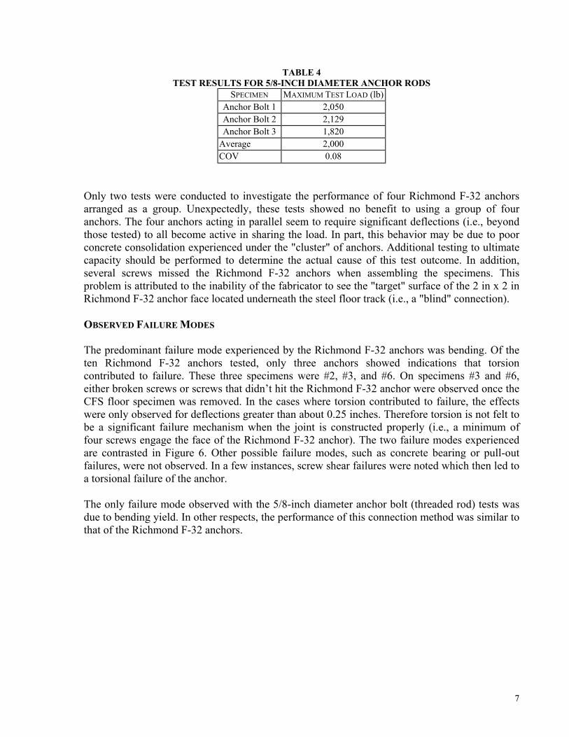
TABLE 4TEST RESULTS FOR 5/8-INCH DIAMETER ANCHOR RODS
SPECIMEN MAXIMUM TEST LOAD (lb) Anchor Bolt 1 2,050 Anchor Bolt 2 2,129 Anchor Bolt 3 1,820
Average 2,000 COV 0.08
Only two tests were conducted to investigate the performance of four Richmond F-32 anchors arranged as a group. Unexpectedly, these tests showed no benefit to using a group of four anchors. The four anchors acting in parallel seem to require significant deflections (i.e., beyond those tested) to all become active in sharing the load. In part, this behavior may be due to poor concrete consolidation experienced under the "cluster" of anchors. Additional testing to ultimate capacity should be performed to determine the actual cause of this test outcome. In addition, several screws missed the Richmond F-32 anchors when assembling the specimens. This problem is attributed to the inability of the fabricator to see the "target" surface of the 2 in x 2 in Richmond F-32 anchor face located underneath the steel floor track (i.e., a "blind" connection).
OBSERVED FAILURE MODES
The predominant failure mode experienced by the Richmond F-32 anchors was bending. Of the ten Richmond F-32 anchors tested, only three anchors showed indications that torsion contributed to failure. These three specimens were #2, #3, and #6. On specimens #3 and #6, either broken screws or screws that didn’t hit the Richmond F-32 anchor were observed once the CFS floor specimen was removed. In the cases where torsion contributed to failure, the effects were only observed for deflections greater than about 0.25 inches. Therefore torsion is not felt to be a significant failure mechanism when the joint is constructed properly (i.e., a minimum of four screws engage the face of the Richmond F-32 anchor). The two failure modes experienced are contrasted in Figure 6. Other possible failure modes, such as concrete bearing or pull-out failures, were not observed. In a few instances, screw shear failures were noted which then led to a torsional failure of the anchor.
The only failure mode observed with the 5/8-inch diameter anchor bolt (threaded rod) tests was due to bending yield. In other respects, the performance of this connection method was similar to that of the Richmond F-32 anchors.
7

Figure 6Bending (Specimen 7) And Torsion (Specimen 6) Failure Modes
DESIGN VALUES
The performance of Richmond F-32 anchors 1 through 5 was similar to anchors 6 through 10 even though differences existed between the two groups with respect to (1) concrete strength in the range of 1,800 to 3,300 psi and (2) placement of rebar within or outside the anticipated zone of concrete failure around the connection. Based on this observation, the ten Richmond F-32 anchor tests were treated as one group for the purpose of developing design values. Furthermore, test specimens 6 and 7 were removed from the data set. In one case, two screws were missing from the connection (Specimen 6). In the other case (Specimen 7), the measured maximum test load was abnormally high due to suspected interference with the test jig or non-typical specimen assembly conditions.
Based on the analysis of safety factors in Appendix B and the reported maximum test load data, the following allowable strength design (ASD) values are recommended:
• Richmond F-32 Anchor = 500 lbs • 5/8-inch diameter anchor bolt = 670 lbs
A safety factor of 3.0 was used in both cases. For the LRFD design method a resistance factor of 0.5 should be used with the following characteristic strength values based on the average of maximum tested loads:
• Richmond F-32 anchor characteristic strength = 1,500 lb • 5/8-inch diameter anchor bolt characteristic strength = 2,000 lb
Using the experimentally determined design values, prescriptive connection requirements were determined as shown in Table 5. The tabulated requirements were calculated by setting the connection's design strength value equal to the design floor load multiplied by the tributary floor area.
8

TABLE 5STEEL FLOOR TO ICF WALL CONNECTION REQUIREMENTS
FLOOR CLEAR SPAN MAXIMUM ANCHOR SPACING (INCHES)
RICHMOND F-32 ANCHOR 5/8-INCH DIAMETER ANCHOR
BOLT <10 ft 24 24 11 ft 22 24 12 ft 20 24 13 ft 18 22 14 ft 17 21 15 ft 16 20 16 ft 15 18 17 ft 14 17 18 ft 13 16 19 ft 12 15 20 ft 12 15
NOTES:(1)Anchors shall be 5/8-inch diameter anchor bolt or Richmond F-32 anchor (minimum 16 ga).(2)Steel floor track (ledger) thickness shall be a minimum 16 ga.(3)Anchors shall be spaced no closer than 1 foot apart.(4)Concrete wall nominal thickness shall be a minimum of 6 inches.(5)Anchor embedment shall be a minimum of 5 inches in concrete with no more than a 2.5 inch cantilever extensionthrough the ICF insulation.(6)A minimum of four (4) #8 self-drilling tapping screws shall connect the steel track to the Richmond F-32 anchorface and the screws shall be placed no less than 1 inch apart in each anchor.(7)A 40 psf floor live loads and 10 psf dead load is assumed.(8)Minimum concrete f'c = 2,500 psi.
PROJECTED COST SAVINGS
Projected costs for the ICF wall to CFS steel floor attachment were estimated using RS Means cost data and estimates [7]. The analysis compares conventional 1/2-inch diameter anchor bolts with concrete bearing surface (i.e., cut-outs in the ICF form) to the application of Richmond F-32 anchors. Only material and labor costs are considered since overhead and profit are company specific. The comparison is based only on costs up to the point of attaching the rim track. The method using 5/8-inch diameter anchor bolts cantilevering through the ICF insulation is not addressed, though costs should be similar to the method using Richmond F-32 anchors. The following assumptions are made for the conventional anchor bolts and the Richmond F-32 connection.
Conventional Method:
• 1/2" x 8" anchor bolts (J-bolts) are spaced at 24 inches on center; • ICF foam is removed at ledger (6 inch strip) for bearing; and • ledger area formed using plyform with four re-uses.
Richmond F-32 Connection:
• Richmond F-32 anchors are spaced at 12 inches on center; and • installation rate of 20 anchors per hour.
9

Using RS Means cost data [7] and the above assumptions, comparative costs were estimated as reported in Table 6. The cost savings for the method using Richmond F-32 anchors was estimated at $1.40 per lineal foot of floor ledger.
TABLE 6COST COMPARISON
CONVENTIONAL METHOD MATERIAL $/ft LABOR $/ft TOTAL $/ft Remove Inside Foam Form 0.01 0.25 0.26 Form Ledger Face 0.38 3.65 4.03 Anchor Bolt 0.26 0.55 0.81
Total 0.64 4.45 5.10 RICHMOND F-32 CONNECTION METHOD
Insertion and Attachment of F-32 1.41 2.29 3.70
CONCLUSIONS
The following conclusions are supported by this study:
• Richmond F-32 anchors (rock ties) and 5/8-inch diameter anchor bolts are appropriate for structural ICF wall to CFS floor connections.
• Installation should closely follow the guidelines of Table 5 and care should be taken to ensure that all fasteners are correctly installed.
• Richmond F-32 anchors offer an estimated cost reduction of about $1.40 per lineal foot of floor connection as compared to conventional practice.
• Bending failure of the anchors best represents the experimentally observed failure modes. • For allowable stress design (ASD), a safety factor of 3 and an allowable design strength of
500 lb is recommended for the Richmond F-32 anchor; a safety factor of 3 and an allowable design strength of 670 lb is recommended for 5/8-inch diameter anchor bolts.
• For load and resistance factor design (LRFD) or strength design, a resistance factor of 0.5 and a characteristic design strength of 1,500 lb is recommended for the Richmond F-32 anchor; a resistance factor of 0.5 and a characteristic design strength of 2,000 lb is recommended for 5/8-inch diameter anchor bolts.
REFERENCES
[1] Prescriptive Method for Residential Cold-Formed Steel Framing, Third Edition, NAHB Research Center, Inc., Upper Marlboro, MD, 1998.
[2] Prescriptive Method for Insulating Concrete Forms in Residential Construction, U.S. Department of Housing and Urban Development, Washington, DC, 1998.
[3] ASTM E488-96, Standard Test Methods for Strength of Anchors in Concrete and Masonry Elements, American Society of Testing and Materials (ASTM), West Conshohocken, PA, 1996.
[4] Building Code Requirements for Structural Concrete, ACI 318, American Concrete Institute (ACI), Farmington Hills, MI, 1999.
10
[5] Load and Resistance Factor Design, Volume 1, Second Edition, American Institute of Steel Construction (AISC), Chicago, IL, 1995.
[6] Cold Formed Steel Design Manual, American Iron and Steel Institute, Milwaukee, WI, 1997.
[7] RS Means Repair and Remodeling 1999 Cost Data, RS Means Company, Kingston, MA, 1999.
11

12
APPENDIX AFAILURE MODE PREDICTIONS
FOR THE RICHMOND F-32 ANCHOR
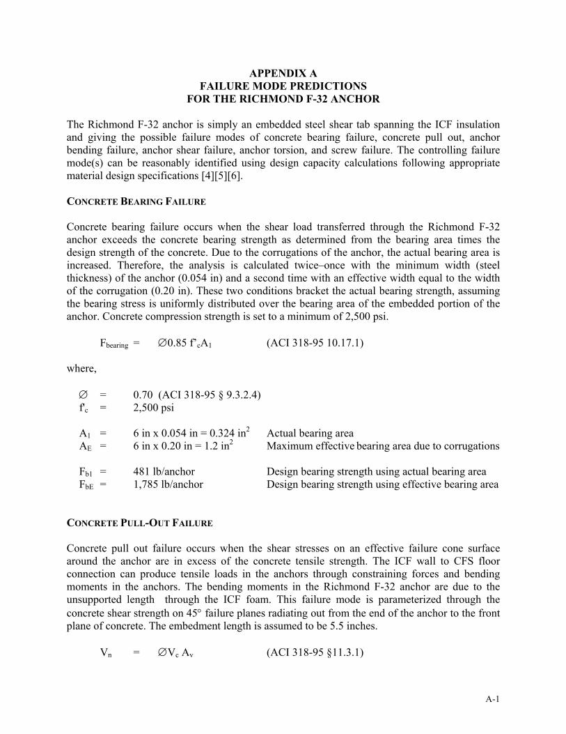
The Richmond F-32 anchor is simply an embedded steel shear tab spanning the ICF insulation and giving the possible failure modes of concrete bearing failure, concrete pull out, anchor bending failure, anchor shear failure, anchor torsion, and screw failure. The controlling failure mode(s) can be reasonably identified using design capacity calculations following appropriate material design specifications [4][5][6].
CONCRETE BEARING FAILURE
Concrete bearing failure occurs when the shear load transferred through the Richmond F-32 anchor exceeds the concrete bearing strength as determined from the bearing area times the design strength of the concrete. Due to the corrugations of the anchor, the actual bearing area is increased. Therefore, the analysis is calculated twice–once with the minimum width (steel thickness) of the anchor (0.054 in) and a second time with an effective width equal to the width of the corrugation (0.20 in). These two conditions bracket the actual bearing strength, assuming the bearing stress is uniformly distributed over the bearing area of the embedded portion of the anchor. Concrete compression strength is set to a minimum of 2,500 psi.
Fbearing = ∅0.85 f’cA1 (ACI 318-95 10.17.1)
where,
∅ = 0.70 (ACI 318-95 § 9.3.2.4) f'c = 2,500 psi
A1 = 6 in x 0.054 in = 0.324 in2 Actual bearing areaAE = 6 in x 0.20 in = 1.2 in2 Maximum effective bearing area due to corrugations
Fb1 = 481 lb/anchor Design bearing strength using actual bearing areaFbE = 1,785 lb/anchor Design bearing strength using effective bearing area
CONCRETE PULL-OUT FAILURE
Concrete pull out failure occurs when the shear stresses on an effective failure cone surface around the anchor are in excess of the concrete tensile strength. The ICF wall to CFS floor connection can produce tensile loads in the anchors through constraining forces and bending moments in the anchors. The bending moments in the Richmond F-32 anchor are due to the unsupported length through the ICF foam. This failure mode is parameterized through the concrete shear strength on 45° failure planes radiating out from the end of the anchor to the front plane of concrete. The embedment length is assumed to be 5.5 inches.
Vn = ∅Vc Av (ACI 318-95 §11.3.1)
A-1
where,
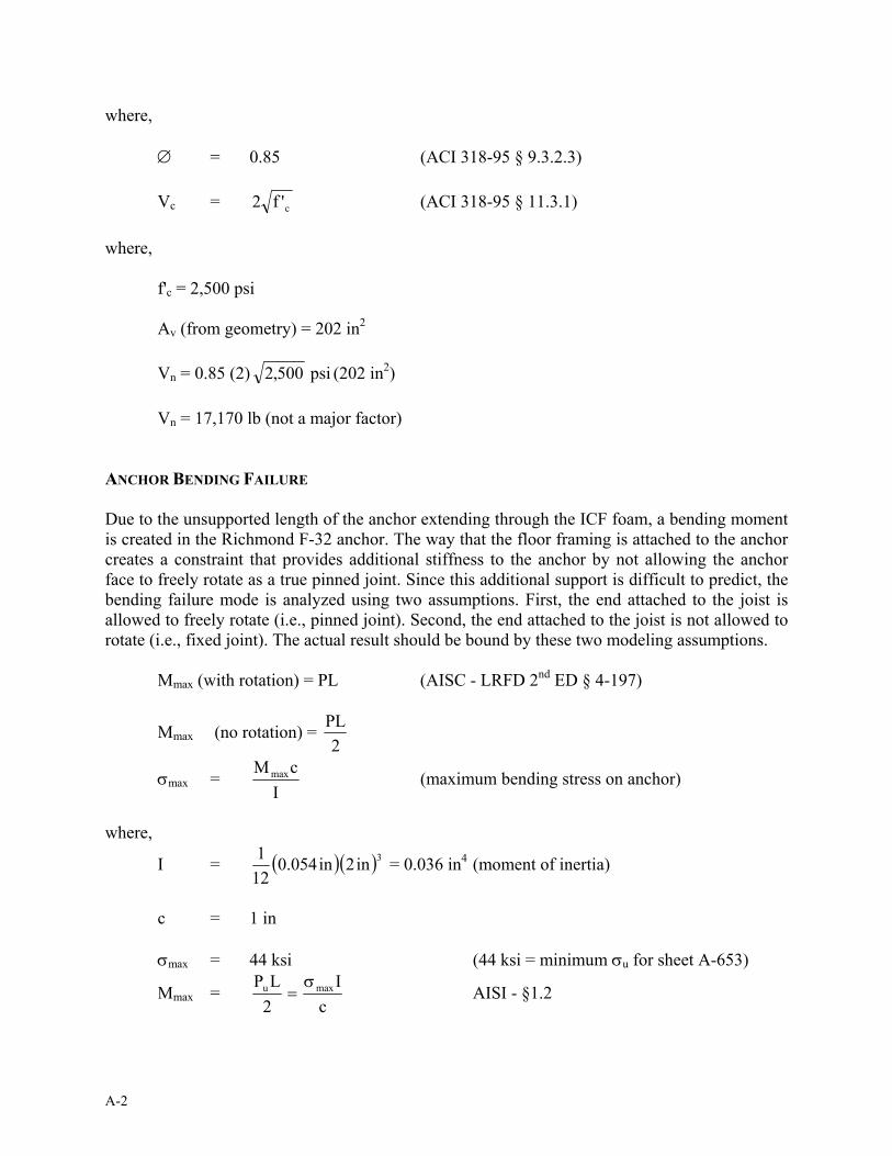
(ACI 318-95 § 9.3.2.3)∅ = 0.85
Vc = 2 c' f (ACI 318-95 § 11.3.1)
where,
f'c = 2,500 psi
Av (from geometry) = 202 in2
Vn = 0.85 (2) 500 ,2 psi (202 in2)
Vn = 17,170 lb (not a major factor)
ANCHOR BENDING FAILURE
Due to the unsupported length of the anchor extending through the ICF foam, a bending moment is created in the Richmond F-32 anchor. The way that the floor framing is attached to the anchor creates a constraint that provides additional stiffness to the anchor by not allowing the anchor face to freely rotate as a true pinned joint. Since this additional support is difficult to predict, the bending failure mode is analyzed using two assumptions. First, the end attached to the joist is allowed to freely rotate (i.e., pinned joint). Second, the end attached to the joist is not allowed to rotate (i.e., fixed joint). The actual result should be bound by these two modeling assumptions.
Mmax (with rotation) = PL (AISC - LRFD 2nd ED § 4-197)
PLMmax (no rotation) = 2
σmax = M maxc
(maximum bending stress on anchor)I
where, 1I =
12 (0.054in)(2in)3 = 0.036 in4 (moment of inertia)
c = 1 in
σmax = 44 ksi (44 ksi = minimum σu for sheet A-653) P L σ Iu maxMmax =
2 = AISI - §1.2
c
A-2

Pu = 2σmaxI
= 2(44,000psi)(0.036in 4 ) cL (1in)(2.5in)
PN = Pu/Ω Ω = 2.2
PNR = 576 lb/anchor (no rotation)
Similarly,
PR = 288 lb/anchor (with rotation)
ANCHOR SHEAR FAILURE
= 1,267 lb
AISI §1.2 AISI §E3.3
Since the load is predominantly transmitted through the Richmond F-32 anchor by shear, a logical failure mode is shear failure. The anchor is an embedded piece of cold-formed steel hardware and will therefore be analyzed following AISI §C3.2 methodology [6].
y
v F
EK
where,
E = Young's modulus = 29 e6 psiKv = shear buckling coefficient = 5.34Fy = 33,000 psi
y
v F
EK = 68.5
h/t = (2 in)/(0.054 in) = 37
where,
h = height of web = 2 int = thickness of web = 0.054 in (minimum for 16 ga steel)
h/t ≤y
v F
EK ∴use EQ C3.2-1
VN = 0.60 Fyht EQ C3.2-1, AISI § C3.2
Ωv = 1.50
A-3

V = VN/Ω = 0.60 (33,000psi)(2in)(0.054in) = 1,426 lb1.5
ANCHOR TORSION FAILURE
Since the Richmond F-32 anchor is fastened on its face which is off-center relative to the shear tab, a torsional moment will be introduced. This torque will be predominantly reacted through the screw pattern in the face of the anchor. For this reason, a minimum of four screws is required to resist the torque on the anchor. The screws have a minimum separation of 1 inch, and in no case should a single fastener be used. However, a sufficient safety factor should be used to maintain safety in the event that one or two screws are missed–a possible error in "blind" connections.
SCREW FAILURE
The load is carried from the cold formed steel floor to the Richmond F-32 anchor by fastener shear. The track evaluated in this study is 16 ga (minimum 0.054 in thickness) and the Richmond F-32 anchor is also 16 ga. From AISI Table IV-7a, each #8 screw going through 16 ga material into 16 ga material has the following ASD capacity [6].
Strength of four #8 screws per Richmond F-32 anchor
Pn = Pns/Ω
where,
Pns = 1.12 kips Ultimate shear strength per screw (#8 Screw,16ga to 16ga) Ω = 3.0 AISI Section 3.1
Pn = 4(1.12kips) The ultimate capacity per anchor is 4 x 1,120 lb = 4,480 lb3.0
Pn = 1,493 lb/anchor Allowable design strength per anchor (4 screws per anchor) without consideration of torsion (direct shear only)
If torsion is considered on the 4-screw pattern, the predicted ultimate joint capacity is near 2,000 lb and the allowable design value is 667 lb.
A-4
APPENDIX BDETERMINATION OF SAFETY AND RESISTANCE FACTORS
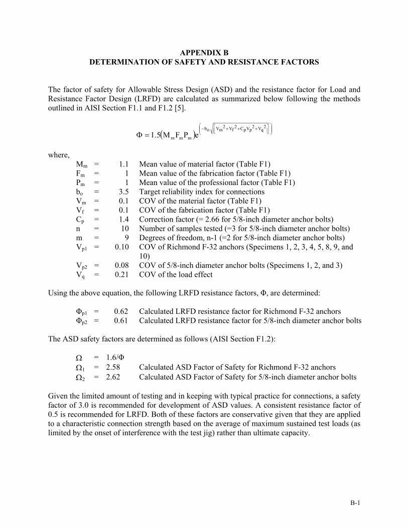
The factor of safety for Allowable Stress Design (ASD) and the resistance factor for Load and Resistance Factor Design (LRFD) are calculated as summarized below following the methods outlined in AISI Section F1.1 and F1.2 [5].
+++ 2
q V2 p VpC2
f V2 m V
−bo
Φ = 1.5(M mFmPm )e
where, Mm = 1.1 Mean value of material factor (Table F1) Fm = 1 Mean value of the fabrication factor (Table F1) Pm = 1 Mean value of the professional factor (Table F1) bo = 3.5 Target reliability index for connections Vm = 0.1 COV of the material factor (Table F1) Vf = 0.1 COV of the fabrication factor (Table F1) Cp = 1.4 Correction factor (= 2.66 for 5/8-inch diameter anchor bolts) n = 10 Number of samples tested (=3 for 5/8-inch diameter anchor bolts) m = 9 Degrees of freedom, n-1 (=2 for 5/8-inch diameter anchor bolts) Vp1 = 0.10 COV of Richmond F-32 anchors (Specimens 1, 2, 3, 4, 5, 8, 9, and
10) Vp2 = 0.08 COV of 5/8-inch diameter anchor bolts (Specimens 1, 2, and 3) Vq = 0.21 COV of the load effect
Using the above equation, the following LRFD resistance factors, Φ, are determined:
Φp1 = 0.62 Calculated LRFD resistance factor for Richmond F-32 anchors Φp2 = 0.61 Calculated LRFD resistance factor for 5/8-inch diameter anchor bolts
The ASD safety factors are determined as follows (AISI Section F1.2):
Ω = 1.6/Φ Ω1 = 2.58 Calculated ASD Factor of Safety for Richmond F-32 anchors Ω2 = 2.62 Calculated ASD Factor of Safety for 5/8-inch diameter anchor bolts
Given the limited amount of testing and in keeping with typical practice for connections, a safety factor of 3.0 is recommended for development of ASD values. A consistent resistance factor of 0.5 is recommended for LRFD. Both of these factors are conservative given that they are applied to a characteristic connection strength based on the average of maximum sustained test loads (as limited by the onset of interference with the test jig) rather than ultimate capacity.
B-1

B-2