Economic Design of EOT Crane(FINAL)
29
i A Seminar II Report On “Economic Design of EOT Cranes” Submitted In Partial Fulfillment of the Requirement For The Award of Degree of Master of Engineering In Mechanical –Design Engineering Pune University Submitted By Ashutosh kumar Under The Guidance of Prof. P.B.Deshmane Department of Mechanical Engineering Alard College of Engineering, Marunje, Pune Pune University, Pune 2012-13
description
cranes
Transcript of Economic Design of EOT Crane(FINAL)

i
A
Seminar II Report On
“Economic Design of EOT Cranes”
Submitted In Partial Fulfillment of the Requirement
For The Award of Degree of Master of Engineering
In Mechanical –Design Engineering
Pune University
Submitted By
Ashutosh kumar
Under The Guidance of
Prof. P.B.Deshmane
Department of Mechanical Engineering
Alard College of Engineering, Marunje, Pune
Pune University, Pune
2012-13

ii
Certificate
This is to certify that Mr. Ashutosh kumar has successfully completed his
seminar-II on “Economic Design of EOT Cranes” for the partial fulfillment of
the Master’s Degree in the Mechanical- Design Engineering as prescribed by the
Pune University, Pune during academic year 2012-13
Prof. P.B.Deshmane Prof. V.M.Junnarkar
(Guide) (P.G.Co-Ordinator)
Prof. V.M.Junnarkar Dr.T.R.Sontakke (H.O.D Mechanical) (Principal ACEM)

iii
ACKNOWLEDGEMENT
I wish to express my gratitude to number of people ,without whose constant guidance and
encouragement this seminar would not have been possible. I express my sincere thanks to my
seminar guide Prof. P.D.Deshmane for his continuous guidance and for providing me help as and
when required.
I am also thankful for the wholehearted support and the encouragement given by Prof.
V.M.Junnarkar, (H.O.D, Department of Mechanical Engineering).
Finally, I wish to thank my friends and all those who gave me valuable inputs directly or
indirectly in making this seminar a success.
Thanking all of you once again….
Ashutosh Kumar

iv
INDEX
SR. Name of Topic Page Number Title Sheet
Certificate
Abstract
Index
List of Figures i
List of Tables ii
1. Introduction 1
1.1 Types of Electric overhead cranes 1
1.2 Basic crane components 2
2. Literature Review 5
3. Design Details 8
3.1 Conventional details of the Crane Girder and 8
modern design of crane girder
3.2 Girder’s Plate Details 10
4. Boundary condition for Girder Design 15
5. Analysis of cases 19
6. Conclusions 23
References 24
v
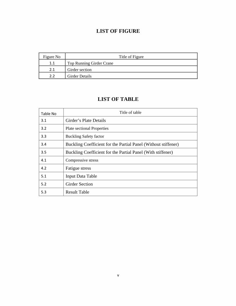
LIST OF FIGURE
Figure No Title of Figure
1.1 Top Running Girder Crane
2.1 Girder section
2.2 Girder Details
LIST OF TABLE
Table No Title of table
3.1 Girder’s Plate Details
3.2 Plate sectional Properties
3.3 Buckling Safety factor
3.4 Buckling Coefficient for the Partial Panel (Without stiffener)
3.5 Buckling Coefficient for the Partial Panel (With stiffener)
4.1 Compressive stress
4.2 Fatigue stress
5.1 Input Data Table
5.2 Girder Section
5.3 Result Table

Economic Design of EOT Cranes
AlardCollegeofEngineering,Marunje,Pune Page1
CHAPTER 1
INTRODUCTION
Cranes are industrial machines that are mainly used for materials movements in Construction
sites, production halls, assembly lines, storage areas, power stations and similar places. Their
design features vary widely according to their major operational specifications such as: type
of motion of the crane structure, weight and type of the load, location of the crane, geometric
features, operating regimes and environmental conditions
1.1 TYPES OF ELECTRIC OVERHEAD CRANES
There are various types of overhead cranes with many being highly specialized, but the great
majority of installations fall into one of three categories:
a) Top running single girder bridge cranes,
b) Top running double girder bridge cranes and
c) Under-running single girder bridge cranes.
Electric Overhead Traveling (EOT) Cranes come in various types:
1) Single girder cranes - The crane consists of a single bridge girder supported on two
end trucks. It has a trolley hoist mechanism that runs on the bottom flange of the
bridge girder.
2) Double Girder Bridge Cranes - The crane consists of two bridge girders supported on
two end trucks.
The trolley runs on rails on the top of the bridge girders.

Economic Design of EOT Cranes
AlardCollegeofEngineering,Marunje,Pune Page2
3) Gantry Cranes - These cranes are essentially the same as the regular overhead cranes
except that the bridge for carrying the trolley or trolleys is rigidly supported on two or
more legs running on fixed rails or other runway. These “legs” eliminate the
supporting runway and column system and connect to end trucks which run on a rail
either embedded in, or laid on top of, the floor.
4) Monorail - For some applications such as production assembly line or service line,
only a trolley hoist is required. The hoisting mechanism is similar to a single girder
crane with a difference that the crane doesn’t have a movable bridge and the hoisting
trolley runs on a fixed girder. Monorail beams are usually I-beams (tapered beam
flanges).
1.2 BASIC CRANE COMPONENTS
To help the reader better understand names and expressions used throughout this course, find
below is a diagram of basic crane components
Fig 1.1 Top Running Girder Crane

Economic Design of EOT Cranes
AlardCollegeofEngineering,Marunje,Pune Page3
1) Bridge - The main traveling structure of the crane which spans the width of the bay
and travels in a direction parallel to the runway. The bridge consists of two end trucks
and one or two bridge girders depending on the equipment type. The bridge also
supports the trolley and hoisting mechanism for up and down lifting of load.
2) End trucks - Located on either side of the bridge, the end trucks house the wheels on
which the entire crane travels. It is an assembly consisting of structural members,
wheels, bearings, axles, etc., which supports the bridge girder(s) or the trolley cross
member(s).
3) Bridge Girder(s) - The principal horizontal beam of the crane bridge which supports
the trolley and is supported by the end trucks.
4) Runway - The rails, beams, brackets and framework on which the crane operates.
5) Runway Rail - The rail supported by the runway beams on which the crane travels.
6) Hoist - The hoist mechanism is a unit consisting of a motor drive, coupling, brakes,
gearing, drum, ropes, and load block designed to raise, hold and lower the maximum
rated load. Hoist mechanism is mounted to the trolley.
7) Trolley - The unit carrying the hoisting mechanism which travels on the bridge rails
in a direction at right angles to the crane runway. Trolley frame is the basic structure
of the trolley on which are mounted the hoisting and traversing mechanisms.
8) Bumper (Buffer) - An energy absorbing device for reducing impact when a moving
crane or trolley reaches the end of its permitted travel, or when two moving cranes or

Economic Design of EOT Cranes
AlardCollegeofEngineering,Marunje,Pune Page4
trolleys come into contact. This device may be attached to the bridge, trolley or
runway stop.
The escalating price of structural material and energy is a global problem consequently
optimal consumption of the both cannot be considered redundant. Overhead crane, which is a
synonym for material handling in the industrial environment, utilizes structural steel for its
girder and energy (mostly electrical) for its operation. Light girder for overhead cranes not
only save material cost but also trim down energy expenditure because of subsequent
employment of low powered drive units. The general procedure for design of EOT crane
girders is accomplished through guidance stipulated in the prevailing codes and standards.
Thus optimal design in such case is not the one which just exhibit stress criteria offered in
structural design methods but the one which follows the limits restrained by the
aforementioned codes and safety rules. Shape optimization of closed box type section was
studied by Gibczynska et al.. Regarding optimal design of simple symmetrical welded box
beam Farkas J & Jarmai K incorporated bending stress, shear stress and buckling constraints
while kept cost, mass and deflection as objective function. Megson, T H.G. Hallak ,
parametrically and numerically analyzed load bearing diaphragms girder at single support
point. Narayanan, in his two consecutive papers examined strength capacity of webs with
cut-outs and rectangular holes and emphasized on prediction of stress in such cases..
Recently little literature is found which chiefly reviews crane box beam optimization except
for Tadeusz Niezgodzin´skia, Tomasz Kubiakb who considered buckling problem of web
sheets in box girders of overhead cranes due to welding of the backing strips.

Economic Design of EOT Cranes
AlardCollegeofEngineering,Marunje,Pune Page5
CHAPTER 2
LITERATURE REVIEW Fig-2.1 & 2.2 shows the basic components of Crane girder. It’s construction can be any of
the below mentioned:
(1) Beam profile Section
(2) Built-up profile Section
(3) Box Section
Fig - 2.1
Fig - 2.2

Economic Design of EOT Cranes
AlardCollegeofEngineering,Marunje,Pune Page6
Our topic is related to box girder sections. Usually for span (Girder length) more than 12
meters and load more than 10t box profile is selected because of having better sectional
property with lower weight.
In case of Box girders it is very important to define the sectional parameters in terms of
dimension. Poor selection will not lead to optimum design. There are certain instructions
about the section parameters as per IS-807-2006 listed below:
a) l/h shall not exceed 25,
b) l/b shall not exceed 60,
c) b/c shall not exceed 60.
Where,
l=Span of the crane in mm;
h=Depth of the Girder;
b=Width of the Girder;
c=Thickness of the top cover plate.
Once the Girder proportion is considered then we get some boundary to work in as to design
and optimize any girder we need to follow certain norms as well. Henceforth we will be
considering IS: 807-2006 &IS: 800-1984 as the guiding source. These standards only define
some boundary in which we have to design the structure. Basically IS: 807 & IS: 800 are the
Indian standard which is used in our country by all crane manufacturers who design as per
these Norms.
As mentioned earlier the box girder is the welded structure with the help of four plates- top
plate, bottom plate and two web plates inside the top and bottom, thus forming a box
structure. These plates are welded to each other. There are some more parts which keeps the

Economic Design of EOT Cranes
AlardCollegeofEngineering,Marunje,Pune Page7
structure balanced and stable. These are diaphragm plates, Angular stiffeners and backing
strips for web (not shown in figure). Rail on which crane trolley runs can be either welded on
the top of the web above top plate (as shown) or can be placed on the girder top at the center
of the top flange. These two positions are not only the locations where the rail can be placed
as it also depends on the design and dimensional requirement of the Crane.
Rails used in the crane girders can either be flat bar type or can be profile rails as used in
railway. This selection depends on the wheel selected for crane trolley and also sometimes as
per customer requirement.

Economic Design of EOT Cranes
AlardCollegeofEngineering,Marunje,Pune Page8
CHAPTER 3
DESIGN DETAILS
3.1 CONVENTIONAL DETAILS OF THE CRANE GIRDER AND MODERN
DESIGN OF THE CRANE GIRDER
(a) Conventional Design of the Crane Girder (Rail on Center Construction)
In such crane, Wheel load which is coming from trolley is directly applied on top
flange, which results in buckling of top flange in addition to stresses coming on it. In
order to avoid buckling we have to provide full diaphragm & short diaphragm
throughout length of girder. This not only helps in eliminating the buckling of top
flange but also helps in reducing the bending stresses coming in the rail. In addition to
these angular stiffeners are also added to web plates to avoid its buckling. Thus the
girder structure weight consists of Rail, Top & Bottom flanges, web plates, backing
strips, Short diaphragm & Long diaphragm.
(b) Modern Design of the Crane Girder (Rail on web)
In such crane, Wheel load which is coming from trolley is directly applied on web,
which results in load transmission through it. The web plates are then subjected to
buckling also but due to addition of angular stiffener the buckling effects are
nullified. Rail being on web has another one important advantage that the rail is not
subjected to bending stress. So here in this type of girder design Short diaphragms are
not required as the rails bending is taken care by web and the top flange is also not
subjected to buckling loads. Thus the girder structure weight consists of Rail, Top &
Bottom flanges, web plates, backing strips& Long diaphragm.

Economic Design of EOT Cranes
AlardCollegeofEngineering,Marunje,Pune Page9
(c) Findings of above study
Girder manufactured as per the conventional design style is heavy as compared to the Girder
manufactured as per the Modern design way.
Out of the whole crane structure weight Girder Keeps the maximum share for small span
cranes, but for long span cranes girder weights are the major decisive for cranes weight.
It is always preferable to have lower crane weight from both customer and vendor point of
view. Thus in order to reduce the crane weight the girder’s weight must be minimized.
As the weight of girder increases
The loading on End carriage increases which results in heavier end carriage.
Once the structural weight rises up the mechanical component sizing also goes up
which results in the increase in cost of the mechanical components for the same usage
and hence the crane pricing goes up.
It results in selection of heavier electrical components like motor, drive etc. Heavier
electrical requires higher electrical input which again increases the cost of the
electrical energy consumption on daily basis.
Higher crane weight needs the gantry girder much heavier so here the customer also
faces. His workshop columns and gantry needs to be heavier if the crane weight has
increased.
Ultimately daily manufacturing cost goes up.

Economic Design of EOT Cranes
AlardCollegeofEngineering,Marunje,Pune Page10
3.2 GIRDER’S PLATE DETAILS
Depending on the dimensional availability of the plates in the market some standard sizing
has been used as the regular practice now days.
FLANGE WEB Thickness (t) mm
(F)mm (W)mm 6 8 10 12 16 20
200 410 F,W F,W F,W F,W F,W F
300 490 F,W F,W F,W F,W F,W F
410 610 F,W F,W F,W F,W F,W F
490 740 F,W F,W F,W F,W F,W F
610 860 F,W F,W F,W F,W F,W F
740 980 F,W F,W F,W F,W F,W F
860 1230 F,W F,W F,W F,W F,W F
980 1480 F,W F,W F,W F,W F,W F
1230 1780 F,W F,W F,W F,W F,W F
NA
1980 W W W W W
NA 2180 W W W W W
2380 W W W W W
TABLE-3.1
Table 3.1 shows the preferred dimensions of Flanges and Web plates with various thickness
combinations. Usually rectangular Box sections with flanges more than 1230mm width and
20mm thickness are not preferred as it reduces structural stability with same construction.
Same is applicable for web plates also. But in case of web plates the total depth can be up to
2380mm with 16mm thickness. These dimensions cannot be considered as the bounding
figures.
Economic Design of EOT Cranes
AlardCollegeofEngineering,Marunje,Pune Page11
Span
(l)
m
Flange
(b)
mm
Web
(h)
mm
Flange
thk(c)
mm
web
thk
mm
Ixx(cm4) Iyy(cm4) Zxx
(cm3)
Zyy
(cm3)
wt/mtr
(kg/m)
10 200 410 6 6 17276.2 5148.8 818.8 514.9 57.5
15 200 610 6 6 45466.2 7270.2 1462 727.1 76.4
20 300 860 6 6 131102.8 24102.7 3007 1606.9 109.3
25 410 1230 8 8 499472.8 85576.1 8017.3 4174.5 206
30 490 1230 10 8 624835.8 127378.5 9997.4 5199.2 231.5
35 490 1480 10 8 976171.6 149283.1 13015.7 6093.2 262.9
40 610 1780 12 10 2115299 348965.8 23451.3 11441.5 394.4
45 740 1980 16 12 3911066 696908.6 38877.4 18835.4 559
50 740 2180 16 12 4926967 756388.3 44547.7 20443 596.6
55 860 2380 16 16 7544746 1475129 62560.1 34305.4 813.9
60 980 2480 18 16 9571243 2043057 76083.1 41695.1 900
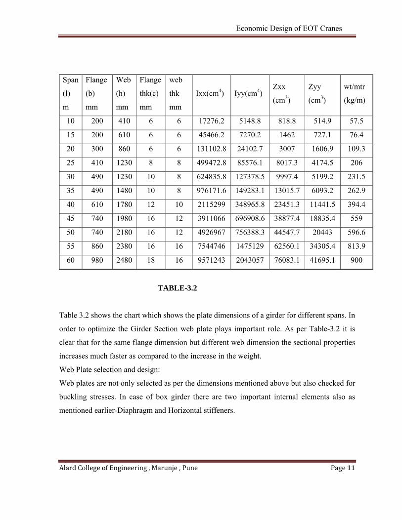
TABLE-3.2
Table 3.2 shows the chart which shows the plate dimensions of a girder for different spans. In
order to optimize the Girder Section web plate plays important role. As per Table-3.2 it is
clear that for the same flange dimension but different web dimension the sectional properties
increases much faster as compared to the increase in the weight.
Web Plate selection and design:
Web plates are not only selected as per the dimensions mentioned above but also checked for
buckling stresses. In case of box girder there are two important internal elements also as
mentioned earlier-Diaphragm and Horizontal stiffeners.
Economic Design of EOT Cranes
AlardCollegeofEngineering,Marunje,Pune Page12
Role of Diaphragm:- Diaphragm not only support the structure internally but also is a
relevant support for web plates. It divides the web plates in different part known as panels.
IS-800 clearly specifies it. This panel is detailed by two dimensions-a & b.
a – Length of the panel.
b – Depth of the panel.
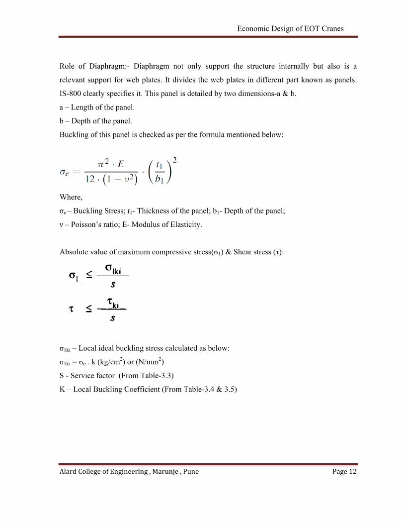
Buckling of this panel is checked as per the formula mentioned below:
Where,
σe – Buckling Stress; t1- Thickness of the panel; b1- Depth of the panel;
ν – Poisson’s ratio; E- Modulus of Elasticity.
Absolute value of maximum compressive stress(σ1) & Shear stress (τ):
σ1ki – Local ideal buckling stress calculated as below:
σ1ki = σe . k (kg/cm2) or (N/mm2)
S - Service factor (From Table-3.3)
K – Local Buckling Coefficient (From Table-3.4 & 3.5)

Economic Design of EOT Cranes
AlardCollegeofEngineering,Marunje,Pune Page13
Loading Condition Safety Factor for Buckling
of the whole plane.
Safety Factor for Buckling of the
partial plane surrounded by stiffeners.
I 1.71 + 0.180 (ϕ -1) 1.5 + 0.075 (ϕ -1)
II 1.50 + 0.125 (ϕ -1) 1.35 + 0.05 (ϕ -1)
III 1.35 + 0.075 (ϕ -1) 1.25 + 0.025 (ϕ -1)
TABLE-3.3
Buckling Coefficient for the Partial Panel (Without stiffener)
TABLE-3.4
Table-3.4 shows the panel which is nothing but the web plate section which is dimensioned
as a & b. From the above table we can select the Buckling coefficient K. This Chart is
applicable to only unstiffened web.

Economic Design of EOT Cranes
AlardCollegeofEngineering,Marunje,Pune Page14
Table 3.5 is applicable to the webs which are subjected to both vertical as well as horizontal
stiffener. In this the panel formed due to vertical diaphragm is further subdivided into small
sub panels with the help of angular stiffener. Buckling Coefficient for the Partial Panel (With
stiffener)
TABLE-3.5

Economic Design of EOT Cranes
AlardCollegeofEngineering,Marunje,Pune Page15
CHAPTER 4
BOUNDARY CONDITION FOR GIRDER DESIGN
Crane girder design is guided by various design norms like-IS: 807, FEM, CMAA, EN etc.
We have following conditions to be satisfied in order to get the girder on the safer side:
(a) Static stresses to be within limit.
(b) Fatigue Stresses to be within limit.
(c) Horizontal & vertical deflections to be within limit.
(d) Horizontal & Vertical vibrations to be within limit.
(a) Static Stress Check:
In this check we are checking the stress ratio of the structure due to static loading which
arises on account of self weight and lifted capacity. The allowable value is well defined in
design norms. Basically tensile stress ratio and compressive stress ratio is checked in this
case.
The allowable value of tensile stress and compressive stress for steel plates as per IS: 807 are
given as below:
Tensile stress value: σt
σt = 0.66*Syt*Duty factor (As per IS-807)
Where,
Syt-Yield Stress of selected material (N/mm2)
Duty Factor- 1 (For class-I), 0.95 (For Class-II), 0.9 (For class-III),0.85 (For Class-IV)
Compressive stress value: σc
Allowable compressive stress value is considered from following two conditions (As per
IS: 807)
(1)Allowable compressive stress is to be considered 1235 Kg/cm2 if the ratio b/c is equal to
or less than 38

Economic Design of EOT Cranes
AlardCollegeofEngineering,Marunje,Pune Page16
(2)When the ratio exceeds 38 then the allowable compressive stress value is considered
from the table below:
b/c σc (kg/cm2)
40 1145
44 990
48 870
52 770
56 690
60 625
TABLE-4.1
(b) Fatigue stress check
In this we check the fatigue stress occurring in the structure and compare it directly
to the corresponding fatigue stress value as guided by design Norms.
The allowable value of fatigue stress for different load cycles are given below which
is purely as per IS:807.
fatigue stress depending on stress cycles (Kg/cm2)
stress category 10000-20000 100000-500000 500000-2000000 over 2000000
A 2760 2210 1660 1660
B 2280 1720 1170 1030
C 1930 1450 960 830
D 1660 1170 690 620
E 1170 830 480 410
F 1170 960 760 620
TABLE-4.2

Economic Design of EOT Cranes
AlardCollegeofEngineering,Marunje,Pune Page17
Stress category –C is applicable to crane girders so the fatigue stresses can be cross
checked for different hoisting cycles for different stress values tabulated above.
(c ) Horizontal & Vertical deflection Check:
In this we check the girder’s deflection in both direction –Horizontal and vertical.
For vertical deflection there is general guidance as per IS:807 which speaks that the
vertical deflection must be limited by ratio of span/900. The vertical deflection should
involve the live load deflection only and no impact should be considered.
For horizontal deflection there are no such guidelines so we generally restrict it by the
same ratio as mentioned above.
(d) Horizontal and Vertical vibrations
This is one of the important check which must be done at least for long span crane.
Unfortunately there is no guideline in IS:807 for this but we follow ISO standard for
this checking.
Formulae used for checking the vertical as well as horizontal vibrations are given
below:-
Where,
fV= Vertical natural frequency
E= Modulus of Elasticity (N/mm2)
Iy= Vertical Moment of Inertia
S= Span of the crane
Mc=Crab Mass
Mg= Girder mass

Economic Design of EOT Cranes
AlardCollegeofEngineering,Marunje,Pune Page18
Above mentioned formula is given in ISO-22896. We use this formulae to check
girders vibration.
For Horizontal Vibration the calculation procedure is shown below:
Where,
Fh= Horizontal natural frequency
E= Modulus of Elasticity (N/mm2)
Iz= Horizontal Moment of Inertia
Kmg= Typical value considered as 0.4857
Mc=Crab Mass
Mg= Girder mass
The allowable values of vertical frequency and Horizontal frequency are considered
as 2 and 1.7 respectively as per ISO standard

Economic Design of EOT Cranes
AlardCollegeofEngineering,Marunje,Pune Page19
CHAPTER 5
ANALYSIS OF CASES
Case-1
When the rail is placed on the top of the girder and the rail center is matching to the web
center
Case-2
When the rail is placed on the top of the girder and the rail center is matching to the top
flange center
2.1 Basic Inputs:
PARAMETERS Case-1 Case-2
Total payload 500000 kg 500000 kg
Design Standard IS-807 IS-807
Crane Duty class II II
Bridge travelling speed 40 m/min 40 m/min
Span 37900 mm 37900 mm
Trolley Rail gauge 8500 mm 8500 mm
Trolley Wheelbase 5600 mm 5600 mm
Trolley approach at end 1 1000 mm 1000 mm
Trolley approach at end 2 1000 mm 1000 mm
Trolley Wheel diameter 900 mm 900 mm
Trolley Wheel width 170 mm 170 mm
Trolley Wheel flange height 20 mm 20 mm
Trolley Traversing speed 20 m/min 20 m/min
Trolley weight 160000 kg 160000 kg
TABLE-5.1 Input Data Table

Economic Design of EOT Cranes
AlardCollegeofEngineering,Marunje,Pune Page20
Above chart shows the basic input which is required to decide the girder section.
5.2 Girder Section
Parameters Case-1 Case-2
H 3480 3480
T1 12 18
T3 12 10
BL 1750 1750
T2 40 40
B 1750 1750
T4 40 32
F1 75 200
F2 75 125
F3 75 125
F4 75 50
RAIL A-150 A-150

Economic Design of EOT Cranes
AlardCollegeofEngineering,Marunje,Pune Page21
NOTE: Rail is intentionally not shown in the girder section. For case-1 the rail will be on the
web top and for Cae-2 the rail will be on the girder top at the centre of the top flange.
The material of the girder confirms IS-2062 with yield strength 250 N/mm2.
Based on the above data the following results are tabulated below:
Parameters Case-1 (Rail on centre) Case-2 (Rail on web)
Component Ratio Condition Ratio Condition
Stresses 0.82 <= 1 0.86 <= 1
Fatigue 0.94 <= 1 0.94 <= 1
Displacements 0.65 <= 1 0.97 <= 1
Plate buckling 0.99 <= 1 0.99 <= 1
Vibrations 0.95 <= 1 0.99 <= 1
Weight 114T 100T
Table 5.3
Observations:
If the rail is placed on the Web top then the girder will have following advantages &
Disadvantages:-
Advantages:
(i) Better utilization of box property.
(ii) Better dimensions achieved for the overall crane.
(iii) No short diaphragm required as the rail is placed on the web.
(iv) Diaphragm thickness is not governed completely by rail so lower thick
diaphragm plate can be used.
(v) The loading on End carriage decreases which results in ligter end carriage
(vi) Once the structural weight goes down the mechanical component sizing also
goes down which results in the decrease in cost of the mechanical components
for the same usage and hence the crane pricing goes down.

Economic Design of EOT Cranes
AlardCollegeofEngineering,Marunje,Pune Page22
(vii) It results in selection of lighter electrical components like motor, drive etc.
Lighter electrical requires lighter electrical input which again decreases the
cost of the electrical energy consumption on daily basis
(viii) As shown in the section 4.3 the girder weight for the same capacity decreases
by 14% for Modern girder design and hence decreasing the structural,
mechanical and electrical components in equivalent terms.
(ix) Lighter crane weight needs the gantry girder much lighter.
(x) Girder manufacturing becomes easy and fast because of absence of short
diaphragm.
(xi) Fast Manufacturing results in cheaper overall fabrication.
(xii) Better condition of hook along with rope for its position at top and bottom.
(xiii) Trolley design also becomes bit easier as the girder section constraint is
removed.
(xiv) Welding as well as bolting both becomes favorable for rail.
(xv) Ultimately daily manufacturing cost goes down for the end user.
Disadvantages:
(i) Girder experience torsion moments in addition to other moments.
(ii) Care has to be taken in mounting the rail on the web top. It should be within
specified limit.
(iii) Web plate needs to be thicker below the rail and sometimes at the end where
the shear height is low we need to add extra thick plate.

Economic Design of EOT Cranes
AlardCollegeofEngineering,Marunje,Pune Page23
CHAPTER 6
CONCLUSION
Modern Girder design gives lighter girder as compared to Conventional Girder design
methods. Of course the actual stresses and deflection values goes above but remains in the
prescribed limit, so we can utilize this to reduce the sectional dead weight.
Due to lower crane structure weight the power required to drive the complete mechanism
also decreases and hence the electrical equipment prices also go down. This result in low
electrical consumption on daily basis as well.
This results in Lighter crane by weight and hence lesser capital cost & daily running cost.

Economic Design of EOT Cranes
AlardCollegeofEngineering,Marunje,Pune Page24
REFERENCES
(1) Design Optimization of EOT Crane Bridge.(International conference of Engineering
Optimization)
(2) Optimization of an oversized beam part of a crane bridge by applying the economic
criteria.(ACTA Technical convensis-Bulletin of Engineering)
(3) Optimization of box section of the main girder of the bridge crane with rail placed
above the web plate.( Springer Verlag2012)
(4) Optimization of Double Box Girder Overhead crane in Function of Cross section
Parameter of Main Girder.( 15th International Research/Expert Conference)
(5) N Rudenko-Material Handling Equipment
(6) M P Alexandrov-Material Handling Equipment
(7) Crane supporting steel structures- R A Mac Crimon
(8) Overhead and Metallurgical cranes-Dr G M Nikolaevsky
(9) IS-807-2006, IS-800-1984,FEM-9.541, ISO-4301.