Economic and Social Council - unece.org · Modification and extension of approval of an engine type...
62
GE.18-03036(E) Economic Commission for Europe Inland Transport Committee World Forum for Harmonization of Vehicle Regulations Working Party on Pollution and Energy Seventy-sixth session Geneva, 9-12 January 2018 Report of the Working Party on Pollution and Energy (GRPE) on its seventy-sixth session Addendum 3 Adopted draft 02 series of amendments to UN Regulation No. 120 (Net power of tractors and non-road mobile machinery) The text reproduced below was adopted on the basis of GRPE-76-14 (see para. 33 of the report). United Nations ECE/TRANS/WP.29/GRPE/76/Add.3 Economic and Social Council Distr.: General 7 March 2018 English only
Transcript of Economic and Social Council - unece.org · Modification and extension of approval of an engine type...

GE.18-03036(E)
Economic Commission for Europe
Inland Transport Committee
World Forum for Harmonization of Vehicle Regulations
Working Party on Pollution and Energy
Seventy-sixth session
Geneva, 9-12 January 2018
Report of the Working Party on Pollution and Energy (GRPE) on its seventy-sixth session
Addendum 3
Adopted draft 02 series of amendments to UN Regulation No. 120 (Net power of tractors and non-road mobile machinery)
The text reproduced below was adopted on the basis of GRPE-76-14 (see para. 33 of
the report).
United Nations ECE/TRANS/WP.29/GRPE/76/Add.3
Economic and Social Council Distr.: General
7 March 2018
English only
ECE/TRANS/WP.29/GRPE/76/Add.3
2
UN Regulation No. 120
Uniform provisions concerning the approval of internal combustion engines to be installed in agricultural and forestry tractors and in non-road mobile machinery, with regard to the measurement of the net power, net torque and specific fuel consumption
Contents
Page
Regulation
1. Scope ...................................................................................................................................... 3
2. Definitions .................................................................................................................................... 3
3. Application for approval .............................................................................................................. 5
4. Approval ...................................................................................................................................... 6
5. Specifications and tests ................................................................................................................ 7
6. Conformity of production ............................................................................................................. 9
7. Penalties for non-conformity of production ................................................................................. 9
8. Modification and extension of approval of an engine type or engine family ................................ 10
9. Production definitively discontinued ............................................................................................ 10
10. Names and addresses of Technical Services responsible for conducting approval tests,
and of Type Approval Authorities ................................................................................................ 10
Annexes
1 Templates for information folder and information document ....................................................... 11
Appendix A.1: Template for information document .................................................................... 14
2 Communication ............................................................................................................................ 24
Appendix A.1: Test Report. ......................................................................................................... 28
3 Arrangements of approval marks ................................................................................................. 32
4 Method for measuring internal combustion engine net power ..................................................... 33
5 Parameters for the definition of engine types and engine families, and their operation modes .... 42
6 Checks on conformity of production ............................................................................................ 46
7 Technical characteristics of reference fuels prescribed for approval tests and to verify
conformity of production .............................................................................................................. 47
Appendix A.1: Supplementary requirements for conducting engine testing using gaseous
reference fuels comprising pipeline gas with admixture of other gases. ....................................... 57
Appendix A.2: Calculation of λ-Shift factor (Sλ)…. .................................................................... 59
Note: leave an empty page in the final document
ECE/TRANS/WP.29/GRPE/76/Add.3
3
1. Scope
1.1. This Regulation applies to the representation of the curves as a function of
engine speed of the power, torque and specific fuel consumption at full load,
indicated by the manufacturer for internal combustion engines to be used:
1.1.1. In category T vehicles1,
1.1.2. In non-road mobile machinery1, operated under variable or constant speed.
1.2. The internal combustion engines belong to one of the following categories:
1.2.1. Reciprocating internal combustion engines (positive-ignition or compression-
ignition), but excluding free piston engines;
1.2.2. Rotary piston engines (positive-ignition or compression-ignition).
2. Definitions
2.1. "Approval of an engine" means the approval of an engine type with regard to
its net power measured in accordance with the procedure specified in
Annex 4 to this Regulation;
2.2. "Approval of an engine family" means the approval of the members of an
engine family with regard to their net power in accordance with the
procedure specified in paragraphs 3 and 4 of this Regulation;
2.3. "Constant-speed engine" means an engine type-approval of which is limited to
constant-speed operation, excluding engines the constant-speed governor
function of which is removed or disabled; it may be provided with an idle
speed that can be used during start-up or shut-down and it may be equipped
with a governor that can be set to an alternative speed when the engine is
stopped;
2.4. "Constant-speed operation" means an engine operation with a governor that
automatically controls the operator demand to maintain engine speed, even under
changing load;
2.5. "DeNOX system" means an exhaust after-treatment system designed to reduce
emissions of oxides of nitrogen (NOX) (e.g. passive and active lean NOX
catalysts, NOX adsorbers and selective catalytic reduction (SCR) systems);
2.6. "Dual-fuel engine" means an engine that is designed to simultaneously operate
with a liquid fuel and a gaseous fuel, both fuels being metered separately, the
consumed amount of one of the fuels relative to the other one being able to
vary depending on the operation;
2.7. "Electronically controlled engine" means an engine using electronic control to
determine both the quantity and timing of injected fuel.
2.8. "Engine family" means a manufacturer's grouping of engines which, through
their design, fulfil the grouping criteria laid down in Annex 5 to this
Regulation;
2.9. "Engine type" means a category of engines which do not differ in such essential
engine characteristics as defined in Annex 5 to this Regulation;
1 As defined in the Consolidated Resolution on the Construction of Vehicles (R.E.3.), document
ECE/TRANS/WP.29/78/Rev.6, para. 2. -
www.unece.org/trans/main/wp29/wp29wgs/wp29gen/wp29resolutions.html

ECE/TRANS/WP.29/GRPE/76/Add.3
4
2.10. "Exhaust-gas recirculation" or "EGR" means a technical device that is part of
the emission control system and reduces emissions by routing exhaust gases
that have been expelled from the combustion chamber(s) back into the engine
to be mixed with incoming air before or during combustion, except for the use
of valve timing to increase the amount of residual exhaust gas in the
combustion chamber(s) that is mixed with incoming air before or during
combustion;
2.11. "Gaseous fuel" means any fuel which is wholly gaseous at standard ambient
conditions (298 K, absolute ambient pressure 101.3 kPa);
2.12. "Internal combustion engine" or "Engine" means an energy converter, other
than a gas turbine, designed to transform chemical energy (input) into
mechanical energy (output) with an internal combustion process; it includes,
where they have been installed, the emission control system and the
communication interface (hardware and messages) between the engine's
electronic control unit(s) and any other powertrain or category T vehicle or
non-road mobile machinery control unit necessary to comply with this
Regualtion;
2.13. "λ-shift factor" or "Sλ" means an expression that describes the required
flexibility of the engine management system regarding a change of the excess-
air ratio λ if the engine is fuelled with a gas composition different from pure
methane;
2.14. "Liquid fuel" means a fuel which exists in the liquid state at standard ambient
conditions (298 K, absolute ambient pressure 101.3 kPa);
2.15. "Liquid-fuel mode" means the normal operating mode of a dual-fuel engine
during which the engine does not use any gaseous fuel for any engine operating
condition;
2.16. "Manufacturer" means any natural or legal person who is responsible to the
Type Approval Authority for all aspects of the engine approval and for
ensuring conformity of engine production, whether or not they are directly
involved in all stages of the design and construction of the engine which is the
subject of the approval process;
2.17. "Maximum net power" means the highest value of the net power on the nominal
full-load power curve for the engine type;
2.18. "Maximum net power speed" means the engine speed at which the maximum
net power is obtained, as specified by the manufacturer;
2.19. "Maximum torque" means the highest value of the net torque measured at full
engine load.
2.20. "Maximum torque speed" means the engine speed at which the maximum
torque is obtained from the engine, as specified by the manufacturer;
2.21. "Mechanically controlled engine" means an engine using mechanical devices to
determine the quantity and timing of the delivered fuel.
2.22. "Net power" means the power obtained on a test bench at the end of the
crankshaft or its equivalent at the corresponding engine speed with the
auxiliaries and equipment listed in Table 1 of Annex 4 to this Regulation,
determined under reference atmospheric conditions;
2.23. "Parent engine" means an engine selected from an engine family in such a
way that it complies with requirements set out in Annex 5 of this Regulation;

ECE/TRANS/WP.29/GRPE/76/Add.3
5
2.24. "Particulate after-treatment system" means an exhaust after-treatment system
designed to reduce emissions of particulate pollutants through a mechanical,
aerodynamic, diffusional or inertial separation;
2.25. "Rated net power" means engine net power as declared by the manufacturer
at rated speed;
2.26. "Rated speed" means the maximum full load speed allowed by an engine's
governor, as designed by the manufacturer, or, if a governor is not present,
the speed at which the maximum net power is attained by the engine, as
specified by the manufacturer;
2.27. "Reagent" means any consumable or non-recoverable medium required and
used for the effective operation of the exhaust after-treatment system;
2.28. "Reference power" means the maximum net power for variable speed engines
and the rated net power for constant speed engines
2.29. "Reference power speed" means the engine speed at which the reference
power is obtained, as specified by the manufacturer;
2.30. "Regeneration" means an event during which emissions levels change while
the exhaust after-treatment system's performance is being restored by design
and which can be classified as continuous regeneration or infrequent (periodic)
regeneration;
2.31. "Tampering" means inactivation, adjustment or modification of the engine
control system, including any software or other logical control elements of
such a system, that has the effect, whether intended or not, of changing the
engine performance;
2.32. "Variable-speed engine" means an engine that is not a constant-speed engine;
2.33. "Wobbe index" or "W" means the ratio of the corresponding calorific value of a
gas per unit volume and the square root of its relative density under the same
reference conditions:
𝑊 = 𝐻𝑔𝑎𝑠 × √𝜌𝑎𝑖𝑟
ρ𝑔𝑎𝑠
3. Application for approval
3.1. The application for approval of an engine type or an engine family with
regard to the measurement of the net power shall be submitted by the
manufacturer or by his duly accredited representative.
3.2. The applicant shall provide the Type Approval Authority with an information
folder which includes the following:
(a) An information document, including a list of reference fuels and, where
requested by the manufacturer, any other specified fuels, fuel mixtures
or fuel emulsions referred to in paragraph 5.2.3 and described in
accordance with Annex 7 to this Regulation.
(b) All relevant data, drawings, photographs and other information relating
to the engine type or, where applicable, the parent engine;
ECE/TRANS/WP.29/GRPE/76/Add.3
6
(c) Any additional information requested by the Type Approval Authority
in the context of the type-approval application procedure.
A description of the engine type and if applicable the particulars of the engine
family referred to in Annex 5 of this Regulation.
3.3. The information folder may be provided in paper form or in an electronic
format that is accepted by the technical service and the Type Approval
Authority.
3.3.1. Applications submitted on paper shall be in triplicate. Any drawings shall be to
an appropriate scale and in sufficient detail on size A4 sheets or in a folder of
A4 format. Photographs (if any) shall show sufficient detail.
3.4. Manufacturers shall make available to the technical service responsible for
conducting the type-approval tests defined in paragraph 5, an engine
conforming to the engine type or, in the case of an engine family, to the parent
engine characteristics described in Annex 5 of this Regulation.
3.5. In the case of an application for an engine family type-approval, if the
Technical Service determines that, with regard to the selected parent engine,
the application submitted does not fully represent the engine family described
in Annex 5, manufacturers shall make available an alternative and, if necessary,
an additional parent engine which is considered by the Technical Service to
represent the engine family.
4. Approval
4.1. If the power of the engine submitted for approval pursuant to this Regulation
meets the requirements of paragraph 5. below, approval of the engine type or
family shall be granted.
4.2. An approval number shall be assigned to each engine type or family
approved. Its first two digits (at present 02 for the Regulation in its form)
shall indicate the series of amendments incorporating the most recent major
technical amendments made to the Regulation at the time of issue of the
approval. The same Contracting Party shall not assign the same number
to another engine type or family.
4.3. Notice of approval or of extension or of refusal of approval of an engine type
or an engine family pursuant to this Regulation shall be communicated to the
Parties to the 1958 Agreement applying this Regulation by means of a form
conforming to the model in Annex 2 to this Regulation.
4.4. There shall be affixed, conspicuously and in a readily accessible place as
specified on the approval form, to every engine conforming to an engine type
or an engine family approved under this Regulation a statutory marking
consisting of:
4.4.1. A circle surrounding the letter "E" followed by the distinguishing number of
the country which has granted approval2;
2 The distinguishing numbers of the Contracting Parties to the 1958 Agreement are reproduced in
Annex 3 to the Consolidated Resolution on the Construction of Vehicles (R.E.3), document
ECE/TRANS/WP.29/78/Rev.6/ -
www.unece.org/trans/main/wp29/wp29wgs/wp29gen/wp29resolutions.html

ECE/TRANS/WP.29/GRPE/76/Add.3
7
4.4.2. The number of this Regulation, followed by the letter "R", a dash and the
approval number to the right of the circle prescribed in paragraph 4.4.1.
Where the statutory marking of the engine is not visible without removing
parts, the vehicle manufacturer shall affix to the category T vehicle or the
non-road mobile machinery, in a visible manner, a duplicate of the marking
provided by the manufacturer..
4.5. If the engine conforms to an approved type or family under one or more other
Regulations annexed to the Agreement, in the country which has granted
approval under this Regulation, the symbol prescribed in paragraph 4.4.1.
need not be repeated; in such a case the Regulation and approval numbers
and the additional symbols of all the Regulations under which approval has
been granted under this Regulation shall be placed in vertical columns to the
right of the symbol prescribed in paragraph 4.4.1.
4.6. The statutory marking shall be placed close to or on the data plate affixed by
the manufacturer to the approved type.
4.7. Annex 3 to this Regulation gives examples of arrangements of approval
marks.
4.8. Every engine conforming to an engine type or an engine family approved
under this Regulation must bear, in addition to the approval mark:
(a) The trademark or trade name of the manufacturer of the engine and the
address at which it can be contacted;
(b) The manufacturer's engine type or engine family designation in case the
engine type belongs to a family;
(c) The unique engine identification number;
5. Specifications and tests
5.1. General
The components liable to affect the power of the engine shall be so designed,
constructed and assembled as to enable the engine in normal use, despite the
vibrations to which it may be subjected, to comply with the provisions of this
Regulation.
5.1.1. For this purpose, the engine net power measured in accordance with the test
conditions and detailed technical procedures set out in Annex 4 to this
Regulation, using the fuel(s) specified in paragraph 5.2.3. and corrected
according to the power correction factors defined in paragraph 5 of Annex 4 of
this Regulation shall not deviate by more than the tolerances specified in
paragraph 5.3. from the power curves declared by the manufacturer.
5.2. Description of tests for internal combustion engines
5.2.1. The net power test shall consist of either
(a) A run at full throttle for mechanically controlled positive ignition
engines a run fixed full load fuel injection pump setting for
mechanically controlled compression ignition engines; or
(b) A run at the required fuel system settings to produce the manufacturer
specified power for electronically controlled engines.

ECE/TRANS/WP.29/GRPE/76/Add.3
8
The engine shall be equipped as specified in Table 1 of Annex 4 to this
Regulation.
5.2.2. Measurements shall be taken at a sufficient number of engine speeds to
define correctly the power, torque and specific fuel consumption curves
between the lowest and the highest engine speeds recommended by the
manufacturer. This range of speeds must include the rotational speeds at
which the engine produces its rated net power, its maximum power
and its maximum torque.
5.2.3. The testing of an engine type or engine family shall be carried out by using the
following reference fuels or fuel combinations described in Annex 7, as
appropriate:
(a) Diesel;
(b) Petrol;
(c) Petrol/oil mixture, for two stroke SI engines;
(d) Natural gas/bio methane;
(e) Liquid petroleum gas (LPG);
(f) Ethanol.
The engine type or engine family shall, in addition, meet the requirements set
out in paragraph 5.1.1. in respect of any other specified fuels, fuel mixtures or
fuel emulsions included by a manufacturer in an application for type- approval
and described in Annex 1 to this Regulation.
5.2.3.1. The fuel used shall be specified in the test report.
5.2.4. Measurements shall be carried out according to the provisions of Annex 4 to
this Regulation.
5.2.5. The test report shall contain the results and all the calculations required to
determine the net power, as listed in the appendix A.1 to Annex 2 to this
Regulation together with the characteristics of the engine, as listed in
Annex 1 to this Regulation.
5.3. Interpretation of Results
5.3.1. Net power
The net power declared by the manufacturer for the type of engine (or parent
engine) shall be accepted if it does not differ by more than the values
indicated in the table below, from the corrected values measured by the
technical service on the engine submitted for testing.
Engine Type Reference power [%]
Other measurement points
on the curve [%]
Tolerance for engine
speed [%]
General ±2 ±4 ±1.5
Petrol fuelled spark ignited
engines with governor ±4 ±6 ±4
Petrol fuelled spark ignited
engines without governor ±4 ±10 ±4
ECE/TRANS/WP.29/GRPE/76/Add.3
9
5.3.2. Reference power speed
The reference power speed declared by the manufacturer shall not deviate by
more than 100 min-1 from the value measured by the technical service on the
engine submitted for testing. For spark ignited petrol fuelled engines, the
reference power speed declared by the manufacturer shall not deviate from
the value measured by the technical service on the engine submitted for
testing by more than 150 min-1 for engines provided with governor and for
engines without governor 350 min-1 or 4 per cent, whichever is smaller.
5.3.3. Fuel consumption
The specific fuel consumption curve declared by the manufacturer for the
type of engine (or parent engine) shall be accepted if it does not differ by
more than ±8 per cent at all measurement points from the values measured
for the same points by the technical service on the engine submitted for
testing.
5.3.4. Engine family
In case of compliance of the parent engine to the conditions
in paragraphs 5.3.1. and 5.3.2., the acceptance is automatically extended to
all the declared curves of the family members.
5.4. Engine types and engine families shall be designed and fitted with engine
control strategies in such a way as to prevent tampering to the extent possible.
6. Conformity of production
The conformity of production procedures shall comply with those set out in
the Agreement, Schedule 1 (E/ECE/324 - E/ECE/TRANS/505/Rev.3), with
the following requirements:
6.1. Engines approved under this Regulation shall be so manufactured as to
conform to the type approved.
6.2. The minimum requirements for conformity of production control procedures
set forth in Annex 6 to this Regulation shall be complied with.
7. Penalties for non-conformity of production
7.1. The approval granted in respect of an engine type or an engine family
pursuant to this Regulation may be withdrawn if the requirements set forth in
paragraph 6.1. above are not met or if an engine or an engine family bearing
the approval mark does not conform to the type approved.
7.2. If a Contracting Party to the 1958 Agreement applying this Regulation
withdraws an approval it has previously granted, it shall forthwith so notify
the other Contracting Parties applying this Regulation, by means of a
communication form conforming to the model in Annex 2 to this Regulation.
ECE/TRANS/WP.29/GRPE/76/Add.3
10
8. Modification and extension of approval of an engine type or engine family
8.1. Every modification of an engine type or an engine family with regard to the
characteristics in Annex 1, shall be notified to the Type Approval Authority
which approved the engine type or engine family. The Type Approval
Authority may then either:
8.1.1. Consider that the modifications made are unlikely to have any appreciable
adverse effect and that in any case the engine still complies with the
requirements; or
8.1.2. Require a further test report from the Technical Service responsible for
conducting the tests.
8.2. Confirmation or refusal of approval, specifying the alterations shall be
communicated by the procedure specified in paragraph 4.3. above to the
Parties to the Agreement applying this Regulation.
8.3. The Type Approval Authority issuing the extension of approval shall assign a
series number for such an extension and inform thereof the other Parties to
the 1958 Agreement applying this Regulation by means of a communication
form conforming to the model in Annex 2 to this Regulation.
9. Production definitively discontinued
If the holder of an approval completely ceases to manufacture an engine type
or an engine family approved in accordance with this Regulation, he shall so
inform the authority which granted the approval. Upon receiving the relevant
communication that authority shall inform thereof the other Parties to the
1958 Agreement applying this Regulation by means of a communication
form conforming to the model in Annex 2 to this Regulation.
10. Names and addresses of Technical Services responsible for conducting approval tests, and of Type Approval Authorities
The Parties to the Agreement which apply this Regulation shall communicate
to the United Nations Secretariat the names and addresses of the Technical
Services responsible for conducting approval tests, and/or the Type Approval
Authorities which grant approval, and to which forms certifying approval or
extension or refusal of approval, issued in other countries, are to be sent.

ECE/TRANS/WP.29/GRPE/76/Add.3
Annex 1
11
Annex 1
Templates for information folder and information document
1. Information folder
The information folder referred to in paragraph 3 of this Regulation shall
contain the following:
1.1. A list of contents;
1.2. Manufacturer's declaration and supporting data demonstrating that the engine
control strategies fitted are designed in such a way as to prevent tampering to
the extent possible, as referred to in paragraph 5.4.
1.2.1. For electronically controlled engine types and engine families that use an
Electronic Control Unit (ECU) as part of the engine control system the
information shall include a description of the provisions taken to prevent
tampering with and modification of the ECU including the facility for
updating using a manufacturer approved programme or calibration;
1.2.2. For mechanically controlled engine types and engine families the information
shall include a description of the provisions taken to prevent tampering with
and modification of the adjustable parameters of the engine control system.
This shall include the tamper resistant components such as carburettor limiter
caps or sealing of carburettor screws or special screws not adjustable by user;
1.3. A description of the overall quality-assurance management systems for
conformity of production in accordance to paragraph 6. of this Regulation;
1.4. The completed information document as set out in paragraph 2 of this Annex;
1.4.1 Where the particulars appearing in the information document for an engine
approval have changed, the manufacturer shall submit revised pages to the
approval authority showing clearly the nature of the change(s) and the date of
re-issue;
1.5. All relevant data, drawings, photographs and other information as required in
the information document;
2. Information document
The information document shall have a reference number issued by the
applicant.
2.1. All information documents shall contain the following:
2.1.1. the general information set out in Part A of Appendix A.1 to this Annex;
2.1.2. the information set out in Part B of Appendix A.1 to this Annex, to identify the
common design parameters of all engine types within an engine family or
applicable to the engine type where not part of an engine family, intended for
type approval;
2.1.3. the information set out in Part C of Appendix A.1 to this Annex.
2.2. Explanatory notes on creation of information document:
2.2.1. Upon agreement of the approval authority, the information in paragraph 2.1.2
and 2.1.3 may be presented in an alternative format;

ECE/TRANS/WP.29/GRPE/76/Add.3
Annex 1
12
2.2.2. Reserved
2.2.3. Only those paragraphs of this Annex relevant for the particular engine family,
engine types within the engine family or engine type shall be listed; in any
case, the list shall adhere to the proposed numbering system,
2.2.4. Where several options separated by forward slash are given for an entry, the
unused options shall be struck out, or only the used option(s) shall be shown;
2.2.5. When the same value for or description of a certain engine characteristic
applies for several or all members of an engine family the corresponding cells
may be merged.
2.2.6. Where a picture, diagram or detailed information is required, a reference to an
appendix may be given;
2.2.7. Where a ‘type’ of a component is requested, the information supplied shall
uniquely identify the component; this may be a list of characteristic, a
manufacturers' name and part or drawing number, a drawing, or a combination
of the aforementioned or other methods that achieves the same result.
2.3. Engine type designation and engine family designation
The manufacturer shall allocate to each engine type and engine family a unique
alphanumeric code.
2.3.1. In the case of an engine type, the code is named engine type designation and
shall clearly and unequivocally identify those engines presenting a unique
combination of technical features for those items set out in Part C of Appendix
A.1 to this Annex applicable to the engine type.
2.3.2. In the case of engine types within an engine family, the whole code is named
Family-Type or ‘FT’, and is composed of two sections: the first section is
named engine family designation and identifies the engine family; the second
section is the engine type designation of each particular engine type within the
engine family;
The engine family designation shall clearly and unequivocally identify those
engines presenting a unique combination of technical features for those items
set out in Parts B and C of Appendix A.1 to this Annex applicable to the
particular engine family.
The FT shall clearly and unequivocally identify those engines presenting a
unique combination of technical features for those items set out in Part C of
Appendix A.1 to this Annex applicable to the engine type within the engine
family.
2.3.2.1. The manufacturer may use the same engine family designation to identify the
same engine family under two or more engine categories.
2.3.2.2. The manufacturer shall not use the same engine family designation to identify
more than one engine family under the same engine category.
2.3.2.3. Display of the FT
In the FT, a space shall be left between the engine family designation and the
engine type designation, as shown in the example below:
‘159AF[space]0054’

ECE/TRANS/WP.29/GRPE/76/Add.3
Annex 1
13
2.3.3. Number of characters
The number of characters shall not exceed the following:
(a) 15 for the engine family designation;
(b) 25 for the engine type designation;
(c) 40 for the FT.
2.3.4. Characters allowed
The engine type designation and engine family designation shall be made up of
Roman letters and/or Arabic numerals;
2.3.4.1. The use of brackets and hyphens is permitted provided they do not replace a
letter or a numeral.
2.3.4.2. The use of variable characters is permitted; variable characters shall be denoted
by a ‘#’, where the variable character is unknown at the time of notification;
2.3.4.2.1. The reasons for using such variable characters shall be explained to the
technical service and Type Approval Authority.
ECE/TRANS/WP.29/GRPE/76/Add.3
Annex 1 – Appendix A.1
14
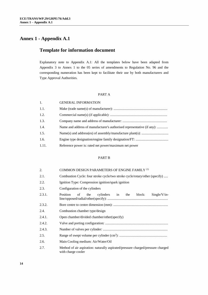
Annex 1 - Appendix A.1
Template for information document
Explanatory note to Appendix A.1: All the templates below have been adapted from
Appendix 3 to Annex 1 to the 05 series of amendments to Regulation No. 96 and the
corresponding numeration has been kept to facilitate their use by both manufacturers and
Type Approval Authorities.
PART A
1. GENERAL INFORMATION
1.1. Make (trade name(s) of manufacturer): ................................................................
1.2. Commercial name(s) (if applicable): ....................................................................
1.3. Company name and address of manufacturer: .....................................................
1.4. Name and address of manufacturer's authorised representative (if any): .............
1.5. Name(s) and address(es) of assembly/manufacture plant(s): ................................
1.6. Engine type designation/engine family designation/FT: .......................................
1.11. Reference power is: rated net power/maximum net power
PART B
2. COMMON DESIGN PARAMETERS OF ENGINE FAMILY (1)
2.1. Combustion Cycle: four stroke cycle/two stroke cycle/rotary/other (specify) .....
2.2. Ignition Type: Compression ignition/spark ignition
2.3. Configuration of the cylinders
2.3.1. Position of the cylinders in the block: Single/V/in-
line/opposed/radial/other(specify): ........................................................................
2.3.2. Bore centre to centre dimension (mm): .................................................................
2.4. Combustion chamber type/design
2.4.1. Open chamber/divided chamber/other(specify)
2.4.2. Valve and porting configuration: ...........................................................................
2.4.3. Number of valves per cylinder: .............................................................................
2.5. Range of swept volume per cylinder (cm3): .........................................................
2.6. Main Cooling medium: Air/Water/Oil
2.7. Method of air aspiration: naturally aspirated/pressure charged/pressure charged
with charge cooler

ECE/TRANS/WP.29/GRPE/76/Add.3
Annex 1 – Appendix A.1
15
2.8. Fuel
2.8.1. Fuel Type: Diesel (non-road gas-oil)/Ethanol for dedicated compression
ignition engines (ED95)/Petrol (E10)/ Ethanol (E85)/(Natural
gas/Biomethane)/Liquid Petroleum Gas (LPG)
2.8.1.1. Sub Fuel type (Natural gas/Biomethane only): Universal fuel — high calorific
fuel (H-gas) and low calorific fuel (L-gas)/Restricted fuel — high calorific fuel
(H-gas)/Restricted fuel — low calorific fuel (L-gas)/Fuel specific (LNG);
2.8.2. Fuelling arrangement: Liquid-fuel only/Gaseous-fuel only/Dual-fuel type
1A/Dual-fuel type 1B/Dual-fuel type 2A/Dual-fuel type 2B/Dual-fuel type 3B
2.8.3. List of additional fuels, fuel mixtures or emulsions compatible with use by the
engine declared by the manufacturer in accordance with paragraph 5.2.3. of this
Regulation (provide reference to recognised standard or specification):
.........................................................................................................
2.8.4. Lubricant added to fuel: Yes/No
2.8.4.1. Specification:
................................................................................................................................
2.8.4.2. Ratio of fuel to oil: ................................................................................................
2.8.5. Fuel supply type: Pump (high pressure) line and injector/in-line pump or
distributor pump/Unit injector/ Common rail/Carburettor)/port injector/direct
injector/Mixing unit/other(specify): .......................................................................
2.9. Engine management systems: mechanical/electronic control strategy (2)
2.10. Miscellaneous devices: Yes/No (if yes provide a schematic diagram of the
location and order of the devices)
2.10.1. Exhaust gas recirculation (EGR): Yes/No (if yes, complete section 3.10.1 and
provide a schematic diagram of the location and order of the devices)
2.10.2. Water injection: Yes/No (if yes, complete section 3.10.2 and provide a
schematic diagram of the location and order of the devices)
2.10.3. Air injection: Yes/No (if yes, complete section 3.10.3 and provide a schematic
diagram of the location and order of the devices)
2.10.4. Others: Yes/No (if yes specify, complete section 3.10.4 and provide a
schematic diagram of the location and order of the devices):
.................................................................................................................................
2.11. Exhaust after-treatment system: Yes/No (if yes provide a schematic diagram of
the location and order of the devices)
2.11.1. Oxidation catalyst: Yes/No
(if yes, complete section 3.11.2)
2.11.2. De NOX system with selective reduction of NOX (addition of reducing agent):
Yes/No
(if yes, complete section 3.11.3)
2.11.3. Other De NOX systems: Yes/No
(if yes, complete section 3.11.3)
2.11.4. Three-way catalyst combining oxidation and NOX reduction: Yes/No
(if yes, complete section 3.11.3)
ECE/TRANS/WP.29/GRPE/76/Add.3
Annex 1 – Appendix A.1
16
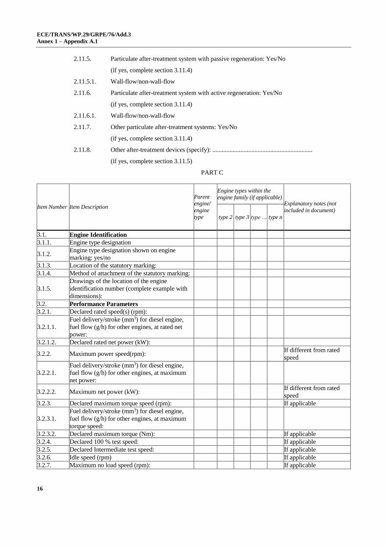
2.11.5. Particulate after-treatment system with passive regeneration: Yes/No
(if yes, complete section 3.11.4)
2.11.5.1. Wall-flow/non-wall-flow
2.11.6. Particulate after-treatment system with active regeneration: Yes/No
(if yes, complete section 3.11.4)
2.11.6.1. Wall-flow/non-wall-flow
2.11.7. Other particulate after-treatment systems: Yes/No
(if yes, complete section 3.11.4)
2.11.8. Other after-treatment devices (specify): ................................................................
(if yes, complete section 3.11.5)
PART C
Item Number Item Description
Parent
engine/
engine
type
Engine types within the
engine family (if applicable) Explanatory notes (not
included in document)
type 2 type 3 type … type n
3.1. Engine Identification
3.1.1. Engine type designation
3.1.2. Engine type designation shown on engine
marking: yes/no
3.1.3. Location of the statutory marking:
3.1.4. Method of attachment of the statutory marking:
3.1.5.
Drawings of the location of the engine
identification number (complete example with
dimensions):
3.2. Performance Parameters
3.2.1. Declared rated speed(s) (rpm):
3.2.1.1.
Fuel delivery/stroke (mm3) for diesel engine,
fuel flow (g/h) for other engines, at rated net
power:
3.2.1.2. Declared rated net power (kW):
3.2.2. Maximum power speed(rpm): If different from rated
speed
3.2.2.1.
Fuel delivery/stroke (mm3) for diesel engine,
fuel flow (g/h) for other engines, at maximum
net power:
3.2.2.2. Maximum net power (kW): If different from rated
speed
3.2.3. Declared maximum torque speed (rpm): If applicable
3.2.3.1.
Fuel delivery/stroke (mm3) for diesel engine,
fuel flow (g/h) for other engines, at maximum
torque speed:
3.2.3.2. Declared maximum torque (Nm): If applicable
3.2.4. Declared 100 % test speed: If applicable
3.2.5. Declared Intermediate test speed: If applicable
3.2.6. Idle speed (rpm) If applicable
3.2.7. Maximum no load speed (rpm): If applicable

ECE/TRANS/WP.29/GRPE/76/Add.3
Annex 1 – Appendix A.1
17
Item Number Item Description
Parent
engine/
engine
type
Engine types within the
engine family (if applicable) Explanatory notes (not
included in document)
type 2 type 3 type … type n
3.2.8 Declared minimum torque (Nm) If applicable
3.3. Run-in procedure Optional at choice of
manufacturer
3.3.1. Run-in time:
3.3.2. Run-in cycle:
3.4. Engine test
3.4.1. Specific fixture required: Yes/No If applicable
3.4.1.1
Description, including photographs and/or
drawings, of the system for mounting the engine
on the test bench including the power
transmission shaft for connection to the
dynamometer:
3.4.2. Exhaust mixing chamber permitted by
manufacturer: Yes/No If applicable
3.4.2.1. Exhaust mixing chamber description,
photograph and/or drawing: If applicable
3.5. Lubrication system
3.5.1. Lubricant temperature If applicable
3.5.1.1. Minimum (⁰C):
3.5.1.2. Maximum (⁰C):
3.6. Combustion Cylinder
3.6.1. Bore(mm):
3.6.2. Stroke(mm):
3.6.3. Number of cylinders:
3.6.4. Engine total swept volume (cm3):
3.6.5. Swept volume per cylinder as % of parent
engine: If engine family
3.6.6. Volumetric compression ratio: Specify tolerance
3.6.7. Combustion system description:
3.6.8. Drawings of combustion chamber and piston
crown:
3.6.9. Minimum cross sectional area of inlet and outlet
ports (mm2):
3.6.10. Valve timing
3.6.10.1. Maximum lift and angles of opening and closing
in relation to dead centre or equivalent data:
3.6.10.2. Reference and/or setting range:
3.6.10.3. Variable valve timing system: Yes/No If applicable and where
intake and/or exhaust
3.6.10.3.1. Type: continuous/(on/off)
3.6.10.3.2. Cam phase shift angle:
3.6.11. Porting configuration 2-stroke only, if
applicable
3.6.11.1. Positon, size and number:
3.7. Cooling system Complete relevant section
3.7.1. Liquid cooling
3.7.1.1. Nature of liquid:
3.7.1.2. Circulating pumps: Yes/No

ECE/TRANS/WP.29/GRPE/76/Add.3
Annex 1 – Appendix A.1
18
Item Number Item Description
Parent
engine/
engine
type
Engine types within the
engine family (if applicable) Explanatory notes (not
included in document)
type 2 type 3 type … type n
3.7.1.2.1. type(s):
3.7.1.2.2. Drive ratio(s): If applicable
3.7.1.3. Minimum coolant temperature at outlet (⁰C):
3.7.1.4. Maximum coolant temperature at outlet (⁰C):
3.7.2. Air cooling
3.7.2.1. fan: Yes/No
3.7.2.1.1. type(s):
3.7.2.1.2. Drive ratio(s): If applicable
3.7.2.2. Maximum temperature at reference point (⁰C):
3.7.2.2.1. Reference point location
3.8. Aspiration
3.8.1. Maximum allowable intake depression at 100%
engine speed and at 100% load (kPa)
3.8.1.1. With clean air cleaner:
3.8.1.2. With dirty air cleaner:
3.8.1.3. Location, of measurement:
3.8.2. Pressure charger(s): Yes/No
3.8.2.1. Type(s):
3.8.2.2.
Description and schematic diagram of the
system (e.g. maximum charge pressure, waste
gate, VGT, Twin turbo, etc.):
3.8.3. Charge air cooler: Yes/No
3.8.3.1. Type: air-air/air-water/other(specify)
3.8.3.2. Maximum charge air cooler outlet temperature
at 100% speed and 100% load (⁰C):
3.8.3.3.
Maximum allowable pressure drop across
charge cooler at 100% engine speed and at
100% load (kPa):
3.8.4. Intake throttle valve: Yes/No
3.8.5. Device for recycling crankcase gases: Yes/No
3.8.5.1. If yes, description and drawings:
3.8.5.2. If no, compliance with paragraph 5.7. of this
Regulation: Yes/No
3.8.6. Inlet path If applicable
3.8.6.1. Description of inlet path, (with drawings,
photographs and/or part numbers):
3.8.7. Air filter If applicable
3.8.7.1. Type:
3.8.8. Intake air-silencer If applicable
3.8.8.1. Type:
3.9. Exhaust system
3.9.1.
Description of the exhaust system (with
drawings, photos and/or part numbers as
required):
If applicable
3.9.2. Maximum exhaust temperature (⁰C):
3.9.3. Maximum permissible exhaust backpressure at
100% engine speed and at 100% load (kPa):

ECE/TRANS/WP.29/GRPE/76/Add.3
Annex 1 – Appendix A.1
19
Item Number Item Description
Parent
engine/
engine
type
Engine types within the
engine family (if applicable) Explanatory notes (not
included in document)
type 2 type 3 type … type n
3.9.3.1. Location of measurement:
3.9.4.
Exhaust backpressure at loading level specified
by manufacturer for variable restriction after-
treatment at start of test (kPa):
3.9.4.1. Location and speed/load conditions:
3.9.5. Exhaust throttle valve: Yes/No
3.10. Miscellaneous devices: Yes/No
3.10.1. Exhaust gas recirculation (EGR)
3.10.1.1. Characteristics: cooled/uncooled, high
pressure/low pressure/other (specify):
3.10.2. Water injection
3.10.2.1. Operation principle:
3.10.3. Air injection
3.10.3.1. Operation principle
3.10.4. Others
3.10.4.1. Type(s)
3.11. Exhaust after-treatment system
3.11.1. Location
3.11.1.1. Place(s) and maximum/minimum distance(s)
from engine to first after-treatment device:
3.11.1.2.
Maximum temperature drop from exhaust or
turbine outlet to first after-treatment device (⁰C)
if stated:
3.11.1.2.1. Test conditions for measurement:
3.11.1.3. Minimum temperature at inlet to first after-
treatment device, (⁰C) if stated:
3.11.1.3.1. Test conditions for measurement:
3.11.2. Oxidation catalyst
3.11.2.1. Number of catalytic converters and elements:
3.11.2.2. Dimensions and volume of the catalytic
converter(s): Or drawing
3.11.2.3. Total charge of precious metals (g):
3.11.2.4. Relative concentration of each compound (%):
3.11.2.5. Substrate (structure and material):
3.11.2.6. Cell density:
3.11.2.7. Type of casing for the catalytic converter(s):
3.11.3. Catalytic exhaust after-treatment system for
NOX or three way catalyst
3.11.3.1. Type:
3.11.3.2. Number of catalytic converters and elements:
3.11.3.3. Type of catalytic action:
3.11.3.4. Dimensions and volume of the catalytic
converter(s): Or drawing
3.11.3.5. Total charge of precious metals (g):
3.11.3.6. Relative concentration of each compound (%):
3.11.3.7. Substrate (structure and material):
3.11.3.8. Cell density:

ECE/TRANS/WP.29/GRPE/76/Add.3
Annex 1 – Appendix A.1
20
Item Number Item Description
Parent
engine/
engine
type
Engine types within the
engine family (if applicable) Explanatory notes (not
included in document)
type 2 type 3 type … type n
3.11.3.9. Type of casing for the catalytic converter(s):
3.11.3.10. Method of regeneration: If applicable
3.11.3.10.1. Infrequent regeneration: Yes/No: If yes, complete section
3.11.6.
3.11.3.11. Normal operating temperature range (⁰C):
3.11.3.12. Consumable reagent: Yes/No
3.11.3.12.1. Type and concentration of reagent needed for
catalytic action:
3.11.3.12.2.
Lowest concentration of the active ingredient
present in the reagent that does not activate
warning system (CDmin) (%vol):
3.11.3.12.3. Normal operational temperature range of
reagent:
3.11.3.12.4. International standard: If applicable
3.11.3.13. NOX sensor(s): Yes/No
3.11.3.13.1. Type:
3.11.3.13.2. Location(s)
3.11.3.14. Oxygen sensor(s): Yes/No
3.11.3.14.1. Type:
3.11.3.14.2. Location(s):
3.11.4. Particulate after-treatment system
3.11.4.1. Type of filtration: wall-flow/ non-wall-
flow/other (specify)
3.11.4.2. Type:
3.11.4.3. Dimensions and capacity of the particulate after-
treatment system: Or drawing
3.11.4.4. Location place(s) and maximum and minimum
distance(s) from engine:
3.11.4.5. Method or system of regeneration, description
and/or drawing:
3.11.4.5.1. Infrequent regeneration: Yes/No If yes, complete section
3.11.6.
3.11.4.5.2. Minimum exhaust gas temperature for initiating
regeneration procedure (⁰C):
3.11.4.6. Catalytic coating: Yes/No
3.11.4.6.1. Type of catalytic action:
3.11.4.7. Fuel borne catalyst (FBC): Yes/No
3.11.4.8. Normal operating temperature range (⁰C):
3.11.4.9. Normal operating pressure range (kPa)
3.11.4.10. Storage capacity soot/ash (g):
3.11.4.11. Oxygen sensor(s): Yes/No
3.11.4.11.1. Type:
3.11.4.11.2. Location(s):
3.11.5. Other after-treatment devices
3.11.5.1. Description and operation:
3.11.6. Infrequent Regeneration
3.11.6.1. Number of cycles with regeneration

ECE/TRANS/WP.29/GRPE/76/Add.3
Annex 1 – Appendix A.1
21
Item Number Item Description
Parent
engine/
engine
type
Engine types within the
engine family (if applicable) Explanatory notes (not
included in document)
type 2 type 3 type … type n
3.11.6.2. Number of cycles without regeneration
3.11.7. Other devices or features
3.11.7.1. Type(s)
3.12. Fuel feed for liquid-fuelled CI or, where
applicable, dual-fuel engines
3.12.1. Feed pump
3.12.1.1. Pressure (kPa) or characteristic diagram:
3.12.2. Injection system
3.12.2.1. Pump
3.12.2.1.1. Type(s):
3.12.2.1.2. Rated pump speed (rpm):
3.12.2.1.3. mm3 per stroke or cycle at full injection at rated
pump speed: Specify tolerance
3.12.2.1.4. Torque peak pump speed (rpm):
3.12.2.1.5. mm3 per stroke or cycle at full injection at
torque peak pump speed Specify tolerance
3.12.2.1.6. Characteristic diagram: As alternative to entries
3.12.2.1.1. to 3.12.2.1.5.
3.12.2.1.7. Method used: on engine/on pump bench
3.12.2.2. Injection timing
3.12.2.2.1. Injection timing curve: Specify tolerance, if
applicable
3.12.2.2.2. Static Timing: Specify tolerance
3.12.2.3. Injection piping
3.12.2.3.1. Length(s) (mm):
3.12.2.3.2. Internal diameter (mm):
3.12.2.4. Common rail: Yes/No
3.12.2.4.1. Type:
3.12.3. Injector(s)
3.12.3.1. Type(s):
3.12.3.2. Opening pressure (kPa): Specify tolerance
3.12.4. ECU: Yes/No
3.12.4.1. Type(s):
3.12.4.2. Software calibration number(s):
3.12.4.3.
Communication standard(s) for access to data
stream information: ISO 27145 with ISO 15765-
4 (CAN-based)/ISO 27145 with ISO 13400
(TCP/IP-based)/SAE J1939-73
3.12.5. Governor
3.12.5.1. Type(s):
3.12.5.2. Speed at which cut-off starts under full load: Specify range, if
applicable
3.12.5.3. Maximum no-load speed: Specify range, if
applicable
3.12.5.4. Idle speed: Specify range, if
applicable
3.12.6. Cold-start system: Yes/No
3.12.6.1. Type(s):

ECE/TRANS/WP.29/GRPE/76/Add.3
Annex 1 – Appendix A.1
22
Item Number Item Description
Parent
engine/
engine
type
Engine types within the
engine family (if applicable) Explanatory notes (not
included in document)
type 2 type 3 type … type n
3.12.6.2. Description:
3.12.7. Fuel temperature at the inlet to the fuel injection
pump
3.12.7.1. Minimum (⁰C):
3.12.7.2. Maximum (⁰C):
3.13. Fuel feed for liquid fuel spark ignition engine
3.13.1. Carburettor
3.13.1.1. Type(s):
3.13.2. Port fuel injection:
3.13.2.1. single-point / multi-point
3.13.2.2. Type(s):
3.13.3. Direct injection:
3.13.3.1. Type(s):
3.13.4. Fuel temperature at location specified by
manufacturer
3.13.4.1. Location:
3.13.4.2. Minimum (⁰C)
3.13.4.3. Maximum (⁰C)
3.14.
Fuel feed for gaseous fuel engines or where
applicable, dual-fuel engines (in the case of
systems laid out in a different manner, supply
equivalent information)
3.14.1. Fuel: LPG /NG-H/NG-L /NG-HL/LNG/Fuel
specific LNG
3.14.2. Pressure regulator(s)/vaporiser (s)
3.14.2.1. Type(s)
3.14.2.2. Number of pressure reduction stages
3.14.2.3. Pressure in final stage minimum and maximum.
(kPa)
3.14.2.4. Number of main adjustment points:
3.14.2.5. Number of idle adjustment points:
3.14.3. Fuelling system: mixing unit/gas injection/liquid
injection/direct injection
3.14.3.1. Mixture strength regulation
3.14.3.1.1. System description and/or diagram and
drawings:
3.14.4. Mixing unit
3.14.4.1. Number:
3.14.4.2. Type(s):
3.14.4.3. Location:
3.14.4.4. Adjustment possibilities:
3.14.5. Inlet manifold injection
3.14.5.1. Injection: single-point/multi-point
3.14.5.2. Injection: continuous/simultaneously timed/
sequentially timed
3.14.5.3. Injection equipment
3.14.5.3.1. Type(s):
ECE/TRANS/WP.29/GRPE/76/Add.3
Annex 1 – Appendix A.1
23
Item Number Item Description
Parent
engine/
engine
type
Engine types within the
engine family (if applicable) Explanatory notes (not
included in document)
type 2 type 3 type … type n
3.14.5.3.2. Adjustment possibilities:
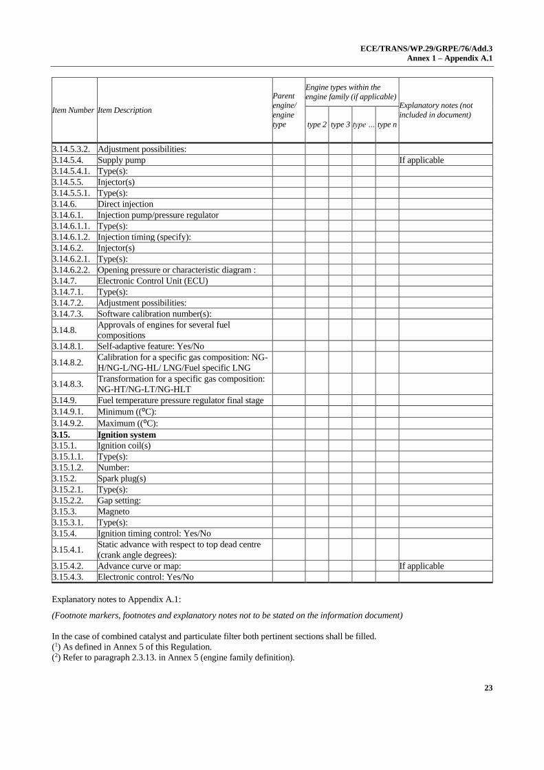
3.14.5.4. Supply pump If applicable
3.14.5.4.1. Type(s):
3.14.5.5. Injector(s)
3.14.5.5.1. Type(s):
3.14.6. Direct injection
3.14.6.1. Injection pump/pressure regulator
3.14.6.1.1. Type(s):
3.14.6.1.2. Injection timing (specify):
3.14.6.2. Injector(s)
3.14.6.2.1. Type(s):
3.14.6.2.2. Opening pressure or characteristic diagram :
3.14.7. Electronic Control Unit (ECU)
3.14.7.1. Type(s):
3.14.7.2. Adjustment possibilities:
3.14.7.3. Software calibration number(s):
3.14.8. Approvals of engines for several fuel
compositions
3.14.8.1. Self-adaptive feature: Yes/No
3.14.8.2. Calibration for a specific gas composition: NG-
H/NG-L/NG-HL/ LNG/Fuel specific LNG
3.14.8.3. Transformation for a specific gas composition:
NG-HT/NG-LT/NG-HLT
3.14.9. Fuel temperature pressure regulator final stage
3.14.9.1. Minimum ((⁰C):
3.14.9.2. Maximum ((⁰C):
3.15. Ignition system
3.15.1. Ignition coil(s)
3.15.1.1. Type(s):
3.15.1.2. Number:
3.15.2. Spark plug(s)
3.15.2.1. Type(s):
3.15.2.2. Gap setting:
3.15.3. Magneto
3.15.3.1. Type(s):
3.15.4. Ignition timing control: Yes/No
3.15.4.1. Static advance with respect to top dead centre
(crank angle degrees):
3.15.4.2. Advance curve or map: If applicable
3.15.4.3. Electronic control: Yes/No
Explanatory notes to Appendix A.1:
(Footnote markers, footnotes and explanatory notes not to be stated on the information document)
In the case of combined catalyst and particulate filter both pertinent sections shall be filled.
(1) As defined in Annex 5 of this Regulation.
(2) Refer to paragraph 2.3.13. in Annex 5 (engine family definition).

ECE/TRANS/WP.29/GRPE/76/Add.3
Annex 2
24
Annex 2
Communication
(maximum format: A4 (210 x 297 mm))
1
concerning:2 Approval granted
Approval extended
Approval refused
Approval withdrawn
Production definitively discontinued
of an engine or engine family pursuant to Regulation No. 120
Approval No................................…. Extension No......................................….
Reason for extension/refusal/withdrawal (2): ..........................................................................
SECTION I
1.1. Make (trade name(s) of manufacturer): ..................................................................................
1.2. Commercial name(s) (if applicable): .....................................................................................
1.3. Company name and address of manufacturer: .......................................................................
1.4. Name and address of manufacturer's authorised representative (if any): ..............................
1.5. Name(s) and address(es) of assembly/manufacture plant(s): ................................................
1.6. Engine type designation/engine family designation/FT (2): .................................................
SECTION II
1. Technical service responsible for carrying out the test(s): .....................................................
2. Date(s) of the test report(s): ....................................................................................................
3. Number(s) of the test report(s): ................................................................................................
1 Distinguishing number of the country which has granted/refused/withdrawn approval (see approval
provisions in the Regulation).
2 Strike out which does not apply.
issued by: Name of administration:
......................................
......................................
......................................
ECE/TRANS/WP.29/GRPE/76/Add.3
Annex 2
25
SECTION III
The undersigned hereby certifies the accuracy of the manufacturer's description in the
attached information document of the engine type/engine family (2) described above, for
which one or more representative samples, selected by the approval authority, have been
submitted as prototypes and that the attached test results apply to the engine type/engine
family (2).
1. The engine type/engine family (2) meets/does not meet (2) the requirements laid down in
Regulation 120, 02 series of amendments.
2. The approval is granted/extended/refused/withdrawn (2)
Place: .........................................................................................................................................
Date: ..........................................................................................................................................
Name and signature: .................................................................................................................
Attachments:
Information folder
Test report(s)
All other documents added by the technical services or by the Type Approval Authority
to the information folder in the course of carrying out their functions.
Addendum
Approval number: ..........................................................................................................................
PART A — CHARACTERISTICS OF THE ENGINE TYPE/ENGINE FAMILY (2)
2. Common design parameters of the engine type/engine family (2)
2.1. Combustion Cycle: four stroke cycle/two stroke cycle/rotary/other:
.......................................................................................................... (describe) (2)
2.2. Ignition Type: Compression ignition/spark ignition (2)
2.3.1. Position of the cylinders in the block: V/in-line/radial/other(describe) (2)
2.6 Main Cooling medium: Air/Water/Oil (2)
2.7. Method of air aspiration: naturally aspirated/pressure charged/pressure charged
with charge cooler (2)
2.8.1. Fuel Type(s): Diesel (non-road gas-oil)/Ethanol for dedicated compression
ignition engines (ED95)/Petrol (E10)/ Ethanol (E85)/(Natural
gas/Biomethane)/Liquid Petroleum Gas (LPG) (2)
2.8.1.1. Sub Fuel type (Natural gas/Biomethane only): Universal fuel — high calorific
fuel (H-gas) and low calorific fuel (L-gas)/Restricted fuel — high calorific fuel
(H-gas)/Restricted fuel — low calorific fuel (L-gas)/Fuel specific (LNG);
2.8.2. Fuelling arrangement: Liquid-fuel only/Gaseous-fuel only/Dual-fuel type
1A/Dual-fuel type 1B/Dual-fuel type 2A/Dual-fuel type 2B/Dual-fuel type
3B (2)
2.8.3. List of additional fuels compatible with use by the engine declared by the
manufacturer in accordance with paragraph 5.2.3. of this Regulation (provide

ECE/TRANS/WP.29/GRPE/76/Add.3
Annex 2
26
reference to recognised standard or specification):
............................................................
2.8.4. Lubricant added to fuel: Yes/No (2)
2.8.5. Fuel supply type: Pump (high pressure) line and injector/in-line pump or
distributor pump/Unit injector/ Common rail/Carburettor)/port injector/direct
injector/Mixing unit/other(specify) (2)
2.9. Engine management systems: mechanical/electronic control strategy (2)
2.10. Miscellaneous devices: Yes/No (2)
2.10.1. Exhaust gas recirculation (EGR): Yes/No (2)
2.10.2. Water injection: Yes/No (2)
2.10.3. Air injection: Yes/No (2)
2.10.4. Others (specify): ...................................................................................................
2.11. Exhaust after-treatment system: Yes/No (2)
2.11.1. Oxidation catalyst: Yes/No (2)
2.11.2. De NOX system with selective reduction of NOX (addition of reducing agent):
Yes/No (2)
2.11.3. Other De NOX systems: Yes/No (2)
2.11.4. Three-way catalyst combining oxidation and NOx reduction: Yes/No (2)
2.11.5. Particulate after-treatment system with passive regeneration: Yes/No (2)
2.11.6. Particulate after-treatment system with active regeneration: Yes/No (2)
2.11.7. Other particulate after-treatment systems: Yes/No (2)
2.11.8. Three-way catalyst combining oxidation and NOX reduction: Yes/No (2)
2.11.9. Other after-treatment devices (specify): ................................................................
3. Essential characteristics of the engine type(s)
Item
Number Item Description
Parent Engine
/ Engine type
Engine types within the
family (if applicable)
3.1.1. Engine Type Designation:
3.1.2. Engine type designation shown on
engine mark: Yes/No(2)
3.1.3. Location of the manufacturer's
statutory marking:
3.2.1. Declared rated speed (rpm):
3.2.1.2. Declared rated net Power (kW):
3.2.2. Maximum power speed (rpm):
3.2.2.2. Maximum net power (kW):
3.2.3. Declared maximum torque speed
(rpm):

ECE/TRANS/WP.29/GRPE/76/Add.3
Annex 2
27
Item
Number Item Description
Parent Engine
/ Engine type
Engine types within the
family (if applicable)
3.2.3.2. Declared maximum torque (Nm):
3.6.3. Number of Cylinders:
3.6.4. Engine total swept volume (cm3):
3.8.5. Device for recycling crankcase gases:
Yes/No(2)
3.11.3.12. Consumable reagent: Yes/No(2)
3.11.3.12.1. Type and concentration of reagent
needed for catalytic action:
3.11.3.13. NOX sensor(s): Yes/No(2)
3.11.3.14. Oxygen sensor: Yes/No(2)
3.11.4.7. Fuel borne catalyst (FBC): Yes/No(2)
PART B – TEST RESULTS
1. Approved data
1.1. Rated net power: .............................................. kW, at .............................. min-1
1.2. Maximum net power: ....................................... kW, at .............................. min-1
1.3. Maximum net torque: ...................................... Nm, at .............................. min-1
Explanatory notes to Annex 2
(Footnote markers, footnotes and explanatory notes not to be stated on the type-
approval certificate)
(1) Distinguishing number of the contracting party which has
granted/extended/refused/withdrawn an approval.
(2) Strike out the unused options, or only show the used option(s).
ECE/TRANS/WP.29/GRPE/76/Add.3
Annex 2 – Appendix A.1
28
Annex 2 - Appendix A.1
Test Report
A.1.1. General requirements
One test report shall be completed for each tests required for the type-approval.
Each additional (e.g. a second speed on a constant speed engine) or
supplementary test (e.g. another fuel is tested) will require an additional or
supplementary test report.
A.1.2. Explanatory notes on creation of a test report
A.1.2.1. A test report shall contain at least the information set out in paragraph A.1.3.
A.1.2.2. Notwithstanding paragraph A.1.2.1, only those sections or sub-sections
relevant for the particular test and for the particular engine family, engine types
within the engine family or engine type tested need to be stated in the test
report;
A.1.2.3. The test report may contain more information than that requested in paragraph
A.1.2.1 but in any case, shall adhere to the proposed numbering system;
A.1.2.4. Where several options separated by forward slash are given for an entry, the
unused options shall be struck out, or only the used option(s) shall be shown;
A.1.2.5. Where a ‘type’ of a component is requested, the information supplied shall
uniquely identify the component; this may be a list of characteristic, a
manufacturers' name and part or drawing number, a drawing, or a combination
of the aforementioned or other methods that achieves the same result.
A.1.2.6. The test report may be delivered on paper on in an electronic format agreed
between the manufacturer, technical service and Type Approval Authority.
A.1.3 Template for the test report
TEST REPORT FOR NON-ROAD ENGINES
1. General Information
1.1. Make(s) (trade name(s) of manufacturer): .............................................................
1.2. Commercial name(s) (if applicable): .....................................................................
1.3. Company name and address of manufacturer: .....................................................
1.4. Name of technical service: .....................................................................................
1.5. Address of technical service: ................................................................................
1.6. Location of test: ...................................................................................................
1.7. Date of test: .........................................................................................................
1.8. Test report number: ..............................................................................................
1.9. Information document reference number (if available): .......................................
1.10. Test report type: Primary test/additional test/supplementary test
1.10.1. Description of the purpose of the test: ...................................................................

ECE/TRANS/WP.29/GRPE/76/Add.3
Annex 2 – Appendix A.1
29
2. General engine information (test engine)
2.1. Engine type designation/engine family designation/FT: .......................................
2.2. Engine identification number: ...............................................................................
3. Documentation and information Check list (primary test only)
3.6. For engine types and engine families that use an ECU as part of the engine
control system anti-tampering declaration documentation reference:
.................................................................................................................................
3.7. For engine types and engine families that use mechanical devices as part of the
engine control system anti- tampering and adjustable parameters declaration
and demonstration documentation reference: ........................................................
4. Reference fuel(s) used for test (complete relevant subparagraph(s))
4.1. Liquid fuel for spark-ignition engines
4.1.1. Make: ......................................................................................................................
4.1.2. Type: ......................................................................................................................
4.1.3. Octane number RON: ............................................................................................
4.1.4. Octane number MON: ............................................................................................
4.1.5. Ethanol content ( %): ...........................................................................................
4.1.6. Density at 15 ⁰C (kg/m3): ................................................................................
4.2. Liquid fuel for compression-ignition engines
4.2.1. Make: ......................................................................................................................
4.2.2. Type: ......................................................................................................................
4.2.3. Cetane number: .....................................................................................................
4.2.4. Fame content ( %): ................................................................................................
4.2.5. Density at 15 ⁰C (kg/m3): ...............................................................................
4.3. Gaseous fuel — LPG
4.3.1. Make: ...................................................................................................................
4.3.2. Type: ....................................................................................................................
4.3.3. Reference fuel type: Fuel A/Fuel B
4.3.4. Octane number MON: .........................................................................................
4.4. Gaseous fuel- Methane/biomethane
4.4.1. Reference fuel type: GR/G23/G25/G20
4.4.2. Source of reference gas: specific reference fuel/pipeline gas with admixture
4.4.3. For specific reference fuel
4.4.3.1. Make:.......................................................................................................................
4.4.3.2. Type:........................................................................................................................
4.4.4. For pipeline gas with admixture
4.4.4.1. Admixture(s): Carbon dioxide/Ethane/Methane/Nitrogen/Propane
ECE/TRANS/WP.29/GRPE/76/Add.3
Annex 2 – Appendix A.1
30
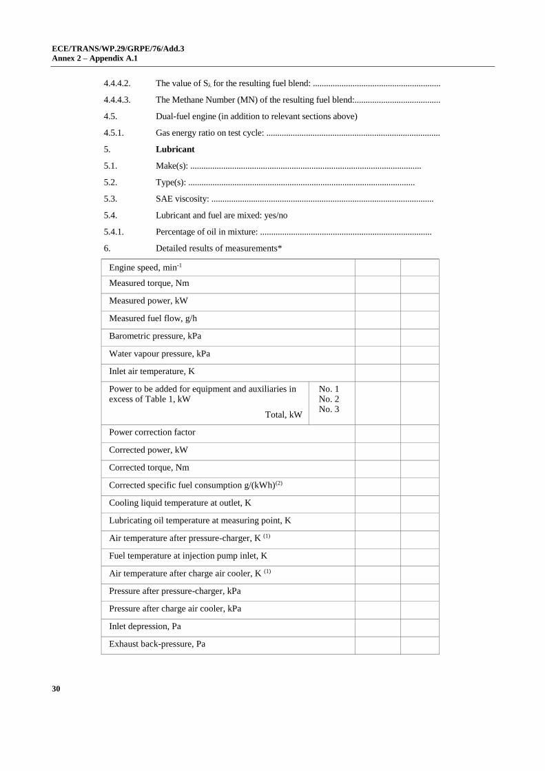
4.4.4.2. The value of Sλ for the resulting fuel blend: ..........................................................
4.4.4.3. The Methane Number (MN) of the resulting fuel blend:.......................................
4.5. Dual-fuel engine (in addition to relevant sections above)
4.5.1. Gas energy ratio on test cycle: ...............................................................................
5. Lubricant
5.1. Make(s): .........................................................................................................
5.2. Type(s): .......................................................................................................
5.3. SAE viscosity: .....................................................................................................
5.4. Lubricant and fuel are mixed: yes/no
5.4.1. Percentage of oil in mixture: ..............................................................................
6. Detailed results of measurements*
Engine speed, min-1
Measured torque, Nm
Measured power, kW
Measured fuel flow, g/h
Barometric pressure, kPa
Water vapour pressure, kPa
Inlet air temperature, K
Power to be added for equipment and auxiliaries in excess of Table 1, kW
Total, kW
No. 1 No. 2 No. 3
Power correction factor
Corrected power, kW
Corrected torque, Nm
Corrected specific fuel consumption g/(kWh)(2)
Cooling liquid temperature at outlet, K
Lubricating oil temperature at measuring point, K
Air temperature after pressure-charger, K (1)
Fuel temperature at injection pump inlet, K
Air temperature after charge air cooler, K (1)
Pressure after pressure-charger, kPa
Pressure after charge air cooler, kPa
Inlet depression, Pa
Exhaust back-pressure, Pa

ECE/TRANS/WP.29/GRPE/76/Add.3
Annex 2 – Appendix A.1
31
Engine speed, min-1
Fuel delivery, mm3/stroke or cycle (1)
* The characteristic curves of the net power and the net torque shall be drawn as a function of the engine speed.
(1) Strike out what does not apply. (2) Calculated with the net power for compression-ignition and positive-ignition engines, in the
latter case multiplied by the power correction factor.

ECE/TRANS/WP.29/GRPE/76/Add.3
Annex 3
32
Annex 3
Arrangements of approval marks
Model A
(see paragraph 4.4. of this Regulation)
a = 8 mm min.
The above approval mark affixed to an engine shows that the engine type concerned
has been approved in the Netherlands (E4) with regard to the measurement of the net
power, pursuant to Regulation No. 120 and under the approval number 021628. The
approval number indicates that the approval was granted in accordance with the
requirements of Regulation No. 120 as amended by the 02 series of amendments.
Model B
(see paragraph 4.5. of this Regulation)
a = 8 mm min.
The above approval mark affixed to an engine shows that the engine type concerned
has been approved in the Netherlands (E4) pursuant to Regulations No. 120 and 961. The
first two digits of the approval numbers indicate that, at the dates when the respective
approvals were granted, Regulation No. 120 was amended by the 02 series of amendments,
and Regulation No. 96 already included the 05 series of amendments.
1 The second number is given merely as an example.
021628
a 2
a 3
E4 a a
3 a 3
a 2
a 2 120
96 051857 EC4/P
E4 a 120 R - 021628 a
3
a 3
a 2
ECE/TRANS/WP.29/GRPE/76/Add.3
Annex 4
33
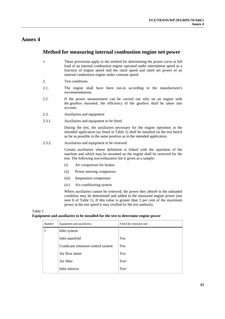
Annex 4
Method for measuring internal combustion engine net power
1. These provisions apply to the method for determining the power curve at full
load of an internal combustion engine operated under intermittent speed as a
function of engine speed and the rated speed and rated net power of an
internal combustion engine under constant speed.
2. Test conditions
2.1. The engine shall have been run-in according to the manufacturer's
recommendations.
2.2. If the power measurement can be carried out only on an engine with
the gearbox mounted, the efficiency of the gearbox shall be taken into
account.
2.3. Auxiliaries and equipment
2.3.1. Auxiliaries and equipment to be fitted
During the test, the auxiliaries necessary for the engine operation in the
intended application (as listed in Table 1) shall be installed on the test bench
as far as possible in the same position as in the intended application.
2.3.2. Auxiliaries and equipment to be removed
Certain auxiliaries whose definition is linked with the operation of the
machine and which may be mounted on the engine shall be removed for the
test. The following non-exhaustive list is given as a sample:
(i) Air compressor for brakes
(ii) Power steering compressor
(iii) Suspension compressor
(iv) Air-conditioning system
Where auxiliaries cannot be removed, the power they absorb in the unloaded
condition may be determined and added to the measured engine power (see
note h of Table 1). If this value is greater than 3 per cent of the maximum
power at the test speed it may verified by the test authority.
Table 1
Equipment and auxiliaries to be installed for the test to determine engine power
Number Equipment and auxiliaries Fitted for emission test
1 Inlet system
Inlet manifold Yes
Crankcase emission control system Yes
Air flow meter Yes
Air filter Yesa
Inlet silencer Yesa

ECE/TRANS/WP.29/GRPE/76/Add.3
Annex 4
34
Number Equipment and auxiliaries Fitted for emission test
2 Exhaust system
Exhaust aftertreatment Yes
Exhaust manifold Yes
Connecting pipes Yesb
Silencer Yesb
Tail pipe Yesb
Exhaust brake Noc
Pressure charging device Yes
3 Fuel supply pump Yesd
4 Carburation equipment
Carburettor Yes
Electronic control system, air flow
meter, etc.
Yes
Equipment for gas engines
Pressure reducer Yes
Evaporator Yes
Mixer Yes
5 Fuel injection equipment (petrol and
diesel)
Pre-filter Yes
Filter Yes
Pump Yes
High-pressure pipe Yes
Injector Yes
Electronic control system, sensors,
etc.
Yes
Governor/control system Yes
Automatic full-load stop for the
control rack depending on
atmospheric conditions
Yes
6 Liquid-cooling equipment
Radiator No
Fan No

ECE/TRANS/WP.29/GRPE/76/Add.3
Annex 4
35
Number Equipment and auxiliaries Fitted for emission test
Fan cowl No
Water pump Yese
Thermostat Yesf
7 Air cooling
Cowl Nog
Fan or Blower Nog
Temperature-regulating device No
8 Pressure charging equipment
Compressor driven either directly by
the engine and/or by the exhaust
gases
Yes
Charge air cooler Yesg, h
Coolant pump or fan (engine-driven) Nog
Coolant flow control device Yes
9 Auxiliary test-bed fan Yes, if necessary
10 Anti-pollution device Yes,
11 Starting equipment Yes or test bed equipmentk
12 Lubricating oil pump Yes
13 Certain auxiliaries whose definition
is linked with the operation of the
non-road mobile machinery and
which may be mounted on the
engine shall be removed for the test.
The following non-exhaustive list is
given as an example:
(i) air compressor for brakes
(ii) power steering compressor
(iii) suspension compressor
(iv) air-conditioning system.
No
a The complete inlet system shall be fitted as provided for the intended application:
(i) Where there is a risk of an appreciable effect on the engine power;
(ii) In the case of naturally aspirated spark ignition engines.
In other cases, an equivalent system may be used and a check should be made to ascertain that
the intake pressure does not differ by more than 100 Pa from the upper limit specified by the
manufacturer for a clean air filter. b The compete exhaust system shall be fitted as provided for the intended application:
(i) Where there is a risk of an appreciable effect on the engine power;
(ii) In the case of naturally aspirated spark ignition engines.
ECE/TRANS/WP.29/GRPE/76/Add.3
Annex 4
36
In other cases, an equivalent system may be installed provided the pressure measured does not
differ by more than 1,000 Pa from the upper limit specified by the manufacturer. c If an exhaust brake is incorporated in the engine, the throttle valve shall be fixed in the fully
open position. d The fuel feed pressure may be adjusted, if necessary, to reproduce the pressure existing in the
particular engine application (particularly when a "fuel return" system is used). e The cooling-liquid circulation shall be operated by the engine water pump only. Cooling of the
liquid may be produced by an external circuit, such that the pressure loss of this circuit and the
pressure at the pump inlet remain substantially the same as those of the engine cooling system. f The thermostat may be fixed in the fully open position. g When the cooling fan or blower is fitted for the test, the power absorbed shall be added to the
results, except for engines where such auxiliaries are an integral part of the engine (i.e.: cooling
fans of air cooled engines directly fitted on the crankshaft). The fan or blower power shall be
determined at the speeds used for the test either by calculation from standard characteristics or
by practical tests. h Charge air-cooled engines shall be tested with charge air cooling, whether liquid - or air-cooled,
but if the manufacturer prefers, a test bench system may replace the air cooler. In either case,
the measurement of power at each speed shall be made with the maximum pressure drop and
the minimum temperature drop of the engine air across the charge air cooler on the test bench
system as those specified by the manufacturer. k The power for electrical or other starting systems shall be provided from the test bed.

ECE/TRANS/WP.29/GRPE/76/Add.3
Annex 4
37
2.4. Setting conditions
The setting conditions for the test to determine the net power are indicated in
Table 2.
Table 2
Setting conditions
1. Setting of carburettor(s), evaporator/pressure regulator
In accordance with the manufacturer's production specifications, and used without further alteration for the particular application.
2. Setting of injection pump delivery system
3. Ignition or injection timing (timing curve)
4. Governor setting
5. Emission control devices
6. Boost Control
3. Data to be recorded
3.1. Data to be recorded are those indicated in appendix A.1 to Annex 2.
Performance data shall be obtained under stabilised operating conditions with
an adequate fresh air supply to the engine. Combustion chambers may
contain deposits, but in limited quantity. Test conditions, such as inlet air
temperature, shall be selected as near to reference conditions
(see paragraph 5.2. of this annex) as possible in order to minimise the
magnitude of the correction factor.
3.2. The temperature of the inlet air to the engine shall be measured within the
inlet ductwork. The inlet depression measurement shall be made at the same
point. The thermometer or thermocouple shall be shielded from fuel spray-
back and radiant heat and located directly in the air stream. A sufficient
number of locations shall be used to give a representative average of the inlet
temperature.
3.3. The inlet depression shall be measured downstream of the entry ducts, air
filter, inlet silencer or speed-limiting device (if fitted).
3.4. The absolute pressure at the entry to the engine downstream
of the compressor and heat exchanger, if fitted, shall be measured in the inlet
manifold and at any other point where pressure has to be measured to
calculate correction factors.
3.5. The exhaust back pressure shall be measured at a point at least three pipe
diameters downstream from the outlet flange(s) of the exhaust manifold(s)
and downstream at the turbocharger(s), if fitted. The location shall be
specified.
3.6. No data shall be taken until torque, speed and temperatures have been
maintained substantially constant for at least one minute.
3.7. The engine speed during a run or reading shall not deviate from the selected
speed by more than 1 per cent or ±10 min, whichever is greater.
3.8. Observed brake load, fuel consumption and inlet air temperature data shall be
taken simultaneously and shall be the average of two stabilised consecutive
values which do not vary more than 2 per cent for the brake load.

ECE/TRANS/WP.29/GRPE/76/Add.3
Annex 4
38
3.9. The temperature of the coolant at the outlet from the engine shall be kept at
the value specified by the manufacturer.
If no temperature is specified by the manufacturer, the temperature shall be
353 K ± 5 K. For air-cooled engines, the temperature at a point indicated by
the manufacturer shall be kept within +0/-20 K of the maximum value
specified by the manufacturer in the reference conditions.
3.10. For C.I. engines, the fuel temperature shall be measured at the inlet of the
fuel injection pump and maintained within 306 - 316 K (33-43 °C) for
positive-ignition engines the fuel temperature shall be measured as near as
possible to the inlet of the carburettor or assemby of fuel injectors and
maintained within 293–303 K (20-30 °C).
3.11. The temperature of the lubricating oil measured in the oil pump or at the
outlet from the coil cooler, if fitted, shall be maintained within the limits
established by the engine manufacturer.
3.12. An auxiliary regulating system may be used if necessary to maintain the
temperatures within the limits specified in paragraphs 3.9., 3.10. and 3.11.
above of this annex.
4. Accuracy of measurements
4.1. Torque: ±1 per cent of measured torque. The torque measuring system shall
be calibrated to take friction losses into account. The accuracy in the lower
half of the measuring range of the dynamometer bench may be ±2 per cent of
measured torque.
4.2. Engine speed: 0.5 per cent of measured speed.
4.3. Fuel consumption: ±1 per cent of measured consumption.
4.4. Fuel temperature: ±2 K.
4.5. Engine inlet air temperature: ±2 K.
4.6. Barometric pressure: ±100 Pa.
4.7. Depression in inlet system: ±50 Pa.
4.8. Back-pressure in exhaust system: ±200 Pa.
5. Power correction factors
5.1. Definition
The power correction factor is the coefficient to determine the engine power
under the reference atmospheric conditions specified in 5.2. below.
Po = α P
where:
Po is the corrected power (i.e. power under reference atmospheric
conditions)
α is the correction factor (αa or αd)
P is the measured power (test power)
5.2. Reference atmospheric conditions
5.2.1. Temperature (To): 298 K (25 °C)
5.2.2. Dry pressure (Pso): 99 kPa

ECE/TRANS/WP.29/GRPE/76/Add.3
Annex 4
39
The dry pressure is based on a total pressure of 100 kPa and a water vapour
pressure of 1 kPa.
5.3. Test atmospheric conditions
The atmospheric conditions during the test shall be the following:
5.3.1. Temperature (T)
For positive-ignition engines: 288 K < T < 308 K
For compression-ignition engines: 283 K < T < 313 K
5.3.2. Pressure (ps)
90 kPa < ps < 110 kPa
5.4. Determination of correction factor αa and αd 1
5.4.1. Naturally aspirated or pressure-charged positive-ignition engine
The correction factor αa is obtained by applying the formula:
6.02.1
s
a298
T*
p
99α
where:
ps is the total dry atmospheric pressure in kilopascals (kPa); i.e. the total
barometric pressure minus water vapour pressure,
T is the absolute temperature in kelvins (K) of the air drawn in by the
engine.
Conditions to be complied with in the laboratory
For a test to be valid, the correction factor must be such that
0.93 < αa < 1.07
If these limits are exceeded, the corrected value obtained shall be given and
the test conditions (temperature and pressure) precisely stated in the test
report.
5.4.2. Compression-ignition engines - factor αd
The power correction factor (αd) for compression-ignition engines at constant
fuel rate is obtained by applying the formula:
αd = (fa)fm
where:
fa is the atmospheric factor
1 The tests may be carried out in air-conditioned test rooms where the atmospheric conditions may be
controlled.
In the case of engines fitted with automatic air temperature control, if the device is such that at full
load at 25 °C no heated air is added, the test shall be carried out with the device fully closed. If the
device is still operating at 25 °C then the test is made with the device operating normally and the
exponent of the temperature term in the correction factor shall be taken as zero (no temperature
correction).

ECE/TRANS/WP.29/GRPE/76/Add.3
Annex 4
40
fm the characteristic parameter for each type of engine and adjustment
5.4.2.1. Atmospheric factor fa
This factor indicates the effects of environmental conditions (pressure,
temperature and humidity) on the air drawn in by the engine. The
atmospheric factor formula differs according to the type of engine.
5.4.2.1.1. Naturally aspirated and mechanically pressure charged engines
7.0
s
a298
T*
p
99f
5.4.2.1.2. Turbocharged engines with or without charge air cooling
5.10.7
s
a298
T*
p
99f
5.4.2.2. Engine factor fm
fm is a function of qc (fuel flow corrected) as follows:
fm = 0.036 qc - 1.14
and
qc = q/r
Where:
q is the fuel flow in milligram per cycle per litre of total swept volume
(mg/(l.cycle))
r is the pressure ratio of compressor outlet and compressor inlet in case
of multiple turbochargers r represents the total compression ratio (r = 1 for
naturally aspirated engines)
This formula is valid for a value interval of qc included between
37.2 mg/(l.cycle) and 65 mg/(l.cycle).
For qc values lower than 37.2 mg/(l.cycle), a constant value of fm equal to 0.2
(fm = 0.2) will be taken.
For qc values higher than 65 mg/(l.cycle), a constant value of fm equal to 1.2
(fm = 1.2) will be taken (see figure):

ECE/TRANS/WP.29/GRPE/76/Add.3
Annex 4
41
5.4.2.3. Conditions to be complied with in the laboratory
For a test to be valid, the correction factors αa must be such that
0.93 < αa < 1.07
If these limits are exceeded, the corrected value obtained shall be given and
the test conditions (temperature and pressure) precisely stated in the test
report

ECE/TRANS/WP.29/GRPE/76/Add.3
Annex 5
42
Annex 5
Parameters for the definition of engine types and engine families, and their operation modes
1. Engine type
The technical features of an engine type shall be those defined in its
information document drafted in accordance with the template set out in
Annex 1.
1.1. Operating mode (speed operation)
An engine type may be type-approved as a constant speed engine or as a
variable speed engine, as defined respectively in paragraphs 2.3. and 2.32. of
this Regulation.
2. Engine family criteria
2.1. General
An engine family is characterised by design parameters. These shall be
common to all engines within the engine family. The engine manufacturer
may decide, which engines belong to an engine family, as long as the
membership criteria listed in paragraph 2.3 of this Annex are respected. The
engine family shall be approved by the Type Approval Authority.
2.2. Engine categories, operating mode (speed operation) and power range.
2.2.1. The engine family shall comprise only engine types of the same speed
operation.
2.3. Parameters defining the engine family
2.3.1. Combustion cycle
(a) 2-stroke cycle;
(b) 4-stroke cycle;
(c) Rotary engine;
(d) Others.
2.3.2. Configuration of the cylinders
2.3.2.1. Position of the cylinders in the block
(a) Single
(b) V;
(c) In-line;
(d) Opposed;
(e) Radial;
(f) Others (F, W, etc.).
2.3.2.2. Relative position of the cylinders
Engines with the same block may belong to the same engine family as long
as their bore centre-to-centre dimensions are the same.

ECE/TRANS/WP.29/GRPE/76/Add.3
Annex 5
43
2.3.3. Main cooling medium
(a) Air;
(b) Water;
(c) Oil.
2.3.4. Swept volume per cylinder
2.3.4.1. Engine with a swept volume per cylinder ≥ 750 cm3
In order for engines with a swept volume per cylinder of ≥ 750 cm3 to be
considered to belong to the same engine family, the spread of the swept
volume per cylinder shall not exceed 15 per cent of the largest swept volume
per cylinder within the engine family.
2.3.4.2. Engine with a swept volume per cylinder < 750 cm3
In order for engines with a swept volume per cylinder of < 750 cm3 to be
considered to belong to the same engine family, the spread of the swept
volume per cylinder shall not exceed 30 per cent of the largest swept volume
per cylinder within the engine family.
2.3.5. Method of air aspiration
(a) Naturally aspirated;
(b) Pressure charged;
(c) Pressure charged with charge cooler.
2.3.6. Fuel type
(a) Diesel (non-road gas-oil);
(b) Ethanol for dedicated compression ignition engines (ED95);
(c) Petrol (E10);
(d) Ethanol (E85);
(e) Natural gas/Biomethane:
(1) Universal fuel — high calorific fuel (H-gas) and low calorific
fuel (L-gas);
(2) Restricted fuel — high calorific fuel (H-gas);
(3) Restricted fuel — low calorific fuel (L-gas);
(4) Fuel specific (LNG);
(f) Liquid Petroleum Gas (LPG);
2.3.7. Fuelling arrangement
(a) Liquid-fuel only;
(b) Gaseous-fuel only;
(c) Dual-fuel type 1A;
(d) Dual-fuel type 1B;
(e) Dual-fuel type 2A;
(f) Dual-fuel type 2B;
(g) Dual-fuel type 3B.

ECE/TRANS/WP.29/GRPE/76/Add.3
Annex 5
44
2.3.8. Combustion chamber type/design
(a) Open chamber;
(b) Divided chamber;
(c) Other types.
2.3.9. Ignition Type
(a) Spark ignition;
(b) Compression ignition.
2.3.10. Valves and porting
(a) Configuration;
(b) Number of valves per cylinder.
2.3.11. Fuel supply type
(a) Pump, (high pressure) line and injector;
(b) In-line pump or distributor pump;
(c) Unit injector;
(d) Common rail;
(e) Carburettor;
(f) Port injector;
(g) Direct injector;
(h) Mixing unit;
(i) Other.
2.3.12. Miscellaneous devices
(a) Exhaust gas recirculation (EGR);
(b) Water injection;
(c) Air injection;
(d) Others.
2.3.13. Electronic control strategy
The presence or absence of an ECU on the engine is regarded as a basic
parameter of the engine family.
The electronic governing of speed does not need to be in a different engine
family from those with mechanical governing. The need to separate
electronic engines from mechanical engines should only apply to the fuel
injection characteristics, such as timing, pressure, rate shape, etc.
2.3.14. Exhaust after-treatment systems
The function and combination of the following devices are regarded as
membership criteria for an engine family:
(a) Oxidation catalyst;
(b) DeNOX system with selective reduction of NOX (addition of reducing
agent);
(c) Other DeNOX systems;

ECE/TRANS/WP.29/GRPE/76/Add.3
Annex 5
45
(d) Particulate after-treatment system with passive regeneration:
(1) wall-flow;
(2) non-wall-flow;
(e) Particulate after-treatment system with active regeneration:
(1) wall-flow;
(2) non-wall-flow;
(f) Other particulate after-treatment systems;
(g) Other devices.
2.3.15. Dual-fuel engines
All engine types within a dual-fuel engine family shall belong to the same
type of dual-fuel engines as defined in paragraph 2 of Annex 7 of 05 series of
amendments to Regulation No. 96, and operate with the same types of fuel or
when appropriate with fuels declared according to this Regulation as being of
the same range(s).
3. Choice of the parent engine
3.1. General
3.1.1. Once the engine family has been agreed by the Type Approval Authority, the
parent engine of the engine family shall be selected using the primary
criterion of the highest fuel delivery per stroke per cylinder at the declared
maximum torque speed. In the event that two or more engines share this
primary criterion, the parent engine shall be selected using the secondary
criterion of highest fuel delivery per stroke at rated speed.

ECE/TRANS/WP.29/GRPE/76/Add.3
Annex 6
46
Annex 6
Checks on conformity of production
1. General
These requirements are consistent with tests to be held to check conformity
of production (COP), according to paragraph 6.2. of this Regulation.
2. Test procedures
The methods of testing and measuring instruments shall be those described in
Annex 4 to this Regulation.
3. Collection of samples
3.1. Case of an engine type
One engine has to be chosen. If after the test of paragraph 4. below, the
engine is not considered as conforming to the requirements of this
Regulation, two more engines have to be tested.
3.2. Case of a family of engines
In case of an approval granted to a family of engines the COP shall be run on
one member of the family, which is not the parent engine. In case of failure
of the COP test, the two more engines shall be of the same member type.
4. Measurement criteria
4.1. Net power and specific fuel consumption of internal combustion engine
Measurements shall be taken at a sufficient number of engine speeds to
define correctly the power, torque and specific fuel consumption curves
between the lowest and the highest engine speeds recommended by the
manufacturer.
The corrected values measured for the engine sampled shall not differ by
more than the values indicated in the table below and ±10 per cent for the
specific fuel consumption.
Engine type
Reference power
(torque) [%]
Other measurement points
on the curve [%]
Tolerance for engine
speed [%]
General ±5 ±10 ±5
Petrol fuelled spark ignited
engines with governor ±8 ±12 ±8
Petrol fuelled spark ignited
engines without governor ±8 ±20 ±8
5. Evaluation of results
If the net power and fuel consumption figures of the second and/or third
engine of paragraph 3. do not fulfil the requirements of paragraph 4. above,
the production shall be considered not to conform to the requirements of this
Regulation and the provision of paragraph 7. of this Regulation shall be put
into effect.

ECE/TRANS/WP.29/GRPE/76/Add.3
Annex 7
47
Annex 7
Technical characteristics of reference fuels prescribed for approval tests and to verify conformity of production
1. Technical data on fuels for testing compression-ignition engines
1.1. Type: Diesel (non-road gas-oil)
Parameter Unit Limits1 Test Method
minimum maximum
Cetane number2 45 56.0 EN-ISO 5165
Density at 15 °C kg/m3 833 865 EN-ISO 3675
Distillation:
50 per cent point °C 245 - EN-ISO 3405
95 per cent point °C 345 350 EN-ISO 3405
Final boiling point °C - 370 EN-ISO 3405
Flash point °C 55 - EN 22719
CFPP °C - –5 EN 116
Viscosity at 40 °C mm2/s 2.3 3.3 EN-ISO 3104
Polycyclic aromatic
hydrocarbons % m/m 2.0 6.0 IP 391
Sulphur content3 mg/kg - 10 ASTM D 5453
Copper corrosion - class 1 EN-ISO 2160
Conradson carbon
residue (10 % DR) % m/m - 0.2 EN-ISO 10370
Ash content % m/m - 0.01 EN-ISO 6245
Total contamination mg/kg - 24 EN 12662
Water content % m/m - 0.02 EN-ISO 12937
Neutralisation (strong
acid) number mg KOH/g - 0.10 ASTM D 974
Oxidation stability3 mg/ml - 0.025 EN-ISO 12205
Lubricity (HFRR wear
scar diameter at 60 °C) μm - 400 CEC F-06-A-96
Oxidation stability at
110 °C3 H 20.0 - EN 15751
FAME % v/v - 7.0 EN 14078 1 The values quoted in the specifications are "true values". In establishment of their limit values the terms of ISO
4259 "Petroleum products – Determination and application of precision data in relation to methods of test" have
been applied and in fixing a minimum value, a minimum difference of 2R above zero has been taken into account;
in fixing a maximum and minimum value, the minimum difference is 4R (R = reproducibility).
Notwithstanding this measure, which is necessary for technical reasons, the manufacturer of fuels should
nevertheless aim at a zero value where the stipulated maximum value is 2R and at the mean value in the case of
quotations of maximum and minimum limits. Should it be necessary to clarify the questions as to whether a fuel
meets the requirements of the specifications, the terms of ISO 4259 should be applied.
2 The range for the cetane number is not in accordance with the requirements of a minimum range of 4R.
However, in the case of a dispute between fuel supplier and fuel user, the terms of ISO 4259 may be used to resolve
such disputes provided replicate measurements, of sufficient number to archive the necessary precision, are made in
preference to single determinations.
3 Even though oxidation stability is controlled, it is likely that shelf life will be limited. Advice should be sought from the
supplier as to storage conditions and life.
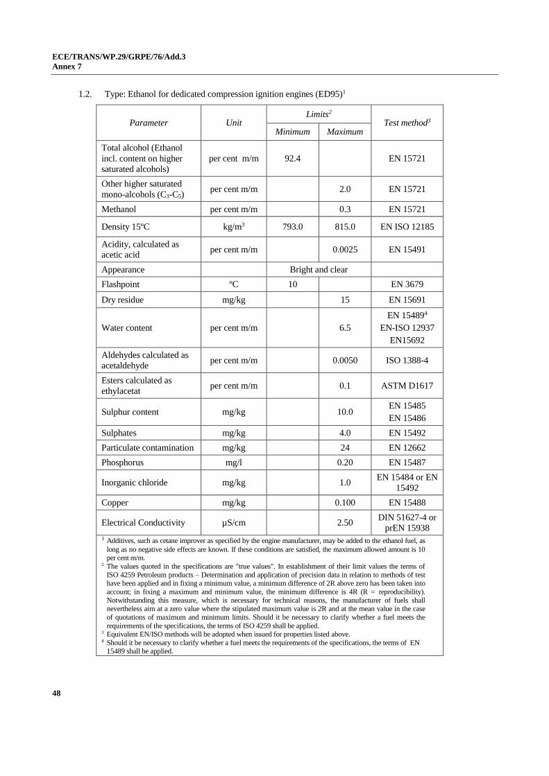
ECE/TRANS/WP.29/GRPE/76/Add.3
Annex 7
48
1.2. Type: Ethanol for dedicated compression ignition engines (ED95)1
Parameter Unit Limits2
Test method3
Minimum Maximum
Total alcohol (Ethanol
incl. content on higher
saturated alcohols)
per cent m/m 92.4 EN 15721
Other higher saturated
mono-alcohols (C3-C5) per cent m/m 2.0 EN 15721
Methanol per cent m/m 0.3 EN 15721
Density 15ºC kg/m3 793.0 815.0 EN ISO 12185
Acidity, calculated as
acetic acid per cent m/m 0.0025 EN 15491
Appearance Bright and clear
Flashpoint ºC 10 EN 3679
Dry residue mg/kg 15 EN 15691
Water content per cent m/m 6.5
EN 154894
EN-ISO 12937
EN15692
Aldehydes calculated as
acetaldehyde per cent m/m 0.0050 ISO 1388-4
Esters calculated as
ethylacetat per cent m/m 0.1 ASTM D1617
Sulphur content mg/kg 10.0 EN 15485
EN 15486
Sulphates mg/kg 4.0 EN 15492
Particulate contamination mg/kg 24 EN 12662
Phosphorus mg/l 0.20 EN 15487
Inorganic chloride mg/kg 1.0 EN 15484 or EN
15492
Copper mg/kg 0.100 EN 15488
Electrical Conductivity µS/cm 2.50 DIN 51627-4 or
prEN 15938 1
Additives, such as cetane improver as specified by the engine manufacturer, may be added to the ethanol fuel, as
long as no negative side effects are known. If these conditions are satisfied, the maximum allowed amount is 10 per cent m/m.
2 The values quoted in the specifications are "true values". In establishment of their limit values the terms of
ISO 4259 Petroleum products – Determination and application of precision data in relation to methods of test have been applied and in fixing a minimum value, a minimum difference of 2R above zero has been taken into
account; in fixing a maximum and minimum value, the minimum difference is 4R (R = reproducibility).
Notwithstanding this measure, which is necessary for technical reasons, the manufacturer of fuels shall nevertheless aim at a zero value where the stipulated maximum value is 2R and at the mean value in the case
of quotations of maximum and minimum limits. Should it be necessary to clarify whether a fuel meets the
requirements of the specifications, the terms of ISO 4259 shall be applied. 3 Equivalent EN/ISO methods will be adopted when issued for properties listed above. 4 Should it be necessary to clarify whether a fuel meets the requirements of the specifications, the terms of EN
15489 shall be applied.

ECE/TRANS/WP.29/GRPE/76/Add.3
Annex 7
49
2. Technical data on fuels for testing spark ignition engines
2.1. Type: Petrol (E10)
Parameter Unit Limits1 Test method2
Minimum Maximum
Research octane
number, RON 91.0 98.0
EN ISO
5164:20053
Motor octane
number, MON 83.0 89.0
EN ISO
5163:20053
Density at 15 °C kg/m3 743 756 EN ISO 3675
EN ISO 12185
Vapour pressure kPa 45.0 60.0 EN ISO 13016-1
(DVPE)
Water content
Max 0.05 per
cent v/v
Appearance
at -7°C: clear
and bright
EN 12937
Distillation:
- evaporated at 70
°C per cent v/v 18.0 46.0 EN-ISO 3405
- evaporated at 100
°C per cent v/v 46.0 62.0 EN-ISO 3405
- evaporated at 150
°C per cent v/v 75.0 94.0 EN-ISO 3405
- final boiling point °C 170 210 EN-ISO 3405
Residue per cent v/v — 2.0 EN-ISO 3405
Hydrocarbon
analysis:
- olefins per cent v/v 3.0 18.0 EN 14517
EN 15553
- aromatics per cent v/v 19.5 35.0 EN 14517
EN 15553
- benzene per cent v/v — 1.0
EN 12177
EN 238, EN
14517
- saturates per cent v/v Report EN 14517
EN 15553
Carbon/hydrogen
ratio Report
Carbon/oxygen ratio Report
Induction period4 minutes 480 EN-ISO 7536
Oxygen content5 per cent m/m 3.38 3.7 EN 1601
EN 13132

ECE/TRANS/WP.29/GRPE/76/Add.3
Annex 7
50
EN 14517
Existent gum mg/ml — 0.04 EN-ISO 6246
Sulphur content6 mg/kg — 10 EN ISO 20846
EN ISO 20884
Copper corrosion
(3h at 50 °C) rating — Class 1 EN-ISO 2160
Lead content mg/l — 5 EN 237
Phosphorus content7 mg/l — 1.3 ASTM D 3231
Ethanol4 per cent v/v 9.08 10.28 EN 22854
Notes: 1 The values quoted in the specifications are "true values". In establishment of their limit values
the terms of ISO 4259 Petroleum products - Determination and application of precision data
in relation to methods of test have been applied and in fixing a minimum value, a minimum
difference of 2R above zero has been taken into account; in fixing a maximum and minimum
value, the minimum difference is 4R (R = reproducibility). Notwithstanding this measure,
which is necessary for technical reasons, the manufacturer of fuels shall nevertheless aim at a
zero value where the stipulated maximum value is 2R and at the mean value in the case of
quotations of maximum and minimum limits. Should it be necessary to clarify whether a fuel
meets the requirements of the specifications, the terms of ISO 4259 shall be applied. 2 Equivalent EN/ISO methods will be adopted when issued for properties listed above. 3 A correction factor of 0.2 for MON and RON shall be subtracted for the calculation of the
final result in accordance with EN 228:2008. 4 The fuel may contain oxidation inhibitors and metal deactivators normally used to stabilise
refinery gasoline streams, but detergent/dispersive additives and solvent oils shall not be
added. 5 Ethanol meeting the specification of EN 15376 is the only oxygenate that shall be
intentionally added to the reference fuel. 6 The actual sulphur content of the fuel used for the Type 1 test shall be reported. 7 There shall be no intentional addition of compounds containing phosphorus, iron, manganese,
or lead to this reference fuel. 8 The ethanol content and corresponding oxygen content may be zero for engines of category
SMB at the choice of the manufacturer. In this case all testing of the engine family, or engine
type where no family exists, shall be conducted using petrol with zero ethanol content.
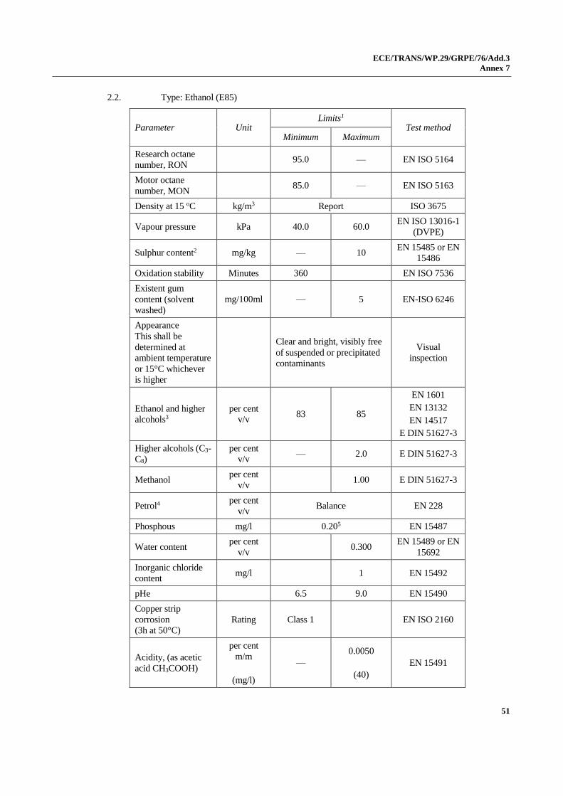
ECE/TRANS/WP.29/GRPE/76/Add.3
Annex 7
51
2.2. Type: Ethanol (E85)
Parameter Unit Limits1
Test method Minimum Maximum
Research octane
number, RON 95.0 — EN ISO 5164
Motor octane
number, MON 85.0 — EN ISO 5163
Density at 15 oC kg/m3 Report ISO 3675
Vapour pressure kPa 40.0 60.0 EN ISO 13016-1
(DVPE)
Sulphur content2 mg/kg — 10 EN 15485 or EN
15486
Oxidation stability Minutes 360 EN ISO 7536
Existent gum
content (solvent
washed)
mg/100ml — 5 EN-ISO 6246
Appearance
This shall be
determined at
ambient temperature
or 15°C whichever
is higher
Clear and bright, visibly free
of suspended or precipitated
contaminants
Visual
inspection
Ethanol and higher
alcohols3
per cent
v/v 83 85
EN 1601
EN 13132
EN 14517
E DIN 51627-3
Higher alcohols (C3-
C8)
per cent
v/v — 2.0 E DIN 51627-3
Methanol per cent
v/v 1.00 E DIN 51627-3
Petrol4 per cent
v/v Balance EN 228
Phosphous mg/l 0.205 EN 15487
Water content per cent
v/v 0.300
EN 15489 or EN
15692
Inorganic chloride
content mg/l 1 EN 15492
pHe 6.5 9.0 EN 15490
Copper strip
corrosion
(3h at 50°C)
Rating Class 1 EN ISO 2160
Acidity, (as acetic
acid CH3COOH)
per cent
m/m
(mg/l)
—
0.0050
(40)
EN 15491
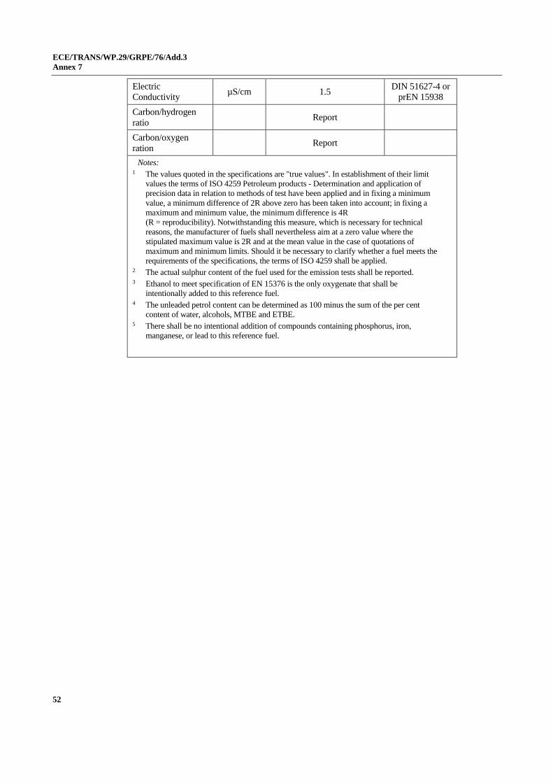
ECE/TRANS/WP.29/GRPE/76/Add.3
Annex 7
52
Electric
Conductivity µS/cm 1.5
DIN 51627-4 or
prEN 15938
Carbon/hydrogen
ratio Report
Carbon/oxygen
ration Report
Notes: 1 The values quoted in the specifications are "true values". In establishment of their limit
values the terms of ISO 4259 Petroleum products - Determination and application of
precision data in relation to methods of test have been applied and in fixing a minimum
value, a minimum difference of 2R above zero has been taken into account; in fixing a
maximum and minimum value, the minimum difference is 4R
(R = reproducibility). Notwithstanding this measure, which is necessary for technical
reasons, the manufacturer of fuels shall nevertheless aim at a zero value where the
stipulated maximum value is 2R and at the mean value in the case of quotations of
maximum and minimum limits. Should it be necessary to clarify whether a fuel meets the
requirements of the specifications, the terms of ISO 4259 shall be applied. 2 The actual sulphur content of the fuel used for the emission tests shall be reported. 3 Ethanol to meet specification of EN 15376 is the only oxygenate that shall be
intentionally added to this reference fuel. 4 The unleaded petrol content can be determined as 100 minus the sum of the per cent
content of water, alcohols, MTBE and ETBE. 5 There shall be no intentional addition of compounds containing phosphorus, iron,
manganese, or lead to this reference fuel.

ECE/TRANS/WP.29/GRPE/76/Add.3
Annex 7
53
3. Technical data on gaseous fuels for single-fuel and dual-fuel engines
3.1. Type: LPG
Parameter Unit Fuel A Fuel B Test
method
Composition: EN 27941
C3-content per cent v/v 30 ± 2 85 ± 2
C4-content per cent v/v Balance1 Balance1
< C3 , > C4 per cent v/v Maximum 2 Maximum 2
Olefins per cent v/v Maximum 12 Maximum 15
Evaporation
residue mg/kg Maximum 50 Maximum 50 EN 15470
Water at 0 °C Free Free EN 15469
Total sulphur
content including
odorant
mg/kg Maximum 10 Maximum 10
EN 24260,
ASTM D
3246,
ASTM
6667
Hydrogen sulphide None None EN ISO
8819
Copper strip
corrosion
(1h at 40 °C)
Rating Class 1 Class 1 ISO 62512
Odour Characteristic Characteristic
Motor octane
number3 Minimum
89.0
Minimum
89.0
EN 589
Annex B
Notes: 1 Balance shall be read as follows: balance = 100 - C3 - <C3 - >C4. 2 This method may not accurately determine the presence of corrosive materials if the sample
contains corrosion inhibitors or other chemicals which diminish the corrosivity of the sample to
the copper strip. Therefore, the addition of such compounds for the sole purpose of biasing the
test method is prohibited. 3 At the request of the engine manufacturer, a higher MON could be used to perform the type
approval tests.
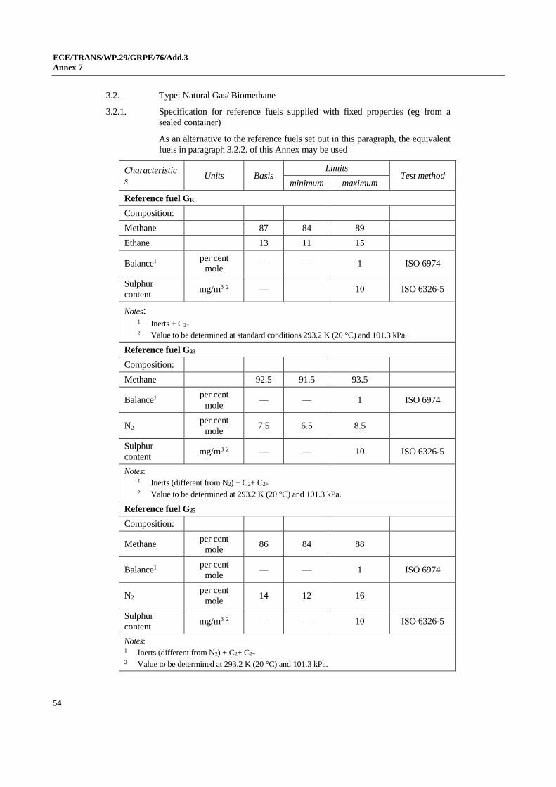
ECE/TRANS/WP.29/GRPE/76/Add.3
Annex 7
54
3.2. Type: Natural Gas/ Biomethane
3.2.1. Specification for reference fuels supplied with fixed properties (eg from a
sealed container)
As an alternative to the reference fuels set out in this paragraph, the equivalent
fuels in paragraph 3.2.2. of this Annex may be used
Characteristic
s Units Basis
Limits Test method
minimum maximum
Reference fuel GR
Composition:
Methane 87 84 89
Ethane 13 11 15
Balance1 per cent
mole — — 1 ISO 6974
Sulphur
content mg/m3 2 — 10 ISO 6326-5
Notes: 1 Inerts + C2+ 2 Value to be determined at standard conditions 293.2 K (20 °C) and 101.3 kPa.
Reference fuel G23
Composition:
Methane 92.5 91.5 93.5
Balance1 per cent
mole — — 1 ISO 6974
N2 per cent
mole 7.5 6.5 8.5
Sulphur
content mg/m3 2 — — 10 ISO 6326-5
Notes: 1 Inerts (different from N2) + C2+ C2+ 2 Value to be determined at 293.2 K (20 °C) and 101.3 kPa.
Reference fuel G25
Composition:
Methane per cent
mole 86 84 88
Balance1 per cent
mole — — 1 ISO 6974
N2 per cent
mole 14 12 16
Sulphur
content mg/m3 2 — — 10 ISO 6326-5
Notes: 1 Inerts (different from N2) + C2+ C2+ 2 Value to be determined at 293.2 K (20 °C) and 101.3 kPa.

ECE/TRANS/WP.29/GRPE/76/Add.3
Annex 7
55
Reference fuel G20
Composition:
Methane per cent
mole 100 99 100 ISO 6974
Balance (1) per cent
mole — — 1 ISO 6974
N2 per cent
mole ISO 6974
Sulphur
content mg/m3 (2) — — 10 ISO 6326-5
Wobbe Index
(net) MJ/m3 (3) 48.2 47.2 49.2
(1) Inerts (different from N2) + C2 + C2+. (2) Value to be determined at 293.2 K (20 °C) and 101.3 kPa. (3) Value to be determined at 273.2 K (0 °C) and 101.3 kPa.
3.2.2. Specification for reference fuel supplied from a pipeline with admixture of
other gases with gas properties determined by on-site measurement
As an alternative to the reference fuels in this paragraph the equivalent
reference fuels in paragraph 3.2.1. of this Annex may be used.
3.2.2.1. The basis of each pipeline reference fuel (GR, G20, …) shall be gas drawn
from a utility gas distribution network, blended, where necessary to meet the
corresponding lambda-shift (Sλ) specification in Table A.7-1, with an
admixture of one or more of the following commercially (the use of
calibration gas for this purpose shall not be required) available gases:
(a) Carbon dioxide;
(b) Ethane;
(c) Methane;
(d) Nitrogen;
(e) Propane.
3.2.2.2. The value of Sλ of the resulting blend of pipeline gas and admixture gas shall
be within the range specified in Table A.7-1 for the specified reference fuel.
Table A.7-1
Required range of Sλ for each reference fuel
Reference fuel Minimum Sλ Maximum Sλ
GR2 0.87 0.95
G20 0.97 1.03
G23 1.05 1.10
G25 1.12 1.20
1 The engine shall not be required to be tested on a gas blend with a Methane Number (MN) less than 70. In
the case that the required range of Sλ for GR would result in an MN less than 70 the value of Sλ for GR may
be adjusted as necessary until a value of MN no less than 70 is attained.

ECE/TRANS/WP.29/GRPE/76/Add.3
Annex 7
56
3.2.2.3. The engine test report for each test run shall include the following:
(a) The admixture gas(es) chosen from the list in paragraph 3.2.2.1. of this
Annex;
(b) The value of Sλ for the resulting fuel blend;
(c) The Methane Number (MN) of the resulting fuel blend.
3.2.2.4. The requirements of Appendices A.1 and A.2 shall be met in respect to
determination of the properties of the pipeline and admixture gases, the
determination of Sλ and MN for the resulting gas blend, and the verification
that the blend was maintained during the test.
ECE/TRANS/WP.29/GRPE/76/Add.3
Annex 7 – Appendix A.1
57
Annex 7 - Appendix A.1
Supplementary requirements for conducting engine testing using gaseous reference fuels comprising pipeline gas with admixture of other gases
A.1.1. Method of gas analysis and gas flow measurement
A.1.1.1. For the purpose of this Appendix, where required the composition of the gas
shall be determined by analysis of the gas using gas chromatography according
to EN ISO 6974, or by an alternative technique that achieves at least a similar
level of accuracy and repeatability.
A.1.1.2. For the purpose of this Appendix, where required the measurement of gas flow
shall be performed using a mass-based flowmeter.
A.1.2. Analysis and flowrate of incoming utility gas supply
A.1.2.1. The composition of the utility gas supply shall be analysed prior to the
admixture blending system.
A.1.2.2. The flowrate of the utility gas entering the admixture blending system shall be
measured.
A.1.3. Analysis and flowrate of admixture
A.1.3.1. When an applicable certificate of analysis is available for an admixture (for
example issued by the gas supplier) this may be used as the source of that
admixture composition. In this case the on-site analysis of that admixture
composition shall be permitted but shall not be required.
A.1.3.2. Where an applicable certificate of analysis is not available for an admixture the
composition of that admixture shall be analysed.
A.1.3.3. The flowrate of each admixture entering the admixture blending system shall
be measured.
A.1.4. Analysis of blended gas
A.1.4.1. The analysis of the composition of the gas supplied to the engine after leaving
the admixture blending system shall be permitted in addition to, or as an
alternative to the analysis required by paragraphs A.1.2.1. and A.1.3.1., but
shall not be required.
A.1.5. Calculation of Sλ and MN of the blended gas
A.1.5.1. The results of the gas analysis according to paragraphs A.1.2.1., A.1.3.1. or
A.1.3.2. and, where applicable, paragraph A.1.4.1., combined with the mass
flowrate of gas measured according to paragraphs A.1.2.2. and A.1.3.3., shall
be used to calculate the MN according to EN16726:2015. The same set of data
shall be used to calculate Sλ according to the procedure set out in Appendix A.2
to this Annex.
A.1.6. Control and verification of gas blend during the test
A.1.6.1. The control and verification of the gas blend during the test shall be performed
using either an open loop or closed loop control system.
A.1.6.2. Open loop blend control system

ECE/TRANS/WP.29/GRPE/76/Add.3
Annex 7 – Appendix A.1
58
A.1.6.2.1. In this case the gas analysis, flow measurements and calculations set out in
paragraphs A.1.1., A.1.2., A.1.3. and A.1.4. shall be performed prior to the
emission test.
A.1.6.2.2. The proportion of utility gas and admixture(s) shall be set to ensure that the Sλ
is within the permitted range for the relevant reference fuel in Table A.7-1.
A.1.6.2.3. When the relative proportions have been set they shall be maintained
throughout the engine test. Adjustments to individual flow rates to maintain the
relative proportions shall be permitted.
A.1.6.2.4. When the engine test has been completed the analysis of gas composition, flow
measurements and calculations set out in paragraphs A.1.2., A.1.3., A.1.4. and
A.1.5. shall be repeated. In order for the test to be considered valid the value of
Sλ shall remain within the specified range for the respective reference fuel
given in Table A.7-1.
A.1.6.3. Closed loop blend control system
A.1.6.3.1. In this case the analysis of gas composition, flow measurements and
calculations set out in paragraphs A.1.2., A.1.3., A.1.4. and A.1.5. shall be
performed at intervals during the emission test. The intervals shall be chosen
taking into consideration the frequency capability of the gas chromatograph
and corresponding calculation system.
A.1.6.3.2 The results from the periodic measurements and calculations shall be used to
adjust the relative proportions of utility gas and admixture in order to maintain
the value of Sλ within the range specified in Table A.7-1 for the respective
reference fuel. The frequency of adjustment shall not exceed the frequency of
measurement.
A.1.6.3.3. In order for the test to be considered valid the value of Sλ shall be within the
range specified in Table A.7-1 for the respective reference fuel for at least 90
per cent of the measurement points.

ECE/TRANS/WP.29/GRPE/76/Add.3
Annex 7 – Appendix A.2
59
Annex 7 - Appendix A.2
Calculation of λ-Shift factor (Sλ)
A.2.1. Calculation
The λ-shift factor (Sλ)7 shall be calculated by means of equation (A.7-1):
(A.7-1)
Where:
Sλ = λ-shift factor;
inert per cent = per cent by volume of inert gases in the fuel (i.e. N2, CO2,
He, etc.);
𝑂2∗ = per cent by volume of original oxygen in the fuel;
n and m = refer to average CnHm representing the fuel hydrocarbons, i.e:
(A.7-2)
(A.7-3)
Where:
CH4 = per cent by volume of methane in the fuel;
C2 = per cent by volume of all C2 hydrocarbons (e.g.: C2H6, C2H4,
etc.) in the fuel;
C3 = per cent by volume of all C3 hydrocarbons (e.g.: C3H8, C3H6,
etc.) in the fuel;
C4 = per cent by volume of all C4 hydrocarbons (e.g.: C4H10, C4H8,
etc.) in the fuel;
C5 = per cent by volume of all C5 hydrocarbons (e.g.: C5H12, C5H10,
etc.) in the fuel;
diluent = per cent by volume of dilution gases in the fuel (i.e.: O2*, N2,
CO2, He, etc.).
7 Stoichiometric Air/Fuel ratios of automotive fuels - SAE J1829, June 1987. John B. Heywood, Internal
combustion engine fundamentals, McGraw-Hill, 1988, Chapter 3.4 "Combustion stoichiometry" (pp. 68 to 72).
100
O
4
mn
100
inert%1
2S
*2
λ
100
%diluent 1
..100
%C5
100
%C4
100
%C3
100
%C2
100
%CH1
n
54324
100
%diluent 1
..100
%HC...8
100
%HC6
100
%HC4
100
%CH4
m
8362424

ECE/TRANS/WP.29/GRPE/76/Add.3
Annex 7 – Appendix A.2
60
A.2.2. Examples for the calculation of the λ-shift factor Sλ:
Example 1: G25: CH4 = 86 per cent, N2 = 14 per cent (by volume)
Example 2: GR: CH4 = 87 per cent, C2H6 = 13 per cent (by vol)
Example 3: CH4 = 89 per cent, C2H6 = 4,5 per cent, C3H8 = 2,3 per cent, C6H14
= 0,2 per cent, O2 = 0,6 per cent, N2 = 4 per cent
1 0.86
0.86
100
14 1
0.86 1
100
% diluent 1
.. 100
% C 2
100
% CH 1
n
2 4
4 0.86
0.86 4
100
% diluent 1
.. 100
% H C 4
100
% CH 4
m
4 2 4
1.16
4
4 1
100
14 1
2
100
O
4
m n
100
inert% 1
2 S
* 2
λ
1.13 1.13
100
0 1
0.13 2 0.87 1
100
% diluent 1
.. 100
% C 2
100
% CH 1
n
2 4
4.26 1
0.13 6 0.87 4
100
% diluent 1
.. 100
% H C 4
100
% CH 4
m
4 2 4
0.911
4
4.26 1.13
100
0 1
2
100
O
4
m n
100
inert% 1
2 S
* 2
λ
1.11
100
4 0.64 1
0.002 4 0.023 3 0.045 2 0.89 1
100
% diluent 1
.. 100
% C 2
100
% CH 1
n
2 4
4,24 =
100
4 + 60 1
002014 + 02308 + 04504 +4 =
=
100
% diluent 1
100
%HC8 + .. +
100
%HC6 +
100
%HC4 +
100
%CH4
= m
.
...89.0
8362424
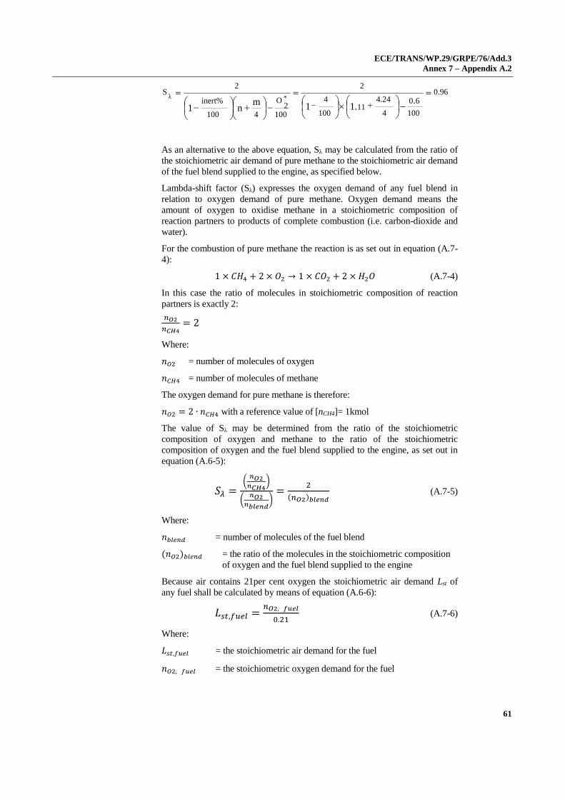
ECE/TRANS/WP.29/GRPE/76/Add.3
Annex 7 – Appendix A.2
61
As an alternative to the above equation, Sλ may be calculated from the ratio of
the stoichiometric air demand of pure methane to the stoichiometric air demand
of the fuel blend supplied to the engine, as specified below.
Lambda-shift factor (Sλ) expresses the oxygen demand of any fuel blend in
relation to oxygen demand of pure methane. Oxygen demand means the
amount of oxygen to oxidise methane in a stoichiometric composition of
reaction partners to products of complete combustion (i.e. carbon-dioxide and
water).
For the combustion of pure methane the reaction is as set out in equation (A.7-
4):
1 × 𝐶𝐻4 + 2 × 𝑂2 → 1 × 𝐶𝑂2 + 2 × 𝐻2𝑂 (A.7-4)
In this case the ratio of molecules in stoichiometric composition of reaction
partners is exactly 2:
𝑛𝑂2
𝑛𝐶𝐻4= 2
Where:
𝑛𝑂2 = number of molecules of oxygen
𝑛𝐶𝐻4 = number of molecules of methane
The oxygen demand for pure methane is therefore:
𝑛𝑂2 = 2 ∙ 𝑛𝐶𝐻4 with a reference value of [nCH4]= 1kmol
The value of Sλ may be determined from the ratio of the stoichiometric
composition of oxygen and methane to the ratio of the stoichiometric
composition of oxygen and the fuel blend supplied to the engine, as set out in
equation (A.6-5):
𝑆𝜆 =(
𝑛𝑂2𝑛𝐶𝐻4
)
(𝑛𝑂2
𝑛𝑏𝑙𝑒𝑛𝑑)
=2
(𝑛𝑂2)𝑏𝑙𝑒𝑛𝑑 (A.7-5)
Where:
𝑛𝑏𝑙𝑒𝑛𝑑 = number of molecules of the fuel blend
(𝑛𝑂2)𝑏𝑙𝑒𝑛𝑑 = the ratio of the molecules in the stoichiometric composition
of oxygen and the fuel blend supplied to the engine
Because air contains 21per cent oxygen the stoichiometric air demand Lst of
any fuel shall be calculated by means of equation (A.6-6):
𝐿𝑠𝑡,𝑓𝑢𝑒𝑙 =𝑛𝑂2, 𝑓𝑢𝑒𝑙
0.21 (A.7-6)
Where:
𝐿𝑠𝑡,𝑓𝑢𝑒𝑙 = the stoichiometric air demand for the fuel
𝑛𝑂2, 𝑓𝑢𝑒𝑙 = the stoichiometric oxygen demand for the fuel
0.96
100
0.6
4
4.24 1.11
100
4 1
2
100
O
4
m n
100
inert% 1
2 S
* 2
λ

ECE/TRANS/WP.29/GRPE/76/Add.3
Annex 7 – Appendix A.2
62
Consequently the value of Sλ may also be determined from the ratio of the
stoichiometric composition of air and methane to the ratio of the stoichiometric
composition of air and the fuel blend supplied to the engine, i.e. the ratio of the
stoichiometric air demand of methane to that of the fuel blend supplied to the
engine, as set out in equation (A.6-7):
𝑆𝜆 =(
𝑛𝑂2𝑛𝐶𝐻4
)/0.21
(𝑛𝑂2
𝑛𝑏𝑙𝑒𝑛𝑑)/0.21
=(
𝑛𝑂20.21
)𝐶𝐻4
(𝑛𝑂20.21
)𝑏𝑙𝑒𝑛𝑑
=𝐿𝑠𝑡,𝐶𝐻4
𝐿𝑠𝑡,𝑏𝑙𝑒𝑛𝑑 (A.7-7)
Therefore, any calculation that specifies the stoichiometric air demand may be
used to express the Lambda-shift factor.