Ecological Boilers VIGAS - AHONA Manual Feb 2010.pdf · Ecological Boilers VIGAS MANUAL FOR...
36
1 Ecological Boilers VIGAS MANUAL FOR INSTALLATION, ASSEMBLY AND USE VIGAS and VIGAS Lambda Control with AK 3000 Certificate of warranty VIMAR 2010
Transcript of Ecological Boilers VIGAS - AHONA Manual Feb 2010.pdf · Ecological Boilers VIGAS MANUAL FOR...
1
Gasifying boilers VIGAS
Ecological Boilers VIGAS
MANUAL FOR INSTALLATION, ASSEMBLY AND USE
VIGAS and VIGAS Lambda Control with AK 3000
Certificate of warranty
VIMAR 2010
2
Gasifying boilers VIGAS
Content Declaration of conformity......................................................................................................1. Technical description......................................................................................................2. Technical data................................................................................................................ 3. Description of AK 3000 control...................................................................................... 4. VIGAS boiler in basic configuration............................................................................... 5. VIGAS boiler in configuration with gases thermometer.................................................. 6. VIGAS boiler in configuration with gases thermometer and discharge fan.................... 7. VIGAS Lambda Control in configuration with gases thermometer..........................................8. VIGAS Lambda Control in configuration with gases thermometer and discharge fan............ 9. Time setting.................................................................................................................... 10. Hardware and software information............................................................................... 11. Error messages.............................................................................................................. 12. Service settings PIN 0000 protected.............................................................................. 13. Operating instructions.....................................................................................................14. Boiler maintainance and repairs.................................................................................... 15. Accesories assembly..................................................................................................... 16. Listo fo guarantee and afterguarantee services............................................................. 17. Problems solving............................................................................................................ 18. Assembly instruction...................................................................................................... 19. Electric scheme of connection VIGAS boilers................................................................ Letter of guarantee......................................................................................................... Confirmation of VIGAS boilers commissioning..............................................................
Page 3 4 5 7 9 11 12 13 15 17 18 18 18 21 24 26 28 28 29 31 32 33
3
Gasifying boilers VIGAS
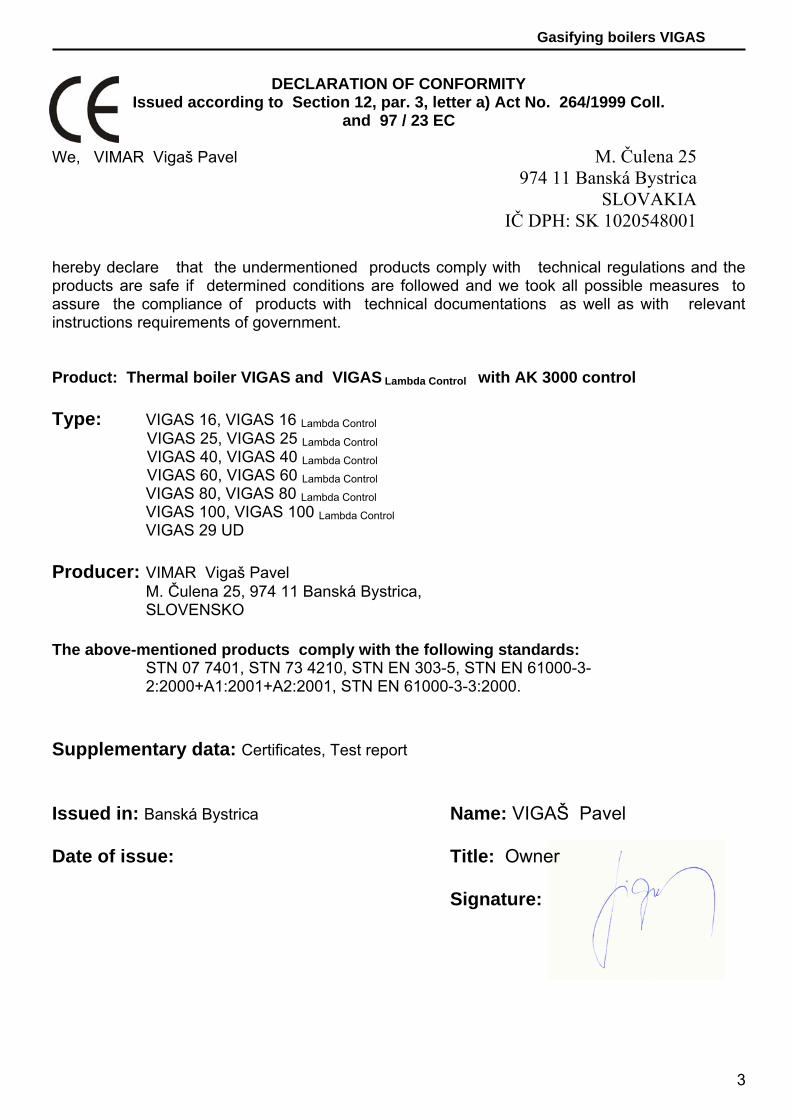
DECLARATION OF CONFORMITY
Issued according to Section 12, par. 3, letter a) Act No. 264/1999 Coll. and 97 / 23 EC
We, VIMAR Vigaš Pavel hereby declare that the undermentioned products comply with technical regulations and the products are safe if determined conditions are followed and we took all possible measures to assure the compliance of products with technical documentations as well as with relevant instructions requirements of government. Product: Thermal boiler VIGAS and VIGAS Lambda Control with AK 3000 control Type: VIGAS 16, VIGAS 16 Lambda Control
VIGAS 25, VIGAS 25 Lambda Control VIGAS 40, VIGAS 40 Lambda Control VIGAS 60, VIGAS 60 Lambda Control
VIGAS 80, VIGAS 80 Lambda Control VIGAS 100, VIGAS 100 Lambda Control VIGAS 29 UD
Producer: VIMAR Vigaš Pavel M. Čulena 25, 974 11 Banská Bystrica, SLOVENSKO The above-mentioned products comply with the following standards: STN 07 7401, STN 73 4210, STN EN 303-5, STN EN 61000-3-
2:2000+A1:2001+A2:2001, STN EN 61000-3-3:2000. Supplementary data: Certificates, Test report
Issued in: Banská Bystrica Name: VIGAŠ Pavel Date of issue: Title: Owner Signature:
M. Čulena 25 974 11 Banská Bystrica
SLOVAKIA IČ DPH: SK 1020548001
4
Gasifying boilers VIGAS
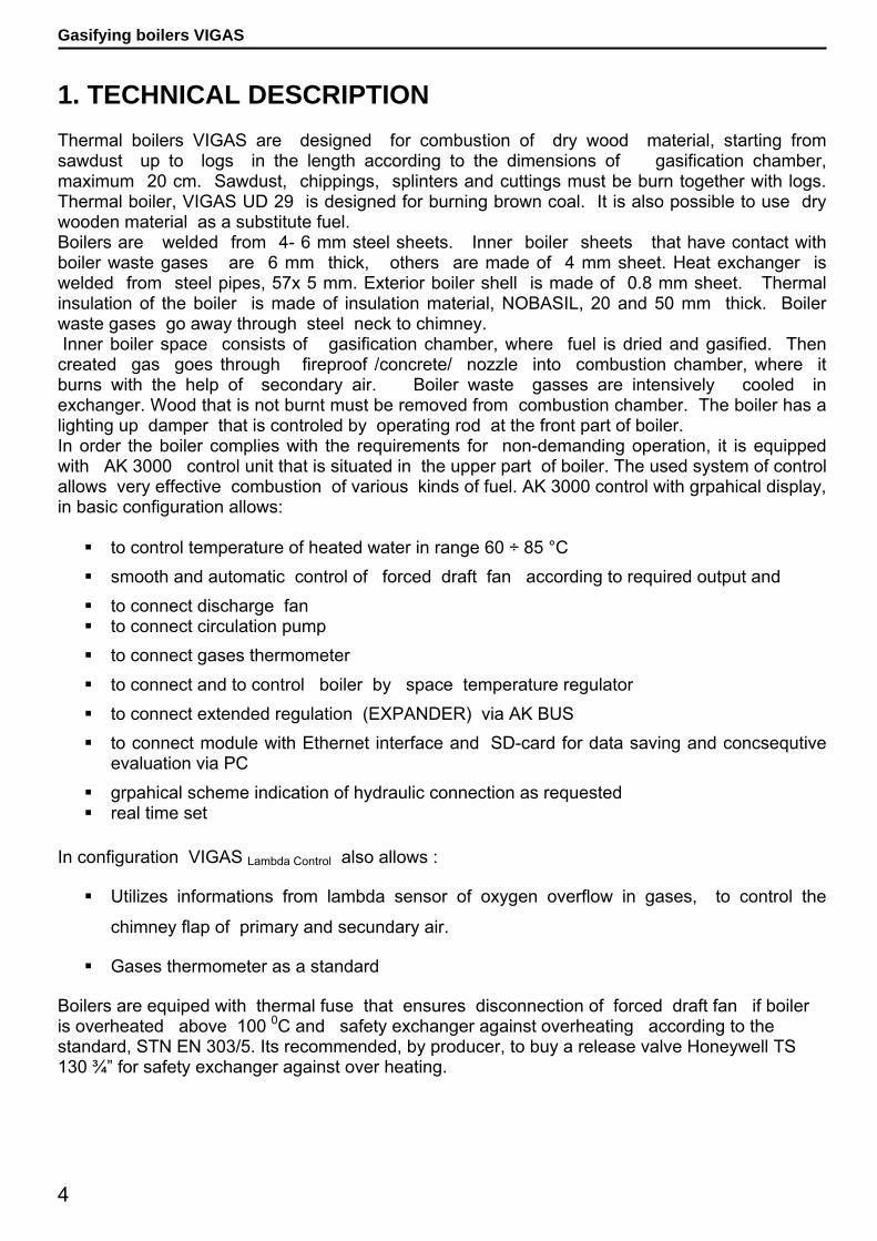
1. TECHNICAL DESCRIPTION Thermal boilers VIGAS are designed for combustion of dry wood material, starting from sawdust up to logs in the length according to the dimensions of gasification chamber, maximum 20 cm. Sawdust, chippings, splinters and cuttings must be burn together with logs. Thermal boiler, VIGAS UD 29 is designed for burning brown coal. It is also possible to use dry wooden material as a substitute fuel. Boilers are welded from 4- 6 mm steel sheets. Inner boiler sheets that have contact with boiler waste gases are 6 mm thick, others are made of 4 mm sheet. Heat exchanger is welded from steel pipes, 57x 5 mm. Exterior boiler shell is made of 0.8 mm sheet. Thermal insulation of the boiler is made of insulation material, NOBASIL, 20 and 50 mm thick. Boiler waste gases go away through steel neck to chimney. Inner boiler space consists of gasification chamber, where fuel is dried and gasified. Then created gas goes through fireproof /concrete/ nozzle into combustion chamber, where it burns with the help of secondary air. Boiler waste gasses are intensively cooled in exchanger. Wood that is not burnt must be removed from combustion chamber. The boiler has a lighting up damper that is controled by operating rod at the front part of boiler. In order the boiler complies with the requirements for non-demanding operation, it is equipped with AK 3000 control unit that is situated in the upper part of boiler. The used system of control allows very effective combustion of various kinds of fuel. AK 3000 control with grpahical display, in basic configuration allows:
to control temperature of heated water in range 60 ÷ 85 °C smooth and automatic control of forced draft fan according to required output and to connect discharge fan to connect circulation pump to connect gases thermometer to connect and to control boiler by space temperature regulator to connect extended regulation (EXPANDER) via AK BUS to connect module with Ethernet interface and SD-card for data saving and concsequtive
evaluation via PC grpahical scheme indication of hydraulic connection as requested real time set
In configuration VIGAS Lambda Control also allows :
Utilizes informations from lambda sensor of oxygen overflow in gases, to control the
chimney flap of primary and secundary air.
Gases thermometer as a standard
Boilers are equiped with thermal fuse that ensures disconnection of forced draft fan if boiler is overheated above 100 0C and safety exchanger against overheating according to the standard, STN EN 303/5. Its recommended, by producer, to buy a release valve Honeywell TS 130 ¾” for safety exchanger against over heating.
5
Gasifying boilers VIGAS
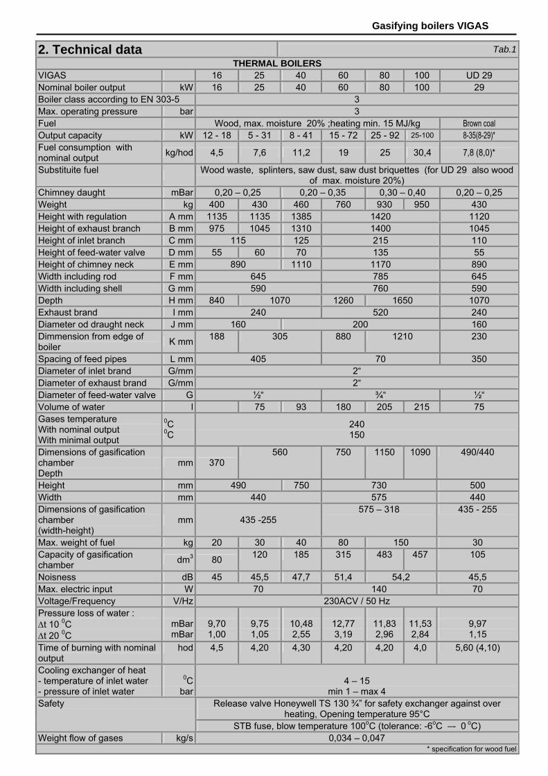
2. Technical data Tab.1THERMAL BOILERS
VIGAS 16 25 40 60 80 100 UD 29 Nominal boiler output kW 16 25 40 60 80 100 29 Boiler class according to EN 303-5 3 Max. operating pressure bar 3 Fuel Wood, max. moisture 20% ;heating min. 15 MJ/kg Brown coal Output capacity kW 12 - 18 5 - 31 8 - 41 15 - 72 25 - 92 25-100 8-35(8-29)* Fuel consumption with nominal output kg/hod 4,5 7,6 11,2 19 25 30,4 7,8 (8,0)*
Substituite fuel Wood waste, splinters, saw dust, saw dust briquettes (for UD 29 also wood of max. moisture 20%)
Chimney daught mBar 0,20 – 0,25 0,20 – 0,35 0,30 – 0,40 0,20 – 0,25 Weight kg 400 430 460 760 930 950 430 Height with regulation A mm 1135 1135 1385 1420 1120 Height of exhaust branch B mm 975 1045 1310 1400 1045 Height of inlet branch C mm 115 125 215 110 Height of feed-water valve D mm 55 60 70 135 55 Height of chimney neck E mm 890 1110 1170 890 Width including rod F mm 645 785 645 Width including shell G mm 590 760 590 Depth H mm 840 1070 1260 1650 1070 Exhaust brand I mm 240 520 240 Diameter od draught neck J mm 160 200 160 Dimmension from edge of boiler K mm 188 305 880 1210 230
Spacing of feed pipes L mm 405 70 350 Diameter of inlet brand G/mm 2“ Diameter of exhaust brand G/mm 2“ Diameter of feed-water valve G ½“ ¾“ ½“ Volume of water l 75 93 180 205 215 75 Gases temperature With nominal output With minimal output
0C 0C
240 150
Dimensions of gasification chamber Depth
mm 370 560 750 1150 1090 490/440
Height mm 490 750 730 500 Width mm 440 575 440 Dimensions of gasification chamber (width-height)
mm 435 -255 575 – 318 435 - 255
Max. weight of fuel kg 20 30 40 80 150 30 Capacity of gasification chamber dm3 80 120 185 315 483 457 105
Noisness dB 45 45,5 47,7 51,4 54,2 45,5 Max. electric input W 70 140 70 Voltage/Frequency V/Hz 230ACV / 50 Hz Pressure loss of water : Δt 10 0C Δt 20 0C
mBar mBar
9,70 1,00
9,75 1,05
10,48 2,55
12,77 3,19
11,83 2,96
11,53 2,84
9,97 1,15
Time of burning with nominal output
hod 4,5 4,20 4,30 4,20 4,20 4,0 5,60 (4,10)
Cooling exchanger of heat - temperature of inlet water - pressure of inlet water
0C bar
4 – 15
min 1 – max 4 Release valve Honeywell TS 130 ¾” for safety exchanger against over
heating, Opening temperature 95°C Safety
STB fuse, blow temperature 100oC (tolerance: -6oC –- 0 oC) Weight flow of gases kg/s 0,034 – 0,047
* specification for wood fuel

6
Gasifying boilers VIGAS 2.1 DIMENSION CHART AND THE POSITION OF PROTECTIVE SUPPORT PLATE ON EASILY IGNITABLE FLOOR
2.2 BOILER SCHEMATICS
Pic.1 Pic.2
KEY 1. AK 3000 control 2. Upper door 3. Chimney flap operating rod 4. Fuel bunker 5. Primary air conduction 6. Flap for Lambda control servo 7. Fan 8. Fan cover 9. Heatproof nozzle 10. Secondary air screen
11. Door closing device 12. Fireclay bricks 13. Bottom door 14. Chimney neck 15. Exchanger cap 16. Lighting up damper 17. Upper back cover 18. Outlet water neck 19. Thermal fuse 20. Thermometer 21. Upper front cover
22. Lambda sensor 23. Gases thermometer 24. Exchanger pipes 25. Heat proof /concrete/ filling 26. Secondary air 27. Combustion chamber 28. Direction of gases 29. Neck of reversible water 30. Fillng neck 31. Cleaning flap for 29UD 32. Cleaning hole for 29UD
Scheme VIGAS 60,80
Scheme VIGAS 25 Scheme VIGAS 40
Scheme VIGAS 100
Scheme VIGAS 16
Scheme VIGAS 29 UD
Pic.3
Inlet water neck for valve (Danfoss)
Hole for submersible case (Danfoss)
Exhaust brand of cooling water
Exhaust water neck
Inlet water neck Filling neck

7
Gasifying boilers VIGAS
3. DESCRIPTION OF AK 3000 CONTROL
3.1 Safety Instructions
Check protection (cover) metal sheet before plug-in the power wire Avoid any contact of power wire with hot parts of the boiler (f.e. chimney) Make sure, no water is allowed under the upper isolation (risk of short circuit) Do not stress the power wire Always disconnect the power wire when a new electrical components are connecting (f.e.
indoor thermostat, discharge fan or circulation pump) Do not remove protection (cover) metal sheet during the boiler operation, especially from
fan Compare working voltage displayed on the label with your distribution network Always observe safety regulations
3.2 Connecting to the distributing network AK 3000 control is integral part of VIGAS boilers. Control is connected when power wire is plugged in to the distributing network 220/230V. Display is active when power wire is plugged-in (Pic.4). Servo-flat used in VIGAS Lambda Control is set to base position (Pic.5). 3.3 Working conditions Operation temperature range of AK 3000 control is +5°C to +45 °C. Control may not be used in humid enviroment or direct sunlight. 3.4 Maintainance of AK 3000 control Keep in clean and dust-free enviroment. Antistatic, or wet wipper is adivsed to wipe-off dust and impurities from metal cover and control panel. 3.5 Control panel Part of the electronic control is panel, equipped with buttons, pictograms and display. Futher informations will be available in the next part of this manual.
Pic.6
Pic.5
1. Graphical display 128 x 64 pixels 2. Button ◄ with functions 3. Button ▲ with functions 4. Button ► with functions 5. Button (ENTER) with functions 6. LED control 7. Button with functions
Pic.4

8
Gasifying boilers VIGAS Functionality of each button are composite and their functionality deppends accompanying description on display and from manufacture settings. 3.6 Symbols
1. Real time indication. 2. Indication of current boiler values. Modification ▲ or . 3. Indication od discharge fan, lambda sensor, gases
thermometer 4. Indication of nominal boiler output when switched off.5. Graphically indicated hydraulic scheme of
connection. 6. Indication of boiler status.
Pic.7
Boiler
Storage tank
External boiler
Boiler „ON“ ON DUOMIX
Heating circuit
Boiler „OFF“ OFF DUOMIX with servomotor
Indoor thermostat
Heating ON
Pump 3-way thermostatic valve
Burning 73 0C
Discharge fan LADOMAT
Afterflaming 52 0C
Lambda λ Fan
End of burning END Thermometer T Fan change
output Indoor termostat decay
Error indication value x Open flap servo 50%
Adding fuel Minimal value of gases min
Maximal value of gases max
Temperature settings
Parameter settings Time setting
Error messages
Program
Konfiguration informations
Service message
9
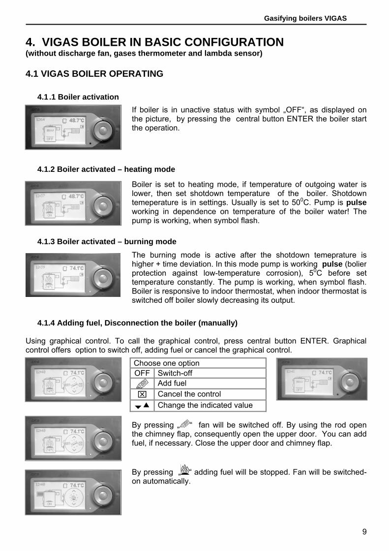
Gasifying boilers VIGAS 4. VIGAS BOILER IN BASIC CONFIGURATION (without discharge fan, gases thermometer and lambda sensor) 4.1 VIGAS BOILER OPERATING
4.1 .1 Boiler activation
4.1.2 Boiler activated – heating mode
4.1.3 Boiler activated – burning mode
4.1.4 Adding fuel, Disconnection the boiler (manually)
Using graphical control. To call the graphical control, press central button ENTER. Graphical control offers option to switch off, adding fuel or cancel the graphical control.
If boiler is in unactive status with symbol „OFF“, as displayed onthe picture, by pressing the central button ENTER the boiler startthe operation.
Choose one option OFF Switch-off
Add fuel ⌧ Cancel the control
Change the indicated value
By pressing „ “ fan will be switched off. By using the rod openthe chimney flap, consequently open the upper door. You can addfuel, if necessary. Close the upper door and chimney flap.
By pressing „ “ adding fuel will be stopped. Fan will be switched-on automatically.
Boiler is set to heating mode, if temperature of outgoing water islower, then set shotdown temperature of the boiler. Shotdowntemeperature is in settings. Usually is set to 500C. Pump is pulseworking in dependence on temperature of the boiler water! The pump is working, when symbol flash.
The burning mode is active after the shotdown temeprature ishigher + time deviation. In this mode pump is working pulse (bolier protection against low-temperature corrosion), 50C before set temperature constantly. The pump is working, when symbol flash.Boiler is responsive to indoor thermostat, when indoor thermostat isswitched off boiler slowly decreasing its output.

10
Gasifying boilers VIGAS
„ENTER“
By ▲ buttons set the parameter you want to edit and by pressing „ENTER“ button, the value starts to flash. ▲ buttons set requested value.
end Choose shotdown temperature of the boiler
„ “ Increase or decrease the value, maximal output will be changed. Is adviced to decrease the value in transition period (boiler tar level will drop).
Brightness Roll Press „yes“ will acitivate the value rolling (Pic.6/2)
Help 0s Set the time when graphical control will be indicated
4.1.5 Disconnection the boiler (Automatically)
4.2 TEMPERATURE SETTINGS OF OUTLET WATER
4.3 PARAMETERS SETTING OF VIGAS BOILER
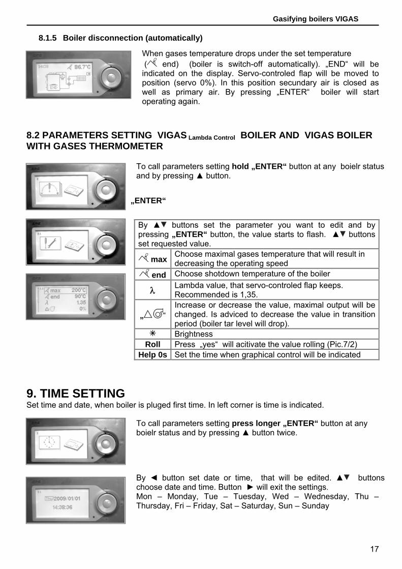
When temperature drops under the shotdown temperature (seeParameter settings of Vigas boiler in basic configuration) boiler isswitch-off automatically. „END“ will be indicated on the display. Bypressing „ENTER“ boiler will start operating again.
To call temperature setting hold „ENTER“ button at any boiler status. Symbol of the temperature setting will be indicated on thedisplay. Press „ENTER“ again. Symbol of the nominal output will be indicated on the display with value, together with temperature of outlet water in °C. By pressing the „ENTER“ button, the value startto flash.
„ENTER“ Temperature is flashing, by using buttons ▲ choose requested value. Button ► will exit the temperature settings.
To call parameters setting hold „ENTER“ button at any boiler status and by pressing ▲ button. Press „ENTER“ again Symbol of the parameters setting will be indicated on the display. By pressingthe „ENTER“ button twice, the values you can set will be indicatedon the display.
„ENTER“ „ENTER“
11
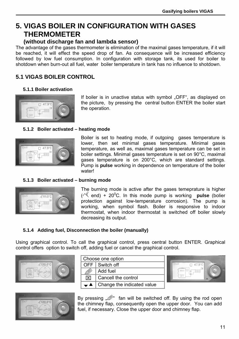
Gasifying boilers VIGAS 5. VIGAS BOILER IN CONFIGURATION WITH GASES THERMOMETER (without discharge fan and lambda sensor) The advantage of the gases thermometer is elimination of the maximal gases temperature, if it will be reached, it will effect the speed drop of fan. As consequence will be increased efficiency followed by low fuel consumption. In configuration with storage tank, its used for boiler to shotdown when burn-out all fuel, water boiler temperature in tank has no influence to shotdown. 5.1 VIGAS BOILER CONTROL
5.1.1 Boiler activation
5.1.2 Boiler activated – heating mode
5.1.3 Boiler activated – burning mode
5.1.4 Adding fuel, Disconnection the boiler (manually)
Using graphical control. To call the graphical control, press central button ENTER. Graphical control offers option to switch off, adding fuel or cancel the graphical control.
Boiler is set to heating mode, if outgoing gases temperature islower, then set minimal gases temperature. Minimal gases temperature, as well as, maximal gases temperature can be set inboiler settings. Minimal gases temperature is set on 90°C, maximal gases temperature is on 200°C, which are standard settings.Pump is pulse working in dependence on temperature of the boilerwater!
If boiler is in unactive status with symbol „OFF“, as displayed onthe picture, by pressing the central button ENTER the boiler start the operation.
The burning mode is active after the gases temeprature is higher( end) + 200C. In this mode pump is working pulse (bolier protection against low-temperature corrosion). The pump is working, when symbol flash. Boiler is responsive to indoorthermostat, when indoor thermostat is switched off boiler slowlydecreasing its output.
Choose one option OFF Switch off
Add fuel ⌧ Cancell the control
Change the indicated value
By pressing „ “ fan will be switched off. By using the rod openthe chimney flap, consequently open the upper door. You can addfuel, if necessary. Close the upper door and chimney flap.

12
Gasifying boilers VIGAS
Choose one option +60 Discharge fan active for 60s. (Using when heating) ON Boiler activation ⌧ Cancell the control
Change the indicated value
If „+60“ is chosen, new graphical control is indicated. In left corner is running time of discharge fan.
+60 Another 60s. could be added. 300s. maximum ON Boiler activation 0 Discharge fan disconnection
Change the indicated value
5.1.5 Disconnection the boiler (Automatically)
6. VIGAS BOILER IN CONFIGURATION WITH GASES THERMOMETER AND DISCHARGE FAN (without lambda sensor)
Advantages of gases thermometer are described in Chapt.5. Main advangate of discharge fan is increased comfort during heating or adding fuel. When discharge fan is active during adding fuel there is significant decrease of smudging into boiler-room. During the heating, discharge fan will accelerate the burning. 6.1 VIGAS BOILER CONTROL
6.1.1 Boiler activation
When gases temperature drops under the set temperature ( end) boiler is switch-off automatically. „END“ will be indicated on the display. By pressing „ENTER“ boiler will start operatingagain.
If boiler is in unactive status with symbol „OFF“, as displayed on the picture, by pressing the central button ENTER the boiler startthe operation.
By pressing „ “ adding fuel will be stopped. Fan will be switched on automatically.

13
Gasifying boilers VIGAS
6.1.2 Boiler activated – heating mode
6.1.3 Boiler activated – burning mode
6.1.4 Adding fuel, Disconnection the boiler (manually)
5.1.6 Disconnection the boiler (Automatically)
Boiler is set to heating mode, if outgoing gases temperature islower, then set minimal gases temperature ( end). Minimal gases temperature, as well as, maximal gases temperature can be set inboiler settings. Minimal gases temperature is set on 90°C, maximalgases temperature is set on 200°C, which are standard settings.Pump is pulse working in dependence on temperature of the boiler water!
The burning mode is active after the gases temeprature is higher( end) + 200C. In this mode pump is working pulse (bolier protection against low-temperature corrosion). The pump is working, when symbol flash. Boiler is responsive to indoor thermostat, when indoor thermostat is switched off boiler slowlydecreasing its output.
Choose one option OFF Switch off
Add fuel ⌧ Cancell the control
Change the indicated value
By pressing „ “ fan is swithed off and discharge fan is automatically activaed on 300s. In left corner is running time ofdischarge fan. If „+60“ is chosen, new graphical control is indicated. By using the rod open the chimney flap, consequently open theupper door. You can add fuel, if necessary. Close the upper door and chimney flap. By pressing „0“ discharge fan is swithed off. By pressing adding fuel is finished, discharge fan is switched off automatically and fan will switched on.
When gases temperature drops under the set temperature ( end) (boiler is switch-off automatically). „END“ will be indicated on the display. By pressing „ENTER“ boiler will startoperating again.
Using graphical control. To call the graphical control, press central button ENTER. Graphicalcontrol offers option to switch off, adding fuel or cancel the graphical control.

14
Gasifying boilers VIGAS
7. VIGAS BOILER IN CONFIGURATION WITH Lambda Control (without discharge fan)
Advantages of gases thermometer are described above. VIGAS Lambda Control boiler is delivered with built-in gases thermometer. VIGAS Lambda Control boiler utilizes informations from lambda sensor of oxygen overflow in gases, to control the flap of primary and secundary air. This system allows to burn all kinds of wood more efficiently and at the same time decreaseing the fuel consumption by 20-25%. 7.1 VIGAS Lambda Control BOILER CONTROL
7.1.1 Boiler activation
7.1.2 Boiler activated – heating mode
7.1.3 Boiler activated – burning mode
7.1.4 Adding fuel, Disconnection the boiler (manually) Using graphical control. To call the graphical control, press central button ENTER. Graphical control offers option to switch off, adding fuel or cancel the graphical control.
If boiler is in unactive status with symbol „OFF“, as displayed onthe picture, by pressing the central button ENTER the boiler start the operation.
The burning mode is active after the gases temeprature is higher( end) + 200C. Servo-controled flap wokrs in this mode as in heating mode. In this mode pump is working pulse (bolier protection against low-temperature corrosion). The pump is working, when symbol flash.
Servo-controled flap will move to open position (servo 100%)when „ENTER“ button is pressed. Consequently, futher steps(from 100% up to 45%) is moved that, value of lambda sensor is kept close to set value (λ 1,35). In position (servo 45%) secundary air is closed, in position (servo 0%) also primary air isclosed. To position 0% will be moved only if the boiler is „OFF“ or„END“. Boiler is set to heating mode, if outgoing gases temperature is lower, then set minimal gases temperature (end). Minimal gases temperature, as well as, maximal gasestemperature can be set in boiler settings. Minimal gasestemperature is set on 90°C, maximal gases temperature is set on 200°C, which are standard settings. Pump is pulse working in dependence on temperature of the boiler water!
Choose one option OFF Switch off
Add fuel ⌧ Cancell the control
Change the indicated value

15
Gasifying boilers VIGAS
Choose one option +60 Discharge fan active for 60s. (Using when heating) ON Boiler activation ⌧ Cancel the control
Change the indicated value
If „+60“ is chosen, new graphical control is indicated. In left corner is running time of discharge fan.
+60 Another 60s. could be added. 300s. maximum ON Boiler activation 0 Discharge fan disconnection
Change the indicated value
7.1.5 Boiler disconnection (automatically) 8. VIGAS Lambda Control BOILER IN CONFIGURATION WITH GASES THERMOMETER AND DISCHARGE FAN Advantages of gases thermometer and discharge fan are described above. VIGAS Lambda Control boiler utilizes informations from lambda sensor of oxygen overflow in gases, to control the flap of primary and secundary air. This system allows to burn all kinds of wood more efficiently and at the same time decreaseing the fuel consumption by 20-25%. 8.1 VIGAS Lambda Control BOILER CONTROL
8.1.1 Boiler activation
If boiler is in unactive status with symbol „OFF“, as displayed onthe picture, by pressing the central button ENTER the graphicalcontrol will be called.
By pressing „ “ fan is switched off. By using the rod open thechimney flap, consequently open the upper door. You can addfuel, if necessary. Close the upper door and chimney flap. Bypressing „ “ adding fuel will be stopped. Fan will be switched onautomatically. During fuel adding, servo-controled flap is in thesame position as before fuel adding. When adding is finished,servo-controled flap will be moved to position (servo 100%). Consequently, futher steps (from 100% up to 45%) is moved that,value of lambda sensor is kept close to set value (λ 1,35). In position (servo 45%) secundary air is closed, in position (servo0%) also primary air is closed. To position 0% will be moved onlyif the boiler is eighter „OFF“ , „END“ or switched-off fan.
When gases temperature drops under the set temperature ( end) (boiler is switch-off automatically). „END“ will be indicated on the display. Servo-controled flap will be moved to position (servo 0%). In this position secondary air is closed as well as primary air. By pressing „ENTER“ boiler will start operating again.

16
Gasifying boilers VIGAS
8.1.2 Boiler activated – heating mode
8.1.3 Boiler activated – burning mode
8.1.4 Adding fuel, boiler disconnection (manually) Using graphical control. To call the graphical control, press central button ENTER. Graphical control offers option to switch off, adding fuel or cancel the graphical control.
Servo-controled flap will moves to open position (servo 100%)when „ON“ button is pressed. Consequently, futher steps (from100% up to 45%) is moved that, value of lambda sensor is keptclose to set value (λ 1,35). In position (servo 45%) secundary air isclosed, in position (servo 0%) also primary air is closed. To position 0% will be moved only if the boiler is „OFF“ or „END“. Boiler is setto heating mode, if outgoing gases temperature is lower, then setminimal gases temperature ( end). Minimal gases temperature, as well as, maximal gases temperature can be set in boiler settings. Minimal gases temperature is set on 90°C, maximalgases temperature is set on 200°C, which are standard settings.Pump is pulse working in dependence on temperature of the boilerwater!
The burning mode is active after the gases temeprature is higher( end) + 200C. Servo-controled flap wokrs in this mode as in heating mode. In this mode pump is working pulse (bolier protection against low-temperature corrosion). The pump is working, when symbol flash.
Choose on option OFF Switch off
Add fuel ⌧ Cancell the control
Change the indicated value
By pressing „ “ fan is swithed off and discharge fan is automatically activaed on 300s. In left corner is running time ofdischarge fan. If „+60“ is chosen, new graphical control is indicated. By using the rod open the chimney flap, consequently open theupper door. You can add fuel, if necessary. Close the upper doorand chimney flap. By pressing „0“ discharge fan is swithed off. By pressing adding fuel is finished, discharge fan is switched off automatically and fan will switched on. During fuel adding, servo-controled flap is in the same position as before fuel adding. Whenadding is finished, servo-controled flap will be moved to position(servo 100%). Consequently, futher steps (from 100% up to 45%)is moved that, value of lambda sensor is kept close to set value (λ1,35). In position (servo 45%) secundary air is closed, in position(servo 0%) also primary air is closed. To position 0% will be movedonly if the boiler is eighter „OFF“ , „END“ or switched-off fan.
17
Gasifying boilers VIGAS
By ▲ buttons set the parameter you want to edit and by pressing „ENTER“ button, the value starts to flash. ▲ buttons set requested value.
max Choose maximal gases temperature that will result in decreasing the operating speed
end Choose shotdown temperature of the boiler
λ Lambda value, that servo-controled flap keeps. Recommended is 1,35.
„ “ Increase or decrease the value, maximal output will be changed. Is adviced to decrease the value in transition period (boiler tar level will drop).
Brightness Roll Press „yes“ will acitivate the value rolling (Pic.7/2)
Help 0s Set the time when graphical control will be indicated
8.1.5 Boiler disconnection (automatically)
8.2 PARAMETERS SETTING VIGAS Lambda Control BOILER AND VIGAS BOILER WITH GASES THERMOMETER
9. TIME SETTING Set time and date, when boiler is pluged first time. In left corner is time is indicated.
When gases temperature drops under the set temperature ( end) (boiler is switch-off automatically). „END“ will be indicated on the display. Servo-controled flap will be moved to position (servo 0%). In this position secundary air is closed as well as primary air. By pressing „ENTER“ boiler will start operating again.
To call parameters setting hold „ENTER“ button at any boielr status and by pressing ▲ button.
„ENTER“
To call parameters setting press longer „ENTER“ button at any boielr status and by pressing ▲ button twice.
By ◄ button set date or time, that will be edited. ▲ buttons choose date and time. Button ► will exit the settings. Mon – Monday, Tue – Tuesday, Wed – Wednesday, Thu – Thursday, Fri – Friday, Sat – Saturday, Sun – Sunday

18
Gasifying boilers VIGAS
STB
10. HARDWARE AND SOFTWARE INFORMATION 11. ERROR MESSAGES 11.1 STB failure
At „STB“ failure boiler is overheated. Thermal fuse is activated (Pic.3/21). The fan is disconnected from voltage. Boiler is activated again only if „STB“ protection is mechanical pressed. Boiler is need to be switch-on by „ENTER“ button.
12. SERVICE SETTINGS PIN 0000 PROTECTED
To call informations setting hold „ENTER“ button at any boiler status and by pressing button. ▲ buttons choose modul and confirm „ENTER“. Information about the module will be indicated on display.
To call error messages hold „ENTER“ button at any boielr status and by pressing 3 times. By pressing „ENTER“ error with description will be indicated on display.
Service settings PIN 0000 protected can be used only in restricted cases. Only trained service engineer can do these settings. (Innecessary cases client can do also). In service settings are adjusted boiler type with accessories and hydraulic connectionscheme, etc. To call the service setting PIN 0000 protected as follows: 1. Hold „ENTER“ button at any boielr status 2. Press ▲ button 3. Hold ◄ button for 4s - „PIN 0000“ will be indicated 4. Press „ENTER“ 4 times 5. Service settings symbol will be indicated on display 6. Press „ENTER“ and buttons ▲ choose service setting of
boiler type, hydraulic connection scheme, micro SD card, service operation and press „ENTER“ .
19
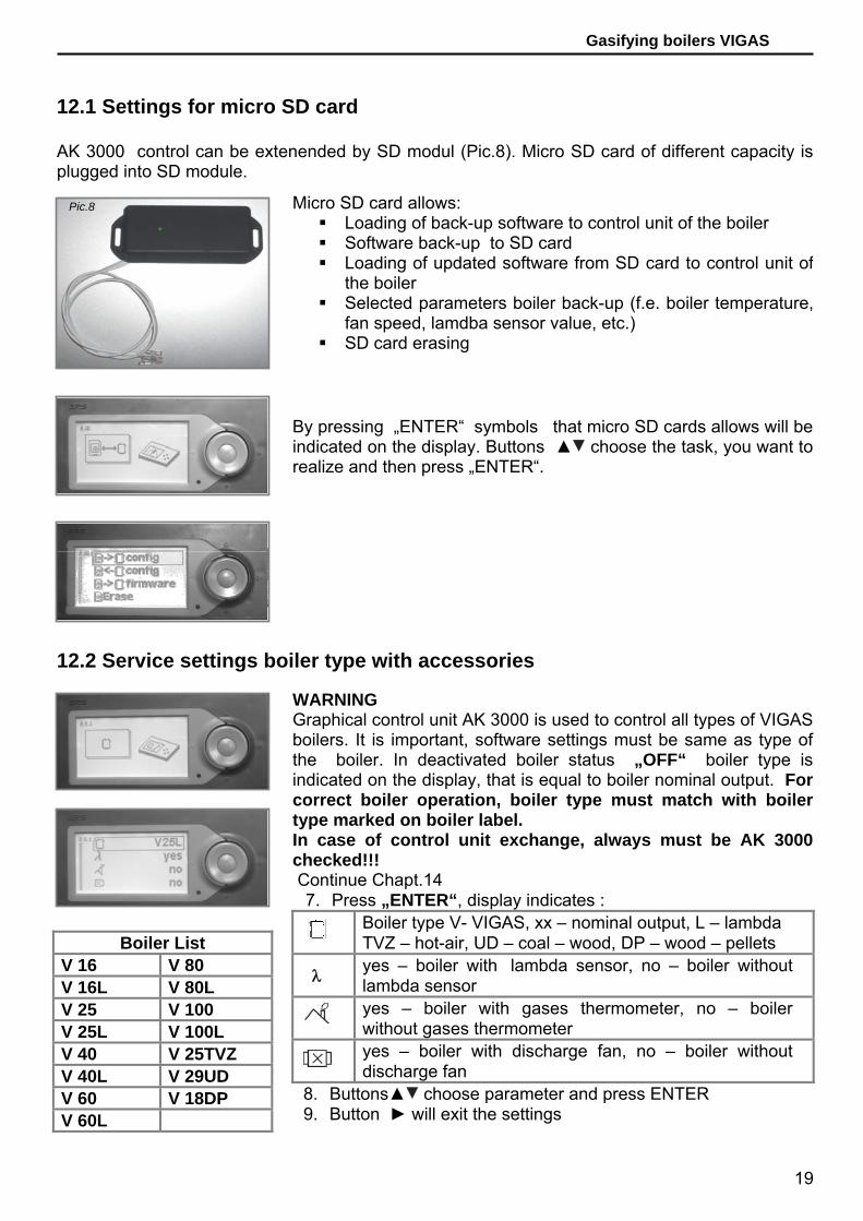
Gasifying boilers VIGAS 12.1 Settings for micro SD card AK 3000 control can be extenended by SD modul (Pic.8). Micro SD card of different capacity is plugged into SD module. 12.2 Service settings boiler type with accessories
WARNING Graphical control unit AK 3000 is used to control all types of VIGAS boilers. It is important, software settings must be same as type of the boiler. In deactivated boiler status „OFF“ boiler type is indicated on the display, that is equal to boiler nominal output. For correct boiler operation, boiler type must match with boiler type marked on boiler label. In case of control unit exchange, always must be AK 3000 checked!!! Continue Chapt.14
7. Press „ENTER“, display indicates :
Boiler type V- VIGAS, xx – nominal output, L – lambda TVZ – hot-air, UD – coal – wood, DP – wood – pellets
λ yes – boiler with lambda sensor, no – boiler without lambda sensor
yes – boiler with gases thermometer, no – boiler without gases thermometer
yes – boiler with discharge fan, no – boiler without discharge fan
8. Buttons▲ choose parameter and press ENTER 9. Button ► will exit the settings
Boiler List V 16 V 80 V 16L V 80L V 25 V 100 V 25L V 100L V 40 V 25TVZ V 40L V 29UD V 60 V 18DP V 60L
By pressing „ENTER“ symbols that micro SD cards allows will be indicated on the display. Buttons ▲ choose the task, you want to realize and then press „ENTER“.
Pic.8 Micro SD card allows: Loading of back-up software to control unit of the boiler Software back-up to SD card Loading of updated software from SD card to control unit of
the boiler Selected parameters boiler back-up (f.e. boiler temperature,
fan speed, lamdba sensor value, etc.) SD card erasing

20
Gasifying boilers VIGAS 12.3 Service settings hydraulic scheme connection
12.4 Service tools
WARNING The output contol of the pump will be changed by hydraulic connection. It is important, that software setting of hydraulic pump match the setting of the boiler in connection with central heating system. Basic memory of control contains 4 schematics. It is possible to add more schematics if necessary. Schematics that are used for additional module „EXPANDER“ are delivered on mini SD card, or will be available on www.ers.sk , free to download, through PC to memory card that will be inserted to the module of the boiler control (Chapt.13). If necessary, is it possible to return to last scheme to press „last“ Continue Chapt.14
7. Press „ENTER“, scheme 1 indicates on the display 8. Buttons ▲ choose requested scheme and press ENTER. 9. Button „ENTER“ confirm „Yes“ – to save scheme 10. To exit use ► button
Scheme 1 : Scheme is dedicated for boiler with storage tank. „LADOMAT“ provides reverse water protection. Pump is connected to boiler control and working over 40 oC. Requested temperature is possible to set up to 90 oC. T3 contact on mother board AK 3000 S is used for connection to thermometer PT 1000, which is able to measure temperature in stogare tank. Warning: It is not possible to connect indoor thermostat to T3 contact. Scheme 2 : Scheme is dedicated to central heating systems, where reverse water protection provides external control system. Pump is connected to the control and it is working pulse in dependence of boiler water temperature. T3 contact on mother board is used to connect indoor thermostat. Scheme 3 : Scheme with 3-way thermostatic valve. Pump is connected to the control and it is working pulse in dependence of boiler water temperature. T3 contact on mother board is used to connect indoor thermostat. Scheme 4 : Scheme is set as a standard. Pump is connected to the control and it is working pulse in dependence of boiler water temperature. T3 contact on mother board is used to connect indoor thermostat.
Funcionality of each system can be check in service settings by symbols indicated on display. Press „ENTER“ and selected system will be activated.
21
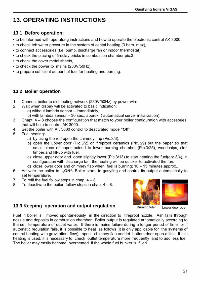
Gasifying boilers VIGAS 13. OPERATING INSTRUCTIONS 13.1 Before operation: 13.2 Boiler operation 1. Connect boiler to distributing network (230V/50Hz) by power wire. 2. Wait when dispay will be activated to basic indication:
a) without lambda sensor – immediately, b) with lambda sensor – 30 sec., approx. ( automatical server initialization).
3. Chapt. 4 – 8 choose the configuration that match to your boiler configuration with accesories, that will help to control AK 3000.
4. Set the boiler with AK 3000 control to deactvated mode "Off". 5. Fuel heating:
a) by using the rod open the chimney flap (Pic.3/3), b) open the upper door (Pic.3/2) on fireproof ceramics (Pic.3/9) put the paper so that
small piece of paper extend to lower burning chamber (Pic.3/25), woodchips, cleft timber,and fill-up with fuel,
c) close upper door and open slightly lower (Pic.3/13) to start heating the fuel(obr.3/4), in configuration with discharge fan, the heating will be quicker to activated the fan.
d) close lower door and chimney flap when fuel is burning; 10 – 15 minutes,approx., 6. Activate the boiler to „ON“. Boiler starts to gasyfing and control its output automatically to
set temperature. 7. To refil the fuel follow steps in chap. 4 – 8. 8. To deactivate the boiler, follow steps in chap. 4 – 8. 13.3 Keeping operation and output regulation Fuel in boiler is moved spontaneously in the direction to fireproof nozzle. Ash falls through nozzle and deposits in combustion chamber. Boiler output is regulated automatically according to the set temperature of outlet water. If there is mains failure during a longer period of time or if automatic regulation fails, it is possible to heat as follows (it is only applicable for the systems of central heating with gravitation flow): open chimney flap and let bottom door open a little. If this heating is used, it is necessary to check outlet temperature more frequently and to add less fuel. The boiler may easily become overheated if the whole fuel bunker is filled.
▪ to be informed with operatong instructions and how to operate the electronic control AK 3000, ▪ to check teh water pressure in the system of cental heating (3 bars. max), ▪ to connect accessories (f.e. pump, discharge fan or indoor thermostat), ▪ to check the placing of fireclay bricks in combustion chamber pic.3, ▪ to check the cover metal sheets, ▪ to check the power to mains (230V/50Hz), ▪ to prepare sufficient amount of fuel for heating and burning.
Burning fuler Lower door open

22
Gasifying boilers VIGAS 13.4 Refilling the fuel bunker with fuel ▪ open chimney flap with the help of operating rod (Pic.3/3), ▪ on graphical control press ( Available in Chapt. 4 – 8) ▪ open upper door with caution, to smoke venting ▪ refill necessary volume of fuel through upper door (Pic.3/2) ▪ close upper door (Pic.3/2) and chimney flap (Pic.3/3), ▪ button will exit refuel Important !!! ▪ Use correct fuel only ▪ Is adviced to not overload with fuel when operating the boiler in transition peridod, boiler tar level will drop. ▪ When adding fuel, do not let it remain between flange and chimney flap, which might prevent flap to close properly. ▪ Lay fuel to boiler not to prevent upper door to close. Forcible closing may damage lining. ▪ We recommend to supervise boiler according to operation conditions by the person older than 18 years. 13.5 Boiler cleaning If wood burning is optimal and minimum temperature of return water is kept, 60°C, gasification chamber, completing combustion space and exchanger are sooted minimally. If wet fuel is used, steam is condensed on the walls of combustion chamber and tar is created on surface. ▪ Gasification chamber cleaning It is necessary to remove tar from gasification chamber once per week. We recommend to burn it with upper door and chimney flap open. With regard to the fact that inner walls of boiler have aluminium coating, we do not recommend to scrape tar off mechanically ( it is only applicable for VIGAS 16, 25,40,UD29). Excessive quantity of ash, that did not fall through nozzle (9) picture 3 into fireclay combustion
Primary air hole
Pic. VIGAS 60,80,100

23
Gasifying boilers VIGAS chamber, must be removed from time to time. Thus you will increase the space of fuel bunker to original size and you will release the flow of primary air into gasification chamber. Check the continuity of openings for the intake of primary air on regular basis. If the openings are clogged, release them.
Combustion chamber cleaning
Sweep ash and dust that fell to combustion chamber with a scraper. It is sufficient to sweep ash dust that settles in combustion chamber once per 3-5 days.
Exchanger cleaning It is necessary to clean exchanger pipes once per month with a “cleaning plate”. Put cap away, (15) picture 3, and thus you will have an access to exchanger pipes. Recommendation: If you do not clean the exchanger on time and it is too dirty, do not use any dissolvent for tar. Boiler must be clean while it is hot. Heat boiler through open chimney flap and upper door approx. at 800C ( without fan). Then close flap and door. Carefully (use gloves) open exchanger cap. Clean dirty exchanger with relevant accessories. After cleaning, close exchanger cap and let boiler burn / gasification/ approx 5 hours as maximum output in order the rest of tar might burn. Warning: Boiler room must be properly ventilated during burning.
Air piping cleaning The clearness of boiler piping system is a necessary condition for right burning. If you mainly use sawdust, it is necessary to clean the piping system once per heating season. After putting fan cover (8) picture 3 and sheet cover of piping away, you will get access to two pipes. Use vacuum cleaner to remove sawdust and check continuity.
Step1. Step 2. Step 3.
Secondary air Primary air
Step 1. Step 2. Step 3.
Primary air
Secondary air
24
Gasifying boilers VIGAS VIGAS UD 29 cleaning
If you use brow coal, clean boiler as stated for wood. Clean fuel bunker with a cleaning flap (12) picture 3 and ashtray drawer (31)picture 3 as follows 1. Open bottom door (15) picture 5, stuff ashtray drawer and close door 2. Open cleaning flap and upper door (2) picture 5. 3. Use relevant accessories to pile up ash from fuel bunker space to drawer 4. Wait some time, open bottom door, take drawers and close it WARNING: Do not leave ashtray drawer in boiler during operation. 14. BOILER MAINTENANCE AND REPAIRS The contractor ensures regular checks and boiler maintenance. During boiler operation, it is necessary to check water pressure, door tightness, chimney flap tightness, exchanger cap tightness, chimney tightness and fan performance. NOTE: Before boiler shutting down during summer season, clean combustion chamber properly not to leave any condensed moisture there and open bottom door and chimney flap. 14.1 Door tightness:
Boiler door are stabilized in three points, on two revolving pins and on closing. If door does not fit tightly, besides revolving closing it is also possible to fix it from hinge side. You can slightly turn hinge bolt with releasing and turning nuts and thus you turn door in a desired direction. In case of sealing rope exchange “1” is a connecting point.
14.2 Chimney flap tightness: When cleaning exchanger pipes (Pic. 3/24), check if flap closes tightly. Check chimney flap (Pic. 3/16) for the same as well. Leakage may result in decreased boiler output. 14.3 Heatproof nozzle
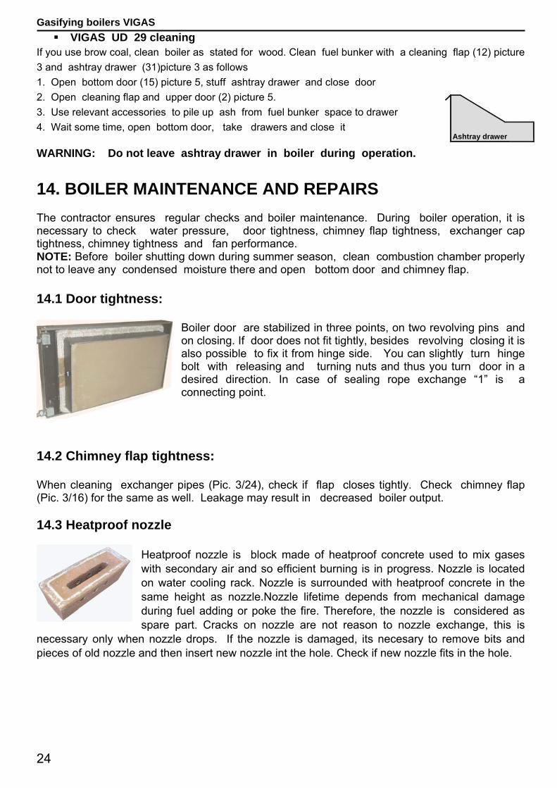
Heatproof nozzle is block made of heatproof concrete used to mix gases with secondary air and so efficient burning is in progress. Nozzle is located on water cooling rack. Nozzle is surrounded with heatproof concrete in the same height as nozzle.Nozzle lifetime depends from mechanical damage during fuel adding or poke the fire. Therefore, the nozzle is considered as spare part. Cracks on nozzle are not reason to nozzle exchange, this is
necessary only when nozzle drops. If the nozzle is damaged, its necesary to remove bits and pieces of old nozzle and then insert new nozzle int the hole. Check if new nozzle fits in the hole.
Ashtray drawer

25
Gasifying boilers VIGAS 14.4 Setting the position of servo VIGAS Lambda Control boiler Correct setting of servo and flap for secondary air control is a key factor for burning with minmum emission. Servo and flap can be set in follows:
Step1: Disconnect power wire from distributing network 230V/50Hz, Step2: Loose screw „1“ with fork wrench, Step3: Turn the shaft with screwdriver „2“ to maximal position, anti-clockwise and push softly in direction to the boiler, shaft must be rotate easily!!! Check the flap movement in hole „3“, Step4: Draw close screw „1“ Step5: Connectpower wire into distributing network
230V/50Hz. Automatical initialization, indicated on display, starts when power wire is connected into distributing network. During initialization servo will be pushed. When boiler is activated to „ON“ mode, flap will be moved to opposite position in anti-clockwise direction, where is controled eighter primary and secondary air to requested value λ. 14.5 Setting the position of secondary air flaps of VIGAS boiler
The quality of burning can be increased by secondary air flaps. VIGAS Lambda Control boilers regulate amount of secondary air automatically, therefore the quality of the burning is high. In VIGAS boilers withouth lambda sensor is adjusted with screws „1“. Optimal settings form production is adjusted to 2,5 turns „1“. When change or check the setting follow the steps:
Step1: „1“ loose the safety nut, Step2: Draw close screw „1“ in direction to the boiler, Step3: Loose the screw, back on 2,5 turns (optimum), Step4: Draw close the safety nut. Boiler without lambda sensor, safety flap is located above the fan „2“, that avert burning without fan (chimneay draught). If boiler has lack of output , check flap functionality „2“. 14.6 Lambda sensor and gases thermometer
Cleanness is important for correct functionality of lambda senosor and gases thermometer. Gently wipe dust from lambda sensor „1“ and gases thermometer „2“, when cleaning. Important: Gases thermometer must be in correct position. Correct position of gases thermometer „2“ – end of the metal gases thermometer must be together with end-socket. (to change the position of the gases thermometer, indicated value will be changed significantly). Disconnect („3“ and „4“) gases thermometer or lambda
sensor if changed. If boiler does not contain terminals „3“ and „4“ disconnection must be realized directly from mother board AK 3000S.
TURN FUEL 0 Not recommended 1 Wet wood
1,5 Wet softwood 2 Dry softwood
2,5 Dry hardwood 2,5 and more
Very dry, hardwood, small pieces
26
Gasifying boilers VIGAS
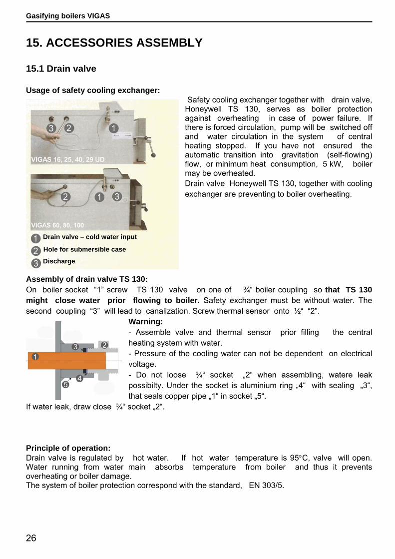
Discharge
Hole for submersible case
Drain valve – cold water input
15. ACCESSORIES ASSEMBLY 15.1 Drain valve Usage of safety cooling exchanger:
Safety cooling exchanger together with drain valve, Honeywell TS 130, serves as boiler protection against overheating in case of power failure. If there is forced circulation, pump will be switched off and water circulation in the system of central heating stopped. If you have not ensured the automatic transition into gravitation (self-flowing) flow, or minimum heat consumption, 5 kW, boiler may be overheated. Drain valve Honeywell TS 130, together with cooling exchanger are preventing to boiler overheating.
Assembly of drain valve TS 130: On boiler socket “1” screw TS 130 valve on one of ¾“ boiler coupling so that TS 130 might close water prior flowing to boiler. Safety exchanger must be without water. The second coupling “3” will lead to canalization. Screw thermal sensor onto ½“ “2”.
Warning: - Assemble valve and thermal sensor prior filling the central heating system with water. - Pressure of the cooling water can not be dependent on electrical voltage. - Do not loose ¾“ socket „2“ when assembling, watere leak possibilty. Under the socket is aluminium ring „4“ with sealing „3“, that seals copper pipe „1“ in socket „5“.
If water leak, draw close ¾“ socket „2“. Principle of operation: Drain valve is regulated by hot water. If hot water temperature is 95°C, valve will open. Water running from water main absorbs temperature from boiler and thus it prevents overheating or boiler damage. The system of boiler protection correspond with the standard, EN 303/5.
27
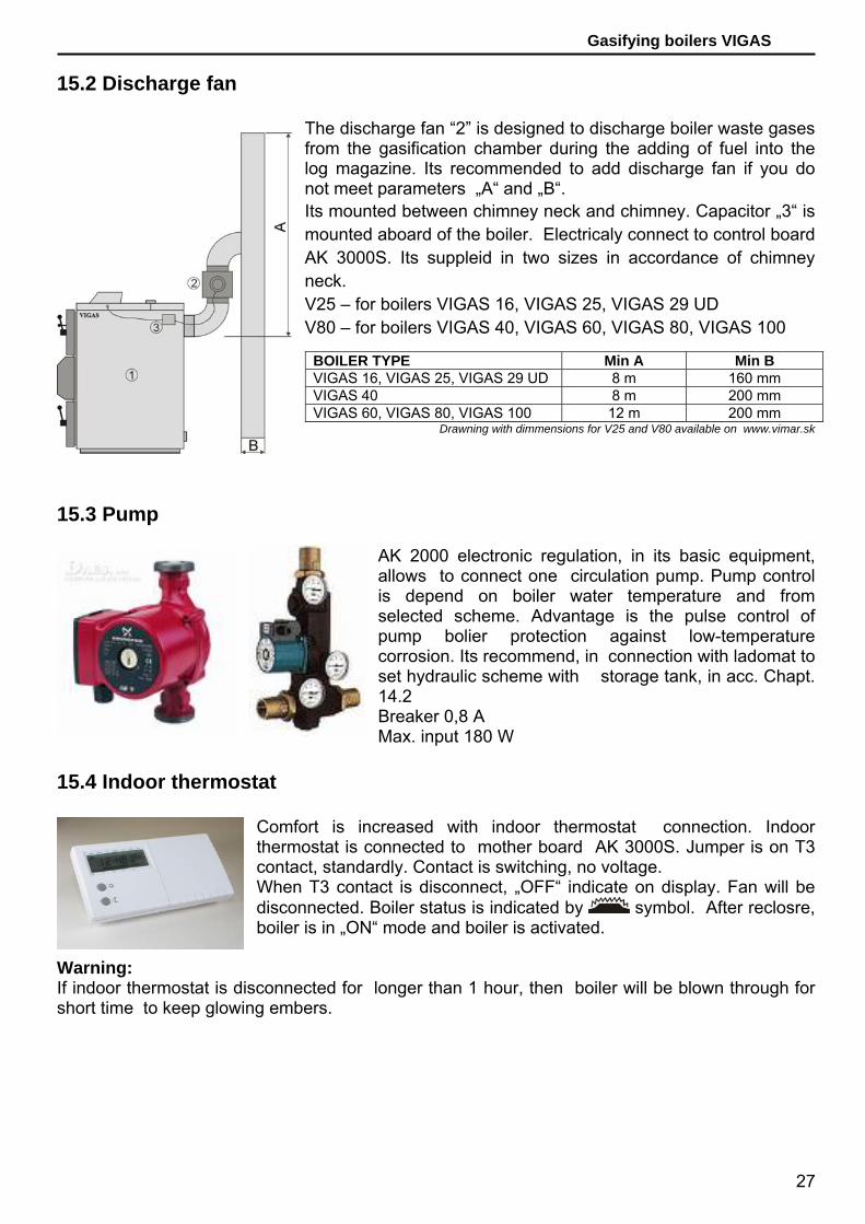
Gasifying boilers VIGAS 15.2 Discharge fan
The discharge fan “2” is designed to discharge boiler waste gases from the gasification chamber during the adding of fuel into the log magazine. Its recommended to add discharge fan if you do not meet parameters „A“ and „B“. Its mounted between chimney neck and chimney. Capacitor „3“ is mounted aboard of the boiler. Electricaly connect to control board AK 3000S. Its suppleid in two sizes in accordance of chimney neck. V25 – for boilers VIGAS 16, VIGAS 25, VIGAS 29 UD V80 – for boilers VIGAS 40, VIGAS 60, VIGAS 80, VIGAS 100
15.3 Pump
AK 2000 electronic regulation, in its basic equipment, allows to connect one circulation pump. Pump control is depend on boiler water temperature and from selected scheme. Advantage is the pulse control of pump bolier protection against low-temperature corrosion. Its recommend, in connection with ladomat to set hydraulic scheme with storage tank, in acc. Chapt. 14.2 Breaker 0,8 A Max. input 180 W
15.4 Indoor thermostat
Comfort is increased with indoor thermostat connection. Indoor thermostat is connected to mother board AK 3000S. Jumper is on T3 contact, standardly. Contact is switching, no voltage. When T3 contact is disconnect, „OFF“ indicate on display. Fan will be disconnected. Boiler status is indicated by symbol. After reclosre, boiler is in „ON“ mode and boiler is activated.
Warning: If indoor thermostat is disconnected for longer than 1 hour, then boiler will be blown through for short time to keep glowing embers.
BOILER TYPE Min A Min B VIGAS 16, VIGAS 25, VIGAS 29 UD 8 m 160 mm VIGAS 40 8 m 200 mm VIGAS 60, VIGAS 80, VIGAS 100 12 m 200 mm
Drawning with dimmensions for V25 and V80 available on www.vimar.sk
28
Gasifying boilers VIGAS
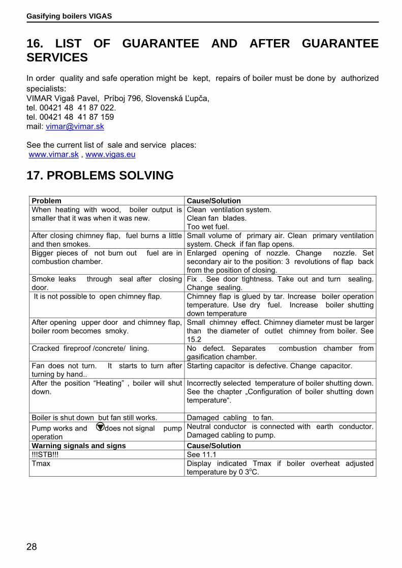
16. LIST OF GUARANTEE AND AFTER GUARANTEE SERVICES In order quality and safe operation might be kept, repairs of boiler must be done by authorized specialists: VIMAR Vigaš Pavel, Príboj 796, Slovenská Ľupča, tel. 00421 48 41 87 022. tel. 00421 48 41 87 159 mail: [email protected] See the current list of sale and service places: www.vimar.sk , www.vigas.eu 17. PROBLEMS SOLVING
Problem Cause/Solution When heating with wood, boiler output is smaller that it was when it was new.
Clean ventilation system. Clean fan blades. Too wet fuel.
After closing chimney flap, fuel burns a little and then smokes.
Small volume of primary air. Clean primary ventilation system. Check if fan flap opens.
Bigger pieces of not burn out fuel are in combustion chamber.
Enlarged opening of nozzle. Change nozzle. Set secondary air to the position: 3 revolutions of flap back from the position of closing.
Smoke leaks through seal after closing door.
Fix . See door tightness. Take out and turn sealing. Change sealing.
It is not possible to open chimney flap. Chimney flap is glued by tar. Increase boiler operation temperature. Use dry fuel. Increase boiler shutting down temperature
After opening upper door and chimney flap, boiler room becomes smoky.
Small chimney effect. Chimney diameter must be larger than the diameter of outlet chimney from boiler. See 15.2
Cracked fireproof /concrete/ lining. No defect. Separates combustion chamber from gasification chamber.
Fan does not turn. It starts to turn after turning by hand..
Starting capacitor is defective. Change capacitor.
After the position “Heating” , boiler will shut down.
Incorrectly selected temperature of boiler shutting down. See the chapter „Configuration of boiler shutting down temperature“.
Boiler is shut down but fan still works. Damaged cabling to fan. Pump works and does not signal pump operation
Neutral conductor is connected with earth conductor. Damaged cabling to pump.
Warning signals and signs Cause/Solution !!!STB!!! See 11.1 Tmax Display indicated Tmax if boiler overheat adjusted
temperature by 0 3oC.

29
Gasifying boilers VIGAS 18. ASSEMBLY INSTRUCTION
For connection, as shown on picture 9, boiler is delivered standardly. In cease of need is possible to mount pump to boiler circuit. In such case, both boilers are connected together in terminal on AK 3000S. Sum of input power both pumps can not be higher than 150W.
For connection, as shown on picture 10, its recommend to set graphical scheme on display in accordance chapt. 12.3. See other schemes of connection and other possible regulations www.vimar.sk.
18.1 Assembly and maintainance instructions
Boiler can only be connected to the system of central heating whose thermal capacity correspond with boiler output.
When forced circulation used and there is mains failure (boiler and pump stop to operate), the system of central heating must be adapted to ensure minimum boiler power take-off, 5 kW. This is provided with safety cooling exchanger with drain valve, Honeywell TS 130( Honeywell is not a component part of delivery, it should be ordered separetly).
Boiler must be connected correctly and as short as possible to chimney. Other appliances must not be connected to chimney. Chimney shaft must be dimensioned according to the standards: STN 734201 and STN 734210.
We do not recommend permanent connection to water supply through feed water valve to avoid not allowed increase in pressure if valve is not tightly sealed. Maximum overpressure is 0,3 MPa.
The room where boiler is placed must be ventilated properly.
Recommended schema of basic connection with AK 3000 regulation.
1. VIGAS boiler 2. Safety valve 3. Indoor thermostat 4. Circulation Pump 5. Hot water storage tank 6. Four-way blender 7. Central heating circuit 8. Exp. bin 9. Storage tank 10. Gases thermometer R- Distributer Z- Collector Pic.10
Pic.9

30
Gasifying boilers VIGAS Boiler assembly must be done by specialists of assembly firms. Boiler need not be placed on a firm base. Minimum temperature of reversible water at boiler inlet is 60 0C. Boiler room must be ventilated permanently through the opening of min. diameter 0,025
m2. The diameter for air inlet and outlet must equal approximately. Boiler must be installed in the surrounding that is common, basic in accordance with the
standard, STN 33 2000-3. Work and health safety regulations must be followed in accordance with current
instruction requirements, UBP SR No. 718/2002 Coll. and seq. Z hľadiska požiarno-technické vlastnosti hmôt v blízkosti kotla musia byť splnené
požiadavky normy STN 73 0823:1983/z1 - Stupeň horľavosti stavebných hmôt. 18.2 Safety regulations for control and maintenance of VIGAS boiler electric equipment The boiler operator must follow relevant regulations and standards, as well as the following principles: If boiler is in operation, none of the following may be done with electric equipment:
o uncover electronic equipment, e.g. boiler electronics, fan, thermostat, o to exchange fuse, o to repair damaged cable insulation etc.
Maintenance and repairs of boiler with uncovered electric equipment may only be done by persons authorized to do so according to 74/1996 Coll.
Before uncovering boiler or any electric equipment connected to boiler, it is necessary to disconnect any mains /unplug/. You can only plug in after placing covers on original places.
If there is any defect of electric equipment or boiler installation is damaged it is important: - do not touch any part of boiler
o disconnect boiler from mains /unplug/. o to call an authorized service technician that will correct defect.
Apart from common maintenance of boiler, it is strictly forbidden: to manipulate electric equipment and boiler installation if plugged in, to touch damaged electric equipment and boiler installation, mainly damage cable insulation ,
etc., o to operate boiler if uncovered,, o to operate boiler with defective electric equipment or defective boiler installation, o to repair damaged boiler electric parts by persons unauthorized by the producer
31
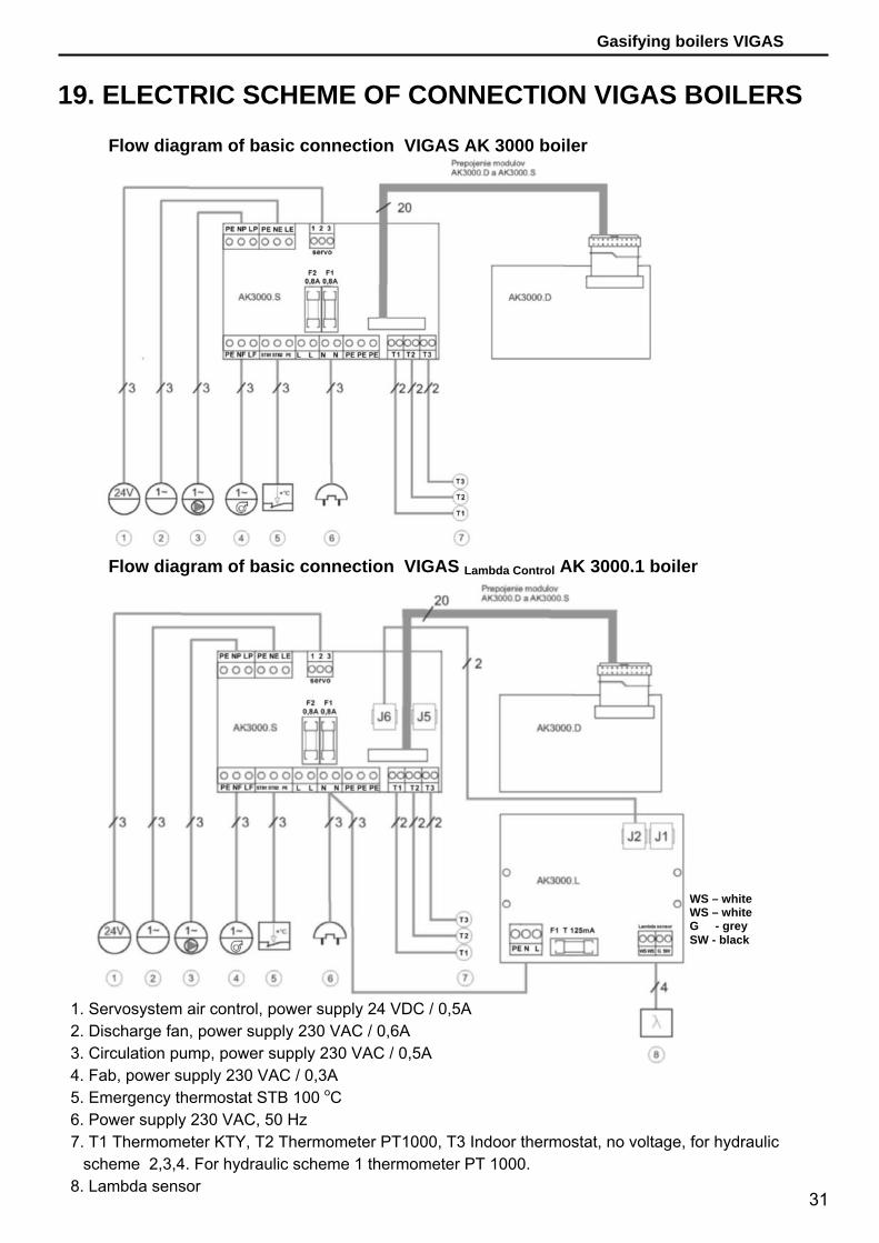
Gasifying boilers VIGAS 19. ELECTRIC SCHEME OF CONNECTION VIGAS BOILERS
Flow diagram of basic connection VIGAS AK 3000 boiler
Flow diagram of basic connection VIGAS Lambda Control AK 3000.1 boiler
1. Servosystem air control, power supply 24 VDC / 0,5A 2. Discharge fan, power supply 230 VAC / 0,6A 3. Circulation pump, power supply 230 VAC / 0,5A 4. Fab, power supply 230 VAC / 0,3A 5. Emergency thermostat STB 100 oC 6. Power supply 230 VAC, 50 Hz 7. T1 Thermometer KTY, T2 Thermometer PT1000, T3 Indoor thermostat, no voltage, for hydraulic
scheme 2,3,4. For hydraulic scheme 1 thermometer PT 1000. 8. Lambda sensor
WS – white WS – white G - grey SW - black
32
Gasifying boilers VIGAS
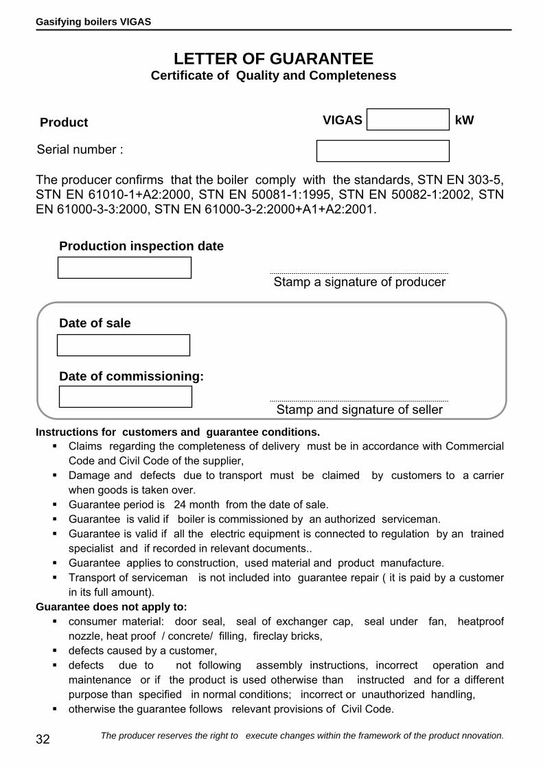
LETTER OF GUARANTEE
Certificate of Quality and Completeness
Product
Serial number :
The producer confirms that the boiler comply with the standards, STN EN 303-5, STN EN 61010-1+A2:2000, STN EN 50081-1:1995, STN EN 50082-1:2002, STN EN 61000-3-3:2000, STN EN 61000-3-2:2000+A1+A2:2001.
Production inspection date
Date of sale
Date of commissioning:
Stamp and signature of seller
Instructions for customers and guarantee conditions. Claims regarding the completeness of delivery must be in accordance with Commercial
Code and Civil Code of the supplier, Damage and defects due to transport must be claimed by customers to a carrier
when goods is taken over. Guarantee period is 24 month from the date of sale. Guarantee is valid if boiler is commissioned by an authorized serviceman. Guarantee is valid if all the electric equipment is connected to regulation by an trained
specialist and if recorded in relevant documents.. Guarantee applies to construction, used material and product manufacture. Transport of serviceman is not included into guarantee repair ( it is paid by a customer
in its full amount). Guarantee does not apply to:
consumer material: door seal, seal of exchanger cap, seal under fan, heatproof nozzle, heat proof / concrete/ filling, fireclay bricks,
defects caused by a customer, defects due to not following assembly instructions, incorrect operation and
maintenance or if the product is used otherwise than instructed and for a different purpose than specified in normal conditions; incorrect or unauthorized handling,
otherwise the guarantee follows relevant provisions of Civil Code.
The producer reserves the right to execute changes within the framework of the product nnovation.
Stamp a signature of producer
VIGAS kW
33
Gasifying boilers VIGAS
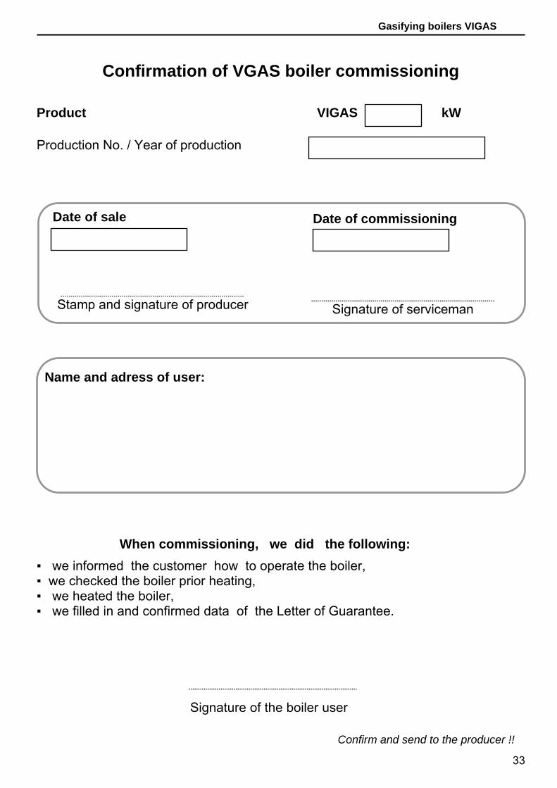
Confirmation of VGAS boiler commissioning
Product VIGAS kW
Production No. / Year of production
Name and adress of user:
When commissioning, we did the following: ▪ we informed the customer how to operate the boiler, ▪ we checked the boiler prior heating, ▪ we heated the boiler, ▪ we filled in and confirmed data of the Letter of Guarantee.
Signature of the boiler user
Confirm and send to the producer !!
Date of sale Date of commissioning
Signature of serviceman
Stamp and signature of producer

34
Gasifying boilers VIGAS
35
Gasifying boilers VIGAS
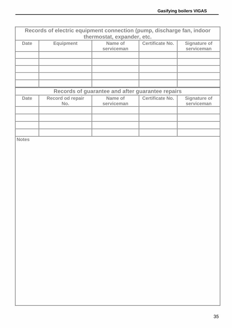
Records of electric equipment connection (pump, discharge fan, indoor thermostat, expander, etc.
Date Equipment Name of serviceman
Certificate No. Signature of serviceman
Records of guarantee and after guarantee repairs Date Record od repair
No. Name of
serviceman Certificate No. Signature of
serviceman Notes
36
Gasifying boilers VIGAS
Ecological and gasifying boiler
Producer: VIMAR Vigas Pavel
M. Culena 25 974 11 Banska Bystrica
SLOVENSKO
Production plant: VIMAR Vigas Pavel
Priboj 796 976 13 Slovenska Lupca
SLOVAKIA tel.: 00421 48 4187 022 fax: 00421 48 4187 159
WWW.VIMAR.SK [email protected]
Serial number
All technical changes are reserved for VIMAR 2009 ver.1Pictures are illustrative and might be different from the reality!