Ecodesign and labelling of Boilers
55
EN EN Ecodesign and labelling of Boilers Document 1 Introduction In reaction to the first consultation forum meeting and the documents presented there, the Commission has received comments from many stakeholders and Member States. There have also been technical and relevant legislative developments at EU level, for example the recast of the Energy Performance of Buildings Directive with its Article 8 on proper installation of products. This justifies a second meeting of the consultation forum and the submission of new working documents. The main elements in the text that you receive today: • Combi-boilers, micro-cogeneration, and cylinders are included in the scope, as well as fossil fuelled boilers, electrical central heating, heat pumps, and solar heating. • The proposed scope is up to 400 kW. • The calculation model for energy efficiency has been simplified. • Testing points have been adjusted. • Third party testing is the norm. • NOx emission values have been changed. • There is a provision for co-firing of renewable energy. • The effect of controls on energy efficiency is addressed. • Possible problems for replacing small boilers in apartment blocks have been taking into account in setting efficiency requirements (chimney issue). In addition, without specifying the layout format, some indicative ideas for labelling are included, to get a preliminary opinion from Member States and stakeholders pending discussions with the European Parliament and Council on the way forward regarding the label.
Transcript of Ecodesign and labelling of Boilers

EN EN
Ecodesign and labelling of Boilers
Document 1 Introduction
In reaction to the first consultation forum meeting and the documents presented there, the Commission has received comments from many stakeholders and Member States. There have also been technical and relevant legislative developments at EU level, for example the recast of the Energy Performance of Buildings Directive with its Article 8 on proper installation of products. This justifies a second meeting of the consultation forum and the submission of new working documents.
The main elements in the text that you receive today:
• Combi-boilers, micro-cogeneration, and cylinders are included in the scope, as well as fossil fuelled boilers, electrical central heating, heat pumps, and solar heating.
• The proposed scope is up to 400 kW.
• The calculation model for energy efficiency has been simplified.
• Testing points have been adjusted.
• Third party testing is the norm.
• NOx emission values have been changed.
• There is a provision for co-firing of renewable energy.
• The effect of controls on energy efficiency is addressed.
• Possible problems for replacing small boilers in apartment blocks have been taking into account in setting efficiency requirements (chimney issue).
In addition, without specifying the layout format, some indicative ideas for labelling are included, to get a preliminary opinion from Member States and stakeholders pending discussions with the European Parliament and Council on the way forward regarding the label.

EN EN
Document 2
WORKING DOCUMENT on possible ecodesign requirements
for boilers

EN 2 EN
Chapter 1 Subject matter and scope
1. This Regulation establishes ecodesign requirements for the placing on the market of gas-fired, oil-fired and electric boilers for hydronic central space heating (hereafter ‘Boilers’) up to 400 kW, Boilers with also a water heating function (‘Combi-boiler’) up to 400 kW and storage tanks used for central heating water or sanitary hot water (‘Cylinders’) in accordance with the definitions in Document 3. This includes Boilers also using solar energy and/or ambient heat, as well as Boilers that produce electricity as a by-product of the heat generation.
2. This Regulation shall not apply to the following products:
(a) space- and/or water heating devices within the scope of Directive 2001/80/EC on Large Combustion Plants (LCPD);
(b) space- and/or water heating devices using solid fuels, including biomass, as an energy source;
(c) space- and/or water heating devices included in and/or linked with District Heating systems (“DH”), such as large dedicated DH boilers and systems fuelled by waste heat from central power plants, waste incineration plants, larger industrial installations etcetera;
(d) centralised and local space heating devices based on air heating (e.g. reversible room- or centralized air conditioners);
(e) components placed on the market also as separate products that are not capable of performing the primary functions defined in Chapter 2. This includes but is not limited to burners, heat exchangers and controls;
(f) Boilers with a maximum heat output below 3.5 kW. Combi-boilers not capable of fulfilling the requirements of the smallest tapping pattern XXS as defined in Commission Regulation XX/XX/EC but with a maximum heat input above or equal to 3,5 kW shall not be evaluated on their water heating function but will be treated as boilers for space heating;
(g) Boilers and Combi-boilers designed for the use of biogas and/or -oil, or mixtures of fossil and bio gas/oil with a bio fuel content of 10% or more.
(h) Heating devices with only one CH-emitter and/or where the product itself predominantly works as the heat emitter for space heating (local heaters);
(i) Boilers or furnaces using vapor (steam heating systems), air (air heating systems) or other gaseous heat transfer media (e.g. some reversible air conditioner systems), boilers or furnaces supplying a heat transfer liquid with operational temperatures higher than 100 °C;
(j) Boilers that, either through their physical characteristics and/or through the manufacturer’s instructions, are designated to function only with CH-emitters that wholly depend on mechanically induced forced air convection for their functionality (e.g. indirect air heating systems).
(k) Dedicated water heaters as defined in Commission Regulation XX/XX/EC.
EN 3 EN
Chapter 2 Definitions
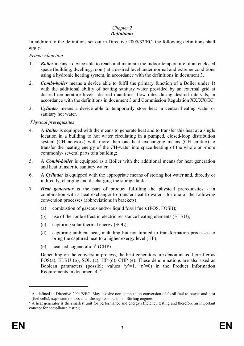
In addition to the definitions set out in Directive 2005/32/EC, the following definitions shall apply:
Primary function
1. Boiler means a device able to reach and maintain the indoor temperature of an enclosed space (building, dwelling, room) at a desired level under normal and extreme conditions using a hydronic heating system, in accordance with the definitions in document 3.
2. Combi-boiler means a device able to fulfil the primary function of a Boiler under 1) with the additional ability of heating sanitary water provided by an external grid at desired temperature levels, desired quantities, flow rates during desired intervals, in accordance with the definitions in document 3 and Commission Regulation XX/XX/EC.
3. Cylinder means a device able to temporarily store heat in central heating water or sanitary hot water.
Physical prerequisites
4. A Boiler is equipped with the means to generate heat and to transfer this heat at a single location in a building to hot water circulating in a pumped, closed-loop distribution system (CH network) with more than one heat exchanging means (CH emitter) to transfer the heating energy of the CH-water into space heating of the whole or -more commonly- several parts of a building;
5. A Combi-boiler is equipped as a Boiler with the additional means for heat generation and heat transfer to sanitary water.
6. A Cylinder is equipped with the appropriate means of storing hot water and, directly or indirectly, charging and discharging the storage tank.
7. Heat generator is the part of product fulfilling the physical prerequisites - in combination with a heat exchanger to transfer heat to water - for one of the following conversion processes (abbreviations in brackets):
(a) combustion of gaseous and/or liquid fossil fuels (FOS, FOSB);
(b) use of the Joule effect in electric resistance heating elements (ELBU);
(c) capturing solar thermal energy (SOL);
(d) capturing ambient heat, including but not limited to transformation processes to bring the captured heat to a higher exergy level (HP);
(e) heat-led cogeneration1. (CHP)
Depending on the conversion process, the heat generators are denominated hereafter as FOS(a), ELBU (b), SOL (c), HP (d), CHP (e). These denominations are also used as Boolean parameters (possible values ‘y’=1, ‘n’=0) in the Product Information Requirements in document 4. 2
1 As defined in Directive 2004/8/EC. May involve non-combustion conversion of fossil fuel to power and hest
(fuel cells), explosion motors and –through combustion—Stirling engines 2 A heat generator is the smallest unit for performance and energy efficiency testing and therefore an important concept for compliance testing.

EN 4 EN
8. Preferential heat generators in a multiple heat generator product indicate those heat generators used to the maximum of their capacity, within the restriction of the given heat demand. By definition SOL, HP and FOS are preferential and shall be used - in that order - to fill in the heat demand to the maximum of their capacity. In a multiple heat generator product, ELBU3 and FOSB are non-preferential, i.e. by definition they fill in the remaining heat demand.
9. Efficiency of Boilers and Combi-boilers is the ratio between theoretical minimum heating energy demand and actual primary energy consumption expressed in gross calorific value of the fossil fuel and the primary energy equivalent of the net electricity consumed or produced in meeting aforementioned heating energy demand.
10. Specific efficiency of Boilers and Combi-boilers is the energy efficiency performance defined for a designated load profile and designated climate under normal reference conditions.
11. Load profile is a set of heating energy demand (‘load’) parameters representing the seasonal space heating or annual water heating load, based on aggregated building and installation characteristics as well as the designated climate. Depending on the size of the space or water heating demand, load profiles are denominated - from low to high - as ‘XXS’ (for water heating only), ‘XS’, ‘S’, ‘M’, ‘L’, ‘XL’, ‘XXL’, ‘3XL’ and ‘4XL’.
12. Climate in this regulation is a set of representative meteorological data (e.g. outdoor temperature, solar irradiance) for representative locations in the European Union and determining –within a given physical context—the load profile and the potential for the usage of solar energy and ambient heat. For the purpose of this regulation an Average (‘A’), Warmer (‘W’) and Colder (‘C’) climate are given, based on 1982-1999 weather data of Strasbourg (France), Athens (Greece) and Helsinki (Finland) respectively.
13. Normal reference conditions relate to the heat demand parameters for the average meteorological conditions, as opposed to extreme reference conditions, which relate to the peak load (maximum) demand.
14. Designated load profile(s) or climate(s) are (is) the load profile(s) or climate(s) for which the manufacturer declares the product fit for purpose and able to meet the Minimum Performance requirements as part of the Product Information Requirements in document 4, whereby the option to choose other climates than the Average is only relevant for products containing SOL or HP heat generator types.
15. ‘Fit-for-purpose’ in this regulation is a concept exclusively depending on the manufacturer’s declaration.
16. Minimum Performance requirements in document 4 are conditions verifying the capacity of the product to meet the heating energy demand under extreme reference conditions pertaining to the designated load profiles and - if appropriate - climate(s), in accordance with 32/2005/EC, Art. 15, sub x stipulating that ecodesign requirements shall not negatively impact the functionality of the product.
17. Minimum Performance requirement for space heating is the capacity of the Boiler to meet the (peak) heating power demand Pdesign in kW of the highest designated space heating load profile at design outdoor temperatures of –10 °C (Average climate), +2 °C (Warmer) and –22 °C (Colder), as specified in document 4.
3 Note that this does not exclude that in a single heat generator configuration ELBU can function as the only
heat generator .(e.g. electric resistance boiler).

EN 5 EN
18. Minimum Performance requirement for water heating is the capacity of the Combi-boiler to meet the requirements of the tapping profile pertaining to the highest designated water heating load profile as specified in Commission Regulation XX/XX/EC and characterised by a 24h sequence of draw-off with per draw-off a specified (a) start time, in time h [hh:mm] elapsed from the start of the tapping pattern;
(b) useful energy content of hot water to be achieved in kWh;
(c) minimum flow rate in l/min;
(d) useful temperature of hot water from which counting of useful energy content starts in ºC;
(e) minimum (peak) temperature to be achieved during tapping in ºC.
19. Specific efficiency for space heating (etas) of a Boiler is the calculated energy efficiency values for a load profile and climate as defined in document 7, based on test results as given in document 6 and technical definitions in accordance with document 3. In case of SOL and air-source HP the specific efficiency for a load profile is denominated etasA (average climate), etasW (Warmer climate) and etasC (Colder climate), depending on the climate.
20. Specific efficiency for water heating (etawh) of a Combi-boiler is the calculated energy efficiency performance, derived from tapping pattern measurements, as defined in Commission Regulation XX/XX/EC and subsequently corrected for combi-specific factors as specified in document 3 (Technical Definitions) and document 6 (Testing). In case of SOL and air-source HP the specific efficiency for a load profile is denominated etawhA (average climate), etawhW (Warmer climate) and etawhC (Colder climate), depending on the climate.
21. Energy index Cylinders is the volume-specific (in ltrs) energy loss (in W) of the storage tank measured at an average water temperature of 60 ºC and an ambient temperature of 20 ºC as defined in document 4.
Additional technical definitions are set out in document 3.
Chapter 3 Ecodesign requirements
The ecodesign requirements for the covered products are set out in document 4.
Chapter 4 Conformity assessment
1. The procedure for assessing conformity referred to in Article 8(2) of Directive 2005/32/EC shall be Module B as set out in Decision No 768/2008/EC as defined in Annex IV, Table 2 of said Decision.
2. For the purposes of conformity assessment pursuant to Article 8 of Directive 2005/32/EC, the technical documentation file shall include the results of the calculations required in documents 5 and 6.

EN 6 EN
Chapter 5 Verification procedure for market surveillance purposes
When performing the market surveillance checks referred to in Article 3(2) of Directive 2005/32/EC for the requirements set out in document 4, the Member State authorities shall apply the verification procedure set out in document 7.
Chapter 6 Benchmarks
The indicative benchmarks for Boilers at the time of entry into force of this Regulation are set out in document 8.
Chapter 7 Revision
The Commission shall review this Regulation in the light of technological progress no later than five years after its entry into force and present the result of this review to the Ecodesign Consultation Forum.
Chapter 8 Repeal
Directive 1992/42/EC is repealed from the date of application of the first ecodesign requirements.
Chapter 9 Entry into force
1. This Regulation shall enter into force on the twentieth day following that of its publication in the Official Journal of the European Union.
2. The ecodesign requirements set out in points 1(1) of document 4 shall apply from one year after entry into force.
3. The ecodesign requirements set out in point 1(2) of document 4 shall apply from one year after entry into force.
4. This Regulation shall be binding in its entirety and directly applicable in all Member States.
EN 7 EN
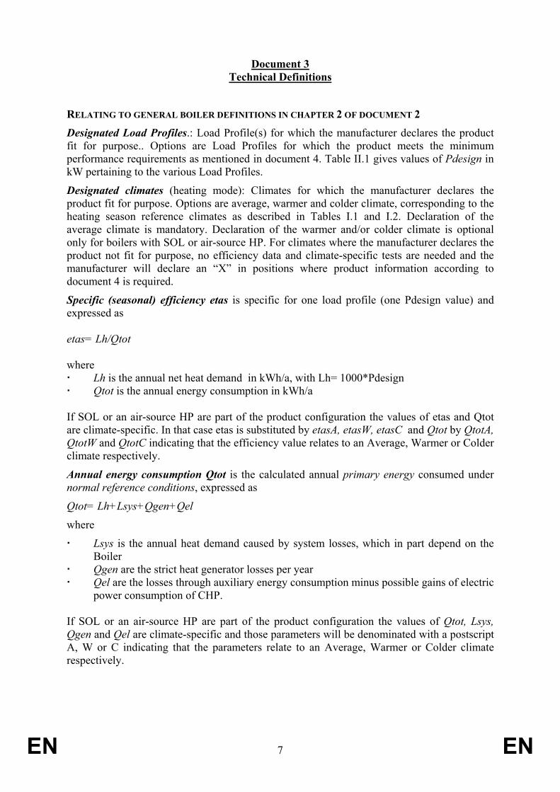
Document 3 Technical Definitions
RELATING TO GENERAL BOILER DEFINITIONS IN CHAPTER 2 OF DOCUMENT 2 Designated Load Profiles.: Load Profile(s) for which the manufacturer declares the product fit for purpose.. Options are Load Profiles for which the product meets the minimum performance requirements as mentioned in document 4. Table II.1 gives values of Pdesign in kW pertaining to the various Load Profiles.
Designated climates (heating mode): Climates for which the manufacturer declares the product fit for purpose. Options are average, warmer and colder climate, corresponding to the heating season reference climates as described in Tables I.1 and I.2. Declaration of the average climate is mandatory. Declaration of the warmer and/or colder climate is optional only for boilers with SOL or air-source HP. For climates where the manufacturer declares the product not fit for purpose, no efficiency data and climate-specific tests are needed and the manufacturer will declare an “X” in positions where product information according to document 4 is required.
Specific (seasonal) efficiency etas is specific for one load profile (one Pdesign value) and expressed as etas= Lh/Qtot where Lh is the annual net heat demand in kWh/a, with Lh= 1000*Pdesign Qtot is the annual energy consumption in kWh/a
If SOL or an air-source HP are part of the product configuration the values of etas and Qtot are climate-specific. In that case etas is substituted by etasA, etasW, etasC and Qtot by QtotA, QtotW and QtotC indicating that the efficiency value relates to an Average, Warmer or Colder climate respectively.
Annual energy consumption Qtot is the calculated annual primary energy consumed under normal reference conditions, expressed as
Qtot= Lh+Lsys+Qgen+Qel
where
Lsys is the annual heat demand caused by system losses, which in part depend on the Boiler
Qgen are the strict heat generator losses per year Qel are the losses through auxiliary energy consumption minus possible gains of electric
power consumption of CHP. If SOL or an air-source HP are part of the product configuration the values of Qtot, Lsys, Qgen and Qel are climate-specific and those parameters will be denominated with a postscript A, W or C indicating that the parameters relate to an Average, Warmer or Colder climate respectively.
EN 8 EN
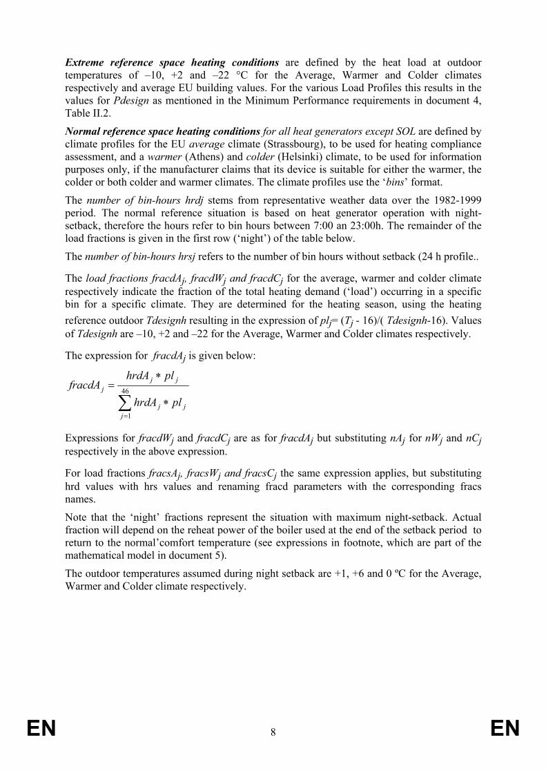
Extreme reference space heating conditions are defined by the heat load at outdoor temperatures of –10, +2 and –22 °C for the Average, Warmer and Colder climates respectively and average EU building values. For the various Load Profiles this results in the values for Pdesign as mentioned in the Minimum Performance requirements in document 4, Table II.2.
Normal reference space heating conditions for all heat generators except SOL are defined by climate profiles for the EU average climate (Strassbourg), to be used for heating compliance assessment, and a warmer (Athens) and colder (Helsinki) climate, to be used for information purposes only, if the manufacturer claims that its device is suitable for either the warmer, the colder or both colder and warmer climates. The climate profiles use the ‘bins’ format.
The number of bin-hours hrdj stems from representative weather data over the 1982-1999 period. The normal reference situation is based on heat generator operation with night-setback, therefore the hours refer to bin hours between 7:00 an 23:00h. The remainder of the load fractions is given in the first row (‘night’) of the table below.
The number of bin-hours hrsj refers to the number of bin hours without setback (24 h profile..
The load fractions fracdAj, fracdWj and fracdCj for the average, warmer and colder climate respectively indicate the fraction of the total heating demand (‘load’) occurring in a specific bin for a specific climate. They are determined for the heating season, using the heating reference outdoor Tdesignh resulting in the expression of plj= (Tj - 16)/( Tdesignh-16). Values of Tdesignh are –10, +2 and –22 for the Average, Warmer and Colder climates respectively.
The expression for fracdAj is given below:
∑=
∗
∗=
46
1
jjj
jjj
plhrdA
plhrdAfracdA
Expressions for fracdWj and fracdCj are as for fracdAj but substituting nAj for nWj and nCj respectively in the above expression.
For load fractions fracsAj, fracsWj and fracsCj the same expression applies, but substituting hrd values with hrs values and renaming fracd parameters with the corresponding fracs names.
Note that the ‘night’ fractions represent the situation with maximum night-setback. Actual fraction will depend on the reheat power of the boiler used at the end of the setback period to return to the normal’comfort temperature (see expressions in footnote, which are part of the mathematical model in document 5).
The outdoor temperatures assumed during night setback are +1, +6 and 0 ºC for the Average, Warmer and Colder climate respectively.
EN 9 EN
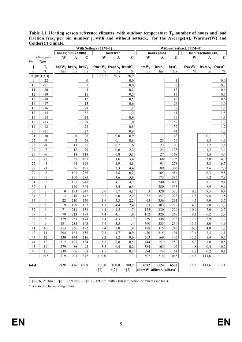
Table I.1. Heating season reference climates, with outdoor temperature Tj, number of hours and load fraction fracj per bin number j, with and without setback, for the Average(A), Warmer(W) andColder(C) climate. With Setback (TIM=1) Without Setback (TIM=0) hours(7.00-23.00h) load frac hours (24h) load fractions(24h)
climate--> W A C W A C W A C W A Cbin Tout
j Tj hrdWj hrdAj hrdCj fracdWj fracdAj fracdCj hrsWj hrsAj hrsCj fracsWj fracsAj fracsCj# °C hrs hrs hrs % % % hrs hrs hrs % % %
night[1,2,3] 36,2 30,3 26,9 9 -22 0 0,0 1 0,010 -21 1 0,0 6 0,311 -20 4 0,2 13 0,612 -19 11 0,5 17 0,713 -18 12 0,5 19 0,814 -17 15 0,6 26 1,015 -16 29 1,1 39 1,516 -15 32 1,2 41 1,517 -14 24 0,9 35 1,318 -13 29 1,0 52 1,819 -12 23 0,8 37 1,220 -11 27 0,9 41 1,321 -10 0 28 0,0 0,9 1 43 0,1 1,322 -9 2 28 0,1 0,8 25 54 1,3 1,623 -8 13 55 0,7 1,6 23 90 1,2 2,624 -7 12 79 0,6 2,2 24 125 1,2 3,425 -6 18 118 0,8 3,1 27 169 1,3 4,426 -5 35 137 1,6 3,4 68 195 3,0 4,927 -4 44 199 1,9 4,8 91 278 3,8 6,728 -3 56 195 2,3 4,4 89 306 3,6 7,029 -2 101 286 3,8 6,2 165 454 6,3 9,830 -1 100 285 3,6 5,8 173 385 6,2 7,831 0 121 243 4,1 4,7 240 490 8,1 9,432 1 170 364 5,4 6,5 280 533 8,9 9,633 2 0 193 247 0,0 5,7 4,1 3 320 380 0,3 9,5 6,434 3 2 218 142 0,2 6,0 2,2 22 357 228 1,8 9,8 3,535 4 22 210 150 1,6 5,3 2,2 63 356 261 4,7 9,0 3,736 5 19 190 182 1,3 4,4 2,4 63 303 279 4,3 7,0 3,737 6 71 211 138 4,4 4,5 1,7 175 330 229 10,9 7,0 2,738 7 79 213 179 4,4 4,1 1,9 162 326 269 9,1 6,2 2,939 8 129 253 174 6,4 4,3 1,7 259 348 233 12,9 5,9 2,240 9 181 235 165 7,9 3,5 1,4 360 335 230 15,7 5,0 1,941 10 253 236 192 9,4 3,0 1,4 428 315 243 16,0 4,0 1,742 11 294 163 156 9,1 1,7 0,9 430 215 191 13,4 2,3 1,143 12 330 144 116 8,2 1,2 0,6 503 169 146 12,5 1,4 0,744 13 312 123 134 5,8 0,8 0,5 444 151 150 8,3 1,0 0,545 14 279 86 93 3,5 0,4 0,2 384 105 97 4,8 0,4 0,246 15 238 66 58 1,5 0,1 0,1 294 74 61 1,8 0,2 0,1
>15 719 203 34* 100,0 802 214 106* 116,3 113,6 total 2928 3416 4368 100,0 100,0 100,0 4392 5124 6552 116,3 113,6 112,1 +[1] +[2] +[3] allhrsW allhrsA allhrsC [1]=+16,3*Ctim ; [2]=+13,6*Ctim ; [3]=+12,1*Ctim with Ctim is function of reheat (see text) * is also due to rounding errors
EN 10 EN
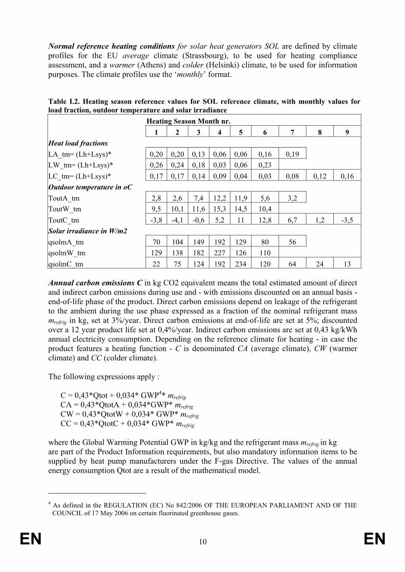
Normal reference heating conditions for solar heat generators SOL are defined by climate profiles for the EU average climate (Strassbourg), to be used for heating compliance assessment, and a warmer (Athens) and colder (Helsinki) climate, to be used for information purposes. The climate profiles use the ‘monthly’ format.
Table I.2. Heating season reference values for SOL reference climate, with monthly values for load fraction, outdoor temperature and solar irradiance Heating Season Month nr. 1 2 3 4 5 6 7 8 9 Heat load fractions LA_tm= (Lh+Lsys)* 0,20 0,20 0,13 0,06 0,06 0,16 0,19 LW_tm= (Lh+Lsys)* 0,26 0,24 0,18 0,03 0,06 0,23 LC_tm= (Lh+Lsys)* 0,17 0,17 0,14 0,09 0,04 0,03 0,08 0,12 0,16 Outdoor temperature in oC ToutA_tm 2,8 2,6 7,4 12,2 11,9 5,6 3,2 ToutW_tm 9,5 10,1 11,6 15,3 14,5 10,4 ToutC_tm -3,8 -4,1 -0,6 5,2 11 12,8 6,7 1,2 -3,5 Solar irradiance in W/m2 qsolmA_tm 70 104 149 192 129 80 56 qsolmW_tm 129 138 182 227 126 110 qsolmC_tm 22 75 124 192 234 120 64 24 13 Annual carbon emissions C in kg CO2 equivalent means the total estimated amount of direct and indirect carbon emissions during use and - with emissions discounted on an annual basis - end-of-life phase of the product. Direct carbon emissions depend on leakage of the refrigerant to the ambient during the use phase expressed as a fraction of the nominal refrigerant mass mrefrig in kg, set at 3%/year. Direct carbon emissions at end-of-life are set at 5%; discounted over a 12 year product life set at 0,4%/year. Indirect carbon emissions are set at 0,43 kg/kWh annual electricity consumption. Depending on the reference climate for heating - in case the product features a heating function - C is denominated CA (average climate), CW (warmer climate) and CC (colder climate). The following expressions apply :
C = 0,43*Qtot + 0,034* GWP4* mrefrig CA = 0,43*QtotA + 0,034*GWP* mrefrig CW = 0,43*QtotW + 0,034* GWP* mrefrig CC = 0,43*QtotC + 0,034* GWP* mrefrig
where the Global Warming Potential GWP in kg/kg and the refrigerant mass mrefrig in kg are part of the Product Information requirements, but also mandatory information items to be supplied by heat pump manufacturers under the F-gas Directive. The values of the annual energy consumption Qtot are a result of the mathematical model.
4 As defined in the REGULATION (EC) No 842/2006 OF THE EUROPEAN PARLIAMENT AND OF THE
COUNCIL of 17 May 2006 on certain fluorinated greenhouse gases.
EN 11 EN
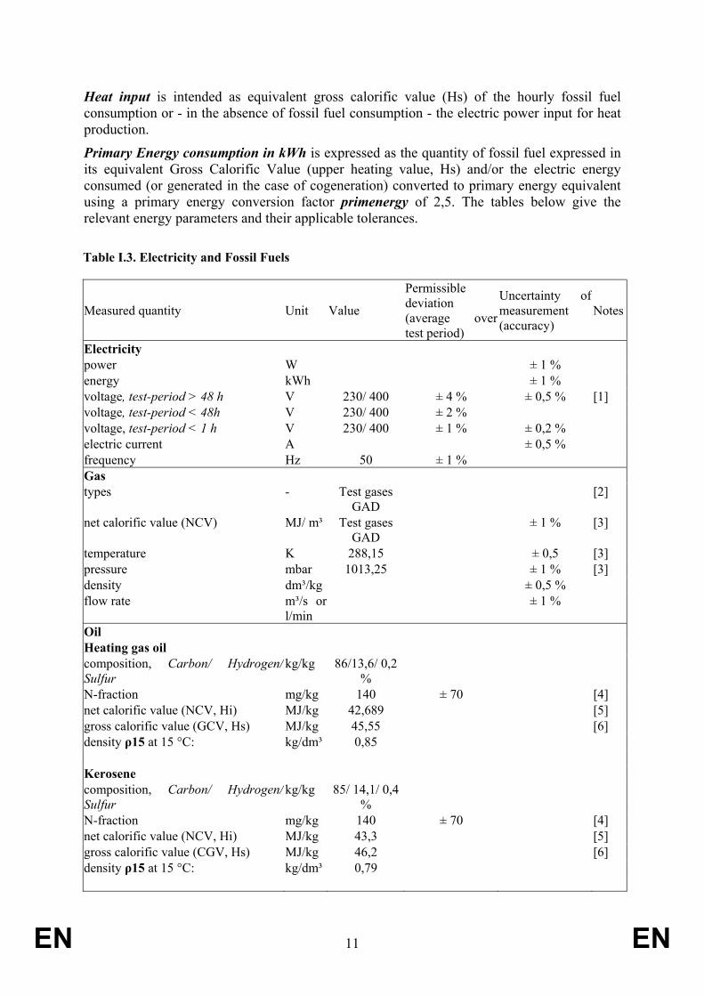
Heat input is intended as equivalent gross calorific value (Hs) of the hourly fossil fuel consumption or - in the absence of fossil fuel consumption - the electric power input for heat production.
Primary Energy consumption in kWh is expressed as the quantity of fossil fuel expressed in its equivalent Gross Calorific Value (upper heating value, Hs) and/or the electric energy consumed (or generated in the case of cogeneration) converted to primary energy equivalent using a primary energy conversion factor primenergy of 2,5. The tables below give the relevant energy parameters and their applicable tolerances.
Table I.3. Electricity and Fossil Fuels
Measured quantity Unit Value
Permissible deviation (average over test period)
Uncertainty of measurement (accuracy)
Notes
Electricity power W ± 1 % energy kWh ± 1 % voltage, test-period > 48 h V 230/ 400 ± 4 % ± 0,5 % [1] voltage, test-period < 48h V 230/ 400 ± 2 % voltage, test-period < 1 h V 230/ 400 ± 1 % ± 0,2 % electric current A ± 0,5 % frequency Hz 50 ± 1 % Gas types - Test gases
GAD [2]
net calorific value (NCV) MJ/ m³ Test gases GAD
± 1 % [3]
temperature K 288,15 ± 0,5 [3] pressure mbar 1013,25 ± 1 % [3] density dm³/kg ± 0,5 % flow rate m³/s or
l/min ± 1 %
Oil Heating gas oil composition, Carbon/ Hydrogen/ Sulfur
kg/kg 86/13,6/ 0,2 %
N-fraction mg/kg 140 ± 70 [4] net calorific value (NCV, Hi) MJ/kg 42,689 [5] gross calorific value (GCV, Hs) MJ/kg 45,55 [6] density ρ15 at 15 °C: kg/dm³ 0,85 Kerosene composition, Carbon/ Hydrogen/ Sulfur
kg/kg 85/ 14,1/ 0,4 %
N-fraction mg/kg 140 ± 70 [4] net calorific value (NCV, Hi) MJ/kg 43,3 [5] gross calorific value (CGV, Hs) MJ/kg 46,2 [6] density ρ15 at 15 °C: kg/dm³ 0,79

EN 12 EN
Notes: [1] Test periods >48 h apply to heat pump and/or solar assisted Products. Test periods <48 h apply
to conventional Products. Test period <1 h applies to the simplified test procedures for electric instantaneous water heaters
[2] Test gases as in the essential requirements of the Gas Appliances Directive 90/396/EEC with amendments as in 93/68/EC
[3] A factor K has to be applied to correct the calorific value for the actual average atmospheric pressure pa and gas pressure pg as well as the average gas temperature Tg over the test period. K = (pa + pg)/1013,25 + 288,15/(273,15+Tg)
[4] In case of low Sulfur test fuels,N-fractions lower than 70 mg/kg and lower S fractions are allowed
[5] Default value, if value is not determined calorimetrically. Also other values are defaults. Alternatively, if volumetric mass and sulphur content are known (e.g. by basic analysis) the net heating value (Hi) may be determined with Hi = 52,92 - (11,93 × ρ15 )- (0,3 - S) in MJ/kg
[6] Calculated from net calorific value with multiplier 1,067× GCV=1,067 × NCV
Table I.4. Characteristics of reference test gases, dry gas at 15°C and 1.013,25 mbar (illustrative) [1]
Gas family and group
Desig-nation
Composition by volume %
Net calorific value Hi in MJ/m³
Gross calorific value Hs in MJ/m³
Wobbe-index net Wi in MJ/m³
Wobbe-index gross Ws in MJ/m³
density in kg/m³ Test pressure
[2] nominal, minimum and maximum in Pa
pn pminpma
x 1st family Group a G 110 CH4 = 26
H2 = 50 N2 = 24
13,95 15,87 21,76 24,75 0,411 8 6 15
2nd family [3] Group H and Group E
G 20 CH4 = 100 34,02 37,78 45,67 50,72 0,555 20 17 25
Group L G 25 CH4 = 86 N2 = 14
29,25 32,49 37,38 41,52 0,612 25 20 30
3 rd family 29 25/
20 35 Groups B/P and
B [4] G 30 n-C4H10=50
i-C4H10=50 116,09 125,81 80,58 87,33 2,075
50 42,5 57,537 25 45 Group P G 31 C3H8 = 100 88,00 95,65 70,69 76,84 1,550 50 42,5 57,5

EN 13 EN
Notes:
[1] The definition, preparation and use of test gases is determined by the Essential Requirements of the Gas Appliances Directive. The table above reflects a momentary situation that may be subject to change and is for illustrative purposes only. It does not include limit gases and gases distributed nationally or locally.
[2] Test supply pressures when no test coupling exists. Note that for Groups B/P and P two sets of test pressures are available.
[3] Not shown is Group N (category I2N), which are as appliances using only second family gases at the prescribed supply pressure and that automatically adapt to all gases of the second family. They are tested with both G20 and G25 gases and both sets of pressure specifications.
[4] pmin = 25 Pa applies to group B/P; pmin=20 Pa applies to group B. Note That "LPG" is a mixture of 3rd family gases, usually tested with test gas Group B/P or B.
Solar energy contribution is the global solar irradiance G in W/m² on an optimally tilted collector surface with South orientation as defined in table II.2 multiplied with the solar heat generator efficiency characteristics as determined in accordance with document 5 and conditions described in Table I.5 below.
Table I.5. Solar energy parameters for solar collector tests. Set values and tolerances
Measured quantity Unit Value
Permissible deviation of the arithmetic mean values from set values
Permissible deviations of individual measured values from set values
Uncertainty of measurement (accuracy)
Notes
Solar collector (glazed)--> eta0, a1, a2 through least square curve fit for 4 x 4 test results; Asol Test solar irradiance (global G, short wave) W/m² >700 W/m² ± 50 W/m²
(test) ± 10 W/m²
(indoors) [1]
Diffuse solar irradiance (fraction of total G) % <30% [2] Thermal irradiance variation (indoors) W/m² ± 10 W/m² Fluid temperature at collector inlet/outlet °C/ K range 0-99 ºC ± 0,1 K ± 0,1 K [3] Fluid temperature difference inlet/outlet ± 0,05 K [4] Incidence angle (to normal) ° <20° ±2 %
(<20°) [5]
Air speed parallel to collector m/s 3 ± 1 m/s 0,5 m/s [6] Fluid flow rate (also for simulator) kg/s 0,02 kg/s per
m² collector aperture area
± 10 % between
tests
± 1 % (max dev in 1 test)
Tilt angle ° 45° Orientation NESW S ± 45° Collector area A (absorber, gross, aperture) m² ± 0,3 % Pipe heat loss of loop in test W/K <0,2 W/K

EN 14 EN
Notes:
[1] Measured by pyranometer, equivalent to Class I (ISO 9060) or better. With shading ring or pyrheliometer and provided with a dessicator. Regular inspection of the desiccator shall be observed. Test sample rate 30 s.
Pyranometer stays fixed in one test-point before data recording begins. Sensor shall be co-planar to collector ± 1°, at midheight of collector and receiving the same levels of direct, diffuse and reflected solar radiation as collector. When used with solar irradiance simulator minimize effect of infrared radiation at wavelength > 3µ
[2] If <30% can then be ignored (from EN 12975-2) [3] Measure within 200 mm of collector connection [4] Preferable accuracy ± 0,02 K
[5] Measured by simple device: spike normal to collector and reference circles on collector plane to read spike shadow.
[6] Measure 10 to 50 mm above collector, use artifical wind generator if < 2m/s. Check uniform distribution with anemometer. Temperature of artificial wind is ambient ± 1K.
Ambient heat energy contribution is depending on the source of the HP:
for air-source the outdoor air temperature as defined in the normal reference conditions in table II.1 and represented by test points as defined in document 5;
for brine-source an average liquid temperature of 0 ºC;
for water-source an average liquid temperature of 10 ºC;
for ventilation air source an air temperature of 20 ºC if the flow rate does not exceed values mentioned in the notes to Table I.6 below.
Table I.6. Energy inputs and related parameters ambient heat/ heat pumps
Measured quantity Unit [climate conditions]
Value
Permissible deviation (average over period
Permissible deviations of individual measured values
Uncertainty of measurement (accuracy)
Notes
Heat pump assistance: Liquid (heat transfer media: brine or water) brine inlet temperature °C 0 ± 0,2 ± 0,5 ± 0,1 water inlet temperature °C 10 volume flow m³/s or
l/min ± 2 % ± 5 % ± 5 %
static pressure difference Pa -- ± 10 % ± 5 Pa/ 5% [1] Heat pump assistance: Air (as heat source ) outdoor air temperature (dry bulb)
°C Table II.1 and
document 6
[2]
(Tout)
± 0,3 ± 1 ± 0,2
vent exhaust air temperature (Tex)
°C 20 ± 0,3 ± 1 ± 0,2
mixed air temperature (Tmix) °C see note ± 0,3 ± 1 ± 0,2 [3] inlet air humdity g H2O/ m³ 5,5 ± 5 % [4] volume flow dm³/s ± 5 % ± 10 % ± 5 % static pressure difference Pa -- ± 10 % ± 5 Pa/ 5% [5]

EN 15 EN
Notes: [1] maximum value according to manufacturer instructions shall be set at liquid pump outlet, at
nominal flow rate specified. Accuracy of measurement is ± 5 Pa if value < 100 Pa and 5% if value >100 Pa.
[2] Set values apply to electric or fossil fuel fired heat pumps. [3] In order to avoid over-ventilation a maximum availability of ventilation exhaust air at a temperature
of 20 ºC is assumed, depending on the Load Profile. This parameter ventex [in m³/h] is given below. If the actual nominal inlet air flow rate ventreal [in m³/h] exceeds this value, the heat pump shall use the mixed air temperature Tmix [in ºC] for testing. Tmix is determined from the relative proportion of exhaust air temperature Tex [in ºC] and exhaust air flow rate ventex versus outdoor air temperature Toutair and the surplus air flow (ventreal-ventex). In formula: Tmix = {Tex × ventex + Tout × (ventreal - ventex)} / ventreal
Default values ventex per water load profile: parameter unit 1 -XXS 2 -XS 3 -S 4 -M 5 -L 6 -XL 7 -XXL 8 -3XL 9 -4XL ventex m³/h 109 136 128 159 190 870 1021 2943 8830 If ventreal is not known a default value of 300 m³/kW nominal power of heat pump can be used.
Note that XXS applies to water heating only. [4] Note that an absolute humidity of 5,5 g/m³ results in 37% Relative Humidity at 20 ºC dry bulb (12
ºC wet bulb), 65% RH at 10 ºC dry bulb (9 ºC wet bulb), etc. [5] maximum value according to manufacturer instructions shall be set at duct outlet, with heat pump
not operating. Nominal air flow shall be verified. Accuracy of measurement is ± 5 Pa is value is < 100 Pa and 5% if value >100 Pa.
RELATING TO BOILER PRODUCT CONFIGURATION (BOOLEAN AND INTEGERS) Relating to Data Inputs document 4, Table II.4.
SOL, HP, ELBU, FOS, FOSB, CHP are not only the denominations of the heat generators mentioned in Article 2 but also Boolean parameters (values ‘y’=1; ‘n’=0) indicating whether (value ‘y’=1) or not (value ‘n’=0) the heat generators of these types are part of the product configuration.
Timer (TIM): Design option of a heating regime whereby the boiler is shut down during a setback-period of 8 hours minus the time (in h) necessary to reheat the space temperature again from setback level to its normal comfort level. To apply this design option the timer parameter must be declared (TIM=yes=1) and the reheat power (parameter reheat) as a fraction of nominal radiator capacity Pradnom. Timer is a declared parameter and does not require the physical presence of a timing device in the Product;
System Buffer (BUF): Primary storage tank. If the configuration includes a primary storage tank the Boolean parameter BUF must be set to BUF=1 (otherwise BUF=0) and the manufacturer shall declare its volume Vbuf in litres and standing losses Psbbuf in W at a temperature difference between store and ambient of 40 K. Also in case ELBU is the only heat generator and using a store with volume >4 litres BUF=1 and standing losses will be declared as Psbbuf.
Combi (parameter SOLCOMBI, HPCOMBI) indicates whether the Boiler is also a Combi-boiler, to be declared only in case SOL or HP is part of the product configuration.
Load profile water heating (waterload) is the declared load profile for the Combi-boiler, characterised by the Qref values in Table III.2.
EN 16 EN
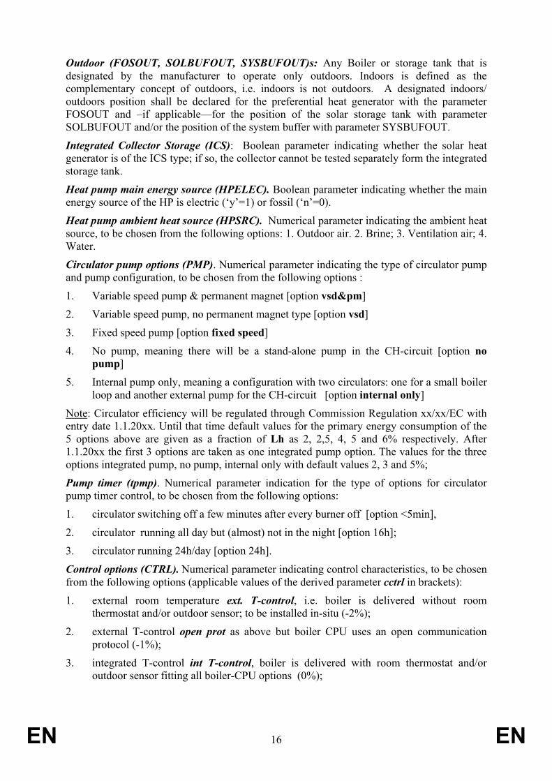
Outdoor (FOSOUT, SOLBUFOUT, SYSBUFOUT)s: Any Boiler or storage tank that is designated by the manufacturer to operate only outdoors. Indoors is defined as the complementary concept of outdoors, i.e. indoors is not outdoors. A designated indoors/ outdoors position shall be declared for the preferential heat generator with the parameter FOSOUT and –if applicable—for the position of the solar storage tank with parameter SOLBUFOUT and/or the position of the system buffer with parameter SYSBUFOUT.
Integrated Collector Storage (ICS): Boolean parameter indicating whether the solar heat generator is of the ICS type; if so, the collector cannot be tested separately form the integrated storage tank.
Heat pump main energy source (HPELEC). Boolean parameter indicating whether the main energy source of the HP is electric (‘y’=1) or fossil (‘n’=0).
Heat pump ambient heat source (HPSRC). Numerical parameter indicating the ambient heat source, to be chosen from the following options: 1. Outdoor air. 2. Brine; 3. Ventilation air; 4. Water.
Circulator pump options (PMP). Numerical parameter indicating the type of circulator pump and pump configuration, to be chosen from the following options :
1. Variable speed pump & permanent magnet [option vsd&pm]
2. Variable speed pump, no permanent magnet type [option vsd]
3. Fixed speed pump [option fixed speed]
4. No pump, meaning there will be a stand-alone pump in the CH-circuit [option no pump]
5. Internal pump only, meaning a configuration with two circulators: one for a small boiler loop and another external pump for the CH-circuit [option internal only]
Note: Circulator efficiency will be regulated through Commission Regulation xx/xx/EC with entry date 1.1.20xx. Until that time default values for the primary energy consumption of the 5 options above are given as a fraction of Lh as 2, 2,5, 4, 5 and 6% respectively. After 1.1.20xx the first 3 options are taken as one integrated pump option. The values for the three options integrated pump, no pump, internal only with default values 2, 3 and 5%;
Pump timer (tpmp). Numerical parameter indication for the type of options for circulator pump timer control, to be chosen from the following options:
1. circulator switching off a few minutes after every burner off [option <5min],
2. circulator running all day but (almost) not in the night [option 16h];
3. circulator running 24h/day [option 24h].
Control options (CTRL). Numerical parameter indicating control characteristics, to be chosen from the following options (applicable values of the derived parameter cctrl in brackets):
1. external room temperature ext. T-control, i.e. boiler is delivered without room thermostat and/or outdoor sensor; to be installed in-situ (-2%);
2. external T-control open prot as above but boiler CPU uses an open communication protocol (-1%);
3. integrated T-control int T-control, boiler is delivered with room thermostat and/or outdoor sensor fitting all boiler-CPU options (0%);

EN 17 EN
4. integrated double temperature outlet double TV, boiler is delivered with two outlets of which the temperatures (T) and volume flow rates (V) can be regulated individually and independently, with the option to create a temperature difference between the two outlets of at least 20 K (+2%);
5. integrated multi-zone/radiator outlets multi TV, boiler is delivered with three or more heating water outlets of which the temperatures (T) and volume flow rates (V) can be regulated individually and independently, with the option to create a temperature difference between the outlets of at least 10 K (+4%).
RELATING TO PRODUCT CONFIGURATION (NUMERICAL) Solar collector aperture area (Asol) in m² is the collector area as established according to Best Testing Practice.
Solar tank volume (Vsol) in ltr. is the volume of the (solar part of) the solar storage tank as established according to Best Testing Practice.
Heat transfer rate of the solar tank heat exchanger (UAsol) in W/K is the maximum heat transfer of the heat exchanger in the solar tank per degree of temperature difference between heat exchanger inlet and outlet temperature as established according to Best Testing Practice. Instead of a test result a default value of 40*Asol may be used.
Binlimit in ºC is the declared minimum outdoor temperature in ºC required for heat pump operation.
Turndown ratio (td, tdb, HPtd): declared ratio between the declared minimum and maximum heat input for FOS (td) and FOSB (tdb) or ratio between declared minimum and maximum heat output for HP (HPtd), whereby the latter is determined for a HP tested at +12 ºC outdoor temperature.
Maximum heat input (Pinmax, Pinmaxb) in kW is the declared maximum fossil fuel input in equivalent Gross Calorific Value of the fuel per hour for FOS (Pinmax) and FOSB (Pinmaxb).
Reheat is the declared ratio between the heating power output for reheating after night setback and the nominal radiator capacity of the specific load profile.
Buffer tank volume (Vbuf) in ltr. is the volume of the primary storage tank as established according to Best Testing Practice.
RELATING TO BOILER MAIN EFFICIENCY TESTS
Test point: Set of test conditions –energy input, ambient, etc.—at which to determine heating power output and energy efficiency of a heat generator through physical tests in accordance with document 5.
Test results are power and/or efficiency values resulting from tests at test points. In Table II.4 the following test values determined in accordance with document 5 are required:
for HP the heat pump heating power outputs Php and the Coefficient of Performance COP (ratio between HP energy output and input; for other types of heat generators generally known as ‘efficiency’);
for FOS the efficiency values _eta;
for FOSB the efficiency values _etab (FOSB efficiency);
EN 18 EN
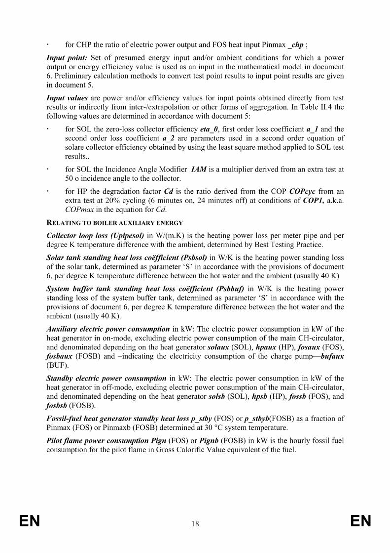
for CHP the ratio of electric power output and FOS heat input Pinmax _chp ;
Input point: Set of presumed energy input and/or ambient conditions for which a power output or energy efficiency value is used as an input in the mathematical model in document 6. Preliminary calculation methods to convert test point results to input point results are given in document 5.
Input values are power and/or efficiency values for input points obtained directly from test results or indirectly from inter-/extrapolation or other forms of aggregation. In Table II.4 the following values are determined in accordance with document 5:
for SOL the zero-loss collector efficiency eta_0, first order loss coefficient a_1 and the second order loss coefficient a_2 are parameters used in a second order equation of solare collector efficiency obtained by using the least square method applied to SOL test results..
for SOL the Incidence Angle Modifier IAM is a multiplier derived from an extra test at 50 o incidence angle to the collector.
for HP the degradation factor Cd is the ratio derived from the COP COPcyc from an extra test at 20% cycling (6 minutes on, 24 minutes off) at conditions of COP1, a.k.a. COPmax in the equation for Cd.
RELATING TO BOILER AUXILIARY ENERGY Collector loop loss (Upipesol) in W/(m.K) is the heating power loss per meter pipe and per degree K temperature difference with the ambient, determined by Best Testing Practice.
Solar tank standing heat loss coëfficient (Psbsol) in W/K is the heating power standing loss of the solar tank, determined as parameter ‘S’ in accordance with the provisions of document 6, per degree K temperature difference between the hot water and the ambient (usually 40 K)
System buffer tank standing heat loss coëfficient (Psbbuf) in W/K is the heating power standing loss of the system buffer tank, determined as parameter ‘S’ in accordance with the provisions of document 6, per degree K temperature difference between the hot water and the ambient (usually 40 K).
Auxiliary electric power consumption in kW: The electric power consumption in kW of the heat generator in on-mode, excluding electric power consumption of the main CH-circulator, and denominated depending on the heat generator solaux (SOL), hpaux (HP), fosaux (FOS), fosbaux (FOSB) and –indicating the electricity consumption of the charge pump—bufaux (BUF).
Standby electric power consumption in kW: The electric power consumption in kW of the heat generator in off-mode, excluding electric power consumption of the main CH-circulator, and denominated depending on the heat generator solsb (SOL), hpsb (HP), fossb (FOS), and fosbsb (FOSB).
Fossil-fuel heat generator standby heat loss p_stby (FOS) or p_stbyb(FOSB) as a fraction of Pinmax (FOS) or Pinmaxb (FOSB) determined at 30 °C system temperature.
Pilot flame power consumption Pign (FOS) or Pignb (FOSB) in kW is the hourly fossil fuel consumption for the pilot flame in Gross Calorific Value equivalent of the fuel.

EN 19 EN
OTHER BOILER-RELATED DEFINITIONS Variable capacity heat generator: heat generator with the capability to vary power output the (fuel burning rate, compressor speed, etc.) whilst maintaining continuous operation. For electric heat pumps also known as ‘heat pump with inverter’;
Staged capacity heat generator: a heat generator with the capability to vary power output the (fuel burning rate, compressor speed, etc.) between two discrete power levels whilst maintaining continuous operation. This includes boilers with alternative burning rates set once only at the time of installation, referred to as range rating;
Fixed capacity heat generator: a heat generator without the capability to vary power output the (fuel burning rate, compressor speed, etc.) whilst maintaining continuous operation. This includes boilers with alternative burning rates set once only at the time of installation, referred to as range rating;
Recoverable heat loss: part of the heat loss from the space heating system, which may be recovered to lower the heat demand for space heating. Recoverable are for instance certain envelope losses of heat generator, system buffer, solar tank and auxiliary electric devices. Not recoverable are for instance flue gas losses, fuel losses and electricity generation losses;
Recovered heat loss: part of the recoverable heat loss that contributes to meet the heat demand of the space;
Heat recovery rate is the ratio between recoverable and recovered heat loss. The heat recovery rate depends on timing and location of the recoverable heat losses versus timing and location of the heat demand.
Note: The default heat recovery rate for parts placed indoors is 0,55 and 0 when placed outdoors. Internal parameters are boilrecov, solrecov, bufrecov and auxrecov to indicate the heat recovery rate for fossil fuel fired heat generators, solar tank standing losses, system buffer standing losses and heat from auxiliary electricity consuming devices.
Space heating fraction (usesol, usehp) is the share of the solar and heat pump generator energy output in the heating season partitioned to space heating in case of a combi-boiler, determined by the ratio between the space heating demand Lh and the total heating demand for space and water heating Lh+Lw in the heating season;
Default: Any feature or parameter value of the Product that is used as a basic reference. It does not require verification, i.e. it does not require the feature to be implemented and/or the parameter value to be valid;
Uncertainty of measurement or measurement accuracy is the capacity of the measurement instruments to capture the actual value of the physical parameter, expressed as maximum allowable error.
Permissible deviations of individual measured values is maximum/minimum permissible peak value of the physical parameter measured during the test in order for a test sample to be valid .
Permissible deviations of the average value over the test period (and/or the total of test samples) is the maximum/minimum permissable deviation from the prescribed setpoint of the average measured value of the physical parameter over a single test period.
Note: Usually this is the value intended if harmonised standards refer to a measurement tolerance in generic terms.

EN 20 EN
RELATING TO COMBI-BOILER DEFINITIONS IN CHAPTER 2 OF DOCUMENT 2 Specific efficiency for water heating etawh of combi-boilers is specific for the designated water heating load profile (one Pdesign value) and expressed as
atotcombi
ref
etawh∗∗
=3666,0
where Qref is the reference heat demand (energy content of hot water) in kWh/d for the
designated water heating profile (see values in document 4, table II.2); Qatotcombi is the annual water heating energy consumption of combi-boiler in kWh/a,
with Qatotcombi = Qatot – combicomp - combitrans
where Qatot is the annual energy consumption in kWh/a as defined in Commission
Regulation XX/XX/EC; combicomp in kWh/a is the heat gain for water heating from the net annual boiler
envelope losses (discounted for heat recovery) Qenvon as calculated in document 6 for the highest declared space heating load profile;
combitrans in kWh/a is the heat gain from Passive Flue Heat Recovery Devices, i.e. devices recovering flue gas waste heat in space heating mode for use in water heating mode, determined in accordance with document 5.
If SOL or an air-source HP are part of the product configuration the values of etawh, Qatotcombi , Qatot , combicomp and combitransare climate-specific. In that case etawh is substituted by etawhA, etawhW, etawhC and Qatot by QatotA, QatotW and QatotC , etc. indicating that the efficiency value relates to an Average, Warmer or Colder climate respectively.

EN 21 EN
Mathematical operators and expressions
+. -, *, / addition, subtraction, multiplication, division
[X1; X2] array (one-dimensional, with 2 elements X1 and X2)
MIN (X;Y) if Y < X then Y else X
MAX (X;Y) if Y > X then Y else X
SUM(X;Y) X+Y
SUM(X) if X is an array: sum of all elements in the array. If the elements of the array areindexed, e.g. with index tp and 7 elements then the classic notation is sigma
MIN(X;MAX(Y;Z)) X< Y <Z
POWER (X;Y) or X^Y X to the power Y ( XY)
LN (X) natural logarithm of X
SIN (X) sinus of X
COS (X) cosinus of X
TAN (X) tangent of X
SQRT(SUMX2PY2(X;Y)) square root of the sum of the square of X and the square of Y;
√ (X² + Y²)
IF(A;X;Y) IF expression A is True THEN X else Y (X and Y can be values or expressions)
IF(A;X;IF(C;Y;Z)) Nested IF..THEN statement: If expression A is True then X else if expression Cis True then Y else Z. Represented by a table:
CHOOSE (X;Y) X is rank number choosing element of array Y with that index
MATCH(X; A1:A3) Result: Closest lower value matching X in array A1:A3 (cells A1, A2, A3)
INDEX([X1;X2]; X;Y) Returns a value from a position in an array (X position only) or a table (X and Ypositions)
EN 22 EN
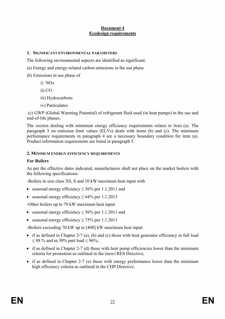
Document 4 Ecodesign requirements
1. SIGNIFICANT ENVIRONMENTAL PARAMETERS The following environmental aspects are identified as significant:
(a) Energy and energy-related carbon emissions in the use phase
(b) Emissions in use phase of
i) NOx
ii) CO
iii) Hydrocarbons
iv) Particulates
(c) GWP (Global Warming Potential) of refrigerant fluid used (in heat pumps) in the use and end-of-life phases.
The section dealing with minimum energy efficiency requirements relates to item (a). The paragraph 3 on emission limit values (ELVs) deals with items (b) and (c). The minimum performance requirements in paragraph 4 are a necessary boundary condition for item (a). Product information requirements are listed in paragraph 5.
2. MINIMUM ENERGY EFFICIENCY REQUIREMENTS
For Boilers As per the effective dates indicated, manufacturers shall not place on the market boilers with the following specifications:
-Boilers in size class XS, S and 10 kW maximum heat input with
• seasonal energy efficiency ≤ 56% per 1.1.2011 and
• seasonal energy efficiency ≤ 64% per 1.1.2013
-Other boilers up to 70 kW maximum heat input:
• seasonal energy efficiency ≤ 56% per 1.1.2011 and
• seasonal energy efficiency ≤ 75% per 1.1.2013
-Boilers exceeding 70 kW up to [400] kW maximum heat input:
• if as defined in Chapter 2-7 (a), (b) and (c) those with heat generator efficiency in full load ≤ 88 % and in 30% part load ≤ 96%;
• if as defined in Chapter 2-7 (d) those with heat pump efficiencies lower than the minimum criteria for promotion as outlined in the (new) RES Directive;
• if as defined in Chapter 2-7 (e) those with energy performance lower than the minimum high efficiency criteria as outlined in the CHP Directive.

EN 23 EN
Additional requirements for the placing on the market of boilers exceeding 70 kW maximum heat input are:
1. As from 1/1/2013 Boilers with heat generation only by combustion of gaseous and/or liquid fuels may only be installed if the heating system also includes controls and other components which bring the overall energy heating system efficiency rating above 96% (Local or National legislation may specify a higher level). This will imply the use of renewables or high efficiency cogeneration.
2. Boilers shall be placed on the market with monitoring equipment (including data recording) allowing real life efficiency of the heat emitter (and emissions) to be estimated for compliance assessment of the installation with applicable regulations.
Recording:
• Water feed and return temperatures, • water flow rates (pump settings), • energy input(from burner settings) • Flue gas monitoring (CO/CO2/O2 + temperature etc.)
This should include a suitable interface (e.g. GSM protocol) allowing equipment owner, enforcement authorities, etc. to download data periodically, once a suitable standard for this purpose shall have been published in the Official Journal to ensure interoperability. A mandate for such a harmonised standard will be issued with a view to achieve interoperability.
In the context of the EPBD, for boilers exceeding 70 kW up to [400] kW maximum heat input, furthermore a minimum seasonal energy efficiency requirement of 75 % per 1.1.2011 and 95 % per 1.1.2013 should be considered by the Member States.
For Combi-boilers
The table below gives the minimum specific efficiency etawh in %. The efficiency is to be determined in accordance with Commission Regulation XX/XX/EC, corrected in accordance with the provisions in document 5.
Table II.1 . MEPS for Combi-boiler, minimum specific efficiency etawh in %
Load profile water heating XXS XS S M L XL XXL 3XL 4XL
From 1.1.2011 29 32 32 39 46 50 60 64 64
From 1.1.2013 32 35 35 45 56 62 72 80 86
For Cylinders From 1 January 2011, the requirement on standing loss is as follows
S < 20+0,25 x V
Where
S is the standing loss in Watts

EN 24 EN
V is the nominal capacity in litres
Standing loss is assessed for an ambient temperature of 20 °C and a hot water temperature of 60 °C according to Best Testing Practice.
Note: Most common and acceptable is the measurement of the electric power consumption of an immersed electric water heater (added or already incorporated) at thermal equilibrium for the temperatures mentioned. Alternatively, the storage tank with 20 °C water (ambient) may be charged to a set temperature of 60 °C and the energy input is measured. After 24h the tank is discharged and the energy content (temperature, volume) of the hot water (with reference to ambient) is measured. The difference between the two measurements, divided by 24h, is the standing loss in W.
Guidance documents for compliance assessment are given in document 7.
3. EMISSION LIMIT VALUES The following emissions in the use phase are identified as significant:
NOx
CO
Hydrocarbons
Particulates
Refrigerant fluids in heat pumps
For NOx emissions in the use phase of Boilers during space heating, assessed according to best testing practice the following emission limit values will apply:
From 01/01/2013: 50 mg/kWh for gas boilers
From 01/01/2014: 105 mg/kWh for oil boilers
For boilers with electricity output (that is, cogeneration units) a credit for displaced NOx from central power plants and avoided grid losses will be added to the amount of admissible NOx emissions5:
From 01/01/2013: 50 mg/kWh for gas Gross Caloric Value input
From 01/01/2013: 75 mg/kWh for oil Gross Caloric Value input
For NOx emissions in the use phase of Combi-boilers during water heating, assessed according to best testing practice the emission limit values of Dedicated Water Heaters as defined in Commission Regulation XX/XX/EC will apply. The same NOx credit as indicated above can be applied for the electricity produced during water heating by cogeneration Combi-boilers.
5 Based on the emission values in the Directive on Large Combustion Plants for gas power plants in the range of
50-500MW and assuming an electric output of 15 % as in the best Stirling engines.

EN 25 EN
For emissions of CO, hydrocarbons and particulates current harmonised measurement methods should be improved as they currently only address steady state mode. The general requirements under the product safety and gas appliance Directives shall apply where applicable to the covered products.
The Commission will issue a mandate to the harmonisation bodies to develop appropriate measurement standards.
4. MINIMUM PERFORMANCE REQUIREMENTS In order to avoid negative impact on the functionality of the product in accordance with Art. 15, sub x of 2005/32/EC, the following will apply:
For Boilers the maximum power output under design conditions Pmaxdesign shall be higher than or equal to the design power Pdesign of the space heating Load Profile(s) declared.
Pmaxdesign is to be determined in accordance with document 6.
Values of Pdesign are given in the table below
Table II.2
Load Profile space heating XS S M L XL XXL 3XL 4XL
Pdesign in kW 3,5 5,3 8 12 18 27 41 60
For Load Profiles up to XXL, the maximum heat input is 70 kW. For Load Profiles 3XL and 4 XL the maximum heat input is 100 and 150 kW respectively.
Combi-boilers must be able to meet all requirements of the tapping profile as defined in Commission Regulation XX/XX/EC on Dedicated Water Heaters, pertaining to water heating Load Profile declared.
For illustrative purposes the table below recites Commission Regulation xx/xx regarding the daily heating energy content of the hot water to be delivered Qref.
Table II.3
Load Profile water heating XXS XS S M L XL XXL 3XL 4XL
Qref in kWh/d 2,1 2,1 2,1 5,85 11,7 19,1 24,5 46,8 93,52
All products in the scope will be subject to a "fit for purpose" (see Chapter 2-15) evaluation in line with the product definitions in Article 2 and according to Best Testing Practice.
EN 26 EN
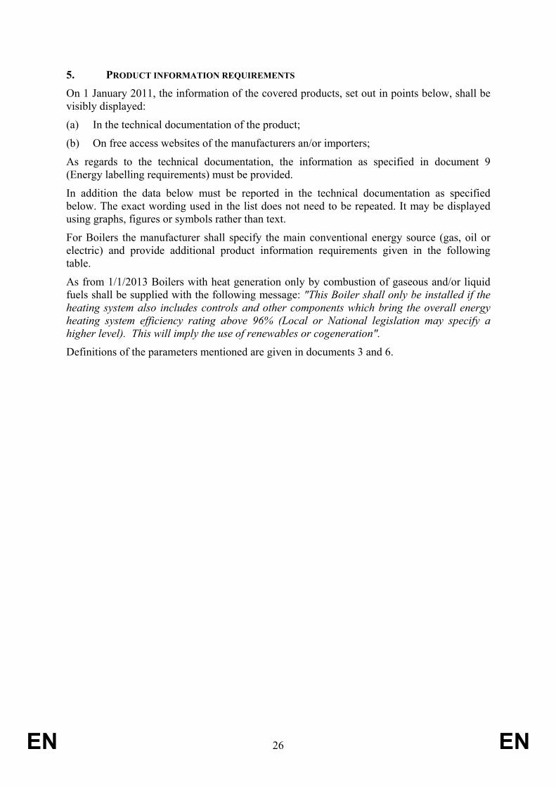
5. PRODUCT INFORMATION REQUIREMENTS On 1 January 2011, the information of the covered products, set out in points below, shall be visibly displayed:
(a) In the technical documentation of the product;
(b) On free access websites of the manufacturers an/or importers;
As regards to the technical documentation, the information as specified in document 9 (Energy labelling requirements) must be provided.
In addition the data below must be reported in the technical documentation as specified below. The exact wording used in the list does not need to be repeated. It may be displayed using graphs, figures or symbols rather than text.
For Boilers the manufacturer shall specify the main conventional energy source (gas, oil or electric) and provide additional product information requirements given in the following table.
As from 1/1/2013 Boilers with heat generation only by combustion of gaseous and/or liquid fuels shall be supplied with the following message: "This Boiler shall only be installed if the heating system also includes controls and other components which bring the overall energy heating system efficiency rating above 96% (Local or National legislation may specify a higher level). This will imply the use of renewables or cogeneration".
Definitions of the parameters mentioned are given in documents 3 and 6.
EN 27 EN
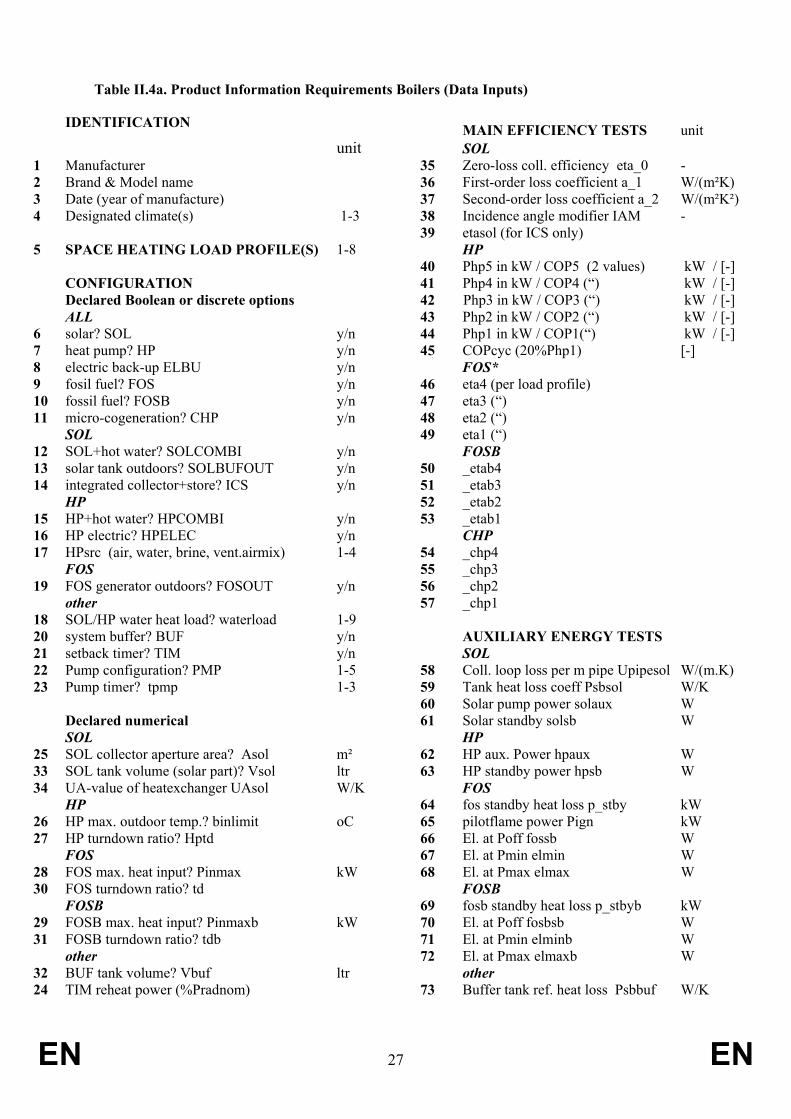
Table II.4a. Product Information Requirements Boilers (Data Inputs)
IDENTIFICATION MAIN EFFICIENCY TESTS unit unit SOL 1 Manufacturer 35 Zero-loss coll. efficiency eta_0 - 2 Brand & Model name 36 First-order loss coefficient a_1 W/(m²K) 3 Date (year of manufacture) 37 Second-order loss coefficient a_2 W/(m²K²) 4 Designated climate(s) 1-3 38 Incidence angle modifier IAM - 39 etasol (for ICS only) 5 SPACE HEATING LOAD PROFILE(S) 1-8 HP 40 Php5 in kW / COP5 (2 values) kW / [-] CONFIGURATION 41 Php4 in kW / COP4 (“) kW / [-] Declared Boolean or discrete options 42 Php3 in kW / COP3 (“) kW / [-] ALL 43 Php2 in kW / COP2 (“) kW / [-] 6 solar? SOL y/n 44 Php1 in kW / COP1(“) kW / [-] 7 heat pump? HP y/n 45 COPcyc (20%Php1) [-] 8 electric back-up ELBU y/n FOS* 9 fosil fuel? FOS y/n 46 eta4 (per load profile) 10 fossil fuel? FOSB y/n 47 eta3 (“) 11 micro-cogeneration? CHP y/n 48 eta2 (“) SOL 49 eta1 (“) 12 SOL+hot water? SOLCOMBI y/n FOSB 13 solar tank outdoors? SOLBUFOUT y/n 50 _etab4 14 integrated collector+store? ICS y/n 51 _etab3 HP 52 _etab2 15 HP+hot water? HPCOMBI y/n 53 _etab1 16 HP electric? HPELEC y/n CHP 17 HPsrc (air, water, brine, vent.airmix) 1-4 54 _chp4 FOS 55 _chp3 19 FOS generator outdoors? FOSOUT y/n 56 _chp2 other 57 _chp1 18 SOL/HP water heat load? waterload 1-9 20 system buffer? BUF y/n AUXILIARY ENERGY TESTS 21 setback timer? TIM y/n SOL 22 Pump configuration? PMP 1-5 58 Coll. loop loss per m pipe Upipesol W/(m.K) 23 Pump timer? tpmp 1-3 59 Tank heat loss coeff Psbsol W/K 60 Solar pump power solaux W Declared numerical 61 Solar standby solsb W SOL HP 25 SOL collector aperture area? Asol m² 62 HP aux. Power hpaux W 33 SOL tank volume (solar part)? Vsol ltr 63 HP standby power hpsb W 34 UA-value of heatexchanger UAsol W/K FOS HP 64 fos standby heat loss p_stby kW 26 HP max. outdoor temp.? binlimit oC 65 pilotflame power Pign kW 27 HP turndown ratio? Hptd 66 El. at Poff fossb W FOS 67 El. at Pmin elmin W 28 FOS max. heat input? Pinmax kW 68 El. at Pmax elmax W 30 FOS turndown ratio? td FOSB FOSB 69 fosb standby heat loss p_stbyb kW 29 FOSB max. heat input? Pinmaxb kW 70 El. at Poff fosbsb W 31 FOSB turndown ratio? tdb 71 El. at Pmin elminb W other 72 El. at Pmax elmaxb W 32 BUF tank volume? Vbuf ltr other 24 TIM reheat power (%Pradnom) 73 Buffer tank ref. heat loss Psbbuf W/K
EN 28 EN
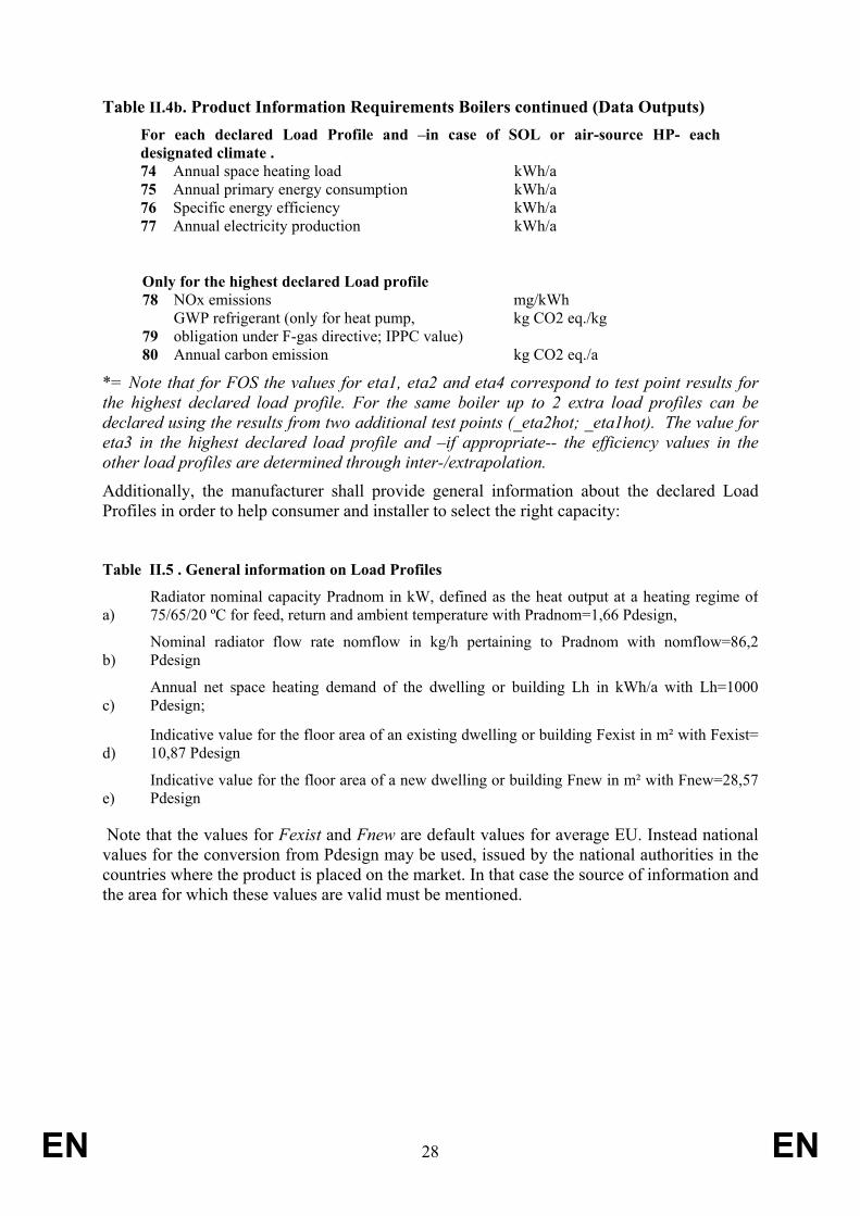
Table II.4b. Product Information Requirements Boilers continued (Data Outputs) For each declared Load Profile and –in case of SOL or air-source HP- each designated climate . 74 Annual space heating load kWh/a 75 Annual primary energy consumption kWh/a 76 Specific energy efficiency kWh/a 77 Annual electricity production kWh/a
Only for the highest declared Load profile 78 NOx emissions mg/kWh
79 GWP refrigerant (only for heat pump, obligation under F-gas directive; IPPC value)
kg CO2 eq./kg
80 Annual carbon emission kg CO2 eq./a
*= Note that for FOS the values for eta1, eta2 and eta4 correspond to test point results for the highest declared load profile. For the same boiler up to 2 extra load profiles can be declared using the results from two additional test points (_eta2hot; _eta1hot). The value for eta3 in the highest declared load profile and –if appropriate-- the efficiency values in the other load profiles are determined through inter-/extrapolation.
Additionally, the manufacturer shall provide general information about the declared Load Profiles in order to help consumer and installer to select the right capacity:
Table II.5 . General information on Load Profiles
a) Radiator nominal capacity Pradnom in kW, defined as the heat output at a heating regime of75/65/20 ºC for feed, return and ambient temperature with Pradnom=1,66 Pdesign,
b) Nominal radiator flow rate nomflow in kg/h pertaining to Pradnom with nomflow=86,2Pdesign
c) Annual net space heating demand of the dwelling or building Lh in kWh/a with Lh=1000Pdesign;
d) Indicative value for the floor area of an existing dwelling or building Fexist in m² with Fexist=10,87 Pdesign
e) Indicative value for the floor area of a new dwelling or building Fnew in m² with Fnew=28,57Pdesign
Note that the values for Fexist and Fnew are default values for average EU. Instead national values for the conversion from Pdesign may be used, issued by the national authorities in the countries where the product is placed on the market. In that case the source of information and the area for which these values are valid must be mentioned.
EN 29 EN
Document 5
Testing Methods
This section deals with the specification of test points and test results defined in document 3 and referenced in the Product Information Requirements in Document 4. Also it specifies preliminary calculation methods to derive input data for input points as required in the energy efficiency calculation in document 6.
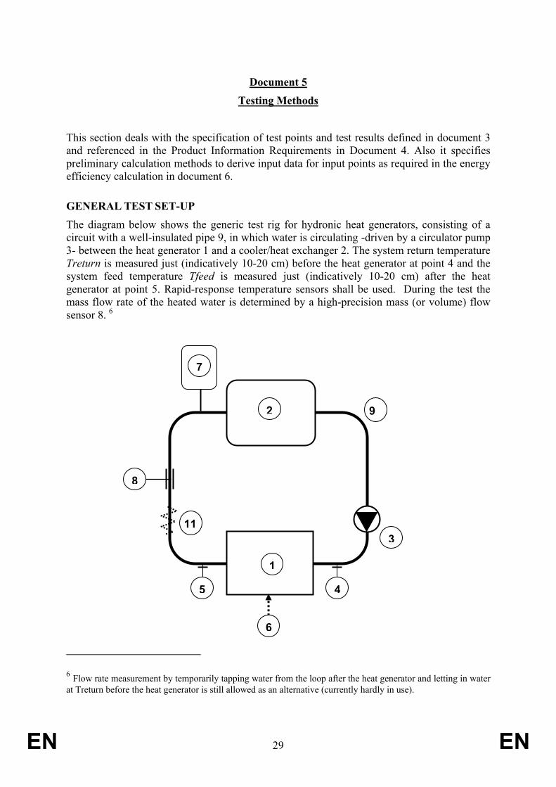
GENERAL TEST SET-UP The diagram below shows the generic test rig for hydronic heat generators, consisting of a circuit with a well-insulated pipe 9, in which water is circulating -driven by a circulator pump 3- between the heat generator 1 and a cooler/heat exchanger 2. The system return temperature Treturn is measured just (indicatively 10-20 cm) before the heat generator at point 4 and the system feed temperature Tfeed is measured just (indicatively 10-20 cm) after the heat generator at point 5. Rapid-response temperature sensors shall be used. During the test the mass flow rate of the heated water is determined by a high-precision mass (or volume) flow sensor 8. 6
6 Flow rate measurement by temporarily tapping water from the loop after the heat generator and letting in water at Treturn before the heat generator is still allowed as an alternative (currently hardly in use).
1
2
3
8
45
6
7
9
11
EN 30 EN
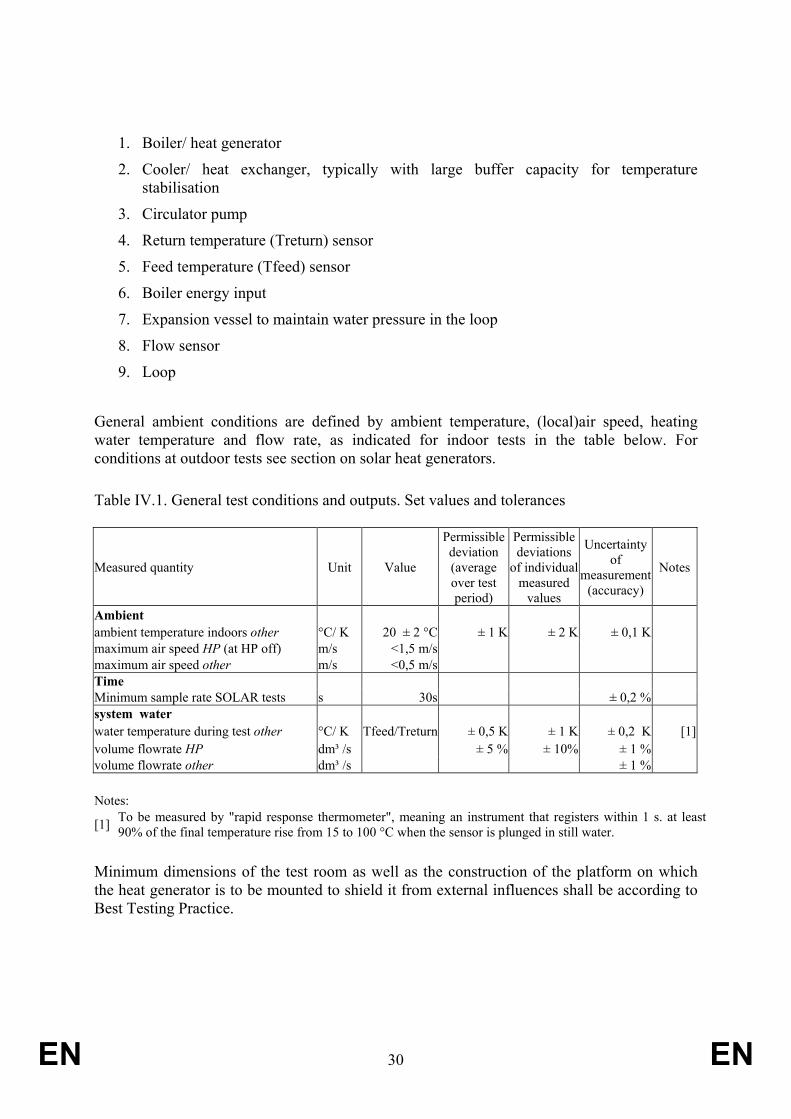
1. Boiler/ heat generator
2. Cooler/ heat exchanger, typically with large buffer capacity for temperature stabilisation
3. Circulator pump
4. Return temperature (Treturn) sensor
5. Feed temperature (Tfeed) sensor
6. Boiler energy input
7. Expansion vessel to maintain water pressure in the loop
8. Flow sensor
9. Loop
General ambient conditions are defined by ambient temperature, (local)air speed, heating water temperature and flow rate, as indicated for indoor tests in the table below. For conditions at outdoor tests see section on solar heat generators. Table IV.1. General test conditions and outputs. Set values and tolerances
Measured quantity Unit Value
Permissible deviation (average over test period)
Permissible deviations
of individual measured
values
Uncertainty of
measurement (accuracy)
Notes
Ambient ambient temperature indoors other °C/ K 20 ± 2 °C ± 1 K ± 2 K ± 0,1 K maximum air speed HP (at HP off) m/s <1,5 m/s maximum air speed other m/s <0,5 m/s Time Minimum sample rate SOLAR tests s 30s ± 0,2 % system water water temperature during test other °C/ K Tfeed/Treturn ± 0,5 K ± 1 K ± 0,2 K [1]volume flowrate HP dm³ /s ± 5 % ± 10% ± 1 % volume flowrate other dm³ /s ± 1 % Notes:
[1] To be measured by "rapid response thermometer", meaning an instrument that registers within 1 s. at least 90% of the final temperature rise from 15 to 100 °C when the sensor is plunged in still water.
Minimum dimensions of the test room as well as the construction of the platform on which the heat generator is to be mounted to shield it from external influences shall be according to Best Testing Practice.

EN 31 EN
TEST PROCEDURE EFFICIENCY AND PERFORMANCE TESTS Tests are performed after thermal equilibrium with the appropriate temperatures, flow rate and energy in- and outputs is reached.
The product of the supplied mass, temperature difference between Treturn and Tfeed and the specific heat capacity of the heating water delivered during the test period is defined as the heat output Qout in kWh. The energy input to the heat generator Qin in kWh is the electric energy consumption during the test and/or the product of the mass/volume of the fossil fuel delivered at reference conditions and its gross calorific value GCV (a.k.a. upper heating value, Hs). Power input Pin and power outputs Pout relate to ratios of energy in- and outputs and the test period. Test point efficiency is defined as the ratio of power output and input.
Possible renewable heat inputs, i.e. solar irradiation and/or ambient heat, shall be supplied to the heat generator at the required test conditions.
In case the prescribed volume flow rate during the test is small and/or the test is conducted in outdoor conditions, e.g. with solar heat generators, the test rig may not necessarily be a loop, provided that the water flowing in the heat generator is supplied at the required Treturn water temperatures.
The circulator pump used during the test may be a separate pump or an integrated pump delivered with the heat generator.
Accuracy and tolerance levels for the energy inputs as defined in document 3 and the underlying document 5 apply.
Efficiency and performance test results are corrected for:
Heat gain by the circulator pump, determined through an additional test or from a default deduction of 55% of the average pump electricity consumption during the test. The pump heating power is to be deducted from the measured power output Pout before calculation of the energy efficiency of a test point.
Deviations from reference conditions for the energy inputs and outputs as defined in document 3.
Depending on the type of heat generator, test conditions are specified by combinations heat generator power input or –output, system feed, return and/or average temperatures and/or flow rates. For renewable energy sources additional requirements as specified below for ambient or solar energy inputs apply.
Depending on the type of heat generator tests shall be performed at between 4 and 6 different test points with specific efficiency values.
EN 32 EN
TEST POINTS AND PRELIMINARY CALCULATIONS
SOLAR COLLECTOR TESTS
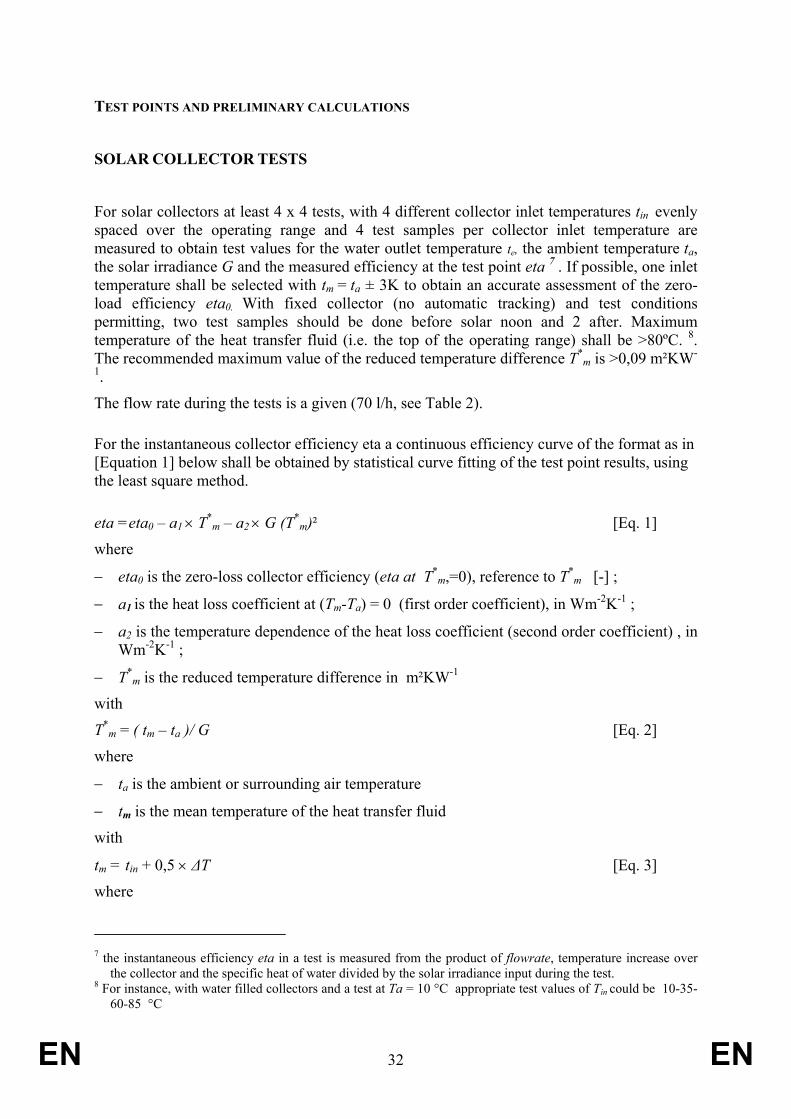
For solar collectors at least 4 x 4 tests, with 4 different collector inlet temperatures tin evenly spaced over the operating range and 4 test samples per collector inlet temperature are measured to obtain test values for the water outlet temperature te, the ambient temperature ta, the solar irradiance G and the measured efficiency at the test point eta 7 . If possible, one inlet temperature shall be selected with tm = ta ± 3K to obtain an accurate assessment of the zero-load efficiency eta0. With fixed collector (no automatic tracking) and test conditions permitting, two test samples should be done before solar noon and 2 after. Maximum temperature of the heat transfer fluid (i.e. the top of the operating range) shall be >80ºC. 8. The recommended maximum value of the reduced temperature difference T*
m is >0,09 m²KW-
1.
The flow rate during the tests is a given (70 l/h, see Table 2). For the instantaneous collector efficiency eta a continuous efficiency curve of the format as in [Equation 1] below shall be obtained by statistical curve fitting of the test point results, using the least square method.
eta =eta0 – a1 × T*m – a2 × G (T*
m)² [Eq. 1]
where
− eta0 is the zero-loss collector efficiency (eta at T*m,=0), reference to T*
m [-] ;
− a1 is the heat loss coefficient at (Tm-Ta) = 0 (first order coefficient), in Wm-2K-1 ;
− a2 is the temperature dependence of the heat loss coefficient (second order coefficient) , in Wm-2K-1 ;
− T*m is the reduced temperature difference in m²KW-1
with
T*m = ( tm – ta )/ G [Eq. 2]
where
− ta is the ambient or surrounding air temperature
− tm is the mean temperature of the heat transfer fluid
with
tm = tin + 0,5 × ∆T [Eq. 3]
where
7 the instantaneous efficiency eta in a test is measured from the product of flowrate, temperature increase over
the collector and the specific heat of water divided by the solar irradiance input during the test. 8 For instance, with water filled collectors and a test at Ta = 10 °C appropriate test values of Tin could be 10-35-
60-85 °C

EN 33 EN
− tin is the collector inlet temperature
− ∆T is temperature difference between fluid outlet and inlet (= te – tin )9.
Unless specified differently, all tests shall be performed according to Best Testing Practice.
INTEGRATED COLLECTOR STORAGE TESTS
In case of an Integrated Collector Storage ICS (e.g. ‘heat pipe’, vacuum-pipes directly coupled to tank, etc.) an alternative test is used, establishing the overall efficiency etasol of the collector+store combination during a 3 day test at maximum heat output, according to Best Testing Practice for this type of heat generator.
AIR SOURCE HEAT PUMPS Test points for air-source heat pumps are given in the table below.
Table IV.2. Test points outdoor air-source HP Test Results Source
temperature low dT (minimum 1 K)
high dT (maximum 20 K)
Note
power output
COP Tout dry bulb
(wet bulb)
Treturn Tsys Tfeed Treturn Tsys Tfeed [1] [2]
kW ºC ºC ºC ºC ºC ºC ºC C Php1 COP1 -7(-8) 49 51 52 41 51 61 [3]
A Php2 COP2 2(1) 40 41 42 33 41 49 B Php3 COP3 7(6) 34 35 36 30 35 40 D Php4 COP4 12(11) 27 28 29 26 28 30 E Php5 COP5 -15(-17) 57 59 61 49 59 69 [4]
cyc Phpcyc COPcyc 12(11) As test point D, but cycling 6 minutes 'on', 24 minutes 'off'
[5]
[1]= Manufacturer to choose between low dT or high dT regime [2]=For low dT regime the tolerance (permissible deviation of average value over testperiod) on Tfeed is 0,5K. For Tsys and Treturn the tolerance is as indicated in table IV.1. For high dT regime the tolerance (permissible deviation of average value over testperiod) on Treturn is 0,5K. For Tsys and Tfeed the tolerance is as indicated in table IV.1. [3]=If binlimit>-7 then COP4=1 and Php4=1 [4]=Test point E only mandatory in case Colder climate is one of the designated climates [5]=Test point 'cyc' and 'D' are used to determine the degradation factor.
9 te is the collector outlet (exit) temperature. Note: tin and te were previously known as Tc,in and Tc,out in the 2001
Edition of EN 12975-2

EN 34 EN
For HP compliance assessment the product shall at least meet the declared power output levels at the given source temperatures and the COP values shall be measured at the declared power output levels.
Testing is differentiated between fixed capacity, staged capacity and variable capacity as defined in document 3.
The following procedure applies for fixed capacity units:
1. Determine the (maximum) efficiency COP and the (maximum) output power Php at steady-state on-mode for each of the 4 or 5 test points. The COP and Php results are inputs in documents 4 and 6.
2. Perform one cyclic test at an outdoor dry bulb temperature of 12 °C. One cycle is 6 minutes in on-mode and 24 minutes in off mode, corresponding to approximately 20% part load conditions. Measure de COP value COPcyc and the average heating power output over the test period Phpcyc .
3. Determine the efficiency degradation between cycling and steady state mode at outdoor temperature 12 °C10: dCOP= COP1 –COPcyc.
4. Determine efficiency loss per kW of output heating power: Cd= dCOP / (Php1 – Pcyc) The Cd-value is to be reported in accordance with document 4 and will be used as an input in document 6.
The following procedure applies for staged capacity units:
1. Determine the heating power output Pc in kW and the electric power consumption Pe in kW at each of the two ‘stages’ of capacity control of the unit. The higher values are denominated Pc1 and Pe1. The lower values are Pc2 and Pe2. For a specific test point with heating power demand (‘load’) Pj, the fractions of Pc1 and Pc2 needed to reach Pj are t1 and t2 respectively, determined by the expressions
t1 = (Pc2-Pj )/( Pc2- Pc1) and t2 = 1 - t1
The aggregated COP value COP” j for a test point in bin j is then COP” j = (t1 *Pc1 + t2 *Pc2)/( t1 *Pe1 + t2 *Pe2)
2. Subsequently a 2,5% correction is applied for the fact that it is staged and not a variable capacity unit (non-linearity), before the final value COP shall be used as a an input in document 4 and document 6.
COP j= 0,975* COP” j
3. If the smallest control step of the unit is higher than the required part load ratio (D and/or C and/or B), the COP at the required part load ratio is determined as for fixed capacity units. The Cd-value is to be reported in accordance with document 4 and will be used as an input in document 6.
10 Can also be at 7 °C outdoor temperature, and using COP2 as a maximum load reference instead of COP1.

EN 35 EN
The following procedure applies for variable capacity units:
1. Perform the tests at the required part load ratios with the corresponding setting of the capacity control of the unit. The COP and Php results are inputs in documents 4 and 6.
2. If the electronic control of the unit does not allow obtaining the required part load ratio, the calculation procedure given for staged capacity units shall be applied.
3. If the smallest setting of the capacity control does not allow reaching one or several part load ratios, the COP at the required part load ratio(s) shall be calculated as for fixed capacity units. The Cd-value is to be reported in accordance with document 4 and will be used as an input in document 6.
OTHER HEAT PUMPS Other types of heat pumps shall be tested at the ambient heat conditions and test points as defined in document 3. The test points are directly used in the model. In addition the degradation factor Cd is determined through a cycling test as for air-source heat pumps.
FOSSIL FUEL The tables below give the test points for preferential (FOS) and non-preferential (FOSB) fossil fuel fired heat generators
Table IV.3. Test points FOS
Name Results Power input
[1] Treturn
[2] Tsys
[3] Tfeed
[3] kW oC oC oC I _eta1 [5] 0,5td*Pinmax 26 28 30 II _eta2 td*Pinmax 30 35 40 III _eta4 Pinmax a) 60 70 80 or b)[4] 45 55 65 IV _eta2hot td*Pinmax a) 60 70 80 or b) [4] 45 55 65 V _eta1hot [5] 0,5td*Pinmax 30 35 40 [1]= If td of the product is larger than 30% then tests are to be performed at a default td value of 30% [2]= Tolerance + 0,5 K [3]= Tolerance as in Table IV.1 [4]= option b) is allowed only if the power output at Pinmax is lower than 1,66Pdesign; if option b) applies for point D then it shall also be used for point E [5]= cycle time (50%'on'+ 50% 'off') is 10 minutes if td of the appliance is >60%, 20 minutes if td is>30% and 30 minutes if td<30%
Table IV.4 . Test points FOSB* Name Results Power input Treturn Tsys** Tfeed**

EN 36 EN
kW oC oC oC Ib _etab1 0,5td*Pinmaxb 30 33-35 36-40 IIb _etab2 td*Pinmaxb 45 55 65 IIIb _etab4 Pinmaxb 60 70 80 *=mandatory for all load profiles
The table IV.5 below gives the input points to be reported for the designated load profiles in accordance with document 4 and with the inputs to be used in document 6.
Table IV.5. Input points FOS an FOSB Heating power output in kW Input Tsys
FOS [1]
Tsys FOSB
[2]
dT (fixed)
[3]
dT (var.)
[4] XS S M L XL XXL 3XL 4XL
eta(b)4 70 70 20 20 5,8 8,8 13,3 20 30 45 66 101 eta(b)3 54 54 12 20 [5] 3,5 5,3 8,0 12 18 27 40 61 eta(b)2 33 45 4 10 1,1 1,6 2,4 3,6 5,4 8 12 18 eta(b)1 28 33 2 4 0,5 0,8 1,2 1,8 2,7 4 6 9
[1]= Applies to preferential fossil-fuel fired heat generator [2]= Applies to non-preferential fossil-fuel fired heat generator
[3]= Temperature difference in K between Tfeed and Treturn with Tsys as middle value, in case of a fixed speed circulator (PMP=3,4) [4]= Temperature difference in K between Tfeed and Treturn with Tsys as middle value, in case of a fixed speed circulator (PMP=1,2,5)
[5]= If manufacturer gives a warranty on the heat exchanger of at least 10 years, this value may be higher, i.e. up to 40 K
In case of a staged capacity unit the efficiency values shall be diminished by 0,025.
The inputs at the input points in Table IV.5 shall be determined through inter-/extrapolation of the test results from the conditions in Tables IV.3 and IV.4 for the designated load profiles. The manufacturer can declare up to 3 designated load profiles in total with those test results.
COGENERATION In case of CHP being part of the product configuration it shall be tested as a preferential fossil fuel fired heat generator FOS, with the heating efficiency values as mentioned in table IV.3 and inter/extrapolated to arrive at the input values as specified in table IV.5. Furthermore, during the test the electric power output is measured and reported as the ratio of electric power output to ‘heat’ (fossil fuel GCV) input. These test results are then used –through inter-/extrapolation—to arrive at the values of _chp4, _chp3, _chp2 and _chp1 at the input points specified in table IV.5.
COMBI-BOILER Testing and calculation method for the assessment of combitrans, to be used as an input for combi-boiler water heating efficiency etawh defined in document 3:

EN 37 EN
1. Determine heat capacity in kWh/K of device cdev and hot water content cwater (through calculation)
2. Make sure boiler and device are at ambient temperature Ta.
3. Fill device with cold water Tcold of 10 °C, immediately run boiler in space heating mode at part load (can be combined with efficiency test in space heating) for 20 minutes (load weighted average time between draw-offs for most tapping patterns M and higher),
4. Stop the boiler for 20 minutes (burner-off) to account for standing losses.
5. Draw-off water from the device until water temperature is again 10 °C. Measured result: Average water temperature of device Tavg, Energy content of drawn off water Qtapped in kWh/draw-off
6. If necessary correct result for heat content of the device at start: Qtappedcor= Qtapped- (Tambient-10)*cdev. Tavg is corrected accordingly.
7. Determine maximum annual capacity Qcapdev in kWh/a (25 draw-offs per day in heating season) Qcapdev= 25*alldays*Qtappedcorr in kWh/d. where alldays is the number of days in the heating season, i.e. 213, 183, 273 days for Average, Warmer and Colder climate respectively.
8. Calculate the 24h average heat store power capacity Pstore=Qcapdev/allhrs
9. From the reference net daily peak energy demand declared water heating load profile Qref in kWhd/d (from document 4, table II.2) calculate the average power demand over the 15h tapping period with Ptap=0,6*Qref/15.
10. From the annual flue gas losses in space heating mode Qflue in kWh/a for the highest declared space heating load profile as determined in document 6, calculate the average loss over the heating season Pflue=Qflue/allhrs.
11. The annual credit for the Passive Flue Heat Recovery Device combitrans in kWh/a is
combitrans= allhrs* MIN(Pstore; Ptap; Pflue)
NOX EMISSIONS NOx emissions are to be tested in accordance with best testing practice. Guidance documents are given in document 7.

EN 38 EN
Document 6 Energy Efficiency Calculation Method
The mathematical model of the space heating boiler in this document (hereafter ‘the model’) calculates the specific energy efficiency etas from the input data given in document 4, Product Information requirements, Table II.4a in accordance with the definitions in document 3 and the testing methods and preliminary calculations in document 5.
The model is built top-down, with the most aggregated parameters first, followed by the parameters from which the aggregated parameters are built.
The model is divided in three parts:
a definition section (eq. 1-14), giving the general definitions of efficiency, total energy consumption as well as the equations for informative issues as already defined in documents 3 and 4.
a heat balance calculation (eq. 15-93), subdivided in
a heat demand section (eq. 15-30), dealing with the net space heating demand Lh (Eq. 15) that follows from the choice of the load profile and the so-called system losses Lsys (Eq. 16-30) that in part depend on the characteristics of the boiler and in part on other installation characteristics that are treated as constants. The system losses are fluctuation losses (Eq. 17-19), stratification losses (Eq. 20-21), distribution losses (Eq. 22-23), losses of buffers (Eq. 24-25), the losses from not optimally utilizing the night-setback potential Qtim (Eq. 25-28) and finally losses or gains related to controls (Eq. 29-30).
a heat supply section (Eq. 30-93), calculating the contribution of each of the possible heat generator types SOL (eq. 32-57), HP (eq. 58-86), ELBU(eq. 87), FOS (eq. 88-90) and FOSB (eq. 91-93) in terms of their annual heating energy output ‘L’in kWh/a. For FOS and FOSB this entails a simple capacity calculation, but SOL-output depends on the solar irradiance during the heating season –calculated with monthly inputs—and air-source HP outputs depends on the outdoor air (source) temperature, calculated with the bin-method (see document 3).
a primary energy loss accounting (eq. 94-183), subdivided in
heat generator losses (eq. 94- 164), usually –except for SOL and ELBU where a simple annual multiplier is sufficient—calculated per outdoor temperature bin, and using the data inputs from tests as defined in document 5;
auxiliary energy losses (eq. 164-175), calculated on an annual basis and possible CHP gain from electric power production during the heat generating processes (eq. 176-183).
For the most part the model is a simple case of energy accounting. The accounting is comprehensive, also featuring parameters that might be redundant but serve transparency and a future purpose in model maintenance, but uses mostly simple linear equations.
A special feature is the use of the bin-method -as described in document 3- and the fact that the equations for inter- (and extra)polation between data inputs from the tests are explicitly part of the model, e.g. in eq. 65-70 (HP), eq. 118-132 (FOS) and eq. 178-183 (CHP). This may seem unnecessarily complex, because a simple instruction to interpolate between test point values could fully define any intermediate points. But it allows for more robust

EN 39 EN
modelling -with also a check on the overall contribution of a testing point to the end-result- and it allows the relatively simple incorporation of the modelling of the system buffer BUF with FOS and CHP.
Another feature is the transition of the energy calculation from the monthly method for SOL to the bin-method for HP and any of the following heat generators in eq. 71-80. This conversion the calculated annual heat output from SOL (Lsol) according to the monthly method is redistributed over the temperature bins, starting at the hour-bins with the highest temperature and ending when the accumulated value of Lsol is exhausted. The remaining heat demand profile is then ‘offered’ to HP and the following heat generators, in the order as described in document 3.
NOMENCLATURE Parameters are listed as they are used, i.e. in the heat balance (Table V.1) and in the primary energy loss accounting (Table V.2). Table V.3 gives the main test and data input names.
Table V.1. Nomenclature: Heat Balance HEAT (kWh/a) demand total 0 space heating demand Lh 0 system losses Lsys 0 of which fluctuation losses Qfluct 0 stratification losses
Qstrat 0 distribution losses Qdistr 0 buffer losses Qbuf 0 timer losses Qtim 0 supply total 0 generator useful heat Lgen 0 of which solar heat supply Lsol 0 heat pump heat supply Lhp 0 electric back-up heat supply Lelbu 0 fossil fuel fired preferential generator heat supply
Lfos 0
non-preferential fossil fuel fired generator heat supply
Lfosb
0
Balance: Lh+Lsys=Lgen
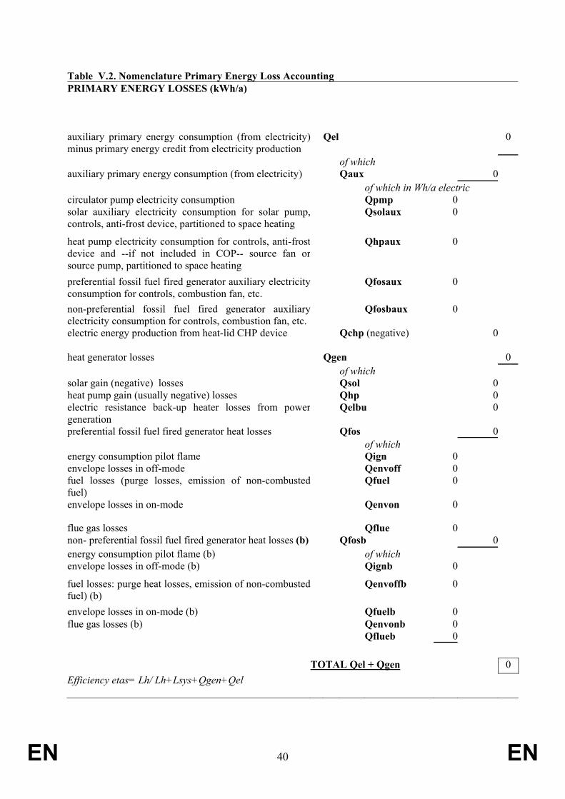
EN 40 EN
Table V.2. Nomenclature Primary Energy Loss Accounting PRIMARY ENERGY LOSSES (kWh/a)
auxiliary primary energy consumption (from electricity)minus primary energy credit from electricity production
Qel 0
of which auxiliary primary energy consumption (from electricity) Qaux 0 of which in Wh/a electric circulator pump electricity consumption Qpmp 0 solar auxiliary electricity consumption for solar pump,controls, anti-frost device, partitioned to space heating
Qsolaux 0
heat pump electricity consumption for controls, anti-frost device and --if not included in COP-- source fan or source pump, partitioned to space heating
Qhpaux 0
preferential fossil fuel fired generator auxiliary electricityconsumption for controls, combustion fan, etc.
Qfosaux 0
non-preferential fossil fuel fired generator auxiliaryelectricity consumption for controls, combustion fan, etc.
Qfosbaux 0
electric energy production from heat-lid CHP device Qchp (negative) 0 heat generator losses Qgen 0 of which solar gain (negative) losses Qsol 0 heat pump gain (usually negative) losses Qhp 0 electric resistance back-up heater losses from powergeneration
Qelbu 0
preferential fossil fuel fired generator heat losses Qfos 0 of which energy consumption pilot flame Qign 0 envelope losses in off-mode Qenvoff 0 fuel losses (purge losses, emission of non-combusted fuel)
Qfuel 0
envelope losses in on-mode Qenvon 0
flue gas losses Qflue 0 non- preferential fossil fuel fired generator heat losses (b) Qfosb 0 energy consumption pilot flame (b) of which envelope losses in off-mode (b) Qignb 0
fuel losses: purge heat losses, emission of non-combusted fuel) (b)
Qenvoffb 0
envelope losses in on-mode (b) Qfuelb 0 flue gas losses (b) Qenvonb 0 Qflueb 0 TOTAL Qel + Qgen 0 Efficiency etas= Lh/ Lh+Lsys+Qgen+Qel

EN 41 EN
Table V.3. Nomenclature energy, power, efficiency and time for heat and power generators heat generator (Boolean) SOL HP ELBU FOS FOSB CHP Energy in kWh/a instantaneous heat input (GCV of fuel) Qin Qinb
primary energy loss total or per period/bin Qsol Qhp Qelbu Qfos Qfosb
useful output Lsol Lhp Lelbu Lfos Lfosb Power in kW maximum heat input in kWh/h upperheating value of fuel (GCV) Pinmax Pinmaxb
heat demand remaining after SOL, HP,FOS Prs Prh Prf
Efficiency (output/input) test points
cold climate only: -15 ºC test point COP5 efficiency at maximum heat demand(load) COP4
efficiency at intermediate load COP3 _eta4 _etab4 _chp4
efficiency at low load (or minimumsteady state for FOS) COP2 _eta2 _etab2 _chp2
efficiency at very low load (or 50%minimum steady state for FOS)
eta_0,a_1, a_2, IAM etasol
COP1
prim-energy
_eta1 _etab1 _chp1
extra test point cycling COPcyc extra test point multiple load profiles 1 _eta2hot _chp2hot extra test point multiple load profiles 2 _eta1hot _chp1hot Efficiency (output/input) input points
arrays of powers ( input points from tests) Php Pfos Pfosb chp
COP5 cold climate only: -15 ºC
(Php5) eta4 etab4 efficiency (power) at maximum heat
input COP4 (Php4) (Pfos4) (Pfosb4) chp4
eta3 etab3 efficiency (power) at design conditions COP3 (Php3) (Pfos3) (Pfosb3) chp3
eta2 etab2 efficiency (power) at minimum heat input(steady state) COP2
(Php2) (Pfos2) (Pfosb2) chp2
eta1 etab1 efficiency at very low load (or 50%minimum steady state for FOS) COP1
(Php1) (Pfos1) (Pfosb1)
chp1
eta4 etab4 zero load 'efficiency' COP0 (Php0) (Pfos4) (Pfosb4) chp0
Other multipliers interpolation w b bb b hours in on mode solhrs hphrs foshrs fosbhrs foshrs hours in heating season allhrs
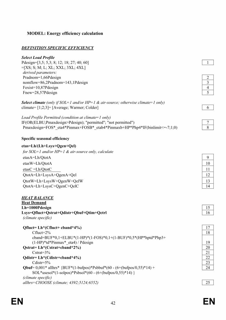
EN 42 EN
MODEL: Energy efficiency calculation
DEFINITION SPECIFIC EFFICIENCY Select Load Profile Pdesign=[3,5; 5,3; 8; 12; 18; 27; 40; 60] 1 =[XS; S; M; L; XL; XXL; 3XL; 4XL] derived parameters: Pradnom=1,66Pdesign 2 nomflow=86,2Pradnom=143,1Pdesign 3 Fexist=10,87Pdesign 4 Fnew=28,57Pdesign 5 Select climate (only if SOL=1 and/or HP=1 & air-source; otherwise climate=1 only) climate= [1;2;3]= [Average; Warmer; Colder] 6 Load Profile Permitted (condition at climate=1 only) IF(OR(ELBU;Pmaxdesign>Pdesign); "permitted"; "not permitted") 7 Pmaxdesign=FOS*_eta4*Pinmax+FOSB*_etab4*Pinmaxb+HP*Php4*IF(binlimit<=-7;1;0) 8 Specific seasonal efficiency
etas=Lh/(Lh+Lsys+Qgen+Qel) for SOL=1 and/or HP=1 & air-source only, calculate etasA=Lh/QtotA 9 etasW=Lh/QtotA 10 etasC =Lh/QtotC 11 QtotA=Lh+LsysA+QgenA+Qel 12 QtotW=Lh+LsysW+QgenW+QelW 13 QtotA=Lh+LsysC+QgenC+QelC 14
HEAT BALANCE Heat Demand Lh=1000Pdesign 15 Lsys=Qfluct+Qstrat+Qdistr+Qbuf+Qtim+Qctrl 16 (climate specific) Qfluct= Lh*(Cfluct+ cband*4%) 17 Cfluct=2% 18
cband=BUF*0,1+ELBU*(1-HP)*(1-FOS)*0,1+(1-BUF)*0,5*(HP*hptd*Php3+ (1-HP)*td*Pinmax*_eta4) / Pdesign 19
Qstrat= Lh*(Cstrat+cband*2%) 20 Cstrat=3% 21 Qdistr= Lh*(Cdistr+cband*4%) 22 Cdistr=5% 23 Qbuf= 0,001* allhrs* {BUF*(1-bufpos)*Psbbuf*(60 - (6+(bufpos/0,55)*14) + 24 SOL*usesol*(1-solpos)*Psbsol*(60 - (6+(bufpos/0,55)*14) } (climate specific) allhrs=CHOOSE (climate; 4392;5124;6552) 25
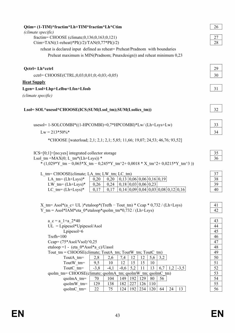
EN 43 EN
Qtim= (1-TIM)*fractim*Lh+TIM*fractim*Lh*Ctim 26 (climate specific) fractim= CHOOSE (climate;0,136;0,163;0,121) 27 Ctim=TAN((1-reheat)*PI()/2)/TAN(0,77*PI()/2) 28 reheat is declared input defined as reheat= Preheat/Pradnom with boundaries Preheat maximum is MIN(Pradnom; Pmaxdesign)) and reheat minimum 0,23 Qctrl= Lh*cctrl 29 cctrl= CHOOSE(CTRL;0,03;0,01;0;-0,03;-0,05) 30 Heat Supply Lgen= Lsol+Lhp+Lelbu+Lfos+Lfosb 31 (climate specific)
Lsol= SOL*usesol*CHOOSE(ICS;SUM(Lsol_tm);SUM(Lsolics_tm)) 32
usesol= 1-SOLCOMBI*((1-HPCOMBI)+0,7*HPCOMBI)*Lw/ (Lh+Lsys+Lw) 33
Lw = 213*50%* 34
*CHOOSE [waterload; 2,1; 2,1; 2,1; 5,85; 11,66; 19,07; 24,53; 46,76; 93,52]
ICS=[0;1]=[no;yes] integrated collector storage 35 Lsol_tm =MAX(0; L_tm*(Lh+Lsys)) * 36 * (1,029*Y_tm − 0,065*X_tm − 0,245*Y_tm^2+ 0,0018 * X_tm^2+ 0,0215*Y_tm^3 )) L_tm= CHOOSE(climate; LA_tm; LW_tm; LC_tm) 37 LA_tm= (Lh+Lsys)* 0,20 0,20 0,13 0,06 0,06 0,16 0,19 38 LW_tm= (Lh+Lsys)* 0,26 0,24 0,18 0,03 0,06 0,23 39 LC_tm= (Lh+Lsys)* 0,17 0,17 0,14 0,09 0,04 0,03 0,08 0,12 0,16 40 X_tm= Asol*(a_c+ UL )*etaloop*(Trefh − Tout_tm) * Ccap * 0,732 / (Lh+Lsys) 41 Y_tm = Asol*IAM*eta_0*etaloop*qsolm_tm*0,732 / (Lh+Lsys) 42 a_c = a_1+a_2*40 43 UL = Lpipesol*Upipesol/Asol 44 Lpipesol=6 45 Trefh=100 46 Ccap= (75*Asol/Vsol)^0,25 47 etaloop =1 - (eta_0*Asol*a_c)/Uasol 48 Tout_tm = CHOOSE(climate; ToutA_tm; ToutW_tm; ToutC_tm) 49 ToutA_tm= 2,8 2,6 7,4 12 12 5,6 3,2 50 ToutW_tm= 9,5 10 12 15 15 10 51 ToutC_tm= -3,8 -4,1 -0,6 5,2 11 13 6,7 1,2 -3,5 52 qsolm_tm= CHOOSE(climate; qsolmA_tm; qsolmW_tm; qsolmC_tm) 53 qsolmA_tm= 70 104 149 192 129 80 56 54 qsolmW_tm= 129 138 182 227 126 110 55 qsolmC_tm= 22 75 124 192 234 120 64 24 13 56

EN 44 EN
In case of ICS/thermosiphon Lsolics_tm= MIN(L_tm*(Lh+Lsys); 0,732*Asol*etasol*qsolm_tm) 57 etasol is ICS efficiency (solar input/ useful heat output) from best testing practice qsoltest per m2 Asol is average global solar irradiation during full test period (minimum 3 days) Lhp= HP*usehp*SUM(Lhp_tp) 58 usehp=1- HPCOMBI*((1-SOLCOMBI)+0,3*SOLCOMBI)*Lw/ (Lh+Lsys+Lw) 59 Lhp_tp= HP*Pout_tp*hphrs_tp 60 hphrs_tp=HP*IF(Pouthp_tp>0;hr_tp;0) 61 Pouthp_tp=HP*MIN(Poutmax_tp; Prs_tp) 62 Poutmaxhp_tp= binlimit_tp*Pmaxhp 63 binlimit_tp=IF(binlimit<=Tout_tp;1;0) 64 Pmaxhp_tp==Php1*w1_tp+Php2*w2_tp+Php3*w3_tp+Php4*w4_tp 65 Php1, Php2, Php3, Php4 are power outputs at test points tst tst is array of Tout temperature of testbins. Tst=[tst1;tst2;tst3;tst;4] with condition tst1>tst2>tst3>tst4 66 Pmaxhp_tp is inter/extrapolation between these points, linear with Tout using the following multipliers: w1_tp=IF(Tout_tp>=tst1;1+(Tout_tp-tst1)/(tst1-tst2); 67 IF(AND(Tout_tp>tst2;Tout_tp<tst1);1-(Tout_tp-tst1)/(tst2-tst1);0)) w2_tp=IF(AND(Tout_tp<tst1;Tout_tp>=tst2);(Tout_tp-tst1)/(tst2-tst1); 68 IF(AND(Tout_tp>tst3;Tout_tp<tst2);1-(Tout_tp-tst2)/(tst3-tst2); IF(Tout_tp>tst1;(Tout_tp-tst1)/(tst2-tst1);0))) w3_tp=IF(AND(Tout_tp<tst2;Tout_tp>=tst3);(Tout_tp-tst2)/(tst3-tst2); 69 IF(AND(Tout_tp>tst4;Tout_tp<tst3);1-(Tout_tp-tst3)/(tst4-tst3); IF(Tout_tp<4;-(Tout_tp-tst4)/(tst4-tst3);0))) w4_tp=IF(AND(Tout_tp<tst3;Tout_tp>=tst4);(Tout_tp-tst3)/(tst4-tst3); 70 IF(AND(Tout_tp<tst4);1+(Tout_tp-tst4)/(tst4-tst3);0)) in case of Cold climate eq. 69 and eq. 70 change; see endnote for all bins,except 'night'bin Prs_tp=IF(hr_tp>0;(Lhsys_tp-Lsol_tp)/hr_tp;0) 71 Lhsys_tp= (Lh+Lsys)*fracn_tp 72 fracn_tp=frac_tp/SUM(frac_tp) 73 frac_tp=(1-TIM)*fracs_tp+TIM*fracd_tp 74 fracs_tp=CHOOSE(climate; fracsA_tp; fracsW_tp; fracsC_tp) 75 fracd_tp=CHOOSE(climate; fracdA_tp; fracdW_tp; fracdC_tp) 76 VALUES FROM TABLE I.1 Lsol_tp=Lhsys_tp*IF(fracac_tp<solfrac;1; 77 IF(fracac_tp-frac_tp<solfrac;(solfrac-fracac_tp-frac_tp)/frac_tp;0) 78 solfrac=Lsol/(Lh+Lsys) 79 fracac=SUM(fracn_0:fracn_tp) 80

EN 45 EN
hr_tp=(1-TIM)*hrs_tp+TIM*hrd_tp 81 hrs_tp=CHOOSE(climate; hrsA_tp; hrsW_tp; hrsC_tp) 82 hrd_tp=CHOOSE(climate; hrdA_tp; hrdW_tp; hrdC_tp) 83 VALUES FROM TABLE I.1 for 'night' bin: depends on TIM ; all expressions are to be multiplied with TIM following expressions are different from above Prs_tp(night)=TIM*reheat*Pradnom 84 frac_tp(night)=TIM*(0,01*fracd_tp(night)+Ctim*0,136) 85 substitute 0,136 with 0,161/0,121 in case of Warmer/Colder climate 86 hr_tp(night)=IF(Prs_tp>0;TIM*Lhsys_tp/Prs_tp;0) Note that the ‘night’ outdoor temperatures are +1,+6, 0 ºC for A, W, C climates Lelbu=ELBU*(Lh+Lsys-SOL*Lsol-HP*Lhp) 87 Lfos=SUM (Lfos_tp) 88 Lfos_tp= (1-ELBU)*FOS*IF(Prh_tp>_eta4*Pinmax;_eta4*Pinmax*hr_tp; Prh_tp*hr_tp) 89 Prh_tp= Prs_tp-Pouthp_tp 90 Lfosb=(1-ELBU)*FOSB*(Lh+Lsys-SOL*Lsol-HP*Lhp-FOS*Lfos) 91 Lfosb_tp=Prf_tp*hr_tp 92 Prf_tp=Prh_tp -IF(hr_tp>0;Lfos_tp/hr_tp;0) 93 PRIMARY ENERGY LOSS ACCOUNTING Qgen=Qsol+Qhp+Qelbu+Qfos+Qfosb 94 Qsol= SOL*- Lsol 95 Qhp= HP*SUM (Qhp_tp)-Lhp 96 Qhp_tp=primenergyfac*Lhp_tp/COP_tp 97 COP_tp=COP1*w1_tp+COP2*w2_tp+COP3*w3_tp+COP4*w4_tp 98
- (Pouthp_tp-Pmaxhp_tp)*Cd_tp COP1, COP2, COP3, COP4 are steady state COP-values at test points;
COP_tp is inter/extrapolation between these points, linear with Tout minus degradation factor Cd for cycling Cd is measured at Php1=Pmax and COP1=COPmax Cd=(COPmax- COPcyc)/ (Pmax-Pcyc) COPcyc, Pcyc are measured at Php1/COP1 conditions but with 6 minutes on/ 24 minutes off cycling
Cd is applied only if the part load is lower than the turndown ratio Cd_tp=IF(AND(Pouthp_tp>0; Pmaxhp_tp>0); IF(Pouthp_tp/Pmaxhp_tp<HPtd; Cd;0); 0) 99
primenergyfac=IF(HPELEC;2,5;1) 100
HPELECis declared input, with HPELEC=1=electric andHPELEC=0=fossil
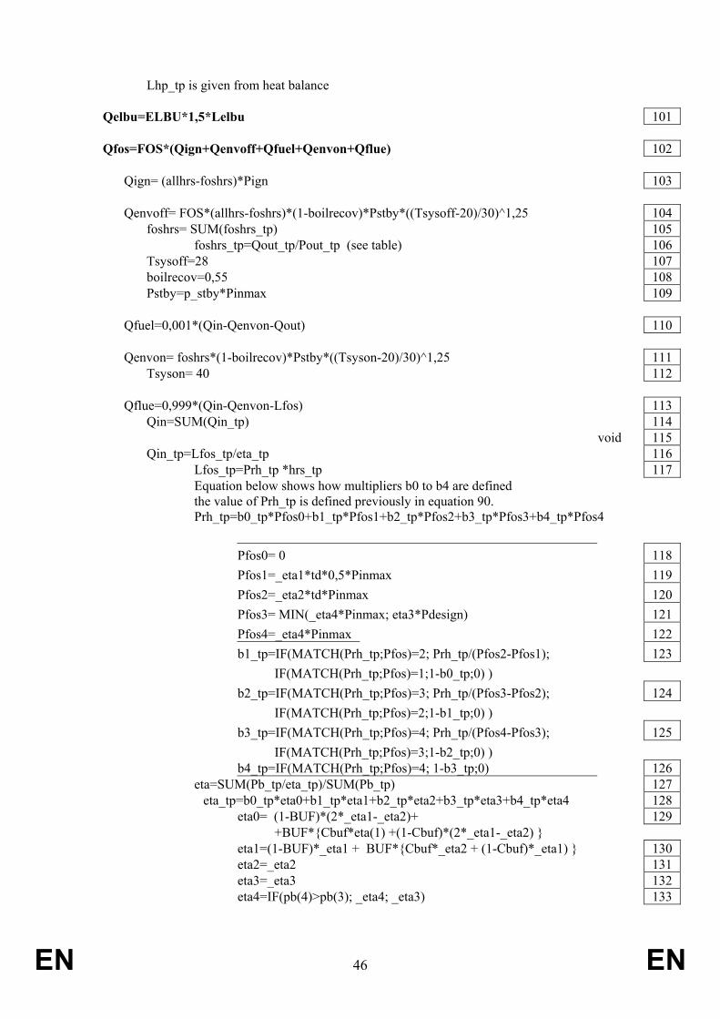
EN 46 EN
Lhp_tp is given from heat balance Qelbu=ELBU*1,5*Lelbu 101 Qfos=FOS*(Qign+Qenvoff+Qfuel+Qenvon+Qflue) 102 Qign= (allhrs-foshrs)*Pign 103 Qenvoff= FOS*(allhrs-foshrs)*(1-boilrecov)*Pstby*((Tsysoff-20)/30)^1,25 104 foshrs= SUM(foshrs_tp) 105 foshrs_tp=Qout_tp/Pout_tp (see table) 106 Tsysoff=28 107 boilrecov=0,55 108 Pstby=p_stby*Pinmax 109 Qfuel=0,001*(Qin-Qenvon-Qout) 110 Qenvon= foshrs*(1-boilrecov)*Pstby*((Tsyson-20)/30)^1,25 111 Tsyson= 40 112 Qflue=0,999*(Qin-Qenvon-Lfos) 113 Qin=SUM(Qin_tp) 114 void 115 Qin_tp=Lfos_tp/eta_tp 116 Lfos_tp=Prh_tp *hrs_tp 117 Equation below shows how multipliers b0 to b4 are defined the value of Prh_tp is defined previously in equation 90. Prh_tp=b0_tp*Pfos0+b1_tp*Pfos1+b2_tp*Pfos2+b3_tp*Pfos3+b4_tp*Pfos4 Pfos0= 0 118 Pfos1=_eta1*td*0,5*Pinmax 119 Pfos2=_eta2*td*Pinmax 120 Pfos3= MIN(_eta4*Pinmax; eta3*Pdesign) 121 Pfos4=_eta4*Pinmax 122 b1_tp=IF(MATCH(Prh_tp;Pfos)=2; Prh_tp/(Pfos2-Pfos1); 123 IF(MATCH(Prh_tp;Pfos)=1;1-b0_tp;0) ) b2_tp=IF(MATCH(Prh_tp;Pfos)=3; Prh_tp/(Pfos3-Pfos2); 124 IF(MATCH(Prh_tp;Pfos)=2;1-b1_tp;0) ) b3_tp=IF(MATCH(Prh_tp;Pfos)=4; Prh_tp/(Pfos4-Pfos3); 125 IF(MATCH(Prh_tp;Pfos)=3;1-b2_tp;0) ) b4_tp=IF(MATCH(Prh_tp;Pfos)=4; 1-b3_tp;0) 126 eta=SUM(Pb_tp/eta_tp)/SUM(Pb_tp) 127 eta_tp=b0_tp*eta0+b1_tp*eta1+b2_tp*eta2+b3_tp*eta3+b4_tp*eta4 128 eta0= (1-BUF)*(2*_eta1-_eta2)+ 129 +BUF*{Cbuf*eta(1) +(1-Cbuf)*(2*_eta1-_eta2) } eta1=(1-BUF)*_eta1 + BUF*{Cbuf*_eta2 + (1-Cbuf)*_eta1) } 130 eta2=_eta2 131 eta3=_eta3 132 eta4=IF(pb(4)>pb(3); _eta4; _eta3) 133

EN 47 EN
Cbuf=MIN(1;MAX(0; Vbuf-9Pdesign)/41Pdesign)) 134 Qfosb=FOSB*(Qignb+Qenvoffb+Qfuelb+Qenvonb+Qflueb) 135 Qignb= FOSB*(allhrs-onhrsb)*Pignb 136 Qenvoffb=FOSB*(allhrs-fosbhrs)*(1-boilrecov)*Pstbyb*((Tsysoffb-20)/30)^1,25 137 fosbhrs= SUM(fosbhrs_tp)= Qoutb_tp/Poutb_tp 138 Tsysoffb=28 139 Qfuelb=FOSB*0,001*(Qinb-Qenvonb) 140 Qenvonb=FOSB*fosbhrs*(1-boilrecov)*Pstbyb*((Tsysonb-20)/30)^1,25 141 Tsysonb= 60 142 Qflueb= 0,999*(Qinb-Qenvonb-Lfosb) 143 Qinb= SUM(Qinb_tp) 144 Qinb_tp=Lfosb_tp/etab/tp 145 Lfosb_tp=Prf_tp*hrs_tp 146 Equation below shows how multipliers bb0 to bb4 are defined the value of Prf_tp is defined previously in equation 93 Prf_tp=bb0_tp*Pfosb0+bb1_tp*Pfosb1++bb2_tp*Pfosb2+bb3_tp*Pfosb3+bb4_tp*Pfosb4 Pfosb0= 0 147 Pfosb1=_etab1*tdb*0,5*Pinmaxb 148 Pfosb2=_etab2*tdb*Pinmaxb 149 Pfosb3= MAX(_eta4*Pradnom;Pdesign) 150 Pfosb4=_eta4b*Pinmaxb 151 Pfosb is array [Pfosb0:Pfosb4] 152 bb0_tp=IF(MATCH(Prf_tp; Pfosb)=1; Prf_tp/(Pfosb1-Pfosb0);0) 153 bb1_tp=IF(MATCH(Prf_tp; Pfosb)=2; Prf_tp/(Pfosb2-Pfosb1); 154 IF(MATCH(Prf_tp; Pfosb)=1;1-bb0_tp;0) ) bb2_tp=IF(MATCH(Prf_tp; Pfosb)=3; Prf_tp/(Pfosb3-Pfosb2); 155 IF(MATCH(Prf_tp; Pfosb)=2;1-bb1_tp;0) ) bb3_tp=IF(MATCH(Prf_tp; Pfosb)=4; Prf_tp/(Pfosb4-Pfosb3); 156 IF(MATCH(Prf_tp; Pfosb)=3;1-bb2_tp;0) ) bb4_tp=IF(MATCH(Prf_tp; Pfosb)=4; 1-bb3_tp;0) 157 etab=SUM(Pbb_tp/etab_tp)/ SUM(Pbb_tp) 158 etab_tp=bb0*etab0+bb1*etab1+bb2*etab2+bb3*etab3+bb4*etab4 159 etab0= 2*_etab1-_etab2 160 etab1= _etab1 161 etab2= _etab2 162 etab3= _etab3 163 etab4= IF(Pfosb4>Pfosb3; _etab4; _etab3) 164 Qel=Qaux-CHP*Qchp 165

EN 48 EN
Qaux= Qpmp+(primenergy-auxrecov)*{Qsolaux+Qhpaux+Qfosaux+Qfosbaux} 166 Qpmp= cpmp*tpump*Lh 167 tpump=CHOOSE(tpmp;(MAX(hponhrs;onhrs)+200)/allhrs; 168 (allhrs-0,33*(allhrs-MAX(hponhrs;onhrs)))/allhrs; 1) cpmp=CHOOSE(PMP;0,02; 0,025; 0,04; 0,05; 0,06) 169 Qsolaux= SOL*0,001*usesol*(solhrs*solaux+(allhrs-solhrs)*solsb) 170 solhrs=0,163*allhrs 171 Qhpaux=HP*0,001*usehp*(onhrshp*hpaux+(allhrs-onhrshp)*hpsb) 172 Qfosaux= FOS*0,001*(foshrs*fosaux+(allhrs-foshrs)*fossb) 173 fosaux=0,5*(elmax+elmin) 174 Qfosbaux= fosbhrs*fosaux+(allhrs-fosbhrs)*fosbsb 175 fosbaux=0,5*(elmaxb+elminb) 176 Qchp= CHP*primenergy*SUM (Qchp_tp) 177 Qchp_tp=foshrs_tp*Pchp_tp 178 Pchp_tp= b1_tp*chp1+b2_tp*chp2+b3_tp*chp3+b4_tp*chp4 179 chp1= (1-BUF)*_chp1*0,5*td*Pinmax+ BUF*( CBuf*_chp2*0,5*td*Pinmax 180 + (1-Cbuf)*_chp1*0,5*td*Pinmax) chp2= _chp2*td*Pinmax 181 chp3= IF(_chp4*Pinmax>Pdesign;_chp3*(Pdesign/_eta3);_chp4*Pinmax) 182 chp4= _chp4*Pinmax 183
Endnote:
In case of a cold climate COP5 is added as a new test point and equations 69, 70 and 98 change as follows:
Eq. 65 Pmaxhp_tp=Php1*w1C_tp+Php2*w2C_tp+Php3*w3C_tp+Php4*w4C_tp+Php5*w5C_tp Eq. 69
w3C_tp=IF(AND(ToutC_tp<tst2;ToutC_tp>=tst3);(ToutC_tp-tst2)/(tst3-tst2); IF(AND(ToutC_tp>tst4;ToutC_tp<tst3);1-(ToutC_tp-tst3)/(tst4-tst3); IF(ToutC_tp<4;-(ToutC_tp-tst4)/(tst4-tst3);0)))
Eq. 70
w4C_tp=IF(AND(ToutC_tp<tst3;ToutC_tp>=tst4);(ToutC_tp-tst3)/(tst4-tst3); IF(ToutC_tp<tst4;1-(ToutC_tp-tst4)/(tst5-tst4);0))
add Eq. 70a
w5C_tp=IF(AND(ToutC_tp<tst4;ToutC_tp>=tst5);(ToutC_tp-tst4)/(tst5-tst4); IF(ToutC_tp<tst5;1+(ToutC_tp-tst5)/(tst5-tst4);0))
Eq. 98
COP_tp=(COP1*w1C_tp+COP2*w2C_tp+COP3*w3C_tp+COP4*w4C_tp+COP5*w5C_tp) - (Pouthp_tp-Pmaxhp_tp)*Cd_tp

EN 49 EN
Document 7 Verification procedure for market surveillance purposes
Verification procedure tolerances for compliance assessment of the final outcome are for:
declared efficiency etas values 5%.
declared heating power output 5% and
NOx emissions 10%
For the purposes of checking conformity with the requirements, the authorities of the Member States shall use the procedure set out in Annex II and reliable, accurate and reproducible measurement procedures, which take into account the generally recognised state of the art measurement methods, including methods set in documents the reference numbers of which have been published for that purpose in the Official Journal of the European Union.
Relevant documents:
General and relating to heat demand (in numerical order)
EN 442-2:1996; Radiators and convectors - Part 2: Test methods and rating
EN 12803:2006 Heating systems in buildings - Method for calculation of the design heat load
EN ISO 13790:2008. Thermal performance of buildings - Calculation of energy use for space heating and cooling. [replaces EN 832:1998]
EN 15232:2007; Energy performance of buildings - Impact of Building Automation, Controls and Building Management
EN 15316-2-1:2007, Heating systems in buildings - Method for calculation of system energy requirements and system efficiencies - Part 2 ( Space heating emission and distribution systems), 10.2005
EN 15316-2-3:2007, Heating systems in buildings - Method for calculation of system energy requirements and system efficiencies - Part 2-3: Space heating distribution systems, 10.2005
EN 15316-4:2007, Heating systems in buildings - Method for calculation of system energy requirements and system efficiencies - Part 4: Space heating generation systems; [parts 1 to 4 on combustion, heat pumps, solar, CHP respectively]
EN 15377:2008 Heating systems in buildings - Design of embedded water based surface heating and cooling systems – (Part 1: Determination of the design heating and cooling capacity; Part 2: Design, dimensioning and installation; Part 3: Optimizing for use of renewable energy sources)
Relating to solar heat generators SOL (in numerical order)
ISO 9459-2; 1995. Solar heating - Domestic water heating Systems - Part 2: Outdoor test methods for System Performance characterization and yearly Performance prediction of solar-only Systems

EN 50 EN
EN 15316-4-3; 2007. Heating systems in buildings - Method for calculation of system energy requirements and system efficiencies - Part 4-3: Space heating generation systems, thermal solar systems. EN 12975-1:2006. THERMAL SOLAR SYSTEMS AND COMPONENTS. SOLAR COLLECTORS. PART 1: GENERAL REQUIREMENTS. EN 12975-2; 2006. Thermal solar systems and components – Solar collectors - Part 2: Test methods EN 12976-1:2000. Thermal solar systems and components - Factory made systems –. Part 1: General requirements. EN 12976-2; 2006. Thermal solar systems and components - Factory made systems - Part 2: Test methodsISO 9459-5; 2007. Solar heating - Domestic water heating Systems - Part 5: System Performance Characterization by Means of Whole System Tests and Computer Simulation ENV 12977-2; 2001. Thermal Solar Systems – Custom built systems—Part 2: Test Methods EN 12977-3; 2008. Thermal Solar Systems – Custom built systems—Part 3: Performance test methods for solar water heater stores.
Relating to heat pumps HP (in numerical order)
EN 14511:2004, Air conditioners, liquid chilling packages and heat pumps with electrically driven compressors for space heating and cooling;
ISO 5151-2005, Non-ducted air conditioners and heat pumps – Testing and rating for performance;
EN 62301:2005. Household Electrical Appliances: Measurement of standby power.
EN 12102 :2008. Air conditioners, liquid chilling packages, heat pumps and dehumidifiers with electrically driven compressors for space heating and cooling - Measurement of airborne noise - Determination of the sound power.
Relating to fossil-fuel fired heat generators FOS, FOSB (in numerical order)
EN 267:1999. Forced draught oil burners - Definitions, requirements, testing, marking. [to be replaced by prEN 267:2005]
EN 297:1994. Gas-fired central heating boilers - Type B11 and B11BS boilers fitted with atmospheric burners of nominal heat input not exceeding 70 kW.
EN 303-1:1999. Heating boilers - Part 1: Heating boilers with forced draught burners - Terminology, general requirements, testing and marking.
EN 303-2:1998 en. Heating boilers - Part 2: Heating boilers with forced draught burners - Special requirements for boilers with atomizing oil burners.
EN 303-3:1998. Heating boilers - Part 3: Gas-fired central heating boilers - Assembly comprising a boiler body and a forced draught burner.
EN 303-4:1999. Heating boilers - Part 4: Heating boilers with forced draught burners - Special requirements for boilers with forced draught oil burners with outputs up to 70 kW and

EN 51 EN
a maximum operating pressure of 3 bar - Terminology, special requirements, testing and marking.
EN 303-6:2000 en. Heating boilers - Part 6: Heating boilers with forced draught burners - Specific requirements for the domestic hot water operation of combination boilers with atomizing oil burners of nominal heat input not exceeding 70 kW.
PrEN 303-7 dec. 2003. Heating boilers - Part 7: Gas-fired central heating boilers equipped with a forced draught burner of nominal heat output not exceeding 1000 kW.
EN 304:1993. Heating boilers - Test code for heating boilers for atomizing oil burners.
EN 483:1999 en. Gas-fired central heating boilers - Type C boilers of nominal heat input not exceeding 70 kW.
EN 625:1995. Gas-fired central heating boilers - Specific requirements for the domestic hot water operation of combination boilers of nominal heat input not exceeding 70 kW
EN 656:1999. Gas-fired central heating boilers - Type B boilers of nominal heat input exceeding 70 kW, but not exceeding 300 kW
EN 676:2003. Automatic forced draught burners for gaseous fuels
EN 677:1998 en. Gas-fired central heating boilers - Specific requirements for condensing boilers with a nominal heat input not exceeding 70 kW.
EN 13836:2006. Gas-fired central heating boilers - Type B boilers of nominal heat input exceeding 300 kW, but not exceeding 1000 kW .
EN 15034:2006. Heating boilers - Condensing heating boilers for fuel oil.
EN 15035:2006. Heating boilers - Room sealed operations for boilers for fuel oil.
EN 15456:2008 Heating boilers - Electrical power consumption for heat generators - System boundaries – Measurements
prEN 15502-1:2006 Gas-fired central heating boilers - Part 1: General requirements and tests;
Relating to combi-boilers and water heating Commission Regulation XX/XX/EC on Dedicated Water Heaters
Building Research Establishment, Hayton.J., Assessment of passive flue heat recovery devices for recognition in SAP, 12 April 2007.
Relating to Cylinders (in numerical order)
EN 12897; 2006. Water Supply – Specification for indirectly heated unvented (closed) storage water heaters.
ENV 12977-3; 2001. Thermal solar systems and components – Custom built systems – Part 3: Performance characterisation of stores for solar heating systems
EN 15332: 2007. Heating boilers – Energetic assessment of hot water storage tanks (CEN/TC 57)
prEN 50440: 2005. Efficiency of domestic electrical storage water heaters
EN 60379: 2004. Methods for measuring the performance of electric storage water-heaters for household purposes
Relating to NOx emissions of space heating boilers EN 483 ibid. (gas)

EN 52 EN
EN 656 ibid (gas)
EN 267 ibid (oil)
EN 303-2 ibid (oil)
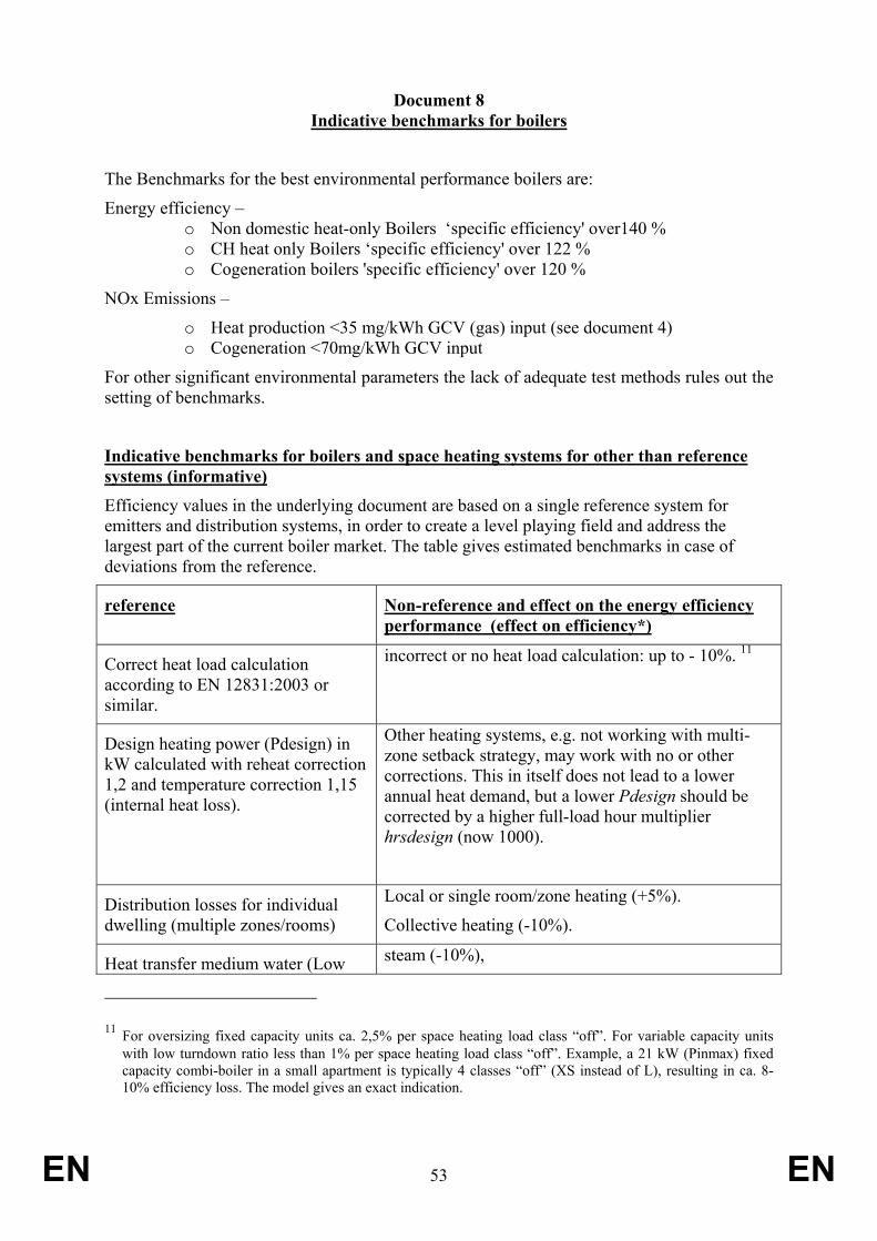
EN 53 EN
Document 8 Indicative benchmarks for boilers
The Benchmarks for the best environmental performance boilers are:
Energy efficiency – o Non domestic heat-only Boilers ‘specific efficiency' over140 % o CH heat only Boilers ‘specific efficiency' over 122 % o Cogeneration boilers 'specific efficiency' over 120 %
NOx Emissions –
o Heat production <35 mg/kWh GCV (gas) input (see document 4) o Cogeneration <70mg/kWh GCV input
For other significant environmental parameters the lack of adequate test methods rules out the setting of benchmarks.
Indicative benchmarks for boilers and space heating systems for other than reference systems (informative) Efficiency values in the underlying document are based on a single reference system for emitters and distribution systems, in order to create a level playing field and address the largest part of the current boiler market. The table gives estimated benchmarks in case of deviations from the reference.
reference Non-reference and effect on the energy efficiency performance (effect on efficiency*)
Correct heat load calculation according to EN 12831:2003 or similar.
incorrect or no heat load calculation: up to - 10%. 11
Design heating power (Pdesign) in kW calculated with reheat correction 1,2 and temperature correction 1,15 (internal heat loss).
Other heating systems, e.g. not working with multi-zone setback strategy, may work with no or other corrections. This in itself does not lead to a lower annual heat demand, but a lower Pdesign should be corrected by a higher full-load hour multiplier hrsdesign (now 1000).
Distribution losses for individual dwelling (multiple zones/rooms)
Local or single room/zone heating (+5%).
Collective heating (-10%).
Heat transfer medium water (Low steam (-10%),
11 For oversizing fixed capacity units ca. 2,5% per space heating load class “off”. For variable capacity units with low turndown ratio less than 1% per space heating load class “off”. Example, a 21 kW (Pinmax) fixed capacity combi-boiler in a small apartment is typically 4 classes “off” (XS instead of L), resulting in ca. 8-10% efficiency loss. The model gives an exact indication.

EN 54 EN
Temperature) air-ducts (-10%), refrigerant (-5%).
LT radiators floor/ wall heating (FOS, FOSB driven) +10% floor/ wall heating (HP driven) +20% HT radiators and/or convectors –10%
Multi-zone setback regime** single-zone setback (-2%)
no setback (-8 %, residential)
no setback (-25%, commercial)
Room temperature control with modulating room-thermostat or weather controlled corrected by room-thermostat.
on-off thermostats or weather controlled without room temperature correction(-2%, equivalent of ‘ext. T-control’ option),
only boiler thermostat (-20%)
Hydraulically balanced (manually) installation
unbalanced installations weather control without central room thermostat (-6%)
unbalanced installations with central room thermostat (-4%).
automatically balanced installation (+4%, equivalent of ‘Multi TV’ control option)
*=note that values are indicative; the effects on the system efficiency depend very much on the local installation.
**=in the model simplified to ‘night-setback’ but values derived from a regime with also day-setback periods for bathroom and bedrooms.