Eclipse Ballooning Project - WordPress · Eclipse Ballooning Project Team: Abigail Sydnes, ......
46
Senior Design II, Slide 1 Eclipse Ballooning Project Team: Abigail Sydnes, Dmitriy Yarmaliuk, Edward MacMurchy & Michael Mazzanti Faculty Advisor: Dr. John J. Helferty The Parliament
Transcript of Eclipse Ballooning Project - WordPress · Eclipse Ballooning Project Team: Abigail Sydnes, ......

Senior Design II, Slide 1
Eclipse Ballooning Project
Team: Abigail Sydnes, Dmitriy Yarmaliuk, Edward
MacMurchy & Michael Mazzanti
Faculty Advisor: Dr. John J. Helferty
The Parliament

Senior Design II, Slide 2
Introduction

Senior Design II, Slide 3
Introduction

Senior Design II, Slide 4
Iridium Modem communicates
with ground laptop via Internet
and satellite communication.
Video payload and ground station
communicate using Ubiquiti
Rocket M5 Modems.
OCCAMS Cut Down payload
receives commands from
Iridium Modem.
Introduction

Senior Design II, Slide 5
Reliable means of video capture
Sensor and Tracking data from full
launch
360° Video Capture Capability
Extensive testing to guarantee
project success
Introduction - Proposed Deliverables
Senior Design II, Slide 6
Problem Statement

Senior Design II, Slide 7
Problem Statement
Launch Date: August 21, 2017
Trigg County High School, Cadiz, Kentucky
Test Launch: April 11, 2017
Roundtop Mountain Resort Lewisberry, PA
Purpose
Stream stable, targeted video of solar eclipse to
the NASA Stream website for entirety of
event
360° Video Camera recording entire flight
Coordinate nationally with other schools to
make recording of historic eclipse
Senior Design II, Slide 8
Design Constraints

Senior Design II, Slide 9
Design Constraints
Maximum weight of HAB (including
2000 gram balloon) of 12lbs.
Environmental temperatures as
low as -55°C.
Robust payload design able to
pass through jetstream
unscathed.
Launch location avoiding any
inclement weather. Additionally,
avoidance of any airports or
similar restricted airspace.
Senior Design II, Slide 10
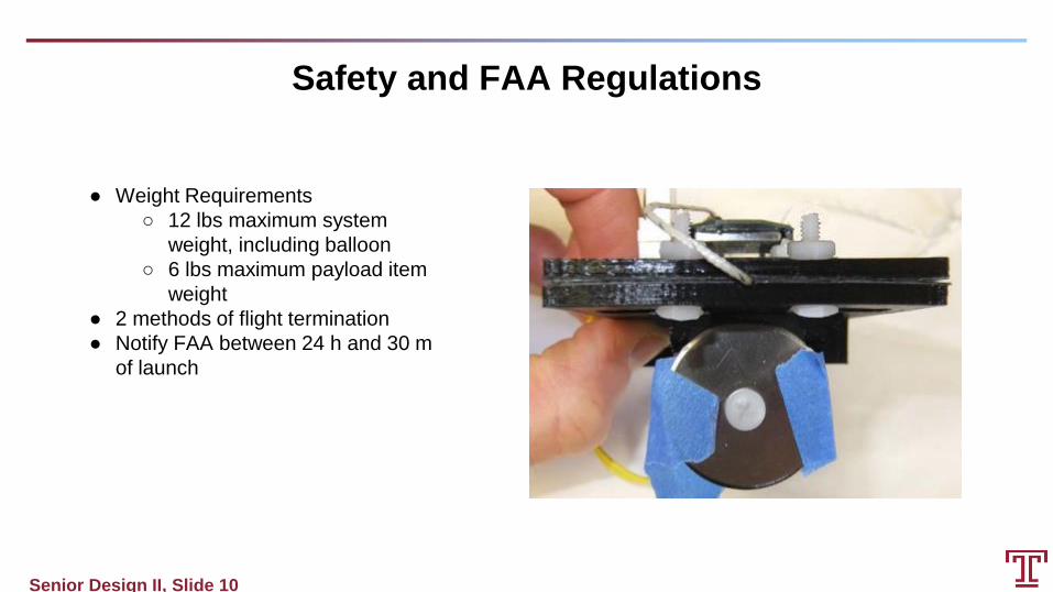
● Weight Requirements
○ 12 lbs maximum system
weight, including balloon
○ 6 lbs maximum payload item
weight
● 2 methods of flight termination
● Notify FAA between 24 h and 30 m
of launch
Safety and FAA Regulations

Senior Design II, Slide 11
Evolution of Design

Senior Design II, Slide 12
Evolution of Design - Montana State University Workshop

Senior Design II, Slide 13
Evolution of Design - Inclusion of 360° Camera
On top of having a streamed
tracking video, a 360°
video would provide a full
environment view upon
recovery of the HAB.
Mounting options and low
weight (7 oz) of 360°
camera allow for easy
inclusion in any payload
design.
In the event of complications
with video payload
streaming or tracking,
eclipse is guaranteed to
be captured.

Senior Design II, Slide 14
Evolution of Design - Removal of Still Image Payload
Weight of payload prevented additional devices from
being added without surpassing 12lbs.
Live video feed along with still images would be
redundant.
Quality of streamed video is slightly lower in
resolution.
Video payload stores camera feed on-board and
uninterrupted video may be obtained after recovery.
360° video camera Nikon KeyMission 360 provides
high quality, full environment view.
KeyMission does not allow for streaming.
Senior Design II, Slide 15
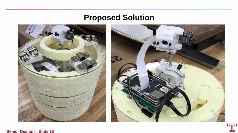
Proposed Solution

Senior Design II, Slide 16
Proposed Solution
Software Design - Autonomous System
Raspberry Pi utilized for image processing
and manual control of camera
positioning.
Pi camera used for the purpose of
capturing video footage.
Made use of the OpenCV library that is
aimed at real-time computer vision.
Allowed for analyzing the captured
video frame by frame.
Made use of the WiringPi Python library.
Utilized to manage and alter the
PWM clock frequency of the
Raspberry Pi.

Senior Design II, Slide 17
Proposed Solution
Software Design - Autonomous System
Each frame is converted to
monochrome and then
blurred.
The magnitudes of the darkest
and brightest pixels within the
frame are identified.
A light intensity value is
determined for each frame
using binary thresholding.
A Python dictionary is used to
store light intensity/brightness
values and their
corresponding positions.

Senior Design II, Slide 18
Proposed Solution
Software Design - Autonomous System
A thresholded image is generated using the
blurred image and the previously outlined
brightest pixel value.
The Canny edge detection algorithm is
applied to the thresholded image.
Light contours identified
Each contour is a NumPy array of (x,y)
coordinates associated with the
boundary points of the object.
Contours sorted based on the radius of
a minimum enclosing circle around
the identified brightest object.
The position of the brightest object is
outlined in terms of pixels.

Senior Design II, Slide 19
Proposed Solution
Software Design - Autonomous System
Each video frame is set up to be 400 by
300 pixels.
Pixel deviation of the brightest object
from the center of the frame in
terms of the x axis is converted to a
degree value.
Horizontal field of view
associated with the
Raspberry Pi camera is
53.5°.
The deviation value in degrees is then
converted to a step count.
Stepper motor makes 513 steps
per revolution.

Senior Design II, Slide 20
Proposed Solution
Software Design - Autonomous System
Pixel deviation of the brightest object
from the center of the frame in
terms of the y axis is converted to
a degree value.
Vertical field of view associated
with the Raspberry Pi
camera is 41.4°.
The deviation value in degrees is
then converted to a PWM signal
required to move the servo motor
to the required position.
Servo motor has 180 degrees
of motion.

Senior Design II, Slide 21
Proposed Solution
Software Design - Manual System (Stepper motor control)
Each stroke of the left or right arrow
key is mapped to 25 steps of the
stepper motor.
Current position of stepper is
updated and stored with
every change in position.
If the next required position of
the motor exceeds 180
degrees the stepper spins
back on itself moving to the
required position from the
opposite side.
Prevents damage of
cables during flight.

Senior Design II, Slide 22
Proposed Solution
Software Design - Manual System (Servo motor control)
Each stroke of the up or down arrow key
is mapped to 10 degrees of
movement for the servo motor.
Current position of servo is
updated and stored with every
change in position.
Subdivided the Raspberry Pi
PWM clock which has a base
frequency of 19.2 MHz.
Provided a stable means of
setting up pulse width
modulation at 50 Hz.

Senior Design II, Slide 23
Coil A1 = Pin 31
Coil A2 = Pin 33
Coil B1 = Pin 35
Coil B2 = Pin 37
Driver board is attached vio GPIO pins
Proposed Solution
Hardware Design

Senior Design II, Slide 24
● Coil activated in series
● 513 steps/rev
● Activation of coils determines the direction
Proposed Solution
Hardware Design
Clockwise Step # Winding A Winding B Winding C Winding D Counter-
Clockwise
1 1 0 0 1
2 1 1 0 0
3 0 1 1 0
4 0 0 1 1

Senior Design II, Slide 25
GPIO pin 18 is used for the purpose of
generating the pulse width modulation
necessary to control the positioning of
the servo motor.
Proposed Solution
Hardware Design

Senior Design II, Slide 26
Proposed Solution
Hardware Design
PWM signals with pulse widths of
0.53 ms and 2.13 ms at a frequency
of 50Hz are used to drive the servo
motor to the extreme left and right
positions respectively.
PWM signal with a pulse width of
1.33 ms at a frequency of 50Hz is
used to drive the servo motor to
the center position.
A 0.0088 ms change in the
pulse width of the PWM signal
corresponds to 1 degree of
servo movement.

Senior Design II, Slide 27
● 2 DOF system to aim camera
● Mitigate and minimize external rotational
forces
○ Cylindrical package design
○ Drag damping moment arms
○ Multiple support lines limit twist
● Decouple video payload from balloon
○ Load-rated ball-bearing swivel
● Eliminate internal rotational effects
○ Eliminate induced torque of main
scanning motor using counterweight
Proposed Solution
Mechanical Targeting and Stabilization System
Senior Design II, Slide 28
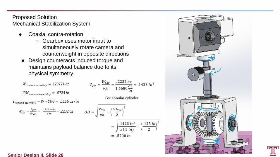
● Coaxial contra-rotation
○ Gearbox uses motor input to
simultaneously rotate camera and
counterweight in opposite directions
● Design counteracts induced torque and
maintains payload balance due to its
physical symmetry.
Proposed Solution
Mechanical Stabilization System

Senior Design II, Slide 29
● Layered Payload
○ .75” polystyrene insulation protects
payload components
○ Acrylic plates provide hardpoints for
component installation and rigging
● Extensive use of nylon hardware keeps
weight low
● Cast acrylic dome allows for clear view of
sky
● Total video payload weight: 5.06 lb
Proposed Solution
Video Payload Design

Senior Design II, Slide 30
● Determine ballast weight required for 5 m/s
ascent rate
● Wpayload + Wballoon = Wnet (14.41 lb)
● Wgross = 1.28 x Wnet (18.44 lb)
● Wneck = Wgross - Wballoon (14.03 lb)
● Wballast = Wgross - Wfill valve = (13.5 lb)
● Set ballast weight using fish scale, then
attach ballast to balloon until the balloon
just lifts the ballast
● Cleared for liftoff!
Balloon Fill Requirements

Senior Design II, Slide 31
● 1500 ft/min maximum allowable descent
rate
● 1.5 NASA safety factor for unmanned
descent
● Drag coefficient is 1.75 for dome-shaped
chute
● At terminal velocity, drag force equals
gravitational force
Parachute Sizing
Senior Design II, Slide 32
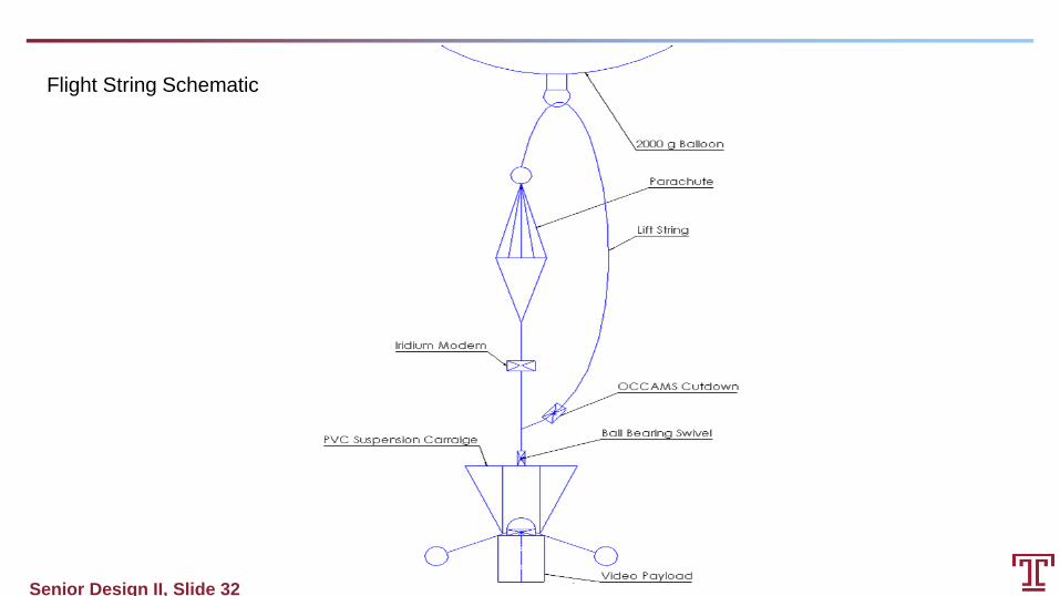
Flight String Schematic

Senior Design II, Slide 33
Testing Methods and Results

Senior Design II, Slide 34
Testing Methods and Results - Autonomous Tracking System

Senior Design II, Slide 35

Senior Design II, Slide 36

Senior Design II, Slide 37
Testing Methods and Results - Test Launch

Senior Design II, Slide 38
Testing Methods and Results - Test Launch Continued
Flight Path Prediction Test Launch Flight Path

Senior Design II, Slide 39
Testing Methods and Results - Test Launch Continued

Senior Design II, Slide 40
Testing Methods and Results - Improvements for the future
● Damage Report
○ Top acrylic plate
○ Three foam rings
○ 3D-printed camera mount
● Assessment
○ All damaged items resulted from
payload recovery. Approximately 15
foot free fall from tree to ground.
● Solution
○ Just have someone catch the thing.

Senior Design II, Slide 41
Testing Methods and Results - Improvements for the future
● Release of objects in flight string can be
done smoother to dampen pendular motion
during ascent.
● Had connection issues with the video
payload.
○ Were able to connect to the payload
from the Ground Station laptop over
SSH once the Ubiquiti modem on the
Ground Station had four bars.
■ Likely due to issues with the
Ground Station using the Iridium
system to automatically point
the dish towards the location of
the balloon.

Senior Design II, Slide 42
Testing Methods and Results - Improvements for the future
● The video of the flight onboard the
Raspberry Pi got interrupted when the
balloon popped.
○ Once the successful test of the
manual control of the Pi camera was
completed the camera was left
pointing up at the balloon.
○ In the video it is possible to see the
balloon expanding.
○ Thus, once the balloon popped it
must of hit the video payload thereby
bringing the video capturing to an
end.

Senior Design II, Slide 43
Testing Methods and Results - Improvements for the future
● Cutdown System failed to trigger cutdown
event with remote email packet.
○ Timer was set and activated when
desired, however the blade became
stuck on the plastic casing due to a
slight offset when the blade was
screwed to the DC motor
● Balloon ascended until burst around 96000 ft

Senior Design II, Slide 44
Future Usage
Eclipse in April 8, 2024
Documentation and implementation for future
Temple ballooning teams
Construction of ground station for senior design
team starting in Fall 2017
Possible addition of higher quality camera
Senior Design II, Slide 45
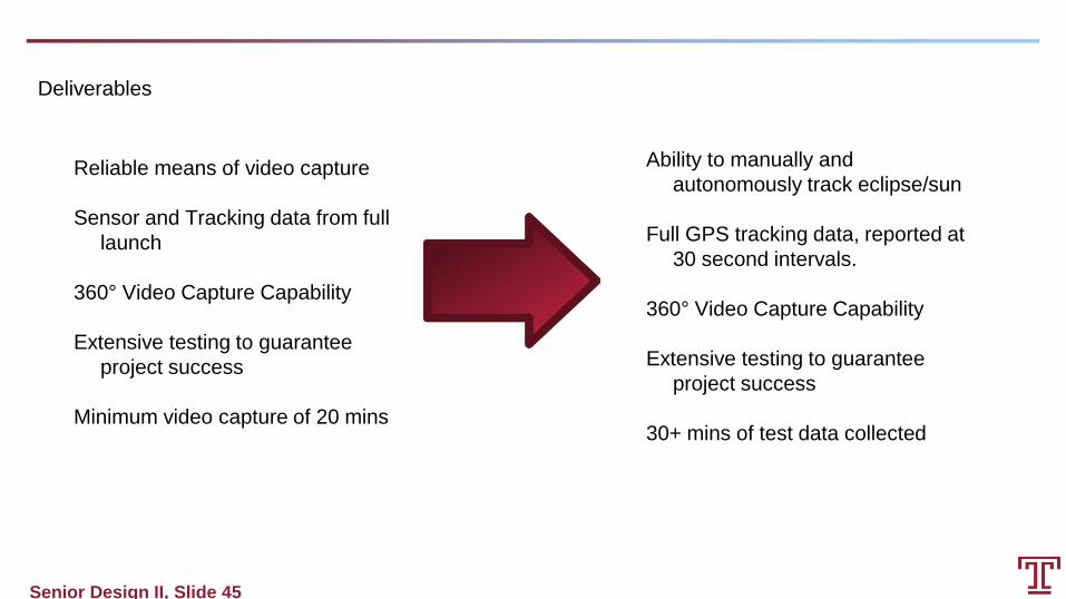
Reliable means of video capture
Sensor and Tracking data from full
launch
360° Video Capture Capability
Extensive testing to guarantee
project success
Minimum video capture of 20 mins
Deliverables
Ability to manually and
autonomously track eclipse/sun
Full GPS tracking data, reported at
30 second intervals.
360° Video Capture Capability
Extensive testing to guarantee
project success
30+ mins of test data collected

Senior Design II, Slide 46
Thanks for Listening!