Echocardiography in the Management of Patients with...
57
ASE GUIDELINES & STANDARDS Echocardiography in the Management of Patients with Left Ventricular Assist Devices: Recommendations from the American Society of Echocardiography Raymond F. Stainback, MD, FASE, Chair, Jerry D. Estep, MD, FASE, Co-Chair, Deborah A. Agler, RCT, RDCS, FASE, Emma J. Birks, MD, PhD, Merri Bremer, RN, RDCS, EdD, FASE, Judy Hung, MD, FASE, James N. Kirkpatrick, MD, FASE, Joseph G. Rogers, MD, and Nishant R. Shah, MD, MSc, Houston, Texas; Cleveland, Ohio; Louisville, Kentucky; Rochester, Minnesota; Boston, Massachusetts; Philadelphia, Pennsylvania; and Durham, North Carolina (J Am Soc Echocardiogr 2015;28:853-909.) Keywords: Echocardiography, mechanical circulatory support, left ventricular assist devices, comprehensive examination TABLE OF CONTENTS Introduction 854 Left Ventricular Assist Devices 855 The Role of Echocardiography in Candidate Selection 856 LV Dysfunction 856 RV Dysfunction 857 Valve Disease 857 Congenital Heart Disease 858 Other High-Risk Findings 859 Perioperative Transesophageal Echocardiography 860 Preimplantation TEE 860 PerioperativeTEE During LVAD Implantation 860 Perioperative TEE During Initial LVADActivation and Speed Optimization 860 Role of Echocardiography (TTE or TEE) After LVAD Implantation 865 LVAD Surveillance Echocardiography 865 Echocardiography with Speed Changes and Safety Concerns 874 LVAD Optimization Echocardiography 876 LVAD Problem-Focused Echocardiography 878 Echocardiographic Assessment of Abnormal LVADAlarms 882 LVAD Recovery Echo Exam 888 LVADs for Pediatric and Adolescent Patients 888 Other Areas of Research 890 Indications for Other Imaging Methods After LVAD Implantation 890 Summary/Discussion 890 Patient Populations 891 Frequency and Extent of Echocardiography 891 Laboratory Resources and Extent of Examination 891 Referring/Community Hospitals 891 Other Devices 892 The Right Ventricle and Biventricular/RVAD Support 892 Notice and Disclaimer 892 Acknowledgments 892 References 892 Appendix A: Other FDA-Approved Pumps that may be Encountered 896 Percutaneous LVADs for Temporary Support 896 Surgically Implanted Extracorporeal Ventricular Assist Devices for Temporary Support 896 Right Ventricular Assist Devices 898 Appendix B: Recommended Pre-LVAD-implantation TTE Protocol 901 Appendix C: Perioperative TEE Protocol/Checklist 903 Appendix D: Magnitude and Time Course of Echo LV Parameter Changes Induced by CF-LVAD Unloading 904 Appendix E: LVAD Surveillance Echo Protocol 906 Appendix F: LVAD Optimization/Ramp Echo Protocol 907 Appendix G: Speed Changes: LVAD Optimization or Problem-Focused (Ramp) Protocol Worksheet 908 Appendix H: LVAD Recovery Protocol Worksheet 909 From the Texas Heart Institute, Houston, Texas (R.F.S.); Houston Methodist, Houston, Texas (J.D.E.); Cleveland Clinic, Cleveland, Ohio (D.A.A.); University of Louisville School of Medicine, Louisville, Kentucky (E.J.B.); Mayo Clinic, Rochester, Minnesota (M.B.); Massachusetts General Hospital, Boston, Massachusetts (J.H.); Hospital of the University of Pennsylvania, Philadelphia, Pennsylvania (J.N.K.); Duke University Hospital, Durham, North Carolina (J.G.R.); and Brigham and Women’s Hospital, Boston, Massachusetts (N.R.S.). Special contributions by Madhav Swaminathan, MD, FASE (ASE Council on Peri- operative Echocardiography) and Theresa A. Tacy, MD (ASE Council on Pediatric and Congenital Heart Disease). Authors are listed alphabetically. The following authors reported no actual or potential conflicts of interest rela- tive to this document: Raymond F. Stainback, MD, FASE; Deborah A. Agler, RCT, RDCS, FASE; Emma J. Birks, MD, PhD; Merri Bremer, RN, RDCS, EdD, FASE; Judy Hung, MD, FASE; James N. Kirkpatrick, MD, FASE; Joseph G. Rogers, MD. The following author reported relationships with one or more commercial interests: Nishant R. Shah, MD, MSc, holds stock in GE. Jerry D. Estep, MD, FASE, serves as a consultant for Thoratec, Inc. and Maquet, Inc. Attention ASE Members: The ASE has gone green! Visit www.aseuniversity.org to earn free continuing medical education credit through an online activity related to this article. Certificates are available for immediate access upon successful completion of the activity. Nonmembers will need to join the ASE to access this great member benefit! Reprint requests: American Society of Echocardiography, 2100 Gateway Centre Boulevard, Suite 310, Morrisville, NC 27560 (E-mail: [email protected]). 0894-7317/$36.00 Copyright 2015 by the American Society of Echocardiography. http://dx.doi.org/10.1016/j.echo.2015.05.008 853
-
Upload
nguyenxuyen -
Category
Documents
-
view
230 -
download
4
Transcript of Echocardiography in the Management of Patients with...

ASE GUIDELINES & STANDARDS
From the Tex
Houston, Tex
Louisville Sc
Rochester, M
Massachuset
Pennsylvania
(J.G.R.); and B
Special contr
operative Ech
and Congenit
Authors are lis
The following
tive to this d
RCT, RDCS,
EdD, FASE; J
G. Rogers, M
Echocardiography in the Management of Patients withLeft Ventricular Assist Devices: Recommendationsfrom the American Society of Echocardiography
Raymond F. Stainback, MD, FASE, Chair, Jerry D. Estep, MD, FASE, Co-Chair, Deborah A. Agler, RCT, RDCS,FASE, Emma J. Birks, MD, PhD, Merri Bremer, RN, RDCS, EdD, FASE, Judy Hung, MD, FASE,
James N. Kirkpatrick, MD, FASE, Joseph G. Rogers, MD, and Nishant R. Shah, MD, MSc, Houston, Texas;Cleveland, Ohio; Louisville, Kentucky; Rochester, Minnesota; Boston, Massachusetts; Philadelphia, Pennsylvania;
and Durham, North Carolina
(J Am Soc Echocardiogr 2015;28:853-909.)
Keywords: Echocardiography, mechanical circulatory support, left ventricular assist devices, comprehensiveexamination
TABLE OF CONTENTS
Introduction 854Left Ventricular Assist Devices 855The Role of Echocardiography in Candidate Selection 856LV Dysfunction 856RV Dysfunction 857Valve Disease 857Congenital Heart Disease 858Other High-Risk Findings 859Perioperative Transesophageal Echocardiography 860Preimplantation TEE 860Perioperative TEE During LVAD Implantation 860Perioperative TEE During Initial LVAD Activation and SpeedOptimization 860
Role of Echocardiography (TTE or TEE) After LVAD Implantation 865LVAD Surveillance Echocardiography 865Echocardiography with Speed Changes and Safety Concerns 874LVAD Optimization Echocardiography 876LVAD Problem-Focused Echocardiography 878Echocardiographic Assessment of Abnormal LVAD Alarms 882LVAD Recovery Echo Exam 888LVADs for Pediatric and Adolescent Patients 888Other Areas of Research 890Indications for Other Imaging Methods After LVAD Implantation 890Summary/Discussion 890
as Heart Institute, Houston, Texas (R.F.S.); Houston Methodist,
as (J.D.E.); Cleveland Clinic, Cleveland, Ohio (D.A.A.); University of
hool of Medicine, Louisville, Kentucky (E.J.B.); Mayo Clinic,
innesota (M.B.); Massachusetts General Hospital, Boston,
ts (J.H.); Hospital of the University of Pennsylvania, Philadelphia,
(J.N.K.); Duke University Hospital, Durham, North Carolina
righam and Women’s Hospital, Boston, Massachusetts (N.R.S.).
ibutions byMadhav Swaminathan,MD, FASE (ASECouncil on Peri-
ocardiography) and Theresa A. Tacy, MD (ASE Council on Pediatric
al Heart Disease).
ted alphabetically.
authors reported no actual or potential conflicts of interest rela-
ocument: Raymond F. Stainback, MD, FASE; Deborah A. Agler,
FASE; Emma J. Birks, MD, PhD; Merri Bremer, RN, RDCS,
udy Hung, MD, FASE; James N. Kirkpatrick, MD, FASE; Joseph
D. The following author reported relationships with one or more
Patient Populations 891Frequency and Extent of Echocardiography 891Laboratory Resources and Extent of Examination 891Referring/Community Hospitals 891Other Devices 892The Right Ventricle and Biventricular/RVAD Support 892Notice and Disclaimer 892Acknowledgments 892References 892Appendix A: Other FDA-Approved Pumps that may beEncountered 896
Percutaneous LVADs for Temporary Support 896Surgically Implanted Extracorporeal Ventricular Assist Devices forTemporary Support 896
Right Ventricular Assist Devices 898Appendix B: Recommended Pre-LVAD-implantation TTE Protocol 901Appendix C: Perioperative TEE Protocol/Checklist 903Appendix D: Magnitude and Time Course of Echo LV Parameter ChangesInduced by CF-LVAD Unloading 904
Appendix E: LVAD Surveillance Echo Protocol 906Appendix F: LVAD Optimization/Ramp Echo Protocol 907Appendix G: Speed Changes: LVAD Optimization or Problem-Focused(Ramp) Protocol Worksheet 908
Appendix H: LVAD Recovery Protocol Worksheet 909
commercial interests: Nishant R. Shah, MD, MSc, holds stock in GE. Jerry D.
Estep, MD, FASE, serves as a consultant for Thoratec, Inc. and Maquet, Inc.
Attention ASE Members:
The ASE has gone green! Visit www.aseuniversity.org to earn free continuing
medical education credit through an online activity related to this article.
Certificates are available for immediate access upon successful completion
of the activity. Nonmembers will need to join the ASE to access this great
member benefit!
Reprint requests: American Society of Echocardiography, 2100 Gateway Centre
Boulevard, Suite 310, Morrisville, NC 27560 (E-mail: [email protected]).
0894-7317/$36.00
Copyright 2015 by the American Society of Echocardiography.
http://dx.doi.org/10.1016/j.echo.2015.05.008
853
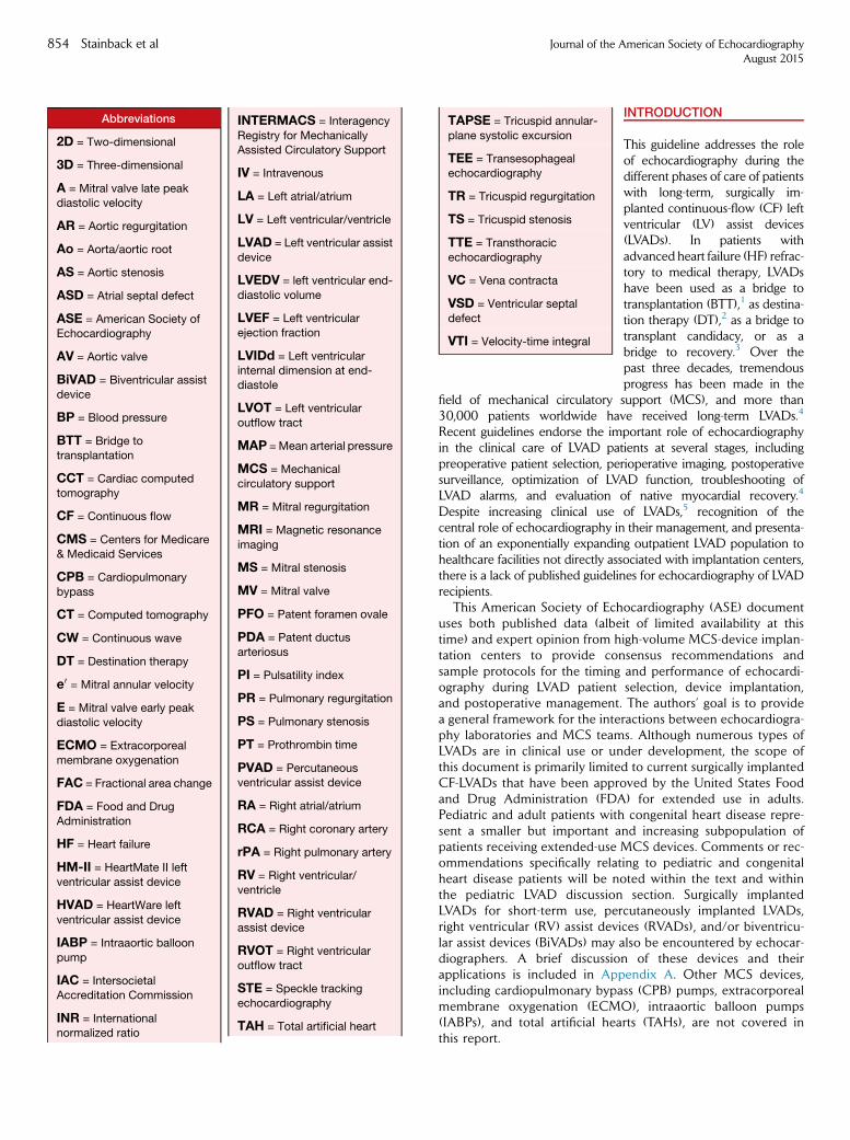
Abbreviations
2D = Two-dimensional
3D = Three-dimensional
A = Mitral valve late peak
diastolic velocity
AR = Aortic regurgitation
Ao = Aorta/aortic root
AS = Aortic stenosis
ASD = Atrial septal defect
ASE = American Society ofEchocardiography
AV = Aortic valve
BiVAD = Biventricular assistdevice
BP = Blood pressure
BTT = Bridge totransplantation
CCT = Cardiac computedtomography
CF = Continuous flow
CMS = Centers for Medicare& Medicaid Services
CPB = Cardiopulmonarybypass
CT = Computed tomography
CW = Continuous wave
DT = Destination therapy
e0 = Mitral annular velocity
E = Mitral valve early peak
diastolic velocity
ECMO = Extracorporeal
membrane oxygenation
FAC = Fractional area change
FDA = Food and Drug
Administration
HF = Heart failure
HM-II = HeartMate II left
ventricular assist device
HVAD = HeartWare left
ventricular assist device
IABP = Intraaortic balloon
pump
IAC = IntersocietalAccreditation Commission
INR = Internationalnormalized ratio
INTERMACS = Interagency TAPSE = Tricuspid annular-
854 Stainback et al Journal of the American Society of EchocardiographyAugust 2015
Registry for MechanicallyAssisted Circulatory Support
IV = Intravenous
LA = Left atrial/atrium
LV = Left ventricular/ventricle
LVAD = Left ventricular assist
device
LVEDV = left ventricular end-
diastolic volume
LVEF = Left ventricularejection fraction
LVIDd = Left ventricularinternal dimension at end-
diastole
LVOT = Left ventricular
outflow tract
MAP =Mean arterial pressure
MCS = Mechanical
circulatory support
MR = Mitral regurgitation
MRI = Magnetic resonance
imaging
MS = Mitral stenosis
MV = Mitral valve
PFO = Patent foramen ovale
PDA = Patent ductus
arteriosus
PI = Pulsatility index
PR = Pulmonary regurgitation
PS = Pulmonary stenosis
PT = Prothrombin time
PVAD = Percutaneous
ventricular assist device
RA = Right atrial/atrium
RCA = Right coronary artery
rPA = Right pulmonary artery
RV = Right ventricular/ventricle
RVAD = Right ventricularassist device
RVOT = Right ventricularoutflow tract
STE = Speckle tracking
echocardiography
TAH = Total artificial heart
plane systolic excursion
TEE = Transesophagealechocardiography
TR = Tricuspid regurgitation
TS = Tricuspid stenosis
TTE = Transthoracic
echocardiography
VC = Vena contracta
VSD = Ventricular septal
defect
VTI = Velocity-time integral
INTRODUCTION
This guideline addresses the roleof echocardiography during thedifferent phases of care of patientswith long-term, surgically im-planted continuous-flow (CF) leftventricular (LV) assist devices(LVADs). In patients withadvanced heart failure (HF) refrac-tory to medical therapy, LVADshave been used as a bridge totransplantation (BTT),1 as destina-tion therapy (DT),2 as a bridge totransplant candidacy, or as abridge to recovery.3 Over thepast three decades, tremendousprogress has been made in the
field of mechanical circulatory support (MCS), and more than30,000 patients worldwide have received long-term LVADs.4
Recent guidelines endorse the important role of echocardiographyin the clinical care of LVAD patients at several stages, includingpreoperative patient selection, perioperative imaging, postoperativesurveillance, optimization of LVAD function, troubleshooting ofLVAD alarms, and evaluation of native myocardial recovery.4
Despite increasing clinical use of LVADs,5 recognition of thecentral role of echocardiography in their management, and presenta-tion of an exponentially expanding outpatient LVAD population tohealthcare facilities not directly associated with implantation centers,there is a lack of published guidelines for echocardiography of LVADrecipients.
This American Society of Echocardiography (ASE) documentuses both published data (albeit of limited availability at thistime) and expert opinion from high-volume MCS-device implan-tation centers to provide consensus recommendations andsample protocols for the timing and performance of echocardi-ography during LVAD patient selection, device implantation,and postoperative management. The authors’ goal is to providea general framework for the interactions between echocardiogra-phy laboratories and MCS teams. Although numerous types ofLVADs are in clinical use or under development, the scope ofthis document is primarily limited to current surgically implantedCF-LVADs that have been approved by the United States Foodand Drug Administration (FDA) for extended use in adults.Pediatric and adult patients with congenital heart disease repre-sent a smaller but important and increasing subpopulation ofpatients receiving extended-use MCS devices. Comments or rec-ommendations specifically relating to pediatric and congenitalheart disease patients will be noted within the text and withinthe pediatric LVAD discussion section. Surgically implantedLVADs for short-term use, percutaneously implanted LVADs,right ventricular (RV) assist devices (RVADs), and/or biventricu-lar assist devices (BiVADs) may also be encountered by echocar-diographers. A brief discussion of these devices and theirapplications is included in Appendix A. Other MCS devices,including cardiopulmonary bypass (CPB) pumps, extracorporealmembrane oxygenation (ECMO), intraaortic balloon pumps(IABPs), and total artificial hearts (TAHs), are not covered inthis report.
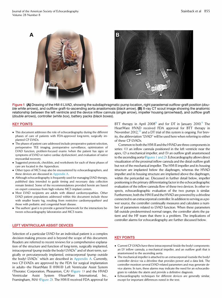
Figure 1 (A)Drawing of the HM-II LVAD, showing the subdiaphragmatic pump location, right parasternal outflow-graft position (dou-ble white arrows), and outflow graft-to-ascending aorta anastomosis (black arrow). (B) X-ray CT scout image showing the anatomicrelationship between the left ventricle and the device inflow cannula (single arrow), impeller housing (arrowhead), and outflow graft(double arrows), controller (white box), battery packs (black boxes).
Journal of the American Society of EchocardiographyVolume 28 Number 8
Stainback et al 855
KEY POINTS
� This document addresses the role of echocardiography during the differentphases of care of patients with FDA-approved long-term, surgically im-planted CF-LVADs.
� The phases of patient care addressed include preoperative patient selection,perioperative TEE imaging, postoperative surveillance, optimization ofLVAD function, problem-focused exams (when the patient has signs orsymptoms of LVAD or native cardiac dysfunction), and evaluation of nativemyocardial recovery.
� Suggested protocols, checklists, and worksheets for each of these phases ofcare are located in the Appendices.
� Other types of MCS may also be encountered by echocardiographers, andthese devices are discussed in Appendix A.
� Although echocardiography is frequently used for managing LVAD therapy,published data intended to guide timing and necessary data collectionremain limited. Some of the recommendations provided herein are basedon expert consensus from high-volume MCS implant centers.
� Most LVAD recipients are adults with dilated cardiomyopathies. OtherLVAD patient populations addressed within this document include thosewith smaller hearts (eg, resulting from restrictive cardiomyopathies) andthose with pediatric and congenital heart disease.
� The authors’ goal is to provide a general framework for the interactions be-tween echocardiography laboratories and MCS teams.
LEFT VENTRICULAR ASSIST DEVICES
Selection of a particular LVAD for an individual patient is a complexdecision-making process and is beyond the scope of this document.Readers are referred to recent reviews for a comprehensive explana-tion of the structure and function of long-term, surgically implanted,intracorporeal (pump inside the body) LVADs6 and of short-term, sur-gically or percutaneously implanted, extracorporeal (pump outsidethe body) LVADs7 which are described in Appendix A. Currently,two CF-LVADs are approved by the FDA for surgical implantationin adults—the HeartMate II (HM-II) Left Ventricular Assist System(Thoratec Corporation, Pleasanton, CA) (Figure 1) and the HVADVentricular Assist System (HeartWare International, Inc.,Framingham, MA) (Figure 2). The HM-II received FDA approval for
BTT therapy in April 20088 and for DT in January 2010.9 TheHeartWare HVAD received FDA approval for BTT therapy inNovember 2012,10 and a DT trial of this system is ongoing. For brev-ity, the abbreviation ‘‘LVAD’’ will be used here when referring to eitherof these CF-LVADs.
Common to both theHM-II and theHVADare three components inseries: (1) an inflow cannula positioned in the left ventricle near theapex, (2) a mechanical impeller, and (3) an outflow graft anastomosedto the ascending aorta (Figures 1 and2). Echocardiography allowsdirectvisualization of the proximal inflow cannula and the distal outflow graftbut not of the mechanical impeller. The HM-II impeller and its housingstructure are implanted below the diaphragm, whereas the HVADimpeller and its housing structure are implanted above the diaphragm,within the pericardial sac. Discussed in further detail below, impellerpositioning is the primary differentiating factor in the echocardiographicevaluation of the inflow-cannula flow of these two devices. In other re-spects, echocardiographic evaluation of the two pumps is similar.Furthermore, both theHM-II and theHVADare poweredby a drivelineconnected to an extracorporeal controller. In addition to serving as a po-wer source, the controller continually measures and calculates a num-ber of parameters related to LVAD function. When these parametersfall outside predetermined normal ranges, the controller alerts the pa-tient and the HF team that there is a problem. The implications ofcontroller alarms for echocardiography are further discussed below.
KEY POINTS
� Current CF-LVADs have three intracorporeal (inside the body) components:an LV inflow cannula, a mechanical impeller, and an outflow graft that isanastomosed to the ascending aorta.
� The mechanical impeller is attached to an extracorporeal (outside the body)controller device via a driveline that provides power and a data link. Thecontroller monitors several LVAD-related parameters and may generate de-vice alarms. In turn, these alarms may indicate the need for an echocardio-gram to validate the alarm and provide a definitive diagnosis.
� Echocardiography techniques for different devices are generally similar,except for important differences noted in the text.

Figure 2 (A) Drawing of the HVAD, showing the intrapericardial pump location, right parasternal outflow graft position (double whitearrows), and outflow graft-to-ascending aorta anastomosis (black arrow). (Courtesy of Heartware, Inc.). (B) X-ray CT scout imageshowing the anatomic relationship between the left ventricle and the device inlet cannula with its attached intrapericardial pump(single arrow). Although not visible here, the outflow graft would typically be imaged in the right parasternal area (double arrows).The asterisk denotes a cardiac implantable electronic device.
856 Stainback et al Journal of the American Society of EchocardiographyAugust 2015
THE ROLE OF ECHOCARDIOGRAPHY IN CANDIDATE
SELECTION
Optimal candidate selection is one of the most important determi-nants of a successful operative and long-term outcome for LVADrecipients.4 Transthoracic echocardiography (TTE) is generally thefirst-line imaging modality used to screen LVAD candidates for struc-tural and/or functional abnormalities that represent absolute or rela-tive contraindications to device implantation. In some cases, patientsrequire urgent or emergent surgical LVAD placement. In these acutesituations, adequate TTE information may be technically limited orunavailable. Therefore, transesophageal echocardiography (TEE) per-formed in the acute setting (catheterization laboratory, emergencydepartment, intensive care unit, or operating room) should addressall of the factors mentioned below with regard to TTE. Given its cen-tral role in LVAD candidate selection, preimplantation TTE or TEE(when necessary) should be performed in a laboratory that hasbeen accredited by the Intersocietal Accreditation Commission(IAC)11 and should be supervised and interpreted by a skilled echocar-diographer12 who is experienced in advanced HF evaluation and thehemodynamic assessment of MCS devices. Preimplantation TTE inLVAD candidates should include all the elements of a comprehensiveexamination as recommended by the ASE,13 with a particular focuson the high-risk or ‘‘red-flag’’ findings detailed below and summarizedin Table 1. A comprehensive, checklist-based preimplantation TTEprotocol with the notation of red-flag findings is available inAppendix B. If preimplantation TTE yields inconclusive findings,TEE may be performed, as described below. If a recently performedhigh-quality TTE exam includes most but not all of the required pre-implantation exam elements and there has been no interval changein the patient’s clinical status, a limited, focused follow-up exam toobtain the additional necessary information may be acceptable.
LV Dysfunction
Severe LV systolic dysfunction resulting from a dilated cardiomyopa-thy characterizes the majority of LVAD recipients. Accordingly, echo-cardiography laboratories must be proficient in techniques formeasuring LV size, ejection fraction (LVEF), and cardiac output.
LV Ejection Fraction. Demonstration of an LVEF of <25% is aCenters for Medicare & Medicaid (CMS)-qualifying condition forLVAD implantation as DT.14 Additionally, the LVEF is a componentof both the Seattle Heart Failure Model15 and the Heart FailureSurvival Score,16 two clinical-risk scoring tools that are widely usedby HF specialists to calculate patients’ expected survival times and,by extension, their suitability for an LVAD. A severely decreasedLVEF is by no means the only clinical parameter used for determiningwhether or not a patient is referred for MCS. However, its accuratemeasurement by echocardiography is of paramount importance.Previous ASE guidelines describe the recommended methods forechocardiographic LV chamber quantification.17-19 On the basis ofthose guidelines, laboratories with the ability and expertise toperform three-dimensional (3D) assessment for determining LV vol-umes and the LVEF should routinely do so when imaging conditionspermit; otherwise, they should use the biplanemethod of disks (modi-fied Simpson’s rule) from two-dimensional (2D) images. Strongconsideration should be given to the use of a microbubble contrastagent when indicated to enhance endocardial definition and improvethe precision of LVEF measurement.20
LV Internal Dimension at End-Diastole. In addition to theLVEF, the LV internal dimension at end-diastole (LVIDd) from 2D par-asternal long-axis images is a critical measurement in LVAD candi-dates. For patients who eventually undergo LVAD implantation,comparison of the preoperative LVIDd to the postoperative LVIDdis the primary clinical measure of the degree of LVAD-mediated LVunloading. Whereas a comparison of pre- and postoperative LVend-diastolic volumes (LVEDVs) would better quantify LV unloading,thesemeasurements can be extremely challenging to obtain in the im-mediate postoperative period, when standard echocardiographicwindows are limited by supine positioning, mechanical ventilation,a recent sternotomy, bandages, and other physical barriers. Whilethe LVIDd and LVEDV are moderately to severely increased inmost patients considered for an LVAD, limited data suggest that asmaller LV cavity, defined by an LVIDd of <63 mm, is associatedwith increased 30-day morbidity and mortality rates after LVAD im-plantation.21 Patients who tend to have smaller LV cavities includeelderly women with a smaller body habitus and persons with

Table 1 Preimplantation TTE/TEE ‘‘red-flag’’ findings
Left Ventricle and Interventricular Septum
Small LV size, particularly with increased LV trabeculation
LV thrombusLV apical aneurysm
Ventricular septal defect
Right Ventricle
RV dilatation
RV systolic dysfunction
Atria, Interatrial Septum, and Inferior Vena Cava
Left atrial appendage thrombus
PFO or atrial septal defect
Valvular Abnormalities
Any prosthetic valve (especially mechanical AV or MV)> mild AR
$ moderate MS
$ moderate TR or > mild TS> mild PS; $ moderate PR
Other
Any congenital heart diseaseAortic pathology: aneurysm, dissection, atheroma, coarctation
Mobile mass lesion
Other shunts: patent ductus arteriosus, intrapulmonary
AR, Aortic regurgitation; AV, aortic valve; LV, left ventricular; MS,
mitral stenosis;MV,mitral valve;PFO, patent foramen ovale;PR, pul-
monary regurgitation; PS, pulmonary stenosis; RV, right ventricle;
TR, tricuspid regurgitation; TS, tricuspid regurgitation.Note: These red-flag findings are found within the Recommended
Pre–LVAD-Implantation TTE Protocol (Appendix B). They are also
found within the Perioperative TEE Protocol/Checklist (AppendixC), which contains additional immediate post-LVAD-implantation
perioperative TEE red-flag findings.
Journal of the American Society of EchocardiographyVolume 28 Number 8
Stainback et al 857
infiltrative cardiomyopathies (eg, amyloidosis). The latter group mayalso have concomitant right-sided HF, another preoperative high-risk finding that is discussed below. Whereas a small LV cavity is notan absolute contraindication to LVAD implantation, the presence ofthis finding should be communicated to the HF team.
Intracardiac Thrombi. An intracardiac thrombus is not an abso-lute contraindication for LVAD implantation but may increase therisk of stroke during the LV cannulation portion of the procedure.At particularly increased risk for LV thrombus are patients with aseverely decreased LVEF and/or an LV aneurysm. In these patients,strong consideration should be given to the use of a microbubblecontrast agent during assessment for LV thrombus. If such a thrombusis identified, the implanting surgeon should be made aware of its sizeand location so that the thrombus can be carefully removed duringdevice implantation. In borderline cases, cardiac computed tomogra-phy (CCT) may be adjunctively used to rule out an LV thrombus.4 Inpatients with atrial fibrillation, who are at increased risk for thrombusin the left atrial appendage, adjunctive TEE may be required for com-plete intracardiac thrombus assessment.
RV Dysfunction
Echocardiographic signs of RV dysfunction include impaired RV sys-tolic function and/or RV dilatation, increased RA pressure (ascer-tained by inferior vena cava size and collapsibility), and moderate orgreater tricuspid regurgitation (TR). Previous ASE guidelines describe
the recommended methods for echocardiographic evaluation of RVfunction and chamber quantification.17,18,22 On the basis of thoseguidelines, 3D echocardiographic assessment of RV volumes tocalculate the RV ejection fraction would be ideal, but the authorsrealize that this approach is technically challenging and not widelyavailable. Measurement of other secondary echocardiographicsurrogates of RV systolic function, including RV fractional areachange (FAC), tricuspid annular-plane systolic excursion (TAPSE),and RV free-wall peak longitudinal strain, can be difficult in patientswith advancedHF.Nonetheless, quantitativemeasures of RV functionare recommended for use whenever possible, but only when able tobe properly measured in a given patient. At a minimum, a qualitativeassessment of RV size and systolic function and of TR severity shouldbe performed and communicated in the interpretation.
Echocardiographic signs of RV dysfunction should not be consideredin isolation. They should be integrated with a patient’s clinical signs andsymptoms of possible right-sided heart failure syndrome. Clinically se-vere preoperativeRVdysfunctionmay prompt theHF team to considerplanned biventricular MCS, as this may lead to better outcomes thandelayed conversion of an LVAD to biventricular MCS.23 Some patientswith less than severe RV dysfunction at preoperative assessment willdevelop severe RV dysfunction after LVAD implantation. This compli-cation, defined by the Interagency Registry for Mechanically AssistedCirculatory Support (INTERMACS)24 as the requirement of an RVassist device (RVAD) or >14 consecutive days of intravenous (IV)inotropic support, has an estimated prevalence of 13% to 44% and isassociated with significant morbidity and mortality.25,26 Preliminarydata suggest that there may be preoperative echocardiographicparameters predictive of severe postoperative RV dysfunction. Instudies that included clinical parameters in their multivariable models,an RV absolute peak longitudinal strain of <9.6%27 and an RV: LVend-diastolic diameter ratio of >0.7528 were identified as potentialindependently predictive echocardiographic parameters. More recentdata by Kato and colleagues29 suggests that the accuracy for predictingpost LVADRV failuremay be improvedwhenmore than one RVecho-cardiographic parameter (in this case RV tissue Doppler imaging andRV speckle tracking imaging [RV longitudinal strain]) are used in aggre-gate. Given the lack of consensus thus far regarding the predictive valueof any single echocardiographic parameter, an aggregate assessment uti-lizing relevant left-sided parameters (eg, indexed left atrial volume, in-dexed LV size) and right-sided parameters (eg, RV parametersdescribed above, TR severity,30 and right atrial [RA] pressure estima-tion) is likely the optimal approach for now.4,31
KEY POINTS
� Nearly all LVAD candidates undergo echocardiography to screen for struc-tural and/or functional abnormalities that preclude LVAD implantation orthat may alter surgical planning.
� At this time, the literature does not support the use of any single echocardio-graphic RV parameter for predicting the post-LVAD prognosis or the needfor biventricular support (RVAD use).
� Quantitative echocardiographic parameters of RV function (whichmay varyamong patients, depending upon imaging conditions), should be integratedwith clinical signs and symptoms to determine the degree of preoperativeRV dysfunction, which may impact the operative plan and/or postoperativeprognosis.
Valve Disease
Previous ASE guidelines address detection and quantitation of valvularregurgitation,32 valvular stenosis,33 and prosthetic valve dysfunction.34

858 Stainback et al Journal of the American Society of EchocardiographyAugust 2015
Valve Stenosis. In patients with advanced HF and a severelyreduced stroke volume, spectral Doppler-derived valve gradients inisolation may not accurately reflect the degree of valvular stenosis. Inthese patients, calculation of the valvular orifice area may be more ac-curate. Moderate or severe mitral valve (MV) stenosis can preventadequate LVAD cannula inflow. Accordingly, significant mitral stenosis(MS) must be corrected before LVAD implantation. In contrast, aorticstenosis (AS) of any severity may be present without affecting LVADfunction, because LVADs completely bypass the native LVoutflow tract(LVOT). It is important to note, however, that patients who have criticalAS or who undergo surgical aortic valve (AV) complete closure to cor-rect aortic regurgitation (AR) will have no forward flow in the event ofobstructive LVAD failure, even if residual LV function is present.
Valve Regurgitation. Exclusion of significant AR before LVAD im-plantation is critical and sometimes challenging. When present atLVAD implantation, significant AR enables a ‘‘blind’’ loop of flow inwhich blood enters the LVAD from the left ventricle, is pumped intothe ascending aorta, but then flows back into the left ventricle throughthe regurgitant aortic valve. Itmay be difficult for echocardiographers todetermine the degree ofARpresent in patientswith advancedHF and aseverely reduced LV stroke volume. Heart failure patients with moder-ate or severe AR may have unimpressive color-flow Doppler imagesand low AR velocities due to low systemic pressures and high LVdiastolic pressures. Additionally, the aortic regurgitant volume may berelatively low, despite a high regurgitant fraction. Accordingly, theDoppler-derived LVOT stroke volume and regurgitant fraction shouldbe calculated routinely when possible.32 Furthermore, there shouldbe a high level of suspicion for significant AR in the presence of aorticroot dilatation, eccentric AR (particularly if associated with a bicommis-sural AV), rheumatic or calcific AV degeneration, or an aortic prosthesis.TEE should be strongly considered when there is any degree of sus-pected abnormal prosthetic valve regurgitation. The presence ofmore than mild AR should be communicated to the implanting sur-geon, because recent guidelines advise confirmation by perioperativeTEE and surgical correction of AR before LVAD implantation.4
Surgical treatment options for significant native valve AR includereplacement with a bioprosthesis, completely oversewing the valve(by suturing along all coaptation zones) or by performing a central coap-tation (Park) stitch.35 Completely over sewing the AV cusps effectivelyeliminates AR, but (asmentioned above) leaves the patient with no fail-safe means of LVejection in the event of LVAD failure. When the aorticcusp integrity is good, a central coaptation (Park) stitch technique cantreat central ARwhile allowing aortic forward flow through the residualcommissural zones to occur during reduced LVADsupport (Figure 3) orin the event of LVAD pump failure.
Mitral regurgitation (MR) that is significant preoperatively is oftenmarkedly improved after initiation of LVAD support, because ofreduced LV size, reduced filling pressures, and improved coaptationof the MV leaflets. For this reason, any degree of MR is acceptablein LVAD candidates. In contrast, moderate or greater TR is a poten-tially ominous finding, which may indicate RV dysfunction asmentioned above. It is important to communicate the presence of sig-nificant TR to the implanting surgeon; recent guidelines recommendthat surgical tricuspid valve repair be considered at the time of LVADimplantation.4 Pulmonary regurgitation (PR)may bemore commonlyencountered in patients with congenital heart disease. In any patient,moderate or greater PR could contribute to preoperative RV dysfunc-tion and would require repair in the event of RVAD implantation.However, PR may be well tolerated in the setting of successfulLVAD implantation with adequate RV function and successful LV un-
loading. However, significant PR could potentially contribute to RVdysfunction after LVAD implantation if pulmonary vascular resistancewere increased for any reason, including acquired pulmonary diseaseor an inability to adequately unload the left ventricle.
Prosthetic Valves. When indicated, prosthetic valve assessment byTTE and TEE is critical for surgical decision-making. LVAD-supportedpatients must receive systemic anticoagulation, regardless of the pres-ence of mechanical prosthetic valves. However, a higher target pro-thrombin time international normalized ratio (PT INR) may benecessary if a mechanical valve is present. After initiation of LVAD sup-port, the inherent reduced flow through a mechanical AV prosthesisfurther increases the risk of postoperative valvular or aortic root throm-bosis and subsequent thromboembolic events. For this reason, replace-ment of even a normally functioning mechanical AV prosthesis with abioprosthesis or valve closure should be considered at the time ofLVAD implantation. Adequately functioning bioprosthetic AVs do notrequire removal or replacement. Similarly, surgical replacement of anormally functioning mechanical MV prosthesis is typically not recom-mended, even if significant MR is present, as obligatory forward trans-mitral flow will occur during MCS. An important exception is thepresence ofmoderate or worsemechanicalMV stenosis. In these cases,consideration should be given to MVreplacement with a bioprosthesisat LVAD implantation.4 Although not frequently encountered, tricuspidor pulmonary valve prosthesis dysfunction is an important finding, as itcould adversely affect postoperative RV function.
KEY POINTS
� The position, type, and functioning of any prosthetic valve can have animportant impact on surgical and postoperative management, and adjunc-tive TEE imaging should be performed if clinically indicated.
� Aortic regurgitation warrants special attention, as it can easily be underesti-mated in HF patients, generally worsens after LVAD activation, and impairsLV unloading due to a ‘‘blind loop’’ of aorta/LV/LVAD flow.
� Moderate or greater TR is an ominous finding, especially if accompanied byother signs or symptoms of RV dysfunction.
� A mechanical AV should be replaced before LVAD implantation.� Severe AS and even complete AV closure can be tolerated after LVAD im-plantation, although either of these conditions results in the lack of a fail-safemechanism for LVoutput in the event of LVAD failure.
� Mitral regurgitation is generally well tolerated and may improve after LVADimplantation.
Congenital Heart Disease
For all patients with known congenital heart disease of any severity, pre-vious imaging studies documenting cardiac morphology, shunts, collat-eral vessels, and/or the location and course of the great vessels shouldbe reviewed.4 Recent data suggest thatwith amenable cardiac anatomy,even patients who have complex congenital heart disease can undergoimplantation of anLVADas aBTTor asDT.36 Some commonanomaliesrequire correction before LVAD implantation. A patent foramen ovale(PFO), present in up to30%of the general population, increases the riskof hypoxemia37,38 and paradoxical embolization in patients receivingLVAD support. For this reason, PFOs or any other interatrialcommunications should be closed at the time of deviceimplantation.4 In evaluating patients with advanced HF for atrial septaldefects (ASDs) and PFOs, the use of IV agitated saline combined withan appropriately performed Valsalva maneuver is necessary, because
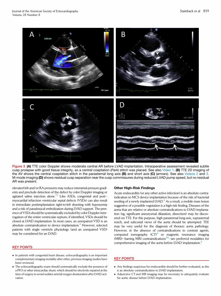
Figure 3 (A) TTE color Doppler shows moderate central AR before LVAD implantation. Intraoperative assessment revealed subtlecusp prolapse with good tissue integrity, so a central coaptation (Park) stitch was placed. See also Video 1. (B) TTE 2D imaging ofthe AV shows the central coaptation stitch in the parasternal long axis (B) and short axis (C) (arrows). See also Videos 2 and 3.M-mode imaging (D) shows residual cusp separation near the cusp commissures during reduced LVAD pump speed, but no residualAR was present.
Journal of the American Society of EchocardiographyVolume 28 Number 8
Stainback et al 859
elevated left and/or RA pressures may reduce interatrial pressure gradi-ents and preclude detection of the defect by color Doppler imaging oragitated saline injection alone.39 Like ASDs, congenital and post–myocardial infarction ventricular septal defects (VSDs) can also resultin immediate postimplantation right-to-left shunting with hypoxemiaand a risk of paradoxical embolization during LVAD support. The pres-ence ofVSDs shouldbe systematically excludedby colorDoppler inter-rogation of the entire ventricular septum; if identified, VSDs should beclosed at LVAD implantation. In most cases, an unrepaired VSD is anabsolute contraindication to device implantation.4 However, selectedpatients with single ventricle physiology (and an unrepaired VSD)may be considered for an LVAD.
KEY POINTS
� In patients with congenital heart disease, echocardiography is an importantcomplementary imaging modality after other, previous imaging studies havebeen reviewed.
� The echocardiography exam should systematically exclude the presence ofa PFO or other intracardiac shunt, which should be electively repaired at thetime of surgery to avoid sudden arterial oxygen desaturation after LVAD acti-vation.
Other High-Risk Findings
Acute endocarditis (or any other active infection) is an absolute contra-indication to MCS-device implantation because of the risk of bacterialseeding of a newly implanted LVAD.4 As a result, a mobile mass lesionsuggestive of a possible vegetation is a high-risk finding. Diseases of theaorta that are relative or absolute contraindications to LVAD implanta-tion (eg, significant aneurysmal dilatation, dissection) may be discov-ered on TTE. For this purpose, high parasternal long-axis, suprasternalnotch, and subcostal views of the aorta should be attempted. TEEmay be very useful for the diagnosis of thoracic aorta pathology.However, in the absence of contraindications to contrast agents,computed tomography (CT)4 or magnetic resonance imaging(MRI)—barring MRI contraindications40—are preferred modalities forcomprehensive imaging of the aorta before LVAD implantation.4
KEY POINTS
� Any findings suspicious for endocarditis should be further evaluated, as thisis an absolute contraindication to LVAD implantation.
� Adjunctive CT and MR imaging may be necessary to adequately evaluatefor aortic disease before LVAD implantation.

860 Stainback et al Journal of the American Society of EchocardiographyAugust 2015
PERIOPERATIVE TRANSESOPHAGEAL
ECHOCARDIOGRAPHY
Preimplantation TEE
Comprehensive perioperative TEE should be performed in the oper-ating room before LVAD implantation, with additional imaging per-formed at the time of LVAD activation and after a period ofstabilization. Preimplantation TEE is particularly important when ur-gent or emergent LVAD placement is required, in which case thismodality may serve as the primary screening echocardiographyexamination. Previous guidelines describe the recommendedapproach for perioperative TEE41,42 A comprehensive; checklist-based pre- and postimplantation perioperative TEE protocol with no-tation of red-flag findings is included in Appendix C. The physicianperforming the examination should be a highly trained cardiologistwith significant advanced TEE and perioperative TEE experience42,43
or a cardiovascular anesthesiologist with advanced perioperativeTEE training.42,44,45 Among the most important aspects ofpreimplantation TEE are reevaluation of the degree of AR,determination of the presence or absence of a cardiac-level shunt,identification of intracardiac thrombi, assessment of RV function,and evaluation of the degree of TR. These and potentially otherimportant conditions (eg, degree of MS, PR, prosthetic dysfunction,possible vegetations, aortic disease, etc.) may have been undiagnosedor underappreciated on previous imaging exams or may have pro-gressed in the intervening time. Their presence may necessitate con-version of a planned ‘‘off-pump’’ case into one that requires CPB, achange from a limited thoracotomy to a sternotomy to enable neededrepairs, or possibly biventricular MCS.
For the same reasons discussed above for TTE, the degree of AR onperioperative TEEmay be underappreciated on color Doppler imagingduring general anesthesia, because low mean arterial pressure and/orsystemic vascular resistance may be present. As a result, adequate ARassessmentmay necessitate systemic blood pressure (BP) augmentationby vasopressor agents.4 With regard to PFO detection, thorough colorDoppler scanning of the fossa ovalis margins at a low Nyquist-limitsetting and IV injection of agitated saline may be inconclusive. In thesecases, IV injection of agitated saline combined with a ‘‘ventilator’’Valsalvamaneuvermay also be useful. Thismaneuver involves injectingagitated saline into a central IV line (eg, internal jugular) during a brieflysustained application of up to 30 cmH2Oof intrathoracic pressure and,on opacification of the right atrium, release of the intrathoracic pres-sure.46 Even with this maneuver, in some cases, significant competitiveinferior vena cava ’’negative contrast’’ flow in the fossa ovalis region cancause a false-negative PFO evaluation after saline injection into the su-perior vena cava. Injection of agitated saline into a femoral vein may in-crease PFOdetection47,48 if such access is available. Despite all efforts, aPFOmay not become apparent in some cases untilMCS is initiated andthe left atrial pressure is decreased.
KEY POINTS
� The preimplant perioperative TEE is an important confirmatory imagingstudy, which can identify previously underappreciated or undiagnosed path-ologic conditions that may influence the surgical procedure.
� An LVAD perioperative TEE checklist can be useful for laboratory personnel(see Appendix C).
� Preimplantation TEE should include reevaluation of AR, RV function, TR,and the aorta. Cardiac-level shunts and intracardiac thrombi should beexcluded.
� Evaluation for PFO may require special imaging maneuvers as outlined inthe text. Despite best efforts, a PFO may not be able to be diagnosed priorto LVAD implantation.
Perioperative TEE During LVAD Implantation
Both the HM-II and the HVAD require coring in the region of the LVapex for inflow-cannula insertion. This part of the procedure is inev-itably accompanied by some degree of entrained air on the left side ofthe heart. Subsequent de-airing maneuvers require continuous TEEguidance.4 The left atrium, left ventricle (including the LV apex andinflow cannula (Figures 4 and 5), aortic root, ascending aorta,outflow graft-to-ascending aorta anastomosis (Figure 6), and trans-verse and descending aorta should all be directly visualized and care-fully inspected for signs of air.39 The ostium of the right coronaryartery (RCA) is situated anteriorly in the aortic root and is a commondestination for air ejected from the left ventricle.4 Acute RV dysfunc-tion or dilatation and/or an increase in the severity of TR should sug-gest the possibility of air embolization to the RCA, and thiscomplicationmay resolvewith watchful waiting. As during the LV cor-ing procedure, the period immediately after separation from cardio-pulmonary bypass and reinstitution of mechanical ventilation canbe accompanied by the sudden appearance of new air bubbles orig-inating from the pulmonary veins, left atrium, or left ventricle. Thisfinding, if associated with signs of RV dysfunction from a presumedcoronary air embolism, may signal the need for reinstitution of CPBand/or repeat de-airing maneuvers.4
Perioperative TEE During Initial LVAD Activation andSpeed Optimization
Upon LVAD activation, the device name and the initial pumpspeed should be annotated on the imaging screen. Although theexact order of perioperative TEE views obtained after LVAD initiationmay vary among centers, it is recommended that physicians follow anLVAD checklist-based protocol (Appendix C) to include all of theimportant components unique to postoperative LVAD assessment.Table 2 lists possible abnormal findings detectable by echocardiogra-phy after LVAD implantation. Early imaging of the interatrial septumwith color Doppler and with IV injection of agitated saline contrast toconfirm the absence of an atrial septal communication is recom-mended. This is particularly important if initiation of LVAD supportresults in a sudden decrease in arterial oxygen saturation, the hallmarkof an ‘‘unmasked’’ PFO or other right-to-left shunt (Figure 7). Next, thedegree of AV opening and the degree of AR (if any) should be as-sessed. When there is no AVopening, this may be apparent with stan-dard planar imaging. In many cases, the extent and duration of aorticcusp separation may be markedly reduced or only intermittent, de-pending upon the degree of LVAD support (pump speed). M-modeimaging of the AV in the long-axis view can be helpful for measuringand reporting the degree of AVopening (Figure 8).When there is min-imal residual native LVOT forward flow, AVopening may be intermit-tent due to pulsus alternans in regular sinus rhythm or because ofarrhythmias. A slowM-mode sweep speed (eg, 25mm/sec to acquiremore cardiac cycles) may be needed to adequately display intermit-tent AVopening (Figure 8C-E).
Aortic Regurgitation. A pump speed–dependent reduction in LVdiastolic filling pressures and increased central aortic BP can lead tothe appearance of more prominent AR on color Doppler imagingthan was appreciated before pump implantation (Figure 9A). During

Figure 4 After LVAD implantation, TEE reveals a typical unobstructed inlet-cannula position (arrow) by means of simultaneousorthogonal-plane 2D (A) and real-time 3D imaging (B). See also Video 4. The relative RV to LV size appears normal. The right ventriclehas a pacing lead.
Figure 5 (A) After LVAD implantation, TEE shows that the inflow cannula is somewhat directed towards the ventricular septum(arrow). This can be acceptable but may predispose to inflow-cannula obstruction after sternal closure or later reduction in LVsize. However, cannula position and flow velocities are shown to be acceptable (normal) in this case. Simultaneous orthogonal planeimaging reveals unobstructed, laminar inflow-cannula flow on 2D and color-flow Doppler (blue) examination. See also Video 5. (B)Pulsed Doppler interrogation of the inflow cannula shows a typical continuous, systolic dominant inflow pattern. Dashed arrow =peak systolic velocity; X = nadir diastolic velocity. (C)Continuous-wave spectral Doppler interrogation of the inflow cannula (to screenfor inflow obstruction) shows normal inflow-cannula systolic flow (black arrow); ‘‘+’’ indicates a hybrid signal that results from over-lapping of continuous diastolic inflow-cannula flow and diastolic MV inflow; ‘‘*’’ indicates MR velocity.
Journal of the American Society of EchocardiographyVolume 28 Number 8
Stainback et al 861
LVAD support, AR can be intermittent (depending upon the valveopening duration), predominantly diastolic, nearly continuous (extend-ing into the normal systolic phase of the cardiac cycle), or continuous(holosystolic and holodiastolic). Measuring the temporal occurrenceof AR can be achieved with color M-mode and continuous-wave(CW) Doppler (see Figure 9F-G). The AR duration, AR vena contracta(VC) width, LVOTAR jet height, and other evidence of hemodynami-cally significant AR (discussed in further detail, below) should guide theneed for possible surgical intervention on the AV. Although the ARVCwidth may be useful in a qualitative sense, during LVAD support, thewidth may vary throughout the cardiac cycle with continuous AR(Figure 9C) and at different pump speeds (Figure 9D,E). Methods forassessing AR severity in the context of an LVAD problem-focusedexam are further discussed below. However, in keeping with previousguideline recommendations, a VC width of $0.3 cm or a jet width/LVOT width of >46% at a Nyquist limit of 50-60 cm/s32 should be
considered to indicate at least moderate (and possibly severe) AR,owing to the prolonged (if not continuous) duration of AR duringLVAD support. Neither the AR pressure half-time method nor pulsedDoppler evaluation of aortic diastolic flow reversal is a reliable methodfor AR severity assessment after LVAD implantation. This is because theAR duration extends into the systolic ejection period. In addition, bothof these methods are highly affected by LV preload, LV afterload, andaortic pulse pressure, which is diminished during LVAD support.However, CW spectral Doppler imaginingmay be useful for evaluatingthe timing and duration ofAR (Figure 9F,G), and it’s pixel intensitymaybe additive to the qualitative assessment.
RV Dysfunction. Poor RV performance, with or without significantTR, immediately after LVAD initiation is not uncommon due to rapidnormalization of the RV preload by the pump. Early RV dysfunctionmay be transient, due to CPB-related factors, or refractory, due to

Figure 6 TEE of the outflow graft-to-ascending aorta anastomosis. (A) Simultaneous orthogonal plane 2D imaging with color-flowDoppler shows normal laminar color Doppler inflow. See also Video 6. (B) Pulsed Doppler profile (peak velocity approximately100 cm/s, dotted line). (C) Continuous-wave Doppler with a peak systolic velocity (dotted line) that, as expected, is somewhat higher(just >100 cm/s) than that revealed by pulsed Doppler. The solid line indicates the nadir diastolic velocity. (D) Typical circular appear-ance of unobstructed outflow graft-to-aorta anastomosis (arrow) using real-time 3D TEE, en face view.
862 Stainback et al Journal of the American Society of EchocardiographyAugust 2015
underlying RV dysfunction. In this setting, significant TRmay be presentdespite an ‘‘optimal’’ LVAD pump speed. However, an excessive LVADpump speed may precipitate acute severe RV dysfunction with acutesevere TR.When the LVADpump speed is set too high, the left ventriclemay become small (‘‘sucked down’’ or ‘‘over-decompressed’’), resultingin an abnormal RV-to-LV septal shift that causes distortion of the RV ge-ometry, including the tricuspid valve annulus; this alteration precipitatesor worsens TR, which, in turn, causes or exacerbates RV dysfunction.The cascade of events resulting from an excessive LVAD pump speedmay ultimately result in a ‘‘suction event,’’ a condition in which asegment of the LV myocardium partially occludes the inflow cannulaand reduces pump inflow. Suction events, along with the noted high-risk findings, can be quickly corrected by lowering the pump speed(Figure 10). Suction events can be related to other causes of reducedLVpreload relative to thepump speed setting.Accordingly, rapid assess-ment of AVopening, the relative LVand RV sizes, degree of TR, ventric-
ular septal position, inflow-cannula position, and flow velocities isrecommended after initiation of LVAD support and after changes inthe LVAD pump speed. It is important that the updated pump speedis always reannotated on the screen during the course of the perioper-ative TEE exam. A suction event that occurs at a relatively low pumpspeed or ongoing severe RV dysfunction at low levels of LVAD supportis an ominous sign that may indicate the need for a return to CPB or forbiventricular support. Suction events can be related to other causes of areduced LV preload (eg, hypovolemia) or a low afterload (eg, sepsis)relative to the pump speed setting.
Inflow Cannula and Outflow Graft. Inflow Cannula.–An appro-priately positioned inflow cannula lies near or within the LVapex and isdirected towards theMV, although someangulation towards the ventric-ular septummay be observed (Figure 5). Assessment of the relationshipof the inflowcannula to the ventricular septum is generally performedby

Table 2 Continuous-flow LVAD postimplant complications and device dysfunction detected by echocardiography
Pericardial effusion
With or without cardiac tamponade including RV compression. Tamponade: respirophasic flow changes; poor RVOT SV.
LV failure secondary to partial LV unloading
(by serial exam comparison)
a. 2D/3D: increasing LV size by linear or volume measurements; increased AV opening duration, increased left atrial volume.
b. Doppler: increased mitral inflow peak E-wave diastolic velocity, increased E/A and E/e0 ratio, decreased deceleration time of mitral E velocity,worsening functional MR, and elevated pulmonary artery systolic pressure.
RV failure
a. 2D: increased RV size, decreased RV systolic function, high RAP (dilated IVC/leftward atrial septal shift), leftward deviation of ventricularseptum.
b. Doppler: increased TR severity, reduced RVOT SV, reduced LVAD inflow cannula and/or outflow-graft velocities ( ie, <0.5 m/sec with severe
failure); inflow-cannula high velocities if associated with a suction event. Note: a ‘‘too-high’’ LVAD pump speed may contribute to RV failure by
increasing TR (septal shift) and/or by increasing RV preload.
Inadequate LV filling or excessive LV unloading
Small LV dimensions (typically <3 cm and/ormarked deviation of interventricular septum towards LV). Note: May be due to RV failure and/or pump
speed too high for loading conditions.
LVAD suction with induced ventricular ectopy
Underfilled LV and mechanical impact of inflow cannula with LV endocardium, typically septum, resolves with speed turndown.
LVAD-related continuous aortic insufficiency
Clinically significant—at least moderate and possibly severe—characterized by an AR proximal jet-to-LVOT height ratio >46%, or AR vena
contracta $3 mm; increased LV size and relatively decreased RVOT SV despite normal/increased inflow cannula and/or outflow graft flows.
LVAD-related mitral regurgitation
a. Primary: inflow cannula interference with mitral apparatus.
b. Secondary: MR-functional, related to partial LV unloading/persistent heart failure.
Note: Elements of both a and b may be present.
Intracardiac thrombus
Including right and left atrial, LV apical, and aortic root thrombus
Inflow-cannula abnormality
a. 2D/3D: small or crowded inflow zone with or without evidence of localized obstructive muscle trabeculation, adjacent MV apparatus orthrombus; malpositioned inflow cannula.
b. High-velocity color or spectral Doppler at inflow orifice. Results from malposition, suction event/other inflow obstruction: aliased color-flow
Doppler, CW Doppler velocity >1.5 m/s.c. Low-velocity inflow (markedly reduced peak systolic and nadir diastolic velocities) may indicate internal inflow-cannula thrombosis or more
distal obstruction within the system. Doppler flow velocity profile may appear relatively ‘‘continuous’’ (decreased phasic /pulsatile pattern).
Outflow-graft abnormality
Typically due to obstruction/pump cessation.a. 2D/3D imaging: visible kink or thrombus (infrequently seen).
b. Doppler: peak outflow-graft velocity$2m/s* if near obstruction site; however, diminshed or absent spectral Doppler signal if sample volume is
remote from obstruction location, combined with lack of RVOT SV change and/or expected LV-dimension change with pump-speed changes.
Hypertensive emergency
New reduced/minimal AV opening relative to baseline exam at normal BP, especially if associatedwith new/worsened LV dilatation and worsening
MR. Note: hypertension may follow an increase in pump speed.
Pump malfunction/pump arrest:
a. Reduced inflow-cannula or outflow-graft flow velocities on color and spectral Doppler or, with pump arrest, shows diastolic flow reversal.
b. Signs of worsening HF: including dilated LV, worseningMR, worsened TR, and/or increased TR velocity; attenuated speed-change responses:
decrease or absence of expected changes in LV linear dimension, AV opening duration, and RVOT SV with increased or decreased pumpspeeds; for HVAD, loss of inflow-cannula Doppler artifact.
2D, Two-dimensional; 3D, three-dimensional; A,mitral valve late peak diastolic velocity; AR, aortic regurgitation; AV, aortic valve; BP, blood pres-sure;CW, continuous-wave; E,mitral valve early peak diastolic velocity; e0,mitral annular velocity;HVAD,HeartWare ventricular assist device; IVC,
inferior vena cava; LV, left ventricular; LVAD, left ventricular assist device; LVOT, left ventricular outflow tract; MR,mitral regurgitation; MV,mitral
valve; RAP, right atrial pressure;RV, right ventricular; RVOT, right ventricular outflow tract; SV, stroke volume; TR, tricuspid regurgitation. Adopted
and modified from Estep et al.65
*Note: based on observational data. The ‘‘normal’’ outflow graft peak velocities are not well defined. Because the HVAD outflow graft diameter is
smaller than that of theHM II device (see discussion in text). Therefore, the normal Doppler-derivedHVADoutflow velocitiesmay be somewhat higher
on average than those observed for the HM II LVAD.
Journal of the American Society of EchocardiographyVolume 28 Number 8
Stainback et al 863

Figure 7 Perioperative TEE showingmarked RA-to-LA shuntingvia an ‘‘unmasked’’ PFO, which became apparent immediatelyafter LVAD activation. The PFO ‘‘tunnel’’-defect shunt is readilyapparent on color-flow Doppler (arrow) with a low Nyquist-limitsetting of 30 cm/s. See also Video 7.
864 Stainback et al Journal of the American Society of EchocardiographyAugust 2015
using standard planar mid-esophageal LV views.39 Additional simulta-neous orthogonal planes and real-time 3D imaging may be used to bet-ter identify the terminal portion of the cannula within the LV cavity(Figures 4A,B and 5A). Although a certain degree of inflow-cannula de-viation towards the interventricular septum may be unavoidable, anexcessive degree of angulation may necessitate surgical revision, givenan expected decrease in LV cavity size either acutely or later in the clin-ical course after initiation of MCS. The combination of a smaller LV cav-ity and an angulated cannula can result in direct contact between theinflow cannula and the septum, which, in turn, can cause ventricular ar-rhythmias and/or inflow-cannula flow obstruction, as previously dis-cussed. Additionally, the inflow cannula may directly interfere withthe native submitral apparatus, and this finding should be communi-cated to the surgeon. Color Doppler interrogation of a properly alignedHM-II inflow cannula should reveal low-velocity (typically #1.5 m/sec)49 laminar, unidirectional flow from the ventricle to the inflow can-nula, with a variable degree of uniform systolic augmentation and noregurgitation (Figure 5B).39 In some cases, the normal inflow-cannulaspectral Doppler flow signal may be ‘‘contaminated’’ by mitral inflowand/or AR (Figure 5C). Using both pulsed and CW spectral Dopplerfor interrogating the HM-II inflow-cannula flow is recommended, in or-der to screen for obstructive velocities (Figure 5C). Any HM-II inflowcannula turbulent colorDoppler or significant peak systolic velocity vari-ability suggests the presence of mechanical obstruction by the interven-tricular septum, LVmuscular trabeculations, or submitral apparatus. Thepericardial location of theHVAD impeller results in a prominent, charac-teristic color and a spectral Doppler artifact that generally precludesDoppler interrogation of the inflow cannula.49,50 The HVAD Dopplerartifact occurs only when the inflow cannula appears within theimaging sector. Therefore, successful color and spectral Dopplerinterrogation of other cardiac structures is possible whenever theimaging plane excludes the HVAD inflow cannula (Figure 11).Consequently, HVAD inflow must be determined indirectly by corre-lating the inflow cannula anatomic imaging (ie, does the cannula appearunobstructed?) with downstream anatomic and hemodynamic parame-ters, as discussed in more detail below.
Outflow Graft.–After interrogation of the inflow cannula, attentionshould be directed towards the outflow graft. Whereas the proximal
outflow graft is not visible with TEE, the middle portion adjacent tothe right side of the heart (Figure 12) and the distal outflow graft-to-aorta anastomosis can be visualized in the majority of patients. Flowfrom the outflow graft into the aorta can be visualized by colorDoppler interrogation near the level of the right pulmonary artery(eg, great vessel, upper esophageal view [Figures 6 and 13]).Simultaneous orthogonal-plane or real-time 3D imaging may allowbetter characterization of the anastomosis site. Every effort shouldbe made to perform spectral Doppler interrogation coaxially to thedirection of flow. As with the inflow cannula described above, thespectral Doppler appearance should consist of low-velocity, laminar,unidirectional flow with a variable amount of systolic augmentation.However, outflow-graft-velocity benchmarks are not available. Thepeak systolic and nadir diastolic Doppler-derived velocities varywith pump speed in the same patient, and these speeds may alsovary with the graft cross-sectional area of the particular device type.However, an outflow-graft peak systolic velocity of >2 m/s at anylevel (including the that of the aortic anastomosis) may be abnormaland warrant further investigation or monitoring.
Finally, it is important to note that sternal closure can change theorientation of either the inflow cannula or the outflow graft relativeto their open chest positions. Accordingly, it is critical to reevaluatethe inflow cannula orientation and flow characteristics and theoutflow graft and/or outflow graft-to-aorta anastomosis flow immedi-ately after sternal closure. This can be accomplished by TEE or TTE.
Pump Speed. Optimal pump speed selection is a complex topic.The early postimplantation recovery phase may be associated withsignificant fluctuations in LV preload and afterload. Therefore, the im-mediate postimplantation (operating room) pump speed that is asso-ciated with ‘normal’ LVAD function by the perioperative TEEparameters discussed above may or may not be appropriate lateron. In addition (as discussed in more detail, below), selection of an‘‘optimal’’ LVAD speed setting varies among implantation centers.Some centers select the speed that minimizes LVEDVs and/or theLVIDd while allowing at least intermittent AV opening (assessedbest by M-mode echocardiography at the AV level). Other centersmaximize LV unloading, leaving the AV closed.
KEY POINTS
� Intracardiac air is a consequence of LVAD implantation, and TEE evaluationis useful for ascertaining the success of de-airing maneuvers.
� All images acquired after LVAD activation should be annotated with the de-vice name and current pump speed.
� Postimplant perioperative TEE should include rapid assessment forpossible unmasked PFO shunt, AV opening, the relative LV and RV sizes,degree of TR, ventricular septal position, inflow-cannula position, and flowvelocities after initiation of LVAD support and after changes in the LVADpump speed.
� A ‘‘suction event,’’ is a condition in which a segment of LV myocardiumpartially occludes the inflow cannula and reduces pump inflow. This compli-cation is usually related to over-pumping of the left ventricle (producing asmall ‘‘sucked down’’ LV cavity). Suction events can often be quickly cor-rected by lowering the pump speed.
� HM-II inflow cannula peak systolic flow velocities are typically <1.5 m/sec.Higher velocities suggest possible inflow-cannula obstruction.
� HVAD inflow-cannula velocities cannot be measured due to a characteristicDoppler artifact.
� TEE imaging can frequently show the anatomic contour and flow velocitiesof the distal outflow-graft region and the outflow-graft–to–aorta anasto-mosis.

Figure 8 The duration of AV opening during LVAD support can be easily measured using M-mode during either TEE (A) or TTE (B). Inview A, the AV ‘‘barely opens’’ intermittently (arrows); thismay, in part, be related to an arrhythmia and suggests normal LVAD functionat a pump speed of 9600 rpm. In view B, there is near-normal AV opening, with durations of >200ms; this may be an abnormal findingat a high LVAD pump speed (9800 rpm). (C–E) The expected progressively reduced duration of AV opening in the same patient duringa ramp (speed-change) echo examat different HM-II pump speeds: In viewC (8000 rpm), the AV ‘‘barely opens’’; in viewD (8600 rpm),the AV ‘‘opens intermittently’’ (arrows); in view E (9000 rpm), the AV ‘‘remains closed.’’
Journal of the American Society of EchocardiographyVolume 28 Number 8
Stainback et al 865
� Outflow-graft velocities of >2 m/s at any level may be abnormal and war-rant further consideration for possible obstruction, although benchmarkdata are lacking in this regard.
ROLE OF ECHOCARDIOGRAPHY (TTE OR TEE) AFTER LVAD
IMPLANTATION
The significant variability in the clinical courses of individual patientsafter LVAD implantation precludes a ‘‘one-size-fits-all’’ approach topostimplantation echocardiography. Nevertheless, the authorsbelieve that an overall framework can be recommended. In general,the starting point for any LVAD echocardiographic examination is acomprehensive ‘‘HF’’ TTE exam, which is performed at the pump’sbaseline speed setting and includes LVAD-specific views andDoppler flow assessments in addition to all the elements of preoper-ative TTE. In some cases, outlined below, the exam also includes thesystematic reacquisition of selected exam components at pumpspeeds above and/or below the baseline speed. The exact protocolfor changing pump speeds varies, depending on the indication for ex-amination. There are three subcategories of LVAD echo protocol in-dications that appear to reflect real-world clinical management:
1. LVAD surveillance echocardiography, with or without LVAD optimization echo-cardiography.
2. LVAD problem-focused echocardiography, with or without an LVAD speed-change protocol.
3. LVAD recovery echocardiography.
LVAD Surveillance Echocardiography
LVAD surveillance echocardiography is performed at the pump’s base-line speed setting and includes LVAD-specific views and Dopplerflow assessments in addition to all the elements of a standard HFTTE exam. Addition of an LVAD optimization protocol, may involvefurther limited imaging at pump speeds higher and/or lower thanthe baseline speed to optimize LVAD and native heart function.
The authors recommend that patients with an uncomplicated post-operative course (eg, absence of HF symptoms, successful weaningfrom IV pharmacologic inotropic and vasopressor agents within 14days, absence of LVAD controller alarms, and lack of serologic evi-dence of hemolysis or infection) undergo follow-up surveillanceTTE at prespecified intervals. Periodic LVAD surveillance echoexams are recommended, to establish patient-specific ‘‘baseline’’ pa-rameters for both LVAD and native heart function. An LVAD surveil-lance echo exam should be considered at approximately 2 weeksafter device implantation or before index hospitalization discharge(whichever occurs first), followed by consideration of surveillanceTTE at 1, 3, 6, and 12 months post implantation and every 6 to 12months thereafter. Figure 14 summarizes a sample schedule

Figure 9 Assessment of AR. (A) TEE shows at least moderate—and possibly severe—continuous AR during LVAD support. The ARVC is clearly >3 mm, and the jet width/LVOT width is clearly >46%. Color-flow Doppler reveals inflow-cannula systolic entrainment ofthe AR jet (arrow). A closed MV and trace MR (*) are indicative of marked systolic AR. RVOT, right ventricular outflow tract. See alsoVideo 8. (B, C) During LVAD support, at least moderate continuous AR (arrow) is observed in the transthoracic parasternal long-axisviewwith color Doppler (B) and colorM-mode imaging (C); the inflow cannula is denoted by an asterisk. In viewC, note the variance inthe early systolic (arrowhead) versus late systolic (arrow) AR VC width, as shown by M-mode. This finding is not consistent amongdifferent patients; it is likely influenced by several variables and by the fact that the AV cusps can exhibit augmented systolic opening,despite AR, at speeds close to (but below) the AV ‘‘opening speed.’’ See also Video 9. (D–E) The AR VC width may increase at higherpump speeds in the same patient, as seen here. This may partially be due to an increased systemic arterial pressure at higher pumpspeeds, which presumably increases the AR volume. At both speeds, the VC is >3 mm, indicating at least moderate—and possiblysevere—AR. The VC width is 4.2 mm at 8600 rpm in view D and is 5.7 cm at 9600 rpm in view E (HM-II LVAD). (F) ‘‘Continuous’’ hol-osystolic and holodiastolic AR, as detected by continuous-wave Doppler (TTE apical 5-chamber view). (G)Continuous-wave Doppler(TTE apical 5-chamber view) reveals nearly continuous AR, which significantly extends into the electrical and mechanical systolicperiod with a brief period of AV systolic forward flow (arrows). (H) Color M-mode shows minimal AV opening, with a brief durationof low-velocity systolic forward flow (arrows). (I) TTE parasternal long-axis view of an AR jet on color-flow Doppler imaging (arrow).(J) The AV opens widely, with forward flow that interrupts AR. However, the AR period extends into the electrical and mechanicalsystolic period (arrows) during HVAD pumping at 2600 rpm.
866 Stainback et al Journal of the American Society of EchocardiographyAugust 2015
for timing postimplantation surveillance TTE. Comparison of serialsurveillance-exam results to each other (for an individual patient) orto population-based benchmarks (see Appendix D) can also helpthe examiner understand a patient’s response to LVAD therapyover time. Moreover, surveillance data may allow early diagnosis ofoccult native heart abnormalities (eg, development of LVAD-relatedAR) or other device-related problems, including a drift from previ-ously optimal device speed settings. When surveillance TTE is coordi-nated with the patient’s routine LVAD clinic visits, HF specialists canintegrate the information obtained into their clinical assessmentsand care plans. A putative benefit of routine LVAD surveillance echo-cardiograms (with optimization protocols when indicated) isimproved patient outcomes, including early detection and treatmentof complications and reduced hospitalizations for recurrent HF.
KEY POINTS
� Patients with an uncomplicated postoperative course should undergo LVADsurveillance echocardiography at certain predetermined intervals afterLVAD implantation to assess the patients’ response to MCS therapy andto screen for the development of subclinical complications.
� When possible, LVAD surveillance echocardiography should be coordinatedwith routine LVAD-clinic visits.
Clinical Data-Acquisition Standards and Sonographer
Reproducibility (see Table 3). Before initiating any LVAD echoexam, sonographers should always annotate the LVAD type and base-
line LVAD speeds in rotations per minute (rpm) on the imaging screenin addition to the standard patient demographic data. If the devicespeed is changed, this should be reannotated during the exam. Thedevice type and speed information should also be routinely incorpo-rated into reporting templates.
Blood Pressure. The patient’s BP, which reflects peripheralvascular resistance, is an important parameter that greatly influencesventricular unloading and the observed echocardiographic findings.Therefore, the BP should be recorded just before the exam andimmediately afterward if pump speed changes were made. Patientswith CF-LVADs have a reduced and narrowed pulse pressure, and apalpable pulse may be absent. Therefore, cuff-based BP assessmentmay be difficult or impossible to perform. In the intensive care unit,the BP may be obtained from invasive arterial monitoring devices.In other settings in which no pulse is present, the use of a BP cuff alongwith handheld audible Doppler evaluation of the brachial or radial ar-tery may be required.51 Note that the arterial Doppler-derived BPreading lies between the systolic pressure and the mean arterialBP.52 For practical purposes, if the patient has a pulse (ie, the AV isopening), the Doppler-derived BP is the same as the systolic BP. Ifthe patient does not have a pulse (ie, the AV is not opening), theDoppler BP is considered to be the mean arterial BP. A current BPmeasurement is necessary for accurate echo interpretation and forsafety reasons during ‘‘speed change’’ protocols, particularly whenchanging to higher speed settings. Susceptible patients may developclinically significant hypertension in response to increased LVADflow, and a mean arterial pressure of <85 mmHg is recommended.53

Figure 9 (continued).
Journal of the American Society of EchocardiographyVolume 28 Number 8
Stainback et al 867
Hypotension is generally defined as a mean arterial pressure of <60mmHg andmay be associated with traditional symptoms and/or signsreflective of hypoperfusion. With CF-LVADs, one of the challenges isthat a sonographer (or some other trained and available individual)needs to be facile at obtaining an arterial Doppler-derived BP reading.To facilitate the care of CF-LVAD recipients, there may be a need forimproved BP monitoring techniques.54
KEY POINTS
� Although BP readings can be challenging to obtain in LVAD patients, thisvariable is important, as it significantly influences observed echo findingsand their interpretation.
� In the absence of a palpable pulse, BP measurement may require audibleDoppler interrogation by an appropriately trained individual before theecho exam.
� Susceptible patients can experience marked hypertension after the LVADpump speed is increased. Therefore, the BP measurement should berepeated after a significant pump-speed increase, particularly if the BP iselevated at the baseline pump speed.
� A mean arterial BP of <85 mm Hg is recommended.� Hypotension is generally defined as a mean arterial pressure <60 mmHg. Itmay be associated with traditional symptoms and/or signs of hypoperfusion.
LV Size and Systolic Function. Methods for determining LV sizeand systolic function by using linear and volumetric approaches innon-LVAD patients have been described by Lang and colleagues.17
LV Size.–As mentioned above, the LVIDd from the 2D parasternallong-axis image is considered the most reproduciblemeasure of LV size
after LVAD implantation (Figure 15A). In the presence of a normallyfunctioning CF-LVAD, severely depressed native LV function, andaltered MV opening, determination of end-diastole may be difficult.In this scenario, correlating the images to the electrocardiographic signalcan be helpful. Additionally, strong consideration should be given to theuse of a microbubble contrast agent when endocardial definition isinsufficient for accurate LVIDd measurement.20 Previous data fromHM-II outpatients in stable condition suggest that at least a 15% reduc-tion in the LVIDd compared to preimplant values can be expected 3months after implantation.55,56 Care must be taken to correlate LVend-systolic versus end-diastolic diameters with the electrocardio-graphic signal. The LVIDd may be paradoxically smaller than theLVIDs, and this is an important finding, as it is associated with excessiveLVAD unloading and/or severe RV dysfunction. Although LV volumes,as determined by Simpson’s biplane or single-planemethod (Figure 16),reflect the LV sizemore accurately than do linearmeasurements, the LVsize by volume assessment may be technically challenging to obtainafter LVAD implantation because of apical shadowing/dropout associ-ated with the inflow cannula. This is one reason why postimplantationLV volumes assessed by echocardiography are smaller than those as-sessed by CCT.57 A reasonable LV diastolic volume assessment ispossible in many ambulatory LVAD patients, and this metric can beincorporated into the surveillance exam, particularly at the baselinepump speed setting. However, LVIDdmeasurement, beingmore expe-diently acquired and reproducible, is practical for tracking the relativeLV size over time at a baseline pump speed (eg, Figure 15A vs. 15B)and in the context of a speed-change exam (see below) for quick prob-lem solving. That the serial LVIDd measurement (combined with thedegree of AVopening) can be used as a surrogatemarker for the degreeof LV unloading in CF-LVAD patients seems intuitive and is supportedby limited available literature, which is derived primarily from HM-II

Figure 10 Suction event diagnosed with perioperative/postoperative TEE soon after HVAD activation. A 2400-rpm pump speed wasinitially satisfactory until the patient developed sudden hypotension and LVAD flow cessation. (A) Relook imaging (mid-esophageal 2-chamber view) showed LV cavity obliteration (dotted line) and inflow-cannula obstruction by the anterior LV endocardium (arrow). Seealso Video 10. (B) Restoration of acceptable LV size and normalized LVAD function seconds after pump-speed reduction to 2200rpm. Note: In this case, the suction event was precipitated by intravascular volume depletion and a low afterload following weaningfrom CPB; the event was easily corrected by reducing the pump speed, administering IV fluids, and adjusting vasopressor infusions.In this example, the RV remained small and not dilated. However, CPB suction events can result from a low LV preload related toacute RV failure, with associated RV dilatation, TR, and a leftward ventricular septal shift that may persist despite pump-speed reduc-tion (see the TTE example below). Depending on the degree of underlying RV dysfunction, perioperative suction events or RV failuremay or may not be transient and responsive to medical management. See also Video 11.
868 Stainback et al Journal of the American Society of EchocardiographyAugust 2015
studies. However, robust outcomes data are limited, and applicability toHVAD patients, for whom there is less evidence, has not been demon-strated at this time.58
LV Systolic Function.–Accurate determination of LV volumes is chal-lenging after device implantation. So, too, is accurate and meaningfuldetermination of overall LV systolic function, as based on the LVEF.Limitations for LVEF measurements are both technical with regardsto imaging quality (endocardial border detection) and physiologic.The LVendocardiummay be difficult to visualize because of apical fore-shortening, apical shadowing from the device or acoustic dropout(signal attenuation). LVAD-related physiologic challenges includeenhanced interventricular dependence and discordant septal and in-ferolateral wall motion, which may vary considerably in the same pa-tient at different pump speeds. If the LV endocardium, including theapex, can be adequately visualized, with or without a microbubblecontrast agent, the preferred method for calculating the LVEF is thebiplane method of disks (Figure 16), modified Simpson rule).17
Although other parameters for LV systolic functionmay be considered,the LVEF is an important surrogate for showing possible LV worseningor recovery. Therefore, surveillance and recovery LVAD exam reportsshould include an LVEF assessment, even if only a qualitative assess-ment is possible. However, LVAD support markedly reduces LVpreload, an important determinate of LVEF. Therefore, the value ofLVEF for determining systolic function during LVAD support must betaken into consideration during clinical decision-making.
Other methods: In patients with suboptimal apical but adequate par-asternal views, the following methods for measuring LV systolic func-tion may be considered, although their accuracy has not beenvalidated in LVAD patients.
1. The LV fractional area change (FAC) method at the mid-papillary musclelevel on 2D short-axis views: FAC (%) = [(end-diastolic area - end-systolicarea)/(end-diastolic area)].59
2. The Quinones method for determining the LVEF,60 with the assumption ofan akinetic apex given the presence of the apical inflow cannula.
3. The LV fractional shortening (%) method: FS = [(LVIDd-LVIDs)/(LVIDd)],where FS = fractional shortening and LVIDs = the LV internal dimension atend-systole,17 which has been applied in LVAD patients.57,61
The linear and volume measurements of systolic function notedabove represent possible methods for tracking the course of individ-ual patients, serving as their own controls, over time. However,routine use of methods 1 to 3, above may not be feasible or recom-mended for many LVAD patients because of segmental wall-motionabnormalities, exaggerated paradoxical septal motion, ventricular dys-synergy and/or ventricular septal shift, the extent of which couldchange at varying pump speeds in the same patient. Note thatmethods of calculating the LVEF based on the LV stroke volumeare not recommended, because many LVAD patients have beat-to-beat variations in this parameter.49 Previous data suggest that thevast majority of outpatient HM-II recipients in stable condition havepersistent moderately to severely depressed LV systolic function dur-ing the first 6 months after device implantation.55,56
KEY POINTS
� After CF-LVAD activation, the LVIDd may be the most reproducible mea-sure of LV unloading that can be tracked over time and/or at differentpump speeds.
� The LVEDV is a more accurate representation of LV size than is the LVIDd.� After LVAD implantation, measurement of LV volumes and the LVEF can betechnically challenging.When the LVEF needs to be obtained (particularly toassess for LV recovery), Simpson’s biplane method of disks is recommendedfor use when possible.
LV Diastolic Function. It is assumed that LVAD patients havemarkedly abnormal baseline diastolic function. Although the standardLV diastolic function parameters62 can be measured and included inthe report, there is a paucity of data validating their clinical usefulnessin the setting of LVAD support. The use of certain diastolic parameters

Figure 11 An HVAD inflow-cannula Doppler exam is typically not possible due to the characteristic color artifacts (A) (**) and spec-tral Doppler artifacts (B). See also Video 12. When the inflow cannula is excluded from the 2D imaging sector (C), the artifactsdiminish, and other aspects of the Doppler exam can be performed. (D) Successful continuous-wave Doppler examination ofMR in the same patient after slight rotation of the imaging sector away from the inflow cannula. Because the 2D image (viewA: arrow) suggests that the inflow cannula is directed towards the ventricular septum, normal inflow-cannula flow must beconfirmed by other methods, whether TEE or TTE. See also Video 13.
Journal of the American Society of EchocardiographyVolume 28 Number 8
Stainback et al 869
could be helpful, particularly when correlated with symptoms in indi-vidual patients, and at the discretion of the interpreter since they mayreflect changes in the degree of LV unloading when compared to aprior study’s data or at different pump speeds during the sameexam. Previous data suggest that the mitral E velocity (cm/s), left atrialvolume (mL), pulmonary vascular resistance (Wood units), and pul-monary artery systolic pressure (mmHg) are significantly reducedand that the mitral deceleration time (ms) is significantly prolongedin outpatients whose condition is stable 3 to 6 months after HM-II im-plantation.55,56 How these parameters should be integrated intopostimplantation clinical management is currently undefined, as istheir prognostic value for patient outcomes. For a clinical LVADecho reporting purposes, a practical approach at this time may beto use the following (or a similar) statement: ‘‘Interpretation of thedegree of LV diastolic dysfunction (presumed abnormal) is notprovided because of continuous flow LVAD support.’’
KEY POINTS
� It may be assumed that LVAD patients have markedly abnormal baselinediastolic function.
� How LV diastolic parameters measured after LVAD implantation should beintegrated into the echocardiography interpretation and clinical manage-ment is currently undefined, as is their prognostic value for patient out-comes.
RV Size and Systolic Function. Many of the standard measuresof RV size and systolic function,22 including linear dimensions, RVFAC, TAPSE, and right-sided cardiac output, can feasibly be measuredin LVAD patients.56,63,64 However, recent data suggest that thecorrelation of TAPSE with overall RV systolic function may beweaker after cardiothoracic surgery and, therefore, this variable mayhave less clinical utility than the other measures.65 Current dataregarding the expected response of RV systolic function after LVADimplantation are conflicting: one study showed a significant improve-ment in RV FAC at 3 months,55 but another study did not show a sig-nificant difference in this parameter at either 1 month or 6 months.56
Valvular Assessment. Aortic Valve.–Evaluating and reporting thedegree of AV opening (if any) is important because it is affected by anumber of other parameters, includingLVADspeed, native LV function,volume status, and peripheral vascular resistance. In addition, whetheror not the AV opens may have clinical implications. Whereas recentguidelines recommend that the LVADspeed be set low enough to allow

Figure 12 LVAD outflow graft, as assessed by TEE. (A,B) In a modified mid-esophageal 4-chamber view (A), the outflow graft (*) isfrequently seen in near short-axis orientation. See also Video 14. (B) Shows the utility of simultaneous orthogonal-plane imaging,which, in this case, a short axis image of the outflow graft (single arrow) is used as a reference image to reveal a long segment ofthe graft overlying the RA in a standard bicaval view (double arrows). See also Video 15. (C) Successful pulsed Doppler interrogationof the outflow graft (this is not always possible in practice). See also Video 16.
Figure 13 TEE characteristics of severe AR due to aortic cusp fusion associatedwith longstanding LVAD support. (A)Mural thrombuswithin the AV noncoronary cusp (arrow). See also Video 17. (B) Severe AR, as detected by color-flow Doppler. See also Video 18. (C)Using the right pulmonary artery (rPA) as an acoustic window, an upper esophageal long-axis view of the ascending aorta (Ao) showsthe LVAD outflow graft (arrow) and its ascending aortic anastomosis site (*). (D) Color-flow Doppler evaluation of the outflow- graft–aorta anastomosis. See also Video 19. (E) Pulsed Doppler assessment of the outflow anastomosis reveals a laminar signal with highflow characterized by nearly equal systolic (dotted line) and diastolic (solid line) velocities (arrow), consistent with severe AR.
870 Stainback et al Journal of the American Society of EchocardiographyAugust 2015
at least intermittent AVopening,4 such opening may not occur at anyLVAD speed in patients with extremely poor native LV function. Thefrequency of AVopening is most accurately assessed by recording mul-tiple (five to six) cardiac cycles at a slowM-mode sweep speed (eg, 25-50 mm/s) (Figure 8D,E); the valve should be characterized as eitheropening with every cardiac cycle, opening intermittently, or remainingclosed.49,66 Many HF teams also request that the duration of AVopening (ms) be measured from the same M-mode acquisitions. Thisparameter may vary from beat to beat, so it is best to measure severalbeats and report an average value. When the AV-opening duration isrelatively constant, a faster sweep speed (eg, 75-100 mm/s) may beappropriate (Figure 8A,B). An important potential pitfall of using M-mode to assess the presence and duration of aortic cusp separation isillustrated in Figure17. TheAV semilunar cusp conformation, combinedwith cardiac translational motion or slightly off-axis imaging, can createthe false appearance of aortic cusp separation, evenwhen the cusps arenot separating. Careful attention and the additional use of color M-mode may be useful in difficult cases to avoid M-mode ‘‘pseudo AVopening’’ or an exaggerated AV-opening duration. However, an addi-
tional interesting observation is that in some cases of ‘‘minimal’’ AVopening, the duration of AV cusp separation and duration of forwardsystolic flow are not always the same, and color M-mode can help todocument this finding (Figure 9G,H). In patients whose AV remainsclosed, it is important to evaluate for aortic root thrombus, whichmay be transient or associated with commissural fusion.Continuously closed aortic cusps have been associated with the devel-opment of aortic root thrombosis and LVAD-associated AR, as dis-cussed below.67 Fusion of the aortic cusps, either surgical orsecondary to chronic aortic cusp closure, can be recognized onspeed-change echocardiograms (discussed below).
New-onset (‘‘de novo’’) AR occurs in approximately 25% to 33%ofpatients 12 months after LVAD implantation68,69 and is a key finding,given its known adverse effects on LVADperformance,morbidity, andmortality.70-72 Several studies suggest that persistent AV closure is arisk factor for de novo AR after LVAD implantation, even withoutthe presence of aortic root thrombus (Figure 18).68,73,74 For thereasons noted above in the postimplant TEE section, standardmethods for quantifying AR32 may be challenging to use after

Figure 14 Sample schedule for initial and follow-up surveillance echocardiography of patients with no evidence of device malfunction.
Journal of the American Society of EchocardiographyVolume 28 Number 8
Stainback et al 871
LVAD implantation. In the absence of definitive cutoff criteria todefine mild, moderate, and severe AR after LVAD implantation, oneshould perform an aggregate assessment based on duration (predom-inantly diastolic vs. continuous), AR jet VCwidth, jet height relative tothe LVOT, comparative LVADand native circuit flowmeasures andLVchamber size. Additionally, significant AR noted on LVAD surveillanceechocardiography may be further evaluated with device controllerdata and the cardiac response during LVADproblem-focused echocar-diography with speed changes, as described below.
KEY POINTS
� Recording multiple cardiac cycles with color M-mode at a sweep speed of25-50 mm/s is recommended to accurately assess the frequency and dura-tion of AVopening.
� Persistent AV closure can be associated with aortic root thrombus and denovo AR.
� If aortic root thrombus is suspected, a decrease in the LVAD pump speedshould be avoided, as it could result in sudden AV opening (eg, during aplanned speed-change exam).
� After LVAD implantation, the presence of AR is not uncommon. Assess-ment of severity is partly based on careful color Doppler analysis in the para-sternal long-axis view.
Mitral Valve.–As noted above, LV unloading generally leads toreduced MV annular dilatation, improved leaflet coaptation, and, ul-timately, reducedMR severity. Persistence of significantMR after initi-ation of LVAD support may indicate inadequate LV unloading orinflow cannula malposition and interference with the submitral appa-ratus. If MR is present, it can be quantified by using standardmethods.32 Incidental post-LVAD MR may also represent LVAD mal-function and should be discussed with the clinical team.
Tricuspid and Pulmonary Valves.–Like MR, moderate or greater TRis an important finding on LVAD surveillance echocardiography, as thiscondition may be associated with insufficient LV unloading (functionalTR), excessive LV unloading with a leftward shift of the interventricularseptum (eg, a suction event), elevated systolic pulmonary pressures,and/or intrinsic RV systolic dysfunction. Distinguishing betweenthese etiologies by utilizing echocardiographic parameters is discussedin further detail below. Regardless of the etiology, TR after LVAD im-plantation can generally be assessed with standard methods.32
Furthermore, the native pulmonary valve typically remains functionallynormal after LVAD implantation and can be interrogated by using stan-dard methods when significant stenosis or regurgitation is sus-pected.32,33 As noted in the foregoing discussion of perioperativeTEE, the presence of significant preexisting or acquired PR may haveimplications with regards to RV function and/or the ability toperform RVAD implantation if needed.
Interventricular Septal Position. The end-diastolic interventric-ular septal position, which is dependent on the interventricular pres-sure gradient, should be routinely reported as neutral, leftward-shifted, orrightward-shifted. A leftward shift can be due to elevated RV end-diastolic pressures, reduced LV preload, or LVover-decompression re-sulting from excessive LVAD speed; differentiation of these etiologiesis further discussed below. A rightward shift is generally due toelevated LV end-diastolic pressures resulting from an inadequateLVAD speed setting, pump dysfunction, severe AR, or an increasedLV afterload.
Inflow-Cannula and Outflow-Graft Interrogation. Inflow
Cannula.–Usually, the apically inserted inflow cannula can beadequately imaged in standard or modified 2D parasternal and apicalTTE views. The sonographer’s objective is to reveal the inflow can-nula’s location and orientation in relation to the interventricularseptum and other LV structures. The inflow cannula can often be visu-alized with 3D echo techniques, and this approach may be used as acomplementary imaging method by examiners experienced in 3Dimaging. As noted above in the section on perioperative TEE, colorDoppler interrogation of a properly aligned inflow cannula shouldreveal laminar, unidirectional flow from the ventricle to the inflowcannula, with no evidence of turbulence or regurgitation.39 Pulsedand CW spectral Doppler interrogation may require ‘‘off-axis’’ modi-fication of a standard parasternal, apical, or short-axis TTE view toachieve true coaxial alignment between the sampling beam andinflow-cannula flow; such interrogation should additionally revealthe flow to have a low peak velocity (<1.5 m/s). Due to native LVcontractility, cannula flow generally remains pulsatile to some degreeeven when the AV does not open.49,55 Recording both the peaksystolic and nadir diastolic velocities over at least three to fourcardiac cycles is recommended (Figures 5 and 19).
The inflow cannula should be routinely interrogated with CWspectral Doppler at the baseline pump speed and particularly duringthe course of speed-change exams (discussed, below) to screen forinflow obstruction. Note that in many cases, a normal inflow-cannula spectral Doppler flow-velocity profile may be contaminatedby low-velocity diastolic AR or mitral inflow (Figure 20). Moreover, inthe setting of TEE evaluation of the inflow cannula, the CW Dopplersignal can be contaminated by MR (Figure 5C) as well. The HVADinflow-cannula flow velocities typically cannot be evaluated by usingeither color or spectral Doppler due to a characteristic Doppler arti-fact (Figure 21) related to the inflow cannula’s direct connection tothe adjacent impeller housing.
Outflow Graft.–In contrast to inflow-cannula imaging, visualizing theoutflow graft requires the utilization of atypical echocardiographicwindows. The terminal portion of the outflow conduit and its
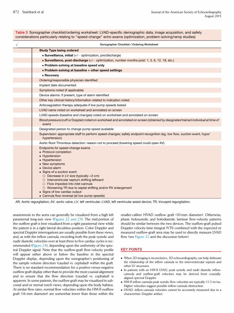
Table 3 Sonographer checklist/ordering worksheet: LVAD-specific demographic data, image acquisition, and safetyconsiderations particularly relating to ‘‘speed-change’’ echo exams (optimization, problem-solving/ramp studies)
O Sonographer Checklist / Ordering Worksheet
Study Type being ordered
� Surveillance, initial (+/� optimization, pre/discharge)
� Surveillance, post-discharge (+/� optimization, number months post: 1, 3, 6, 12, 18, etc.)
� Problem-solving at baseline speed only
� Problem-solving at baseline + other speed settings
� Recovery
Ordering/responsible physician identified
Implant date documented
Symptoms noted (if applicable)
Device alarms: if present, type of alarm identified
Other key clinical history/information related to indication noted
Anticoagulation therapy adequate if low pump speeds tested
LVAD name noted on worksheet and annotated on screen
LVAD speeds (baseline and changes) noted on worksheet and annotated on screen
Blood pressure (cuff or Doppler) noted onworksheet and annotated on screen (obtained by designated trained individual at time ofexam)
Designated person to change pump speed available
Supervision: appropriate staff to perform speed changes; safety endpoint recognition (eg, low flow, suction event, hypo/hypertension)
Aortic Root Thrombus detection: reason not to proceed (lowering speed could open AV)
Endpoints for speed-change exams� Protocol completion
� Hypotension
� Hypertension
� New symptoms� Device alarm
� Signs of a suction event
B Decrease in LV size (typically <3 cm)
B Interventricular septum shifting leftwardB Flow impeded into inlet cannula
B Worsening TR due to septal shifting and/or RV enlargement
� Signs of low cardiac output� Cannula flow reversal (at low pump speeds)
AR, Aortic regurgitation; AV, aortic valve; LV, left ventricular; LVAD, left ventricular assist device; TR, tricuspid regurgitation.
872 Stainback et al Journal of the American Society of EchocardiographyAugust 2015
anastomosis to the aorta can generally be visualized from a high leftparasternal long-axis view (Figures 22 and 23). The mid-portion ofthe outflow graft is best visualized from a right parasternal view whilethe patient is in a right lateral decubitus position. Color Doppler andspectral Doppler interrogations are usually possible from these views;and, as with the inflow cannula, recording both the peak systolic andnadir diastolic velocities over at least three to five cardiac cycles is rec-ommended (Figure 24), depending upon the uniformity of the spec-tral Doppler signal. Note that the outflow-graft flow-velocity profilewill appear either above or below the baseline in the spectralDoppler display, depending upon the sonographer’s positioning ofthe sample volume direction (caudad vs. cephalad) within the graft.There is no standard recommendation for a positive-versus-negativeoutflow graft display other than to provide themost coaxial alignmentand to ensure that the flow direction (caudad vs. cephalad) isapparent. In some patients, the outflow graft may be visualized in sub-costal and/or sternal notch views, depending upon the body habitus.At similar flow rates, normal flow velocities within the HM-II outflowgraft (16-mm diameter) are somewhat lower than those within the
smaller-caliber HVAD outflow graft (10-mm diameter). Otherwise,phasic holosystolic and holodiastolic laminar flow-velocity patternsshould be similar between the two devices. The outflow-graft pulsedDoppler velocity-time integral (VTI) combined with the expected ormeasured outflow-graft area may be used to directly measure LVADflow (see Figure 22 and the discussion below).
KEY POINTS
� When 2D imaging is inconclusive, 3D echocardiography can help delineatethe relationship of the inflow cannula to the interventricular septum andother LV structures.
� In patients with an HM-II LVAD, peak systolic and nadir diastolic inflow-cannula and outflow-graft velocities may be derived from coaxially-aligned spectral Doppler.
� HM-II inflow-cannula peak systolic flow velocities are typically <1.5 m/sec.Higher velocities suggest possible inflow-cannula obstruction.
� HVAD: inflow-cannula velocities cannot be accurately measured due to acharacteristic Doppler artifact.

Figure 15 Side-by-side comparison ofmultiple imagingmetrics in the same patient before and after HM-II LVAD impeller thrombosis.(A) LVIDd, normal LVAD; (B) increased size by LVIDd after LVAD thrombosis; (C)AVM-mode,minimal opening (107ms) during normalLVAD function; (D) markedly increased AoV opening duration (230 ms) after internal LVAD thrombosis; (E,G) Inflow-cannula color-flow (arrow) and pulsed Doppler images, respectively, during normal LVAD function (see also Video 20); (F,H) Very low velocityinflow-cannula systolic flow on color-flow (arrow) and pulsed Doppler images, respectively, with nearly absent diastolic flow (viewH) after development of impeller thrombosis; (I) RVOT pulsed Doppler VTI = 15 cm during normal LVAD function; (J) RVOT pulsedDoppler VTI = 7.9 cm after LVAD thrombosis. Inflow, inflow cannula; vel., velocity.
Journal of the American Society of EchocardiographyVolume 28 Number 8
Stainback et al 873
� Peak systolic and nadir diastolic inflow-cannula and outflow-graft velocitiesshould be derived from 3 to 5 cardiac cycles, depending upon the regularityof the spectral Doppler contour.
� Outflow graft velocities of >2m/s at any levelmay be abnormal andwarrantfurther consideration for possible obstruction, although benchmark data arelacking.
Native Heart Versus LVAD Flow Assessment. In the absenceof significant pulmonary valve regurgitation, the net cardiac output(combined native LV outflow and LVAD conduit flow) is the sameas the right-sided cardiac output. The right-sided output is calculatedby using the following commonly applied equation: RVOT cardiacoutput = RVOT pulsed Doppler VTI*[3.14*(RVOT diameter/2)2 �HR] (Figure 25), where RVOT is the right ventricular outflow tractand HR is the heart rate. When the AV does not open, and there isno significant AR, the RVOT-derived cardiac output is the same asthe LVAD cardiac output. When the AV opens significantly and anadequate LVOT VTI can be measured with pulsed Doppler (and inthe absence of significant AR), the LVAD cardiac output should equal
the RVOT-derived cardiac output minus the LVOT cardiac output. Inthe presence of significant AR and no AVopening, the LVAD flow canbe assumed to be significantly greater than the RVOT-derived cardiacoutput, owing to a blind loop of LVAD-to-aorta flow as described,above. In cases of greater than mild AR, it may be useful to calculatethe LVAD cardiac output directly by measuring flow within theoutflow graft with pulsed Doppler and the following equation:LVAD output = outflow-conduit VTI*[3.14*(outflow graft diameter/2)2 � HR] (Figure 22),55,75,76 although this approach has not beenwell validated for the HVAD. When using this formula, increasedaccuracy may be achieved by measuring the outflow-graft diameter(area) directly at the site of Doppler interrogation rather than usingthe manufacturer’s reported graft diameter (which could cause over-estimation of flow).55 The aortic regurgitant volumewould then equalthe LVAD stroke volume,measured directly, minus the RVOT-derivedstroke volume, as described above and in Figure 25. These Dopplermethodsmay be useful for validating normal or abnormal LVADflowsreported by the device’s controller (see discussion of alarms, below) orto detect problems early, in advance of an alarm report.

Figure 15 (continued).
874 Stainback et al Journal of the American Society of EchocardiographyAugust 2015
KEY POINTS
� In the absence of AV opening, significant AR, or significant PR, the RVOTDoppler-derived cardiac output equals the LVAD cardiac output.
� If the AV opens and the LVOT cardiac output can be measured, the resultshould be subtracted from the RVOT cardiac output when computing theLVAD cardiac output.
� In the presence of significant AR and in the absence of AVopening, it may bebest to directly compute the LVAD cardiac output by using pulsed-waveDoppler in the outflow graft. An estimate of regurgitant volume can thenbe computed by subtracting the RVOT cardiac output.
Echocardiography with Speed Changes and SafetyConcerns
‘‘Speed-change testing’’ occurs in the setting of either an optimizationprotocol or a problem-focused (ramp) exam, both of which are out-lined below. Before initiating a speed-change exam, considerationof the patient’s anticoagulant status is recommended.
Speed-change testing is typically performed only if a patient hasbeen receiving therapeutic doses of warfarin or parenteral anticoagu-lation therapy. Risks of performing speed changes include embolicevents associated with sudden AV opening (return to pulsatile flow)

Figure 16 LVEDV, as measured by Simpson’s bi-plane method of disks, is preferred for LV size assessment when possible. Simp-son’s single-plane LVEDV method (using the best/least-foreshortened (A) 4-chamber [4Ch] or (B) 2-chamber [2Ch] view) may sufficefor LV size assessment and may be superior to linear measurements (eg, Figure 15). The inflow cannula (arrow) and anterolateralpapillary muscle (*) are excluded from the endocardial tracing. Note: In view B, aneurysmal remodeling of the LV apex (relative tothe LV base), which would cause underestimation of LV size by parasternal long-axis-view linear measurements (eg,Figures 15A,B). See also Videos 21 and 22.
Figure 17 An exaggerated or ‘‘false’’ AV opening duration, as assessed byM-mode, should be suspectedwhen the aortic cusp open-ing shape is fusiform (A). Although the apparent M-mode AV opening duration in this case appeared to be >200 ms (arrows), therewas, in fact, little or no AV opening. (B) This error was due to several factors, including the semilunar shape of the AV cusps, placementof the interrogating cursor to the left of the cusp closure line (view B: red line), and translational motion of the aortic root (see movingimage). This pitfall could have negative implications when the examiner relies solely on M-mode for selecting the AV closing speedduring an LVAD optimization protocol. M-mode should not be used in isolation. False M-mode AV opening can be identified by corre-lating M-mode findings with the 2D image; and color M-mode (in the presence of AR) to validate the extent of AV opening. See alsoVideo 23.
Journal of the American Society of EchocardiographyVolume 28 Number 8
Stainback et al 875
in the event of undiagnosed aortic root thrombus or the potentialliberation of peripheral or internal pump thrombi, particularly atlower pump speeds. In general, strong consideration should be givento deferring speed-change exams if baseline imaging shows a possibleintracardiac or aortic root thrombus. An experienced and knowledge-able member of the MCS team should be immediately available tosolve potential problems and recognize key safety endpoints (dis-cussed below) before an optimization or problem-focused echoexam is initiated. In the case of an optimization exam, unless the su-pervising MCSmedical staff member or an experienced echocardiog-raphy medical staff member is actively supervising the exam, it isnecessary for the ordering HF team to prospectively indicate what
speeds should be tested, what echo parameters should be measuredat each speed, what defines the ‘‘optimal’’ LVAD speed for that partic-ular patient, and what the LVAD speed should be at the conclusion ofthe study (eg, the ‘‘optimal’’ speed or the initial baseline LVAD speedsetting). A structured ordering template may assist with this process,and a representative template is shown in Table 3, which also outlinesreasons to stop a speed-change (ramp) test. These reasons include (1)completion of the test; (2) a suction event (at higher speeds); (3) newsymptoms—including, but not limited to—palpitations, dizziness, chestpain, shortness of breath, or headache, whichmay be related to hypo-perfusion or hypotension; (4) hypertension; (5) and cannula flowreversal. Because increasing the pump speed can markedly increase

Figure 18 De novo AR after LVAD implantation. This condition progressed from no AR on the baseline surveillance study exam at 1week (A) to trivial AR (arrow) at 1month (B), to at least moderate AR (arrows, VC >3mm) at 14months (C). All images are transthoracicparasternal long-axis views with color Doppler. In this patient, the AV never opened at any pump speed during the LVAD supportperiod; aortic root thrombus was not present. See also Videos 24-26.
Figure 19 Normal HM-II inflow-cannula flow, which, in this case, required the use of a modified parasternal long-axis view for coaxialalignment of the sampling volume. (A)Color-flowDoppler with pulsedDoppler sample volume at the inflow cannula’s inflow zone. Seealso Video 27. The color-flow and pulsed spectral Doppler profiles (B) are consistent with laminar flow. (C) Peak systolic velocity = 1.0m/s (dotted arrow) and nadir diastolic velocity = .3 m/s (solid arrow) as assessed by continuous-wave spectral Doppler. (Normal peakinflow velocities are typically <2 m/s).
876 Stainback et al Journal of the American Society of EchocardiographyAugust 2015
the mean arterial BP, the BP should be rechecked at higher pumpspeed settings.77 At lower pump speeds, particularly in the presenceof elevated mean arterial pressure (hypertension), outflow-graft flowreversal can occur. The inflow-cannula color and spectral Dopplerexam should be repeated at each new pump speed in order to estab-lish the following: (1) expected progressive decrease in the peak sys-tolic and nadir diastolic flow-velocity ratio with increasing pumpspeeds (Figure 24); (2) possible flow reversal (at lower speeds asmentioned or with pump arrest [Figure 26]), (3) inflow-cannulaflow obstruction (Figures 27 and 28: suction event) and (4)diminished or absent change in the flow-velocity profile at varyingspeeds in the case of internal pump thrombosis or other mechanicalobstruction or significant AR (Figure 15H). Both pulsed and CW spec-tral Doppler interrogation of the inflow cannula is useful at the base-line speed and at each new higher pump speed in order to screen forinflow obstruction. However, Doppler evaluation of the outflow graft,although useful at the baseline speed (when possible), may beoptional at subsequent pump speeds (eg, during optimization orproblem-focused exams, discussed below) unless the baseline valuesare abnormal or the information might be otherwise relevant for clin-ical problem solving. The outflow-graft Doppler exam is of greaterimportance for HVAD patients due to an inability to measureHVAD inflow-cannula velocities with Doppler.
LVAD Optimization Echocardiography
The LVAD optimization echo exam (with speed changes) is generallyperformed in asymptomatic or minimally symptomatic patients withno device alarms or other clinical indicators of abnormal LVAD orcardiac function. LVAD optimization echocardiography consistsof routine comprehensive TTE at the baseline speed setting(Appendix E), followed by stepwise incremental adjustments to theLVAD speed (in rpm), with collection of prespecified echocardio-graphic parameters (Appendix F) at each new speed, that reflectsLVAD and/or native LV function (eg, LVIDd, interventricular septalposition, AV-opening frequency/duration, TR and/or MRseverity).49,70,77
HM-II Speeds. The minimum and maximum speed settings for theHM-II LVAD are 6,000 and 15,000 rpm, respectively. The speed canbe changed in 200-rpm increments. Although patient-dependent, therecommended range of typical operating speeds is 8800-10,000rpm.78 With the HM-II pump, speed changes for optimizing devicefunction are usually made in small increments of 200-400 rpm.
HVADSpeeds. Theminimum andmaximum speed settings for theHVAD are 1,800 and 4,000 rpm, respectively. The speed can bechanged in 20-rpm increments. The recommended range of typical

Figure 20 (A) HM-II inflow cannula, systolic frame, showing normal color Doppler inflow (blue, downward arrow). (B) HM-II inflowcannula, diastolic frame, with color Doppler showing prominent diastolic mitral inflow (orange, upward arrow) in a patient with a pre-viousmitral annuloplasty repair. See also Video 28. (C)Pulsed Doppler examination of the inflow cannula shows normal systolic inflow(dotted line). However, prominent bidirectional diastolic velocities are present due to mitral inflow (arrow) and interaction between thecannula and the adjacent interventricular septum (*) (see moving image). (D) Continuous-wave Doppler shows a similar pattern andrules out obstruction. Note: Hybrid/contaminated inflow-cannula Doppler signals may also be observed with AR jets. These types oflow-velocity, normal-variant, contaminated inflow-cannula spectral Doppler patterns can be explained with color Doppler and shouldnot be confused with higher-velocity signals (typically >2m/sec), which could signify inflow obstruction. Nonetheless, the pure contin-uous diastolic inflow, as shown in Figure 19, is not seen, and the diastolic nadir velocity cannot be reported.
Figure 21 (A) HVAD inflow-cannula artifact (arrow), 2D parasternal long-axis view, as evaluated by TTE. (B) Typical color-flowDoppler artifact (arrow) associated with the HVAD inflow cannula. This artifact also prohibits spectral Doppler interrogation of theinflow cannula (as in Figure 11B). Inflow-cannula flow must be surmised by other means (eg, outflow-graft and RVOT flow, AV open-ing, and LV size changes during pump-speed changes). See also Videos 29 and 30.
Journal of the American Society of EchocardiographyVolume 28 Number 8
Stainback et al 877
operating speeds is 2,400-3,200 rpm.With this device, speed changesfor optimizing device function are usually made in small increments of20 or 40 rpm.53
Some LVAD implantation centers have chosen to include an optimi-zation (speed-change) protocol routinely with all LVAD surveillanceecho exams (Figure 14).Others have chosen to include the optimizationprotocol only with the initial surveillance echo examination (eg, indexhospitalization discharge/2 weeks postimplantation) and then only asneeded when a routine surveillance echo (without speed changes) re-veals a less-than-optimal LVAD speed according to predefinedcriteria.63,70 It is important to note that utilization of echocardiographyto optimize the LVAD speed is relatively new, and the impact ofechocardiography-guided LVAD speed optimization protocols on short-and long-term clinical outcomes is currently unknown. Appendix Dshows summary benchmark echocardiography parameters from threecohorts of patients from three different institutions, beginning beforeLVAD implantation and extending up to 12 months afterward.
Determination of the ‘‘Optimal’’ LVAD Speed. The definitionof the optimal LVAD speed varies among implantation centers.However, there is a general consensus among centers that the optimalspeed lies between ‘‘minimum’’ and ‘‘maximum’’ speeds, defined asfollows:
Theminimum speed is defined by echocardiographyparam-eters as the speed below which the LVIDd (cm) is increased relativeto baseline; the interventricular septummay be shifted rightward; MRmay become more prominent; AV opening may occur or becomemore frequent or sustained; and estimated RA and systolic pulmo-nary artery pressures may increase. Clinically, the minimum speedis that speed belowwhich the patient develops reduced functional ca-pacity, congestion, and/or worsening end-organ function.
Themaximum speed is defined echocardiographically as thespeed above which the interventricular septum shifts leftward and/orimpedes flow into the inflow cannula; TR may worsen due to the left-ward interventricular septal shift with tricuspid valve annular

Figure 22 Direct Doppler measurement of LVAD flow from the distal outflow graft, as evaluated by TTE (A). See also Video 31. Flow(stroke volume and cardiac output) within the outflow graft (LVAD output) may be derived by measuring the graft’s diameter (arrow)and the pulsed Doppler VTI at the same location, proximal to the anastomosis site (B).
878 Stainback et al Journal of the American Society of EchocardiographyAugust 2015
distortion and/or RV enlargement; the AV may cease opening; andAR (when present) is increased. Some or all of these changes abovethe maximal speed may constitute a ‘‘suction event,’’ with low-flowalarms (see below).
To provide a margin of safety, implantation centers that viewmaximal LV unloading as paramount in HF management will definethe optimal LVAD speed as being just below the maximum speedeven when the AV remains closed (typically at least 400 rpm belowthe maximum speed for the HM-II78 and at least 40 rpm below themaximum speed for the HVAD). Implantation centers that desireAV opening, when possible, will choose a lower ‘‘optimal’’ LVADspeed, at which AV opening occurs either intermittently or duringevery cardiac cycle, combined with other echocardiographic data tosuggest clinically adequate (if not maximal) LV unloading. A subsetof these centers may elect to maximize the AV-opening duration.As noted above, Appendix F provides a typical set of parametersthat can be measured at each speed during an LVAD optimizationexam, including LVIDd, interventricular septal position, AV-openingfrequency/duration, MR severity, and/or TR severity and velocityand cannula flow velocities.
LVAD Problem-Focused Echocardiography
An LVAD problem-focused echocardiography exam should be per-formed whenever the HF team suspects a problem with LVAD func-tion. The problem-focused exam is generally triggered and guided byone or more of the following indications:
1. An LVAD controller alarm.2. New or abnormally persistent symptoms.3. Abnormal serologic findings that suggest intravascular hemolysis or infec-
tion.4. Follow-up testing of abnormalities detected on an echocardiogram at the
baseline pump speed.5. Other abnormal imaging data, monitored results (eg, arrhythmias, hypoten-
sion), or other clinical tests that suggest LVAD malfunction.
To maximize the efficiency and utility of a problem-focused echoexam, the HF team should provide the echo lab personnel with thestudy indication(s). Table 3 presents recommendations for typicalexam indications and a list of appropriate LVAD exam protocols.
Regardless of the indication(s), the LVAD problem-focused echoexamination begins with all the elements of an LVAD surveillanceecho exam (Appendix E), performed at the baseline pump speedsetting. This initial portion of the exam does not include any speedchanges, and it may generally be performed by a sonographerwithout MCS staff members present, unless the patient’s conditionis unstable. Thereafter, the number of different speeds requiredand the incremental speed changes needed may vary, dependingon the suspected problem and the observed response to a speedchange in real time. Accordingly, the ‘‘speed-change’’ componentof a problem-focused echo exam frequently requires the immediateavailability of MCS team members and/or trained echo medicalstaff for interpreting responses to device speed changes and recog-nizing safety endpoints for the exam, as discussed above and sum-marized in Table 3. Incorporating safety endpoint considerations

Figure 23 Mild stenosis of the LVAD outflow graft-to-ascending aorta anastomosis site, as assessed by TTE using color and spectralDoppler. (A) 2D image: outflow graft (*). The aliased color-Doppler signal reveals the site of anastomotic stenosis (arrow). See alsoVideo 32. (B) Pulsed-Doppler examination of the anastomotic region shows turbulent flow and an abnormally high peak systolic ve-locity. (C) Continuous-wave Doppler reveals an abnormally high anastomotic velocity of 2.5 m/sec.
Figure 24 LVAD outflow graft, mid right parasternal window, on TTE. The flow velocity within the outflow graft should appear laminar,with a characteristic diminution of the peak systolic velocity (dotted line) and increase in the nadir diastolic velocity (solid line) as thepump speed is systematically increased (narrowing of the pulse pressure).Note: A similar diminution of the peak systolic velocity andincrease in the nadir diastolic velocity occurs as the pump speed is systematically increased in the absence of any provoked inflowobstruction. See also Video 33.
Journal of the American Society of EchocardiographyVolume 28 Number 8
Stainback et al 879
into the conduct of the exam requires considerable knowledge andclinical judgment, and the required staff may or may not be readilyavailable at the bedside to provide the requisite expertise. In somecases, it makes logistical sense for the sonographer to perform theinitial comprehensive, baseline ‘‘single-speed’’ phase of theproblem-focused exam as a discrete study. Then, after the resultsare formally interpreted and communicated to the HF team, thespeed-change component may be added more strategically, pendingavailability of the appropriate additional team members. On theother hand, for patients in unstable condition, the situation mayneed to be managed more expediently, and device speed adjust-ments may supersede the need for a comprehensive baselineexam. In any case, the HF treatment team, sonographers, and echo-cardiographers should be familiar with both the clinical indicationsand characteristic echocardiographic findings for the mostfrequently encountered normal and abnormal clinical scenarios.Table 2 describes the most common abnormal echocardiographyfindings that may be encountered, regardless of the indication forthe exam (eg, surveillance [no symptoms or alarms] vs. problem-focused). Table 4 outlines the most common LVAD alarmsituations and the possible/expected associated echocardiographicfindings.
Performing an LVAD Problem-Focused Exam with Speed
Changes. The LVAD problem-focused echo exam with ‘‘speedchanges’’ (also known as a ‘‘ramp study’’) is used to test for suspected
abnormal pump function (eg, pump thrombosis)77,79,80 to investigatedevice alarms, and/or to establish the significance of specific cardiacabnormalities (eg, significant AR, worsening MR, RV failure). For rampstudies, one typically uses larger incremental changes in pump speedsthan are used for an LVAD optimization protocol associated with asurveillance exam (noted above). ‘‘Ramp-up’’ LVAD problem-focusedecho protocols have been designed specifically to test for internalpump thrombosis.77,79,80 Ramp protocols may be used to assess theclinical significance of other problems, such as suspected RVdysfunction, pericardial effusion, or AR, and for problem solving in thesetting of device alarms (outlined below). The following importantparameters should be evaluated at each pump speed (see AppendixF): LVIDd; RVOTVTI (for RVOTstroke volume and cardiac output); de-greeofAVopening; characteristics of the inflowcannula (and the outflowgraft when possible), as evaluated by spectral Doppler; degree of AR andMR; MV inflow parameters, as assessed by standard Doppler; interven-tricular and interatrial septal position; degree of TR; and estimated RVsystolic pressure. Reasons to stop a speed-change (ramp) test are outlinedin the discussion above and are listed in Appendix G.
KEY POINTS
� Speed-change echocardiographymay be added to a surveillance exam (if anoptimization protocol is in place) or used in the context of a problem-focused or recovery exam.

Figure 25 The total cardiac output (combined LVAD flow output and native LVOT flow output [if any]) is the same as the RVOT cardiacoutput. The RVOT cardiac output is measured by using standard imaging techniques including (A) measurement of the RVOT (pul-monary annulus) diameter (d). Color-flow (B) and spectral Doppler (C) studies are performed to rule out significant pulmonary regur-gitation and to measure the RVOT VTI. Note: In the case shown above, the RVOT VTI is low (7-9 cm) at a relatively high HM-II pumpspeed of 9600; this was consistent with a low cardiac output, which was due to an obstructed (kinked) outflow graft. It may be usefulto average 3 to 5 VTIs, depending on their variability.
Figure 26 TTE, in the modified parasternal long-axis view, shows HM-II inflow-cannula diastolic flow reversal in a normally func-tioning LVAD at a relatively low pump speed (8200 rpm) in a patient with significant LV recovery (see moving image). (A) Color-flowDoppler image. The inflow cannula is denoted by an arrow. See also Video 34. (B) Pulsed spectral Doppler image of the inflow can-nula shows reduced systolic forward flow but pandiastolic regurgitant flow (aorta to left ventricle) due to improved diastolic recoil.Note: A similar Doppler pattern is seen with LVAD pump arrest, although such arrest is associated with symptoms and echocar-diographic signs of HF.
880 Stainback et al Journal of the American Society of EchocardiographyAugust 2015
� Speed-change echocardiography should generally occur under the supervi-sion of an experienced MCS medical staff member.
� A current BP recording (as previously described) should be documented atbaseline and repeated, when indicated, after pump-speed changes (particu-larly when the speed is increased).
� Speed-change echocardiography can precipitate an embolic event andshould be performed only after confirming the patient’s anticoagulation sta-tus and after excluding an intracardiac/aortic root thrombus on baseline im-aging.
� An institution’s speed-change echocardiography protocols should specifythe speeds to be tested, echocardiography parameters to be measured, defi-
nition of ‘‘optimal’’ LVAD speed, reasons for early termination, and desiredLVAD speed settings after study completion.
� Typically, a comprehensive exam is performed at the baseline speed.� Subsequent imaging at other pump speeds can be tailored to the indicationfor the exam.
� Doppler: At a minimum, speed-change echocardiography should includeinterrogation of the inflow cannula by pulsed-wave and CW Doppler toscreen for the development of obstruction at higher pump speeds (whichis possible for the HM-II but not possible for the HVAD).
� Color-flow and spectral Doppler at each new speed to assess the degree ofAR, MR, TR, and RVOT flow from the parasternal view (and other available

Figure 27 Suction event at a relatively low pump speed (HM-II, 8200 rpm) consistent with severe RV failure. (Because this conditionwas refractory to medical management, the patient received an RVAD after this exam). (A)Modified parasternal RV inflow-tract view.The tiny LV cavity is ‘‘sucked down’’ around the inflow cannula (arrow), and the ventricular septum is bowed towards the left. See also
Journal of the American Society of EchocardiographyVolume 28 Number 8
Stainback et al 881
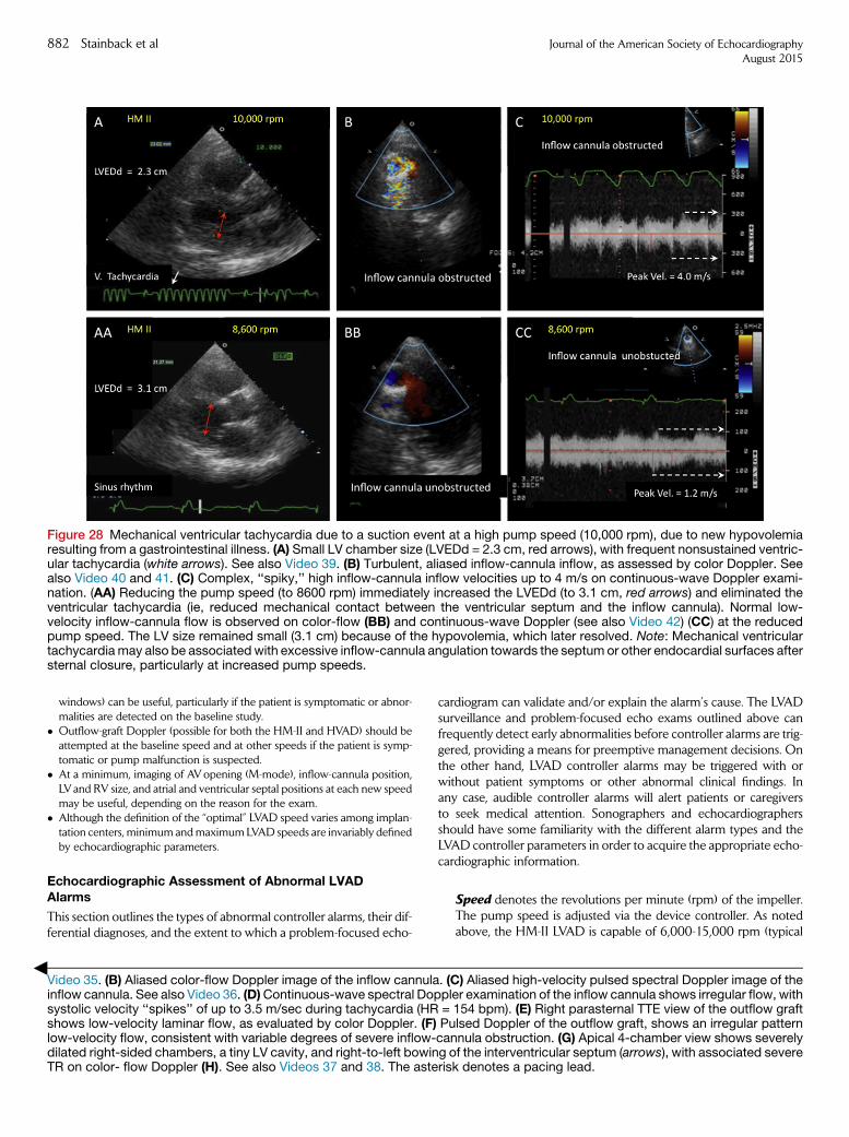
=
Figure 28 Mechanical ventricular tachycardia due to a suction event at a high pump speed (10,000 rpm), due to new hypovolemiaresulting from a gastrointestinal illness. (A) Small LV chamber size (LVEDd = 2.3 cm, red arrows), with frequent nonsustained ventric-ular tachycardia (white arrows). See also Video 39. (B) Turbulent, aliased inflow-cannula inflow, as assessed by color Doppler. Seealso Video 40 and 41. (C) Complex, ‘‘spiky,’’ high inflow-cannula inflow velocities up to 4 m/s on continuous-wave Doppler exami-nation. (AA) Reducing the pump speed (to 8600 rpm) immediately increased the LVEDd (to 3.1 cm, red arrows) and eliminated theventricular tachycardia (ie, reduced mechanical contact between the ventricular septum and the inflow cannula). Normal low-velocity inflow-cannula flow is observed on color-flow (BB) and continuous-wave Doppler (see also Video 42) (CC) at the reducedpump speed. The LV size remained small (3.1 cm) because of the hypovolemia, which later resolved. Note: Mechanical ventriculartachycardiamay also be associatedwith excessive inflow-cannula angulation towards the septum or other endocardial surfaces aftersternal closure, particularly at increased pump speeds.
882 Stainback et al Journal of the American Society of EchocardiographyAugust 2015
windows) can be useful, particularly if the patient is symptomatic or abnor-malities are detected on the baseline study.
� Outflow-graft Doppler (possible for both the HM-II and HVAD) should beattempted at the baseline speed and at other speeds if the patient is symp-tomatic or pump malfunction is suspected.
� At a minimum, imaging of AVopening (M-mode), inflow-cannula position,LVand RV size, and atrial and ventricular septal positions at each new speedmay be useful, depending on the reason for the exam.
� Although the definition of the ‘‘optimal’’ LVAD speed varies among implan-tation centers, minimum andmaximumLVAD speeds are invariably definedby echocardiographic parameters.
Echocardiographic Assessment of Abnormal LVADAlarms
This section outlines the types of abnormal controller alarms, their dif-ferential diagnoses, and the extent to which a problem-focused echo-
Video 35. (B) Aliased color-flow Doppler image of the inflow cannulainflow cannula. See also Video 36. (D)Continuous-wave spectral Dopsystolic velocity ‘‘spikes’’ of up to 3.5 m/sec during tachycardia (HRshows low-velocity laminar flow, as evaluated by color Doppler. (F)low-velocity flow, consistent with variable degrees of severe inflow-dilated right-sided chambers, a tiny LV cavity, and right-to-left bowinTR on color- flow Doppler (H). See also Videos 37 and 38. The aste
cardiogram can validate and/or explain the alarm’s cause. The LVADsurveillance and problem-focused echo exams outlined above canfrequently detect early abnormalities before controller alarms are trig-gered, providing a means for preemptive management decisions. Onthe other hand, LVAD controller alarms may be triggered with orwithout patient symptoms or other abnormal clinical findings. Inany case, audible controller alarms will alert patients or caregiversto seek medical attention. Sonographers and echocardiographersshould have some familiarity with the different alarm types and theLVAD controller parameters in order to acquire the appropriate echo-cardiographic information.
. (Cple=Pucang oris
Speed denotes the revolutions per minute (rpm) of the impeller.The pump speed is adjusted via the device controller. As notedabove, the HM-II LVAD is capable of 6,000-15,000 rpm (typical
) Aliased high-velocity pulsed spectral Doppler image of ther examination of the inflow cannula shows irregular flow, with154 bpm). (E) Right parasternal TTE view of the outflow graftlsed Doppler of the outflow graft, shows an irregular patternnula obstruction. (G) Apical 4-chamber view shows severelyf the interventricular septum (arrows), with associated severek denotes a pacing lead.

Table 4a LVAD Low-flow alarm differential and echocardiographic findings
VAD Alarm
Findings
HM-II *:
PI decrease
PI event
HVAD
Suction displayjj
HM-II*:
PI decrease
PI event
Low-flow alarm
Flow display ‘‘���’’
HVAD:
Low-flow display
Suction displayjj
HM-II*
PI decrease
PI event
Low-flow alarm
Flow display ‘‘���’’
HVAD:
Low-flow display
Suction displayjj
HM-II*
PI decrease
PI Event
Low-flow alarm
Flow display’’���’’
HVAD
Low-flow display
Suction displayjjHM-II*:
Increase PI#
HM-II*:
Decrease PI
PI event
Low-flow alarm
Flow display’’���;’’
HVAD:
Low-flow display
Suction displayjj
HM-II*:
Decrease PI
PI event
Low-flow alarm
Flow display ‘‘���’’
HVAD:
Low-flow display
Suction displayjjClinical
Diagnosis
LVAD suction event† Hypovolemia RV failure Tamponade Malignant hypertension Inflow thrombus or
outflow-graft
kinking/obstruction
Arrhythmias
Possible Echo
Findings‡
LV size: decrease LV size: decrease LV size: decrease LV size: decrease LV size: increase LV size: increase LV size: no changeRV size: depends
on cause
RV size: smaller or
no change
RV size: increase RV size: decrease RV size: no change RV size: no change RV size: may increase
Interatrial septal shift:
depends on cause†Interatrial septal
shift: no change
Interatrial septal shift:
towards left
Interatrial septal shift:
no change
Interatrial septal shift:
no change
Interatrial septal shift:
no change
Interatrial septal shift: may
shift left with RV failureInterventricular septal
shift: depends on
cause†
Interventricular septal
shift: no change
Interventricular septal
shift: towards left
Interventricular septal
shift: no change
Interventricular septal
shift: no change
Interventricular septal
shift: no change
Interventricular septal shift:
typically no change
AV opening: depends
on cause†
AV opening: may
decrease
AV opening: decrease AV opening: no change AV opening: decrease AV opening: increase AV opening: may decrease
MV regurgitation:
depends on cause†
MV regurgitation:
possible decrease
MV regurgitation: no
change
MV regurgitation: no
change
MV regurgitation:
increase
MV regurgitation:
increase
MV regurgitation: may
increaseTV regurgitation:
depends on cause†
TV regurgitation:
possible decrease
TV regurgitation:
increase
TV regurgitation:
may increase
TV regurgitation: no
change
TV regurgitation: no
change
TV regurgitation: may
increaseRAP estimate§:
depends on cause†
RAP estimate§:
decrease
RAP estimate§:
increase
RAP estimate§:
increase
RAP estimate§: no
change
RAP estimate§:
increase
RAP estimate§: may
increaseOther:
Inflow cannula
abutting endocardium
and position ‘‘off-axis’’#
Increased inflow-cannula
peak velocity with partial
obstruction as cause{Ventricular ectopy or
dysrhythmia on ECG
gating
Other: Other: Other:
Compressed left
and/or right atrium
Pericardial effusion
Other:
Increased outflow-
cannula peak systolic
velocity
Relative increase in
estimated left sided
ventricular filling and
pulmonary pressure
Other:
Elevated peak
outflow-cannula
velocity >2 m/s with
partial obstruction{Blunted change in
the following
parameters with
pump-speed
augmentation:
LVEDd reduction
RVOT VTI increase
MV DT increase
AV opening reduction
Other:
LVAD suction-event
findings may be seen
AV, aortic valve;DT,deceleration time;ECG, electrocardiography;HM-II, HeartMate II left ventricular assist device;HVAD,HeartWare ventricular assist device; LV, left ventricular; LVAD, left
ventricular assist device; LVEDd, left ventricular end-diastolic diameter;MR,mitral regurgitation;MV,mitral valve; PI, pulsatility index;RAP, right atrial pressure;RV, right ventricular; RVOT,
right ventricular outflow tract; TV, tricuspid valve; VAD, ventricular assist device; VTI, velocity time integral.*HeartMate (HM)-II feature. PI = Pulsatility index, which is the left ventricle’s pulsatile contribution to the pump; a PI event occurs when there is a 45% + or – change from the previous
15-second running average.†An LVAD suction event can be seen with hypovolemia, RV failure, and tamponade and may be associated with arrhythmias (atrial and/or ventricular) and/or inflow cannula malposition.‡Changes may be seen and are typically relative to individual benchmark data obtained from previous echo parameters at a similar LVAD pump speed.§Based on IVC size and response to inspiration and hepatic vein flow (diastolic predominance or systolic flow reversal).jjHVAD feature for suction event.{May observe diminished peak inflow and/or outflow velocity with complete obstruction (very rare).#Variable power/flow and PI changes can be seen, depending on the severity of hypertension.
Journalo
ftheAmerican
Society
ofEchocard
iograp
hy
Volume28Number
8Stain
back
etal
883
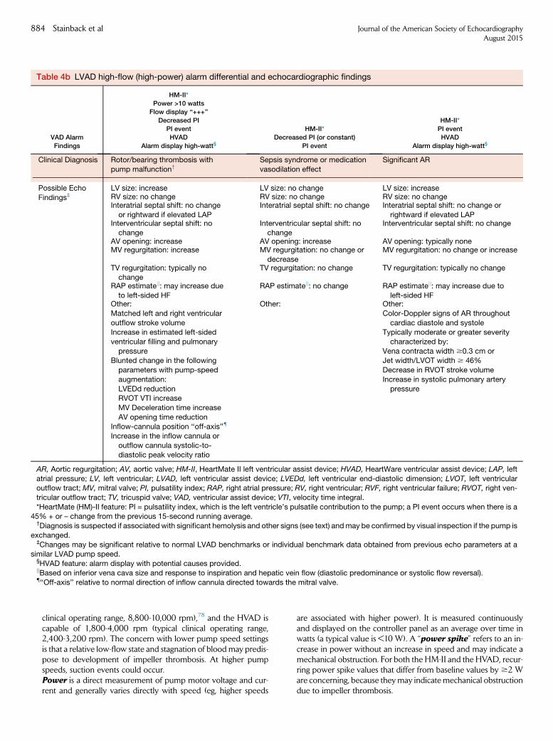
Table 4b LVAD high-flow (high-power) alarm differential and echocardiographic findings
VAD Alarm
Findings
HM-II*
Power >10 watts
Flow display ‘‘+++’’
Decreased PI
PI event
HVAD
Alarm display high-watt§
HM-II*
Decreased PI (or constant)
PI event
HM-II*
PI event
HVAD
Alarm display high-watt§
Clinical Diagnosis Rotor/bearing thrombosis with
pump malfunction†Sepsis syndrome or medication
vasodilation effect
Significant AR
Possible Echo
Findings‡LV size: increase LV size: no change LV size: increaseRV size: no change RV size: no change RV size: no changeInteratrial septal shift: no change
or rightward if elevated LAP
Interatrial septal shift: no change Interatrial septal shift: no change or
rightward if elevated LAPInterventricular septal shift: no
changeInterventricular septal shift: nochange
Interventricular septal shift: no change
AV opening: increase AV opening: increase AV opening: typically noneMV regurgitation: increase MV regurgitation: no change or
decrease
MV regurgitation: no change or increase
TV regurgitation: typically nochange
TV regurgitation: no change TV regurgitation: typically no change
RAP estimatejj: may increase due
to left-sided HF
RAP estimatejj: no change RAP estimatejj: may increase due to
left-sided HFOther:
Matched left and right ventricular
outflow stroke volumeIncrease in estimated left-sided
ventricular filling and pulmonary
pressureBlunted change in the following
parameters with pump-speed
augmentation:
LVEDd reductionRVOT VTI increase
MV Deceleration time increase
AV opening time reduction
Inflow-cannula position ‘‘off-axis’’{
Increase in the inflow cannula or
outflow cannula systolic-to-
diastolic peak velocity ratio
Other: Other:
Color-Doppler signs of AR throughout
cardiac diastole and systoleTypically moderate or greater severity
characterized by:
Vena contracta width $0.3 cm orJet width/LVOT width $ 46%
Decrease in RVOT stroke volume
Increase in systolic pulmonary artery
pressure
AR, Aortic regurgitation; AV, aortic valve; HM-II, HeartMate II left ventricular assist device; HVAD, HeartWare ventricular assist device; LAP, left
atrial pressure; LV, left ventricular; LVAD, left ventricular assist device; LVEDd, left ventricular end-diastolic dimension; LVOT, left ventricularoutflow tract; MV, mitral valve; PI, pulsatility index; RAP, right atrial pressure; RV, right ventricular; RVF, right ventricular failure; RVOT, right ven-
tricular outflow tract; TV, tricuspid valve; VAD, ventricular assist device; VTI, velocity time integral.
*HeartMate (HM)-II feature: PI = pulsatility index, which is the left ventricle’s pulsatile contribution to the pump; a PI event occurs when there is a45% + or – change from the previous 15-second running average.
†Diagnosis is suspected if associated with significant hemolysis and other signs (see text) andmay be confirmed by visual inspection if the pump is
exchanged.‡Changes may be significant relative to normal LVAD benchmarks or individual benchmark data obtained from previous echo parameters at a
similar LVAD pump speed.§HVAD feature: alarm display with potential causes provided.jjBased on inferior vena cava size and response to inspiration and hepatic vein flow (diastolic predominance or systolic flow reversal).{‘‘Off-axis’’ relative to normal direction of inflow cannula directed towards the mitral valve.
884 Stainback et al Journal of the American Society of EchocardiographyAugust 2015
clinical operating range, 8,800-10,000 rpm),78 and the HVAD iscapable of 1,800-4,000 rpm (typical clinical operating range,2,400-3,200 rpm). The concern with lower pump speed settingsis that a relative low-flow state and stagnation of bloodmay predis-pose to development of impeller thrombosis. At higher pumpspeeds, suction events could occur.Power is a direct measurement of pump motor voltage and cur-rent and generally varies directly with speed (eg, higher speeds
are associated with higher power). It is measured continuouslyand displayed on the controller panel as an average over time inwatts (a typical value is <10 W). A ‘‘power spike’’ refers to an in-crease in power without an increase in speed and may indicate amechanical obstruction. For both the HM-II and the HVAD, recur-ring power spike values that differ from baseline values by $2 Ware concerning, because theymay indicate mechanical obstructiondue to impeller thrombosis.

Journal of the American Society of EchocardiographyVolume 28 Number 8
Stainback et al 885
Flow (L/min) is an estimated value that is directly related to theselected speed (rotary pump rotation in rpm) and power. In esti-mating flow, the HVAD also accounts for blood viscosity derivedfrom the hematocrit. For the HVAD, a hematocrit change ofmore than 65% should prompt updating of the system monitorto avoid substantial flow calculation errors, especially at lowerLVAD speeds.9,81
Pulsatility denotes the difference between the minimum andmaximum flows calculated by the device and is analogous to thedifference between the trough and peak of an arterial waveformtracing. Pulsatility is directly related to residual native ventricularcontractility and is inversely related to afterload. The pulsatilityindex (PI) is a parameter relevant to the HM-II controller that istangentially related to pulsatility. The PI, also a derived value, is calcu-lated from the highest-to-lowest power readings over a range, dividedby the average power over that range. The PI corresponds to themagnitude of flow through thepumpandwill increasewith increasedpreload, improved ventricular contractility, and a reduced afterload.Alarms, in general, can be classified as either low-flow or high-flow/high-power. Pump parameter deviations and identifiedalarms should be placed in a clinical context (see Table 4) andvalidated with further testing when their etiology is not clearlyapparent to the MCS team. The clinical symptoms and signs,along with the type of LVAD alarm findings, will guide thediagnosis and treatment recommendations. Readers are referredto the most recent practice guidelines to review the clinicalpresentations and treatment recommendations for LVAD-specific problems (ie, pump thrombosis).4 The HM-II device’slow-flow alarms may be associated with, or defined by, one ormore of the following signs: the PI is decreased, a PI event is noted(a 45% +/– change from the previous 15-second running PIaverage), a low-flow alarm is displayed, or flow displayed as ‘‘—’’is noted as the flow estimate. HVAD low-flow alarms appear as‘‘Low Flow’’ or ‘‘Suction’’ on the controller alarm display.
KEY POINTS
� Key parameters common to most LVAD consoles are speed, power, andflow. LVAD controller alarms are typically triggered by abnormalities inone or more of these parameters.
� Knowledge of a patient’s clinical status, in addition to the alarm type, canhelp guide echocardiographers during image acquisition (to determine theextent of the exam) and interpretation.
� For clinical problem-solving, it may be useful to divide controller alarms intoeither ‘‘low-flow’’ or ‘‘high-flow,’’ as each of these is associated with a uniqueset of differential diagnoses (see Table 4a,b).
� ‘‘Low-flow’’ alarms can be caused by ‘‘suction events,’’ RV failure, hypovole-mia, cardiac tamponade, inflow-cannula/outflow-graft obstruction, malig-nant hypertension, and/or arrhythmias.
� ‘‘High-flow/high-power’’ alarms can be caused by pump thrombosis, sys-temic arterial vasodilation, significant AR, and/or recovery of native LV func-tion. Differentiation between possible causes of alarms generally requiresevaluation of both clinical and echocardiographic parameters.
Low-FlowAlarms. The differential diagnosis of low-flow alarms fo-cuses on patient-related factors, including LVAD suction events, RVfailure, hypovolemia, cardiac tamponade, apical inflow-cannula oroutflow-cannula kinking or obstruction, malignant hypertension,and atrial and ventricular arrhythmias.
Suction Events.–As previously noted, LVAD suction events relate tocontact of the inflow cannula and the LVendocardium, which results
in reduced inflow-cannula flow and can be associated with a changein clinical status (eg, presyncope and/or palpitations from ventriculararrhythmias) and/or LVAD function. Any condition that produces LVunder-filling places a patient at risk for LVAD suction events. Theseevents can result from hypovolemia (Figure 28), RV failure(Figure 27), cardiac tamponade (Figure 29), and/or pump speed set-tings that are too high for the prevailing hemodynamic conditions.During suction events, the LVAD ‘‘sucks down’’ the LV chamber toan abnormally small size, leading to a right-to-left ventricular septalshift. Patients with a malpositioned inflow cannula may be predis-posed to the development of intermittent inflow-cannula obstructionand/or ventricular arrhythmias from mechanical contact with adja-cent (usually septal) endocardium (Figure 28). Monitoring for possiblesuction events is an important component of a ramp or speed-changeprotocol, as discussed above. The treatment recommendation is typi-cally twofold: (1) decrease the pump speed and (2) identify and treatthe underlying cause of the event.
RVDysfunction.–There is a spectrum of RV dysfunction severity thatcan be defined clinically or by echocardiography. Right ventriculardysfunction may or may not be associated with suction events.With acceptable LVAD and RV function, the interventricular septumtypically is neutrally positioned at a pump speed that can provide anadequate cardiac output by virtue of an adequate available preloadfrom the right ventricle. In patients with advanced RV dysfunctionor failure (based on a severely elevated RV end-diastolic pressureand a very low RV cardiac output) investigation of a low-flow alarmmay reveal that the interventricular septum is significantly and contin-uously bowed towards the left ventricle. New or worsening RVdysfunction can be evaluated echocardiographically by assessingchanges from the baseline exam with regard to RV size and function,inferior vena cava size and collapsibility, Doppler measures of pulmo-nary pressures, and color and spectral Doppler interrogation of TRseverity (Figure 27).
Tamponade.–Clinically, pericardial or thoracic cavity tamponademay mimic RV failure and result in a low-flow alarm. Because theLVAD is generally the primary determinant of mitral inflow and signif-icantly influences outflow, there may not be an exaggerated flowparadox across any valves despite increased intrapericardial pressurein cases of tamponade. Therefore, clinical suspicion of tamponadeshould be high if pericardial effusion or a suspected hematoma is visu-alized (Figure 29) in conjunction with low-flow alarms and small LVand/or RV chambers. In any of these scenarios, the RVOT cardiacoutput will be decreased and will fail to vary as expected withpump speed changes.
Inflow-Cannula Obstruction.–Other causes of low-flow alarmsinclude partial or intermittent mechanical obstruction of the inflowcannula secondary to thrombosis, large vegetations, or endocardialcontact (eg, suction events). On echocardiography, findings will besimilar to those of primary pump dysfunction with regard to LVsize, septal shift, and AV opening. However, color and spectralDoppler-derived inflow-cannula velocities may be abnormallyincreased, frequently with non-uniform inflow velocity patterns(Figures 27 and 28), the severity of which may vary with thedegree of residual LVAD flow. The inflow-cannula spectral Dopplervelocities may be elevated as blood accelerates proximal to theobstruction, whereas outflow-graft velocities may be relativelydecreased and/or appear to have peak velocity variations. Two-dimensional and 3D TTE (and especially TEE) may show thrombiand vegetations obstructing cannulas or cardiac structures (eg, areas

Figure 29 Tamponade after LVAD implantation was suspected because of low LVAD flow unresponsive to speed changes. A large,loculated pericardial effusion is seen posterolateral and lateral to the left ventricle (arrows). (A) parasternal short-axis view. See alsoVideo 43. (B) The apical 4-chamber view ruled out signs of RV failure. See also Video 44. (C) Spectral Doppler examination of theinflow cannula ruled out inflow obstruction. (D) Pulsed Doppler evaluation of the RVOT shows very low VTIs (4-6 cm) at a highpump speed of 9000 rpm (HM-II). Although suggested in views C and D, respirophasic flow changes in flow velocities are frequentlyabsent in LVAD recipients.
886 Stainback et al Journal of the American Society of EchocardiographyAugust 2015
of hypertrabeculation being drawn into the inflow cannula).Inflow-cannula obstruction in the setting of a suction event is ‘‘dy-namic’’ and can be demonstrated on a ramp study by a small LV cavitysize and increased inflow-cannula velocities that normalize after re-ductions in pump speeds.
Mechanical Obstruction of the Outflow Graft.–Mechanicalobstruction of the outflow graft (eg, resulting from kinking, malposi-tion, external compression, or thrombosis) will function similarly toan increased afterload in opposing LVAD flow (Figures 23 and 30).Findings are similar to those of inflow-cannula obstruction, exceptthat Doppler interrogation of the outflow graft may reveal increasedor decreased velocities, depending upon the site and degree ofobstruction relative to the velocity sampling site. Inflow-cannulaDoppler interrogation may show normal or decreased velocities (de-pending upon the degree of the distal obstruction); the outflow-graftvelocities may be increased if sampled in the region of an obstructionbut may be normal or attenuated if sampled significantly proximal ordistal to the obstruction. A ramp study may be extremely helpful byrevealing attenuation of the expected intracardiac flow changes (eg,RVOT and LVOT VTIs, or conduit systolic-to-diastolic flow-velocity
ratios), LV chamber size, and the degree of AV opening at varyingpump speeds.
High-Flow/High-Power (or High-Watt) Alarms. The differen-tial diagnosis for high-power alarms focusing on patient characteristicsincludes impeller thrombosis, systemic arterial vasodilatation (sepsissyndrome versus a medication effect), or significant continuous AR.
Pump dysfunction can be caused by malfunction of a mechanicalcomponent, but it is more commonly caused by partial thrombosis ofthe impeller in CF-LVADs. Any condition that impedes the impellerrotation results in increased LVAD power consumption. In the settingof partial impeller thrombosis that results in high power consumption,the displayed high flow is a calculated and results in a false estimate ofhigh flow. Typically the actual flow is equivalent to baseline flow or isactually decreased. Clinical features associated with pump throm-bosis include hemolysis, which is characterized by hemoglobinuriaalong with elevated lactate dehydrogenase, total bilirubin, and serumfree hemoglobin levels.82,83 On echocardiography, primary pumpdysfunction secondary to thrombosis may manifest as signs ofreduced LV unloading in comparison with the previous surveillanceexam. Echocardiographic signs of reduced pump performance

Figure 30 Progressive outflow-graft anastomotic obstruction identified more than 1 year after initiation of LVAD support. Increasingpump speeds were necessary for adequate LVAD flow, which was paradoxically associated with an increased, instead of adecreased, LV diameter at higher pump speeds without evidence of systemic hypertension. Pump alarms had not yet been activated.TEE, upper esophageal ascending aorta short-axis view: (A) irregular contour of the distal outflow graft (‘‘kink’’ and oblique approach)with a small orifice size (arrows). See also Video 45. (B) Color-Doppler flow is turbulent/aliased (compared with the normal appear-ance [Figs. 6A, 13C, and 13D]). See also Video 46. (C)En face 3D view of the anastomosis (arrow) shows a small buttonhole orifice andsuggests neointimal hyperplasia (compare with the normal appearance [Fig. 6D]). (D) Continuous-wave Doppler image with a peaksystolic velocity of >3 m/s. Note that the outflow-graft anastomosis could not be visualized on TTE.
Journal of the American Society of EchocardiographyVolume 28 Number 8
Stainback et al 887
(reduced LV unloading) include an increased LVIDd, a septal shifttowards the right ventricle and (depending on residual ventricularfunction), increased AV opening in comparison with previousfindings, as defined in Table 4. In patients with serologic evidenceof possible intravascular hemolysis and/or proven internal pumpthrombosis, diastolic inflow-cannula and outflow-graft velocities, asmeasured by Doppler, are typically decreased in association withincreased inflow-cannula or outflow-graft peak systolic–to–diastolicflow-velocity ratios in comparison with those seen during the patient’sbaseline (surveillance) exam.80 Confirmatory evidence of coexistingpump dysfunction is provided by a subsequent speed-change or‘‘ramp-study’’ phase of the LVAD problem-focused exam.Obstruction resulting from any cause (eg, internal impeller throm-bosis, outflow-graft kinking, etc.) attenuates the expected changes in2D and inflow-cannula or outflow-graft velocity at varying pumpspeeds. For example, when the pump speed is increased, the ex-pected decrease in LVIDd, reduction in AV-opening frequency or
AV-opening duration, prolongation in MV deceleration time, and in-crease in RVOT stroke volume will not occur.77,79,80
Significant ARmayalso be associatedwith a high estimated LVADflow but with normal power.When added to normalmitral inflow, theaortic regurgitant volume can lead to an increased LV preload, whichmay result in increased native LVOT output and AV opening, withintermittent AR on color Doppler (Figures 9H,9J). Alternatively, theARmay be continuous if the contractile force is not sufficient to inter-rupt the regurgitant flow during systole (Figure 9C). With worseningAR, the LVIDd will progressively increase in comparison with thatobserved on previous surveillance exams, and there may be ventricu-lar septal bowing towards the right ventricle. Doppler flow across theinflow cannula and outflow graft will be normal or increased due tothe aorta–left ventricle–LVAD blind loop. However, the net forwardcardiac output downstream from the LVAD-to-aorta anastomosis, asreflected by the RVOT VTI-derived cardiac output, will bereduced,70,73 even though flow is markedly increased within the

Figure 31 The Berlin Heart EXCOR VAD has variable pump sizes ranging from 10 to 60 mL. Image reproduced with the permission ofBerlin Heart.
888 Stainback et al Journal of the American Society of EchocardiographyAugust 2015
LVAD circuit proximal to the outflow graft-to-aorta anastomosis(Figure 13). Mitral regurgitation may also increase due to increasedLV volume and filling pressure (Table 4).
Ventricular Recovery and/or Decreased LV Afterload. Thecombination of increased LVAD flow and increased power may alsobe due to ventricular recovery or an abnormally decreased LV afterload.Echocardiography can distinguish between these two conditions,particularly when the data are compared with previous surveillance findings.Increased LV filling (associated with LVrecovery) or a decreased after-load (associated with arteriolar vasodilatation resulting from sepsis orother causes and associated with decreased LV filling) will generallybe reflected by increased flow and increased power. Ventricular recoveryis characterized by serial improvements in LV systolic function (eg, anincreased LVEF and a reduced LV size, accompanied by an increasedAV-opening duration and improved RVOT and native LVOT cardiacoutputs) at baseline and lower pump speeds. Improvement in othermanifestations of HF, such as functional MR, pulmonary hyperten-sion, and TR, would be expected. Ventricular recovery can also beassociated with decreased LVAD flow due to the fact that a greaterportion of the cardiac output is being pumped through the AV bythe improved left ventricle. The LV chamber size and MR severitymay also decrease in the setting of abnormally reduced peripheralvascular resistance (decreased LV afterload) resulting from sepsis orother causes (eg, pharmacologic agents) without LV recovery. In thiscircumstance, Doppler interrogation of the LVAD inflow cannulaand outflow graft may show increased systolic velocities withapparent improvement in the LVEF. However, the ventricular septummay continuously bow into the left ventricle, whereas LV recovery isassociated with a normal ventricular septal orientation. The RVOTVTI-derived cardiac output will be increased in comparison to previ-ous surveillance-exam findings.
LVAD Recovery Echo Exam
A small percentage of patients recover sufficient native LV function toallow LVAD explantation. An LVAD recovery or ‘‘weaning’’ protocolcan play a pivotal role in the complex decision-making processregarding suitability for LVAD removal. The LVAD recovery echoexam is not frequently performed outside of MCS centers.However, it may be performed more often in the context of an orga-nized research protocol that may include site-specific variations. Aswith some other aspects of LVAD management, there are few out-
comes data and little consensus surrounding this potentially impor-tant phase of patient care. Although a detailed standard LVADrecovery echo protocol cannot be recommended at this time,Appendix H and the following discussion of basic concepts may beuseful for establishing a framework.
The LVAD recovery protocol can be considered when LVAD sur-veillance echocardiography suggests significant recovery of nativeLV function.70 The initial phase of the LVAD recovery protocol shouldbe the same as for any comprehensive LVAD echo exam performedat the baseline speed setting. Very low LVAD pump speeds are asso-ciated with retrograde device flow (Figure 26). After the echo exam atthe baseline pump setting, gradual speed reductions are used to iden-tify a pump speed at which there is no forward or reverse pump flow(net neutral flow). During most weaning protocols, spectral Dopplerinterrogation of the LVAD inflow cannula and of the outflow graft isused to determine the speed at which there is net neutral pump flow.Because of blood flow stasis within the entire LVAD system during thisphase of the exam, the LVAD recovery protocol typically includesconfirmation of adequate systemic anticoagulation before the examis started. To test the patient’s native LV functional reserve, an exercisetest (such as a 6-minute walking test or other cardiopulmonary test)should be considered at one or more time intervals at the net neutrallow pump speed.84,85 At the conclusion of the exercise test, LVfunction parameters, including the LVEF, should again be assessed.Early termination of the test with restoration of the baseline LVADspeed is warranted if the patient becomes symptomatic. SeeAppendix H for a sample protocol.
LVADs for Pediatric and Adolescent Patients
Pediatric and adolescent patients with advanced HF have fewer MCSoptions than adults and until recently were treated primarily withECMO. At this time, there are no approved intracorporeal VADs forsmall children. Two extracorporeal VADs, the Thoratec PediMagand the Berlin Heart EXCOR (see below), are FDA-approved for tem-porary and extended MCS, respectively. Currently, reports are verylimited concerning the use of echocardiography for evaluating pediat-ric VADs, partly because so few of these patients are encountered atany one center.86 It may be assumed that many of the same conceptsof LVAD echocardiographic imaging apply to pediatric and adult pa-tients. Furthermore, larger pediatric and adolescent patients may becandidates forMCS devices approved for use in adults. Specific details

Figure 32 Complementary X-ray CT (A, B) and echocardiogram (C, D) from a 25-year-old man with single ventricle physiology: L-transposition of the great arteries (L-TGA), complete atrioventricular septal defect (AV canal defect) and subpulmonic stenosis,and a nonfenestrated Fontan conduit (placed at age 5 years). Although he initially received an HM-II LVAD for destination therapy,he eventually underwent cardiac transplantation after 2 years of VAD support (BTT conversion). (A)Coronal-plane CT shows a normaloutflow graft, including the aortic anastomosis (arrow). (B) Near-sagittal-plane CT reveals an unobstructed inflow cannula. (C) Para-sternal long-axis view of a nonrestrictive VSD (blue color flow) and inflow cannula (arrow) within the morphologic RV. See also Video47. (D) Apical 4-chamber view showing the Fontan conduit (FC). See also Video 48.
Journal of the American Society of EchocardiographyVolume 28 Number 8
Stainback et al 889
concerning VAD suitability based on patient size are beyond the scopeof this document. It should be noted that there are no benchmarknormal LVAD inflow-cannula or outflow-graft flow velocities forsmaller patients. In addition, smaller LV chamber sizes may result inan increased propensity for inflow-cannula obstruction and, in somecases, the need for surgical modification of the MV apparatus.
Short-Term VAD Support for Pediatric Patients. A miniatur-ized version of the CentriMag VAD (see Figure A-6), the ThoratecPediMag extracorporeal centrifugal CF blood pump (previouslyknown as the Levitronix PediMag), is approved for short-term (acutebridge-to-recovery or bridge-to-decision) use as an LVAD, an RVAD,or a BiVAD in small children [FDA 510(k), October 2009]. Thepump is driven by a bearingless, magnetically levitated impeller andcan deliver flows of up to 1.5 L/min. Its echocardiographic features
are expected to be similar to those of the other CF-LVADs previouslydiscussed in this document.
Long-Term VAD Support for Pediatric Patients. The BerlinHeart EXCOR Pediatric VAD (Berlin Heart, Inc., TheWoodlands, TX) is currently the only VAD approved for BTT therapyin infants and small children. Since this device received FDA approvalin 2011, its use has grown significantly.87 The EXCOR is an extracor-poreal pneumatically driven pulsatile VAD that differs significantlyfrom similarly designed adult devices in that it offers a wide rangeof graduated cannula and pump chamber sizes (10 to 60 mL) toaccommodate the pediatric and adolescent population (Figure 31).In a prospective US multicenter cohort outcomes study of 204 pedi-atric patients, the 1-year survival rate was 75%: 64% of the patientsunderwent transplantation, 6% recovered and underwent device

890 Stainback et al Journal of the American Society of EchocardiographyAugust 2015
removal, and 5% continued to undergo device support at 1 year.87
These results represented a dramatic improvement over previouslyreported results of conventional management. The echocardio-graphic features of pulsatile pumps are characterized by inflow andoutflow that is not timed with the cardiac cycle (intermittent LV assis-tance). In ‘‘automatic mode’’ (maximum support) a sensor detects pas-sive chamber filling, which triggers ejection of blood. The device maybe set to lower ‘‘fixed-rate’’ settings for lower levels of support. For adiscussion of echocardiographic features that differ from those ofCF-LVADs, please refer to Estep and coauthors.49
KEY POINT
� In many respects, LVAD echocardiography in pediatric and adolescent pa-tients is similar to LVAD echocardiography in adults, but there are importantmethodological differences; and age-, size-, and device-specific benchmarkvalues have not yet been established.
Other Areas of Research
Current research in echocardiography includes the potential applica-tion of many parameters of myocardial function that have not beenincluded in the recommended protocols. Many of the traditional vari-ables used to assess systolic and diastolic function before MCS deviceimplantation are exquisitely preload and afterload dependent, andthe ability to extrapolate their usefulness in patients with continuousmechanical LV unloading is limited at this time. Of note, patients withrecurrent HF after LVAD implantation may have an increased preva-lence of a lower mitral deceleration index (deceleration time/mitral E)and of rightward interatrial-septal deviation suggestive of partial LVunloading. Recently a proposed diagnostic algorithm integrating sim-ple and standard echocardiographic parameters (ie, mitral E/A ratio,RA pressure, systolic pulmonary artery pressure, left atrial volume in-dex, and E/e0) reliably distinguished between invasively measurednormal and elevated LV filling pressures on baseline levels of LVADsupport as evidence of partial LV unloading.88 There are, however,no data to suggest that tailoring the pump speed setting to echo-derived diastolic parameters (eg, lowering the mitral inflow E velocityor prolonging the deceleration time by adjusting the pump speed) isassociated with symptomatic improvement.
Newer echocardiographically derivedmechanical metrics ofmyocar-dial function include myocardial displacement, velocity, deformation(strain), strain rate, twist, and dyssynchrony.19 Mechanical indices maybe assessed in longitudinal, circumferential, and radial vectors or as staticinformation using M-mode speckle tracking echocardiography (STE),spectral Doppler, integrated backscatter, or contrast agents. Increasinguse of MCS devices provides a fertile ground for further research totest the clinical utility of traditional and emerging functional metricsthat may be useful for predicting a patient’s clinical trajectory. Becausedata regarding the clinical use of advanced mechanical metrics arelimited or nonexistent at this time, we suggest that the recommendedbasic protocols provided for routine LVAD management be used as aframework to which more advanced data collection procedures canbe added in a methodical site-specific fashion.
KEY POINT
� Increasing clinical use of LVADs provides a fertile ground for testing the clin-ical utility of traditional and emerging functional metrics in predicting andmanaging a patient’s clinical trajectory.
Indications for Other Imaging Methods After LVADImplantation
One limitation of echocardiography is its inability to view the entireoutflow graft. On the other hand, CCT) allows direct, complete visual-ization of the LVAD, including the inflow-cannula position and theentire course of the outflow graft (Figure 32). This is a robust techniquefor assessing CF-LVAD complications such as RV compression second-ary to pericardial clot, cannula kinking and/or malposition, andthrombus.70,89,90 Using intraoperative findings as the gold standard,Raman and associates90 demonstrated that the sensitivity and speci-ficity of CCT in detecting cannula thrombosis or inflow-cannulamalpo-sition were 85% and 100%, respectively. A limitation of CCTrelates toradiation exposure and the risk of nephrotoxicity resulting from aniodinated contrast agent. However, for LVAD patients with a serumcreatinine level of <1.5 mg/dL and a glomerular filtration rate of >60mL/min/1.73m2,CCTappears to be safe.91 In thepresence of nondiag-nostic TTE and TEE, indications for CCT in a CF-LVAD patient include(1) clinical concern about inflow-cannula malposition (ie, unexplainedfrequent LVAD suction events, recurring ventricular dysrhythmias inde-pendent of LVAD console parameter deviations, or residual HF due topartial LV unloading), (2) suspected pump thrombosis (involving theinflow and/or outflow graft) with clinical evidence of hemolysis, (3) sus-pected LVAD malfunction due to outflow-graft kinking, and (4) exclu-sion of an intracardiac and/or aortic root clot in patients with anunexplained transient ischemic attack or stroke. Echocardiography re-mains the first-line test to screen for myocardial recovery; however, ifpoor acoustic windows preclude accurate assessment of ventricularsize and function, onemay use eithermultiple-gated acquisition equilib-rium radionuclide angiography or electrocardiographically gated CCTas a second-line alternative.4,70
KEY POINT
� Echocardiography may be inconclusive for LVAD complications, includinginflow-cannula malposition, pump thrombosis, outflow-graft kinking orobstruction, intra- or extracardiac thrombus, or cardiac compression (lowflow) secondary to a pericardial or extrapericardial thoracic hematoma oreffusion. In such cases, CCT can provide important complementary infor-mation for a more definitive diagnosis.
SUMMARY/DISCUSSION
Echocardiography is important in the management of LVAD patients.Guidance about when and how to perform echocardiography inthese patients has previously been lacking. Because the field ofMCS is relatively new, many of the recommendations made hereinare partly based on consensus expert opinion from several largeLVAD centers. In the literature, there is growing support for specificechocardiography parameters that may constitute contraindicationsor precautions before LVAD surgery. During and after LVAD implan-tation, one may use perioperative TEE and TTE/TEE, respectively,when needed, to confirm normal versus abnormal device functionand to determine whether or not the native heart is responding toLVAD support as expected. For organizing these recommendations,we have used a phase of care approach, which includes (1) preopera-tive assessment, (2) perioperative TEE, (3) postoperative surveillanceechocardiography, (4) postoperative problem-focused echocardiog-raphy, and (5) recovery protocols.

Journal of the American Society of EchocardiographyVolume 28 Number 8
Stainback et al 891
Patient Populations
Themajority of patients who receive LVADs are adults with end-stagedilated cardiomyopathies, and many of our recommendations applyto this group. The role of echocardiography in the management ofother, smaller populations is less established. These smaller (butpotentially growing) populations include patients with infiltrative car-diomyopathies, pediatric and adolescent patients with dilated cardio-myopathies, and pediatric or adult patients with complex congenitalheart disease (Figure 32). Because these smaller, less-studied groupsmay benefit from LVAD support, they are briefly discussed separatelywhen they are thought to overlap with adult dilated cardiomyopathypatients with regard to patient selection, device type, and functionalassessment after implantation. However, these special populationsmay require considerable individualized consideration with respectto patient and device selection and follow-up evaluation. Currently,published data about these populations are limited, and detailed rec-ommendations are not included in this document. A separate pediat-ric LVAD discussion is included towards the end of the document.
Frequency and Extent of Echocardiography
The number of LVAD patients living in the outpatient, ambulatoryenvironment has grown considerably over the past several years,and further growth is expected due to increasing patient survivaland expansion of implant centers. A primary goal of these recommen-dations is to provide a framework for managing a busy ambulatoryMCS center in an efficient manner. Figure 14 presents a reasonablestrategy for organizing routine surveillance echocardiography exami-nations for patients who are doing well after LVAD implantation.Routine surveillance echocardiography is useful for confirmingnormal LVAD function and assessing the native cardiac response toLVAD support over time. These exams are analogous to appropriateechocardiograms performed in HF patients without LVADs to eval-uate their response to guideline-basedmedical therapy.Many patientstolerate and even thrive on long-term LVAD support. However,routine follow-up surveillance echo exams are recommended toscreen for the development of known LVAD complications thatmay begin in an occult fashion (before symptoms or device alarms),including (but not limited to) de novo or worsening AR, inappropriatespeed settings due to either improvement or deterioration of nativeheart function, internal pump thrombosis, other conduit obstruction,aortic root thrombus, aortic cusp fusion, and ongoing/smoldering HFin inactive patients. Theoretically, early detection of LVAD complica-tions or early intervention in smoldering persistent HF shouldimprove patient outcomes and reduce hospital readmissions for overtHF or for problems that have activated device alarms. From an abun-dance of caution, some centers may perform too-frequent and/ortoo-detailed echocardiographic examinations. In such cases, theseguidelines may be useful for establishing the optimal frequency ofechocardiography examination, based on individual patient circum-stances. These recommendations also may help establish a reasonabletimetable for routine follow-up examination of patients who are do-ing well or who may be able to have an LVAD echo exam in a labo-ratory closer to their home. When a patient does develop overt signsor symptoms of HF or LVAD malfunction, the guidelines provide aframework for performing problem-focused echocardiography ex-aminations.
Laboratory Resources and Extent of Examination
A frequent concern is whether or not ‘‘speed changes’’ should be incor-porated into the LVAD echocardiography exam, as this could be anextremely labor- and time-intensive approach. Additionally, the distinct
echocardiography data elements obtained at each pump speed are notwell defined. In general, either a surveillance or a problem-focusedexam at the LVAD’s baseline pump speed should be equivalent to acomprehensive HF echocardiogram (not a limited study). AdditionalLVAD-specific imaging during the baseline exam simply includes(when possible) 2D and Doppler interrogation of the inflow cannula,outflow graft, and aortic anastomosis (using TEE if indicated).Thereafter, a ‘‘limited’’ exam at each pump speed is recommended.The extent of imaging required at each pump speed depends on thesuspected problem and should be targeted. In stable, asymptomatic pa-tients with normal LVAD function at baseline, subsequent pump speeddata acquisition can proceed quite expediently and may even beoptional for surveillance exams, depending on the center’s internalstandards. A framework for minimal speed-change parameters is pro-vided in the appendix section and can be adapted for each patient, de-pending on the situation at hand. Pump speed changes may beperformed periodically in asymptomatic patients, as this can be ameans of establishing a patient’s own benchmark data, which can beuseful for comparison if suspected abnormalities are apparent on sub-sequent exams. Speed-change/ramp studies can be useful, if not critical,for a problem-focused exam (eg, screening for pump malfunction inthe setting of hemolysis and suspected impeller thrombosis) and forthe assessment of LV recovery. Special knowledge of contraindicationsfor certain speed adjustments and of safety endpoints for speedchanges is required by personnel performing, supervising, and inter-preting the studies, and the necessary information is outlined in thetext and listed in the tables and appendices.
Patient flow within busy LVAD clinics may be streamlined byadvance scheduling of routine surveillance examinations so that theappropriate time, the necessary exam room space, and adequatelytrained sonographers are available, either within the facility’s dedi-cated echocardiography laboratory or within a dedicated satelliteechocardiography laboratory in the HF/MCS center. When abnor-malities are suspected, the type and extent of the examination canbe more readily determined if the knowledgeable sonographer andechocardiographer are provided with a detailed indication for exam-ination, as listed in the sample worksheet. In some cases, a limitedconfirmatory exam may be performed at the baseline pump speed,and a more detailed examination may be more appropriate after hos-pitalization. A new facet of examining LVAD patients is the need forarterial Doppler-derived BP measurement in many cases before start-ing the echocardiography exam and for ensuring safety and accurateinterpretation when higher pump speed changes are included in theexam. In general, a primary goal of this document is to provide aframework for incorporating echocardiography more efficiently intoboth the routine follow-up care and the acute care of LVAD patients.In the absence of validation and outcomes studies, considerable roomfor adaptation of these recommendations is possible according toinstitutional internal standards and individual patient circumstances.However, the provision of adequately trained personnel, appropriateequipment, and quality-improvement measures is necessary for theimplementation of echocardiography in these often complex cases,in which images are sometimes difficult to acquire and interpret.
Referring/Community Hospitals
Although LVAD expertise is required within device implantation andfollow-up facilities, an increasing number of ambulatory LVAD pa-tients can be expected to present at less experienced facilities becauseof either symptoms or device alarm reports. Therefore, an additionalgoal of this document is to provide an easily understood and available
SUPPLEMENTARY DATA
Supplementary data related to this article can be found at http://dx.doi.org/10.1016/j.echo.2015.05.008.
892 Stainback et al Journal of the American Society of EchocardiographyAugust 2015
key reference for non-expert echocardiographers. Ideally, suchindividuals will be able to quickly grasp key points, developproblem-solving skills, observe safety precautions, and effectivelycommunicate with referral centers when examining unexpectedLVAD patients. Potentially, local laboratories may develop the recom-mended level of sophistication for performing surveillance examina-tions that can be communicated to the tertiary implant center.
Other Devices
This document primarily addresses two FDA-approved, long-term,surgically implanted CF-LVADs (the HM-II and HVAD). However,echocardiographers may increasingly encounter temporary LVADs,which are briefly discussed in Appendix A in order to contextualizetheir use under the heading of MCS.
The Right Ventricle and Biventricular/RVAD Support
Right ventricular support is sometimes required, and outcomes maybe improved when RVAD support is provided at the time of initialLVAD implantation. Development of echocardiographic predictorsfor RV failure after LVAD implantation has been the focus of rela-tively intensive clinical investigation, as discussed in some detailwithin this document. Unfortunately, recommendations for a singleechocardiography parameter or set of parameters that can reliablypredict the need for biventricular support cannot be made at thistime. Instead, laboratories are encouraged to evaluate RV functionas extensively as they can and to use an aggregate assessment ofclinical and echocardiography parameters of RV dysfunction bothpre- and postoperatively for clinical decision-making. A detailed dis-cussion of the types of RVAD support that can be observed (whenneeded) and the use of echocardiography for assisting in the man-agement of biventricular support is beyond the scope of this docu-ment, although a brief discussion is included in Appendix A. Animportant role for echocardiography in patients with the clinicalappearance of RV failure after LVAD implantation (low LVADflow) is to exclude other causes, such as occult pericardial orthoracic tamponade.
In conclusion, the Writing Committee and its special contributorshope that this initial document will provide a framework for betterincorporating echocardiography into the care of LVAD patients.There are other MCS devices under development that may beincluded in future versions of this report. We hope that this documentwill also provide a stimulus for related validation and outcomesstudies in this emerging field.
NOTICE AND DISCLAIMER
This report is made available by the ASE as a courtesy referencesource for its members. It contains recommendations only and shouldnot be used as the sole basis for making medical practice decisions orfor taking disciplinary action against any employee. The statementsand recommendations contained in this report are based primarilyon the opinions of experts rather than on scientifically verified data.The ASE makes no express or implied warranties regarding thecompleteness or accuracy of the information in this report, includingthe warranty of merchantability or fitness for a particular purpose. Inno event shall the ASE be liable to you, your patients, or any otherthird parties for any decision made or action taken by you or suchother parties in reliance on this information. Nor does your use ofthis information constitute the offering of medical advice by the
ASE or create any physician-patient relationship between the ASEand your patients or anyone else.
ACKNOWLEDGEMENTS
The Writing Committee would like to thank Virginia Fairchild, of theTexas Heart Institute’s Department of Scientific Publications, for herexpert editorial assistance with the preparation of this manuscript.In addition, Dr. Stainback acknowledges Dr. O. H. Frazier for hismany years of LVAD clinical correlations.
REFERENCES
1. Frazier OH, Rose EA, Macmanus Q, Burton NA, Lefrak EA, Poirier VL,et al. Multicenter clinical evaluation of the HeartMate 1000 IP left ventric-ular assist device. Ann Thorac Surg 1992;53:1080-90.
2. Rose EA, Gelijns AC, Moskowitz AJ, Heitjan DF, Stevenson LW,Dembitsky W, et al. Long-term use of a left ventricular assist device forend-stage heart failure. N Engl J Med 2001;345:1435-43.
3. Stewart GC, Givertz MM. Mechanical circulatory support for advancedheart failure: patients and technology in evolution. Circulation 2012;125:1304-15.
4. FeldmanD, Pamboukian SV, Teuteberg JJ, Birks E, Lietz K, Moore SA, et al.The 2013 International Society for Heart and Lung Transplantation Guide-lines for mechanical circulatory support: executive summary. J Heart LungTranspl 2013;32:157-87.
5. Kirklin JK, Naftel DC, Pagani FD, Kormos RL, Stevenson LW, Blume ED,et al. Sixth INTERMACS annual report: a 10,000-patient database. J HeartLung Transplant 2014;33:555-64.
6. Moazami N, Fukamachi K, Kobayashi M, Smedira NG, Hoercher KJ,Massiello A, et al. Axial and centrifugal continuous-flow rotary pumps: atranslation from pump mechanics to clinical practice. J Heart Lung Trans-plant 2013;32:1-11.
7. Kar B, Basra SS, Shah NR, Loyalka P. Percutaneous circulatory support incardiogenic shock: interventional bridge to recovery. Circulation 2012;125:1809-17.
8. Pagani FD, Miller LW, Russell SD, Aaronson KD, John R, Boyle AJ, et al.Extended mechanical circulatory support with a continuous-flow rotaryleft ventricular assist device. J Am Coll Cardiol 2009;54:312-21.
9. Slaughter MS, Rogers JG, Milano CA, Russell SD, Conte JV, Feldman D,et al. Advanced heart failure treated with continuous-flow left ventricularassist device. N Engl J Med 2009;361:2241-51.
10. Aaronson KD, Slaughter MS, Miller LW, McGee EC, Cotts WG,Acker MA, et al. Use of an intrapericardial, continuous-flow, centrifugalpump in patients awaiting heart transplantation. Circulation 2012;125:3191-200.
11. IAC accreditation: getting started. 2014. http://www.intersocietal.org/iac/accreditation/gettingstarted.htm Accessed April 10, 2014.
12. Introduction/Steering Committee, Task Force 1: Training in AmbulatoryConsultative Longitudinal Cardiovascular Care, Task Force 2: Training inPreventive Cardiovascular Medicine, Task Force 3: Training in Electrocar-diography, Ambulatory Electrocardiography, Exercise Testing, Task Force4: Training in Multimodality Imaging, Task Force 5: Training in Echocardi-ography, et al. ACC 2015 Core Cardiovascular Training Statement(COCATS 4) (Revision of COCATS 3): A Report of the ACC Compe-tency Management Committee. J Am Coll Cardiol 2015;65:1721-3.
13. Gardin JM,AdamsDB,DouglasPS, FeigenbaumH,ForstDH,FraserAG, et al.Recommendations for a standardized report for adult transthoracic

Journal of the American Society of EchocardiographyVolume 28 Number 8
Stainback et al 893
echocardiography: a report from the American Society of Echocardiogra-phy’s Nomenclature and Standards Committee and Task Force for a Stan-dardizedEchocardiographyReport. JAmSocEchocardiogr2002;15:275-90.
14. Ventricular Assist Devices (VADs) as Destination Therapy (MM7220). Bal-timore, MD:Centers forMedicare &Medicaid Services. October 30, http://www.cms.gov/Outreach-and-Education/Medicare-Learning-Network-MLN/MLNMattersArticles/downloads/MM7220.pdf; 2010.
15. LevyWC,Mozaffarian D, Linker DT, Sutradhar SC, Anker SD, Cropp AB,et al. The Seattle Heart Failure Model: prediction of survival in heart fail-ure. Circulation 2006;113:1424-33.
16. Aaronson KD, Schwartz JS, Chen TM, Wong KL, Goin JE, Mancini DM.Development and prospective validation of a clinical index to predict sur-vival in ambulatory patients referred for cardiac transplant evaluation. Cir-culation 1997;95:2660-7.
17. Lang RM, Badano LP, Mor-Avi V, Afilalo J, Armstrong A, Ernande L, et al.Recommendations for cardiac chamber quantification by echocardiogra-phy in adults: an update from the american society of echocardiographyand the European association of cardiovascular imaging. J Am Soc Echocar-diogr 2015;28:1-39. e14.
18. Lang RM, Badano LP, Tsang W, Adams DH, Agricola E, Buck T, et al.EAE/ASE recommendations for image acquisition and display usingthree-dimensional echocardiography. J Am Soc Echocardiogr 2012;25:3-46.
19. Mor-Avi V, Lang RM, Badano LP, Belohlavek M, Cardim NM,Derumeaux G, et al. Current and evolving echocardiographic tech-niques for the quantitative evaluation of cardiac mechanics: ASE/EAE consensus statement on methodology and indications endorsedby the Japanese Society of Echocardiography. J Am Soc Echocardiogr2011;24:277-313.
20. Porter TR, Abdelmoneim S, Belcik JT, McCulloch ML, Mulvagh SL,Olson JJ, et al. Guidelines for the cardiac sonographer in the performanceof contrast echocardiography: a focused update from the American Soci-ety of Echocardiography. J Am Soc Echocardiogr 2014;27:797-810.
21. Topilsky Y, Oh JK, Shah DK, Boilson BA, Schirger JA, Kushwaha SS, et al.Echocardiographic predictors of adverse outcomes after continuous leftventricular assist device implantation. JACC Cardiovasc Imaging 2011;4:211-22.
22. Rudski LG, Lai WW, Afilalo J, Hua L, Handschumacher MD,Chandrasekaran K, et al. Guidelines for the echocardiographic assessmentof the right heart in adults: a report from the American Society of Echocar-diography endorsed by the European Association of Echocardiography, aregistered branch of the European Society of Cardiology, and the Cana-dian Society of Echocardiography. J Am Soc Echocardiogr 2010;23:685-713. quiz 86–8.
23. Fitzpatrick JR 3rd, Frederick JR, Hiesinger W, Hsu VM, McCormick RC,Kozin ED, et al. Early planned institution of biventricular mechanical cir-culatory support results in improved outcomes compared with delayedconversion of a left ventricular assist device to a biventricular assist device.J Thorac Cardiovasc Surg 2009;137:971-7.
24. Kirklin JK, Naftel DC, Kormos RL, Stevenson LW, Pagani FD, Miller MA,et al. Fifth INTERMACS annual report: risk factor analysis frommore than6,000 mechanical circulatory support patients. J Heart Lung Transplant2013;32:141-56.
25. Matthews JC, Koelling TM, Pagani FD, Aaronson KD. The right ventricularfailure risk score a pre-operative tool for assessing the risk of right ventric-ular failure in left ventricular assist device candidates. J Am Coll Cardiol2008;51:2163-72.
26. Kormos RL, Teuteberg JJ, Pagani FD, Russell SD, John R, Miller LW, et al.Right ventricular failure in patients with the HeartMate II continuous-flowleft ventricular assist device: incidence, risk factors, and effect on out-comes. J Thorac Cardiovasc Surg 2010;139:1316-24.
27. Grant AD, Smedira NG, Starling RC,Marwick TH. Independent and incre-mental role of quantitative right ventricular evaluation for the prediction ofright ventricular failure after left ventricular assist device implantation. JAm Coll Cardiol 2012;60:521-8.
28. Vivo RP, Cordero-Reyes AM, Qamar U, Garikipati S, Trevino AR,Aldeiri M, et al. Increased right-to-left ventricle diameter ratio is a strong
predictor of right ventricular failure after left ventricular assist device. JHeart Lung Transplant 2013;32:792-9.
29. Kato TS, Jiang J, Schulze PC, Jorde U, Uriel N, Kitada S, et al. Serial echo-cardiography using tissue Doppler and speckle tracking imaging tomonitor right ventricular failure before and after left ventricular assist de-vice surgery. JACC Heart Fail 2013;1:216-22.
30. Potapov EV, Stepanenko A, Dandel M, Kukucka M, Lehmkuhl HB,Weng Y, et al. Tricuspid incompetence and geometry of the right ventricleas predictors of right ventricular function after implantation of a left ven-tricular assist device. J Heart Lung Transplant 2008;27:1275-81.
31. Raina A, Seetha Rammohan HR, Gertz ZM, Rame JE, Woo YJ,Kirkpatrick JN. Postoperative right ventricular failure after left ventricularassist device placement is predicted by preoperative echocardiographicstructural, hemodynamic, and functional parameters. J Card Fail 2013;19:16-24.
32. Zoghbi WA, Enriquez-Sarano M, Foster E, Grayburn PA, Kraft CD,Levine RA, et al. Recommendations for evaluation of the severity of nativevalvular regurgitation with two-dimensional and Doppler echocardiogra-phy. J Am Soc Echocardiogr 2003;16:777-802.
33. Baumgartner H, Hung J, Bermejo J, Chambers JB, Evangelista A, Griffin BP,et al. Echocardiographic assessment of valve stenosis: EAE/ASE recom-mendations for clinical practice. J Am Soc Echocardiogr 2009;22:1-23.quiz 101-2.
34. Zoghbi WA, Chambers JB, Dumesnil JG, Foster E, Gottdiener JS,Grayburn PA, et al. Recommendations for evaluation of prosthetic valveswith echocardiography and doppler ultrasound: a report From the Amer-ican Society of Echocardiography’s Guidelines and Standards Committeeand the Task Force on Prosthetic Valves, developed in conjunction withthe American College of Cardiology Cardiovascular Imaging Committee,Cardiac Imaging Committee of the American Heart Association, the Eu-ropean Association of Echocardiography, a registered branch of the Euro-pean Society of Cardiology, the Japanese Society of Echocardiographyand the Canadian Society of Echocardiography, endorsed by the Amer-ican College of Cardiology Foundation, American Heart Association, Eu-ropean Association of Echocardiography, a registered branch of theEuropean Society of Cardiology, the Japanese Society of Echocardiogra-phy, and Canadian Society of Echocardiography. J Am Soc Echocardiogr2009;22:975-1014. quiz 82-4.
35. Park SJ, Liao KK, Segurola R, Madhu KP, Miller LW.Management of aorticinsufficiency in patients with left ventricular assist devices: a simple coap-tation stitch method (Park’s stitch). J Thorac Cardiovasc Surg 2004;127:264-6.
36. Shah NR, LamWW, Rodriguez FH 3rd, Ermis PR, Simpson L, Frazier OH,et al. Clinical outcomes after ventricular assist device implantation in adultswith complex congenital heart disease. J Heart Lung Transplant 2013.
37. Shapiro GC, Leibowitz DW, Oz MC, Weslow RG, Di Tullio MR,Homma S. Diagnosis of patent foramen ovale with transesophageal echo-cardiography in a patient supported with a left ventricular assist device. JHeart Lung Transplant 1995;14:594-7.
38. Kilger E, Strom C, Frey L, Felbinger TW, Pichler B, TichyM, et al. Intermit-tent atrial level right-to-left shunt with temporary hypoxemia in a patientduring support with a left ventricular assist device. Acta AnaesthesiolScand 2000;44:125-7.
39. Ammar KA, Umland MM, Kramer C, Sulemanjee N, Jan MF,Khandheria BK, et al. The ABCs of left ventricular assist device echocardi-ography: a systematic approach. Eur Heart J Cardiovasc Imaging 2012;13:885-99.
40. Hiratzka LF, Bakris GL, Beckman JA, Bersin RM, Carr VF, Casey DE Jr,et al. 2010 ACCF/AHA/AATS/ACR/ASA/SCA/SCAI/SIR/STS/SVMGuidelines for the diagnosis and management of patients with thoracicaortic disease. A Report of the American College of Cardiology Founda-tion/American Heart Association Task Force on Practice Guidelines,American Association for Thoracic Surgery, American College of Radi-ology, American Stroke Association, Society of Cardiovascular Anesthesi-ologists, Society for Cardiovascular Angiography and Interventions,Society of Interventional Radiology, Society of Thoracic Surgeons, and So-ciety for Vascular Medicine. J Am Coll Cardiol 2010;55:e27-129.

894 Stainback et al Journal of the American Society of EchocardiographyAugust 2015
41. American Society of Anesthesiologists and Society of Cardiovascular An-esthesiologists Task Force on Transesophageal Echocardiography. Practiceguidelines for perioperative transesophageal echocardiography. An up-dated report by the American Society of Anesthesiologists and the Societyof Cardiovascular Anesthesiologists Task Force on Transesophageal Echo-cardiography. Anesthesiology 2010;112:1084-96.
42. Hahn RT, Abraham T, Adams MS, Bruce CJ, Glas KE, Lang RM, et al.Guidelines for performing a comprehensive transesophageal echocardio-graphic examination: recommendations from the American Society ofEchocardiography and the Society of Cardiovascular Anesthesiologists. JAm Soc Echocardiogr 2013;26:921-64.
43. Ryan T, ArmstrongWF, Khandheria BK. American Society of E. Task force4: training in echocardiography endorsed by the American Society ofEchocardiography. J Am Coll Cardiol 2008;51:361-7.
44. Cahalan MK, Abel M, Goldman M, Pearlman A, Sears-Rogan P, Russell I,et al. American Society of Echocardiography and Society of Cardiovascu-lar Anesthesiologists task force guidelines for training in perioperativeechocardiography. Anesth Analg 2002;94:1384-8.
45. Cahalan MK, Stewart W, Pearlman A, Goldman M, Sears-Rogan P,Abel M, et al. American Society of Echocardiography and Societyof Cardiovascular Anesthesiologists task force guidelines for trainingin perioperative echocardiography. J Am Soc Echocardiogr 2002;15:647-52.
46. Greim CA, Trautner H, Kramer K, Zimmermann P, Apfel CC, Roewer N.The detection of interatrial flow patency in awake and anesthetized pa-tients: a comparative study using transnasal transesophageal echocardiog-raphy. Anesth Analg 2001;92:1111-6.
47. Gin KG, Huckell VF, Pollick C. Femoral vein delivery of contrast mediumenhances transthoracic echocardiographic detection of patent foramenovale. J Am Coll Cardiol 1993;22:1994-2000.
48. Woods TD, Patel A. A critical review of patent foramen ovale detectionusing saline contrast echocardiography: when bubbles lie. J Am Soc Echo-cardiogr 2006;19:215-22.
49. Estep JD, Stainback RF, Little SH, Torre G, Zoghbi WA. The role of echo-cardiography and other imaging modalities in patients with left ventricularassist devices. JACC Cardiovasc Imaging 2010;3:1049-64.
50. Shah NR, Cevik C, Hernandez A, Gregoric ID, Frazier OH, Stainback RF.Transthoracic echocardiography of the HeartWare left ventricular assistdevice. J Card Fail 2012;18:745-8.
51. Bennett MK, Roberts CA, Dordunoo D, Shah A, Russell SD. Ideal meth-odology to assess systemic blood pressure in patients with continuous-flow left ventricular assist devices. J Heart Lung Transplant 2010;29:593-4.
52. Lanier GM, Orlanes K, Hayashi Y, Murphy J, Flannery M, Te-Frey R, et al.Validity and reliability of a novel slow cuff-deflation system for noninva-sive blood pressure monitoring in patients with continuous-flow left ven-tricular assist device. Circ Heart Fail 2013;6:1005-12.
53. HeartWare Ventricular Assist System: Instructions for Use. Miami Lakes,FL: HeartWare, Inc., October 5, 2014, http://www.heartware.com/sites/default/files/uploads/docs/ifu00001_rev_15.pdf; 2012.
54. Markham DW, Drazner MH. Measuring nonpulsatile blood pressure: saygoodbye to the Doppler? Circ Heart Fail 2013;6:879-80.
55. Topilsky Y, Oh JK, Atchison FW, Shah DK, Bichara VM, Schirger JA, et al.Echocardiographic findings in stable outpatients with properly functioningHeartMate II left ventricular assist devices. J Am Soc Echocardiogr 2011;24:157-69.
56. LamKM, Ennis S, O’Driscoll G, Solis JM,Macgillivray T, PicardMH.Obser-vations from non-invasive measures of right heart hemodynamics in leftventricular assist device patients. J AmSocEchocardiogr 2009;22:1055-62.
57. Garcia-Alvarez A, Fernandez-Friera L, Lau JF, Sawit ST, Mirelis JG,Castillo JG, et al. Evaluation of right ventricular function and post-operative findings using cardiac computed tomography in patients withleft ventricular assist devices. J Heart Lung Transplant 2011;30:896-903.
58. Sauer AJ, Meehan K, Gordon R, Abicht T, Rich JD, Anderson AS, et al.Echocardiographic markers of left ventricular unloading using acentrifugal-flow rotary pump. J Heart Lung Transplant 2014;33:449-50.
59. Schiller NB, Shah PM, Crawford M, DeMaria A, Devereux R,Feigenbaum H, et al. Recommendations for quantitation of the left
ventricle by two-dimensional echocardiography. American Society ofEchocardiography Committee on Standards, Subcommittee on Quantita-tion of Two-Dimensional Echocardiograms. J Am Soc Echocardiogr 1989;2:358-67.
60. Quinones MA, Waggoner AD, Reduto LA, Nelson JG, Young JB,Winters WL Jr, et al. A new, simplified and accurate method for deter-mining ejection fraction with two-dimensional echocardiography. Circula-tion 1981;64:744-53.
61. Mancini DM, Beniaminovitz A, Levin H, Catanese K, Flannery M,DiTullio M, et al. Low incidence of myocardial recovery after left ventric-ular assist device implantation in patients with chronic heart failure. Circu-lation 1998;98:2383-9.
62. Nagueh SF, Appleton CP, Gillebert TC, Marino PN, Oh JK, Smiseth OA,et al. Recommendations for the evaluation of left ventricular diastolicfunction by echocardiography. J Am Soc Echocardiogr 2009;22:107-33.
63. Topilsky Y, Hasin T, Oh JK, Borgeson DD, Boilson BA, Schirger JA, et al.Echocardiographic variables after left ventricular assist device implantationassociatedwith adverse outcome.Circ Cardiovasc Imaging 2011;4:648-61.
64. Lee S, Kamdar F, Madlon-Kay R, Boyle A, Colvin-Adams M, Pritzker M,et al. Effects of the HeartMate II continuous-flow left ventricular assist de-vice on right ventricular function. J Heart Lung Transplant 2010;29:209-15.
65. Raina A, Vaidya A, Gertz ZM, Susan C, Forfia PR. Marked changes in rightventricular contractile pattern after cardiothoracic surgery: implicationsfor post-surgical assessment of right ventricular function. J Heart LungTransplant 2013;32:777-83.
66. Slaughter MS, Pagani FD, Rogers JG, Miller LW, Sun B, Russell SD, et al.Clinical management of continuous-flow left ventricular assist devices inadvanced heart failure. J Heart Lung Transplant 2010;29:S1-s39.
67. Mudd JO, Cuda JD, Halushka M, Soderlund KA, Conte JV, Russell SD.Fusion of aortic valve commissures in patients supported by a continuousaxial flow left ventricular assist device. J Heart Lung Transplant 2008;27:1269-74.
68. Cowger J, Pagani FD, Haft JW, RomanoMA, Aaronson KD, Kolias TJ. Thedevelopment of aortic insufficiency in left ventricular assist device-supported patients. Circ Heart Fail 2010;3:668-74.
69. Pak SW, Uriel N, Takayama H, Cappleman S, Song R, Colombo PC, et al.Prevalence of de novo aortic insufficiency during long-term support withleft ventricular assist devices. J Heart Lung Transplant 2010;29:1172-6.
70. Estep JD, Chang SM, Bhimaraj A, Torre-Amione G, Zoghbi WA,Nagueh SF. Imaging for ventricular function and myocardial recoveryon nonpulsatile ventricular assist devices. Circulation 2012;125:2265-77.
71. Hatano M, Kinugawa K, Shiga T, Kato N, Endo M, Hisagi M, et al. Lessfrequent opening of the aortic valve and a continuous flow pump arerisk factors for postoperative onset of aortic insufficiency in patients witha left ventricular assist device. Circ J 2011;75:1147-55.
72. Toda K, Fujita T, Domae K, Shimahara Y, Kobayashi J, Nakatani T. Lateaortic insufficiency related to poor prognosis during left ventricular assistdevice support. Ann Thorac Surg 2011;92:929-34.
73. Jorde UP, Uriel N, Nahumi N, Bejar D, Gonzalez-Costello J, Thomas SS,et al. Prevalence, significance, and management of aortic insufficiency incontinuous flow left ventricular assist device recipients. Circ Heart Fail2014;7:310-9.
74. Aggarwal A, Raghuvir R, Eryazici P, Macaluso G, Sharma P, Blair C, et al.The development of aortic insufficiency in continuous-flow left ventricularassist device-supported patients. Ann Thorac Surg 2013;95:493-8.
75. Horton SC, Khodaverdian R, Chatelain P, McIntosh ML, Horne BD,Muhlestein JB, et al. Left ventricular assist device malfunction: an approachto diagnosis by echocardiography. J Am Coll Cardiol 2005;45:1435-40.
76. Schwarz KQ, Parikh SS, Chen X, Farrar DJ, Steinmetz S, Ramamurthi S,et al. Non-invasive flow measurement of a rotary pump ventricular assistdevice using quantitative contrast echocardiography. J Am Soc Echocar-diogr 2010;23:324-9.
77. Uriel N, Morrison KA, Garan AR, Kato TS, Yuzefpolskaya M, Latif F, et al.Development of a novel echocardiography ramp test for speed optimiza-tion and diagnosis of device thrombosis in continuous-flow left ventricularassist devices: the Columbia ramp study. J Am Coll Cardiol 2012;60:1764-75.

Journal of the American Society of EchocardiographyVolume 28 Number 8
Stainback et al 895
78. HeartMate II LVAS: Clinical Operation & Patient Management. Pleasan-ton, CA: Thoratec Corporation. October 5, 2014, http://www.thoratec.com/_assets/download-tracker/HM_II_Clin_Op_&_Pt_Mgt_104185B_ENGLISH.pdf; 2011.
79. Estep JD, Vivo RP, Cordero-Reyes AM, Bhimaraj A, Trachtenberg BH,Torre-Amione G, et al. A simplified echocardiographic technique for de-tecting continuous-flow left ventricular assist device malfunction due topump thrombosis. J Heart Lung Transplant 2014;33:575-86.
80. Fine NM, Topilsky Y, Oh JK, Hasin T, Kushwaha SS, Daly RC, et al. Role ofechocardiography in patients with intravascular hemolysis due to sus-pected continuous-flow LVAD thrombosis. JACC Cardiovasc Imaging2013;6:1129-40.
81. Lund LH, Gabrielsen A, Tiren L, Hallberg A, El Karlsson K, Eriksson MJ.Derived and displayed power consumption, flow, and pulsatility over arange of HeartMate II left ventricular assist device settings. ASAIO J2012;58:183-90.
82. Cowger JA, RomanoMA, Shah P, Shah N, Mehta V, Haft JW, et al. Hemo-lysis: a harbinger of adverse outcome after left ventricular assist deviceimplant. J Heart Lung Transplant 2014;33:35-43.
83. Shah P, Mehta VM, Cowger JA, Aaronson KD, Pagani FD. Diagnosisof hemolysis and device thrombosis with lactate dehydrogenase duringleft ventricular assist device support. J Heart Lung Transplant 2014;33:102-4.
84. George RS, Sabharwal NK, Webb C, Yacoub MH, Bowles CT, Hedger M,et al. Echocardiographic assessment of flow across continuous-flow ven-tricular assist devices at low speeds. J Heart Lung Transplant 2010;29:1245-52.
85. George RS, Yacoub MH, Tasca G, Webb C, Bowles CT, Tansley P, et al.Hemodynamic and echocardiographic responses to acute interruptionof left ventricular assist device support: relevance to assessment ofmyocardial recovery. J Heart Lung Transplant 2007;26:967-73.
86. Sachdeva R, Frazier EA, Jaquiss RD, ImamuraM, Swearingen CJ, Vyas HV.Echocardiographic evaluation of ventricular assist devices in pediatric pa-tients. J Am Soc Echocardiogr 2013;26:41-9.
87. Almond CS, Morales DL, Blackstone EH, Turrentine MW, Imamura M,Massicotte MP, et al. Berlin Heart EXCOR pediatric ventricular assist de-vice for bridge to heart transplantation in US children. Circulation 2013;127:1702-11.
88. Estep JD, Vivo RP, Krim SR, Cordero-Reyes AM, Elias B, Loebe M, et al.Echocardiographic evaluation of hemodynamics in patients with systolicheart failure supported by a continuous-flow LVAD. J Am Coll Cardiol2014;64:1231-41.
89. Acharya D, Singh S, Tallaj JA, HolmanWL, George JF, Kirklin JK, et al. Useof gated cardiac computed tomography angiography in the assessment ofleft ventricular assist device dysfunction. ASAIO J 2011;57:32-7.
90. Raman SV, Sahu A, Merchant AZ, Louis LBt, Firstenberg MS, Sun B.Noninvasive assessment of left ventricular assist devices with cardiovascu-lar computed tomography and impact on management. J Heart LungTransplant 2010;29:79-85.
91. Chang SM, Kassi M, Sharifeh TMA, Wang H, Elias BA, Bhimaraj A, et al.Diagnostic utility and safety of contrast enhanced gated multislices cardiaccomputed tomography (CT) for evaluation of patients with left ventricularassist device (LVAD). Circulation 2012;126:A18981.
92. Levine GN, Bates ER, Blankenship JC, Bailey SR, Bittl JA, Cercek B, et al.2011 ACCF/AHA/SCAI Guideline for Percutaneous Coronary Interven-tion. A report of the American College of Cardiology Foundation/Amer-ican Heart Association Task Force on Practice Guidelines and the Societyfor Cardiovascular Angiography and Interventions. J Am Coll Cardiol2011;58:e44-122.
93. Impella 2.5 with the Impella Console: Instructions for Use & ClinicalReference Manual. Document No. 0046–9005, Rev D. Danvers, Massa-chusetts: ABIOMED, Inc.; 2011. March 17, 2014.

896 Stainback et al Journal of the American Society of EchocardiographyAugust 2015
APPENDIX A
Other FDA-Approved Pumps that may be Encountered bySonographers and Echocardiographers, IncludingPercutaneous, Extracorporeal, and Right Ventricular AssistDevicesPercutaneous LVADs for Temporary Support
A percutaneous LVAD (PVAD) can be expediently deployed in thecath lab with the aid of fluoroscopic guidance, either urgently to treatcardiogenic shock or preemptively to provide back-up support duringcertain high-risk percutaneous coronary interventions.92 Currently,two types of FDA-approved PVADs are available: the Impella System(Abiomed, Inc., Danvers, MA) and the TandemHeart System(CardiacAssist, Inc., Pittsburgh, PA).
Impella. The Impella 2.5 [FDA 510(k), 2008] and the slightly larger(up to 4 L/min) Impella CP (Cardiac Power) [FDA 510(k), 2012] areimplanted via a traditional femoral arterial approach. The largerImpella 5.0 [FDA 510(k), 2009] delivers flows of up to 5 L/minand requires surgical placement via a left axillary artery graft. Therole of echocardiography and the echocardiographic appearance isthe same for all three device sizes. The distal portion of the Impellasystem consists of a microaxial CF pump housed within a cannulathat draws blood into an LV inflow port and expels the blood throughan aortic root outlet port (intracardiac blood flow circuit) (Figure A1).
Echocardiography Before Deployment.–Significant AR is a relativecontraindication, and ventricular thrombus and severe AS or MS arecontraindications for use of the Impella. Echocardiography may beused to screen for these conditions and otherwise to confirm theextent and etiology of HF.
Echocardiography After Deployment.–Device console alarms orhemodynamic instability may prompt an urgent or ‘‘stat’’ echoexam to determine the source of the problem. Patient movement(eg, bed transfer, resuscitation, etc.) can cause catheter migration.The Impella is ideally imaged in its entirety in LVOT long-axis viewsby TTE or TEE. The visible inflow port should be positioned 3.5 to4.0 cm from the aortic annulus. The pump’s characteristic color-flow artifact should lie distal to the annulus. The cannula has a 45-degree angle to better track the normal LVOT course. However,this design can also predispose to entanglement of the distal pigtailportion of the device within the submitral apparatus (Figure A2).This complication may result in worse MR, inability to properlyadvance the device within the left ventricle and/or ‘‘low flow’’ alarmsif the adjacent MV leaflets obstruct the inflow zone. As with otherLVADs, the AV may be closed or only partially open after devicedeployment, and net forward flow can be determined by calculatingthe RVOT stroke volume and cardiac output with Doppler methods.Additional instructive information regarding echocardiography of theImpella systems is available online.93
TandemHeart. The TandemHeart PVAD [FDA 510(k), 2006] is in-serted via a femoral vein and requires an atrial transseptal puncture toaccess the left atrium. The extracorporeal centrifugal pump receivesleft atrial blood and delivers it to the femoral artery (via an extracar-diac blood flow circuit), providing up to 4 or 5 L/min of flow depend-ing on the size of the transseptal inflow cannula (Figure A3).
Echocardiography Before Deployment.–Left atrial thrombus is apotential contraindication for TandemHeart deployment. This devicemay be useful for cardiogenic shock—including severe postinfarction
VSD, severe MR, or severe AS—or in patients for whom the moreeasily deployed Impella device is contraindicated (eg, by severe ARor LV thrombus). Echocardiography may be used to screen for theseconditions and to otherwise confirm the severity and etiology of HFbefore device deployment.
Echocardiography After Deployment.–The only visible devicecomponent is the transseptal cannula, whichmay be seen throughoutits course from the left atrium, interatrial septum, right atrium, andinferior vena cava, using standard echo views. Color Doppler evalua-tion can confirm the presence of CF. In addition to verifying the can-nula position, the post-deployment echo exam is useful for assessingthe native heart’s response to circulatory support and the ability towithdraw temporary LVAD support. The net forward flow can becalculated from the RVOT stroke volume by Doppler methods. Thetransseptal cannula often enters the left atrial appendage. Becausethe cannula has 14 side holes, normal flow will occur even if the cath-eter tip abuts the wall of the left atrium or left atrial appendage(Figure A3C). Because the left ventricle may be completely bypassed,the sonographer should be alert for possible LV thrombus formation(Figure A4) and for aortic root thrombus when the AVremains closed.
Surgically Implanted Extracorporeal Ventricular AssistDevices for Temporary Support
Thoratec Paracorporeal Ventricular Assist Device
(VAD). The Thoratec Paracorporeal VAD (Thoratec Corporation,Pleasanton, CA) is a first-generation, pneumatically driven, pulsatiledisplacement pump with FDA 510(c) approval for BTT therapy(1995) and postcardiotomy recovery (1998). As shown inFigure A5, three potential VAD configurations may be used forLVAD or BiVAD support. The inflow cannula may be implantedwithin the left atrium, and this approach may useful for emergent sur-gical implantation by surgeons not experienced with the more chal-lenging procedure of off-pump LV cannulation. Although thedevice was also configured for intracorporeal support, this role hasbeen supplanted by the third-generation CF-LVADs. The echocardio-graphic features of pulsatile pumps are characterized by inflow andoutflow that is not timedwith the cardiac cycle (intermittent LVassist).In ‘‘automatic mode’’ (maximum support), a sensor detects passivechamber filling, which triggers ejection of blood. The device may beset to lower ‘‘fixed-rate’’ settings for lower levels of support. For a dis-cussion of echocardiographic features that differ from those of CF-LVADs, please refer to Estep and coauthors.49
Thoratec CentriMag (previously Levitronix CentriMag). TheCentriMag is approved for short-term LVAD, RVAD, or BiVAD sup-port. The extracorporeal centrifugal CF pump (Figure A6) is drivenby a bearingless, magnetically levitated impeller that can provideflows of up to 9.9 L/min. The inflow cannula and outflow graft areplaced surgically, usually via a midline sternotomy. The CentriMagis suitable for transporting patients between facilities. Difficultiesencountered by sonographers include possible suboptimal imagingwindows related to lack of sternal wiring (closure) and to patient intu-bation. When used for LVAD support, the inflow cannula may beplaced in either the right superior pulmonary vein (which may notbe visible on echo) or in the left ventricle (which is visible on echo).When the inflow cannula is placed in the right superior pulmonaryvein, the left ventricle may be completely ‘‘bypassed’’ if the AV doesnot open. As noted with the TandemHeart device (above), LV bloodstasis (Figure A4) increases the risk of LV thrombus formation, which
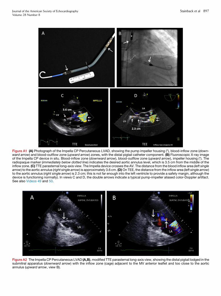
Figure A1 (A) Photograph of the Impella CP Percutaneous LVAD, showing the pump impeller housing (*), blood-inflow zone (down-ward arrow) and blood-outflow zone (upward arrow) zones, with the distal pigtail catheter component. (B) Fluoroscopic X-ray imageof the Impella CP device in situ. Blood-inflow zone (downward arrow), blood-outflow zone (upward arrow), impeller housing (*). Theradiopaque marker (immediately below dotted line) indicates the desired aortic annulus level, which is 3.5 cm from the middle of theinflow zone. (C) TTE parasternal long-axis view. The Impella device crosses the AV. The distance from the blood inflow area (left singlearrow) to the aortic annulus (right single arrow) is approximately 3.6 cm. (D)On TEE, the distance from the inflow area (left single arrow)to the aortic annulus (right single arrow) is 2.3 cm; this is not far enough into the left ventricle to provide a safety margin, although thedevice is functioning normally). In views C and D, the double arrows indicate a typical pump-impeller aliased color-Doppler artifact.See also Videos 49 and 50.
Figure A2 The Impella CPPercutaneous LVAD (A,B), modified TTE parasternal long-axis view, showing the distal pigtail lodged in thesubmitral apparatus (downward arrow) with the inflow zone (cage) adjacent to the MV anterior leaflet and too close to the aorticannulus (upward arrow, view B).
Journal of the American Society of EchocardiographyVolume 28 Number 8
Stainback et al 897

Figure A3 (A) Illustration of the TandemHeart PVAD (Images courtesy of CardiacAssist, Inc.). The CF pump is extracorporeal (outsidethe body). (B) TTE apical 4-chamber view shows the device’s inflow conduit within the left atrium. See also Video 51. (C) TEE showsthe distal cannula’s multiple-port inflow zone within the left atrial appendage (arrow). See also Video 52. (D) TEE shows the transatrialseptal portion of the inflow conduit (arrow). See also Video 53.
898 Stainback et al Journal of the American Society of EchocardiographyAugust 2015
can be identified echocardiographically. In other respects, the device’simaging characteristics are similar to those of long-term intracorporealdevices, as previously discussed in detail.
Right Ventricular Assist Devices
As previously noted, the primary population addressed in this guide-line consists of patients undergoing LVAD support alone. A briefdescription of RVADs is included, as echocardiographers mayencounter patients with RVAD (BiVAD) support. In the acute setting,including the period after LVAD implantation, an RVAD may beneeded. Right ventricular failure is difficult to manage long-term.The ability to predict the development of RV failure prospectively af-ter LVAD implantation is limited, and in some cases right-sided failure
can develop even if preimplantation RV function was seeminglyadequate. When optimization of LVAD function and medical man-agement have failed, the Impella, TandemHeart, HM-II, and HVADpumps have been used as RVADs (without FDA approval), and theThoratec PVAD, Berlin Heart EXCOR, CentriMag, and PediMaghave been used as RVADs with FDA approval. Other, less frequentlyused devices may also be available, and new systems are on the hori-zon. When an RVAD and LVAD are functioning simultaneously,many caveats are involved that are beyond the scope of this docu-ment. However, an important point is to observe both the RV andLV size, as both under-filling and over-pumping of either chambermay occur, potentially compromising device inflow or mechanicallydistorting the adjacent ventricle. Balance between the interventricularseptum and interatrial septum is important.

Figure A4 Severe left ventricle (LV) spontaneous echocardiog-raphy contrast in a patient with complete LV ‘‘bypass’’ (no aorticvalve opening) during TandemHeart support. The risk of LVthrombus is high without systemic anticoagulation therapy.Left Atrium (LA), Aortic Root (Ao), pericardial effusion (*), Tan-dem Heart inflow cannula (arrow). See also Video 54.
Journal of the American Society of EchocardiographyVolume 28 Number 8
Stainback et al 899

Figure A6 The Thoratec CentriMag extracorporeal centrifugalCF pump. The arrows indicate the blood-flow direction.
Figure A5 Drawing of the Thoratec Paracorporeal Ventricular Assist Device (VAD) and three cannulation approaches for univentric-ular left heart support (panelA) and biventricular support (panelsB andC). Ao=aorta, LA=left atrial appendage, PA=pulmonary artery,RA=right atrium, Apex=left ventricular apex, IAG=cannula inserted via the interatrial groove and directed towards the LA roof. Notethat VADs in PanelC are turned over and are on the sides of the chest that are opposite of those in Panel B. (Permission from Farrar DJet al. N Engl J Med 1988; 318:333-340).
900 Stainback et al Journal of the American Society of EchocardiographyAugust 2015
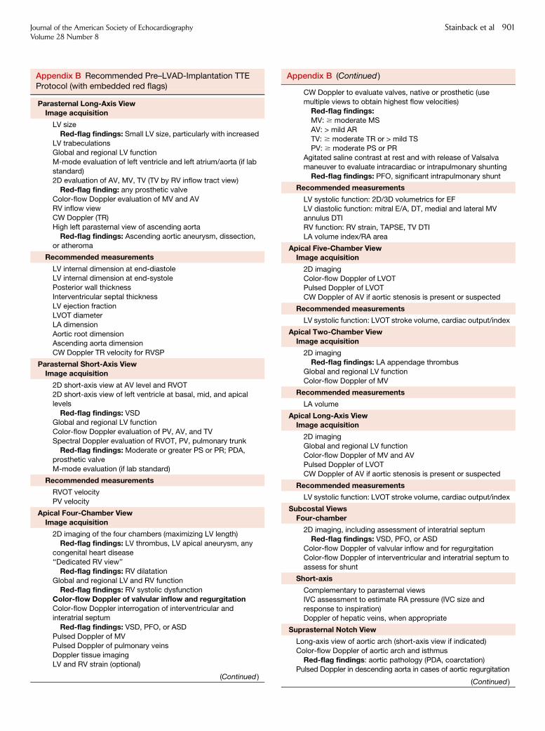
Appendix B Recommended Pre–LVAD-Implantation TTEProtocol (with embedded red flags)
Parasternal Long-Axis ViewImage acquisition
LV size
Red-flag findings: Small LV size, particularly with increased
LV trabeculationsGlobal and regional LV function
M-mode evaluation of left ventricle and left atrium/aorta (if lab
standard)2D evaluation of AV, MV, TV (TV by RV inflow tract view)
Red-flag finding: any prosthetic valve
Color-flow Doppler evaluation of MV and AV
RV inflow viewCW Doppler (TR)
High left parasternal view of ascending aorta
Red-flag findings: Ascending aortic aneurysm, dissection,
or atheroma
Recommended measurements
LV internal dimension at end-diastole
LV internal dimension at end-systolePosterior wall thickness
Interventricular septal thickness
LV ejection fraction
LVOT diameterLA dimension
Aortic root dimension
Ascending aorta dimensionCW Doppler TR velocity for RVSP
Parasternal Short-Axis ViewImage acquisition
2D short-axis view at AV level and RVOT2D short-axis view of left ventricle at basal, mid, and apical
levels
Red-flag findings: VSDGlobal and regional LV function
Color-flow Doppler evaluation of PV, AV, and TV
Spectral Doppler evaluation of RVOT, PV, pulmonary trunk
Red-flag findings: Moderate or greater PS or PR; PDA,prosthetic valve
M-mode evaluation (if lab standard)
Recommended measurements
RVOT velocity
PV velocity
Apical Four-Chamber ViewImage acquisition
2D imaging of the four chambers (maximizing LV length)
Red-flag findings: LV thrombus, LV apical aneurysm, any
congenital heart disease‘‘Dedicated RV view’’
Red-flag findings: RV dilatation
Global and regional LV and RV function
Red-flag findings: RV systolic dysfunctionColor-flow Doppler of valvular inflow and regurgitationColor-flow Doppler interrogation of interventricular and
interatrial septum
Red-flag findings: VSD, PFO, or ASDPulsed Doppler of MV
Pulsed Doppler of pulmonary veins
Doppler tissue imagingLV and RV strain (optional)
(Continued )
Appendix B (Continued )
CW Doppler to evaluate valves, native or prosthetic (use
multiple views to obtain highest flow velocities)Red-flag findings:MV: $ moderate MS
AV: > mild AR
TV: $ moderate TR or > mild TSPV: $ moderate PS or PR
Agitated saline contrast at rest and with release of Valsalva
maneuver to evaluate intracardiac or intrapulmonary shunting
Red-flag findings: PFO, significant intrapulmonary shunt
Recommended measurements
LV systolic function: 2D/3D volumetrics for EF
LV diastolic function: mitral E/A, DT, medial and lateral MVannulus DTI
RV function: RV strain, TAPSE, TV DTI
LA volume index/RA area
Apical Five-Chamber ViewImage acquisition
2D imaging
Color-flow Doppler of LVOTPulsed Doppler of LVOT
CW Doppler of AV if aortic stenosis is present or suspected
Recommended measurements
LV systolic function: LVOT stroke volume, cardiac output/index
Apical Two-Chamber ViewImage acquisition
2D imaging
Red-flag findings: LA appendage thrombus
Global and regional LV function
Color-flow Doppler of MV
Recommended measurements
LA volume
Apical Long-Axis ViewImage acquisition
2D imaging
Global and regional LV function
Color-flow Doppler of MV and AVPulsed Doppler of LVOT
CW Doppler of AV if aortic stenosis is present or suspected
Recommended measurements
LV systolic function: LVOT stroke volume, cardiac output/index
Subcostal ViewsFour-chamber
2D imaging, including assessment of interatrial septum
Red-flag findings: VSD, PFO, or ASD
Color-flow Doppler of valvular inflow and for regurgitation
Color-flow Doppler of interventricular and interatrial septum toassess for shunt
Short-axis
Complementary to parasternal viewsIVC assessment to estimate RA pressure (IVC size and
response to inspiration)
Doppler of hepatic veins, when appropriate
Suprasternal Notch View
Long-axis view of aortic arch (short-axis view if indicated)
Color-flow Doppler of aortic arch and isthmus
Red-flag findings: aortic pathology (PDA, coarctation)Pulsed Doppler in descending aorta in cases of aortic regurgitation
(Continued )
Journal of the American Society of EchocardiographyVolume 28 Number 8
Stainback et al 901

Appendix B (Continued )
CW Doppler of AV if aortic stenosis is present or suspected
SVC
Other ViewsRight parasternal window
Long-axis view to evaluate ascending aorta
CW Doppler of aortic valve if aortic stenosis is present orsuspected
Right supraclavicular window
SVCCW Doppler of aortic valve if aortic stenosis is present or
suspected
2D, two-dimensional; 3D, three-dimensional;A, mitral valve late peak
diastolic velocity; ASD, atrial septal defect; AV, aortic valve; CW,
continuous-wave; DT, deceleration time; DTI, Doppler tissue imag-
ing; E, mitral valve early peak diastolic velocity; EF, ejection fraction;IVC, inferior vena cava; LA, left atrial; LV, left ventricular; LVOT, left
ventricular outflow tract; MV, mitral valve; PDA, patent ductus arte-
riosus; PFO, patent foramen ovale; PR, pulmonary regurgitation;
PS, pulmonary stenosis; PV, pulmonary valve; RA, right atrial; RV,right ventricular; RVOT, right ventricular outflow tract; RVSP, right
ventricular systolic pressure; SVC, superior vena cava; TAPSE,
tricuspid annular-plane systolic excursion; TR, tricuspid regurgita-tion; TS, tricuspid stenosis; TTE, transthoracic echocardiography;
TV, tricuspid valve; VSD, ventricular septal defect.
902 Stainback et al Journal of the American Society of EchocardiographyAugust 2015

Appendix C Perioperative TEE Protocol/Checklist
Two-part exam. For standard views, see previous guidelines Hahn, et al.42
1. Preimplantation Perioperative TEE Exam
Goals: confirm previous echocardiography (TTE or TEE) findings; detect unexpected abnormal findings before and after LVAD implantationBlood pressure: via arterial line; for hypotension, consider vasopressor agent to assess AR severity
LV: size, systolic function, assess for thrombus
LA: size, assess for LA appendage/LA thrombus
RV: size, systolic function, catheters/leadsRA: size, assess for thrombus, catheters/leads
Interatrial septum: detailed 2D, color Doppler, IV saline contrast; red flag: PFO/ASD
Systemic veins: assess SVC, IVCPulmonary veinsAortic valve: red flags: > mild AR, prosthetic valve
Mitral valve: red flags: $ moderate mitral stenosis, prosthetic mitral valve
Pulmonary valve: red flags: > mild PS, $ moderate PR, if RVAD planned; prosthetic valvePulmonary trunk: red flags: congenital anomaly (PDA, pulmonary atresia or aneurysm)
Tricuspid valve: TR, systolic PA pressure by TR velocity; red flags: $ moderate TR, > mild TS, prosthetic valve
Pericardium: screen for effusion; consider constrictive physiology
Aorta: root, ascending, transverse, and descending thoracic aorta; screen for aneurysm, congenital anomaly, dissection, or complex atheroma ateach level
2. Postimplantation Perioperative TEE Exam
Goals: monitor for intracardiac air; rule out shunt; confirm device and native heart functionPump type:Pump speed:Blood pressure: via arterial line; for hypotension (MAP of <60 mmHg), consider vasopressor agent before assessing AR severity and other
hemodynamic variablesIntracardiac air: left-sided chambers and aortic root during removal from CPB
LV: size, inflow-cannula position and flow velocities, septal position; red flags: small LV (over-pumping or RV failure), right-to-left septal shift; large
LV (obstructed or inadequate pump flows)Inflow-cannula position: 2D/3D, assess for possible malposition
Inflow-cannula flow: spectral and color Doppler (red flag: abnormal flow pattern/high/low velocities, especially after sternal closure)
LA: Assess LA appendage
RV: size, systolic function; red flags: signs of RV dysfunctionRA: size, assess for thrombus, catheters/leads
Interatrial septum: repeat IV saline test and color Doppler evaluation of IAS (red flags: PFO/ASD)
Systemic veins: (SVC, IVC)Pulmonary veins: inspectAortic valve: degree of AV opening and degree of AR (red flags: > mild AR)
Mitral valve: exclude inflow-cannula interference with submitral apparatus; assess MR
Pulmonary valve: assess PR, measure RVOT SV if able
Pulmonary trunk: (if applicable, demonstrate RVAD outflow by color Doppler); assess PRTricuspid valve: assess TR (red flags: $ moderate TR); systolic PA pressure by TR velocity (if not severe TR)
Pericardium: screen for effusion/hematoma
Aorta: exclude iatrogenic dissectionOutflow graft: identify conduit path adjacent to RV/RA with color and spectral Doppler (when able)
Outflow graft-to-aorta anastomosis: assess patency/flow by color and spectral Doppler (when able) red flags: kinked appearance/turbulent
flow/velocity >2 m/sec, particularly after sternal closure
2D, Two-dimensional; 3D, three-dimensional; AR, aortic regurgitation; ASD, atrial septal defect; AV, aortic valve; CPB, cardiopulmonary bypass;
IAS, interatrial septum; IV, intravenous; IVC, inferior vena cava; LA, left atrium; LV, left ventricle; LVAD, left ventricular assist device; LVOT, left ven-
tricular outflow tract;MAP,mean arterial pressure;MR,mitral regurgitation; PA, pulmonary artery; PFO, patent foramen ovale; PDA, patent ductusarteriosus; PR, pulmonary regurgitation; PS, pulmonary stenosis, RA, right atrium; RV, ventricle; RVAD, right ventricular assist device; RVOT, right
ventricular outflow tract; SV, stroke volume; SVC, superior vena cava; TEE, transesophageal echocardiography; TR, tricuspid regurgitation; TS,
tricuspid stenosis; TTE, transthoracic echocardiography.
Journal of the American Society of EchocardiographyVolume 28 Number 8
Stainback et al 903

Appendix D Magnitude and Time Course of Echo LV Parameter Changes Induced by CF-LVAD Unloading
Variable
Pre-LVAD
Study 1 (N=21)
Study 2 (N=63)
Study 3 (N=80)
Post-LVAD 1 mo
Study 1 (N=21)
—
Study 3 (N=68)
Post-LVAD 3 mo
—
Study 2 (N=63)
Study 3 (N=47)
Post-LVAD 6 mo
Study 1 (N=10)
Study 2 (N=63)
Study 3 (N=32)
Post-LVAD 12 mo
—
—
Study 3 (N=20)
LV parametersLV diastolic diameter
Study 1 (mm)
Study 2 (mm)Study 3 (cm/m2)
66 6 11
68 6 93.2 (2.9, 3.6)
55 6 11**
—2.8 (2.3, 3.2)
—
56 6 11*2.9 (2.4, 3.4)
52 6 11*
57 6 122.8 (2.2, 3.4)
—
—2.6 (2.2, 3.0)*
LV systolic diameter
Study 1 (mm)
Study 2 (mm)Study 3 (cm/m2)
58 6 10
61 6 93.0 (2.6, 3.3)
47 6 12
—2.6 (2.0, 3.1)
—
47 6 13*2.6 (2.1, 3.1)
43 6 13
49 6 132.5 (1.8, 2.9)
—
—2.3 (1.9,2.8)*
LV end-diastolic volume
Study 1 (mL)
Study 2
Study 3 (mL/m2)
242 6 108
—
113 (94, 141)
127 6 68*
—
77 (54, 109)*
—
—
86 (62, 106)*
113 6 45*
—
86 (52, 108)*
—
—
69 (45, 93)*
LV end-systolic volume
Study 1 (mL)
Study 2
Study 3 (mL/m2)
191 6 93
—
3.0 (2.6, 3.3)
100 6 66*
—
2.6 (2.0, 3.1)*
—
—
2.6 (2.1, 3.1)
82 6 42*
—
2.5 (1.8,2.9)*
—
—
2.3 (1.9,2.8)*
LV ejection fraction (%)
Study 1Study 2
Study 3
22 6 519 6 7
17 (14, 23)
25 6 13—
20 (15, 30)
—26 6 12*
20 (14, 26)
29 6 1027 6 14
25 (18, 33)*
——
22 (15, 31)
LV mass
Study 1
Study 2(g)Study 3 (g/m2)
—
383 6 113114 (93, 146)
—
—95 (71, 114)**
—
295.9 6 188*92 (63, 118)**
—
314 6 134111 (74, 134)
—
—77 (50, 104)*
LV diastolic parametersLA size
Study 1 (mm)
Study 2 (mL/m2)
Study 3 (mL/m2)
47 6 7
69 6 30
46 (35, 54)
37 6 9**
—
28 (22, 36)*
—
42 6 15*
32 (23, 38)*
42 6 13
—
25 (19, 39)*
—
—
28 (18, 38)*
E-wave
Study 1 (cm/s)Study 2 (cm/s)
Study 3 (cm/s)
96 6 2398 6 35
100 (80, 110)
73 6 27**—
80 (60, 100)*
—100 6 160
80 (70, 100)
66 6 12**80 6 20
80 (70, 110)
——
100 (60, 120)
E/A ratio
Study 3 2.8 (2.1, 4.1) 2.2 (1.2, 3.6) 1.5 (1.0,2.9)* 1.6 (1.3, 2.2)** 1.7 (1.0, 3.3)
Mitral DT
Study 1Study 2
Study 3
124 6 39132 6 27
133 (112, 165)
180 6 53**—
175 (137, 220)*
—188 + 70*
178 (141, 212)*
164 6 24166 6 48
172 (121, 220)*
——
170 (157, 225)
Tissue Doppler e0 (cm/s)
Study 1Study 2 (septal e0)Study 3 (septal e0)
(lateral e0)
—4 6 1
4 (3, 6)
8 (5, 11)
——
6 (5, 9)*
9 (7, 10)
—4 6 1
7(5,9)*
9(6,11)
——
7 (4, 9)*
10 (7, 13)
——
7 (6, 10)**
12 (8, 12)
(Continued )
904 Stainback et al Journal of the American Society of EchocardiographyAugust 2015

Appendix D (Continued )
Variable
Pre-LVAD
Study 1 (N=21)
Study 2 (N=63)
Study 3 (N=80)
Post-LVAD 1 mo
Study 1 (N=21)
—
Study 3 (N=68)
Post-LVAD 3 mo
—
Study 2 (N=63)
Study 3 (N=47)
Post-LVAD 6 mo
Study 1 (N=10)
Study 2 (N=63)
Study 3 (N=32)
Post-LVAD 12 mo
—
—
Study 3 (N=20)
E/ e’ (ratio)
Study 1
Study 2 (septal e0)Study 3 (septal e0)
(lateral e0)
—
26 6 11
23 (16, 30)
14 (9, 19)
—
—
13 (9, 19)*
9 (16, 13)**
—
20 6 9**
12 (9, 16)*
10 (6, 12)
—
13 6 7
12 (9, 19)*
9 (7, 13)
—
—
15 (7, 17)**
10 (6, 11)
Study 1, Lam et al. JASE 200952; Study 2, Topilsky et al. JASE 201151; Study 3, Drakos et al. JACC 2013;61:1985-94. Values are mean 6 SD for
Studies 1 and 2 and median (25th, 75th percentiles) for Study 3; *P < .01 versus Pre-LVAD; **P < .05 versus Pre-LVAD. Study 2 P values only pro-vided comparing Pre-LVAD and Post-LVAD 3-momeasurements.A,mitral valve late peak diastolic velocity;CF, continuous-flow;DT, deceleration
time; E, mitral valve early peak diastolic velocity; e0, mitral annular velocity; LA, left atrial; LV, left ventricle; LVAD, left ventricular assist device.
Journal of the American Society of EchocardiographyVolume 28 Number 8
Stainback et al 905

Appendix E LVAD Surveillance Echo Protocol: StandardComprehensive TTE (or TEE) with Additional LVAD-SpecificParameters
Blood pressure (if no pulse, Doppler-derived mean arterialpressure)
Pump type and baseline speed
Degree of aortic valve opening/closureVentricular and interatrial septal positionLV inflow cannula
� Location
� Note optimal view for visualization� Flow type
� Flow direction
� Peak systolic and diastolic flow velocities (pulsed Doppler)
� Velocity flow pattern
LV outflow graft
� Location/Note optimal view for visualization
� Flow type� Flow direction
� Peak systolic and diastolic flow velocities (pulsed Doppler)
� Velocity flow pattern
LVAD output
� Outflow-graft pulsed Doppler VTI
� Cross-sectional area as calculated from the measured cannula
diameter or from the known cannula diameter
Total cardiac output
� RVOT pulsed Doppler VTI
� Calculated cross-sectional area from the RVOT diameter
Pericardium: effusion/hematomaPost-VAD Placement ‘‘Red Flag’’ Echo Findings
� Ventricular and/or atrial septal shift from mid-line
� Intracardiac shunt� Excessive increase in cannula velocities
� Mechanical cannula obstruction
� Cannula suction event� Worsening aortic or mitral regurgitation
� Cardiac thrombus
� Pericardial hematoma/effusion, with or without tamponade
� RV dysfunction (multiple parameters in aggregate)B Enlarged RV cavity size
B RV systolic dysfunction (quantitative, if possible)
B Moderate or severe TR
B Elevated RA pressure
LV, Left ventricular; LVAD, left ventricular assist device; RA, rightatrial; RV, right ventricular; RVOT, right ventricular outflow tract;
TEE, transesophageal echocardiography; TR, tricuspid regurgita-
tion; TTE, transthoracic echocardiography; VTI, velocity-time inte-
gral.Refer toTable 2 for guidance regarding the possible implications of
abnormal / ‘‘red-flag’’ findings.
906 Stainback et al Journal of the American Society of EchocardiographyAugust 2015

Appendix F LVAD Optimization/Ramp Echo Protocol
Perform baseline LVAD surveillance study (annotate BP, pump type, baseline pump speed)At baseline pump speed, acquire the following:
� LVIDd in the parasternal long-axis view� RV VTI (to calculate cardiac output) in the parasternal short-axis view
� AV opening by 2D and M-mode in the parasternal long-axis view (color Doppler M-mode if needed)
� 2D imaging in the parasternal long- and short-axis views
� Color Doppler examination of AR and MR in the parasternal long-axis and apical views� Color Doppler examination of TR in the RV inflow and apical four-chamber view
� Standard mitral valve PW Doppler inflow parameters
� Positioning of the interventricular and interatrial septa
Decrease pump speed to as low as 8000 rpm (for HM-II)
or
Decrease pump speed to as low as 2400 rpm (for HVAD)
� Wait 2 minutes
� Repeat data acquisition
Increase pump speed by 400 rpm (for HM-II)
or
Increase pump speed by 20-40 rpm (for HVAD)
� Wait 2 minutes� Repeat data acquisition
HM-II:
Continue to increase pump speed in 400-rpm increments to a pump speed of up to 12,000 rpm or until endpoint (below), acquiring data at
each stage
HVAD:
Continue to increase pump speed in 20-40 rpm increments to a pump speed of up to 3,200 rpm, or until endpoint (below), acquiring data at
each stage
Endpoints
� Completion of test
� Suction event: decrease in LV size (typically <3 cm), +/- ventricular ectopy, +/- inflow- cannula intermittent obstruction, leftward ventricularseptal shift, worsening TR
� Symptoms including, but not limited to, palpitations, dizziness, chest pain, shortness of breath, or headache
� Hypertension (eg, MAP > 100 mm Hg or symptoms)
� Hypotension (eg, MAP < 60 mm Hg or symptoms)
2D, Two-dimensional; AR, aortic regurgitation; AV, aortic valve; BP, blood pressure; HM-II, HeartMate II; HVAD, HeartWare ventricular assist sys-tem; LV, left ventricular; LVAD, left ventricular assist device; LVIDd, left ventricular internal diameter at end-diastole;MAP,mean arterial pressure;
MR,mitral regurgitation;PLAX, parasternal long-axis;PW, pulsedDoppler;RV, right ventricular; TR, tricuspid regurgitation; TV, tricuspid valve; VTI,
velocity-time integral.
Note: Inflow-cannula color and spectral Doppler (including CWDoppler) should be evaluated at each pump speed to test for obstruction. Outflow-graft Doppler evaluation is needed at baseline but is optional at speed changes if LVAD function is normal. When abnormal conditions are being
evaluated, additional parameters may be assessed when possible, such as outflow-graft velocity profile/stroke volume (eg, for obstruction or to
assess AR volume) and outflow-graft–to–aortic anastomosis to assess obstruction or flow reversal.
Journal of the American Society of EchocardiographyVolume 28 Number 8
Stainback et al 907

Appendix G Speed Changes: LVAD Optimization or Problem-Focused (Ramp) Protocol Worksheet
Speed Changes: LVAD Optimization or Problem-Focused (Ramp) Protocol Worksheet
CF-LVAD type: Implant date: [PT INR = _____ PTT = _____]
Previous echo exam date and significant
findings:
� Optimization protocol. Optimal speed based on MCS center’s own standard; sample order sets include the following: (a) Attain at least
intermittent AV opening, or (b) attain neutral IVS position and/or mild or less MR, or (c) attain complete AV closure to maximize LV
unloading or (d) adjust speed to below the maximum speed associated with complete AV closure and the minimum speed associated with
more prominent MR and rightward IVS.� Problem-focused protocol. Indication for exam: Sample order sets include the following indications:
a. Smoldering left- and/or right-sided heart failure.
b. Screen for pump function in setting of hemolysis and suspected pump thrombosis.c. Other LVAD-alarm trouble-shooting.
Pump Speed (rpm) BP AV Opening(y/n/intermittent)
LVIDd(cm)
RVOTVTI (cm)
SignifAR (y/n)
SignifMR (y/n)
SignifTR (y/n)
TR Velocity(m/s)
MV Peak EVelocity
(m/sec),
DT (ms)
IVS DirectionL/R/Neutral
a. Symptoms (y/n)b. Evidence of Inflow-
Cannula Obstruction
(y/n)
Reason for termination: (eg, signs of inflow-cannula obstruction, hypotension, hypertension, worsening RV or LV function, etc.)Final speed setting = ____ rpmFinal BP = ______ mmHg
AR, Aortic regurgitation; AV, aortic valve; BP, blood pressure;CF, continuous-flow;DT, deceleration time; E, early diastole; INR, international normalized ratio; IVS, interventricular septum;LV, left ventricular; LVAD, left ventricular assist device; LVIDd, left ventricular internal diameter at end-diastole; MCS, mechanical circulatory support; MR, mitral regurgitation; MV, mitral
valve; PT, prothrombin time; PTT, partial thromboplastin time; RVOT, right ventricular outflow tract; TR, tricuspid regurgitation; VTI, velocity-time integral.
Note: Parameters measured at each speed setting may vary according to an implant center’s internal standards. After examination at the baseline pump speed, most of the needed pa-
rameters at subsequent pump speeds may be obtained primarily from parasternal views in most cases, as a limited exam.
908
Stainback
etal
Journalo
ftheAmerican
Society
ofEchocard
iograp
hy
August2015

Appendix H LVAD Recovery Protocol Worksheet
LVAD Recovery Protocol Worksheet
CF-LVAD type: Implant date:
Previous echo exam date and significant findings:
PT INR = _____(ensure $2.0); PTT = _____(heparin to be used if INR is <2.0 per institutional protocol)
Baseline speed setting = _____rpm;
Low speed testing target achieved:
6000 rpm (HM-II) by increments of 1000 rpm from baseline
1800 rpm (HVAD) by increments of 100 rpm from baseline
Echocardiographic Measurements
Pump Speed
(rpm)
BP Direction of Inflow-
Cannula/Outflow-
Graft Flow: Forward
(f) Neutral (n)
Reverse (r)
AV Opening
(y/n/intermittent)
vs miliseconds
(M-mode)
LVEF LVIDd
(cm)
RV systolic
function
normal?
(y/n)
RV size
normal
(y/n)
RVOT
VTI (cm)
Signif AR
(y/n)
Signif MR
(y/n)
Signif
TR (y/n)/TR
Velocity (m/s)
MV Peak E
Velocity (m/s),
DT (ms)
Exercise Test
(y/n)
Symptoms
(y/n)
Baseline pump speed
Low pump speed
At intervals per institutional standards
The above echo measurements will be obtained
at baseline and low pump speed at different time intervals:i. After 5 min of low speedii. After 15 min of low speediii. After 6-min walk*
Hemodynamic measurements
(rest 6 exercise) per institutional standards
eg, systolic BP, diastolic BP, mean BP, HR,
and Swan-Ganz catheter measurements at the following intervals:i. Baseline rpmii. 0 min of low speediii. 5 min of low speediv. 10 min of low speedv. 15 min of low speedvi. After 6-min walk at low speed
Reason for termination (circle) Shortness of breath, chest pain,
blurred vision, dizziness, abdominal pain
(perform 12-lead ECG if chest pain is noted)
Final speed setting = ____ rpm
Final BP = _____ mmHg
Final clinical status:
AR, Aortic regurgitation; AV, aortic valve; BP, blood pressure; CF, continuous-flow; DT, deceleration time; E, early diastole; ECG, electrocardiography; HM-II, HeartMate left ventricularassist device; HR, heart rate; HVAD, HeartWare ventricular assist system; INR, international normalized ratio; IVS, interventricular septum; LV, left ventricular; LVAD, left ventricular assist
device; LVEF, left ventricular ejection fraction; LVIDd, left ventricular internal diameter at end-diastole;MCS,mechanical circulatory support;MR,mitral regurgitation;MS,mitral stenosis;
MV, mitral valve; PT, prothrombin time; PTT, partial thromboplastin time; RVOT, right ventricular outflow tract; TR, tricuspid regurgitation; VTI, velocity-time integral.
Note: Parameters measured at each speed setting and the type and timing of physiologic/exercise testing performed may vary according to an implant center’s internal standards. Afterexamination at the baseline pump speed, most of the needed parameters at subsequent pump speedsmay be obtained primarily from parasternal views in most cases, as a limited exam. If
a quantitative LVEF (preferred) is not obtainable, a qualitative LVEF should be provided.
*Institutional standards regarding spare batteries, second controller availability, and alarm-off mode settings should be followed and confirmed with the LVAD team.
Journalo
ftheAmerican
Society
ofEchocard
iograp
hy
Volume28Number
8Stain
back
etal
909