Ecg
7
“Designing & Implementation of Digital Filter for removal of Power Supply Noise” A SEMINAR REPORT Submitted by NAIVEDYA MISHRA(2011H140033H) M ASHWIN(2011H140038H) PEEYUSH PASHINE(2011H140033H) PRAVESH TAMRAKAR(2011H140036H) M.E. (EMBEDDED SYSTEMS) BIRLA INSTITUTE OF TECHNOLOGY AND SCINCE PILANI- HYDERABAD
-
Upload
peeyush-pashine -
Category
Documents
-
view
1.192 -
download
2
Transcript of Ecg
“Designing & Implementation of Digital Filter for removal
of Power Supply Noise”
A SEMINAR REPORT
Submitted by
NAIVEDYA MISHRA(2011H140033H)
M ASHWIN(2011H140038H)
PEEYUSH PASHINE(2011H140033H)
PRAVESH TAMRAKAR(2011H140036H)
M.E. (EMBEDDED SYSTEMS)
BIRLA INSTITUTE OF TECHNOLOGY AND SCINCE PILANI-
HYDERABAD
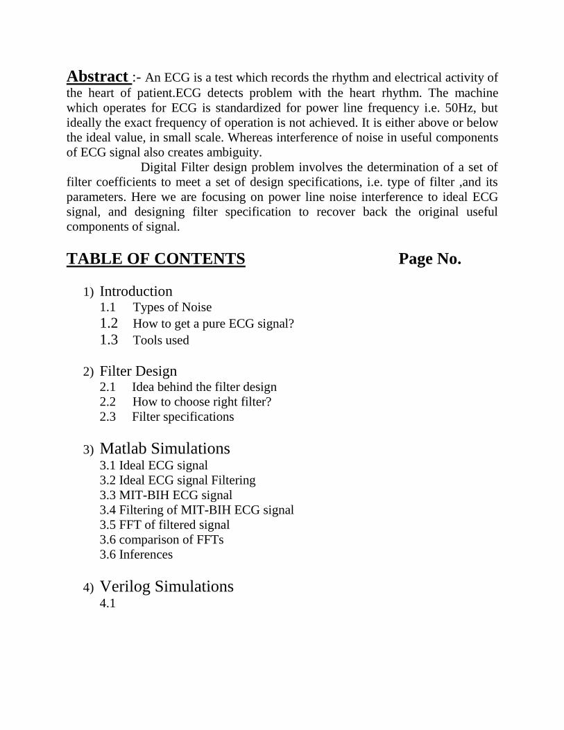
Abstract :- An ECG is a test which records the rhythm and electrical activity of
the heart of patient.ECG detects problem with the heart rhythm. The machine
which operates for ECG is standardized for power line frequency i.e. 50Hz, but
ideally the exact frequency of operation is not achieved. It is either above or below
the ideal value, in small scale. Whereas interference of noise in useful components
of ECG signal also creates ambiguity.
Digital Filter design problem involves the determination of a set of
filter coefficients to meet a set of design specifications, i.e. type of filter ,and its
parameters. Here we are focusing on power line noise interference to ideal ECG
signal, and designing filter specification to recover back the original useful
components of signal.
TABLE OF CONTENTS Page No.
1) Introduction 1.1 Types of Noise
1.2 How to get a pure ECG signal? 1.3 Tools used
2) Filter Design 2.1 Idea behind the filter design
2.2 How to choose right filter?
2.3 Filter specifications
3) Matlab Simulations 3.1 Ideal ECG signal
3.2 Ideal ECG signal Filtering
3.3 MIT-BIH ECG signal
3.4 Filtering of MIT-BIH ECG signal
3.5 FFT of filtered signal
3.6 comparison of FFTs
3.6 Inferences
4) Verilog Simulations
4.1
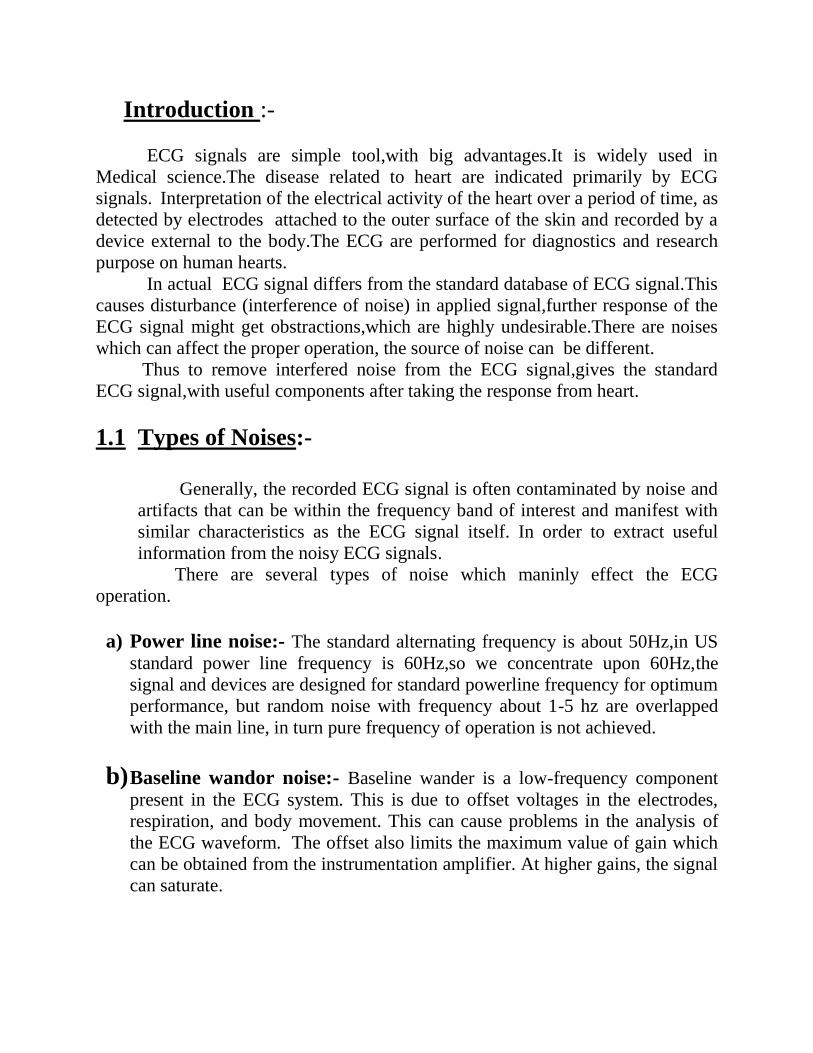
Introduction :-
ECG signals are simple tool,with big advantages.It is widely used in
Medical science.The disease related to heart are indicated primarily by ECG
signals. Interpretation of the electrical activity of the heart over a period of time, as
detected by electrodes attached to the outer surface of the skin and recorded by a
device external to the body.The ECG are performed for diagnostics and research
purpose on human hearts.
In actual ECG signal differs from the standard database of ECG signal.This
causes disturbance (interference of noise) in applied signal,further response of the
ECG signal might get obstractions,which are highly undesirable.There are noises
which can affect the proper operation, the source of noise can be different.
Thus to remove interfered noise from the ECG signal,gives the standard
ECG signal,with useful components after taking the response from heart.
1.1 Types of Noises:-
Generally, the recorded ECG signal is often contaminated by noise and
artifacts that can be within the frequency band of interest and manifest with
similar characteristics as the ECG signal itself. In order to extract useful
information from the noisy ECG signals.
There are several types of noise which maninly effect the ECG
operation.
a) Power line noise:- The standard alternating frequency is about 50Hz,in US
standard power line frequency is 60Hz,so we concentrate upon 60Hz,the
signal and devices are designed for standard powerline frequency for optimum
performance, but random noise with frequency about 1-5 hz are overlapped
with the main line, in turn pure frequency of operation is not achieved.
b) Baseline wandor noise:- Baseline wander is a low-frequency component
present in the ECG system. This is due to offset voltages in the electrodes,
respiration, and body movement. This can cause problems in the analysis of
the ECG waveform. The offset also limits the maximum value of gain which
can be obtained from the instrumentation amplifier. At higher gains, the signal
can saturate.
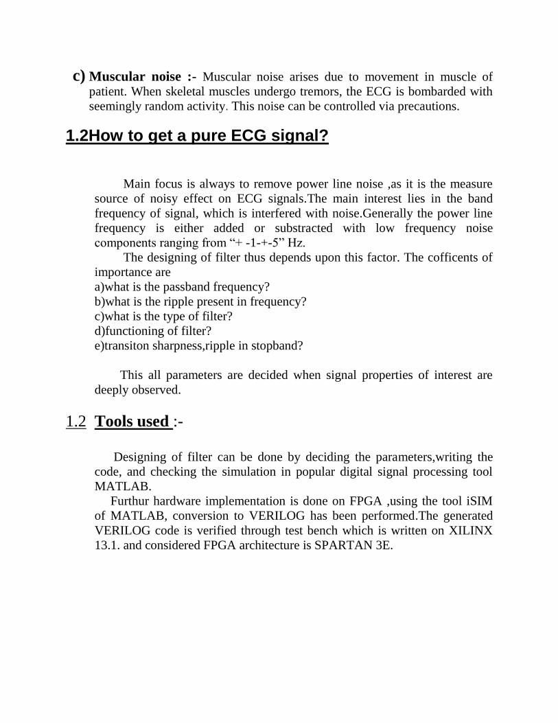
c) Muscular noise :- Muscular noise arises due to movement in muscle of
patient. When skeletal muscles undergo tremors, the ECG is bombarded with
seemingly random activity. This noise can be controlled via precautions.
1.2How to get a pure ECG signal?
Main focus is always to remove power line noise ,as it is the measure
source of noisy effect on ECG signals.The main interest lies in the band
frequency of signal, which is interfered with noise.Generally the power line
frequency is either added or substracted with low frequency noise
components ranging from “+ -1-+-5” Hz.
The designing of filter thus depends upon this factor. The cofficents of
importance are
a)what is the passband frequency?
b)what is the ripple present in frequency?
c)what is the type of filter?
d)functioning of filter?
e)transiton sharpness,ripple in stopband?
This all parameters are decided when signal properties of interest are
deeply observed.
1.2 Tools used :-
Designing of filter can be done by deciding the parameters,writing the
code, and checking the simulation in popular digital signal processing tool
MATLAB.
Furthur hardware implementation is done on FPGA ,using the tool iSIM
of MATLAB, conversion to VERILOG has been performed.The generated
VERILOG code is verified through test bench which is written on XILINX
13.1. and considered FPGA architecture is SPARTAN 3E.

2 Filter design
2.1 Idea behind the filter design:-
It can be understood by the flow chart.
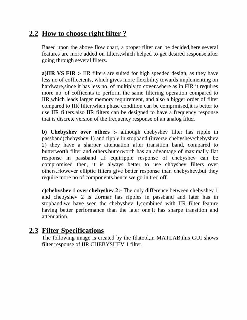
2.2 How to choose right filter ?
Based upon the above flow chart, a proper filter can be decided,here several
features are more added on filters,which helped to get desired response,after
going through several filters.
a)IIR VS FIR :- IIR filters are suited for high speeded design, as they have
less no of cofficeients, which gives more flexibility towards implementing on
hardware,since it has less no. of multiply to cover.where as in FIR it requires
more no. of cofficents to perform the same filtering operation compared to
IIR,which leads larger memory requirement, and also a bigger order of filter
compared to IIR filter.when phase condition can be comprmised,it is better to
use IIR filters.also IIR filters can be designed to have a frequency response
that is discrete version of the frequency response of an analog filter.
b) Chebyshev over others :- although chebyshev filter has ripple in
passband(chebyshev 1) and ripple in stopband (inverse chebyshev/chebyshev
2) they have a sharper attenuation after transition band, compared to
butterworth filter and others.butterworth has an advantage of maximally flat
response in passband .If equiripple response of chebyshev can be
compromised then, it is always better to use chbyshev filters over
others.However elliptic filters give better response than chebyshev,but they
require more no of components.hence we go in tred off.
c)chebyshev 1 over chebyshev 2:- The only difference between chebyshev 1
and chebyshev 2 is ,formar has ripples in passband and later has in
stopband.we have seen the chebyshev 1,combined with IIR filter feature
having better performance than the later one.It has sharpe transition and
attenuation.
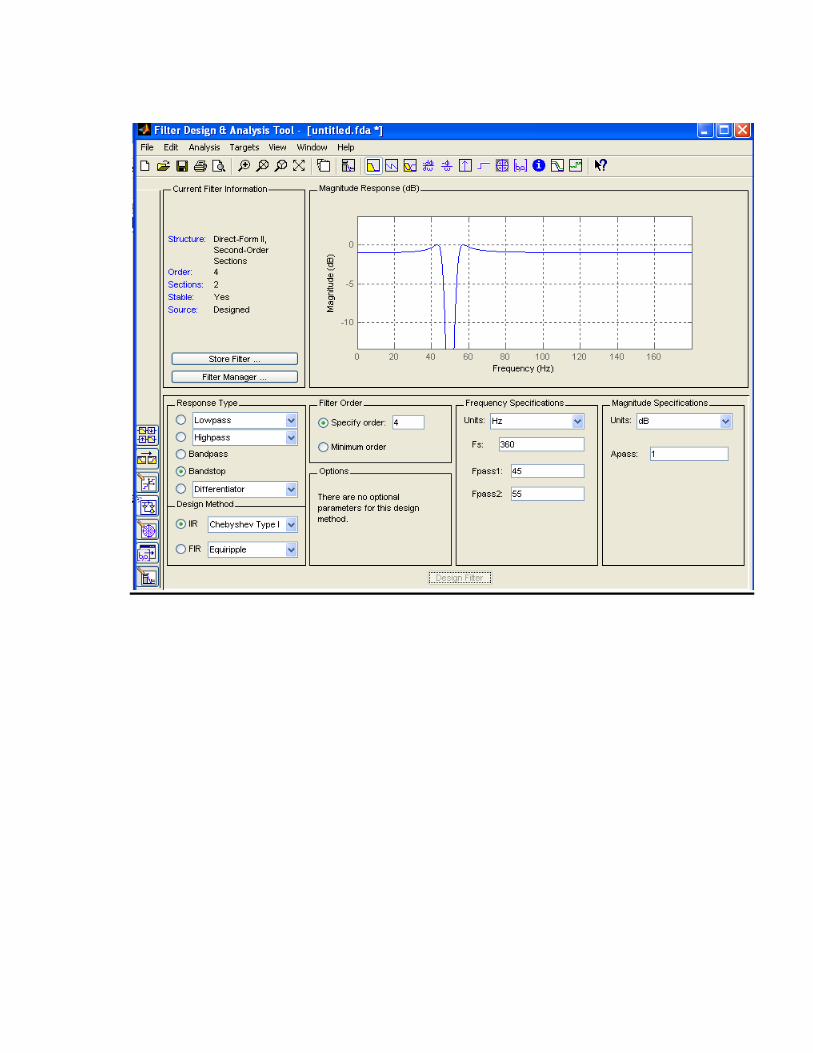
2.3 Filter Specifications The following image is created by the fdatool,in MATLAB,this GUI shows
filter response of IIR CHEBYSHEV 1 filter.