ECE/TRANS/180/Add€¦ · Web viewECE/TRANS/180/Add.12/Appendix 1 ... The word start must appear...
75
ECE/TRANS/180/Add.12/Appendix 1 30 April 2012 Global Registry Created on 18 November 2004, pursuant to Article 6 of the Agreement concerning the establishing of global technical regulations for wheeled vehicles, equipment and parts which can be fitted and/or be used on wheeled vehicles (ECE/TRANS/132 and Corr.1) done at Geneva on 25 June 1998 Addendum Global technical regulation No. 12 Global technical regulation concerning uniform provisions for location and identification of motorcycle controls, tell-tales and indicators (Established in the Global Registry on 17 November 2011) Appendix Proposal and report pursuant to Article 6, paragraph 6.2.7. of the Agreement - Proposal to develop a global technical regulation concerning uniform provisions for location and identification of motorcycle controls, tell-tales and indicators (ECE/TRANS/WP.29/AC.3/22) - Report on the development of a global technical regulation concerning uniform provisions for location and identification of motorcycle controls, tell-tales and indicators (ECE/TRANS/WP.29/2011/141 as amended by Annex GE.12-
Transcript of ECE/TRANS/180/Add€¦ · Web viewECE/TRANS/180/Add.12/Appendix 1 ... The word start must appear...

ECE/TRANS/180/Add.12/Appendix 1
30 April 2012
Global Registry
Created on 18 November 2004, pursuant to Article 6 of the Agreement concerning the establishing of global technical regulations for wheeled vehicles, equipment and parts which can be fitted and/or be used on wheeled vehicles (ECE/TRANS/132 and Corr.1) done at Geneva on 25 June 1998
Addendum
Global technical regulation No. 12
Global technical regulation concerning uniform provisions for location and identification of motorcycle controls, tell-tales and indicators
(Established in the Global Registry on 17 November 2011)
Appendix
Proposal and report pursuant to Article 6, paragraph 6.2.7. of the Agreement
- Proposal to develop a global technical regulation concerning uniform provisions for loc-ation and identification of motorcycle controls, tell-tales and indicators (ECE/TRANS/WP.29/AC.3/22)
- Report on the development of a global technical regulation concerning uniform provi-sions for location and identification of motorcycle controls, tell-tales and indicators (ECE/TRANS/WP.29/2011/141 as amended by Annex III of ECE/TRANS/WP.29/1093), adopted by AC.3 at its twenty-fifth session (ECE/TRANS/WP.29/1072, para. 100)
GE.12-

ECE/TRANS/180/Add.12/Appendix 1
UNITED NATIONS
Global technical regulation concerning uniform provisions for location and identification of motorcycle controls, tell-tales and indicators
I. Objective of the proposal
1. Many vehicle collisions result from driver distraction. One identifiable source of such distraction is diversion of drivers' attention from the driving task by confusing information displayed in the drivers' field of vision and unclear identification of the controls necessary for vehicle's operation.
2. People purchasing new vehicles in countries allowing motorcycles certified in different jurisdictions are faced with different tell-tales and means of identifying controls. Drivers need time to learn their dashboard messages and to identify their vehicle controls. During this time these vehicle operators have to divide their attention between the increasingly difficult task of driving, the identification of controls and the comprehension of tell-tales provided to "ease" the driving task.
3. There is, therefore, a need to harmonize the way in which the motorcycle controls, tell-tales and indicators are installed and identified.
4. The proposed global technical regulation would apply to all on-road motorcycles. It would specify requirements for the location, identification, colour, and illumination of motorcycle tell-tales, indicators and controls. It would be designed to ensure the visibility of tell-tales and indicators and to ensure the accessibility of vehicle controls to facilitate their selection under daylight and night-time conditions.
II. Description of the proposed regulation
5. The document attached as Annex 1 is a table which compares the content of the texts listed below and includes a draft proposal for the technical content of the global technical regulation.
III. Existing regulations and directives
6. Though there are no regulations currently contained in the Compendium of Candidates, the following regulations were taken into account during development of the new global technical regulation regarding controls, tell-tales and indicators:
2
ECE/TRANS/180/Add.12/Appendix 1
(a) Canada Motor Vehicle Safety Regulation No. 101 – Location and identification of controls and displays.
(b) EC Directive 93/29/EEC – Identification of controls, tell-tales and indicators
(c) Japan: Article 10/Article 46.
(d) UNECE Regulation No. 60: Controls, tell-tales and indicators
(e) U.S.A Federal Motor Vehicle Standard 123: Controls and displays.
IV. International voluntary standards
(a) ISO 6727-1981 "Motorcycles: Symbols for control indicators and tell-tales
(b) 9021-1988 "Motorcycles - Controls - Types, positions and functions
3

EC
E/T
RA
NS/180/A
dd.12/Appendix 1
6
Annex 1
COMPARISON BETWEEN CURRENT REGULATIONS AND STANDARDS
Item Source FMVSS ISO ISO JAPAN EU 1958 Agreement IMMA Proposal
No. Contents 123 6727-1981 9021-1988 Article 10 / Article 46 93/29/EEC Regulation No. 60 gtr Comments
Subject Contents Motorcycle Controls and Displays.
Rode Vehicles - Motorcycles - Symbols for controls, indicators and tell-tales
Motorcycles - Controls - Types, positions and functions.
Control Systems(Article 10)Speedometer(Article 46).
Requirements concerning the component type-approval of two or three-wheel vehicles in respect of the identification of their controls, tell-tales and indicators.
Uniform Provisions concerning the approval of two-wheeled motor-cycles and mopeds with regards to driver operated controls including the identification of controls, tell-tale and indicators.
Motorcycle Controls, Dis-plays and Symbols.
Vehicle Application
Source 2 1 1
Contents Motorcycle equipped with handlebars, except law enforcement motorcycles.
Motorcycles as defined in ISO 3833. Controls that are fitted to the instrument panel or are in the immediate vicinity of the motorcycle driver.
Two-wheeled motorcycles as defined in ISO 3833.
Motor vehicles.
Two or three wheeled motor vehicles.
Two wheeled motorcycles and two wheeled mopeds.
Motorcycles used on Public Roads .
This is to be addressed at a later date, once the category definitions are further agreed upon.

EC
E/T
RA
NS/180/A
dd.12/Appendix 133
Item Source FMVSS ISO ISO JAPAN EU 1958 Agreement IMMA Proposal
No. Contents 123 6727-1981 9021-1988 Article 10 / Article 46 93/29/EEC Regulation No. 60 gtr Comments
General Requirements
Source S3. 4.2. Article 10-1 5.1. Contents Any identification
provided shall be placed on or adjacent to the control or display position, and shall appear upright to the operator.
Controls shall be within the driver's reach while in normal driving position. Controls on the handlebars shall be placed so that the driver's hand does not leave the respective handgrip. All controls shall be reachable without any other controls or parts of the structure being in the way.
Control devices that are necessary for operating a motor vehicle shall be located 500 mm or less to the left and right of the center of the steering wheel and be constructed so that the driver, in normal driving position, may easily operate them.
Controls shall be within the driver's reach while in normal driving position. Controls on the handlebars shall be placed so that the driver's hand does not leave the respective handgrip. All controls shall be reachable without any other controls or parts of the structure being in the way.
Controls used during normal operations shall be within the operator's reach while in the normal operating position. Controls on the handlebars shall be placed so that when used, the operator's hand does not leave the respective handgrip. Symbols or displays for controls viewed by the operator while in the normal operating position shall stand out clearly against the background, either bright against dark or dark against bright. Symbols must be placed on or adjacent to the control or display to be identified. Where this is not possible, the symbol and the control or display must be joined by a continuous line as short as possible.
Source 4.1. Article 10-2 2.1. Contents Symbols must be
such that, when viewed by the driver, from his normal seat position, they are recognizable.
Identification shall be placed on or nearby so as to be easily recognized by the driver in his seat.
The controls, tell-tales and indicators referred to in section 2.1.5. shall be identified in accordance with the following requirements when they are fitted to a vehicle.
Source 4.2. 2.1.1. Contents Symbols on
controls and tell-tales shall have a good contrast with their background.
These symbols shall stand out clearly against the background, either bright against dark or dark against bright.
5

EC
E/T
RA
NS/180/A
dd.12/Appendix 1
6
Item Source FMVSS ISO ISO JAPAN EU 1958 Agreement IMMA Proposal
No. Contents 123 6727-1981 9021-1988 Article 10 / Article 46 93/29/EEC Regulation No. 60 gtr Comments
Source 4.3. 2.1.2.
Contents Symbols must be placed on, or adjacent to, the control or tell-tale to be identified. Where this is not possible, the symbol and the control or tell-tale must be joined by a continuous line as short as possible.
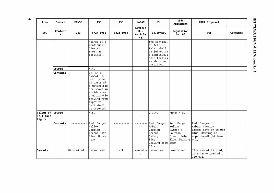
The symbols shall be placed on the control or control tell-tale to be identified or in immediate proximity thereof. Where this is not possible the symbol and the control, or tell-tale, shall be joined by a continuous dash that is as short as possible.
Source 4.4. Contents If, in a symbol, a
motorcycle or parts of a motorcycle are shown in a side view, a motorcycle driving from right to left shall be assumed.
Colour of Tell-Tale Lights
Source ---------- 4.6. ---------- ---------- 2.1.4. Annex 4 8.
Contents ---------- Red: DangerYellow: CautionGreen: SafeBlue: Upper beam
---------- ---------- Red: DangerAmber: CautionGreen: SafetyBlue: Driving beam only
Red: DangerYellow (Amber): CautionGreen: SafeBlue: Driving beam
Red: DangerAmber: CautionGreen: Safe or In Use Blue: Driving or upper headlight beam only
Symbols Harmonized Harmonized N/A Harmonized Harmonized Harmonized If a symbol is used, it's harmonized with ISO 6727

EC
E/T
RA
NS/180/A
dd.12/Appendix 133
Item Source FMVSS ISO ISO JAPAN EU 1958 Agreement IMMA Proposal
No. Contents 123 6727-1981 9021-1988 Article 10 / Article 46 93/29/EEC Regulation No. 60 gtr Comments
Supplemental Engine Stop Control
Source S5.1. & Table 3 No. 2
---------- 5.1.3.1. & 5.1.3.2. ---------- 2.1.5., Fig. 13, Fig. 14
6.1.3.1.
Contents Each motorcycle shall be equipped with it located on the right handlebar, represented by given symbols and the wording" off, run".
---------- May be equipped with an electrical power cut-out.Position: on handlebars, right side.Manual decompression controlPosition: on handlebars.Type: lever, or rotating handgrip, provided that it is combined with the speed control.
---------- Diesel engine ignition or cut-off control in 'out of use' positionDiesel engine ignition or cut-off control in the 'operating' position.
May be equipped.Alternative to the main switch or decompression valve control, located on the right side of the handlebars.Represented by given symbols for "off" and "run".
Located on the right handlebar, represented by given words and/or symbols for "off " and "on" or "run" positions.
Source Table 3 No. 2 5.13. ---------- ---------- Fig. 13 & Fig. 14 Fig. 15A, B Symbol
or
---------- ----------
Colour of tell-tale
---------- ---------- ---------- ---------- ---------- ----------
Ignition Switch
Source Table 1 No. 6 Table 3 No. 1
---------- 5.1.1.1. ---------- ---------- 6.1.1.1.
Contents Off - will appear when at appropriate position, counter clockwise from other positions
---------- For a rotary switch, motion shall be clockwise from the ignition "off" position to the "on" position.
---------- ---------- For a rotary switch, motion shall be clockwise from the ignition "off" position to the "on" position.
Definition: Ignition Switch - The device that enables the engine to run, and may also allow operation of other electrical systems on a vehicle.For a rotary control, the "on" position shall be clockwise from the "off" position.
7
OffO
R
Eng
Run
Off
RunOperating
Out of use Off
On or
Run
Off
Run
Engin stop
EC
E/T
RA
NS/180/A
dd.12/Appendix 1
6
Item Source FMVSS ISO ISO JAPAN EU 1958 Agreement IMMA Proposal
No. Contents 123 6727-1981 9021-1988 Article 10 / Article 46 93/29/EEC Regulation No. 60 gtr Comments
Symbol Ignition ---------- ---------- ---------- ---------- ----------
Colour of tell-tale
---------- ---------- ---------- ---------- ---------- ----------

EC
E/T
RA
NS/180/A
dd.12/Appendix 133
Item Source FMVSS ISO ISO JAPAN EU 1958 Agreement IMMA Proposal
No. Contents 123 6727-1981 9021-1988 Article 10 / Article 46 93/29/EEC Regulation No. 60 gtr Comments
Electric Starter
Source Table 3 No. 4 ---------- 5.1.1.2. & 5.1.1.3. Article 10-1 2.1.5. 6.1.1.2. & 6.1.1.3.
Contents Represented by a given symbol.The word start must appear when at appropriate position if separate from ignition switch.
---------- No special requirement.In the case of a rotary switch, motion shall be clockwise, passing from ignition "off" to ignition "on" and then to the starter energizing position.
Control devices that are necessary for operating a motor vehicle shall be located 500 mm or less to the left and right of the center of the steering wheel and be constructed so that the driver, in normal driving position, may easily operate them.
Represented by a given symbol.
No special requirement.In the case of a rotary switch, the direction of motion shall be clockwise, passing from the "off" position to the ignition "on" position to the starter energizing position.
Represented by a given symbol.
Source Table 3 No. 4 5.16. ---------- ---------- Fig. 19 Fig. 18
Symbol ---------- ----------
Colour of tell-tale
---------- ---------- ---------- ---------- ---------- ----------
Manual Choke
Source Table 3 No. 3 ---------- 5.5.1. ---------- 2.1.5. 6.5.1. & 9.
Contents Represented by a given symbol and the wording "Choke [or enricher] or the required symbol".
---------- Needs to be placed as to be reasonable and conveniently accessible to the driver.
---------- Represented by a given symbol.
The control shall be so placed as to be reasonably and conveniently accessible to the rider.
Represented either by the symbol on the control or an optional amber tell-tale with the symbol.
Source Table 3 No. 3 5.4. ---------- ---------- Fig. 5 Fig. 5
Symbol ---------- ----------
Colour of tell-tale
---------- ---------- ---------- ---------- Amber Amber Amber
9
Choke or Enricher
Start

EC
E/T
RA
NS/180/A
dd.12/Appendix 1
6
Item Source FMVSS ISO ISO JAPAN EU 1958 Agreement IMMA Proposal
No. Contents 123 6727-1981 9021-1988 Article 10 / Article 46 93/29/EEC Regulation No. 60 gtr Comments
Neutral Indicator
Source Table 3 No. 9Table 2 No. 2
---------- ---------- ---------- 2.1.5. 9.
Contents Represented by a given symbol and the wording "Neutral" by a green display lamp that illuminates when the gear selector is in the neutral position.
---------- ---------- ---------- Represented by a given symbol.
Represented by a given symbol.
Represented by a given symbol, green tell-tale light.
Source Table 3 No. 9 5.15. ---------- ---------- Fig. 18 Fig. 17
Symbol ---------- ----------
Colour of tell-tale
Green Green ---------- ---------- Green Green Green
Fuel Tank Shutoff Valve
Source Table 3 No. 12 5.12. 5.5.2.1. ---------- ---------- 6.5.2. & 9.
Manual Contents Represented by the wording "Fuel" and given symbols for three positions, "on, off, reserve", which are separated by 90 degrees of rotation.The framed areas may be solid. (On and Reserve)
The framed areas may be solid. (On and Reserve)
The control shall have separate positions for "off", "on" and "reserve" (where a reserve supply is provided).The control shall be "on" when the fuel-flow points downstream from the fuel-tank to the engine: it shall be "off" when it is perpendicular to fuel-flow: it shall be on "reserve" (when applicable) when it points upstream of the fuel-flow.
---------- ---------- The control shall have separate positions for "OFF", "ON" and "RESERVE" (where a reserve supply is provided).The control shall be in the ON position when it is in the direction downstream of the flow of fuel from the tank to the engine: in the OFF position when it is in a direction perpendicular to the flow of fuel, and in the RESERVE position (where applicable) when it is in the direction upstream of the flow of fuel.
If so equipped, the "on" position shall be separated from the "off" position by 90 degrees of rotation. If equipped with a "reserve" position, it shall be separated from the "on" position by 180 degrees of rotation and the operator shall be able to switch to the "reserve" position while in the normal driving position. Optional: the switch may be represented by the words "On" "Off" and "Reserve" (or "Res" or "Res."), or by the given symbols.
Neutral

EC
E/T
RA
NS/180/A
dd.12/Appendix 133
Item Source FMVSS ISO ISO JAPAN EU 1958 Agreement IMMA Proposal
No. Contents 123 6727-1981 9021-1988 Article 10 / Article 46 93/29/EEC Regulation No. 60 gtr Comments
Source ---------- ---------- 5.5.2.2. ---------- ---------- 6.5.2.1. Contents ---------- ---------- Where a reserve
supply is provided, the driver shall be able to switch to it while seated in the driving position.
---------- ---------- Where a machine is so equipped the rider must be able to switch to the reserve fuel supply when in the seated position.
Source Table 3 No. 12 5.12. ---------- ---------- ---------- Fig. 13 & Fig. 14
Symbol ---------- ---------- ----------
Colour of tell-tale
---------- ---------- ---------- ---------- ---------- ----------
Automatic Contents Fuel shut-off control optional for systems in which the fuel flow is stopped when the engine is switched off. If equipped with a control, the symbols and control positions shall be the same as identified for Manual Fuel Shut-Off Control. No "Off" position is required. The control may include a "Prime" position which shall not conflict with any other defined position and shall be marked with the "PRI": .
There is currently no symbol for the "Prime" function. A new appropriate symbol could be discussed as a future work item, e.g. in ISO, etc.
11
Off
On
Res.
Off
On
Reserve
Off
Res.
Off
On
Reserve
or Res.
or Res

EC
E/T
RA
NS/180/A
dd.12/Appendix 1
6
Item Source FMVSS ISO ISO JAPAN EU 1958 Agreement IMMA Proposal
No. Contents 123 6727-1981 9021-1988 Article 10 / Article 46 93/29/EEC Regulation No. 60 gtr Comments
Speedometer Source Table 3 No. 8 ---------- ---------- Article 46 & Instruction
---------- ----------
Contents Illuminated whenever the headlamp is activated. M.P.H. increases clockwise with 10 mph intervals for numerals and major graduations, 5 mph intervals for minor graduations.
---------- ---------- Shall be constructed so that the driver may easily confirm the speed while the motor vehicle is moving.Shall have a lighting device or be luminous or shall have luminous dial plate or pointer.Shall be glare proof. Shall be shown in km/h.Motor driven two wheeled vehicles with speed over 30 km/h must have speed warning indicator lamp.
---------- N/AECE R.39200 km/h >= Interval 20 km/h >=>200 km/h Interval 30 km/h >=
The speedometer display must be located within the direct field of view of the driver and shall be legible day or night.
Symbol ---------- ---------- ---------- ---------- ---------- ---------- Colour of
tell-tale ---------- ---------- ---------- ---------- ---------- ----------

EC
E/T
RA
NS/180/A
dd.12/Appendix 133
Item Source FMVSS ISO ISO JAPAN EU 1958 Agreement IMMA Proposal
No. Contents 123 6727-1981 9021-1988 Article 10 / Article 46 93/29/EEC Regulation No. 60 gtr Comments
Horn Source Table 3 No. 6Table 1 No. 4
---------- 5.4.1. Article 10-1 2.1.5. 6.4.1. & 9.
Contents Represented by a given symbol or the wording "Horn "located on the left handlebar, push to activate.
---------- Button or switch located on the left handlebar.For vehicles with gear selection operated in conjunction with a hand -operated clutch, button or switch located on the right handlebar.
Control devices that are necessary for operating a motor vehicle shall be located 500 mm or less to the left and right of the center of the steering wheel and be constructed so that the driver, in normal driving position, may easily operate them.
Represented by a given symbol.
For gear selection independent of the clutch: button on the left handlebar.For gear selection in conjunction with the clutch: button on the right handlebar.Represented by a given symbol.
Represented by a given symbol, located on the left handlebar for vehicles with foot operated gear selection operated independently of the clutch and on the right handlebar for vehicles with gear selection operated in conjunction with the clutch.
Source Table 3 No. 6 5.5. ---------- Article 10-2 Fig. 6 Fig. 6
Symbol
or
---------- Identification shall be placed on or nearby so as to be easily recognized by the driver in his seat.(JIS D0032 or ISO2575 as sample)
Colour of tell-tale
---------- ---------- ---------- ---------- ---------- ----------
13
Horn

EC
E/T
RA
NS/180/A
dd.12/Appendix 1
6
Item Source FMVSS ISO ISO JAPAN EU 1958 Agreement IMMA Proposal
No. Contents 123 6727-1981 9021-1988 Article 10 / Article 46 93/29/EEC Regulation No. 60 gtr Comments
Headlamps Source Table 3 No. 5Table 3 No. 10Table 1 No. 3
5.1. 5.4.2.2. 2.1.3.2.1.5.
6.4.2.2.1.9.
Contents Represented by a given symbols and the wording" Hi, Low" located on the left handlebar, up for high beam and down for low beam. The framed areas may be solid.
The framed areas may be solid.
For vehicles with gear selection operated by a foot lever and/or independent of the clutch: located on the left handlebar. Located on the right handlebar for vehicle with gear selection operated in conjunction with the clutch.
Must be located within 500 mm to the center of the steering wheel and can be operated by the driver easily while driving.
Main beam headlights shall be represented by parallel horizontal rays of light and dipped beam headlamps by parallel rays of light angled downwards.
Vehicle with gear selection operated independently of the clutch: located on the left handlebar.
Located on the left handlebar for vehicles with gear selection operated independently of a hand operated clutch, on right handlebar for vehicles with gear selection is operated in conjunction with the hand operated clutch. Represented by given symbols for driving beam headlamp and passing beam headlamp. An indicator lamp shall show when the driving beam is in use.
Source ---------- ---------- ---------- ---------- ---------- 6.4.2.2.2. Contents ---------- ---------- ---------- ---------- ---------- Located on the right
handlebar for the vehicle with gear selection operated in conjunction with the clutch.
Source Table 3 No. 5, No. 10
5.1. ---------- ---------- Fig. 1 & Fig. 2. Fig. 1 & Fig. 2
Symbol Lights
or High beam
Main beam
Dipped beam
---------- ---------- Main beam
Dipped beam
Colour of tell-tale
---------- Blue (Main beam) ---------- ---------- Blue (Main beam)Green (Dipped beam)
Blue (Main beam)-----------------------
Driving or High Beam: Blue. Optional: Passing or Low Beam: Green.
Lights
Hig
Drivingbeam
Passingbeam
Drivingbeam
Passing beam

EC
E/T
RA
NS/180/A
dd.12/Appendix 133
Item Source FMVSS ISO ISO JAPAN EU 1958 Agreement IMMA Proposal
No. Contents 123 6727-1981 9021-1988 Article 10 / Article 46 93/29/EEC Regulation No. 60 gtr Comments
Optical Warning Device
Source ---------- ---------- 5.4.2.3. ---------- ---------- 6.4.2.3.
Contents ---------- ---------- The control for this device, for which there is no special requirement as to type, shall be adjacent to the main-beam/dipped-beam switch or an additional function of it.
---------- ---------- The control for this device shall be adjacent to the Driving Beam/Passing Beam Switch or shall be an additional function of the latter.
If so equipped, the control for this device shall be located on the same handlebar as the vehicle Driving Beam/Passing Beam Switch.
Colour of tell-tale
---------- ---------- ---------- ---------- ---------- ----------
Fog Lamps Source ---------- ---------- ---------- 2.1.5. 9.
Contents ---------- If one control is used for both, front fog lamp symbol is used.The framed areas may be solid. (Front)
---------- ---------- Represented by a given symbols for front and rear fog lamps.If one control is used for both, front fog lamp symbol is used.
Represented by a given symbol for front and rear fog lamps.If one control is used for both, front fog lamp symbol is used.
Represented by given symbols for front and rear fog lamps.If one control is used for both, front fog lamp symbol is used.
Source ---------- 5.10. & 5.11. ---------- ---------- Fig. 10 & Fig. 11 Fig. 10 & Fig. 11
Symbol ---------- ---------- ----------
Colour of tell-tale
---------- Front: Green Rear: Amber
---------- ---------- Front: Green Rear: Amber
Front: Green Rear: Amber
Front: Green. Rear: Amber. If one lamp is used for both: Green.
15
Front
Rear
Front
Rear
Front
Rear
Front
Rear

EC
E/T
RA
NS/180/A
dd.12/Appendix 1
6
Item Source FMVSS ISO ISO JAPAN EU 1958 Agreement IMMA Proposal
No. Contents 123 6727-1981 9021-1988 Article 10 / Article 46 93/29/EEC Regulation No. 60 gtr Comments
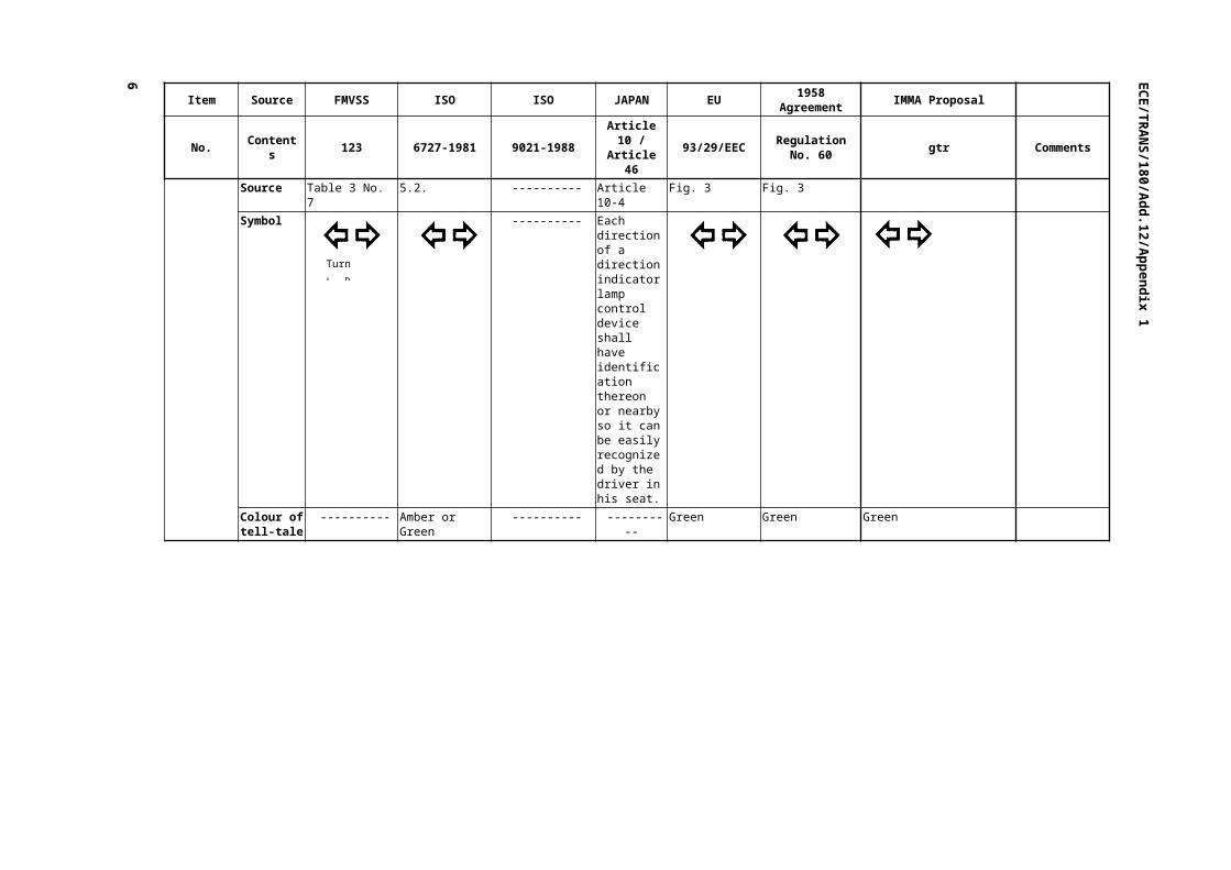
Turn Signal Source Table 3 No. 7 5.2. 5.4.3. Article 10-1 2.1.5. 6.4.3. & 9. Contents Represented by a
given symbols or the wording "Turn, L, R".Control located on the handlebars.The framed areas may be solid.
The framed areas may be solid.
Position: on handlebarsThe control shall be so designed that, when viewed from the driver's seat, operation, of the left-hand portion, or movement to the left actuates the left side direction indicators and the inverse for the right side direction indicators.The control shall be clearly marked to show the side of the vehicle on which the indicators are working.
Control devices that are necessary for operating a motor vehicle shall be located 500 mm or less to the left and right of the center of the steering wheel and be constructed so that the driver, in normal driving position, may easily operate them.
Represented by given symbols.
The control shall be so designed that, when viewed from the rider's seat operation of the left hand position, or movement to the left of the control actuates the left side indicators and vice versa for the right side indicators.The control shall clearly be marked in such a manner as to indicate the side of the vehicle on which the control actuates the indicators.
Represented by given symbols. The left and right arrows on switches or tell-tales may be separated. Switch is to be located on the handlebar in clear view from the operator's seat and shall be marked clearly. The indicator lamp must be located within the clear view of the operator when the vehicle is in operation and may either flash to show that a turn signal is engaged or separate lamps may flash to show which side of the vehicle is being worked. If there are separate tell-tales, or controls, for the left and right direction indicators, the two arrows may also be used separately.
Source Table 3 No. 7 5.2. ---------- Article 10-4 Fig. 3 Fig. 3 Symbol ---------- Each direction
of a direction indicator lamp control device shall have identification thereon or nearby so it can be easily recognized by the driver in his seat.
Colour of tell-tale
---------- Amber or Green ---------- ---------- Green Green Green
Turn L, R

EC
E/T
RA
NS/180/A
dd.12/Appendix 133
Item Source FMVSS ISO ISO JAPAN EU 1958 Agreement IMMA Proposal
No. Contents 123 6727-1981 9021-1988 Article 10 / Article 46 93/29/EEC Regulation No. 60 gtr Comments
Hazard Warning Light
Source ---------- 5.3. ---------- ---------- 2.1.5. 9.
Contents ---------- The framed areas may be solid.
---------- ---------- Two possibilities:- identifying signal placed alongside or - simultaneous operation of direction indicators (both arrows in Fig. 3).
Represented by either arrows flashing simultaneously, or a triangle symbol.
Represented by either the turn signal indicator lamp(s) flashing simultaneously, or by a given triangle symbol.
Source ---------- 5.3. ---------- ---------- Fig. 4 Fig. 4
Symbol ---------- 1. Simultaneous operation of both arrows of Turn signal
or
2.
---------- ---------- 1. Simultaneous operation of both arrows of Turn signal
or
2.
1. Simultaneous operation of both arrows of Turn signal
or
2.
1. If the tell-tale for a turn signal is the separate, individual arrow (not both arrows), the hazard warning tell-tale may be the simultaneous operation of both turn signal tell-tales
or
2.
Colour of tell-tale
---------- 1. Amber or Green2. Red
---------- ---------- 1 Green2. Red
1. Green2. Red
1. Green 2. Red
17

EC
E/T
RA
NS/180/A
dd.12/Appendix 1
6
Item Source FMVSS ISO ISO JAPAN EU 1958 Agreement IMMA Proposal
No. Contents 123 6727-1981 9021-1988 Article 10 / Article 46 93/29/EEC Regulation No. 60 gtr Comments
Lighting Control Switch
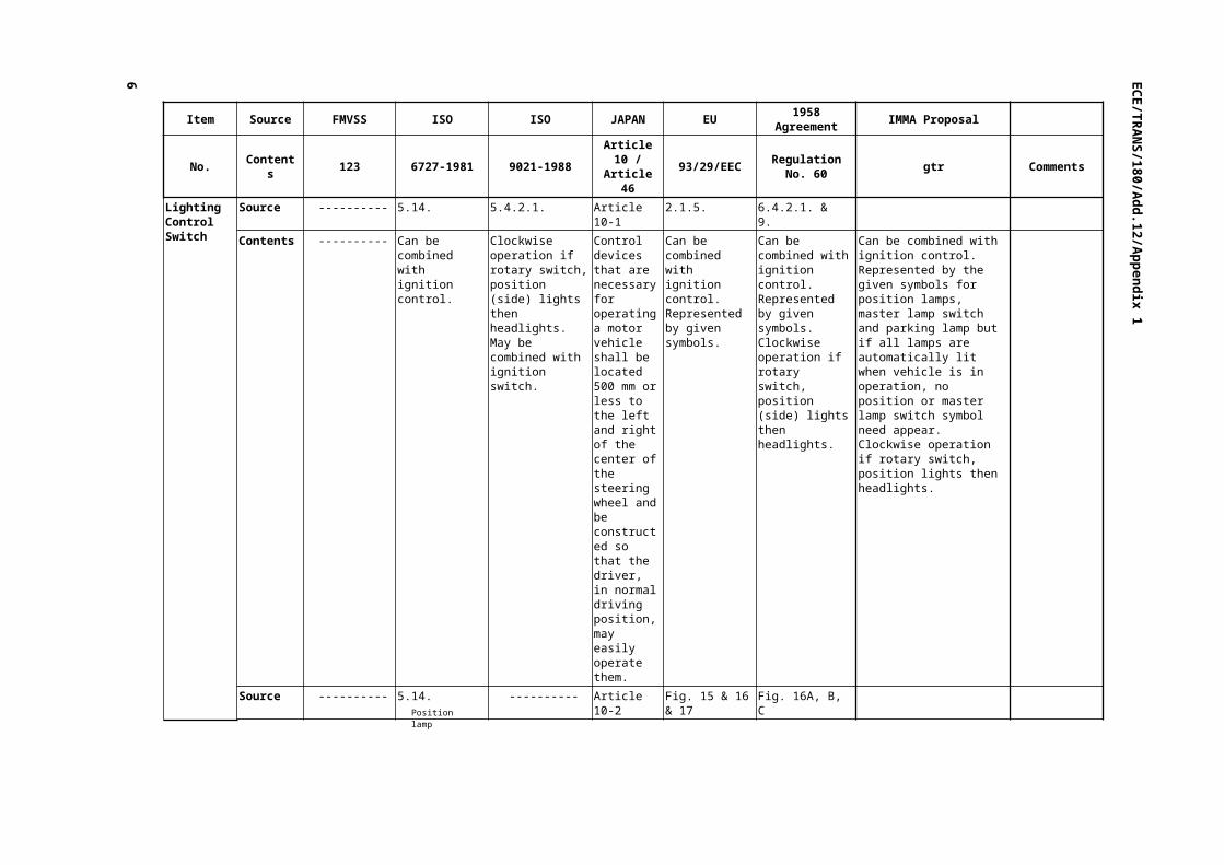
Source ---------- 5.14. 5.4.2.1. Article 10-1 2.1.5. 6.4.2.1. & 9.
Contents ---------- Can be combined with ignition control.
Clockwise operation if rotary switch, position (side) lights then headlights.May be combined with ignition switch.
Control devices that are necessary for operating a motor vehicle shall be located 500 mm or less to the left and right of the center of the steering wheel and be constructed so that the driver, in normal driving position, may easily operate them.
Can be combined with ignition control.Represented by given symbols.
Can be combined with ignition control.Represented by given symbols.Clockwise operation if rotary switch, position (side) lights then headlights.
Can be combined with ignition control. Represented by the given symbols for position lamps, master lamp switch and parking lamp but if all lamps are automatically lit when vehicle is in operation, no position or master lamp switch symbol need appear. Clockwise operation if rotary switch, position lights then headlights.
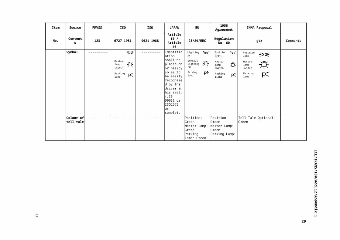
Source ---------- 5.14. ---------- Article 10-2 Fig. 15 & 16 & 17 Fig. 16A, B, C
Symbol ---------- ---------- Identification shall be placed on or nearby so as to be easily recognized by the driver in his seat.(JIS D0032 or ISO2575 as sample).
Colour of tell-tale
---------- ---------- ---------- ---------- Position: GreenMaster Lamp: GreenParking Lamp: Green
Position: GreenMaster Lamp: GreenParking Lamp: -------
Tell-Tale Optional: Green
Positionlamp
Parkinglamp
Masterlampswitch
LightingSW
Parkinglamp
General LightingSW
Positionlight
Parkinglight
Masterlampswitch
Positionlamp
Parkinglamp
Masterlampswitch

EC
E/T
RA
NS/180/A
dd.12/Appendix 133
19

EC
E/T
RA
NS/180/A
dd.12/Appendix 1
6
Item Source FMVSS ISO ISO JAPAN EU 1958 Agreement IMMA Proposal
No. Contents 123 6727-1981 9021-1988 Article 10 / Article 46 93/29/EEC Regulation No. 60 gtr Comments
Fuel Indicator
Source ---------- ---------- ---------- ---------- 2.1.5. 9.
Contents ---------- ---------- ---------- ---------- Represented by a given symbol.
Represented by a given symbol.
(Indicator optional) Represented by a given symbol.
Source ---------- 5.6. ---------- ---------- Fig. 7 Fig. 7
Symbol ---------- ---------- ----------
Colour of tell-tale
---------- Amber ---------- ---------- Amber Amber If so equipped: Amber
Engine Cooling Temp
Source ---------- ---------- ---------- ---------- 2.1.5. 9.
Contents ---------- ---------- ---------- ---------- Represented by a given symbol.
Represented by a given symbol.
(Indicator Optional) Represented by a given symbol.
Source ---------- 5.7. ---------- ---------- Fig. 8 Fig. 8
Symbol ---------- ---------- ----------
Colour of tell-tale
---------- Red ---------- ---------- Red Red If so equipped: Red
Battery Charging
Source ---------- ---------- ---------- ---------- 2.1.5. 9.
Contents ---------- ---------- ---------- ---------- Represented by a given symbol.
Represented by a given symbol.
(Indicator Optional) Represented by a given symbol.
Source ---------- 5.8. ---------- ---------- Fig. 9 Fig. 9
Symbol ---------- ---------- ----------
Colour of tell-tale
---------- Red ---------- ---------- Red Red If so equipped: Red

EC
E/T
RA
NS/180/A
dd.12/Appendix 133
Item Source FMVSS ISO ISO JAPAN EU 1958 Agreement IMMA Proposal
No. Contents 123 6727-1981 9021-1988 Article 10 / Article 46 93/29/EEC Regulation No. 60 gtr Comments
Engine Oil Source ---------- 5.9. ---------- ---------- 2.1.5. 9.
Contents ---------- The framed areas may be solid.
---------- ---------- Represented by a given symbol.
Represented by a given symbol.
Represented by a given symbol.
Source ---------- 5.9. ---------- ---------- Fig. 10 Fig. 10
Symbol ---------- ---------- ----------
Colour of tell-tale
---------- Red ---------- ---------- Red Red Red
Speed Control
Source Table 1 No. 8 ---------- 5.1.2.1. Article 10-1 ---------- 6.1.2.1.
Contents Twist-grip throttle located on the right handlebar. Self-closing to idle in a clockwise direction after release of hand.
---------- The speed of the engine shall be adjusted by a hand-operated control.Position: on the handlebar, right side.Type: rotating handgrip.Direction of rotation: anticlockwise to increase speed.
Control devices that are necessary for operating a motor vehicle shall be located 500 mm or less to the left and right of the center of the steering wheel and be constructed so that the driver, in normal driving position, may easily operate them.
---------- The speed of the engine shall be controlled by a hand-operated control.Position: on the handlebar, right side.Type: rotating handgrip.Direction of rotation: anticlockwise to increase speed.
Rotating handgrip on the right handlebar. Anticlockwise manipulation increases speed. The control shall be self-closing to idle in a clockwise direction after release of the hand unless a speed control device is activated.
21

EC
E/T
RA
NS/180/A
dd.12/Appendix 1
6
Item Source FMVSS ISO ISO JAPAN EU 1958 Agreement IMMA Proposal
No. Contents 123 6727-1981 9021-1988 Article 10 / Article 46 93/29/EEC Regulation No. 60 gtr Comments
Front Wheel Brake
Source Table 1 No. 10 ---------- 5.2.1. Article 10-1 ---------- 6.2.1.
Contents Squeeze to engage on the right handlebar.
---------- Hand lever located on the right handlebar, forward.
Control devices that are necessary for operating a motor vehicle shall be located 500 mm or less to the left and right of the center of the steering wheel and be constructed so that the driver, in normal driving position, may easily operate them.
---------- Hand lever located on the right handlebar, forward.
Hand lever located on the right handlebar. However, in the case of vehicles equipped with a combined brake system, the front wheel brake may operate simultaneously with the rear wheel brake when the combined brake system is activated.
Rear Wheel Brake
Foot Rear Wheel Brake Control
Source Table 1 No. 11 ---------- 5.2.2.1. Article 10-1 ---------- 6.2.2.1.
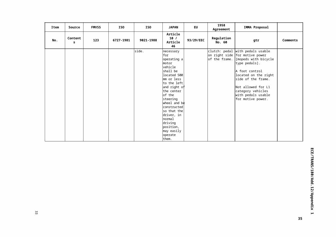
Contents Right foot control. ---------- Hand-operated clutch: pedal, frame, right side.
Control devices that are necessary for operating a motor vehicle shall be located 500 mm or less to the left and right of the center of the steering wheel and be constructed so that the driver, in normal driving position, may easily operate them.
---------- For vehicle with manually operated clutch: pedal on right side of the frame.
For L1 - L5 category vehicles EXCEPT L1 category vehicles with pedals usable for motive power [mopeds with bicycle type pedals].
A foot control located on the right side of the frame.
Not allowed for L1 category vehicles with pedals usable for motive power.

EC
E/T
RA
NS/180/A
dd.12/Appendix 133
Item Source FMVSS ISO ISO JAPAN EU 1958 Agreement IMMA Proposal
No. Contents 123 6727-1981 9021-1988 Article 10 / Article 46 93/29/EEC Regulation No. 60 gtr Comments
Hand Rear Wheel Brake Control
Source ---------- ---------- 5.2.2.2. ---------- ---------- 6.2.2.2.1. Contents ---------- ---------- Without hand-
operated clutch: either hand lever left handlebar, forward or pedal on the frame right side.
---------- ---------- No manual clutch:Hand lever located on the forward left handlebar is a must for vehicles equipped with riding pedal, optional for vehicles that contain platform or footrest integrated into a platform with a max design speed of 100km/h.
For L1 - L5 category vehicles WITHOUT hand operated clutch devices:
A hand control on the left handlebar.
Not allowed for vehicles with hand operated clutch.
Source ---------- ---------- ---------- ---------- 6.2.2.2.2. Contents ---------- ---------- ---------- ---------- No manual clutch:
All other vehicles: pedal frame right side.
Source ---------- ---------- 5.2.3. ---------- ---------- 6.2.3. Contents ---------- ---------- CBS:
Position and type of control: as specified in 5.2.1. or 5.2.2.
---------- ---------- CBS:Position and type of control: as specified in paragraphs 6.2.1. and 6.2.2.
For L1 - L5 category vehicles equipped with combined braking systems.
The rear wheel brake may operate simultaneously with the front wheel brake when the combined brake system is activated.
23

EC
E/T
RA
NS/180/A
dd.12/Appendix 1
6
Item Source FMVSS ISO ISO JAPAN EU 1958 Agreement IMMA Proposal
No. Contents 123 6727-1981 9021-1988 Article 10 / Article 46 93/29/EEC Regulation No. 60 gtr Comments
Parking Brake
Source ---------- ---------- 5.2.4. Article 10-1 ---------- 6.2.4.
Contents ---------- ---------- No special requirement for location or type of control.
Control devices that are necessary for operating a motor vehicle shall be located 500 mm or less to the left and right of the center of the steering wheel and be constructed so that the driver, in normal driving position, may easily operate them.
---------- Hand lever or pedal with no special requirement.
(Optional for three wheeled motorcycles or sidecar equipped motorcycles) Hand or foot control with no special requirements.
Clutch Source Table 1 No. 1 ---------- 5.3.1. Article 10-1 ---------- 6.3.1.
Contents Located on the left handlebar, squeeze to disengage clutch.
---------- Manual operating clutch shall be a hand lever on the left handlebar, forward.Shall not prohibit the use of a combined foot lever for the clutch and gear selection.
Control devices that are necessary for operating a motor vehicle shall be located 500 mm or less to the left and right of the center of the steering wheel and be constructed so that the driver, in normal driving position, may easily operate them.
---------- Hand lever on the left handlebar, forward.Shall not prohibit the use of a combined foot lever for the clutch and gear selection.
If so equipped, a control on the left handlebar, forward. Shall not prohibit the use of devices on the left side of the vehicle that combine operations of a clutch and gear selector.
The IMMA proposal reflects the current and forward looking developments in this area.
With the various new technologies being developed the IMMA proposal is intended to be less design restrictive while still meeting the intent of each of the current applicable regulations.
Hand Levers Source ---------- ---------- A.1.1. Article 10-1 ---------- 1.1.

EC
E/T
RA
NS/180/A
dd.12/Appendix 133
Item Source FMVSS ISO ISO JAPAN EU 1958 Agreement IMMA Proposal
No. Contents 123 6727-1981 9021-1988 Article 10 / Article 46 93/29/EEC Regulation No. 60 gtr Comments
Contents ---------- ---------- At maximum compression the outer end of the hand lever shall not exceed 30mm pass the edge of the handgrip. The distance between the forward face of the hand lever and the rearward face of the handgrip shall not exceed 135 mm or be less than 45 mm.The dimension may decrease inside the mid-point of the hand lever towards the fulcrum, but shall no case be less than 25 mm.
Control devices that are necessary for operating a motor vehicle shall be located 500 mm or less to the left and right of the center of the steering wheel and be constructed so that the driver, in normal driving position, may easily operate them.
---------- The maximum dimension between the forward face of the hand lever and the rearward face of the handgrip shall not exceed 120 mm measured perpendicularly to the axis of the handgrip at any point between the mid-point and the end thereof nearest the fulcrum of the hand lever.In the case of vehicles equipped with a gear selection control operated in conjunction with the clutch operating control, the maximum dimension shall not exceed 135 mm.
To be left out of this document and addressed as necessary with the appropriate systems.
[These items can be identified by the shading in the Item and Source columns of this document]
ECE 60 items covering ergonomic issues (Hand Levers, Foot Rests, Foot Levers, Rocker Arms and Pedals) are not included in this document. It is the belief of IMMA that as these items are fairly design restrictive, they should be removed. As technology evolves, their designs should be governed by market forces and enable targeting specific market segments based on ergonomic efficiencies, or be included in specific system regulations as appropriate.
[These items can be identified by the shading in the Item and Source columns of this document].
25
EC
E/T
RA
NS/180/A
dd.12/Appendix 1
6
Item Source FMVSS ISO ISO JAPAN EU 1958 Agreement IMMA Proposal
No. Contents 123 6727-1981 9021-1988 Article 10 / Article 46 93/29/EEC Regulation No. 60 gtr Comments
Source ---------- ---------- A.1.1.2. ---------- ---------- 1.2.
Contents ---------- ---------- This dimension may increase beyond the mid-point of the handgrip towards the hand lever open end.
---------- ---------- This dimension may increase beyond the mid-point of the handgrip and towards the open end of the hand lever.
Source ---------- ---------- Fig. 1 a) ---------- ---------- Fig. 1 (a)
Fig. ---------- ---------- ---------- ----------
Source ---------- ---------- A.1.2.1. ---------- ---------- 1.3.
Contents ---------- ---------- The minimum dimension (clearance) between the hand lever rearward face and the handgrip forward face shall not be less than 45 mm at any point between the outer end and the mid-point of the handgrip.
---------- ---------- The minimum distance (clearance) between the forward face of the hand lever and the forward face of the handgrip shall not be less than 45 mm at any point between the outer end and the mid-point of the handgrip.
Source ---------- ---------- A.1.2.2. ---------- ---------- 1.4.
Contents ---------- ---------- This dimension may decrease inside the mid-point of the handlever towards the fulcrum, but shall in no case be less than 25 mm.
---------- ---------- This dimension may decrease beyond the mid-point of the handgrip and towards the fulcrum but must in no case be less than 25 mm.

EC
E/T
RA
NS/180/A
dd.12/Appendix 133
Item Source FMVSS ISO ISO JAPAN EU 1958 Agreement IMMA Proposal
No. Contents 123 6727-1981 9021-1988 Article 10 / Article 46 93/29/EEC Regulation No. 60 gtr Comments
Source ---------- ---------- Fig. 1 b) ---------- ---------- Fig. 1 (b)
Fig. ---------- ---------- ---------- ----------
Source ---------- ---------- A.1.3. ---------- ---------- 1.5.
Contents ---------- ---------- The outer end of the hand lever shall not project beyond the outer end of the handgrip by more than 30 mm when the hand lever is at maximum compression.
---------- ---------- The outer end of the hand lever shall not project beyond the outer end of the handgrip by more than 30 mm when the hand lever is in its position of maximum compression.
Source ---------- ---------- Fig. 1 c) ---------- ---------- Fig. 1 (c)
Fig. ---------- ---------- ---------- ----------
Footrest Source 10994 ---------- ---------- ---------- ---------- ----------
Contents Shall be provided for each designated seating position. Passenger footrest shall fold rearward and upward when not in use.
---------- ---------- ---------- ---------- ----------
27
EC
E/T
RA
NS/180/A
dd.12/Appendix 1
6
Item Source FMVSS ISO ISO JAPAN EU 1958 Agreement IMMA Proposal
No. Contents 123 6727-1981 9021-1988 Article 10 / Article 46 93/29/EEC Regulation No. 60 gtr Comments
Foot Lever Source ---------- ---------- A.2.1.1. Article 10-1 ---------- 2.1.1. Contents ---------- ---------- The maximum
distance between the rearward face of the foot lever spur and the rearward face of the footrest shall not exceed 200 mm at any point on the spur.
Control devices that are necessary for operating a motor vehicle shall be located 500 mm or less to the left and right of the center of the steering wheel and be constructed so that the driver, in normal driving position, may easily operate them.
---------- The maximum dimension between the rearward face of the spur of the foot lever and the rearward face of the corresponding footrest shall not exceed 200 mm at any point on the spur.
Source ---------- ---------- A.2.1.2. ---------- 2.1.2. Contents ---------- ---------- The minimum
distance between the rearward face of the foot lever spur and the forward face of the footrest shall not be less than 105 mm at any point on the spur.
---------- The minimum distance between the rearward face of the spur of the foot lever and the forward face of the corresponding footrest shall not be less than 105 mm at any point on the spur of the foot lever.
Source ---------- ---------- A.2.4. ---------- 2.1.3.
Contents ---------- ---------- When the footrest are adjustable, the dimensions shall be measured at the normal footrest adjustment points (or as stated in the "Owner's Manual") and with the foot lever, rocker arm or pedal in the position specified by the manufacturer.
---------- In case footrest are adjustable such dimensions shall be measured at the normal points of adjustment provided for the footrest, as stated in the instructions given by the manufacturer to the owner/user of the vehicle and with the foot lever in the position prescribed by the manufacturer.
EC
E/T
RA
NS/180/A
dd.12/Appendix 133
Item Source FMVSS ISO ISO JAPAN EU 1958 Agreement IMMA Proposal
No. Contents 123 6727-1981 9021-1988 Article 10 / Article 46 93/29/EEC Regulation No. 60 gtr Comments
Source ---------- ---------- Fig. A2 ---------- Fig. 2 Fig. ---------- ---------- ----------
Rocker Arms Source ---------- ---------- A.2.2.1. Article 10-1 ---------- 2.2.1.
Contents ---------- ---------- For the front end of the rocker arm, the dimension between the pad rearward end, or the spur rearward face, and the footrest rearward face shall not be more than 200 mm nor less than 60 mm.
Control devices that are necessary for operating a motor vehicle shall be located 500 mm or less to the left and right of the center of the steering wheel and be constructed so that the driver, in normal driving position, may easily operate them.
---------- The dimension (K) between the rearward part of the pad, or the rearward face of the spur, situated at the front of the rocker arm and the rearward face of the footrest shall not be more than 200 mm nor less than 60 mm.
Source ---------- ---------- A.2.2.2. ---------- 2.2.2.
Contents ---------- ---------- For the rearward end of the rocker arm, the dimension between the pad forward end, or the spur forward face, and the footrest rearward face shall not be more than 100 mm nor less than 50 mm.
---------- The dimension (L) between the forward part of the pad, or the forward face of the spur, situated at the rear of the rocker arm and the rearward face of the footrest shall not be more than 100 mm nor less than 50 mm.
29

EC
E/T
RA
NS/180/A
dd.12/Appendix 1
6
Item Source FMVSS ISO ISO JAPAN EU 1958 Agreement IMMA Proposal
No. Contents 123 6727-1981 9021-1988 Article 10 / Article 46 93/29/EEC Regulation No. 60 gtr Comments
Source ---------- ---------- A.2.4. ---------- 2.2.3.
Contents ---------- ---------- When the footrest are adjustable, the dimensions shall be measured at the normal footrest adjustment points (or as stated in the "Owner's Manual") and with the foot lever, rocker arm or pedal in the position specified by the manufacturer.
---------- In case footrest are adjustable such dimensions shall be measured at the normal points of adjustment provided for the footrest, as stated in the Owner's Manual, and with the foot lever in the position prescribed by the manufacturer.
Source ---------- ---------- Fig. A3 ---------- Fig. 3
Fig. ---------- ---------- ----------
Pedals Source ---------- ---------- A.2.3.1.1. Article 10-1 ---------- 2.3.1.1.
Contents ---------- ---------- The maximum dimension between the rearward end of the pedal pad and the footrest rearward face shall not exceed 170 mm at any point.
Control devices that are necessary for operating a motor vehicle shall be located 500 mm or less to the left and right of the center of the steering wheel and be constructed so that the driver, in normal driving position, may easily operate them.
---------- The maximum dimension between the rearward part of the pedal and the rearward face of the corresponding footrest shall not exceed 170 mm at any point.

EC
E/T
RA
NS/180/A
dd.12/Appendix 133
31

EC
E/T
RA
NS/180/A
dd.12/Appendix 1
6
Item Source FMVSS ISO ISO JAPAN EU 1958 Agreement IMMA Proposal
No. Contents 123 6727-1981 9021-1988 Article 10 / Article 46 93/29/EEC Regulation No. 60 gtr Comments
Source ---------- ---------- A.2.3.1.2. ---------- 2.3.1.2.
Contents ---------- ---------- The minimum dimension (clearance) between the rearward part of the pedal pad and the footrest forward face shall not be less than 50 mm at any point.
---------- The minimum dimension (clearance) between the rearward part of the pad of the pedal and the forward face of the corresponding footrest shall not be less than 50 mm at any point.
Source ---------- ---------- A.2.4. ---------- 2.3.1.3.
Contents ---------- ---------- When the footrest are adjustable, the dimensions shall be measured at the normal footrest adjustment points (or as stated in the "Owner's Manual") and with the foot lever, rocker arm or pedal in the position specified by the manufacturer.
---------- In case footrest are adjustable such dimensions shall be measured at the normal points of adjustment provided for the footrest, as stated in the Owner's Manual, and with the pedal in the position prescribed by the manufacturer.
Source ---------- ---------- Fig. A.4 ---------- Fig. 4
Contents ---------- ----------

EC
E/T
RA
NS/180/A
dd.12/Appendix 133
Item Source FMVSS ISO ISO JAPAN EU 1958 Agreement IMMA Proposal
No. Contents 123 6727-1981 9021-1988 Article 10 / Article 46 93/29/EEC Regulation No. 60 gtr Comments
Source ---------- ---------- A.2.3.2. ---------- 2.3.2.1.
Contents ---------- ---------- The maximum dimension between the platform surface and the highest point of the pedal pad, measured perpendicular to the surface of the platform adjacent to the pedal, shall not exceed 105 mm.
---------- The maximum dimension between the surface of the platform and the highest point of the surface of the platform adjacent to the pedal, shall not exceed 105 mm.
Source ---------- ---------- A.2.3.2.2. ---------- 2.3.2.2.
Contents ---------- ---------- The extreme outer edge of the pedal pad shall not project more than 25 mm beyond the platform outer edge.
---------- The extreme outer edge of the pad of the pedal shall not project more than 25 mm beyond the outer edge of the platform.
Source ---------- ---------- Fig. A.5 ---------- Fig. 5
Fig. ---------- ---------- ----------
33

EC
E/T
RA
NS/180/A
dd.12/Appendix 1
6
Item Source FMVSS ISO ISO JAPAN EU 1958 Agreement IMMA Proposal
No. Contents 123 6727-1981 9021-1988 Article 10 / Article 46 93/29/EEC Regulation No. 60 gtr Comments
Gear Selection
Foot Selector Manual Control
Source Table 1 No. 2 ---------- 5.3.2.1.1. Article 10-1 ---------- 6.3.2.1.
Contents Left foot control, upward or downward motion of operator's toe shift transmission. Up for higher gears= lower numerical gears, Down for lower gears= higher numerical gears.
---------- In the case of vehicle equipped with a gear selection control operated by a foot lever either in conjunction with or independently of the clutch control, Position: on frame, left side. Type: foot lever or rocker arm. Method of operating control: movement of the foot lever or the forward part of the rocker arm upward shall, progressively, select gears giving an increased forward speed and conversely for the selection of gears giving a reduced forward speed. Within the range of movement between the lowest and the highest gear, a separate detent position shall be provided for neutral.
Control devices that are necessary for operating a motor vehicle shall be located 500 mm or less to the left and right of the center of the steering wheel and be constructed so that the driver, in normal driving position, may easily operate them.
---------- Vehicles with gear selection operated independently from the clutch: manual, Foot lever or Rocker arm on the left side of the frame.
If the vehicle is equipped with a manual clutch, and gear selection is performed independently from the clutch, the gear selector is a foot lever or rocker arm on the left side of the frame. Moving the forward part of the foot lever or rocker arm shall progressively select the gears: upward movement of the forward part for shifting to a higher gear position and downward movement for shifting to a lower gear position. A separate, positive "neutral" position shall be provided in either the first or second position in the gear selection order (i.e: 1-N-2-3-4. or N-1-2-3-4.). For [PTW's less than 200cc] vehicles, transmissions with the following shift patterns may be fitted:- Rotary pattern (i.e: N-1-2-3-4-5-N-1.). Reverse pattern, where moving the forward part of the foot lever or rocker arm shall progressively select the gears: upward movement of the forward part for shifting to a lower gear position and downward movement for shifting to a higher gear position.
EC
E/T
RA
NS/180/A
dd.12/Appendix 133
Item Source FMVSS ISO ISO JAPAN EU 1958 Agreement IMMA Proposal
No. Contents 123 6727-1981 9021-1988 Article 10 / Article 46 93/29/EEC Regulation No. 60 gtr Comments
Source ---------- ---------- ---------- ---------- 6.3.2.1.1. Contents ---------- ---------- ---------- ---------- Movement of the
foot lever or the forwarding of the rocker arm in an upward direction shall progressively select gears giving an increased forward speed and conversely for the selection of gears giving a reduced speed.
Source ---------- ---------- ---------- ---------- 6.3.2.1.2. Contents ---------- ---------- ---------- ---------- Movement of the
foot-operated gear selection control in a forward or a rearward direction is also permitted. In this case, movement of the foot lever in a rearward direction shall progressively select gears giving an increased speed and conversely for the selection of gears giving a reduced speed. A separate, positive "neutral" position shall be provided.
35

EC
E/T
RA
NS/180/A
dd.12/Appendix 1
6
Item Source FMVSS ISO ISO JAPAN EU 1958 Agreement IMMA Proposal
No. Contents 123 6727-1981 9021-1988 Article 10 / Article 46 93/29/EEC Regulation No. 60 gtr Comments
Hand Selector Manual Control
Source ---------- ---------- 5.3.2.1.2. ---------- ---------- 6.3.2.2.
Contents ---------- ---------- In the case of vehicle equipped with a gear selection control operated in conjunction with a hand operated clutch,
Position: on handlebars, left side.Type: rotating handgrip.Method of operating control: rotating of the handgrip anticlockwise shall, progressively, select gears giving an increased forward speed and conversely for a reduced forward speed.Within the range of movement between the lowest and the highest gear, a separate detent position shall be provided for neutral.
---------- ---------- In the case of vehicle equipped with a gear selection control operated in conjunction with the clutch operating control:manual rotating handgrip on the left handlebar.
If the vehicle is equipped with a manual clutch, and gear selection is operated independently from the clutch, the gear selector shall be a control located on the left handlebar. If the operation of the control is through rotation of the handgrip, the anticlockwise rotation shall progressively select gears giving an increased forward speed and conversely for a reduced forward speed. A separate, positive "neutral" position shall be provided in either the first or second position in the gear selection order (i.e: 1-N-2-3-4... or N-1-2-3-4...).
Source ---------- ---------- ---------- ---------- 6.3.2.2.1. Contents ---------- ---------- ---------- ---------- Rotation of the
handgrip anticlockwise shall, progressively, select gears giving an increased forward speed and conversely for the selection of gears giving a reduced speed. A separate, positive "neutral" position shall be provided.

EC
E/T
RA
NS/180/A
dd.12/Appendix 133
Item Source FMVSS ISO ISO JAPAN EU 1958 Agreement IMMA Proposal
No. Contents 123 6727-1981 9021-1988 Article 10 / Article 46 93/29/EEC Regulation No. 60 gtr Comments
Automatic or Semi-automatic Gear Selector Control
Source ---------- ---------- 5.3.2.2. ---------- Contents ---------- ---------- In the case of vehicle
equipped with automatic or semi-automatic transmission and/or gear-boxes, there shall be no specific requirements for the position, or the type of control (if any) used to engage the transmission or select the gears.
---------- If the vehicle is equipped with an automatic or semi-automatic transmission and/or gearbox, the control (if any) used to engage the transmission or select the gears shall be on the left side of the frame or on the left handlebar.
Brake Source Article 12-1. (14)
Contents ABS: shall be provided with a warning device to give warning to the driver in his seat when the device becomes liable to fail to operate normally.
Non ABS system, optional. ABS system: Required.
Symbol ---------- Colour of
tell-tale ---------- amber
37

EC
E/T
RA
NS/180/A
dd.12/Appendix 1
6
Annex 2
Comparison of the requirements for location and identification of controls, tell-tales and indicators between motorcycles and passenger cars
I. Background
1. When Italy proposed developing a global technical regulation (gtr) on motorcycle telltales and symbols (ECE/TRANS/WP.29/2006/74), the Executive Committee of the 1998 Agreement (AC.3) asked GRSG to analyze whether or not the same problems would arise as had arisen during the discussions of a similar proposal for passenger cars.
2. IMMA undertook to review the situation in relation to:
(a) The similarity of the symbols used (cars and motorcycles)
(b) The results of the Alliance study on the recognisability of the symbols
(c) Current market practice
3. The results are summarized in the appendix to this annex.
II. Discussion
4. There are 21 symbols listed in the Italian proposal.
5. Of these:
(a) 13 are already used worldwide
(b) 4 are for devices not fitted in some of the markets
(c) 2 have alternative options to the symbol
(d) 1 is a marking that is not required in all markets
(e) 1 apparently is not used at all
6. The scores from the Alliance study reflect this market reality, as well as the fact that some symbols are unique to motorcycles.
III. Conclusion
7. Most of the symbols are used worldwide, which justifies using them in a gtr. Others are currently more frequently found in some regions or might be used in future situations.
8. Several Contracting Parties allow the use of the national language as an alternative means of marking controls. This practice should continue when the gtr is implemented by such administrations and a phrase indicating this possibility should be included in the gtr.
9. On this basis, GRSG considers that the proposed symbols could all be included in a gtr so that they are available for any administration wishing to make use of them.

EC
E/T
RA
NS/180/A
dd.12/Appendix 139
Appendix 1
Analysis Current Market practiceY used in this market"-" status unknown
Icon
Compre-hension
5 or better [%]
Motorcycle icon
Definition for Motorcycle
Comments JapanUSA/
CanadaEU Australia ASEAN China India
OtherAsia
LatinAmerica
MiddleEast
Africa Comments
1 96 Passing Beam
Y Y Y Y Y Y Y Y Y Y YUsed
worldwide
2 -Supplemental Engine Stop Control
Low scores because not used in cars
Y Y Y Y Y Y Y Y Y Y YUsed
worldwide
3 -Supplemental Engine Stop Control
Low scores because not used in cars
Y Y Y Y Y Y Y Y Y Y YUsed
worldwide
4 11Manual Choke
Low scores because chokes are automatic in cars
Y Y Y Y Y Y Y Y Y Y YUsed
worldwide
5 91 Turn Signal Y Y Y Y Y Y Y Y Y Y YUsed
worldwide
6 100Fuel Level Indicator
Y Y Y Y Y Y Y Y Y Y YUsed
worldwide
7 97 Horn Y Y Y Y Y Y Y Y Y Y YUsed
worldwide

EC
E/T
RA
NS/180/A
dd.12/Appendix 1
38
Analysis Current Market practiceY used in this market"-" status unknown
Icon
Compre-hension
5 or better [%]
Motorcycle icon
Definition for Motorcycle
Comments JapanUSA/
CanadaEU Australia ASEAN China India
OtherAsia
LatinAmerica
MiddleEast
Africa Comments
8 93 Engine Oil Y Y Y Y Y Y Y Y Y Y YUsed
worldwide
9 85Hazard Warning Light
Y Y Y Y Y Y Y Y Y Y YUsed
worldwide
10Engine Coolant Temperature
Not included in the Alliance study
Y Y Y Y Y Y Y Y Y Y YUsed
worldwide
11 Driving Beam
Not included in the Alliance study
Y Y Y Y Y Y Y Y Y Y YUsed
worldwide
12Neutral Indicator
Not included in the Alliance study
Y Y Y Y Y Y Y Y Y Y YUsed
worldwide
13Electric Starter
Not included in the Alliance study
Y Y Y Y Y Y Y Y Y Y YUsed
worldwide

EC
E/T
RA
NS/180/A
dd.12/Appendix 139
Analysis Current Market practiceY used in this market"-" status unknown
Icon
Compre-hension
5 or better [%]
Motorcycle icon
Definition for Motorcycle
Comments JapanUSA/
CanadaEU Australia ASEAN China India
OtherAsia
LatinAmerica
MiddleEast
Africa Comments
14 74 Position lamp Y - Y Y Y Y Y Y Y Y YThere is an alternative
15 83Malfunction in antilock brake system
Y Y Y Y - Y - Y Y Y YDevice not fitted in some markets
16 78 Parking Lamp
Y Y Y Y - - - - Y Y YDevice not fitted in some markets
17
Fuel Tank Shutoff valve
OffOnReserve
Not included in the Alliance study
-
In FMVSS 123but not widely used
Y - - Y - Y Y Y Y
Marking not required in some markets. Increasingly automatic cut-offs
18 68Lighting ControlSwitch
Motorcycles often use the dashboard light instead
- - - - Y Y Y Y - - -There is an alternative

EC
E/T
RA
NS/180/A
dd.12/Appendix 1
38
Analysis Current Market practiceY used in this market"-" status unknown
Icon
Compre-hension
5 or better [%]
Motorcycle icon
Definition for Motorcycle
Comments JapanUSA/
CanadaEU Australia ASEAN China India
OtherAsia
LatinAmerica
MiddleEast
Africa Comments
19 42Front Fog Lamp
Low scores because not installed in USA
- Y Y Y - - - - - - -Device not fitted in some markets
20 40Rear Fog Lamp
Low scores because not installed in USA
- - - - - - - - - - -Device not fitted in some markets
21 99Battery Charging
- - - - - - - - - - -
Apparently not used on motorcycles, but could be necessary for electric vehicles

ECE/TRANS/180/Add.12/Appendix 1
I. Statement of technical rationale and justification
A. Introduction
1. It is important to note that many vehicle collisions result from driver distraction. One identifiable source of such distraction is diversion of the driver’s attention from the driving task. This can be caused by confusing information displayed in the drivers' field of vision and unclear identification, location and, or operation of the controls necessary for vehicle operation.
2. The objective of the global technical regulation (gtr) is to reduce the safety hazards caused by rider distraction. Specifically, the proposal is intended to reduce distractions resulting from an error in control selection or inconsistency in graphical representations of tell-tales and indicators from one motorcycle to another.
3. When people purchase new vehicles in countries allowing motorcycles certified in different jurisdictions, they are faced with different tell-tales and means of identifying controls. Drivers need time to learn their dashboard messages and to identify their vehicle controls. During this time such drivers have to divide their attention between the increasingly difficult task of driving, the identification of controls and the comprehension of tell-tales provided to "ease" the driving task.
4. One of the main purposes of this gtr is to standardize and harmonize markings identifying controls, tell-tales and indicators. One way of doing this is through the use of symbols. A clear advantage of symbols, or pictograms, over wording is that symbols, once they have been taught to and have been recognised by the target group, overcome language barriers. Drivers shall be able to operate motorcycles safely, even if they cannot understand the language of the country they are visiting. Recognition that is independent of language is an advantage in a global motorcycle market.
5. Furthermore, some Contracting Parties have more than one official language and require that motorcycle safety information be presented in all official languages. This could result in a requirement to provide a language selection function to drivers or a means to display wording in all official languages, which would be difficult on space-limited dash panels.
6. This gtr is developed to harmonize the way in which motorcycle controls, tell-tales and indicators are installed and identified.
7. This gtr applies to all on-road motorcycles. It specifies requirements for the location, identification, operation, colour, and illumination of motorcycle tell-tales, indicators and controls. It also harmonizes a set of symbols for, if fitted, controls, tell-tales and indicators.
8. This gtr ensures the accessibility, visibility, and recognition of motorcycle controls, tell-tales, and indicators and facilitates the proper selection of controls under daylight and night-time conditions. The gtr also aims at reducing the safety hazards caused by the diversion of the rider's attention from the driving task by mistakes in selecting controls.
43

ECE/TRANS/180/Add.12/Appendix 1
9. When implementing this gtr into national legislation, Contracting Parties may continue to offer the option to use their current required words, in addition to allowing for symbols only or symbols and supplementary words and other operational requirements than those given in this global technical regulation.
10. Similarly, contracting parties may choose to adopt the alternative locations and operations listed in the table 1, specifically, items 11, 12, 13, 14 and 32.
11. This gtr is based on existing regulations listed below. It includes the common elements from the existing regulations so as to allow the rapid acceptability of the gtr.
12. This gtr is currently applicable to category L 3-3, only so as to have agreement on the harmonization of symbols for controls, tell-tales and indicators. Once the gtr has been established it is the intention to study further extension to other L category vehicles.
13. This gtr is a first step in the harmonization process: as other controls, tell-tales and indicators get used these will be considered to be added to the current list.
B. Existing Regulations and International Voluntary Standards
14. GRSG followed the recommendations of paragraph 4. of TRANS/WP29/2002/882. GRSG considered the documents listed below:
(a) EC Directive 2009/80/EC of the European Parliament and of the Council of 13 July 2009 on the identification of controls, tell-tales and indicators for two or three-wheel motor vehicles (codified version);
(b) Federal motor Vehicle Safety Standard (FMVSS) 123: Motorcycle controls and displays;
(c) Canada Motor Vehicle Safety Regulation No. 123 – Motorcycle controls and displays;
(d) Japan Article 10;
(e) Japan Article 46;
(f) Regulation No. 60; annexed to the 1958 Agreement.
15. GRSG has also considered the known voluntary standards on the subject, specifically:
(a) ISO 6727-1981 Road vehicles - Motorcycles - Symbols for controls, indicators and telltales;
(b) ISO 9021-1988 Motorcycles - Controls - Types, positions and functions;
16. The above regulations and voluntary standards on the subject of the installation and identification of controls, tell-tales and indicators were used as the basis of development of the gtr.
17. Symbols are one of the efficient ways of communicating information to drivers. The consistent use of a selected symbol in all new motorcycles will increase its recognition. Symbols have the potential to simplify motorcycle design and, once taught and recognised, to reduce driver confusion.
44

ECE/TRANS/180/Add.12/Appendix 1
18. This gtr attempts to reduce the variety by covering the requirements of as many controls as possible. This does not imply that all those controls and their requirements included in this gtr are mandatory. Each Contracting Party still decides the mandatory controls and the related requirements such as e.g., presence of tell-tales in their region through specific legislation.
C. Background to gtr
19. The proposal to establish this gtr was adopted by the Executive Committee (AC.3) of the 1998 Global Agreement at its twenty-fifth session, in March 2009. It is described in document ECE/TRANS/WP.29/AC.3/22 (appended to this gtr in conformity with paragraph 6.2.7. of the Agreement).
20. Italy agreed to sponsor the proposal for the gtr and in 2008. The International Motorcycle Manufacturers Association (IMMA) undertook to review the similarity between the symbols used for cars and motorcycles, the recognition of symbols and market practice.
21. The results of the IMMA study of how the symbols were being used were presented to the ninety-fifth session of GRSG and to the 139th session of WP29. The study stated that the symbols listed by IMMA were used worldwide. This justified them being used in the gtr whereas those which were frequently found in some regions only could be considered for future amendments of the gtr.
22. The study also concluded that several Contracting Parties allowed the use of language as an alternative means of marking controls and this practice should not be affected by the adoption of the gtr by such administrations.
23. The first full discussion, based on the comparison document drafted by IMMA was held at the ninety-seventh session of GRSG.
24. At its ninety-seventh session, GRSG proposed the formation of an informal group on motorcycle controls, tell-tales and indicators (MCSYM) under the chairmanship of Italy and with secretarial support from IMMA. The meetings were open to all interested parties. The participants in the informal groups included representatives of Canada, India, Japan, Korea, USA, the European Commission and IMMA.
D. Procedural background and development of the gtr
25. This gtr was developed by the GRSG informal group on motorcycle controls, tell-tales and indicators (MCSYM).
26. The first informal group meeting was held in April 2010 and agreed upon the terms of reference and rules of procedure. These were then presented for agreement at the ninety-eighth session of GRSG. Having witnessed the development of a similar gtr for cars, it was agreed that only symbols that were common and agreeable to the Contracting Parties would be included in a first phase of the gtr.
27. The informal group agreed to a time plan that would have delivered the gtr to WP.29 for adoption in March 2011. The original timing has slipped as the collection and consideration of comments has taken more time than planned.
45

ECE/TRANS/180/Add.12/Appendix 1
28. One of the key issues for this gtr continued to be how to ensure that motorcycles with symbols only would also be allowed where the administrations had implemented language as an alternative means of marking controls. The informal group noted that the existence of the gtr would in no way reduce the possibilities of Contracting Parties to accept motorcycles with language instead of symbols or in addition to symbols in their territory as long as products that comply with the gtr are accepted also. It has been argued that the meaning of some symbols is not immediately clear and that riders would have to consult the owner's manual to discover their meaning. It is agreed that safety symbol recognition should be part of learning process to ride a motorcycle. By standardizing symbols around the world, the GRSG Working Party will provide riding schools and evaluation organizations with a standard from which it will be possible to educate and test new riders. The riding population would be informed of the meaning of new symbols as they are added. In fact, it is expected that the UN global technical regulation itself could improve the communication of safety symbols to the riding public. Contracting Parties have a responsibility to inform their populations of the set of requirements
29. Another key issue for this gtr was the request by some administrations for the inclusion of options on the location of the controls. The informal group noted that the presence of options would not only push this gtr away from harmonization, it would also reduce the level of safety as riders could be faced with different locations or identifications of controls. However, in limited cases where certain technical solutions would lead to physical difficulties to operate multiple controls at the same time, provisions for different locations are included..
30. This gtr was developed during and in between three informal group meetings and was approved by GRSG at its 100th session.
E. Regulatory impact and economic effectiveness
31. Although this gtr does not quantify any measurable threat to motorcycle safety, GRSG has agreed that there is a need to harmonize identification, operation and location of motorcycle controls, tell-tales and indicators.
32. Driver distraction significantly contributes to incidents involving motorcycles. Standardizing controls, tell-tales and indicators could reduce driver distraction, resulting in improved safety for all road-users.
33. Since all the symbols prescribed in the gtr are currently accepted by most of the Contracting Parties, the cost is minimal. The gtr ensures better understanding of safety symbols by riders around the world.
34. Defining the location, operation and identification of controls and displays is of sufficient importance to warrant this gtr. This gtr is a first step. As other controls, tell-tales and indicators get used and get recognition these will be considered to be added to the current list through revisions and addendums to the gtr.
46