ECET 211 Electric Machines & Controls Lecture 5-1 … · ECET 211 Electric Machines & Controls...
16
1 1 ECET 211 Electric Machines & Controls Lecture 5-1 Electric Motors (1 of 4) Text Book: Chapter 5 Electric Motors, Electric Motors and Control Systems , by Frank D. Petruzella, published by McGraw Hill, 2015. Paul I-Hai Lin, Professor of Electrical and Computer Engr. Tech. P.E. States of Indiana & California Dept. of Computer, Electrical and Information Technology Purdue University Fort Wayne Campus Prof. Paul Lin Lecture 5-1 Electric Motors Chapter 5. Electric Motors • Part 1. Motor Principles • Part 2. Direct Current Motors • Part 3. Three-Phase Alternating Current Motors • Part 4. Single-Phase Alternating Current Motors • Part 5. Alternating Current Motor Drives • Part 6. Motor Selection • Part 7. Motor Installation • Part 8. Motor Maintenance and Troubleshooting Prof. Paul Lin 2
Transcript of ECET 211 Electric Machines & Controls Lecture 5-1 … · ECET 211 Electric Machines & Controls...

1
1
ECET 211 Electric Machines & Controls
Lecture 5-1 Electric Motors(1 of 4)
Text Book: Chapter 5 Electric Motors, Electric Motors and Control
Systems, by Frank D. Petruzella, published by McGraw Hill,
2015.
Paul I-Hai Lin, Professor of Electrical and Computer Engr. Tech.
P.E. States of Indiana & California
Dept. of Computer, Electrical and Information Technology
Purdue University Fort Wayne Campus
Prof. Paul Lin
Lecture 5-1 Electric Motors
Chapter 5. Electric Motors
• Part 1. Motor Principles
• Part 2. Direct Current Motors
• Part 3. Three-Phase Alternating Current Motors
• Part 4. Single-Phase Alternating Current Motors
• Part 5. Alternating Current Motor Drives
• Part 6. Motor Selection
• Part 7. Motor Installation
• Part 8. Motor Maintenance and Troubleshooting
Prof. Paul Lin 2

2
Part 1 Motor Principle
Magnetism
Electromagnetism
Generators
Motor Rotation
Prof. Paul Lin 3
Part 1. Motor Principle - Magnetism Magnetism
• In physics, magnetism is a force that can
attract (pull closer) or repel (push away)
things that have a magnetic material like iron
inside them; magnetic lines of forces of a bar
magnet shown by iron filling on paper;
https://simple.wikipedia.org/wiki/Magnetism
• Magnetism is the force that creates rotation
for a motor to operate.
• Permanent Magnet
Inherent magnetic force (field)
Attract and hold magnetic materials such
as iron and steel
Figure 5-1 Magnetic field of a permanent
bar magnet: Lines of flux travel from the
N pole to the S pole
Prof. Paul Lin 4

3
Part 1. Motor Principle - Magnetism Magnetism
• Demonstration of an electric current in a
wire, by Christian Oersted, a Danish
scientist, 1821; source - http://www-
istp.gsfc.nasa.gov/Education/Imagnet.html
Prof. Paul Lin 5
Part 1. Motor Principle - Electromagnetism
Reference: Chapter 6 Introduction to
Motors and Generators of Electrical
Power and Controls, by Timothy L.
Skvarenina and William E. DeWitt, 2004,
Prentice Hall
Right-hand rule (current flow from
+ to -)
• Thumb – current direction
• Rest of four fingers – Flux lines
Prof. Paul Lin 6
Magnetic field produced
around a current carrying
conductor.
Figure 5-2 Magnetic field
around a straight current
carrying conductor
Left-hand rule (electron
flow, from – to +)

4
Part 1. Motor Principle - ElectromagnetismReference: The AC’s and DC’s of
Electric Motor, Motor Mastery
University, Regal Beloit America, Inc,
https://www.centuryelectricmotor.com/
Motor-Mastery-University.aspx
Prof. Paul Lin 7
Magnetic Fields
• Magnetic flux (Φ), SI unit –
Webers, abbreviated Wb
DC Flux – DC circuits
AC Flux – AC circuits
• Flux density B = Φ/A , SI
unit Wb/m2, or Telsas
Figure 5-3 Magnetic field
produced by a current-carrying
conductor
Part 1. Motor Principle - Generator
An electric generator:
• uses magnetism to convert
mechanical energy into electrical
energy
• A mechanical torque is applied to turn
conductors through a magnetic field
and generate electric current.
• A voltage is induced in a conductor
whenever the conductor is moved
through a magnetic field so as to cut
lines of force.
• Faraday’s law of induction: Induced
voltage: e = N dΦ/ dt ≈ N /t (volts)
Figure 5-4 Simplified AC generator
Prof. Paul Lin 8
5
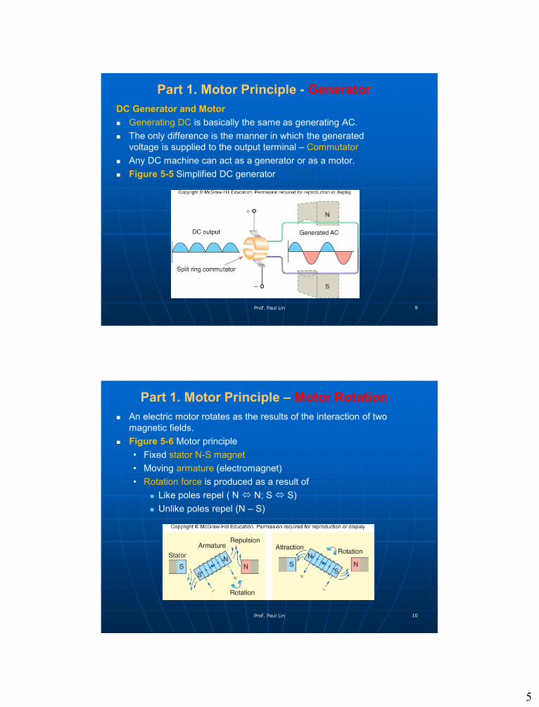
Part 1. Motor Principle - Generator
DC Generator and Motor
Generating DC is basically the same as generating AC.
The only difference is the manner in which the generated
voltage is supplied to the output terminal – Commutator
Any DC machine can act as a generator or as a motor.
Figure 5-5 Simplified DC generator
Prof. Paul Lin 9
Part 1. Motor Principle – Motor Rotation
An electric motor rotates as the results of the interaction of two
magnetic fields.
Figure 5-6 Motor principle
• Fixed stator N-S magnet
• Moving armature (electromagnet)
• Rotation force is produced as a result of
Like poles repel ( N N; S S)
Unlike poles repel (N – S)
Prof. Paul Lin 10

6
Part 1. Motor Principle – Motor Rotation
The interaction between
• Magnetic field produced by
the current Permanent N-
S field
• A force being experienced by
the conductor
Figure 5-7 A current-carrying
conductor, placed in a magnetic
field
Figure 5-8 Right-hand motor
rule
• Fixed stator N-S magnet
• Moving armature
(electromagnet)
Prof. Paul Lin 11
Part 1. Motor Principle – Motor Rotation
Developing Motor Torque
(Rotational force)
T = F*r
Figure 59 Developing motor
torque
• By a current-carrying coil or
loop of wire placed in a
magnetic field
Prof. Paul Lin 12

7
Part 2. Direct Current Motors
Figure 5-11 Typical DC industrial motor
application
For applications with high torque and
variable speed; Examples: Mine hoist,
steel rolling mills, ship propulsion,
cranes, conveyors, and elevators
Ohio Electric Motors,
http://www.ohioelectricmotors.com/dc-
motors-used-in-electric-hoists-reels-and-
winches-1597
Figure 5-12 Major components of a DC
motor
More complicated and expensive than
that of an AC motor
Major components: Commutator,
brushes, and armature windings
Cost for maintenance of the
brush/commutator assembly Prof. Paul Lin 13
Part 2. Direct Current Motors
DC Motor Parameters
Speed: Motor shaft rotational speed, in RPM
Torque:
• Turning force supplied by the motor’s shaft
• T = F * r (force acting on a radius)
• Units:
lb-in (pound-inches)
lb-ft (pound-ft)
Horsepower: the rate at which work is done.
• 1 hp ≈ lifting 33,000 pounds of object to a height of 1 foot in 1
minute
• 1 hp = 746 watts of electric power
DC Current Motors and Drives (1/50 to 3000 hp),
http://www.baldor.com/mvc/DownloadCenter/Files/BR600
Baldor Shekby Plant - DC Manufacturing Plant, 2:35 min, video,
https://www.youtube.com/watch?v=I7WXETxQm30Prof. Paul Lin 14

8
Part 2. Direct Current Motors
Permanent-Magnet DC Motors
Use permanent magnets to
supply the main field flux
and electromagnets to
provide the armature flux.
Movement of the magnetic
field of the armature is
achieved by switching current
between coils within the
motor – called commutation
Figure 5-13 Permanent-
magnet DC motor operation
Youtube Video
DC Motor, How it works,
Learn Engineering, 4:49 min
video,
https://www.youtube.com/wat
ch?v=LAtPHANEfQo Prof. Paul Lin 15
Part 2. Direct Current Motors
Permanent-Magnet DC Motors
Figure 5-14 Permanent-
magnet DC motor
Figure 5-15 Armature
commutation of switching
effect
Prof. Paul Lin 16

9
Part 2. Direct Current Motors
Permanent-Magnet DC Motors
Figure 5-16 Reversing the direction of rotation of a PM motor
Forward/Reverse Control
• Current direction through the armature
Speed control:
• Vary the voltage value apply to the armature
• Higher voltage => Higher speed
• Lower voltage => Lower speed
Prof. Paul Lin 17
Part 2. Direct Current Motors
Series DC DC Motors
Figure 5-17 Series-type DC motor
Series filed: low resistance field (Rs) and low resistance armature
(Ra)
At starting, when DC supply voltage E is applied to the motor, the
starting current is high I = E/(Rs + Ra)
High current => Strong magnetic fields inside the motor =>
produce high torque (Torque & I2)
Idea for starting very heavy mechanical loads
Prof. Paul Lin 18

10
Part 2. Direct Current Motors
Series DC Motors
Figure 5-18 Speed-torque characteristics
curves for a DC series
Speed Curve
Speed varies widely between no load
and rated load => cannot be used where
a constant speed I required
Run faster with a light load (low current);
Run slower as the load increases
Ability to start very heavy loads
Application areas: cranes, hoists and
elevators
Caution: Never operate a series motor
without a load
Prof. Paul Lin 19
Part 2. Direct Current Motors
Shunt DC Motors
Figure 5-19 Shunt-type DC motor
Shunt field (F1, F2) – higher
resistance
Armature and Shunt field –
connect in parallel
Figure 5-20 Speed-torque
characteristic for a shunt DC
motor
The current through the shunt
field wining: constant, does not
vary with the motor speed
The torque will vary only with
the current through the
armature
Prof. Paul Lin 20

11
Part 2. Direct Current Motors
Shunt DC Motors
Figure 5-21 Separately excited motor (variable speed drive)
Independent control of the field and armature
• DC controller => Armature voltage
• DC controller => Shunt field voltage
Prof. Paul Lin 21
Part 2. Direct Current Motors
Compound DC Motors
Figure 5-22 Compound-type DC
motor
Shunt field (F1, F2) – higher
resistance
Armature and Series field –
connect in series
Cumulative-compound
connection
• Under load the series field
flux and shunt field flux act
in the same direction to
strengthen the total field
flux
Prof. Paul Lin 22
12
Part 2. Direct Current Motors
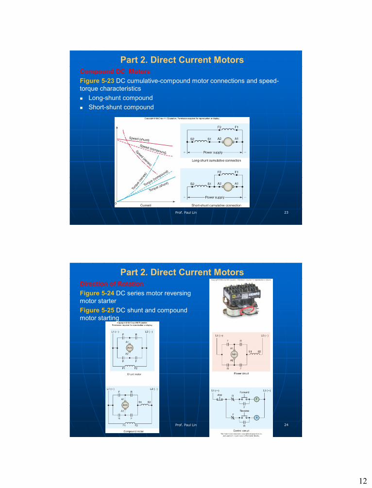
Compound DC Motors
Figure 5-23 DC cumulative-compound motor connections and speed-
torque characteristics
Long-shunt compound
Short-shunt compound
Prof. Paul Lin 23
Part 2. Direct Current Motors
Direction of Rotation
Figure 5-24 DC series motor reversing
motor starter
Figure 5-25 DC shunt and compound
motor starting
Prof. Paul Lin 24

13
Part 2. Direct Current Motors
Motor Counter Electromotive Force
(CEMF)
Figure 5-26 Motor CEMF
CEMF (back EMF) – a form of
resistance that opposes and limits
the flow of armature current
IA = (VMTR – CEMF)/RA
where
IA = armature current
VMTR = motor terminal voltage
RA = armature circuit resistance
Prof. Paul Lin 25
Part 2. Direct Current Motors
Motor Counter Electromotive Force
(CEMF)
Example 5-1 The armature of a 250V
DC motor draws 15A when operating at
full load and has a resistance of 2Ω.
Determine the counter EMF (back EMF)
produced by the armature when
operating at full load.
Solution:
IA = (VMTR – CEMF)/RA
CEMF = VMTR –( IA * RA)
= 250 V – (15 * 2) = 230V
Prof. Paul Lin 26

14
Part 2. Direct Current Motors
Speed Regulation
A measure of motor’s ability to maintain its speed from no load to full
load without a change is the applied voltage to the armature or fields
Percent speed regulation = ((No-load speed – Full-load speed)/Full-
load speed) * 100
Example 5-2 A DC shunt motor is running with a measured no-load
speed of 1775 rpm. When full load is applied, the speed drops slightly
to 1725 rpm. Find the percentage speed regulation.
Solution:
Percent speed regulation = ((1775 – 1725)/1725) * 100 = 2.9%
Prof. Paul Lin 27
Part 2. Direct Current Motors
Varying DC Motor Speed
Figure 5-29 DC motor speed
Prof. Paul Lin 28
Figure 5-30 Armature-controlled
DC motor

15
Part 2. Direct Current Motors
Varying DC Motor Speed
Figure 5-30 Armature
controlled DC motor
Prof. Paul Lin 29
Part 2. Direct Current Motors
DC Motor Drives
Figure 5-32 The block diagram for a typical
DC motor drive
Figure 5-32 Typical DC motor drive unit
Prof. Paul Lin 30
16
Summary & Conclusion
Questions?Contact Prof. Lin through:
Email: [email protected]
Prof. Paul Lin 31