ECET 211 Electric Machines & Controls Lecture 3-1...
10
1 1 ECET 211 Electric Machines & Controls Lecture 3-1 (Part 1 of 2) Motor Transformers and Distribution Systems Text Book: Electric Motors and Control Systems , by Frank D. Petruzella, published by McGraw Hill, 2015. Paul I-Hai Lin, Professor of Electrical and Computer P.E. States of Indiana & California Dept. of Computer, Electrical and Information Technology Purdue University Fort Wayne Campus Prof. Paul Lin Lecture 3 Motor Transformers and Distribution Systems Chapter 3. Motor Transformers and Distribution Systems • Part 1. Power Distribution • Part 2. Transformer Principles • Part 3. Transformer Connections and Systems Prof. Paul Lin 2
-
Upload
hoangthuan -
Category
Documents
-
view
214 -
download
0
Transcript of ECET 211 Electric Machines & Controls Lecture 3-1...
1
1
ECET 211 Electric Machines & Controls
Lecture 3-1 (Part 1 of 2)
Motor Transformers and Distribution Systems
Text Book: Electric Motors and Control Systems, by Frank D.
Petruzella, published by McGraw Hill, 2015.
Paul I-Hai Lin, Professor of Electrical and Computer
P.E. States of Indiana & California
Dept. of Computer, Electrical and Information Technology
Purdue University Fort Wayne Campus
Prof. Paul Lin
Lecture 3 Motor Transformers and Distribution
Systems Chapter 3. Motor Transformers and Distribution Systems
• Part 1. Power Distribution
• Part 2. Transformer Principles
• Part 3. Transformer Connections and Systems
Prof. Paul Lin 2
2
Lecture 3 Motor Transformers and Distribution
Systems Part 1. Power Distribution
Transformers
• Electrical apparatus that transfer electrical energy from one
electrical circuit to another by magnetic coupling
• Transfer electricity from one electric circuit to another by means
of electromagnetic mutual induction
• Roles that transformers play in motor power distribution and
control systems
• The purpose: converts AC power at voltage level to AC power of
the same frequency at another voltage level
Distribution System
• Refers to the manner in which electrical energy is transmitted
from the generators to its many point of use
Prof. Paul Lin 3
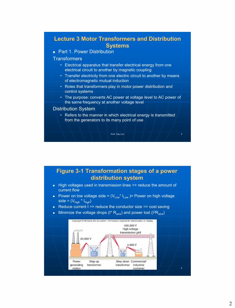
Figure 3-1 Transformation stages of a power
distribution system
High voltages used in transmission lines => reduce the amount of
current flow
Power on low voltage side = (VLow* ILow )= Power on high voltage
side = (Vhigh * Ihigh)
Reduce current I => reduce the conductor size => cost saving
Minimize the voltage drops (I* Rwire) and power lost (I2Rwire)
Prof. Paul Lin 4

3
Figure 3-2 High voltage reduces the required
amount of transmission current required
100 A vs. 1 A for efficient electrical energy distribution and
transmission
• P = V * I = 100 V * 100A = 10,000 W without transformers
• P = V* I = 10,000 V * 1A = 10,000 W with transformer
Power loss of transformer (10% to 2 or 1%)
Prof. Paul Lin 5
Lecture 3 Motor Transformers and Distribution
Systems Chapter 3. Motor Transformers and Distribution Systems
Part 1. Power Distribution
Figure 3-3 Power Grid Transformers
Prof. Paul Lin 6

4
Lecture 3 Motor Transformers and Distribution
Systems A power substation consists of equipment installed for switching,
changing or regulating line voltage
Figure 3-4 Factory assembled unit substation
Figure 3-5 Single-line diagram for a typical unit
substation: High-voltage primary switchgear,
Transformer section, Low-voltage distribution
section
Prof. Paul Lin 7
Distribution Systems
Used to distribute power throughout large commercial and industrial
facilities.
Power must be distributed through various switchgears, transformers,
and panelboards.
Figure 3-6 Typical commercial/industrial distribution systemProf. Paul Lin 8

5
Distribution Systems
Sections of a typical electrical distribution system
• Service entrance
• Feeders
• Branch circuits
Figure 3-7 Single-line diagram for a typical electrical distribution system
Prof. Paul Lin 9
Conductor Ampacity and Common Types of
Raceways Conductor Ampacity – the maximum amount of current the conductor
can safely carry without becoming over heat,
NEC Conductor size, insulation, and operating condition
• NEC Article 310: Conductors for General Wiring,
http://www.houwire.com/products/technical/article310_16.html
Types of Raceways
• Conduit
• Cable Trays
• Low-impedance Busways
(bus duct)
• Plug-in busways
Figure 3-8 Common types of raceways
Prof. Paul Lin 10
6
Power Losses
Power Losses
• Transmission loss
• Distribution loss
Common example of losses in the power gird
• Line losses (I2 *R)
• Transformer losses (no-load losses)
• Poor power factor losses
P = V*I* Cosθ – single phase load
P = √3* V*I* Cosθ = 1.732* V*I* Cosθ – three phase load
• Power factor correction apparatus/device - capacitor
Prof. Paul Lin 11
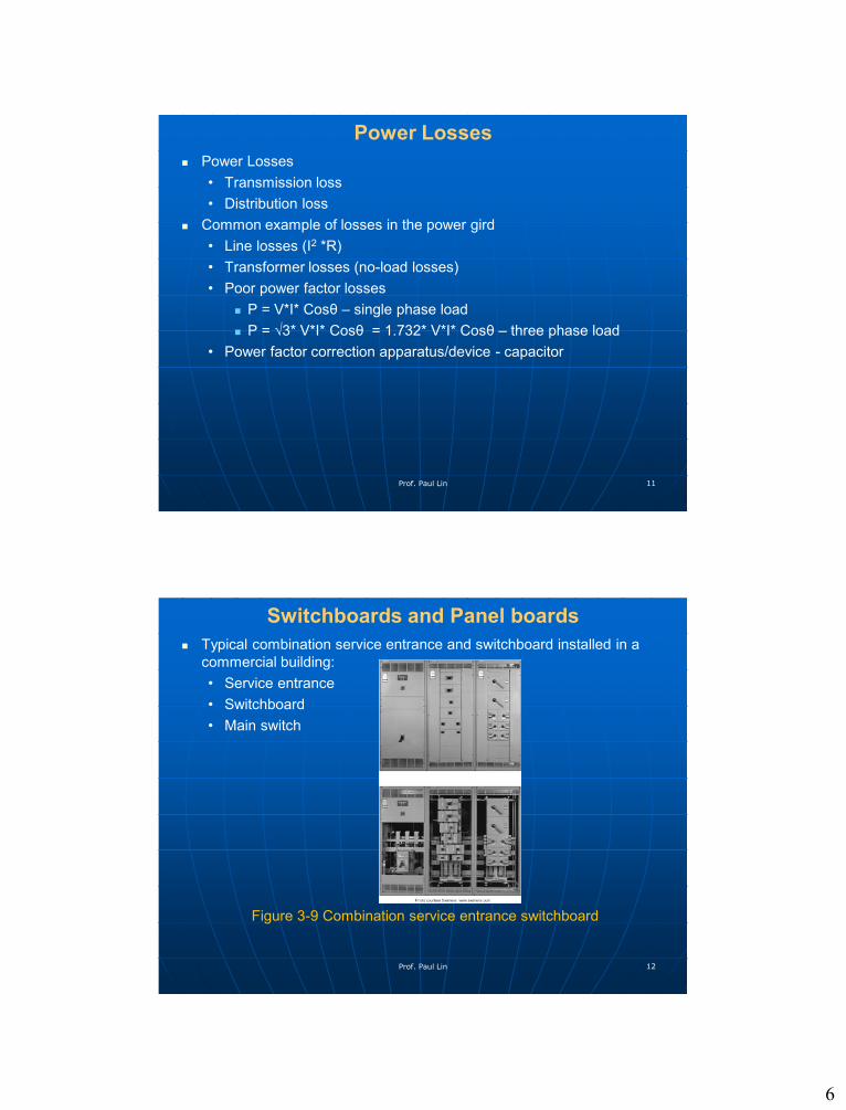
Switchboards and Panel boards
Typical combination service entrance and switchboard installed in a
commercial building:
• Service entrance
• Switchboard
• Main switch
Figure 3-9 Combination service entrance switchboard
Prof. Paul Lin 12

7
Switchboards and Panelboards A Panelboard - contains a group of circuit breaker of fuse protective
devices for lighting, convenience receptacles and power distribution
branch circuits
Figure 3-10 Typical panelboard installation
Prof. Paul Lin 13
Switchboards and Panelboards Typical internal wiring for a 277/480 V, three-phase, four-wire panel
equipped with circuit breaker.
VL (Line-to-Line voltage) = 480V
VLN (Line to neutral voltage) = 480/√3 = 480/1.732 = 277 V => for
single phase lighting load, motor load
Figure 3-11 Wiring for a 277/480V, three-phase, four-wire panelboardProf. Paul Lin 14
8
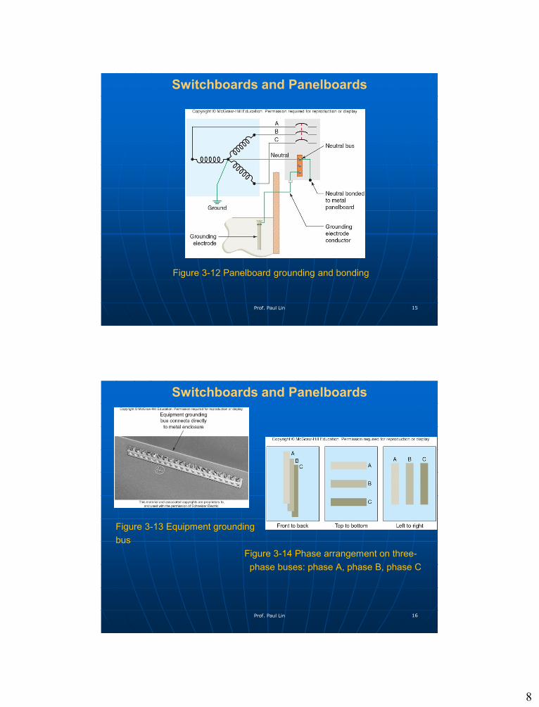
Switchboards and Panelboards
Figure 3-12 Panelboard grounding and bonding
Prof. Paul Lin 15
Switchboards and Panelboards
Figure 3-13 Equipment grounding
bus
Figure 3-14 Phase arrangement on three-
phase buses: phase A, phase B, phase C
Prof. Paul Lin 16
9
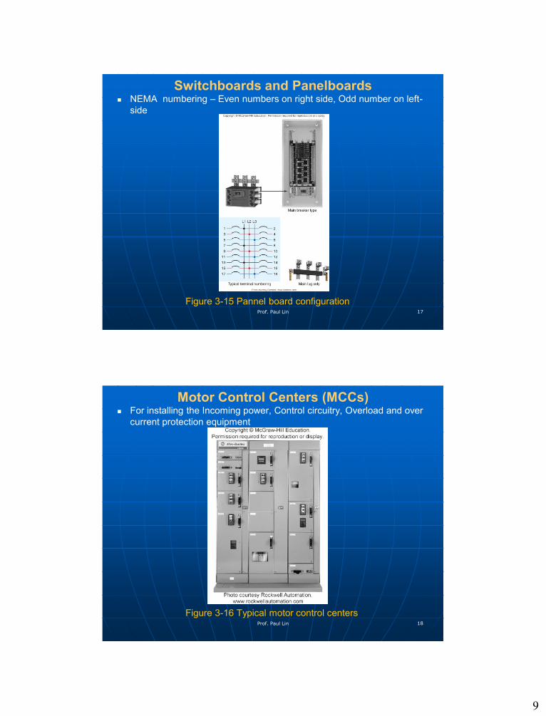
Switchboards and Panelboards NEMA numbering – Even numbers on right side, Odd number on left-
side
Figure 3-15 Pannel board configurationProf. Paul Lin 17
Motor Control Centers (MCCs) For installing the Incoming power, Control circuitry, Overload and over
current protection equipment
Figure 3-16 Typical motor control centersProf. Paul Lin 18

10
Figure 3-17 Major Components of Motor Control Centers Feeder circuit breakers, Feeder fusible disconnects, Transformers,
Metering equipment
Contactors, NEMA and IEC non-reversing and reversing full-voltage
starters, soft starters, AC variable frequency drives’, PLCs, Solid-state
motor controllers
Prof. Paul Lin 19
Summary & Conclusion
Questions?Contact Prof. Lin through:
Email: [email protected]
Prof. Paul Lin 20