ECEN720: High-Speed Links Circuits and Systems Spring...
27
Sam Palermo Analog & Mixed-Signal Center Texas A&M University ECEN720: High-Speed Links Circuits and Systems Spring 2017 Lecture 4: Channel Pulse Model & Modulation Schemes
-
Upload
duongquynh -
Category
Documents
-
view
232 -
download
4
Transcript of ECEN720: High-Speed Links Circuits and Systems Spring...

Sam PalermoAnalog & Mixed-Signal Center
Texas A&M University
ECEN720: High-Speed Links Circuits and Systems
Spring 2017
Lecture 4: Channel Pulse Model & Modulation Schemes

Announcements & Agenda
• Lab 1 Report and Prelab 2 due Feb. 6
• ISI• Channel pulse model• Peak distortion analysis• Compare NRZ, PAM-4, and Duobinary modulation• Reference material for this lecture
• Peak distortion analysis paper by Casper (posted on web)
• Notes from H. Song, Arizona State• Papers posted on PAM-4 and duobinary modulation
2
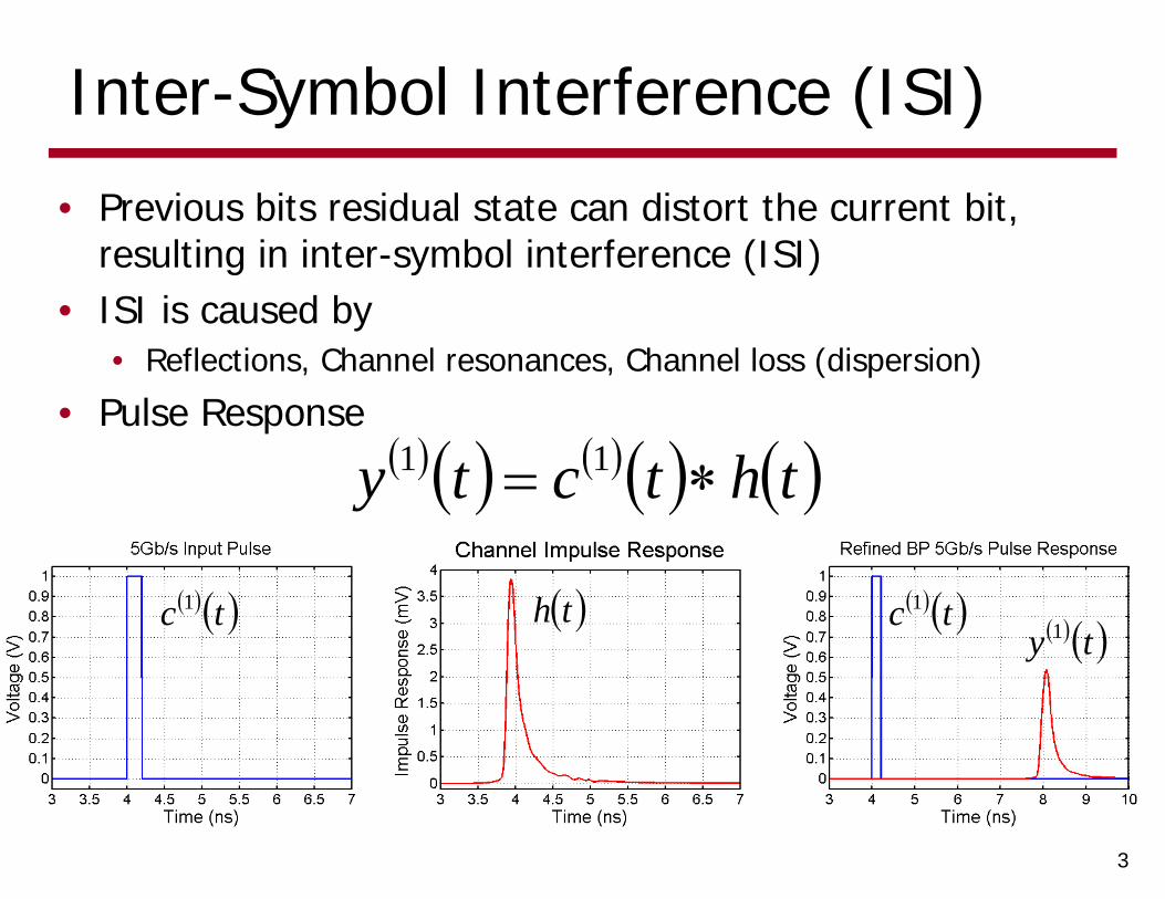
Inter-Symbol Interference (ISI)
• Previous bits residual state can distort the current bit, resulting in inter-symbol interference (ISI)
• ISI is caused by• Reflections, Channel resonances, Channel loss (dispersion)
• Pulse Response
3
tc 1 th tc 1 ty 1
thtcty 11
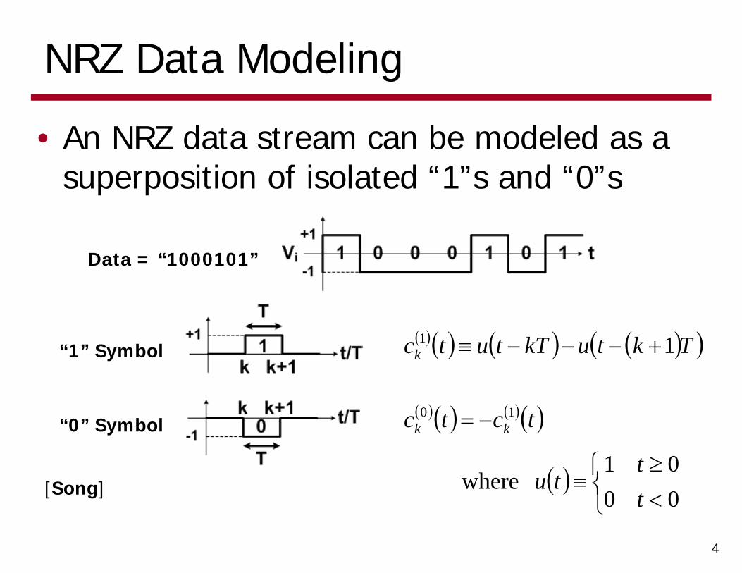
NRZ Data Modeling
• An NRZ data stream can be modeled as a superposition of isolated “1”s and “0”s
4
Data = “1000101”
“1” Symbol
“0” Symbol
TktukTtutck 11
tctc kk10
0001
wherett
tu[Song]
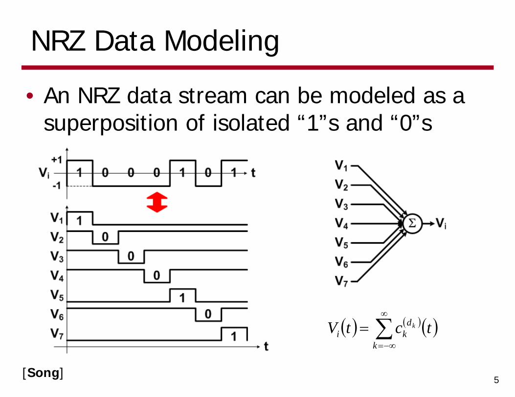
NRZ Data Modeling
• An NRZ data stream can be modeled as a superposition of isolated “1”s and “0”s
5
k
dki tctV k
[Song]
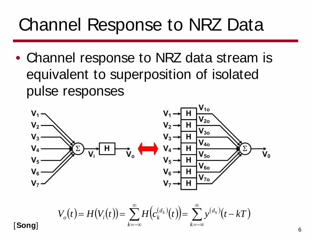
Channel Response to NRZ Data
• Channel response to NRZ data stream is equivalent to superposition of isolated pulse responses
6
k
d
k
dkio kTtytcHtVHtV kk
[Song]
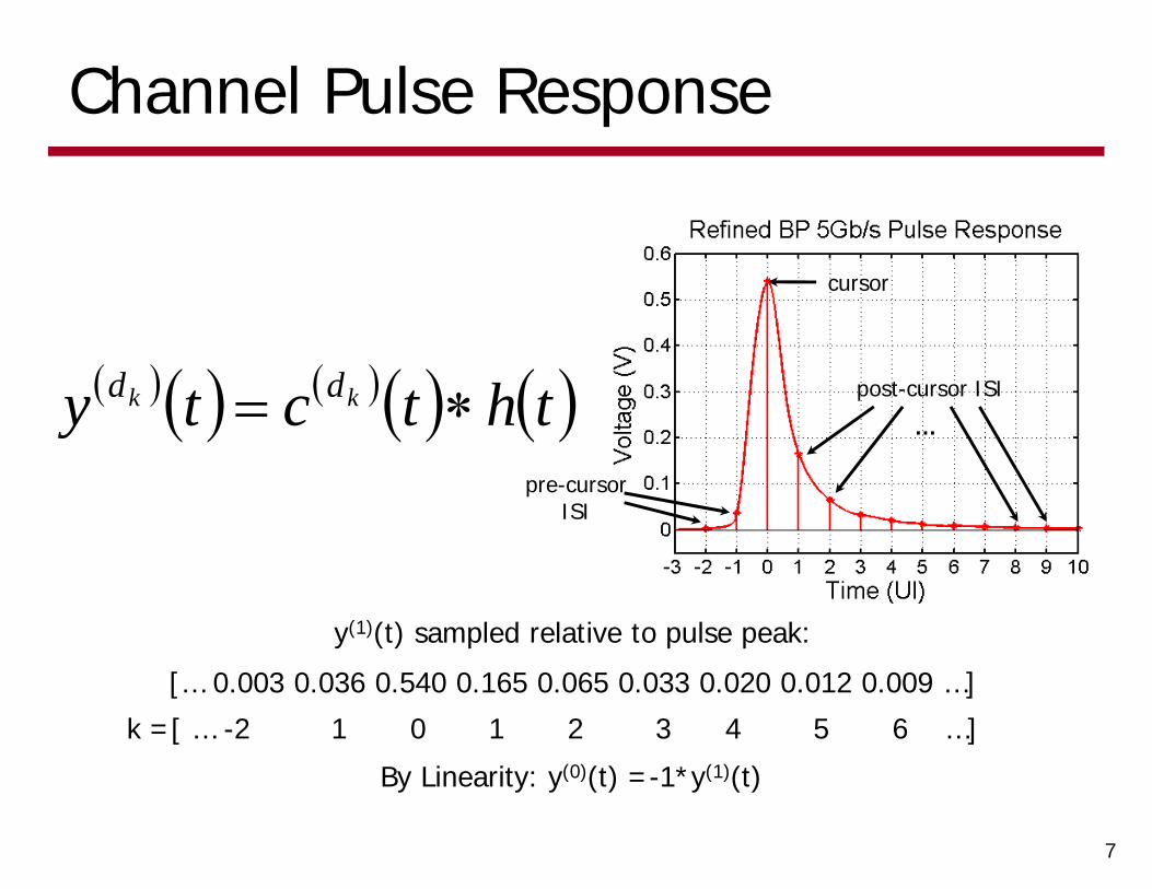
Channel Pulse Response
7
thtcty kk dd
y(1)(t) sampled relative to pulse peak:
[… 0.003 0.036 0.540 0.165 0.065 0.033 0.020 0.012 0.009 …]
k =[ … -2 1 0 1 2 3 4 5 6 …]
By Linearity: y(0)(t) =-1*y(1)(t)
cursor
post-cursor ISI
pre-cursor ISI
…
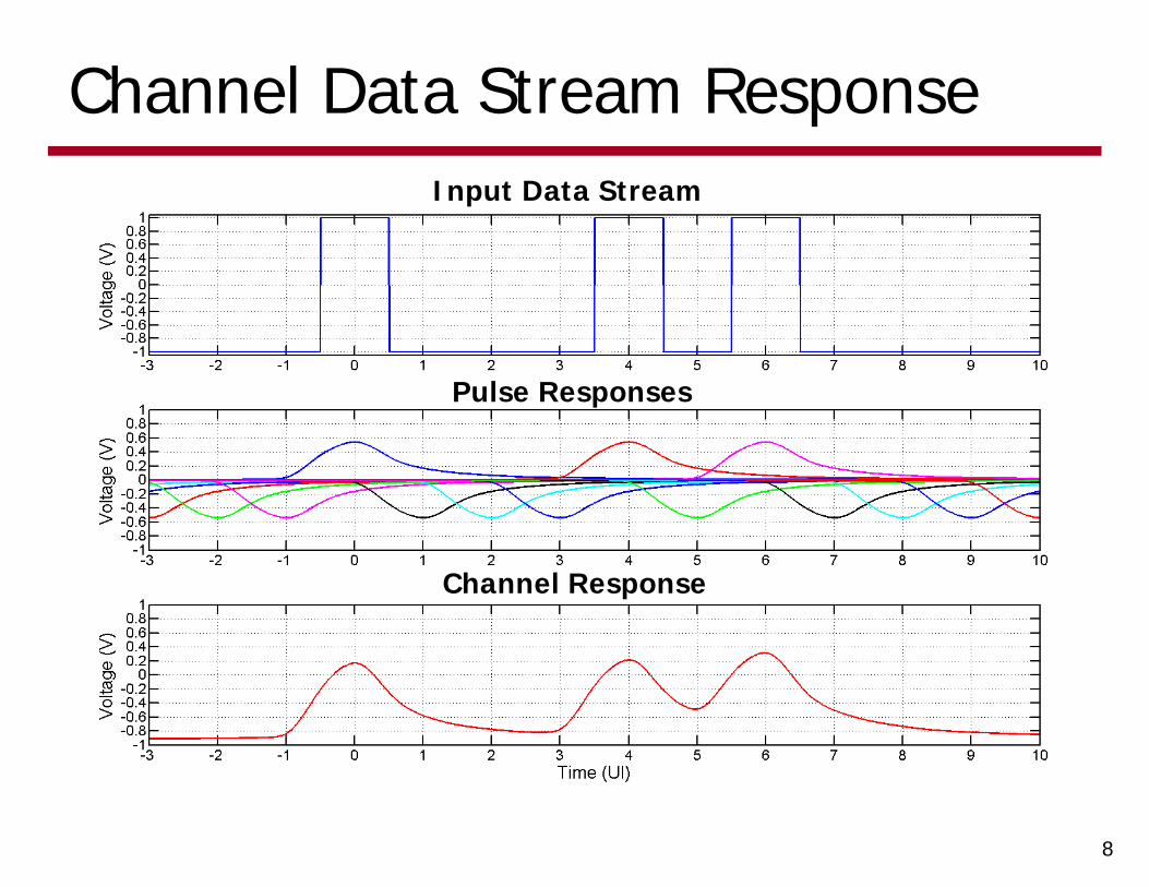
Channel Data Stream Response
8
Input Data Stream
Pulse Responses
Channel Response
a-1
a0
a1
a2 a3
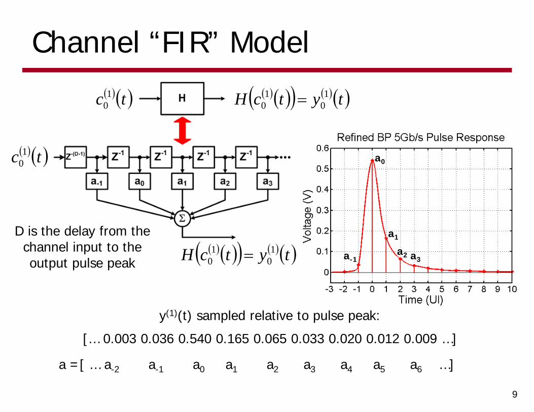
Channel “FIR” Model
9
tc 10
tc 10
tytcH 10
10
tytcH 10
10
y(1)(t) sampled relative to pulse peak:
[… 0.003 0.036 0.540 0.165 0.065 0.033 0.020 0.012 0.009 …]
a =[ … a-2 a-1 a0 a1 a2 a3 a4 a5 a6 …]
D is the delay from the channel input to the output pulse peak
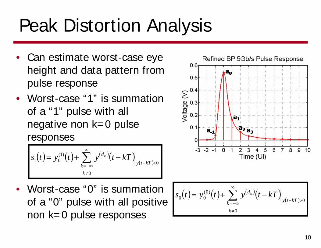
Peak Distortion Analysis
• Can estimate worst-case eye height and data pattern from pulse response
• Worst-case “1” is summation of a “1” pulse with all negative non k=0 pulse responses
10
0
0
)1(01
kk kTty
d kTtytyts k
• Worst-case “0” is summation of a “0” pulse with all positive non k=0 pulse responses
0
0
)0(00
kk kTty
d kTtytyts k
Peak Distortion Analysis
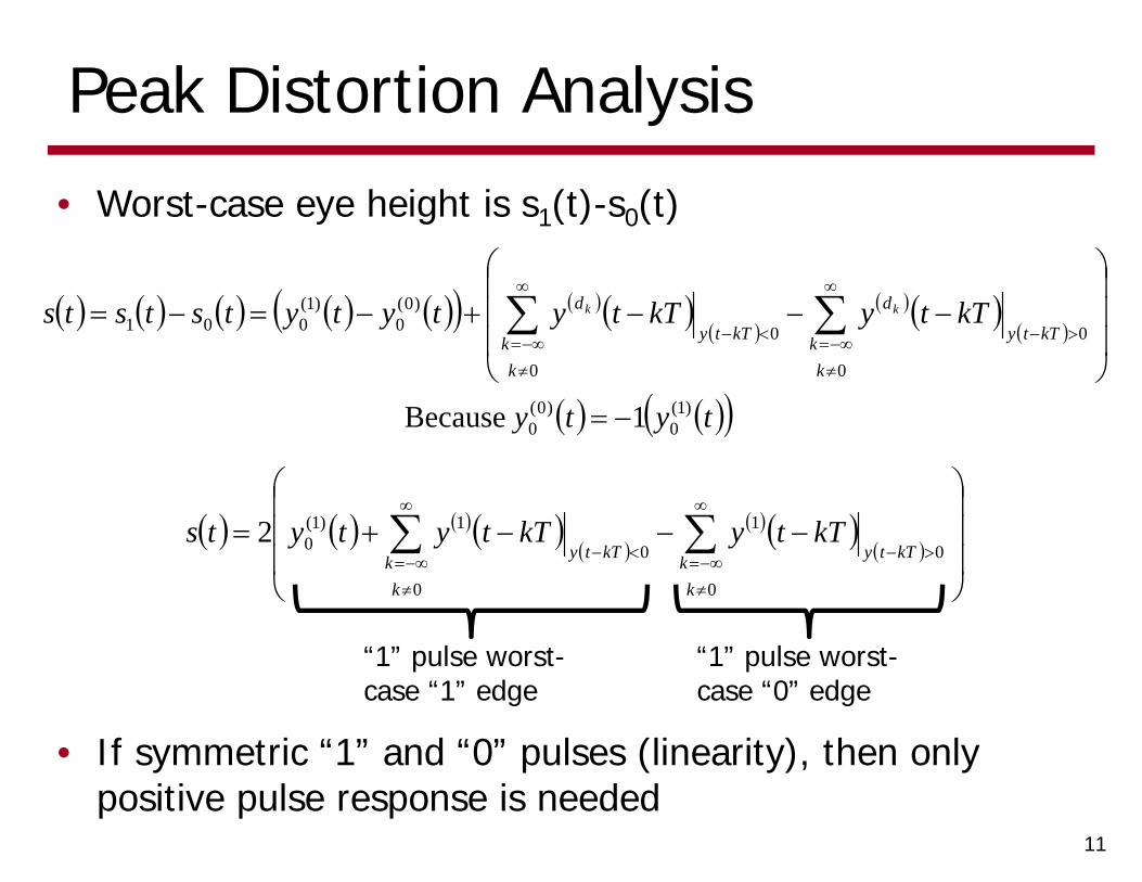
• Worst-case eye height is s1(t)-s0(t)
11
0
0
0
0
)0(0
)1(001
kk kTty
d
kk kTty
d kTtykTtytytytststs kk
• If symmetric “1” and “0” pulses (linearity), then only positive pulse response is needed
0
0
1
0
0
1)1(02
kk kTty
kk kTty
kTtykTtytyts
tyty )1(0
)0(0 1 Because
“1” pulse worst-case “1” edge
“1” pulse worst-case “0” edge
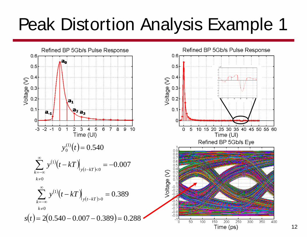
Peak Distortion Analysis Example 1
12
288.0389.0007.0540.02
389.0
007.0
540.0
0
0
1
0
0
1
)1(0
ts
kTty
kTty
ty
kk kTty
kk kTty
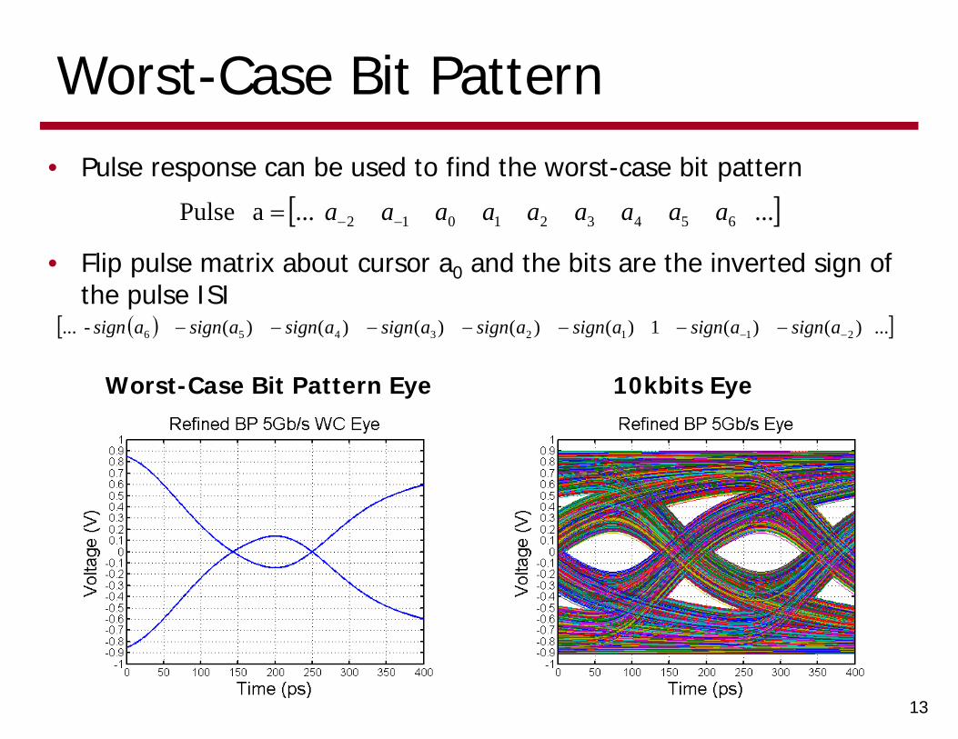
Worst-Case Bit Pattern• Pulse response can be used to find the worst-case bit pattern
13
... ...a Pulse 654321012 aaaaaaaaa
... )()(1)()()()()(- ... 21123456 asignasignasignasignasignasignasignasign
• Flip pulse matrix about cursor a0 and the bits are the inverted sign of the pulse ISI
Worst-Case Bit Pattern Eye 10kbits Eye
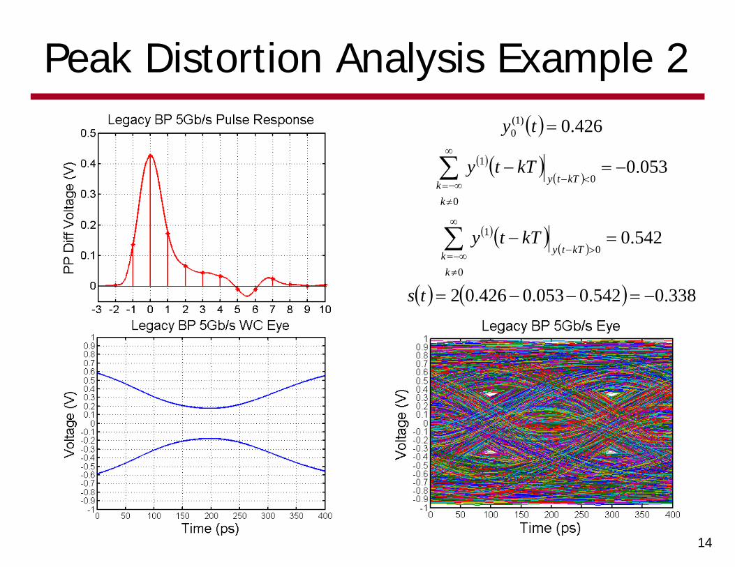
Peak Distortion Analysis Example 2
14
338.0542.0053.0426.02
542.0
053.0
426.0
0
0
1
0
0
1
)1(0
ts
kTty
kTty
ty
kk kTty
kk kTty
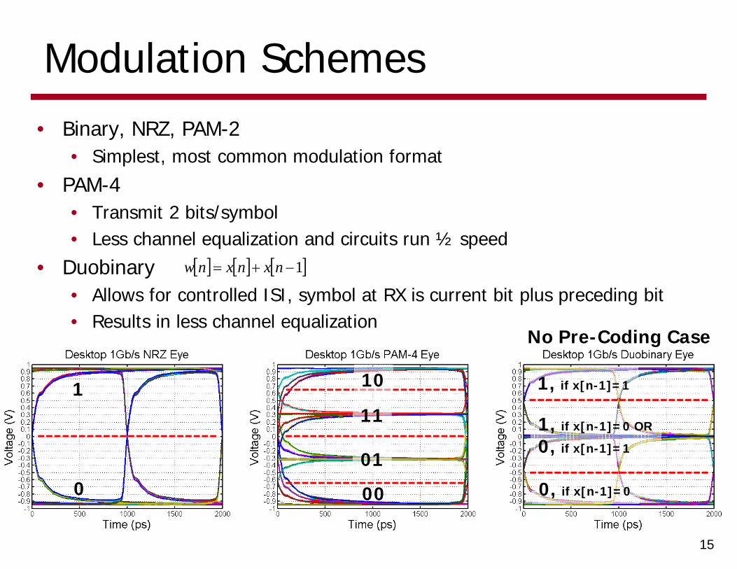
Modulation Schemes
15
• Binary, NRZ, PAM-2• Simplest, most common modulation format
• PAM-4• Transmit 2 bits/symbol• Less channel equalization and circuits run ½ speed
• Duobinary• Allows for controlled ISI, symbol at RX is current bit plus preceding bit• Results in less channel equalization
1 nxnxnw
0
1
00
01
11
10
0, if x[n-1]=0
1, if x[n-1]=0 OR
0, if x[n-1]=1
1, if x[n-1]=1
No Pre-Coding Case
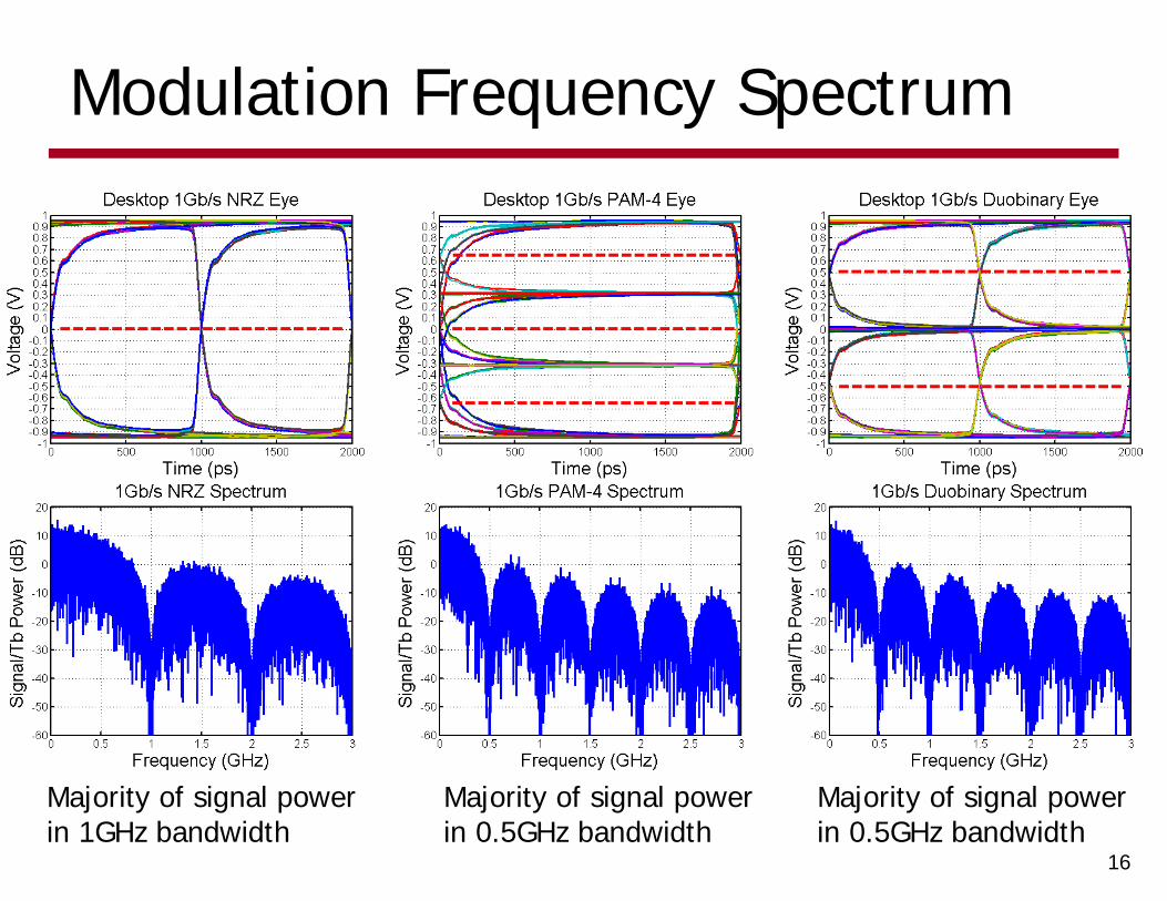
Modulation Frequency Spectrum
16
Majority of signal power in 1GHz bandwidth
Majority of signal power in 0.5GHz bandwidth
Majority of signal power in 0.5GHz bandwidth
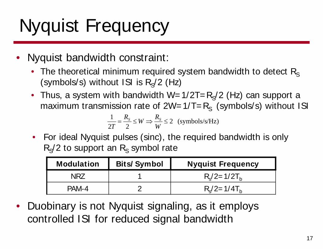
Nyquist Frequency
• Nyquist bandwidth constraint:• The theoretical minimum required system bandwidth to detect RS
(symbols/s) without ISI is RS/2 (Hz)• Thus, a system with bandwidth W=1/2T=RS/2 (Hz) can support a
maximum transmission rate of 2W=1/T=RS (symbols/s) without ISI
17
/Hz)(symbols/s 222
1
WRWR
TSS
• For ideal Nyquist pulses (sinc), the required bandwidth is only RS/2 to support an RS symbol rate
Modulation Bits/Symbol Nyquist Frequency
NRZ 1 Rs/2=1/2Tb
PAM-4 2 Rs/2=1/4Tb
• Duobinary is not Nyquist signaling, as it employs controlled ISI for reduced signal bandwidth
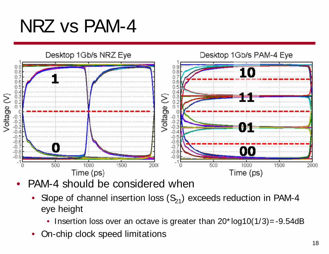
NRZ vs PAM-4
• PAM-4 should be considered when• Slope of channel insertion loss (S21) exceeds reduction in PAM-4
eye height• Insertion loss over an octave is greater than 20*log10(1/3)=-9.54dB
• On-chip clock speed limitations18
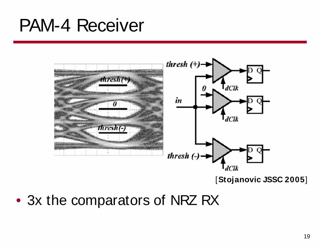
PAM-4 Receiver
• 3x the comparators of NRZ RX
19
[Stojanovic JSSC 2005]
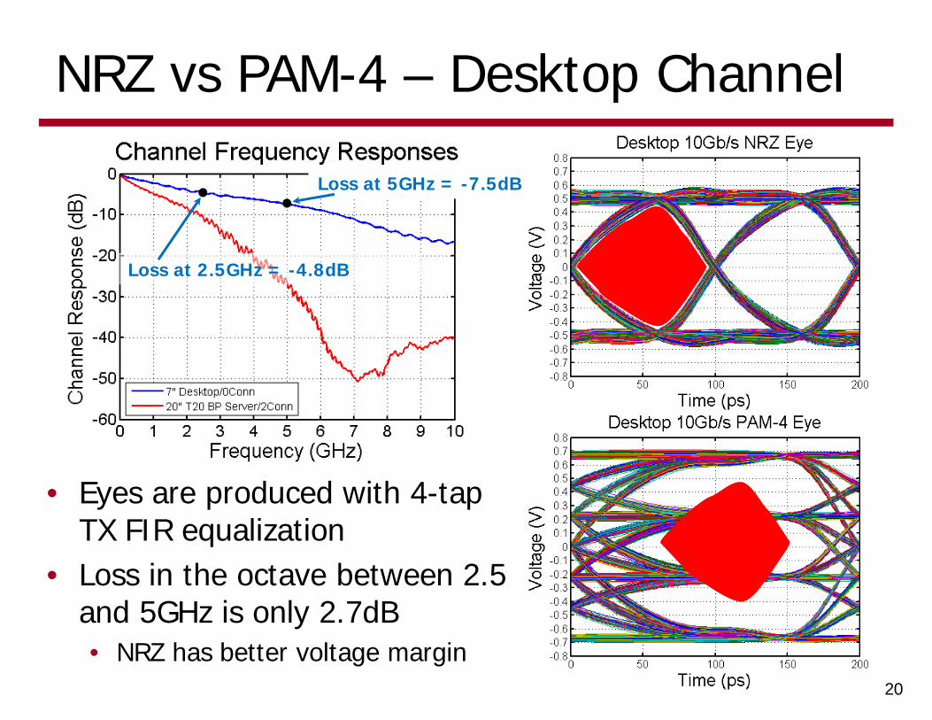
NRZ vs PAM-4 – Desktop Channel
• Eyes are produced with 4-tap TX FIR equalization
• Loss in the octave between 2.5 and 5GHz is only 2.7dB• NRZ has better voltage margin
20
Loss at 2.5GHz = -4.8dB
Loss at 5GHz = -7.5dB

NRZ vs PAM-4 – T20 Server Channel
• Eyes are produced with 4-tap TX FIR equalization
• Loss in the octave between 2.5 and 5GHz is 15.8dB• PAM-4 “might” be a better choice
21
Loss at 2.5GHz = -11.1dB
Loss at 5GHz = -26.9dB
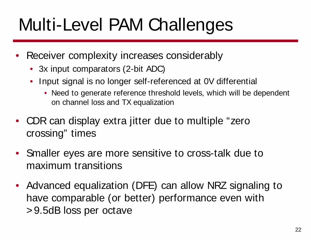
Multi-Level PAM Challenges
• Receiver complexity increases considerably• 3x input comparators (2-bit ADC)• Input signal is no longer self-referenced at 0V differential
• Need to generate reference threshold levels, which will be dependent on channel loss and TX equalization
• CDR can display extra jitter due to multiple “zero crossing” times
• Smaller eyes are more sensitive to cross-talk due to maximum transitions
• Advanced equalization (DFE) can allow NRZ signaling to have comparable (or better) performance even with >9.5dB loss per octave
22
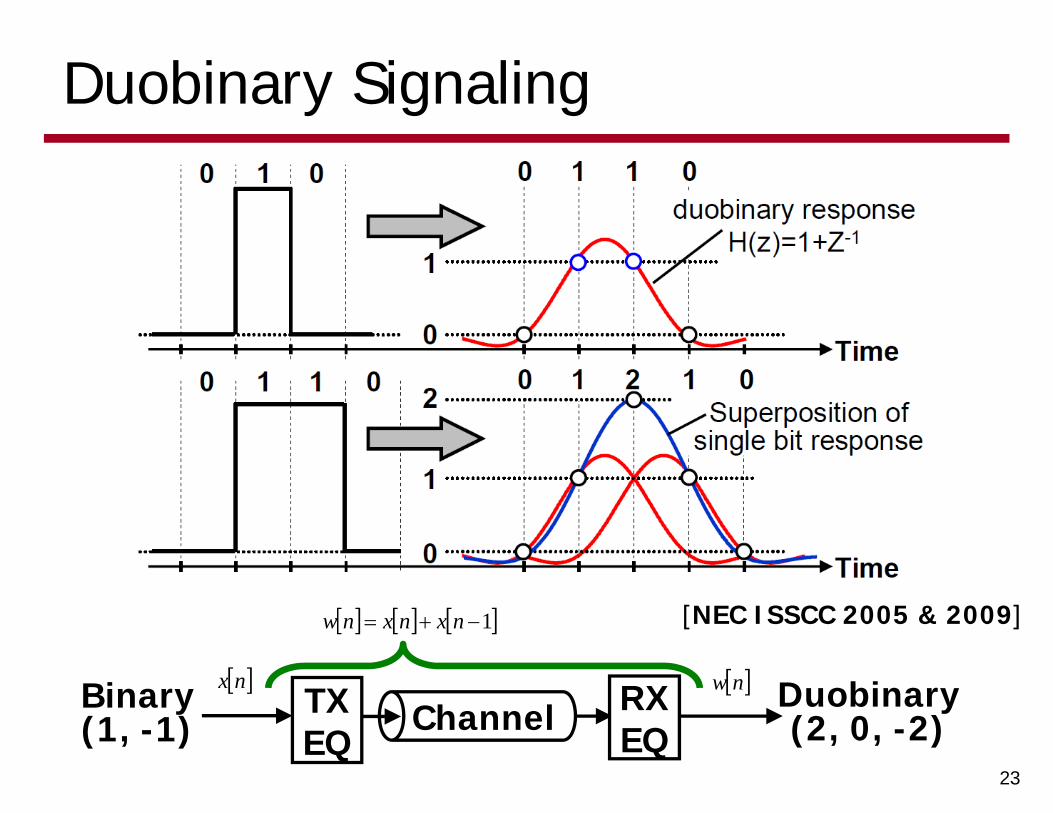
Duobinary Signaling
23
[NEC ISSCC 2005 & 2009]
Binary(1, -1)
Duobinary(2, 0, -2)ChannelTX
EQRXEQ
1 nxnxnw
nw nx
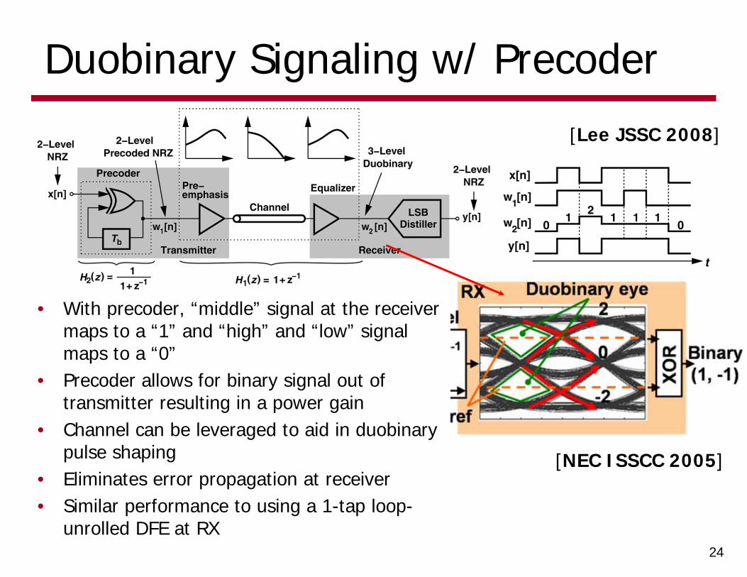
Duobinary Signaling w/ Precoder
24
[Lee JSSC 2008]
• With precoder, “middle” signal at the receiver maps to a “1” and “high” and “low” signal maps to a “0”
• Precoder allows for binary signal out of transmitter resulting in a power gain
• Channel can be leveraged to aid in duobinarypulse shaping
• Eliminates error propagation at receiver• Similar performance to using a 1-tap loop-
unrolled DFE at RX
[NEC ISSCC 2005]
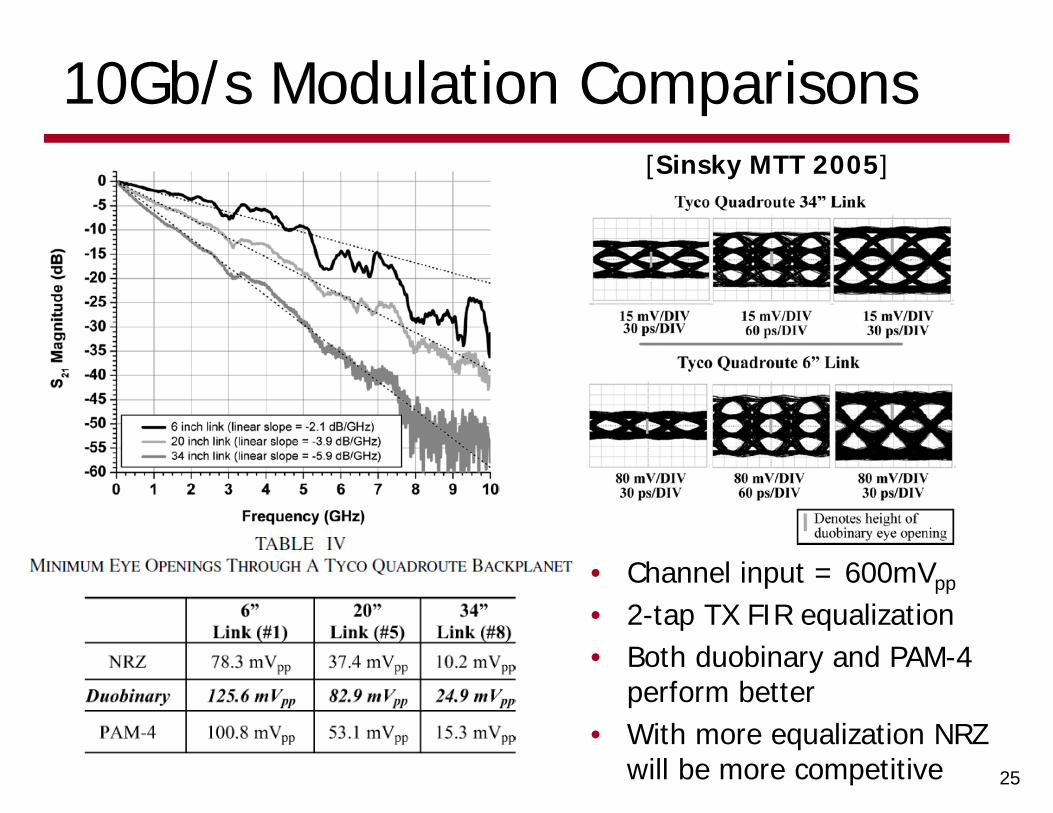
10Gb/s Modulation Comparisons
25
[Sinsky MTT 2005]
• Channel input = 600mVpp
• 2-tap TX FIR equalization• Both duobinary and PAM-4
perform better• With more equalization NRZ
will be more competitive
Modulation Take-Away Points
• Loss-slope guidelines are a good place to start in consideration of alternate modulation schemes
• More advanced modulation trades-off receiver complexity versus equalization complexity
• Advanced modulation challenges• Peak TX power limitations• Setting RX comparator thresholds and controlling offsets• CDR complexity• Crosstalk sensitivity (PAM-4)
• Need link analysis tools that consider voltage, timing, and crosstalk noise to choose best modulation scheme for a given channel
26
Next Time
• Link Circuits• Termination structures• Drivers• Receivers
27