ECE537/9 #1Fall 2009 © 2000-2009, Richard A. Stanley ECE537 Advanced and High Performance Networks...
116
ECE537/9 #1 Fall 2009 © 2000-2009, Richard A. Stanley ECE537 Advanced and High Performance Networks 9: Integrated and Differentiated Services, QoS Protocols Professor Richard A. Stanley, P.E.
-
date post
21-Dec-2015 -
Category
Documents
-
view
216 -
download
3
Transcript of ECE537/9 #1Fall 2009 © 2000-2009, Richard A. Stanley ECE537 Advanced and High Performance Networks...
ECE537/9 #1Fall 2009© 2000-2009, Richard A. Stanley
ECE537 Advanced and High Performance Networks
9: Integrated and Differentiated Services, QoS Protocols
Professor Richard A. Stanley, P.E.
ECE537/9 #2
Overview of Tonight’s Class
• Student presentations/discussions
• Review of last time
• Overview of integrated and differentiated Services, QoS protocols
ECE537/9 #3
Last time
• There are many networking protocols other than IP, and each is suited to one or more particular needs
• Because of the proliferation of IP at the desktop, viable networking protocols must support encapsulation of virtually any sort of end protocol
• Efficiency is important
ECE537/9 #4
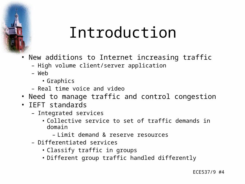
Introduction
• New additions to Internet increasing traffic– High volume client/server application– Web
• Graphics– Real time voice and video
• Need to manage traffic and control congestion• IEFT standards
– Integrated services• Collective service to set of traffic demands in domain
– Limit demand & reserve resources– Differentiated services
• Classify traffic in groups• Different group traffic handled differently
ECE537/9 #5
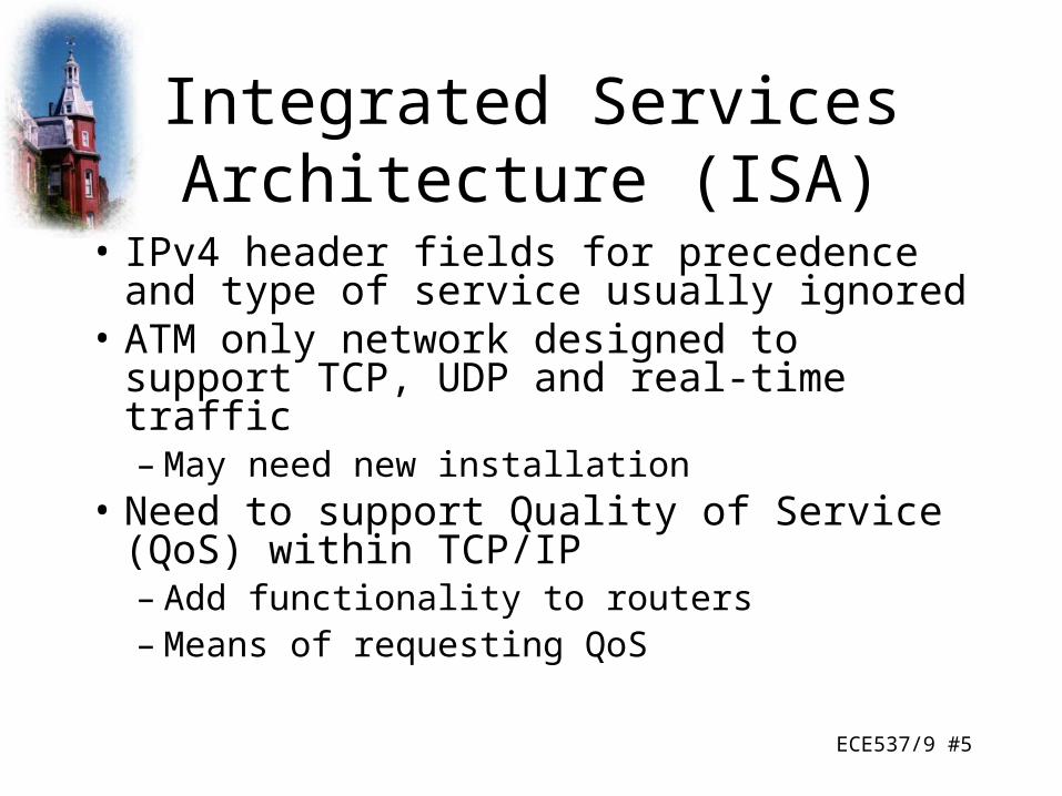
Integrated Services Architecture (ISA)
• IPv4 header fields for precedence and type of service usually ignored
• ATM only network designed to support TCP, UDP and real-time traffic– May need new installation
• Need to support Quality of Service (QoS) within TCP/IP– Add functionality to routers– Means of requesting QoS
ECE537/9 #6
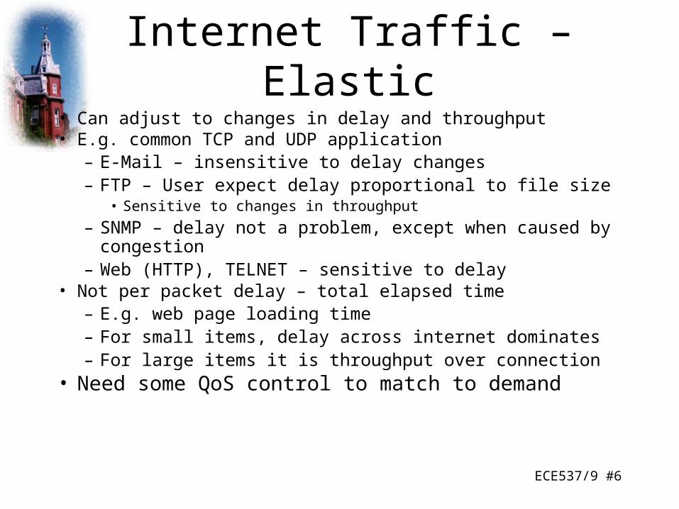
Internet Traffic – Elastic• Can adjust to changes in delay and throughput• E.g. common TCP and UDP application
– E-Mail – insensitive to delay changes– FTP – User expect delay proportional to file size
• Sensitive to changes in throughput
– SNMP – delay not a problem, except when caused by congestion– Web (HTTP), TELNET – sensitive to delay
• Not per packet delay – total elapsed time– E.g. web page loading time– For small items, delay across internet dominates – For large items it is throughput over connection
• Need some QoS control to match to demand

ECE537/9 #7
Internet Traffic – Inelastic
• Does not easily adapt to changes in delay and throughput– Real time traffic
• Throughput– Minimum may be required
• Delay– E.g. stock trading
• Jitter - Delay variation– More jitter requires a bigger buffer– E.g. teleconferencing requires reasonable upper bound
• Packet loss

ECE537/9 #8
Inelastic Traffic Problems
• Difficult to meet requirements on network with variable queuing delays and congestion
• Need preferential treatment • Applications need to state requirements
– Ahead of time (preferably) or on the fly– Using fields in IP header– Resource reservation protocol
• Must still support elastic traffic– Deny service requests that leave too few resources to
handle elastic traffic demands
ECE537/9 #9
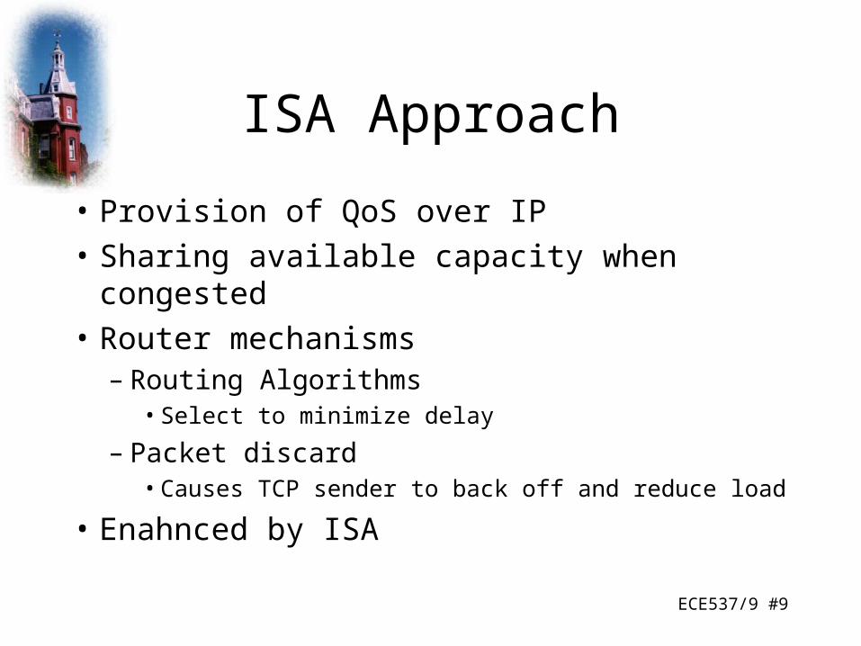
ISA Approach
• Provision of QoS over IP
• Sharing available capacity when congested
• Router mechanisms– Routing Algorithms
• Select to minimize delay
– Packet discard• Causes TCP sender to back off and reduce load
• Enahnced by ISA

ECE537/9 #10
Flow
• IP packet can be associated with a flow– Distinguishable stream of related IP packets– From single user activity– Requiring same QoS– E.g. one transport connection or one video stream– Unidirectional– Can be more than one recipient
• Multicast– Membership of flow identified by source and destination IP
address, port numbers, protocol type– IPv6 header flow identifier can be used but isnot necessarily
equivalent to ISA flow
ECE537/9 #11
ISA Functions
• Admission control– For QoS, reservation required for new flow– RSVP used
• Routing algorithm– Base decision on QoS parameters
• Queuing discipline– Take account of different flow requirements
• Discard policy– Manage congestion– Meet QoS

ECE537/9 #12
ISA Implementation in Router
• Background Functions
• Forwarding functions

ECE537/9 #13
ISA Components – Background Functions
• Reservation Protocol– RSVP
• Admission control
• Management agent– Can use agent to modify traffic control database
and direct admission control
• Routing protocol
ECE537/9 #14
ISA Components – Forwarding
• Classifier and route selection– Incoming packets mapped to classes
• Single flow or set of flows with same QoS– E.g. all video flows
• Based on IP header fields
– Determines next hop• Packet scheduler
– Manages one or more queues for each output– Order queued packets sent
• Based on class, traffic control database, current and past activity on outgoing port
– Policing
ECE537/9 #15
ISA Services
• Traffic specification (TSpec) defined as service for flow
• On two levels– General categories of service
• Guaranteed• Controlled load• Best effort (default)
– Particular flow within category• TSpec is part of contract
ECE537/9 #16
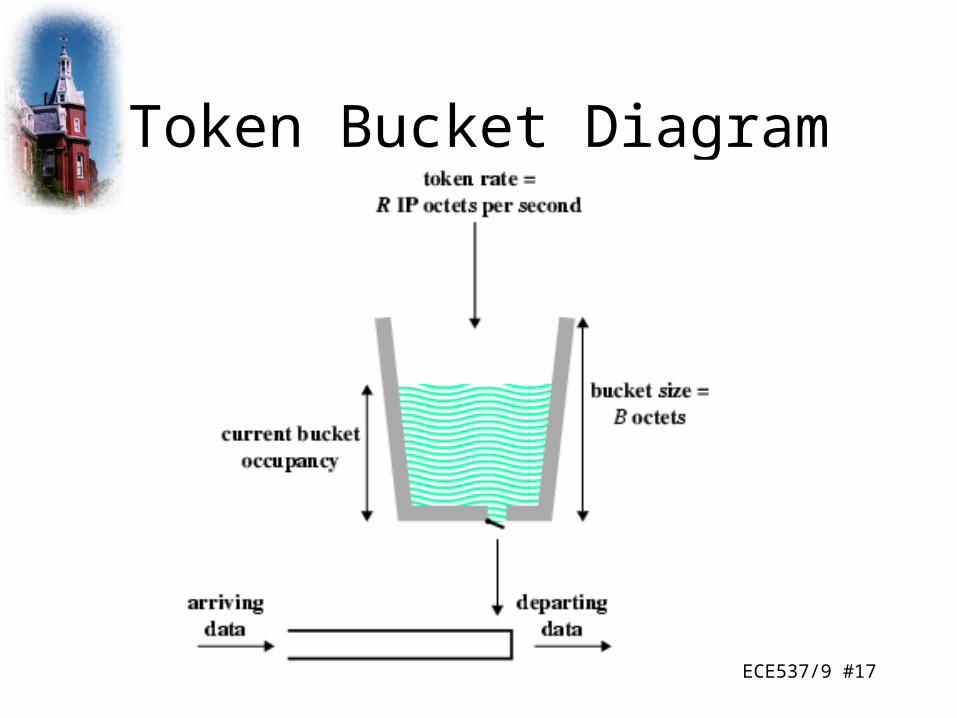
Token Bucket
• Many traffic sources can be defined by token bucket scheme
• Provides concise description of load imposed by flow– Easy to determine resource requirements
• Provides input parameters to policing function
ECE537/9 #17
Token Bucket Diagram

ECE537/9 #18
ISA Services –Guaranteed Service
• Assured capacity level or data rate• Specific upper bound on queuing delay through
network– Must be added to propagation delay or latency to get
total delay– Set high to accommodate rare long queue delays
• No queuing losses– I.e. no buffer overflow
• E.g. Real time play back of incoming signal can use delay buffer for incoming signal but will not tolerate packet loss

ECE537/9 #19
ISA Services – Controlled Load
• Tightly approximates to best efforts under unloaded conditions
• No upper bound on queuing delay– High percentage of packets do not experience delay over minimum
transit delay• Propagation plus router processing with no queuing delay
• Very high percentage delivered– Almost no queuing loss
• Adaptive real time applications– Receiver measures jitter and sets playback point– Video can drop a frame or delay output slightly– Voice can adjust silence periods
ECE537/9 #20
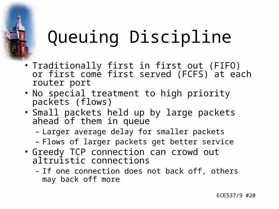
Queuing Discipline
• Traditionally first in first out (FIFO) or first come first served (FCFS) at each router port
• No special treatment to high priority packets (flows)• Small packets held up by large packets ahead of
them in queue– Larger average delay for smaller packets– Flows of larger packets get better service
• Greedy TCP connection can crowd out altruistic connections– If one connection does not back off, others may back off
more
ECE537/9 #21
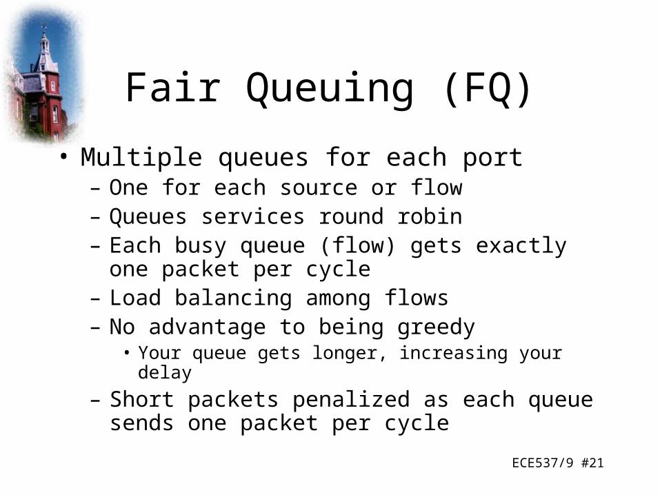
Fair Queuing (FQ)
• Multiple queues for each port– One for each source or flow– Queues services round robin– Each busy queue (flow) gets exactly one packet per
cycle– Load balancing among flows– No advantage to being greedy
• Your queue gets longer, increasing your delay
– Short packets penalized as each queue sends one packet per cycle

ECE537/9 #22
FIFO and FQ
ECE537/9 #23
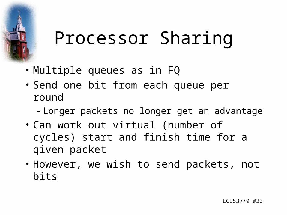
Processor Sharing
• Multiple queues as in FQ
• Send one bit from each queue per round– Longer packets no longer get an advantage
• Can work out virtual (number of cycles) start and finish time for a given packet
• However, we wish to send packets, not bits
ECE537/9 #24
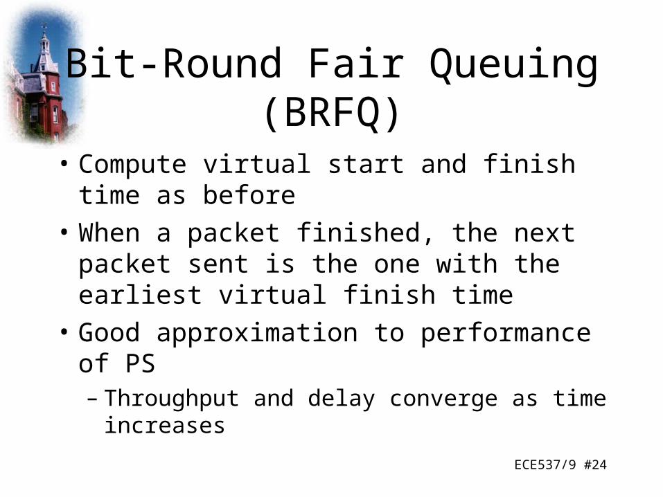
Bit-Round Fair Queuing (BRFQ)
• Compute virtual start and finish time as before
• When a packet finished, the next packet sent is the one with the earliest virtual finish time
• Good approximation to performance of PS– Throughput and delay converge as time
increases

ECE537/9 #25
Comparisonof FIFO, FQ and BRFQ

ECE537/9 #26
Generalized Processor Sharing (GPS)
• BRFQ can not provide different capacities to different flows
• Enhancement called Weighted fair queue (WFQ)• From PS, allocate weighting to each flow that
determines how many bots are sent during each round– If weighted 5, then 5 bits are sent per round
• Gives means of responding to different service requests
• Guarantees that delays do not exceed bounds
ECE537/9 #27
Weighted Fair Queue
• Emulates bit by bit GPS
• Same strategy as BRFQ

ECE537/9 #28
FIFO vs. WFQ
ECE537/9 #29
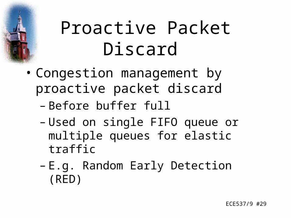
Proactive Packet Discard
• Congestion management by proactive packet discard– Before buffer full– Used on single FIFO queue or multiple queues
for elastic traffic– E.g. Random Early Detection (RED)
ECE537/9 #30
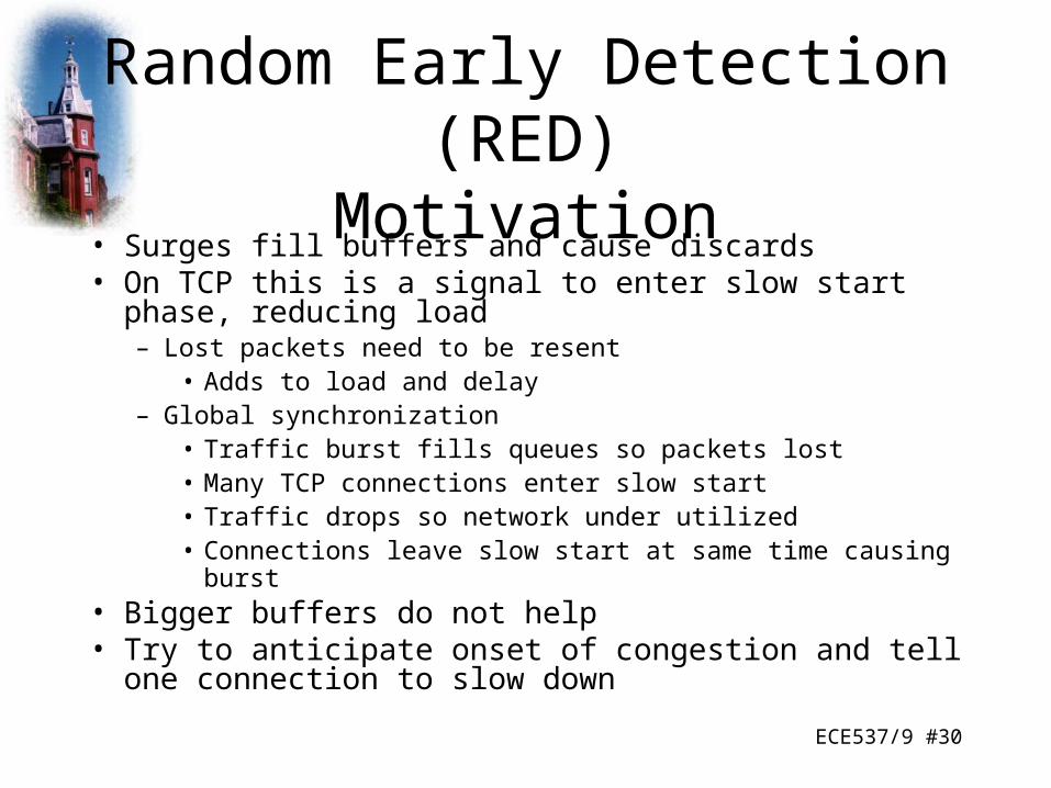
Random Early Detection (RED)Motivation
• Surges fill buffers and cause discards• On TCP this is a signal to enter slow start phase, reducing
load– Lost packets need to be resent
• Adds to load and delay– Global synchronization
• Traffic burst fills queues so packets lost• Many TCP connections enter slow start• Traffic drops so network under utilized• Connections leave slow start at same time causing burst
• Bigger buffers do not help• Try to anticipate onset of congestion and tell one connection
to slow down
ECE537/9 #31
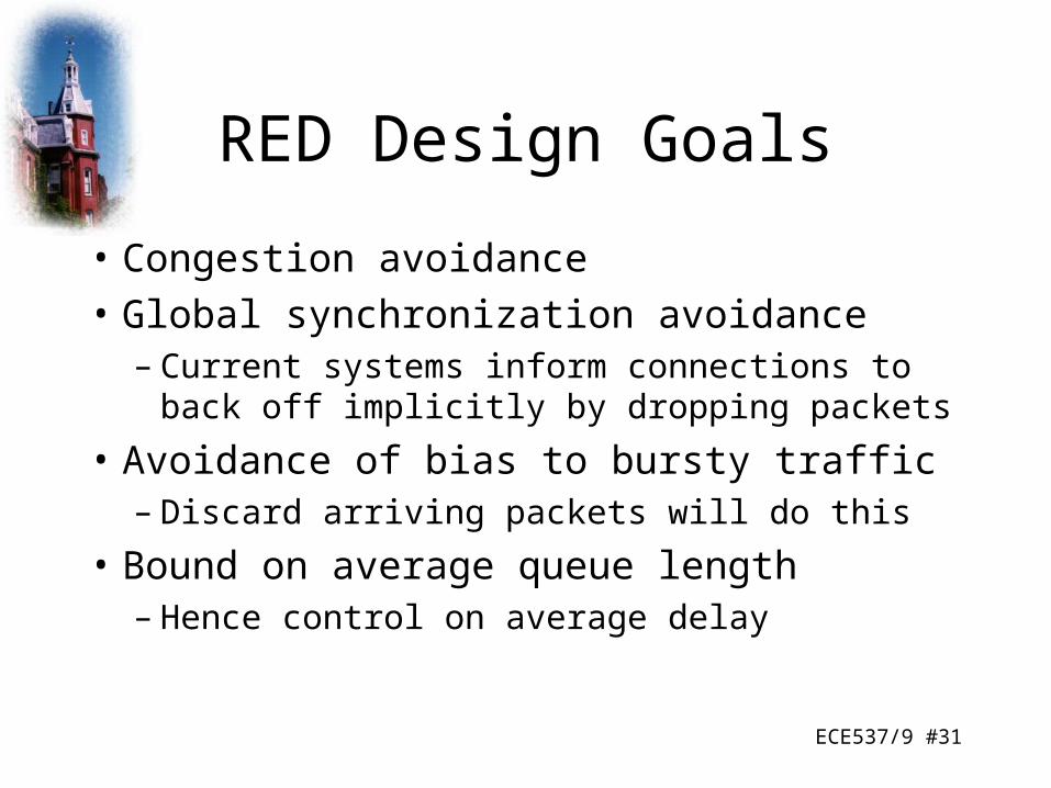
RED Design Goals
• Congestion avoidance
• Global synchronization avoidance– Current systems inform connections to back off
implicitly by dropping packets
• Avoidance of bias to bursty traffic– Discard arriving packets will do this
• Bound on average queue length– Hence control on average delay
ECE537/9 #32
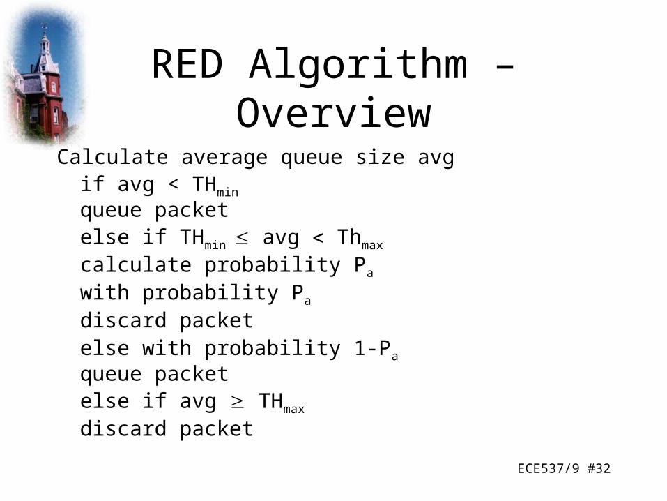
RED Algorithm – Overview
Calculate average queue size avgif avg < THmin
queue packetelse if THmin avg Thmax
calculate probability Pa
with probability Pa
discard packetelse with probability 1-Pa
queue packetelse if avg THmax
discard packet

ECE537/9 #33
RED Buffer
ECE537/9 #34
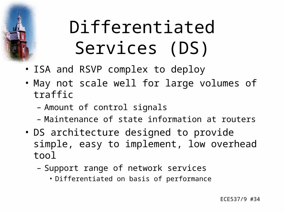
Differentiated Services (DS)
• ISA and RSVP complex to deploy• May not scale well for large volumes of traffic
– Amount of control signals
– Maintenance of state information at routers
• DS architecture designed to provide simple, easy to implement, low overhead tool– Support range of network services
• Differentiated on basis of performance

ECE537/9 #35
Characteristics of DS
• Use IPv4 header Type of Service or IPv6 Traffic Class field– No change to IP
• Service level agreement (SLA) established between provider (internet domain) and customer prior to use of DS– DS mechanisms not needed in applications
• Build in aggregation– All traffic with same DS field treated same
• E.g. multiple voice connections– DS implemented in individual routers by queuing and forwarding
based on DS field• State information on flows not saved by routers

ECE537/9 #36
DS Terminology

ECE537/9 #37
Services
• Provided within DS domain– Contiguous portion of Internet over which consistent set of DS policies
administered– Typically under control of one administrative entity
• Defined in SLA– Customer may be user organization or other DS domain– Packet class marked in DS field
• Service provider configures forwarding policies routers– Ongoing measure of performance provided for each class
• DS domain expected to provide agreed service internally• If destination in another domain, DS domain attempts to
forward packets through other domains– Appropriate service level requested from each domain

ECE537/9 #38
SLA Parameters
• Detailed service performance parameters– Throughput, drop probability, latency
• Constraints on ingress and egress points– Indicate scope of service
• Traffic profiles to be adhered to– Token bucket
• Disposition of traffic in excess of profile

ECE537/9 #39
Example Services
• Qualitative– A: Low latency– B: Low loss
• Quantitative– C: 90% in-profile traffic delivered with no more than
50ms latency– D: 95% in-profile traffic delivered
• Mixed– E: Twice bandwidth of F– F: Traffic with drop precedence X has higher delivery
probability than that with drop precedence Y

ECE537/9 #40
DS Field v IPv4 Type of Service

ECE537/9 #41
DS Field Detail
• Leftmost 6 bits are DS codepoint– 64 different classes available
– 3 pools• xxxxx0 : reserved for standards
– 000000 : default packet class
– xxx000 : reserved for backwards compatibility with IPv4 TOS
• xxxx11 : reserved for experimental or local use
• xxxx01 : reserved for experimental or local use but may be allocated for future standards if needed
• Rightmost 2 bits unused
ECE537/9 #42
Configuration Diagram
ECE537/9 #43
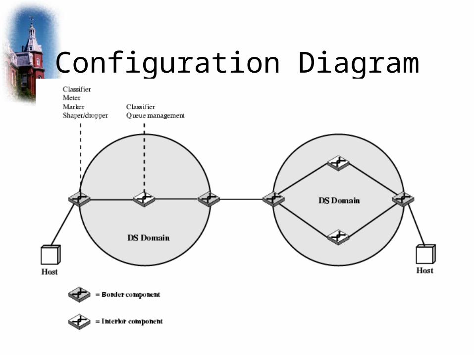
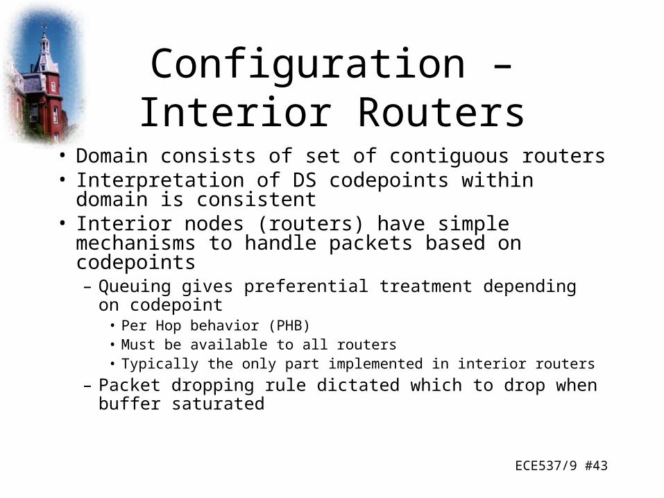
Configuration – Interior Routers
• Domain consists of set of contiguous routers• Interpretation of DS codepoints within domain is
consistent• Interior nodes (routers) have simple mechanisms to
handle packets based on codepoints– Queuing gives preferential treatment depending on
codepoint• Per Hop behavior (PHB)• Must be available to all routers• Typically the only part implemented in interior routers
– Packet dropping rule dictated which to drop when buffer saturated

ECE537/9 #44
Configuration – Boundary Routers
• Include PHB rules• Also traffic conditioning to provide desired
service– Classifier
• Separate packets into classes
– Meter• Measure traffic for conformance to profile
– Marker• Policing by remarking codepoints if required
– Shaper– Dropper

ECE537/9 #45
DS Traffic Conditioner

ECE537/9 #46
Per Hop Behavior –Expedited forwarding
• Premium service– Low loss, delay, jitter; assured bandwidth end-to-end
service through domains– Looks like point to point or leased line– Difficult to achieve– Configure nodes so traffic aggregate has well defined
minimum departure rate• EF PHB
– Condition aggregate so arrival rate at any node is always less that minimum departure rate
• Boundary conditioners

ECE537/9 #47
Per Hop Behavior –Explicit Allocation
• Superior to best efforts• Does not require reservation of resources• Does not require detailed discrimination among flows• Users offered choice of number of classes• Monitored at boundary node
– In or out depending on matching profile or not• Inside network all traffic treated as single pool of packets,
distinguished only as in or out• Drop out packets before in packets if necessary• Different levels of service because different number of in
packets for each user
ECE537/9 #48
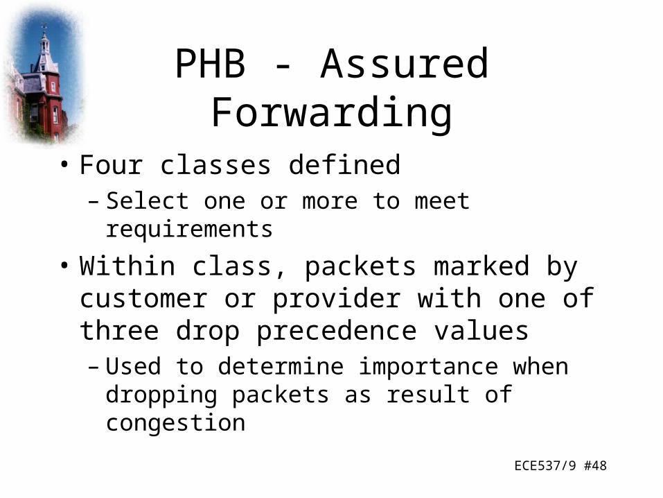
PHB - Assured Forwarding
• Four classes defined– Select one or more to meet requirements
• Within class, packets marked by customer or provider with one of three drop precedence values– Used to determine importance when dropping
packets as result of congestion

ECE537/9 #49
Codepoints for AF PHB

ECE537/9 #50
Increased Demands
• Need to incorporate bursty and stream traffic in TCP/IP architecture
• Increase capacity– Faster links, switches, routers
– Intelligent routing policies
– End-to-end flow control
• Multicasting• Quality of Service (QoS) capability• Transport protocol for streaming

ECE537/9 #51
Resource Reservation - Unicast
• Prevention as well as reaction to congestion required
• Can do this by resource reservation• Unicast
– End users agree on QoS for task and request from network
– May reserve resources
– Routers pre-allocate resources
– If QoS not available, may wait or try at reduced QoS
ECE537/9 #52
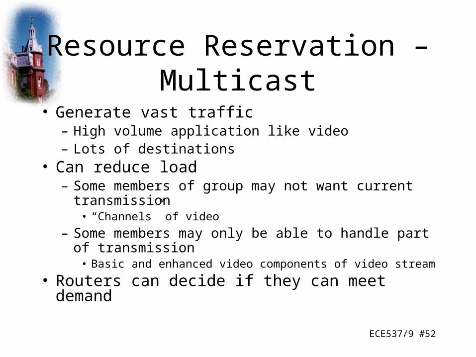
Resource Reservation – Multicast
• Generate vast traffic– High volume application like video– Lots of destinations
• Can reduce load– Some members of group may not want current
transmission• “Channels” of video
– Some members may only be able to handle part of transmission
• Basic and enhanced video components of video stream
• Routers can decide if they can meet demand
ECE537/9 #53
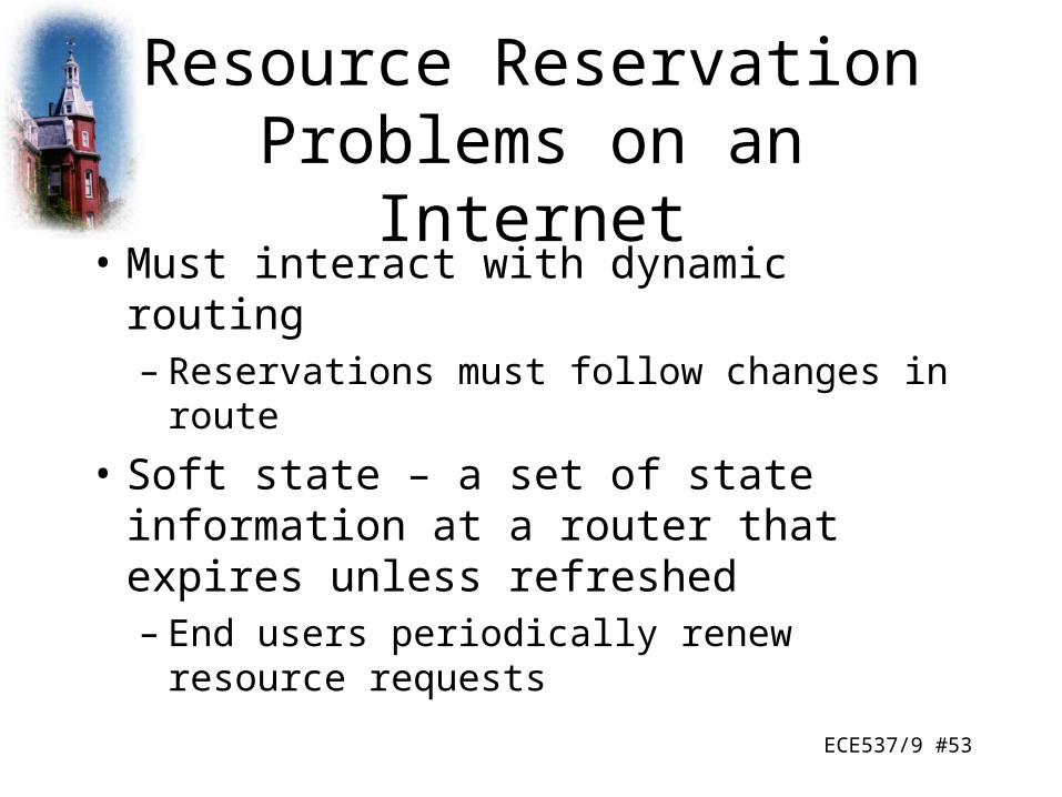
Resource Reservation Problems on an Internet
• Must interact with dynamic routing– Reservations must follow changes in route
• Soft state – a set of state information at a router that expires unless refreshed– End users periodically renew resource requests

ECE537/9 #54
Resource ReSerVation Protocol (RSVP) Design Goals
• Enable receivers to make reservations– Different reservations among members of same multicast group
allowed• Deal gracefully with changes in group membership
– Dynamic reservations, separate for each member of group• Aggregate for group should reflect resources needed
– Take into account common path to different members of group• Receivers can select one of multiple sources (channel
selection)• Deal gracefully with changes in routes
– Re-establish reservations• Control protocol overhead• Independent of routing protocol
ECE537/9 #55
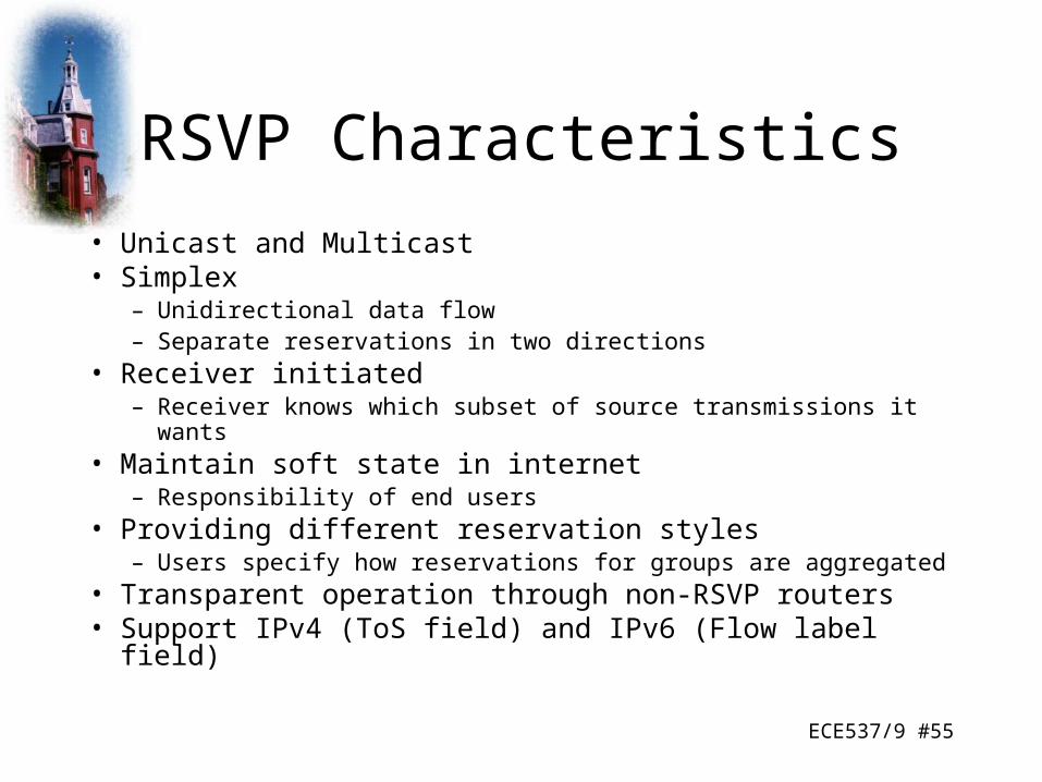
RSVP Characteristics
• Unicast and Multicast• Simplex
– Unidirectional data flow– Separate reservations in two directions
• Receiver initiated– Receiver knows which subset of source transmissions it wants
• Maintain soft state in internet– Responsibility of end users
• Providing different reservation styles– Users specify how reservations for groups are aggregated
• Transparent operation through non-RSVP routers• Support IPv4 (ToS field) and IPv6 (Flow label field)

ECE537/9 #56
Data Flows - Session
• Data flow identified by destination• Resources allocated by router for duration of
session• Defined by
– Destination IP address• Unicast or multicast
– IP protocol identifier• TCP, UDP etc.
– Destination port• May not be used in multicast

ECE537/9 #57
Flow Descriptor
• Reservation Request– Flow spec
• Desired QoS
• Used to set parameters in node’s packet scheduler
• Service class, Rspec (reserve), Tspec (traffic)
– Filter spec• Set of packets for this reservation
• Source address, source prot

ECE537/9 #58
Treatment of Packets of One Session at One Router
ECE537/9 #59
RSVP Operation Diagram

ECE537/9 #60
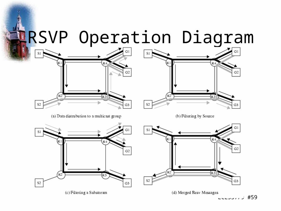
RSVP Operation
• G1, G2, G3 members of multicast group• S1, S2 sources transmitting to that group• Heavy black line is routing tree for S1, heavy grey
line for S2• Arrowed lines are packet transmission from S1
(black) and S2 (grey)• All four routers need to know reservation s for
each multicast address– Resource requests must propagate back through routing
tree

ECE537/9 #61
Filtering
• G3 has reservation filter spec including S1 and S2• G1, G2 from S1 only• R3 delivers from S2 to G3 but does not forward to R4• G1, G2 send RSVP request with filter excluding S2• G1, G2 only members of group reached through R4
– R4 doesn’t need to forward packets from this session– R4 merges filter spec requests and sends to R3
• R3 no longer forwards this session’s packets to R4– Handling of filtered packets not specified– Here they are dropped but could be best efforts delivery
• R3 needs to forward to G3– Stores filter spec but doesn’t propagate it

ECE537/9 #62
Reservation Styles
• Determines manner in which resource requirements from members of group are aggregated
• Reservation attribute– Reservation shared among senders (shared)
• Characterizing entire flow received on multicast address
– Allocated to each sender (distinct)• Simultaneously capable of receiving data flow from each sender
• Sender selection– List of sources (explicit)– All sources, no filter spec (wild card)

ECE537/9 #63
Reservation Attributes and Styles
• Reservation Attribute– Distinct
• Sender selection explicit = Fixed filter (FF)
• Sender selection wild card = none
– Shared• Sender selection explicit= Shared-explicit (SE)
• Sender selection wild card = Wild card filter (WF)
ECE537/9 #64
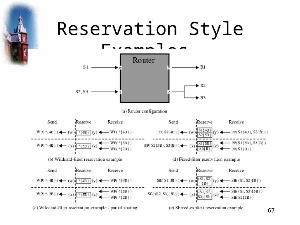
Wild Card Filter Style
• Single resource reservation shared by all senders to this address
• If used by all receivers: shared pipe whose capacity is largest of resource requests from receivers downstream from any point on tree
• Independent of number of senders using it• Propagated upstream to all senders• WF(*{Q})
– * = wild card sender– Q = flowspec
• Audio teleconferencing with multiple sites
ECE537/9 #65
Fixed Filter Style
• Distinct reservation for each sender
• Explicit list of senders
• FF(S1{Q!}, S2{Q2},…)
• Video distribution

ECE537/9 #66
Shared Explicit Style
• Single reservation shared among specific list of senders
• SE(S1, S2, S3, …{Q})
• Multicast applications with multiple data sources but unlikely to transmit simultaneously
ECE537/9 #67
Reservation Style Examples

ECE537/9 #68
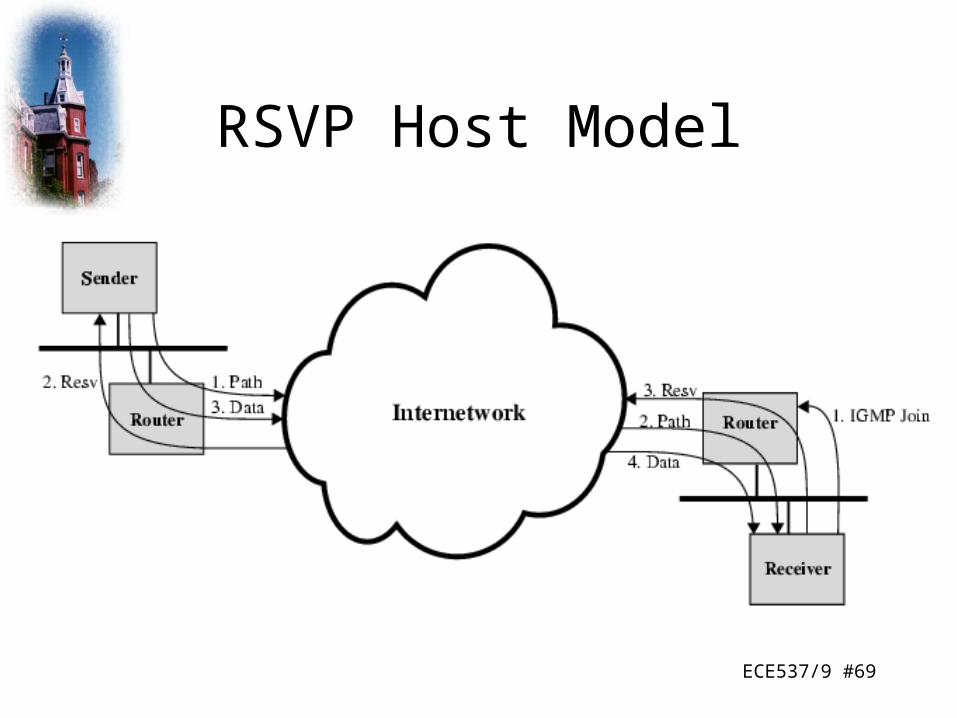
RSVP Protocol Mechanisms
• Two message types– Resv
• Originate at multicast group receivers• Propagate upstream• Merged and packet when appropriate• Create soft states• Reach sender
– Allow host to set up traffic control for first hop
– Path• Provide upstream routing information• Issued by sending hosts• Transmitted through distribution tree to all destinations
ECE537/9 #69
RSVP Host Model
ECE537/9 #70
Multiprotocol Label Switching (MPLS)
• Routing algorithms provide support for performance goals– Distributed and dynamic
• React to congestion• Load balance across network
– Based on metrics• Develop information that can be used in handling different service
needs
• Enhancements provide direct support– IS, DS, RSVP
• Nothing directly improves throughput or delay• MPLS tries to match ATM QoS support

ECE537/9 #71
Background
• Efforts to marry IP and ATM• IP switching (Ipsilon)• Tag switching (Cisco)• Aggregate route based IP switching (IBM)• Cascade (IP navigator)• All use standard routing protocols to define paths
between end points• Assign packets to path as they enter network• Use ATM switches to move packets along paths
– ATM switching (was) much faster than IP routers– Use faster technology
ECE537/9 #72
Developments
• IETF working group in 1997, proposed standard 2001
• Routers developed to be as fast as ATM switches– Remove the need to provide both technologies in same
network• MPLS does provide new capabilities
– QoS support– Traffic engineering– Virtual private networks– Multiprotocol support
ECE537/9 #73
Connection Oriented QoS Support
• Guarantee fixed capacity for specific applications• Control latency/jitter• Ensure capacity for voice• Provide specific, guaranteed quantifiable SLAs• Configure varying degrees of QoS for multiple
customers• MPLS imposes connection oriented framework on
IP based internets

ECE537/9 #74
Traffic Engineering
• Ability to dynamically define routes, plan resource commitments based on known demands and optimize network utilization
• Basic IP allows primitive traffic engineering– E.g. dynamic routing
• MPLS makes network resource commitment easy– Able to balance load in face of demand– Able to commit to different levels of support to meet user traffic
requirements– Aware of traffic flows with QoS requirements and predicted
demand– Intelligent re-routing when congested

ECE537/9 #75
VPN Support
• Traffic from a given enterprise or group passes transparently through an internet
• Segregated from other traffic on internet
• Performance guarantees
• Security

ECE537/9 #76
Multiprotocol Support
• MPLS can be used on different network technologies
• IP– Requires router upgrades
• Coexist with ordinary routers
• ATM– Enables and ordinary switches co-exist
• Frame relay– Enables and ordinary switches co-exist
• Mixed network

ECE537/9 #77
MPLS Terminology
ECE537/9 #78
MPLS Operation
• Label switched routers capable of switching and routing packets based on label appended to packet
• Labels define a flow of packets between end points or multicast destinations
• Each distinct flow (forward equivalence class – FEC) has specific path through LSRs defined– Connection oriented
• Each FEC has QoS requirements• IP header not examined
– Forward based on label value

ECE537/9 #79
MPLS Operation Diagram
ECE537/9 #80
Explanation - Setup
• Labelled switched path established prior to routing and delivery of packets
• QoS parameters established along path– Resource commitment– Queuing and discard policy at LSR– Interior routing protocol e.g. OSPF used– Labels assigned
• Local significance only• Manually or using Label distribution protocol (LDP) or
enhanced version of RSVP

ECE537/9 #81
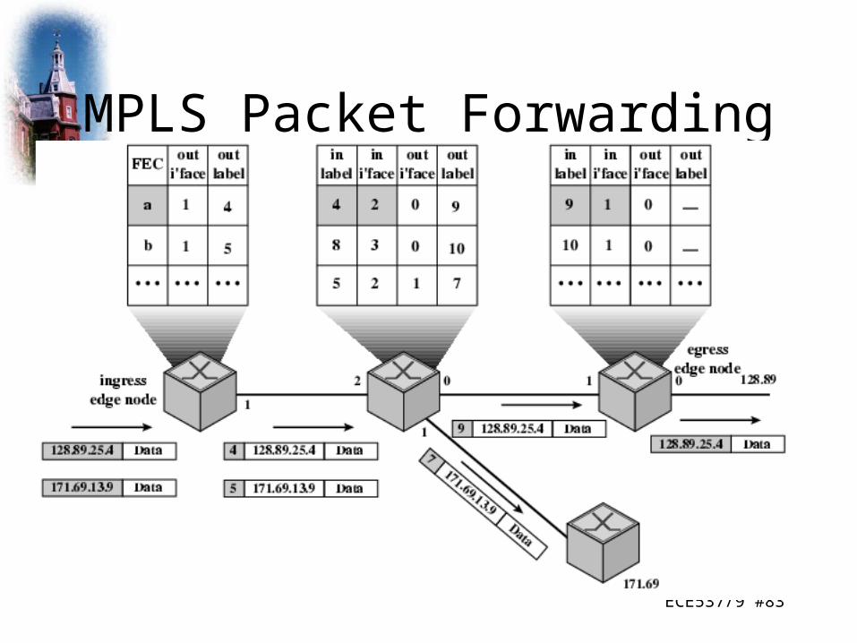
Explanation – Packet Handling
• Packet enters domain through edge LSR– Processed to determine QoS
• LSR assigns packet to FEC and hence LSP– May need co-operation to set up new LSP
• Append label• Forward packet• Within domain LSR receives packet• Remove incoming label, attach outgoing label and
forward• Egress edge strips label, reads IP header and
forwards

ECE537/9 #82
Notes
• MPLS domain is contiguous set of MPLS enabled routers• Traffic may enter or exit via direct connection to MPLS router or from
non-MPLS router• FEC determined by parameters, e.g.
– Source/destination IP address or network IP address– Port numbers– IP protocol id– Differentiated services codepoint– IPv6 flow label
• Forwarding is simple lookup in predefined table– Map label to next hop
• Can define PHB at an LSR for given FEC• Packets between same end points may belong to different FEC
ECE537/9 #83
MPLS Packet Forwarding

ECE537/9 #84
Label Stacking
• Packet may carry number of labels• LIFO (stack)
– Processing based on top label– Any LSR may push or pop label
• Unlimited levels
– Allows aggregation of LSPs into single LSP for part of route
– C.f. ATM virtual channels inside virtual paths– E.g. aggregate all enterprise traffic into one LSP for
access provider to handle– Reduces size of tables
ECE537/9 #85
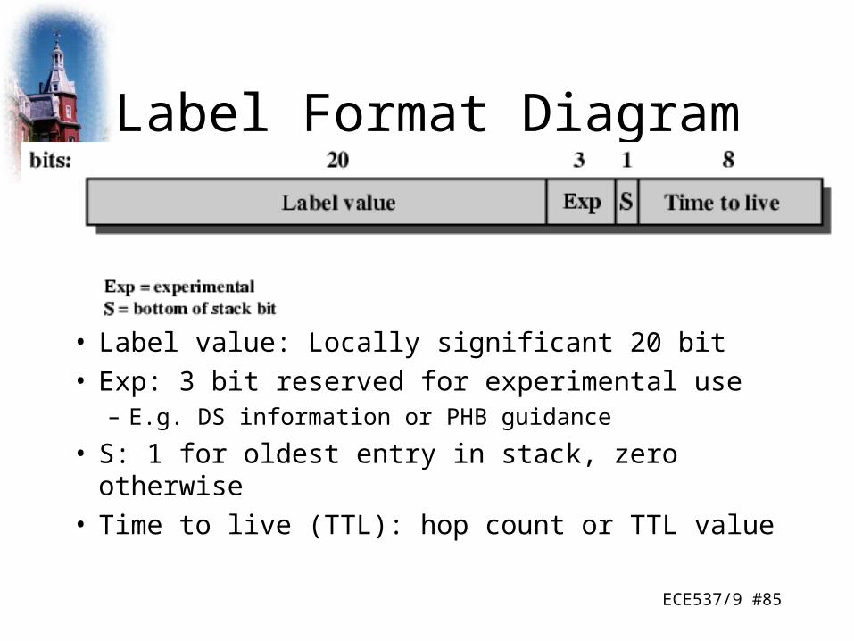
Label Format Diagram
• Label value: Locally significant 20 bit• Exp: 3 bit reserved for experimental use
– E.g. DS information or PHB guidance
• S: 1 for oldest entry in stack, zero otherwise• Time to live (TTL): hop count or TTL value

ECE537/9 #86
Time to Live Processing
• Needed to support TTL since IP header not read• First label TTL set to IP header TTL on entry to MPLS
domain• TTL of top entry on stack decremented at internal LSR
– If zero, packet dropped or passed to ordinary error processing (e.g. ICMP)
– If positive, value placed in TTL of top label on stack and packet forwarded
• At exit from domain, (single stack entry) TTL decremented– If zero, as above– If positive, placed in TTL field of Ip header and forwarded
ECE537/9 #87
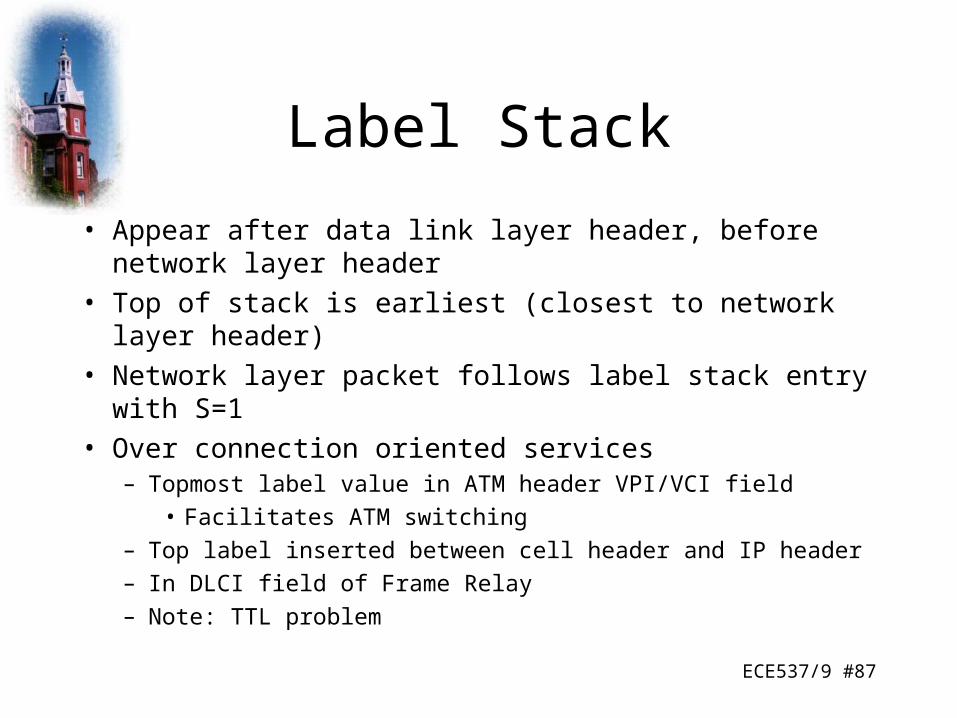
Label Stack
• Appear after data link layer header, before network layer header
• Top of stack is earliest (closest to network layer header)
• Network layer packet follows label stack entry with S=1
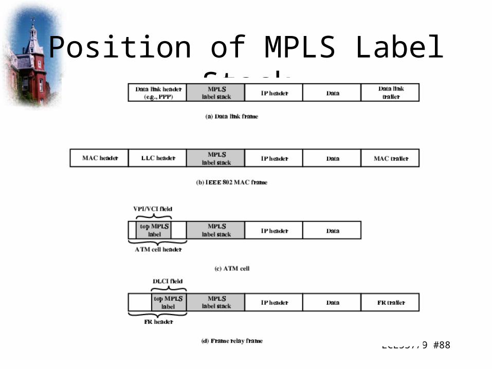
• Over connection oriented services– Topmost label value in ATM header VPI/VCI field
• Facilitates ATM switching
– Top label inserted between cell header and IP header
– In DLCI field of Frame Relay
– Note: TTL problem
ECE537/9 #88
Position of MPLS Label Stack

ECE537/9 #89
FECs, LSPs, and Labels
• Traffic grouped into FECs• Traffic in a FEC transits an MLPS domain along an LSP• Packets identified by locally significant label• At each LSR, labelled packets forwarded on basis of label.
– LSR replaces incoming label with outgoing label• Each flow must be assigned to a FEC• Routing protocol must determine topology and current
conditions so LSP can be assigned to FEC– Must be able to gather and use information to support QoS
• LSRs must be aware of LSP for given FEC, assign incoming label to LSP, communicate label to other LSRs
ECE537/9 #90
Topology of LSPs
• Unique ingress and egress LSR– Single path through domain
• Unique egress, multiple ingress LSRs– Multiple paths, possibly sharing final few hops
• Multiple egress LSRs for unicast traffic
• Multicast
ECE537/9 #91
Route Selection
• Selection of LSP for particular FEC• Hop-by-hop
– LSR independently chooses next hop
– Ordinary routing protocols e.g. OSPF
– Doesn’t support traffic engineering or policy routing
• Explicit– LSR (usually ingress or egress) specifies some or all
LSRs in LSP for given FEC
– Selected by configuration,or dynamically

ECE537/9 #92
Constraint Based Routing Algorithm
• Take in to account traffic requirements of flows and resources available along hops– Current utilization, existing capacity, committed
services
– Additional metrics over and above traditional routing protocols (OSPF)
• Max link data rate
• Current capacity reservation
• Packet loss ratio
• Link propagation delay
ECE537/9 #93
Label Distribution
• Setting up LSP
• Assign label to LSP
• Inform all potential upstream nodes of label assigned by LSR to FEC– Allows proper packet labelling– Learn next hop for LSP and label that
downstream node has assigned to FEC• Allow LSR to map incoming to outgoing label
ECE537/9 #94
Real Time Transport Protocol
• TCP not suited to real time distributed application– Point to point so not suitable for multicast– Retransmitted segments arrive out of order– No way to associate timing with segments
• UDP does not include timing information nor any support for real time applications
• Solution is real-time transport protocol RTP
ECE537/9 #95
RTP Architecture
• Close coupling between protocol and application layer functionality– Framework for application to implement single
protocol
• Application level framing
• Integrated layer processing
ECE537/9 #96
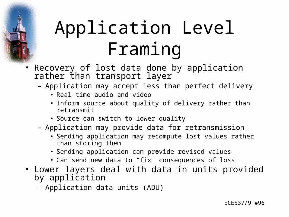
Application Level Framing
• Recovery of lost data done by application rather than transport layer– Application may accept less than perfect delivery
• Real time audio and video• Inform source about quality of delivery rather than retransmit• Source can switch to lower quality
– Application may provide data for retransmission• Sending application may recompute lost values rather than storing them• Sending application can provide revised values• Can send new data to “fix” consequences of loss
• Lower layers deal with data in units provided by application– Application data units (ADU)
ECE537/9 #97
Integrated Layer Processing
• Adjacent layers in protocol stack tightly coupled
• Allows out of order or parallel functions from different layers
ECE537/9 #98
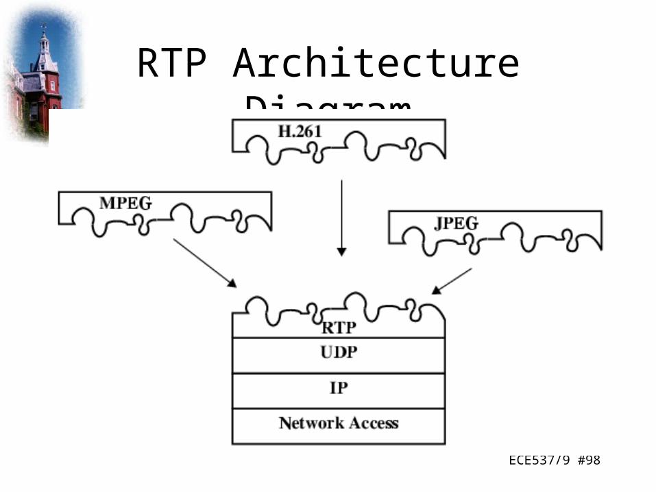
RTP Architecture Diagram
ECE537/9 #99
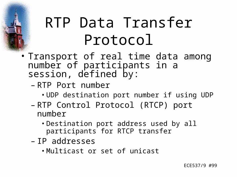
RTP Data Transfer Protocol
• Transport of real time data among number of participants in a session, defined by:– RTP Port number
• UDP destination port number if using UDP
– RTP Control Protocol (RTCP) port number • Destination port address used by all participants for
RTCP transfer
– IP addresses• Multicast or set of unicast

ECE537/9 #100
Multicast Support
• Each RTP data unit includes:
• Source identifier
• Timestamp
• Payload format
ECE537/9 #101
Relays
• Intermediate system acting as receiver and transmitter for given protocol layer
• Mixers– Receives streams of RTP packets from one or more
sources– Combines streams– Forwards new stream
• Translators– Produce one or more outgoing RTP packets for each
incoming packet– E.g. convert video to lower quality

ECE537/9 #102
RTP Header
ECE537/9 #103
RTP Control Protocol (RTCP)
• RTP is for user data
• RTCP is multicast provision of feedback to sources and session participants
• Uses same underlying transport protocol (usually UDP) and different port number
• RTCP packet issued periodically by each participant to other session members
ECE537/9 #104
RTCP Functions
• QoS and congestion control
• Identification
• Session size estimation and scaling
• Session control
ECE537/9 #105
RTCP Transmission
• Number of separate RTCP packets bundled in single UDP datagram– Sender report– Receiver report– Source description– Goodbye– Application specific

ECE537/9 #106
RTCP Packet Formats

ECE537/9 #107
Packet Fields (All Packets)
• Version (2 bit) currently version 2• Padding (1 bit) indicates padding bits at end of
control information, with number of octets as last octet of padding
• Count (5 bit) of reception report blocks in SR or RR, or source items in SDES or BYE
• Packet type (8 bit)• Length (16 bit) in 32 bit words minus 1• In addition Sender and receiver reports have:
– Synchronization Source Identifier
ECE537/9 #108
Packet Fields (Sender Report)Sender Information Block
• NTP timestamp: absolute wall clock time when report sent
• RTP Timestamp: Relative time used to create timestamps in RTP packets
• Sender’s packet count (for this session)
• Sender’s octet count (for this session)

ECE537/9 #109
Packet Fields (Sender Report)Reception Report Block
• SSRC_n (32 bit) identifies source refered to by this report block
• Fraction lost (8 bits) since previous SR or RR• Cumulative number of packets lost (24 bit) during this
session• Extended highest sequence number received (32 bit)
– Least significant 16 bits is highest RTP data sequence number received from SSRC_n
– Most significant 16 bits is number of times sequence number has wrapped to zero
• Interarrival jitter (32 bit)• Last SR timestamp (32 bit)• Delay since last SR (32 bit)

ECE537/9 #110
Receiver Report
• Same as sender report except:– Packet type field has different value– No sender information block
ECE537/9 #111
Source Description Packet
• Used by source to give more information• 32 bit header followed by zero or more
additional information chunks• E.g.:• 0 END End of SDES list• 1 CNAME Canonical name• 2 NAME Real user name of source• 3 EMAIL Email address

ECE537/9 #112
Goodbye (BYE)
• Indicates one or more sources no linger active– Confirms departure rather than failure of
network
ECE537/9 #113
Application Defined Packet
• Experimental use
• For functions & features that are application specific
ECE537/9 #114
Summary
• There are an increasing number of approaches for providing minimum levels of service over packet networks
• Many of these schemes do not fit nicely into the n-layer protocol model (e.g. MPLS)
• Many of these schemes do not interoperate well with one another, so decisions must be taken about implementation

ECE537/8 #115Spring 2009© 2000-2009, Richard A. Stanley
Homework
• Compare and contrast label switching with Layer 2 and Layer 3 packet switching. What are the advantages and disadvantages of each? When and where might one be preferred over the other?
• Be prepared to discuss your findings with the class for 5-10 minutes next week. You may use slides if you desire.
ECE537/8 #116Spring 2009© 2000-2009, Richard A. Stanley
Disclaimer
• Parts of the lecture slides contain original work of William Stallings and Prentice-Hall, and remain copyrighted materials by the original owner(s). The slides are intended for the sole purpose of instruction in computer networks at Worcester Polytechnic Institute.