Ece254 Manual 2013sep09
114
ECE254 Operating Systems and System Programming Lab Manual by Yiqing Huang Paul A.S. Ward Electrical and Computer Engineering Department University of Waterloo Waterloo, Ontario, Canada, 2013 c Y. Huang, and P.A.S. Ward 2013
-
Upload
jessica-james -
Category
Documents
-
view
94 -
download
1
description
computer manaul
Transcript of Ece254 Manual 2013sep09

ECE254 Operating Systems andSystem Programming Lab Manual
by
Yiqing Huang
Paul A.S. Ward
Electrical and Computer Engineering DepartmentUniversity of Waterloo
Waterloo, Ontario, Canada, 2013
c© Y. Huang, and P.A.S. Ward 2013

Acknowledgments
We would like to sincerely thank our students who took ECE254 and MTE241 courses inthe past two years. They provided constructive feedback every term to make the manualmore useful to address problems that students would encounter when working on each labassignment.
Special thank goes to Dr. Thomas Reidemeister who shared his prototyping work inSE350 course project on Keil MCB1700 boards with us.
We are grateful to teaching assistants Bo Zhu, Dr. Nabil Drawil, Pei Wang and ShashaZhu who provided valuable feedback and improved lab tutorials.
Dr. Ajit Singh, Dr. Rodolfo Pellizzoni, and Douglas W. Harder in the Electrical andComputer Engineering department have provided valuable laboratory project improve-ment feedback. Dr. Pellizzoni proof-read the entire manual meticulously. Douglas W.Harder also carefully proof-read descriptions of each lab. We warmly acknowledge theircontributions.
The project and manual won’t be possible without lab facilities. Thank Roger Sander-son for providing us with lab tools and resources. Our gratitude also goes out to Eric Praet-zel who sets up the Keil boards in lab and maintains the Keil software on Nexus machines;Laura Winger who managed to customize the boards so that we have the neat plastic coverto protect our hardware. We appreciate that Bernie Roehl and Rasoul Keshavarzi-Valdanihave shared their valuable Keil board experiences with us. Bob Boy from ARM alwaysanswers our questions in a detailed and timely manner. Thank everyone who has helped.
ii

Contents
List of Tables viii
List of Figures xi
Preface i
I Development Environment 1
1 Introduction to ECE Linux Programming Environment 2
1.1 Linux Hardware Environment . . . . . . . . . . . . . . . . . . . . . . . . . 2
1.2 How to Connect to Linux Servers . . . . . . . . . . . . . . . . . . . . . . . 2
1.3 Work Environment Setup . . . . . . . . . . . . . . . . . . . . . . . . . . . 3
1.3.1 Setting up Remote Linux Graphic Support . . . . . . . . . . . . . . 3
1.3.2 Mapping Linux Account on Nexus . . . . . . . . . . . . . . . . . . . 4
1.4 Basic Software Development Tools . . . . . . . . . . . . . . . . . . . . . . . 6
1.4.1 Editor . . . . . . . . . . . . . . . . . . . . . . . . . . . . . . . . . . 6
1.4.2 C Compiler . . . . . . . . . . . . . . . . . . . . . . . . . . . . . . . 7
1.4.3 Debugger . . . . . . . . . . . . . . . . . . . . . . . . . . . . . . . . 7
1.5 More on Development Tools . . . . . . . . . . . . . . . . . . . . . . . . . . 8
1.5.1 How to Automate Build . . . . . . . . . . . . . . . . . . . . . . . . 8
1.5.2 Version Control Software . . . . . . . . . . . . . . . . . . . . . . . . 10
1.5.3 Integrated Development Environment . . . . . . . . . . . . . . . . . 11
1.6 Man Page . . . . . . . . . . . . . . . . . . . . . . . . . . . . . . . . . . . . 11
iii

2 Keil MCB1700 Hardware Environment 13
2.1 MCB1700 Board Overview . . . . . . . . . . . . . . . . . . . . . . . . . . . 13
2.2 Cortex-M3 Processor . . . . . . . . . . . . . . . . . . . . . . . . . . . . . . 13
2.2.1 Registers . . . . . . . . . . . . . . . . . . . . . . . . . . . . . . . . . 16
2.2.2 Processor mode and privilege levels . . . . . . . . . . . . . . . . . . 18
2.2.3 Stacks . . . . . . . . . . . . . . . . . . . . . . . . . . . . . . . . . . 19
2.3 Memory Map . . . . . . . . . . . . . . . . . . . . . . . . . . . . . . . . . . 19
2.4 Exceptions and Interrupts . . . . . . . . . . . . . . . . . . . . . . . . . . . 20
2.4.1 Vector Table . . . . . . . . . . . . . . . . . . . . . . . . . . . . . . . 20
2.4.2 Exception Entry . . . . . . . . . . . . . . . . . . . . . . . . . . . . 20
2.4.3 EXC RETURN Value . . . . . . . . . . . . . . . . . . . . . . . . . . . . 23
2.4.4 Exception Return . . . . . . . . . . . . . . . . . . . . . . . . . . . . 23
2.5 Data Types . . . . . . . . . . . . . . . . . . . . . . . . . . . . . . . . . . . 24
3 Keil Software Development Tools 25
3.1 Install MDK-ARM on your own computer . . . . . . . . . . . . . . . . . . 25
3.2 Creating an Application in µVision4 IDE . . . . . . . . . . . . . . . . . . 27
3.2.1 Create a New Project . . . . . . . . . . . . . . . . . . . . . . . . . . 27
3.2.2 Managing Project Components . . . . . . . . . . . . . . . . . . . . 29
3.2.3 Build and Download . . . . . . . . . . . . . . . . . . . . . . . . . . 32
3.3 Debugging . . . . . . . . . . . . . . . . . . . . . . . . . . . . . . . . . . . . 34
3.3.1 Disabling CRP . . . . . . . . . . . . . . . . . . . . . . . . . . . . . 34
3.3.2 Simulation . . . . . . . . . . . . . . . . . . . . . . . . . . . . . . . . 36
3.3.3 Configure In-Memory Execution Using ULINK Cortex Debugger . . 36
4 ARM RL-RTX 38
4.1 Creating an RTX Application . . . . . . . . . . . . . . . . . . . . . . . . . 38
4.2 Building an ARM RL-RTX Library from Source . . . . . . . . . . . . . . . 42
4.3 Creating an RTX Application with a Self-built RTX Library . . . . . . . . 44
iv
5 Programming MCB1700 51
5.1 The Thumb-2 Instruction Set Architecture . . . . . . . . . . . . . . . . . . 51
5.2 ARM Architecture Procedure Call Standard (AAPCS) . . . . . . . . . . . 51
5.3 Cortex Microcontroller Software Interface Standard (CMSIS) . . . . . . . . 54
5.3.1 CMSIS files . . . . . . . . . . . . . . . . . . . . . . . . . . . . . . . 55
5.3.2 Cortex-M Core Peripherals . . . . . . . . . . . . . . . . . . . . . . . 55
5.3.3 System Exceptions . . . . . . . . . . . . . . . . . . . . . . . . . . . 57
5.3.4 Intrinsic Functions . . . . . . . . . . . . . . . . . . . . . . . . . . . 57
5.3.5 Vendor Peripherals . . . . . . . . . . . . . . . . . . . . . . . . . . . 57
5.4 Accessing C Symbols from Assembly . . . . . . . . . . . . . . . . . . . . . 58
5.5 SVC Programming: Adding a Function to RTX API . . . . . . . . . . . . 60
II Laboratory Projects 63
6 Lab Administration Policy 64
6.1 Group Lab Policy . . . . . . . . . . . . . . . . . . . . . . . . . . . . . . . . 64
6.2 Lab Assignments Deadline Policy. . . . . . . . . . . . . . . . . . . . . . . . 65
6.3 Lab Grading Policy . . . . . . . . . . . . . . . . . . . . . . . . . . . . . . . 65
6.4 Lab Facility After Hour Access Policy . . . . . . . . . . . . . . . . . . . . . 65
7 Lab0-A: Introduction to Linux System Programming 67
7.1 Objective . . . . . . . . . . . . . . . . . . . . . . . . . . . . . . . . . . . . 67
7.2 Starter Files . . . . . . . . . . . . . . . . . . . . . . . . . . . . . . . . . . . 67
7.3 Pre-lab Preparation . . . . . . . . . . . . . . . . . . . . . . . . . . . . . . . 68
7.4 Warm-up Exercises . . . . . . . . . . . . . . . . . . . . . . . . . . . . . . . 68
7.5 Lab0-A Assignment . . . . . . . . . . . . . . . . . . . . . . . . . . . . . . . 69
7.6 Deliverables . . . . . . . . . . . . . . . . . . . . . . . . . . . . . . . . . . . 69
7.6.1 Pre-lab Deliverables . . . . . . . . . . . . . . . . . . . . . . . . . . 69
7.6.2 Post-lab Deliverables . . . . . . . . . . . . . . . . . . . . . . . . . . 70
7.7 Marking Rubric . . . . . . . . . . . . . . . . . . . . . . . . . . . . . . . . . 70
v

8 Lab0-B: Introduction to ARM RL-RTX Kernel and Application Pro-gramming 71
8.1 Objective . . . . . . . . . . . . . . . . . . . . . . . . . . . . . . . . . . . . 71
8.2 Starter Files . . . . . . . . . . . . . . . . . . . . . . . . . . . . . . . . . . . 71
8.3 Pre-lab Preparation . . . . . . . . . . . . . . . . . . . . . . . . . . . . . . . 72
8.4 Warm-up Exercises . . . . . . . . . . . . . . . . . . . . . . . . . . . . . . . 72
8.4.1 Download the HelloWorld to the Board . . . . . . . . . . . . . . . . 72
8.4.2 Creating an RL-RTX Application . . . . . . . . . . . . . . . . . . . 72
8.4.3 A HelloWorld Application Linked with Your Own RTX . . . . . . . 73
8.5 Lab0-B Assignment . . . . . . . . . . . . . . . . . . . . . . . . . . . . . . . 73
8.5.1 Questions . . . . . . . . . . . . . . . . . . . . . . . . . . . . . . . . 73
8.5.2 Programming Project . . . . . . . . . . . . . . . . . . . . . . . . . . 73
8.6 Deliverables . . . . . . . . . . . . . . . . . . . . . . . . . . . . . . . . . . . 73
8.6.1 Pre-lab Deliverables . . . . . . . . . . . . . . . . . . . . . . . . . . 73
8.6.2 Post-lab Deliverables . . . . . . . . . . . . . . . . . . . . . . . . . . 74
8.7 Marking Rubric . . . . . . . . . . . . . . . . . . . . . . . . . . . . . . . . . 74
9 Lab1: Task Management in RL-RTX 75
9.1 Objective . . . . . . . . . . . . . . . . . . . . . . . . . . . . . . . . . . . . 75
9.2 Starter files . . . . . . . . . . . . . . . . . . . . . . . . . . . . . . . . . . . 75
9.3 Pre-lab Preparation . . . . . . . . . . . . . . . . . . . . . . . . . . . . . . . 75
9.4 Lab1 Assignment . . . . . . . . . . . . . . . . . . . . . . . . . . . . . . . . 76
9.4.1 Part A . . . . . . . . . . . . . . . . . . . . . . . . . . . . . . . . . . 76
9.4.2 Part B . . . . . . . . . . . . . . . . . . . . . . . . . . . . . . . . . . 78
9.5 Deliverables . . . . . . . . . . . . . . . . . . . . . . . . . . . . . . . . . . . 79
9.5.1 Pre-Lab Deliverables . . . . . . . . . . . . . . . . . . . . . . . . . . 79
9.5.2 Post-Lab Deliverables . . . . . . . . . . . . . . . . . . . . . . . . . . 79
9.6 Marking Rubric . . . . . . . . . . . . . . . . . . . . . . . . . . . . . . . . . 80
vi
10 Lab2: Inter-process Communication by Message Passing 81
10.1 Objective . . . . . . . . . . . . . . . . . . . . . . . . . . . . . . . . . . . . 81
10.2 Starter files . . . . . . . . . . . . . . . . . . . . . . . . . . . . . . . . . . . 81
10.3 Pre-lab Preparation . . . . . . . . . . . . . . . . . . . . . . . . . . . . . . . 82
10.4 Lab2 Assignment . . . . . . . . . . . . . . . . . . . . . . . . . . . . . . . . 82
10.5 Deliverables . . . . . . . . . . . . . . . . . . . . . . . . . . . . . . . . . . . 85
10.6 Pre-lab Deliverables . . . . . . . . . . . . . . . . . . . . . . . . . . . . . . . 85
10.7 Post-lab Deliverables . . . . . . . . . . . . . . . . . . . . . . . . . . . . . . 85
10.8 Report Marking Rubric . . . . . . . . . . . . . . . . . . . . . . . . . . . . . 87
11 Lab3: Thread Concurrency Control 88
11.1 Objective . . . . . . . . . . . . . . . . . . . . . . . . . . . . . . . . . . . . 88
11.2 Starter files . . . . . . . . . . . . . . . . . . . . . . . . . . . . . . . . . . . 89
11.3 Pre-lab Preparation . . . . . . . . . . . . . . . . . . . . . . . . . . . . . . . 89
11.4 Lab3 Assignment . . . . . . . . . . . . . . . . . . . . . . . . . . . . . . . . 89
11.5 Deliverables . . . . . . . . . . . . . . . . . . . . . . . . . . . . . . . . . . . 91
11.5.1 Pre-lab Deliverables . . . . . . . . . . . . . . . . . . . . . . . . . . 91
11.5.2 Post-lab Deliverables . . . . . . . . . . . . . . . . . . . . . . . . . . 91
11.6 Report Marking Rubric . . . . . . . . . . . . . . . . . . . . . . . . . . . . . 93
12 Lab4: Porting POSIX Message Queue to ARM RL-RTX 95
12.1 Objective . . . . . . . . . . . . . . . . . . . . . . . . . . . . . . . . . . . . 95
12.2 Pre-lab Preparation . . . . . . . . . . . . . . . . . . . . . . . . . . . . . . . 95
12.3 Lab4 Assignment . . . . . . . . . . . . . . . . . . . . . . . . . . . . . . . . 96
12.4 Lab Deliverables . . . . . . . . . . . . . . . . . . . . . . . . . . . . . . . . 98
12.4.1 Pre-Lab Deliverables . . . . . . . . . . . . . . . . . . . . . . . . . . 98
12.4.2 Post-Lab Deliverables . . . . . . . . . . . . . . . . . . . . . . . . . . 98
A Forms 99
References 101
vii

List of Tables
1.1 Programming Steps and Tools . . . . . . . . . . . . . . . . . . . . . . . . . 6
2.1 Summary of processor mode, execution privilege level, and stack use options 19
2.2 LPC1768 Memory Map . . . . . . . . . . . . . . . . . . . . . . . . . . . . . 20
2.3 LPC1768 Exception and Interrupt Table . . . . . . . . . . . . . . . . . . . 21
2.4 EXC RETURN bit fields . . . . . . . . . . . . . . . . . . . . . . . . . . . . . . 23
2.5 EXC RETURN Values on Cortex-M3 . . . . . . . . . . . . . . . . . . . . . . . 23
5.1 Assembler instruction examples . . . . . . . . . . . . . . . . . . . . . . . . 52
5.2 Core Registers and AAPCS Usage . . . . . . . . . . . . . . . . . . . . . . . 53
5.3 CMSIS intrinsic functions . . . . . . . . . . . . . . . . . . . . . . . . . . . 58
6.1 Lab Weight . . . . . . . . . . . . . . . . . . . . . . . . . . . . . . . . . . . 66
8.1 Lab0-B Marking Rubric . . . . . . . . . . . . . . . . . . . . . . . . . . . . 74
9.1 Lab1 Marking Rubric . . . . . . . . . . . . . . . . . . . . . . . . . . . . . . 80
10.1 Timing measurement data table for given (N,B) values on Linux. . . . . . 86
10.2 Lab2 Marking Rubric . . . . . . . . . . . . . . . . . . . . . . . . . . . . . . 87
11.1 Timing measurement data table for given (P,C,N,B) values. . . . . . . . 92
11.2 Lab3 Marking Rubric . . . . . . . . . . . . . . . . . . . . . . . . . . . . . . 94
12.1 Timing measurement data table for given (P,C,N,B) values. . . . . . . . 97
viii

List of Figures
1.1 Invoking Terminal Clients on an ECE Nexus PC . . . . . . . . . . . . . . 3
1.2 Invoking Xming on an ECE Nexus Computer . . . . . . . . . . . . . . . . 4
1.3 SSH Secure Shell Client X11 Setting . . . . . . . . . . . . . . . . . . . . . 4
1.4 PuTTY X11 Forwarding Setting . . . . . . . . . . . . . . . . . . . . . . . . 5
1.5 SSH Secure Shell Client X11 Setting . . . . . . . . . . . . . . . . . . . . . 5
2.1 MCB1700 Board Components . . . . . . . . . . . . . . . . . . . . . . . . . 14
2.2 MCB1700 Board Block Diagram . . . . . . . . . . . . . . . . . . . . . . . . 14
2.3 LPC1768 Block Diagram . . . . . . . . . . . . . . . . . . . . . . . . . . . . 15
2.4 Simplified Cortex-M3 Block Diagram . . . . . . . . . . . . . . . . . . . . . 16
2.5 Cortex-M3 Registers . . . . . . . . . . . . . . . . . . . . . . . . . . . . . . 17
2.6 Cortex-M3 Operating Mode and Privilege Level . . . . . . . . . . . . . . . 18
2.7 Cortex-M3 Exception Stack Frame . . . . . . . . . . . . . . . . . . . . . . 22
3.1 MDK-ARM Installation Steps: Choose Example Projects . . . . . . . . . . 26
3.2 MDK-ARM Installation Steps: Finish . . . . . . . . . . . . . . . . . . . . . 26
3.3 MDK-ARM Installation Steps: ULINK Pro Driver . . . . . . . . . . . . . . 27
3.4 Keil IDE: Create a New Project . . . . . . . . . . . . . . . . . . . . . . . . 28
3.5 Keil IDE: Choose MCU . . . . . . . . . . . . . . . . . . . . . . . . . . . . 28
3.6 Keil IDE: Copy Startup Code . . . . . . . . . . . . . . . . . . . . . . . . . 29
3.7 Keil IDE: A default new project . . . . . . . . . . . . . . . . . . . . . . . . 29
3.8 Keil IDE: Manage Project Components . . . . . . . . . . . . . . . . . . . . 30
3.9 Keil IDE: Manage Components Window . . . . . . . . . . . . . . . . . . . 30
ix

3.10 Keil IDE: Updated Project Profile . . . . . . . . . . . . . . . . . . . . . . . 30
3.11 Keil IDE: Add Source File to Source Group . . . . . . . . . . . . . . . . . 31
3.12 Keil IDE: Updated Project Profile . . . . . . . . . . . . . . . . . . . . . . . 31
3.13 Keil IDE: Create New File . . . . . . . . . . . . . . . . . . . . . . . . . . . 32
3.14 Keil IDE: Final Project Setting . . . . . . . . . . . . . . . . . . . . . . . . 32
3.15 Keil IDE: Build Target . . . . . . . . . . . . . . . . . . . . . . . . . . . . . 33
3.16 Keil IDE: Build Target . . . . . . . . . . . . . . . . . . . . . . . . . . . . . 33
3.17 Keil IDE: Download Target to Flash . . . . . . . . . . . . . . . . . . . . . 33
3.18 Keil IDE: Debugging . . . . . . . . . . . . . . . . . . . . . . . . . . . . . . 35
3.19 startup LPC17xx.s excerpt . . . . . . . . . . . . . . . . . . . . . . . . . . 35
3.20 Keil IDE: Using Simulator for Debugging . . . . . . . . . . . . . . . . . . . 35
3.21 Keil IDE: Using Simulator for Debugging . . . . . . . . . . . . . . . . . . . 36
3.22 Keil IDE: Using ULINK Cortex Debugger . . . . . . . . . . . . . . . . . . 36
3.23 Keil IDE: Configure for In-Memory Execution . . . . . . . . . . . . . . . . 37
4.1 Keil IDE: Using RTX Kernel . . . . . . . . . . . . . . . . . . . . . . . . . . 39
4.2 Configuring RTX Kernel . . . . . . . . . . . . . . . . . . . . . . . . . . . . 39
4.3 Keil IDE: RTX HelloWorld Project Files . . . . . . . . . . . . . . . . . . . 40
4.4 Keil IDE: RTX Kernel Help File . . . . . . . . . . . . . . . . . . . . . . . . 42
4.5 RTX Library Source Files for Cortex-M3 . . . . . . . . . . . . . . . . . . . 43
4.6 RTX Library Project Components for Cortex-M3 . . . . . . . . . . . . . . 44
4.7 Keil IDE: Create New Multi-Project Worksapce . . . . . . . . . . . . . . . 45
4.8 Keil IDE: Naming a New Multi-Project Worksapce . . . . . . . . . . . . . 46
4.9 Keil IDE: Adding a µVision Project into Worksapce . . . . . . . . . . . . 46
4.10 Keil IDE: Adding RTX CM Lib.uvproj into Worksapce . . . . . . . . . . . . 47
4.11 Keil IDE: Adding RTX HelloWorld.uvproj into Worksapce . . . . . . . . . 47
4.12 Keil IDE: Workspace with Two Projects . . . . . . . . . . . . . . . . . . . 48
4.13 Keil IDE: Batch Build . . . . . . . . . . . . . . . . . . . . . . . . . . . . . 48
4.14 Keil IDE: Set an Active Project . . . . . . . . . . . . . . . . . . . . . . . . 49
4.15 Keil IDE: Removing Linkage with Stocked RTX Library . . . . . . . . . . 49
x

4.16 Keil IDE: Adding a Your Own RTX Library . . . . . . . . . . . . . . . . . 49
4.17 Keil IDE: Including Your Own RTL.h . . . . . . . . . . . . . . . . . . . . 50
5.1 Role of CMSIS . . . . . . . . . . . . . . . . . . . . . . . . . . . . . . . . . 54
5.2 CMSIS Organization . . . . . . . . . . . . . . . . . . . . . . . . . . . . . . 55
5.3 CMSIS Organization . . . . . . . . . . . . . . . . . . . . . . . . . . . . . . 56
5.4 CMSIS NVIC Functions . . . . . . . . . . . . . . . . . . . . . . . . . . . . 56
5.5 SVC as a Gateway for OS Functions [8] . . . . . . . . . . . . . . . . . . . . 60
10.1 Pseudo code screen shot taken from [7] . . . . . . . . . . . . . . . . . . . . 84
xi

Preface
Two operating systems are used in ECE254 laboratories. One is the general purposeoperating system Linux that supports AMD processors on personal computers. The secondis the ARM RL-RTX that supports ARM Cortex-M3 processors on Keil MCB1700 boards.
The Linux computing environment is for practicing system programming aspect of thecourse. The ARM RL-RTX, a real-time operating system library, is for practicing theoperating system kernel programming aspect of the course.
The main purpose of this document is a quick reference guide of the relevant develop-ment tools for completing laboratory projects. The second purpose of this document is toprovide the descriptions of each laboratory project.
Hence this document is organized in two parts. Part I is the reference guide of thedevelopment tools for Linux and ARM RL-RTX.
• Software Development Tools on Linux
– Linux hardware environment
– Editors
– Compiler
– Debugger
– Utility to automate build
– Utility for version control
• Keil MCB1700 Development Hardware Environment and Software Tools
– Keil MCB1700 hardware environment
– Keil MCB1700 software development Tools
– Programming MCB1700 with ARM RL-RTX
∗ Building an RTX application
i

∗ Building a customized ARM RL-RTX library
∗ Creating an application with customized ARM RL-RTX library
– Programming MCB1700
Part II is a set of course laboratory projects. When the lab weight is 30% of the coursegrade, Lab4 is not required.
• Lab0A: Introduction to Linux system programming
• Lab0B: Introduction to ARM RL-RTX kernel and application programming
• Lab1: Task management in ARM RL-RTX
• Lab2: Inter-process communication by message passing
• Lab3: Thread concurrency control
• Lab4: Porting POSIX message queue to ARM RL-RTX
This lab manual may also be used for MTE241 laboratory projects.
Use of the lab after hours is a privilege, not a right. Loss, damage, improper useof equipment, or indication of food or beverage consumption in the lab will lead to thecancellation of after-hour access.
ii

Part I
Development Environment
1

Chapter 1
Introduction to ECE LinuxProgramming Environment
1.1 Linux Hardware Environment
There are ten Linux servers that are open to ECE undergraduate students. They areecelinux1.uwaterloo.ca - ecelinux4.uwaterloo.ca and ecelinux6.uwaterloo.ca -ecelinux11.uwaterloo.ca. The ecelinux1-4 can be accessed off-campus as well as oncampus. The rest of these machines are only accessible on-campus and consoles are locatedat E5-5038 whose door code is printed in the welcome message when you login onto anyone of the Linux workstations. Linux CentOS is installed on all these machines.
1.2 How to Connect to Linux Servers
The servers are accessed by remote login. You will need to have a terminal client thatsupports secure shell (ssh) installed before you can log onto one of the ecelinux servers.Two popular terminal clients are:
• Windows secure shell client and
• PuTTY .
Both terminal clients are installed on ECE Nexus machines. Use your WatIAM cre-dential to login onto these machines.
To use the SSH Secure shell windows client, click Start → All Programs → InternetTools → Secure shell client. Figure 1.1(a) is a screen shot taken on a Nexus computer.
2

To use the PuTTY, click Start → All Programs → Portable PuTTY → PuTTY.Figure 1.1(b) is a screen shot taken on a Nexus computer.
(a) SSH Secure Shell Client (b) PuTTY
Figure 1.1: Invoking Terminal Clients on an ECE Nexus PC
1.3 Work Environment Setup
1.3.1 Setting up Remote Linux Graphic Support
After you login, you will notice that you are in a command line shell environment, onewhere GUI applications cannot be run. For example the ddd debugger is an important GUIapplication you will most likely want to use. You will need to configure your environmentto support GUI application to be able to display graphics on your terminal.
First start the X server on your local machine. Xming is a popular and free X serverwhich is installed on ECE Nexus computers. Start Xming by clicking All Programs →Xming (see Figure 1.2).
The second step is to configure the terminal client so that X11 forwarding is enabled.
3

Figure 1.2: Invoking Xming on an ECE Nexus Computer
(a) Setting (b) X11 Tunneling Setting
Figure 1.3: SSH Secure Shell Client X11 Setting
For SSH secure shell client, select Edit→ Settings to bring up the setting dialog window(see Figure 1.3(a)). Go to Profile Settings → Tunneling and put a check mark beside theTunnel X11 connection item (see Figure 1.3(b)).
For PuTTY, go to Connection→ SSH→ X11 and put a check mark beside the EnableX11 forwarding item (see Figure 1.4).
1.3.2 Mapping Linux Account on Nexus
Your ECE Linux files can be access through network drive mapping on Nexus machines.Open My Computer → Tools → Map Network Drive (see Figure 1.5(a)). Under Driver,
4

Figure 1.4: PuTTY X11 Forwarding Setting
pick a drive letter, say P. Under Folder, type \\eceserv\homes. Put a check mark besideReconnect at logon item and click Finish (see Figure 1.5(b)). You will use your WatIAMcredential to authenticate yourself.
(a) Prepare to Map a NetworkDrive
(b) Configuring Network Drive Mapping
Figure 1.5: SSH Secure Shell Client X11 Setting
5

1.4 Basic Software Development Tools
To develop a program, there are three important steps. First, a program is started fromsource code written by programmers. Second, the source code is then compiled into objectcode, which is a binary. Non-trivial project normally contains more than one source file.Each source file is compiled into one object code and the linker would finally link all theobject code to generate the final target, which is the executable that runs. People refer tocompiling and linking as building a target. It is very rare that the target will run perfectlythe first time it is built. Most of time you need to fix defects and bugs in your code and thethis is the third step. The debugger is a tool to help you identify the bug and fix it. Table1.1 shows the key steps in programming work flow, the corresponding tools are needed andsome example tools provided by a general purpose Linux operating system.
Task Tool ExamplesEditing the source code Editor vi, emacsCompiling the source code Compiler gccDebugging the program Debugger gdb, ddd
Table 1.1: Programming Steps and Tools
At each development step, you will have a choice of tools to get the work done. Most ofyou probably are more familiar with a certain Integrated Development Environment (IDE)which integrates all these tools into a single environment. For example Eclipse and VisualStudio. However another choice is that you pick your favorite tool in each programmingstep and build your own tool chain. Many seasoned Linux programmers build their owntool chains. A few popular tools are introduced in the following subsections.
1.4.1 Editor
Some editors are designed to better suit programmers’ needs than others. The vi (vim andgvim belong to the vi family) and emacs (xemacs belongs to emacs family) are the twomost popular editors for programming purposes.
Two simple notepad editors pico and nano are also available for a simple editing job.These editors are not designed for serious programming activity. To use one of them towrite your first Hello World program is fine though.
After you finish editing the C source code, give the file name an extension of .c. Listing1.1 is the source code of printing ”Hello World!” to the screen.
6

#include <stdio.h>
#include <stdlib.h>
int main()
{
printf("Hello World!\n");
exit(0);
}
Listing 1.1: HelloWorld C source Code
Next we will compile and execute the program.
1.4.2 C Compiler
The executablegcc is the GNU project C and C++ compiler. To compile the HelloWorldsource code in Listing 1.1, type the following command at the prompt:
gcc helloworld.c
You will notice that a new file named a.out is generated. This is the executablegenerated from the source code. To run it, type the following command at the prompt andhit Enter.
./a.out
The result is“Hello World!” appearing on the screen.
You can also instruct the compiler to name the executable another name instead ofthe default a.out. The -o option in gcc allows one to name the executable a name. Forexample, the following command will generate an executable named “helloworld.out”.
gcc helloworld.c -o helloworld.out
although there is no requirement that the name ends in .out.
1.4.3 Debugger
The GNU debugger gdb is a command line debugger. Many GUI debugger uses gdb asthe back-end engine. One GNU GUI debugger is ddd. It has a powerful data displayfunctionality.
7

GDB needs to read debugging information from the binary in order to be able tohelp one to debug the code. The -g option in gcc tells the compiler to produce suchdebugging information in the generated executable. In order to use gdb to debug oursimple HelloWorld program, we need to compile it with the following command:
gcc -g helloworld.c -o helloworld.out
The following command calls gdb to debug the helloworld.out
gdb helloworld.out
This starts a gdb session. At the (gdb) prompt, you can issue gdb command such asb main to set up a break point at the entry point of main function. The l lists sourcecode. The n steps to the next statement in the same function. The s steps into a function.The p prints a variable value provided you supply the name of the variable. Type h to seemore gdb commands.
Compared to gdb command line interface, the ddd GUI interface is more user friendlyand easy to use. To start a ddd session, type the command
ddd
and click File → Open Program to open an executable such as helloworld.out. You willthen see gdb console in the bottom window with the source window on top of the gdbconsole window. You could see the value of variables of the program through the datawindow, which is on top of the source code window. Select View → to toggle all thesethree windows.
1.5 More on Development Tools
For any non-trivial software project, it normally contains multiple source code files. De-velopers need tools to manage the project build process. Also project normally are doneby several developers. A version control tool is also needed.
1.5.1 How to Automate Build
Make is an utility to automate the build process. Compilation is a cpu-intensive job andone only wants to re-compile the file that has been changed when you build a targetinstead of re-compile all source file regardless. The make utility uses a Makefile to specify
8

the dependency of object files and automatically recompile files that has been modifiedafter the last target is built.
In a Makefile, one specifies the targets to be built, what prerequisites the target dependson and what commands are used to build the target given these prerequisites. These arethe rules contained in Makefile. The Makefile has its own syntax and is a good referenceon Make. The general form of a Makefile rule is:
target ...: prerequisites ...
recipe
...
...
One important note is that each recipe line starts with a TAB key rather than white spaces.
Listing 1.2 is our first attempt to write a very simple Makefile.
helloworld .out: helloworld .cgcc −o helloworld.out helloworld.c
Listing 1.2: Hello World Makefile: First Attempt
Our second attempt is to break the single line gcc command into two steps. First is tocompile the source code into object code .o file. Second is to link the object code to onefinal executable binary. Listing 1.3 is our second attempted version of Makefile.
helloworld .out: helloworld .ogcc −o helloworld.out helloworld.o
helloworld .o: helloworld .cgcc −c helloworld.c
Listing 1.3: Hello World Makefile: Second Attempt
When a project contains multiple files, separating object code compilation and linkingstages would give a clear dependency relationship among code. Assume that we now needto build a project that contains two source files src1.c and src2.c and we want the finalexecutable to be named as app.out. Listing 1.4 is a typical example Makefile that is closerto what you will see in the real world.
all : app.out
app.out: src1 .o src2 .ogcc −o app.out src1.o src2 .o
src1 .o: src1 .cgcc −c src1.c
9

src2 .o: src2 .cgcc −c src2.c
clean:rm ∗.o app.out
Listing 1.4: A More Real Makefile: First Attempt
We also have added a target named clean so that make clean will clean the build.
So far we have seen the Makefile contains explicit rules. Makefile can also containimplicit rules, variable definitions, directives and comments. Listing 1.5 is a Makefile thatis used in the real world.
1 # Makefile to build app.out2 CC=gcc3 CFLAGS=−Wall −g4 LD=gcc5 LDFLAGS=−g
7 OBJS=src1.o src2.o
9 all : app.out10 app.out: $(OBJS)11 $(LD) $(CFLAGS) $(LDFLAGS) −o $@ $(OBJS)12 .c.o:13 $(CC) $(CFLAGS) −c $<14 .PHONY: clean15 clean:16 rm −f ∗.o ∗.out
Listing 1.5: A Real World Makefile
Line 1 is a comment. Lines 2−7 are variable definitions. Line 12 is an implicit rule to gen-erate .o file for each .c file. See http://www.gnu.org/software/make/manual/make.html
if you want to explore more of makefile.
1.5.2 Version Control Software
ECE Linux has the following version control software installed.
• CVS
• SVN
• Git
10

Choose your favorite one. Any one of them will be able to help you manage ECE254code repository. Git is getting more and more popularity these days. If you decidesto use GitHub to host your repository, please make sure it is a private one. Go tohttp://github.com/edu to see how to obtain five private repositories for two years onGitHub.
1.5.3 Integrated Development Environment
Eclipse with C/C++ Plug-in has been installed on all ECE Linux servers. You will needto first set up the X Window support properly (see section 1.3.1, then type the followingcommand to bring up the eclipse frontend.
/opt/eclipse64/eclipse
This eclipse is not the same as the default eclipse under /usr/bin directory. You may findrunning eclipse over network performs poorly at home though. It depends on how fastyour network speed is.
If you have Linux operating system installed on your own personal computer, then youcan download the eclipse with C/C++ plugin from the eclipse web site and then run itfrom your own local computer. However you should always make sure the program willalso work on ecelinux machines, which is the environment TAs would be using to test yourcode.
1.6 Man Page
Linux provides manual pages. You can use the command man followed by the specificcommand or function you are interested in to obtain detailed information.
Mange pages are grouped into sections. We list frequently used sections here:
• Section 1 contains user commands.
• Section 2 contains system calls
• Section 3 contains library functions
• Section 7 covers conventions and miscellany.
To specify which section you want to see, provide the section number after the man
command. For example,
11

man 2 stat
shows the system call stat man page. If you omit the 2 in the command, then it willreturn the command stat man page.
You can also use man -k or apropos followed by a string to obtain a list of man pagesthat contain the string. The Whatis database is searched and now run man whatis to seemore details of Whatis.
12

Chapter 2
Keil MCB1700 HardwareEnvironment
2.1 MCB1700 Board Overview
The Keil MCB1700 board is populated with NXP LPC1768 Microcontroller. Figure 2.1shows the important interface and hardware components of the MCB1700 board.
Figure 2.2 is the hardware block diagram that helps you to understand the MCB1700board components. Note that our lab will only use a small subset of the components whichinclude the LPC1768 CPU, COM and Dual RS232.
The LPC1768 is a 32-bit ARM Cortex-M3 microcontroller for embedded applicationsrequiring a high level of integration and low power dissipation. The LPC1768 operates atup to an 100 MHz CPU frequency. The peripheral complement of LPC1768 includes 512KBof on-chip flash memory, 64KB of on-chip SRAM and a variety of other on-chip peripherals.Among the on-chip peripherals, there are system control block, pin connect block, 4 UARTsand 4 general purpose timers, some of which will be used in your RTX course project.Figure 2.3 is the simplified LPC1768 block diagram [4], where the components to be usedin your RTX project are circled with red. Note that this manual will only discuss thecomponents that are relevant to the RTX course project. The LPC17xx User Manual isthe complete reference for LPC1768 MCU.
2.2 Cortex-M3 Processor
The Cortex-M3 processor is the central processing unit (CPU) of the LPC1768 chip. Theprocessor is a 32-bit microprocessor with a 32-bit data path, a 32-bit register bank, and
13

Figure 2.1: MCB1700 Board Components [1]
Figure 2.2: MCB1700 Board Block Diagram [1]
14

Figure 2.3: LPC1768 Block Diagram
15

Figure 2.4: Simplified Cortex-M3 Block Diagram[8]
32-bit memory interfaces. Figure 2.4 is the simplified block diagram of the Cortex-M3processor [8]. The processor has private peripherals which are system control block, systemtimer, NVIC (Nested Vectored Interrupt Controller) and MPU (Memory Protection Unit).The MPU programming is not required in the course project. The processor includesa number of internal debugging components which provides debugging features such asbreakpoints and watchpoints.
2.2.1 Registers
The processor core registers are shown in Figure 2.5. For detailed description of eachregister, Chapter 34 in [4] is the complete reference.
• R0-R12 are 32-bit general purpose registers for data operations. Some 16-bit Thumbinstructions can only access the low registers (R0-R7).
• R13(SP) is the stack pointer alias for two banked registers shown as follows:
– Main Stack Pointer (MSP): This is the default stack pointer and also resetvalue. It is used by the OS kernel and exception handlers.
– Process Stack Pointer (PSP): This is used by user application code.
16

Figure 2.5: Cortex-M3 Registers[4]
On reset, the processor loads the MSP with the value from address 0x00000000. Thelowest 2 bits of the stack pointers are always 0, which means they are always wordaligned.
In Thread mode, when bit[1] of the CONTROL register is 0, MSP is used. Whenbit[1] of the CONTROL register is 1, PSP is used.
• R14(LR) is the link register. The return address of a subroutine is stored in the linkregister when the subroutine is called.
• R15(PC) is the program counter. It can be written to control the program flow.
• Special Registers are as follows:
– Program Status registers (PSRs)
– Interrupt Mask registers (PRIMASK, FAULTMASK, and BASEPRI)
– Control register (CONTROL)
When at privilege level, all the registers are accessible. When at unprivileged (user) level,access to these registers are limited.
17

2.2.2 Processor mode and privilege levels
The Cortex-M3 processor supports two modes of operation, Thread mode and Handlermode.
• Thread mode is entered upon Reset and is used to execute application software.
• Handler mode is used to handle exceptions. The processor returns to Thread modewhen it has finished exception handling.
Software execution has two access levels, Privileged level and Unprivileged (User) level.
• PrivilegedThe software can use all instructions and has access to all resources. Your RTOSkernel functions are running in this mode.
• Unprivileged (User)The software has limited access to MSR and MRS instructions and cannot use theCPS instruction. There is no access to the system timer, NVIC , or system controlblock. The software might also have restricted access to memory or peripherals. Userprocesses such as the wall clock process should run at this level.
When the processor is in Handler mode, it is at the privileged level. When the processoris in Thread mode, it can run at privileged or unprivileged (user) level. The bit[0] inCONTROL register determines the execution privilege level. Figure 2.6 illustrate themode and privilege level of the processor.
Figure 2.6: Cortex-M3 Operating Mode and Privilege Level[8]
Note that only privileged software can write to the CONTROL register to change theprivilege level for software execution in Thread mode. Unprivileged software can use the
18

SVC instruction to make a supervisor call to transfer control to privileged software. Anotherway to change between Privileged Thread mode and Unprivileged thread mode is to modifythe EXC RETURN value in the LR (R14) when returning from an exception. You probablywant to use this mechanism for context switching.
2.2.3 Stacks
The processor uses a full descending stack. This means the stack pointer indicates the laststacked item on the stack memory. When the processor pushes a new item onto the stack,it decrements the stack pointer and then writes the item to the new memory location.
The processor implements two stacks, the main stack and the process stack. One ofthese two stacks is banked out depending on the stack in use. This means only one stackis visible at a time as R13. In Handler mode, the main stack is always used. The bit[1] inCONTROL register reads as zero and ignores writes in Handler mode. In Thread mode,the bit[1] setting in CONTROL register determines whether the main stack or the processstack is currently used. Table 2.1 summarizes the processor mode, execution privilege level,and stack use options.
Processor Used to Privilege level for CONTROL Stack usedmode execute software execution Bit[0] Bit[1]Thread Applications Privileged 0 0 Main Stack
Unprivileged 1 1 Process StackHandler Exception handlers Privileged - 0 Main Stack
Table 2.1: Summary of processor mode, execution privilege level, and stack use options
2.3 Memory Map
The Cortex-M3 processor has a single fixed 4GB address space. Table 2.2 shows how thisspace is used on the LPC1768.
Note that the memory map is not continuous. For memory regions not shown in thetable, they are reserved. When accessing reserved memory region, the processor’s behavioris not defined. All the peripherals are memory-mapped and the LPC17xx.h file defines thedata structure to access the memory-mapped peripherals in C.
19

Address Range General Use Address range details Description
0x0000 0000 to On-chip non-volatile 0x0000 0000− 0x0007 FFFF 512 KB flash memory0x1FFF FFFF memory
On-chip SRAM 0x1000 0000− 0x1000 7FFF 32 KB local SRAMBoot ROM 0x1FFF 0000− 0x1FFF 1FFF 8 KB Boot ROM
0x2000 0000 to On-chip SRAM 0x2007 C000− 0x2007 FFFF AHB SRAM - bank0 (16 KB)0x3FFF FFFF (typically used for 0x2008 0000− 0x2008 3FFF AHB SRAM - bank1 (16 KB)
peripheral data)GPIO 0x2009 C000− 0x2009 FFFF GPIO
0x4000 0000 to APB Peripherals 0x4000 0000− 0x4007 FFFF APB0 Peripherals0x5FFF FFFF 0x4008 0000− 0x400F FFFF APB1 Peripherals
AHB peripherals 0x5000 0000− 0x501F FFFF DMA Controller, Ethernetinterface, and USB interface
0xE000 0000 to Cortex-M3 Private 0xE000 0000− 0xE00F FFFF Cortex-M3 private registers(NVIC,0xE00F FFFF Peripheral Bus (PPB) MPU and SysTick Timer et. al.)
Table 2.2: LPC1768 Memory Map
2.4 Exceptions and Interrupts
The Cortex-M3 processor supports system exceptions and interrupts. The processor andthe Nested Vectored Interrupt Controller (NVIC) prioritize and handle all exceptions. Theprocessor uses Handler mode to handle all exceptions except for reset.
2.4.1 Vector Table
Exceptions are numbered 1-15 for system exceptions and 16 and above for external interruptinputs. LPC1768 NVIC supports 35 vectored interrupts. Table 2.3 shows system exceptionsand some frequently used interrupt sources. See Table 50 and Table 639 in [4] for thecomplete exceptions and interrupts sources. On system reset, the vector table is fixedat address 0x00000000. Privileged software can write to the VTOR (within the SystemControl Block) to relocate the vector table start address to a different memory location,in the range 0x00000080 to 0x3FFFFF80.
2.4.2 Exception Entry
Exception entry occurs when there is a pending exception with sufficient priority and either
• the processor is in Thread mode
20

Exception IRQ Vector address Exception Priority C PreFixnumber number or offset type1 - 0x00000004 Reset -3, the highest2 -14 0x00000008 NMI -2, NMI3 -13 0x0000000C Hard fault -1 HardFault4 -12 0x00000010 Memory Configurable MemManage
management fault...11 -5 0x0000002C SVCall Configurable SVC...14 -2 0x00000038 PendSV Configurable PendSVC15 -1 0x0000003C SysTick Configurable SysTick16 0 0x00000040 WDT Configurable WDT IRQ17 1 0x00000044 Timer0 Configurable TIMER0 IRQ18 2 0x00000048 Timer1 Configurable TIMER1 IRQ19 3 0x0000004C Timer2 Configurable TIMER2 IRQ20 4 0x00000050 Timer3 Configurable TIMER3 IRQ21 5 0x00000054 UART0 Configurable UART0 IRQ22 6 0x00000058 UART1 Configurable UART1 IRQ23 7 0x0000005C UART2 Configurable UART2 IRQ24 8 0x00000060 UART3 Configurable UART3 IRQ...
Table 2.3: LPC1768 Exception and Interrupt Table
• the processor is in Handler mode and the new exception is of higher priority thanthe exception being handled, in which case the new exception preempts the originalexception (This is the nested exception case which is not required in our RTOS lab).
When an exception takes place, the following happens
• Stacking
When the processor invokes an exception (except for tail-chained or a late-arrivingexception, which are not required in the RTOS lab), it automatically stores thefollowing eight registers to the SP:
– R0-R3, R12
– PC (Program Counter)
– PSR (Processor Status Register)
– LR (Link Register, R14)
21

Figure 2.7 shows the exception stack frame. Note that by default the stack frame isaligned to double word address starting from Cortex-M3 revision 2. The alignmentfeature can be turned off by programming the STKALIGN bit in the System ControlBlock (SCB) Configuration Control Register (CCR) to 0. On exception entry, theprocessor uses bit[9] of the stacked PSR to indicate the stack alignment. On returnfrom the exception, it uses this stacked bit to restore the correct stack alignment.
Figure 2.7: Cortex-M3 Exception Stack Frame [8]
• Vector FetchingWhile the data bus is busy stacking the registers, the instruction bus fetches theexception vector (the starting address of the exception handler) from the vectortable. The stacking and vector fetch are performed on separate bus interfaces, hencethey can be carried out at the same time.
• Register UpdatesAfter the stacking and vector fetch are completed, the exception vector will start toexecute. On entry of the exception handler, the following registers will be updatedas follows:
– SP: The SP (MSP or PSP) will be updated to the new location during stacking.Stacking from the privileged/unprivileged thread to the first level of the ex-ception handler uses the MSP/PSP. During the execution of exception handlerroutine, the MSP will be used when stack is accessed.
– PSR: The IPSR will be updated to the new exception number
22

– PC: The PC will change to the vector handler when the vector fetch completesand starts fetching instructions from the exception vector.
– LR: The LR will be updated to a special value called EXC RETURN. This indicateswhich stack pointer corresponds to the stack frame and what operation modethe processor was in before the exception entry occurred.
– Other NVIC registers: a number of other NVIC registers will be updated .Forexample the pending status of exception will be cleared and the active bit ofthe exception will be set.
2.4.3 EXC RETURN Value
EXC RETURN is the value loaded into the LR on exception entry. The exception mechanismrelies on this value to detect when the processor has completed an exception handler. TheEXC RETURN bits [31 : 4] is always set to 0xFFFFFFF by the processor. When this value isloaded into the PC, it indicates to the processor that the exception is complete and theprocessor initiates the exception return sequence. Table 2.4 describes the EXC RETURN bitfields. Table 2.5 lists Cortex-M3 allowed EXC RETURN values.
Bits 31:4 3 2 1 0Description 0xFFFFFFF Return mode Return stack Reserved; Process state
(Thread/Handler) must be 0 (Thumb/ARM)
Table 2.4: EXC RETURN bit fields [8]
Value DescriptionReturn Exception return SP after returnMode gets state from
0xFFFFFFF1 Handler MSP MSP0xFFFFFFF9 Thread MSP MSP0xFFFFFFFD Thread PSP PSP
Table 2.5: EXC RETURN Values on Cortex-M3
2.4.4 Exception Return
Exception return occurs when the processor is in Handler mode and executes one of thefollowing instructions to load the EXC RETURN value into the PC:
23

• a POP instruction that includes the PC. This is normally used when the EXC RETURN
in LR upon entering the exception is pushed onto the stack.
• a BX instruction with any register. This is normally used when LR contains the properEXC RETURN value before the exception return, then BX LR instruction will cause anexception return.
• a LDR or LDM instruction with the PC as the destination. This is another way to loadPC with the EXC RETURN value.
Note unlike the ColdFire processor which has the RTE as the special instruction forexception return, in Cortex-M3, a normal return instruction is used so that the wholeinterrupt handler can be implemented as a C subroutine.
When the exception return instruction is executed, the following exception return se-quences happen:
• Unstacking: The registers (i.e. exception stack frame) pushed to the stack will berestored. The order of the POP will be the same as in stacking. The SP will also bechanged back.
• NVIC register update: The active bit of the exception will be cleared. The pendingbit will be set again if the external interrupt is still asserted, causing the processorto reenter the interrupt handler.
2.5 Data Types
The processor supports 32-bit words, 16-bit halfwords and 8-bit bytes. It supports 64-bitdata transfer instructions. All data memory accesses are managed as little-endian.
24

Chapter 3
Keil Software Development Tools
The Keil MDK-ARM development tools are used for MCB1700 boards in our lab. Thetools include
• µVision4 IDE which combines the project manager, source code editor and programdebugger into one environment;
• ARM compiler, assembler, linker and utilities;
• ULINK USB-JTAG Adapter which allows you to debug the embedded programsrunning on the board.
The MDK-Lite is the evaluation version and does not require a license. However ithas a code size limit of 32KB, which is adequate for your course projects though. Thelicensed MDK-Standard does not have code size limit and is installed on a couple of PCsin E2-2363.
3.1 Install MDK-ARM on your own computer
There is only a windows port for the Keil MDK-ARM for now. You can download thelatest version of MDK-ARM from the following Keil website:
http : //www.keil.com/download/product/
You need to fill out a short form. We have put MDK-ARM V4.60 direct download linkinside the Learn (http : //learn.uwaterloo.ca) to save your time of filling out the form.
25

Figure 3.1: MDK-ARM Installation Steps: Choose Example Projects
Figure 3.2: MDK-ARM Installation Steps: Finish
During the process of the installation of the MDK-ARM, you will be asked to add
26

Figure 3.3: MDK-ARM Installation Steps: ULINK Pro Driver
example code. Choose Keil(NXP) MCB1xxx Boards example projects (see Figure 3.1. Atthe last step of MDK-ARM installation, be sure that the launch the “ULINK Pro DriverV1.0” driver installation check box is checked (see Figure 3.2. Once you click “Finish”button, the ULINK Pro Driver installation starts. Click “Install” button to install thedriver (see Figure 3.3).
3.2 Creating an Application in µVision4 IDE
To get started with the Keil IDE, the MDK-ARM Primer
http : //www.keil.com/support/man/docs/gsac/
is a good place to start. We will walk you through the IDE by developing a simpleHelloWorld application which displays Hello World through the UART0 that is connectedto the lab PC. Note the HelloWorld example uses polling rather than interrupt.
3.2.1 Create a New Project
1. Create a folder named “HelloWorld” on your computer.
2. Copy the following files to “HelloWorld” folder:
• manual code\UART polling\src\uart polling.h
27

• manual code\UART polling\src\uart polling.c
• manual code\Startup\system LPC17xx.c
3. Create a new µVision project by click
• Project → New µVision Project (See Figure 3.4)
Figure 3.4: Keil IDE: Create a New Project
• Choose NXP(Founded by Philips) → LPC1768 (See Figure 3.5(a) and Figure3.5(b))
(a) Choose NXP (b) Choose LPC1768
Figure 3.5: Keil IDE: Choose MCU
• Answer “Yes” to copy the startup code (See Figure 3.6).
28

Figure 3.6: Keil IDE: Copy Startup Code
3.2.2 Managing Project Components
You just finished creating a new project. One the left side of the IDE is the Project windowand expand all objects, you will see the default project setup as shown in Figure 3.7.
Figure 3.7: Keil IDE: A default new project
1. Rename the TargetThe “Target 1” is the default name of the project build target and you can renameit by clicking the target name to highlight it and then click the highlighted name toinput a new target name, say “HelloWorld SIM”
2. Rename the Source GroupThe IDE allows you to group source files to different groups to better managethe source code. By default “Source Group 1” is created and the startup code“startup LPC17xx.s” is put under this source group. You can rename the sourcegroup by clicking the source group name to highlight it and then click again to inputa new name, say “Startup Code”.
3. Add a New Source GroupYou can add new source groups to your project. Click “Project → Manage” →
29

“Components, Environment, Books...” (See Figure 3.8 You can now add new source
Figure 3.8: Keil IDE: Manage Project Components
groups to the project. Let’s add “System Code” and “Source Code” source groupsto the project (See Figure 3.9. Your project will now look like Figure 3.10
Figure 3.9: Keil IDE: Manage Components Window
Figure 3.10: Keil IDE: Updated Project Profile
4. Add Source Code to a Source GroupNow add “system LPC17xx.c” to “System Code” group by double clicking the sourcegroup and choose the file from the file window. Double clicking the file name will add
30

Figure 3.11: Keil IDE: Add Source File to Source Group
the file to the source group. Or you can select the file and click the “Add” button atthe lower right corner of the window (See Figure 3.11).
Similarly, add “uart polling.c” to “Source Code” group. Your project will now looklike Figure 3.12.
Figure 3.12: Keil IDE: Updated Project Profile
5. Create a new source fileThe project does not have a main function yet. We now create a new file by clickingthe “New” button (See Figure 3.13). Before typing anything to the file, save the fileand name it “main.c”. Put the following code to the main.c file:
#include <LPC17xx.h>
31

Figure 3.13: Keil IDE: Create New File
#include "uart_polling.h"
int main() {
SystemInit();
uart0_init();
uart0_put_string("Hello World!\n\r");
return 0;
}
Then add main.c to the “Source Code” group. Your final project would look like thescreen shot in Figure 3.14.
Figure 3.14: Keil IDE: Final Project Setting
3.2.3 Build and Download
To build the target, click the “Build” button (see Figure 3.15). If nothing is wrong, thebuild output window at the bottom of the IDE will show a log similar like the one shownin Figure 3.16
To download the code to the board, click the “Load” button (see Figure 3.17). The
32

Figure 3.15: Keil IDE: Build Target
Figure 3.16: Keil IDE: Build Target
Figure 3.17: Keil IDE: Download Target to Flash
download is through the Ulink-Me.
You will need a terminal emulator such as PuTTY that talks directly to COM ports inorder to see output of the serial port. Open up the PuTTY on your PC and choose COM1.An example PuTTY Serial configuration is shown in Figures 3.18(a) and 3.18(b). Pressthe Reset button on the board and you should see “Hello World!” displayed on PuTTY.
33

(a) PuTTY Session for Serial Port Communication (b) PuTTY Serial Port Configuration
3.3 Debugging
You can use either the simulator within the IDE or the ULINK Cortex Debugger to debugyour program. To start a debug session, click Debug→Start/Stop Debug Session from theIDE menu bar or press Ctrl+F5. Figure 3.18 shows the a typical debug session interface.
As any other GUI debugger, the IDE allows you to set up break points and stepthrough your source code. It also shows the registers, which is very helpful for debugginglow level code. Click View, Debug and Peripherals from the IDE menu bar and explorethe functionality of the debugger.
3.3.1 Disabling CRP
In order to avoid stealing firmware , the LPC1768 provides Code Read Protection (CRP)that allows fine-grain control about which areas of the memory can be read. A detaileddescription is found in Section 32.6 of [4]. In essence if the Assembler Directive NO CRPis not present, the hardware is initialized to only make the firmware read-only (see Figure3.19)
Since it is advisable to change values on the fly when debugging, the CRP should bedisabled during prototyping. Open up the target option window and click the Asm tab.Put “NO CRP” as shown in Figure 3.20
34

Figure 3.18: Keil IDE: Debugging
Figure 3.19: startup LPC17xx.s excerpt
Figure 3.20: Keil IDE: Using Simulator for Debugging
35

3.3.2 Simulation
Most of the development normally is done under the simulation mode. The default settingof the project uses the simulator to debug as shown in the target option (see Figure 3.21Instead of load the program to the board for execution, you can run the code using the
Figure 3.21: Keil IDE: Using Simulator for Debugging
debugger under simulation mode.
3.3.3 Configure In-Memory Execution Using ULINK Cortex De-bugger
When you debug hardware related problems, you most likely will find the ULINK CortexDebugger is helpful. You need to configure the debugger as shown in Figure 3.22.
Figure 3.22: Keil IDE: Using ULINK Cortex Debugger
The default image memory map setting is that the code is executed from the ROM(see Figure3.23(a). Since the ROM portion of the code needs to be flashed in order tobe executed on the board, this incurs wear-and-tear on the on-chip flash of the LPC1768.Since most attempts to write a functioning RTX will eventually require some more or lesselaborate debugging, the flash memory might wear out quickly. Unlike the flash memorystick file systems where the wear is aimed to be uniformly distributed across the memoryportion, this flash memory will get used over and over again in the same portion.
The ARM compiler can be configured to have a different starting address. We cancreate a RAM target where the code starting address is in RAM (see Figure 3.23(b). An
36

initialization file RAM.ini is needed to do the proper setting of SP, PC and vector tableoffset register.
(a) Default Memory Setting
(b) In-Memory Execution Setting
Figure 3.23: Keil IDE: Configure for In-Memory Execution
37

Chapter 4
ARM RL-RTX
The RL-RTX is one of the components of RL-ARM, the RealView Real-Time Library(RL-ARM). The RTX kernel is a real time operating system (RTOS) that enables oneto create applications that simultaneously perform multiple functions or tasks (staticallycreated processes). Tasks can be assigned execution priorities. The RTX kernel uses theexecution priorities to select the next task to run (preemptive scheduling). It providesadditional functions for inter-task communication, memory management and peripheralmanagement.
RTX programs are written using standard C constructs and compiled with the RealViewCompiler. The RTL.h header file defines the RTX functions and macros that allow you toeasily declare tasks and access all RTOS features.
4.1 Creating an RTX Application
To create an RTX application for MCB1700 boards, first you need to follow the same stepsas you create a regular application. Next you will need to do three extra steps to makethe application an RTX application and the steps are:
1. To include the RTX Library header file RTL.h
2. To tell the linker to link with the RTX library
3. To configure the RTX kernel by modifying source code of RTX_Conf_CM.c
All the RTX kernel APIs are listed in RTL.h file which is by default located at ARM\RV31\INC\under the Keil software installation directory. You will need to include this file in yourproject before you can call any RL-RTX API functions. Adding the following line in yoursource code:
38

#include <RTL.h>
The RL-RTX kernel comes in the form of a pre-compiled library, which by default islocated at ARM\RV31\LIB\ under the Keil software installation directory. In order to usethe functions in this library, one needs to link the application with RTX kernel library.This is achieved by specifying “RTX kernel” under Operating system in the target optionsetting (see Figure 4.1).
Figure 4.1: Keil IDE: Using RTX Kernel
Figure 4.2: Configuring RTX Kernel
The last step of creating an RTX Application is to configure the RTX kernel such ashow big the stack a task needs, how long the time slice should be and what is the CPUfrequency et. al.. This is accomplished at source code level by adding the RTX_Conf_CM.c
39

to the project and configuring it through the Configuration Wizard in the µVision editingwindow (see Figure 4.2). Example RTX_Config_CM.c file can be located at one of theARM\Boards\Keil\MCB1700\RTX_* directories. Special attention should be paid to theTimer clock value setting. It should be set to 100MHZ in all your experiments.
Figure 4.3: Keil IDE: RTX HelloWorld Project Files
Figure 4.3 is he HelloWorld RTX project setup. Note that comparing with the simpleµVision HelloWorld application created in section 3.2, RTX_Config_CM.c and Retarget.c
are two new files added to the project. The RTX_Config_CM.c is for RTX kernel configura-tion. The Retarget.c is not RTX application specific. This file implements the low-levelI/O functions that higher level I/O functions in C library such as printf needs. With thisfile, your RTX task can call call C library functions such as printf and the output willappear in UART0.
Listing 4.1 shows the source code of the modified helloworld.c which now calls RTXAPI functions. Two tasks are defined. Task1 prints out value of loop variable i everyone second. Task2 prints out “Task2: Hellow World!” every three seconds. A task isa function whose prototype starts with the keyword __task. A task function normallynever terminates. If a task function needs to terminate, then os_tsk_delete_self()* isrequired to be called. Otherwise undefined behavior will happen and will cost lots of yourtime to debug without any clue.
/**
* @file: helloworld.c
* @brief: Two simple tasks running pseduo-parallelly
*/
#include <LPC17xx.h>
#include <RTL.h>
#include <stdio.h>
40

#include "uart_polling.h"
__task void task1()
{
unsigned int i = 0;
for(;; i++)
{
printf("Task1: %d\n", i);
os_dly_wait(100);
}
}
__task void task2()
{
while(1)
{
printf("Task2: HelloWorld!\n");
os_dly_wait(300);
}
}
__task void init(void)
{
os_tsk_create(task1, 1); // task1 at priority 1
os_tsk_create(task2, 1); // task2 at priority 2
os_tsk_delete_self(); // must delete itself before exiting
}
int main ()
{
SystemInit();
uart0_init();
os_sys_init(init);
}
Listing 4.1: RTX HelloWorld C source Code
The IDE Help contains the manual of RL-RTX API functions. You should refer tothis document to understand how to use each function in the API (see Figure 4.4). The
41

Debugging section shows you extra tools to debug an RTX application, which comes inhandy.
Figure 4.4: Keil IDE: RTX Kernel Help File
4.2 Building an ARM RL-RTX Library from Source
The ARM RL-RTX kernel comes with source code. You can modify the source code andbuild your own modified ARM RL-RTX Library. The simplest way to do this is to make a
42
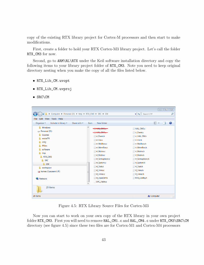
copy of the existing RTX library project for Cortex-M processors and then start to makemodifications.
First, create a folder to hold your RTX Cortex-M3 library project. Let’s call the folderRTX_CM3 for now.
Second, go to ARM\RL\RTX under the Keil software installation directory and copy thefollowing items to your library project folder of RTX_CM3. Note you need to keep originaldirectory nesting when you make the copy of all the files listed below.
• RTX_Lib_CM.uvopt
• RTX_Lib_CM.uvproj
• SRC\CM
Figure 4.5: RTX Library Source Files for Cortex-M3
Now you can start to work on your own copy of the RTX library in your own projectfolder RTX_CM3. First you will need to remove HAL_CM1.c and HAL_CM4.c under RTX_CM3\SRC\CMdirectory (see figure 4.5) since these two files are for Cortex-M1 and Cortex-M4 processors
43

Figure 4.6: RTX Library Project Components for Cortex-M3
which is not the hardware in the lab. Notice that we have preserved the file directorystructure of the original RTX library project provided by ARM.
Open RTX_Lib_CM.uvproj under your RTX_CM3 directory that you newly created. Rightclick the CM1_LE target under the project window to bring up the menu and click “Man-age Components”. You will only need the CM3_LE target, which supports NXP1768 onMCB1700 boards. Remove all other targets in the Project Targets window. You also needto remove the HAL_CM1.c and HAL_CM4.c files in the Files window (see Figure 4.6). Clickthe Build button to build the library. You will notice a .lib file is created under CM3_LE
folder and this is the RTX library for Cortex-M3 processor you just built.
4.3 Creating an RTX Application with a Self-built
RTX Library
You have just successfully re-built an RTX library. This library has no difference than thestocked RTX Library provided by ARM. In lab projects, you will be asked to add more
44

functions to the RTX Library. This means you need to modify the source code of the RTXlibrary.
The default RTL.h file is the RTX user interface. When new RTX API functions areadded to the RTX, the corresponding user level interface of the function needs to be addedto this file. So we need to further put a modified RTL.h file somewhere in the project. Agood place would be in the directory where the RTX_CM3 library project is resided. Let’screate a folder and name it INC. Inside this folder, copy the default ARM\RV31\INC\RTL.hin the Keil software installation directory to the newly created RTX_CM3\INC\ directory.
The RTX library you just build cannot be executed because it is only a library file.You will need to create an RTX Application which calls some of the functions inside theRTX library file in order to see the effect of the library you built. We can copy the entireRTX HelloWorld application directory (see Section 4.1) to the parent directory of RTX_CM3first.
Figure 4.7: Keil IDE: Create New Multi-Project Worksapce
There are two projects we want to manage at the same time. The first one is our ownversion of RTX library and the other one is this RTX HelloWorld RTX application. We cancreate a new multi-project workspace to hold two projects. Click Project → New Multi-Project Workspace (see Figure 4.7). A new window appears to ask you to pick a name forthe multi-project workspace and let’s call it helloworld_rtxlib.uvmpw (see Figure 4.8).
A new window will pop up to ask you add µVision projects into the workspace. Clickthe New button to start adding a project and click the Browse button to select a projectfile (see Figure 4.9). Let’s first add the RTX_CM_Lib.uvproj (see Figure 4.10). Similarly,add RTX_HelloWorld.uvproj to the workspace (see Figure 4.11). Finally click the OKbutton to finish adding projects into the workspace.
Two projects appear under the Project Window (see Figure 4.12. Click the Batch Buildbutton (see Figure 4.12 to bring up the Batch Build window. Select all the targets you
45

Figure 4.8: Keil IDE: Naming a New Multi-Project Worksapce
Figure 4.9: Keil IDE: Adding a µVision Project into Worksapce
want to build in a batch (see Figure 4.13). By setting up batch build, multiple targets canbe built by a single click of the build button. Whenever you make a change in the RTXLibrary project, you need to rebuild the library and the application that uses the library.So batch build will make multiple builds easy to carry out.
Having finished the workspace setup, we can start to modify the RTX HelloWorldapplication so that it links with the RTX Library we build instead of the stocked RTXprovided by ARM. To do this you first need to activate the RTX_HelloWorld project byhighlighting the project name and right click and then click the Set as Active Project (seeFigure 4.14).
We want to remove the stocked RTX library from the target option setting (see Figure4.15). Then we add the RTX library we build (i.e. RTX_CM3.lib) to the project (seeFigure 4.16). Finally we need to change the source code of helloworld.c to include ourown version of RTL.h instead of the default one (see Figure 4.17).
46

Figure 4.10: Keil IDE: Adding RTX CM Lib.uvproj into Worksapce
Figure 4.11: Keil IDE: Adding RTX HelloWorld.uvproj into Worksapce
47

Figure 4.12: Keil IDE: Workspace with Two Projects
Figure 4.13: Keil IDE: Batch Build
48

Figure 4.14: Keil IDE: Set an Active Project
Figure 4.15: Keil IDE: Removing Linkage with Stocked RTX Library
Figure 4.16: Keil IDE: Adding a Your Own RTX Library
49

Figure 4.17: Keil IDE: Including Your Own RTL.h
50

Chapter 5
Programming MCB1700
5.1 The Thumb-2 Instruction Set Architecture
The Cortex-M3 supports only the Thumb-2 (and traditional Thumb) instruction set. Withsupport for both 16-bit and 32-bit instructions in the Thumb-2 instruction set, there is noneed to switch the processor between Thumb state (16-bit instructions) and ARM state(32-bit instructions).
In the RTOS lab, you will need to program a little bit in the assembler language. Weintroduce a few assembly instructions that you most likely need to use in your project inthis section.
The general formatting of the assembler code is as follows:
label
opcode operand1, operand2, . . . ; Comments
The label is optional. Normally the first operand is the destination of the operation (noteSTR is one exception).
Table 5.1 lists some assembly instructions that the RTX project may use. For completeinstruction set reference, we refer the reader to Section 34.2 (ARM Cortex-M3 User Guide:Instruction Set) in [4].
5.2 ARM Architecture Procedure Call Standard (AAPCS)
The AAPCS (ARM Architecture Procedure Call Standard) defines how subroutines can beseparately written, separately compiled, and separately assembled to work together. The
51

Mnemonic Operands/Examples DescriptionLDR Rt , [Rn,#offset ] Load Register with word
LDR R1, [R0,#24] Load word value from an memory address R0+24 into R1LDM Rn{!}, reglist Load Multiple registers
LDM R4, {R0− R1} Load word value from memory address R4 to R0, increment theaddress, load the value from the updated address to R1.
STR Rt , [Rn,#offset ] Store Register wordSTR R3, [R2, R6] Store word in R3 to memory address R2+R6STR R1, [SP,#20] Store word in R1 to memory address SP+20
MRS Rd , spec reg Move from special register to general registerMRS R0, MSP Read MSP into R0MRS R0, PSP Read PSP into R0
MSR spec reg ,Rm Move from general register to special registerMSR MSP, R0 Write R0 to MSPMSR PSP, R0 Write R0 to PSP
PUSH reglist Push registers onto stackPUSH {R4− R11, LR} push in order of decreasing the register numbers
POP reglist Pop registers from stackPOP {R4− R11, PC} pop in order of increasing the register numbers
BL label Branch with LinkBL funC Branch to address labeled by funC, return address stored in LR
BLX Rm Branch indirect with linkBLX R12 Branch with link and exchange (Call) to an address stored in R12
BX Rm Branch indirectBX LR Branch to address in LR, normally for function call return
Table 5.1: Assembler instruction examples
52

C compiler follows the AAPCS to generate the assembly code. Table 5.2 lists registersused by the AAPCS.
Register Synonym Special Role in the procedure call standardr15 PC The Program Counter.r14 LR The Link Register.r13 SP The Stack Pointer (full descending stack).r12 IP The Intra-Procedure-call scratch register.r11 v8 Variable-register 8.r10 v7 Variable-register 7.r9 v6 Platform register.
SB The meaning of this register is defined by platform standard.TR
r8 v5 Variable-register 5.r7 v4 Variable-register 4.r6 v3 Variable-register 3.r5 v2 Variable-register 2.r4 v1 Variable-register 1.r3 a4 argument / scratch register 4r2 a3 argument / scratch register 3r1 a2 argument / result / scratch register 2r0 a1 argument / result / scratch register 1
Table 5.2: Core Registers and AAPCS Usage
Registers R0-R3 are used to pass parameters to a function and they are not preserved.The compiler does not generate assembler code to preserve the values of these registers.R0 is also used for return value of a function.
Registers R4-R11 are preserved by the called function. If the compiler generated as-sembler code uses registers in R4-R11, then the compiler generate assembler code to auto-matically push/pop the used registers in R4-R11 upon entering and exiting the function.
R12-R15 are special purpose registers. A function that has the svc indirect keywordmakes the compiler put the first parameter in the function to R12 followed by an SVC
instruction. R13 is the stack pointer (SP). R14 is the link register (LR), which normallyis used to save the return address of a function. R15 is the program counter (PC).
Note that the exception stack frame automatically backs up R0-R3, R12, LR andPC together with the xPSR. This allows the possibility of writing the exception handler inpurely C language without the need of having a small piece of assembly code to save/restoreR0-R3, LR and PC upon entering/exiting an exception handler routine.
53

5.3 Cortex Microcontroller Software Interface Stan-
dard (CMSIS)
The Cortex Microcontroller Software Interface Standard (CMSIS) was developed by ARM.It provides a standardized access interface for embedded software products (see Figure 5.1).This improves software portability and re-usability. It enables software solution suppliersto develop products that can work seamlessly with device libraries from various siliconvendors [2].
Figure 5.1: Role of CMSIS[8]
The CMSIS uses standardized methods to organize header files that makes it easy tolearn new Cortex-M microcontroller products and improve software portability. With the<device>.h (e.g. LPC17xx.h) and system startup code files (e.g., startup_LPC17xx.s),your program has a common way to access
• Cortex-M processor core registers with standardized definitions for NVIC, Sy-sTick, MPU registers, System Control Block registers , and their core access functions(see core cm ∗ .[ch] files).
• system exceptions with standardized exception number and handler names toallow RTOS and middleware components to utilize system exceptions without havingcompatibility issues.
• intrinsic functions with standardized name to produce instructions that cannotbe generated by IEC/ISO C.
• system initialization by common methods for each MCU. Fore example, the stan-dardized SystemInit() function to configure clock.
• system clock frequency with standardized variable named as SystemFrequency
defined in the device driver.
54

• vendor peripherals with standardized C structure.
Figure 5.2: CMSIS Organization[2]
5.3.1 CMSIS files
The CMSIS is divided into multiple layers (See Figure 5.2). For each device, the MCUvendor provides a device header file <device>.h (e.g., LPC17xx.h) which pulls in additionalheader files required by the device driver library and the Core Peripheral Access Layer (seeFigure 5.3).
By including the <device>.h (e.g., LPC17xx.h) file into your code file. The first stepto initialize the system can be done by calling the CMSIS function as shown in Listing 5.1.
SystemInit(); // Initialize the MCU clock
Listing 5.1: CMSIS SystemInit()
The CMSIS compliant device drivers also contain a startup code (e.g., startup_LPC17xx.s),which include the vector table with standardized exception handler names (See Section5.3.3.
5.3.2 Cortex-M Core Peripherals
We only introduce the NVIC programming in this section. The Nested Vectored InterruptController (NVIC) can be accessed by using CMSIS functions (see Figure 5.4). As an
55

Figure 5.3: CMSIS Organization[2]
Figure 5.4: CMSIS NVIC Functions[2]
example, the following code enables the UART0 and TIMER0 interrupt
NVIC_EnableIRQ(UART0_IRQn); // UART0_IRQn is defined in LPC17xx.h
NVIC_EnableIRQ(TIMER0_IRQn); // TIMER0_IRQn is defined in LPC17xx.h
56

5.3.3 System Exceptions
Writing an exception handler becomes very easy. One just defines a function that takesno input parameter and returns void. The function takes the name of the standardizedexception handler name as defined in the startup code (e.g., startup_LPC17xx.s). Thefollowing listing shows an example to write the UART0 interrupt handler entirely in C.
void UART0_Handler (void)
{
// write your IRQ here
}
Another way is to use the embedded assembly code:
__asm void UART0_Handler(void)
{
; do some asm instructions here
BL __cpp(a_c_function) ; a_c_function is a regular C function
; do some asm instructions here,
}
5.3.4 Intrinsic Functions
ANSI cannot directly access some Cortex-M3 instructions. The CMSIS provides intrinsicfunctions that can generate these instructions. The CMSIS also provides a number offunctions for accessing the special registers using MRS and MSR instructions. The intrinsicfunctions are provided by the RealView Compiler. Table 5.3 lists some intrinsic functionsthat your RTOS project most likely will need to use. We refer the reader to Tables 613and 614 one page 650 in Section 34.2.2 of [4] for the complete list of intrinsic functions.
5.3.5 Vendor Peripherals
All vendor peripherals are organized as C structure in the <device>.h file (e.g., LPC17xx.h).For example, to read a character received in the RBR of UART0, we can use the followingcode.
unsigned char ch;
ch = LPC_UART0->RBR; // read UART0 RBR and save it in ch
57

Instruction CMSIS Intrinsic FunctionCPSIE I void enable irq(void)CPSID I void disable irq(void)
Special Register Access CMSIS FunctionCONTROL Read uinit32 t get CONTROL(void)
Write void set CONTROL(uint32 t value)MSP Read uinit32 t get MSP(void)
Write void set MSP(uint32 t value)PSP Read uinit32 t get PSP(void)
Write void set PSP(uint32 t value)
Table 5.3: CMSIS intrinsic functions defined in core cmFunc.h
5.4 Accessing C Symbols from Assembly
Only embedded assembly is support in Cortex-M3 (i.e. inline assembly is not supported).To write an embedded assembly function, you need to use the asm keyword. For exam-ple the the function “embedded asm function” in Listing 5.2 is an embedded assemblyfunction. You can only put assembly instructions inside this function. Note that inlineassembly is not supported in Cortex-M3.
The cpp keyword allows one to access C compile-time constant expressions, includingthe addresses of data or functions with external linkage, from the assembly code. Theexpression inside the cpp can be one of the followings:
• A global variable defined in C
typedef struct pcb {
struct * mp_next;
uint32_t m_sp;
//.....
} pcb_t;
pcb_t g_pcb;
uint32_t g_var;
__asm embedded_asm_function(void) {
LDR R3, =__cpp(&g_pcb) ; load R3 with the address of g_pcb
LDM R3, {R1, R2} ; load R1 with g_pcb.mp_next
; load R2 with g_pcb.m_sp
LDR R4, =__cpp(g_var) ; load R4 with the value of g_var
58

}
Listing 5.2: Example of accessing global variable from assembly
• A C function
extern void a_c_function(void);
...
__asm embedded_asm_function(void) {
;......
BL __cpp(a_c_function) ; a_c_function is regular C function
;......
}
• A constant expression in the range of 0− 255 defined in C.
uint8_t const g_flag;
__asm embedded_asm_function(void) {
;......
MOV R4, #_cpp(g_flag) ; load g_flag value to R4
;......
}
Note the MOV instruction only applies to immediate constant value in the range of0− 255.
You can also use the IMPORT directive to import a C symbol in the embedded assemblyfunction and then start to use the imported symbol just as a regular assembly symbol. Forexample
void a_c_function (void) {
// do something
}
__asm embedded_asm_add(void) {
IMPORT a_c_function ; a_c_function is a regular C function
BL a_c_function ; branch with link to a_c_function
}
59

Names in the __cpp expression are looked up in the C context of the __asm function.Any names in the result of the __cpp expression are mangled as required and automaticallyhave IMPORT statements generated from them.
5.5 SVC Programming: Adding a Function to RTX
API
Figure 5.5: SVC as a Gateway for OS Functions [8]
A function in RTX API requires a service from the operating system. It needs to beimplemented through the proper gateway by trapping from the user level into the kernellevel. On Cortex-M3, the SVC instruction is used to achieve this purpose.
The basic idea is that when a function in RTX API is called from the user level,this function will trigger an SVC instruction. The SVC_Handler, which is the CMSISstandardized exception handler for SVC exception will then invoke the a kernel functionthat provide the actual service (see Figure 5.5). Effectively, the RTX API function isa wrapper that invokes SVC exception handler and passes corresponding kernel serviceoperation information to the SVC handler.
To generate an SVC instruction, there are two methods. One is a direct method andthe other one is an indirect method.
The direct method is to program at assembly instruction level. We can use the embed-ded assembly mechanism and write SVC assembly instruction inside the embedded assemblyfunction. The ARM RL-RTX API functions that are not started with the os_ prefix areimplemented in this way. Examples are _alloc_box and _free_box defined in HAL_CM3.c.Listing 5.3 shows the code snippet of the _alloc_box.
__asm void *_alloc_box(void *box_mem) {
LDR R12,=__cpp(rt_alloc_box)
60

; privileged mode code handling omitted for brevity reason
SVC 0
BX LR
ALIGN
}
Listing 5.3: Code Snippet of alloc box
The corresponding kernel function is the C function rt_alloc_box defined in rt_MemBox.c.This function entry point is loaded to r12. Then SVC 0 causes an SVC exception withimmediate number 0. In the SVC exception handler, we can then branch with link andexchange to the address stored in r12. Listing 5.4 is an excerpt of the SVC_handler inHAL_CM3.c from the ARM RL-RTX source code.
__asm void SVC_Handler(void) {
MRS R0, PSP
;Extract SVC number, if SVC 0, then do the following
LDM R0, {R0-R3, R12}; Read R0-R3, R12 from stack
BLX R12 ; R12 contains the kernel function entry point
;Code to handle context switching is omitted
MVN LR, #:NOT:0xFFFFFFFD; set EXC_RETURN, thread mode, PSP
BX LR ;
;User SVC code is omitted
}
Listing 5.4: Code Snippet of SVC Handler
The indirect method is to ask the compiler to generate the SVC instruction from C code.The ARM compiler provides an intrinsic keyword named __svc_indirect which passesan operation code to the SVC handler in r12[3]. This keyword is a function qualifier. Thetwo input we need to provide to the compiler is
• svc_num, the immediate value used in the SVC instruction and
• op_num, the value passed in r12 to the handler to determine the function to perform.The following is the syntax of an indirect SVC.
61

__svc_indirect(int svc_num)
return_type function_name(int op_num[, argument-list]);
The system handler must make use of the r12 value to select the required operation. Forexample The RL-RTX provide the following user level function to terminate a task:
#include <rtl.h>
OS_RESULT os_tsk_delete (OS_TID taskid)
In RTL.h, the following code is revelent to the implementation of the function.
#define __SVC_0 __svc_indirect(0)
extern OS_RESULT rt_tsk_delete(OS_TID task_id);
#define os_tsk_delete(task id) _os_task_delete ((U32) rt_tsk_delete,
task_id)
extern OS_RESULT _os_tsk_delete (U32 p, OS_TID task_id) __SVC_0;
The compiler generates two assembly instructions
LDR.W r12, [pc, #offset]; Load rt_tsk_delete in r12
SVC 0x00
The SVC_handler in Listing 5.4 then can be used to handle the SVC 0 exception.
62
Part II
Laboratory Projects
63

Chapter 6
Lab Administration Policy
6.1 Group Lab Policy
• Group Size: All labs are done in a group of two members. A size of three is onlyconsidered in a lab section that has an odd number of students and only one groupis allowed to have a size of three. All group of three requests are processed on afirst-come first-served basis. A group size of one is not permitted except that yourgroup is split up. There is no workload reduction if you do the labs individually. TheCourse Book System at URLhttps://ecewo32.uwaterloo.ca/cgi-bin/WebObjects/CourseBook
is used to signup for groups and reserve lab demo times. The lab group signup is dueby 4:30pm on the First Friday of the academic term. Late group sign-up incurs a 5%per day final lab mark deduction.
• Group Split-up: Teamwork is an important skill that will benefit you in yourfuture career. Please work together and take on your fair share of the workload. Inan extreme case where you and your partner are unable to work together, you areallowed to split only once during the term. You can find a new lab partner (if thereis one available from another split-up group) after the split. But you are not allowedto split from the newly formed group any more. Please choose your lab partnercarefully. A copy of the code or documentation done before the group split-up willbe given to each individual in the group.
• Group Split-up Deadline: To split from your group for a particular lab, you needto notify the lab instructor in writing and sign the group slip-up form (available onthe Lab website). Labn (n=1,2,3,4) group split-up form needs to be submitted tothe lab instructor during the week that Labn has scheduled lab sessions. If you arelate to submit the split-up form, then you need to finish Labn as a group and submit
64

your split-up form during the week where Lab(n+1) has scheduled sessions and splitstarting from Lab(n+1).
6.2 Lab Assignments Deadline Policy.
• Lab Assignment Preparation and Due Dates: Students are required to preparethe lab well before they come to the schedule lab session. Pre-lab deliverable for eachlab is due before the lab starts. During the scheduled lab session, we either providein lab help or conduct lab assignment evaluation or do both at the same time. ThePost-lab deliverable is due 10:00pm on Wednesday in the week before the schedulednext lab session. Please be advised that lab sessions during the midterm week arecanceled.
• Lab Assignment Late Submissions: There are five grace days that can be usedfor some Post-lab deliverables late submissions. A Post-lab deliverable that doesnot accept a late submission will be clearly stated in the lab assignment description.Normally grace days are for lab reports. Labs whose evaluation involves demos donot accept late submissions of the code. A group split-up will consume one grace day.When you use up all your grace days, a 10% per day late penalty will be applied to alate submission. Please be advised that to simplify the book-keeping, late submissionis counted in a unit of day rather than hour or minute. An hour late submission isone day late, so does a fifteen hour late submission.
6.3 Lab Grading Policy
Labs are graded by lab TAs based on the rubric listed in each lab. The weight of each labtowards your final course grade is listed in Table 6.1. Lab4 is not required if componentweights 30% of the course grade.
6.4 Lab Facility After Hour Access Policy
After hour access to the lab will be given to the class when we start to use the Keil boardsin lab. However please be advised that the after hour access is a privilege. Studentsare required to keep the lab equipment and furniture in good conditions to maintain thisprivilege.
65

Title Weight
Lab0-A 2%Lab0-B 2%Lab1 9%Lab2 7%Lab3 10%Lab4 10%
Table 6.1: Lab Weight
No food or drink is allowed in the lab (water is permitted). Please be informed that youmay share the lab with other classes. When resources become too tight, certain cooperationis required such as taking turns to use the stations in the lab.
66

Chapter 7
Lab0-A: Introduction to LinuxSystem Programming
7.1 Objective
This lab is to introduce the general Linux Development Environment at ECE departmentand basic Linux system programming procedures to students. After finishing this lab,students will have a good understanding of the following:
• How to use the gcc compiler on Linux.
• How to use the make utility on Linux.
• How to use the ddd debugger on Linux.
• How to read Linux manual page.
• How to write a C program to obtain file attributes.
7.2 Starter Files
Download the lab0_linux.zip file from Learn. It contains the following:
• Getting system resource limit example code
• Listing names of all file in a directory and type of a file example code
67

7.3 Pre-lab Preparation
Read Chapter 1.
7.4 Warm-up Exercises
This exercise is to practice a few basic UNIX commands for developing a C program onLinux.
1. Use the SSH Secure Shell Client to login onto ecelinux.uwaterloo.ca. You arenow inside the Linux shell.
2. Use the ls command to list all files in your current working directory.
3. Read the online manual of the ls command by issuing man ls command to the shell.
• Which option of ls produces output in long listing format, which includes the filetype, permission, ownership, group ownership, size, time of the last modificationand file name?
• What does -a option do?
4. Create a directory as the work space of ECE254/MTE241 labs. Name the newlycreated directory as ece254 or “mte241. Read the man page of the command mkdir
to see how to do it.
5. Change directory to the newly create directory of ece254 or mte241. The commandis cd. Read the man page to find out the exact syntax of the command.
6. Create a lab0 sub-directory and change current directory to it.
7. Download the lab0_example.zip file from the lab web site. Save the file in theece254/lab0 or mte241/lab0 directory.
8. Unzip the file by using the unzip command.
9. Modify main.c file in the rlimit directory so that it will print out the stack sizelimit.
68

7.5 Lab0-A Assignment
This assignment is to program a simple ls command. Write a program in C to list thefollowing attributes of all files in the $HOME/ece254/lab0 directory you created in Section7.4
1. File name, mode (type and permissions for user, group and other) and size
2. File access time, last modify time and last status change time
3. File ownership and group ownership
Hints
• From the OS point of view, a directory is a file. But it is a special file. Read theman page of opendir(), readdir(), closedir(). Can open()/close() systemcall open/close a directory? Can you read a directory file by the read() systemcall? Read the man page of perror(), which prints a system error message.Use perror() to print out system error when a call fails is a good programmingpractice.
• The stat(), fstat() and lstat() system calls can be used to obtain file at-tribute information. Read the man page (section 2) of these system calls. Whichone of these system calls gives information about a symbolic link file?
• Execute the Linux “ls -alt” and “stat <filename>” commands and see theoutput.
• Study ls_fname.c, ls_ftype.c and ls_fperm.c files in the lab0_linux.zip.The example files show how command line arguments are passed to the main
function and how to interpret the st_mode value in the system defined struct stat
by using system defined macros.
• Study the man pages of strcmp(), strcat(), strlen(), getpwuid(), getgrgid()and ctime().
7.6 Deliverables
7.6.1 Pre-lab Deliverables
There is no pre-lab deliverable.
69

7.6.2 Post-lab Deliverables
Your Lab assignment (see Section 7.5) source code, Makefile and a README (includingbuild instruction) in a singled compressed archive and name it lab0A_linux.ext, whereext can be zip, gz or Z. Submit to the Course Book System.
7.7 Marking Rubric
TA will test your source code on one of the ecelinux machines. Total mark is 10. Youwill get full mark is all required file attributes are displayed correctly. Partial mark willbe given based on the portion of the correctly displayed file attributes if not all requiredattributes are displayed correctly.
70
Chapter 8
Lab0-B: Introduction to ARMRL-RTX Kernel and ApplicationProgramming
8.1 Objective
This Lab is to introduce the Keil µVision4 IDE and ARM RL-RTX development. Stu-dents will build the ARM RL-RTX from source. After this lab, students will have a goodunderstanding of the following:
• How to create a µVision RTX project;
• How to build an RL-RTX library from source;
• How to create an application with self-built RTX Library;
• How to use SVC as the gateway to program OS functions.
8.2 Starter Files
Download the lab0_keil.zip file from Learn. It contains the following:
• A µVision project that prints “Hello World!” to UART0.
71

8.3 Pre-lab Preparation
• Read Chapters 2 and 3 and Section 5.5.
• Read the reference manual of memory management functions in RL-RTX help files(see 4.4). Familiarize yourself with the procedure of how to declare a memory pool,allocate a fixed size memory block and free a memory block
8.4 Warm-up Exercises
8.4.1 Download the HelloWorld to the Board
This warm-up exercise is to get you familiar with the UART simulator and RAM targetdownloading and execution.
• Run the HelloWorld project under simulator and watch the output in UART#1window.
• Download the HelloWorld RAM target to the board by entering the debug session.Step through the code and watch the output through a putty session.
8.4.2 Creating an RL-RTX Application
Follow the steps in Section 4.1 to create and run the example HelloWorld RTX applicationinside simulator and on the board.
Notes
• The Keil IDE does not tolerate space(s) in the path name on Nexus. For example,a project in a directory which contains My Documents as part of the path namesometimes will give you error saying certain files could not be created.
• Do remember to configure the CPU speed to 100 MHZ through the RTX_Conf_CM.c
configuration wizard. Otherwise you will get wrong timing result.
• The default stack size is 200 bytes. Using printf family functions such as sprintf
can easily cause a stack overflow. You will encounter Hard Fault exception. Stack sizecan be configured through the configuration wizard in RTX_Conf_CM.c file. Normally512B would be sufficient. If you are not tight on memory, 1 KB is safer.
72

8.4.3 A HelloWorld Application Linked with Your Own RTX
Follow the steps in Sections 4.2 and 4.3 to build a multi-project workspace that containsa HelloWorld RTX application that links with a self-built RTX library.
Build and download the HelloWorld application. Verify it works both under simulatorand on the board.
8.5 Lab0-B Assignment
8.5.1 Questions
1. The RTX_Config.h has a list of variables externally defined in RTX_lib.c file, whichis located at ARM\RV31\INC under the default Keil installation directory. What doesos_active_TCB array contain?
2. Is the os_idle_daemon an element in the os_active_TCB?
3. For a task with task ID n, what is the index of this task’s TCB in the arrayos_active_TCB?
8.5.2 Programming Project
1. Add a function to RL-RTX API to return the number of active tasks in the system.A task is considered active when its state is not set to INACTIVE in the TCB.
int os_tsk_count_get (void);
Note that you need to use the SVC as the gateway to access the kernel data structure.
2. Write five simple tasks. One of the tasks calls the os_tsk_count_get function totest the number of active tasks in the system returned by the function.
8.6 Deliverables
8.6.1 Pre-lab Deliverables
There is no pre-lab deliverable.
73

Points Description3 Answers to Pre-lab questions2 Building a multi-project workspace that contains
self-built RTX and an application that links withthis RTX
3 Implementation of os_tsk_count_get2 Implementation of testing tasks to test
os_tsk_count_get
Table 8.1: Lab0-B Marking Rubric
8.6.2 Post-lab Deliverables
Submit a compressed archive file that contains the following:
1. Answers to questions in Section 8.5.1.
2. Source code and and a README (any useful instructions for evaluation TA) of theprogramming project in Section 8.5.2.
Name the file lab0B_keil.ext, where ext can be zip, gz or Z, and submit it to theCourse Book System.
8.7 Marking Rubric
Table 8.1 shows the rubric for marking the lab.
74

Chapter 9
Lab1: Task Management in RL-RTX
9.1 Objective
This lab is to learn about, and gain practical experience in ARM RL-RTX kernel program-ming. In particular, you will add three functions to ARM RL-RTX library.
After this lab, students will have a good understanding of:
• how to program an RTX function to read kernel task control block related datastructure;
• how to block and unblock a task by using context switching related kernel functions.
9.2 Starter files
• Your Lab0-B source code;
• A sample main.c that calls os_tsk_get.
9.3 Pre-lab Preparation
1. Read the rt_TypeDef.h file and answer the following questions.
• What are the purpose of p_lnk, p_rlnk, p_dlnk, and p_blnk variables instruct OS_TCB?
75

• What is the purpose of ret_val in struct OS_TCB?
2. Read the rt_Task.c and RTX_lib.c files and answer the following question.
• What is the purpose of variables mp_tcb and mp_stack?
3. Read the HAL_CM3.c file and answer the following questions.
• What registers are saved on the task stack? (Hint: check init_stack function)
• How to determine the start and end address of a task stack?
• How to determine the current stack pointer of a task?
4. Read the rt_Mailbox.c file and answer the following questions.
• When a task is blocked with WAIT_MBX state, it will be resumed once a messageappears in the mailbox (assuming timeout value is set to 0xFFFF). What is thereturn code of os_mbx_wait() after the task is resumed?
• Inside the rt_mbx_wait() function, there are three return statements. The firstone returns OS_R_OK. The last two return OS_R_TMO. Does this mean the answerto the question above is either OS_R_OK or OS_R_TMO? Why or why not?
5. The os_dly appears in multiple kernel files. It is an ordered list. What is the purposeof variable os_dly? What criteria are used to order the items in this list? Can youuse os_dly list to enqueue TCBs that are waiting for memory blocks in Part B? Whyor why not?
9.4 Lab1 Assignment
There are two parts of this assignment. They are Part A and Part B.
9.4.1 Part A
To get familiar with kernel source code, a good start is to write a function to retrievea kernel data structure. In this assignment, you are to implement a primitive to obtainthe task status information from the RTX at runtime given the task id. The functiondescription is as follows.
• OS_RESULT os_tsk_get (OS_TID task_id, RL_TASK_INFO *buffer)
76

The primitive returns information about a task. The system call returns a rl_task_infostructure , which contains the following fields:
typedef struct rl_task_info {
U8 state; /* Task state */
U8 prio; /* Execution priority */
U8 task_id; /* Task ID value for optimized TCB access */
U8 stack_usage; /* Stack usage percent value. eg.=58 if 58% */
void (*ptask)(); /* Task entry address */
} RL_TASK_INFO;
The state field describes the state of this task and is one of:
INACTIVE
Tasks which have not been started or tasks which have been deleted are inINACTIVE state.
READY
Tasks which are ready to run are in the READY state.
RUNNING
The task that is currently running is in the RUNNING state. Only one task at atime can be in this state.
WAIT_DLY
Tasks which are waiting for a delay to expire are in the WAIT_DLY state. Thetask is switched to the READY state once the delay has expired.
WAIT_SEM
Tasks which are waiting for a semaphore are in the WAIT_SEM state. When thetoken is obtained from the semaphore, the task is switched to the READY state.
WAIT_MUT
Tasks which are waiting for a free mutex are in the WAIT_MUT state. When amutex is released, the task acquires the mutex and switches to the READY state.
WAIT_MBX
77

Tasks which are waiting for a mailbox message are in the WAIT_MBX state. Oncethe message has arrived, the task is switched to the READY state. Tasks waitingto send a message when the mailbox is full are also put into the WAIT_MBX state.When the message is read out from the mailbox, the task is switched to theREADY state.
WAIT_MEM
Tasks which are waiting for memory are in the WAIT_MEM state. Once the mem-ory is available, the task is switched to READY state. The os_mem_alloc()
function is used to place a task in WAIT_MEM state.
These states are described in details in the RL-ARM Real-Time Library User’sGuide → Theory of Operation→ Task Management section except for WAIT_MEM
state. Read Lab3 Assignment Part B regarding how tasks are blocked upon callingos_mem_alloc() function.
The prio field describes the priority of this task.
The task_id field describes the id of task assigned by the OS.
The stack_usage describes how much stack space is used by this task. The value isthe percent value. For example, if 58% of this task stack is used, stack_usage is setto 58.
The ptask field describes the entry address of this task function.
The function returns OS_R_OK on success and OS_R_NOK otherwise.
9.4.2 Part B
You are to write two memory management RTX functions to manage a memory pool fortasks. The function descriptions are as follows.
• void *os_mem_alloc (void *box_mem)
The primitive allocates a fixed-size of memory to the calling task from the memorypool pointed by box_mem and returns a pointer to the allocated memory. When thereis not enough memory available, the calling task is blocked until enough memorybecomes available. If several tasks are waiting for memory and memory becomesavailable, the highest priority waiting task will get the memory. Within the samepriority waiting tasks, the one that waits longest will get the memory.
78

• OS_RESULT os_mem_free (void *box_mem, void *box)
The primitive returns a memory block whose address is box to memory pool withstarting address of box_mem. Note the box is allocated by os_mem_alloc from themeory pool of box_mem. It returns OS_R_OK on success and OS_R_NOK otherwise.If several tasks are waiting for memory and memory becomes available, the highestpriority waiting task will get the memory and be unblocked. Preemption may happenif the unblocked task has higher priority than the task that calls this function to freeup the memory.
Create a set of testing tasks to demonstrate that you have successfully implementedthe required functions in Parts A and B. Your test tasks should do the following tests.
• A task periodically prints task status of each task in the system.
• A task can allocate a fixed size of memory.
• A task will get blocked if there is no memory available when os_mem_alloc() iscalled.
• A blocked on memory task will be resumed once enough memory is available in thesystem.
• Create a testing scenario that multiple tasks with different priorities are all blockedwaiting for memory. When memory becomes available, test whether it is the highestpriority task that waits the longest that gets the memory first.
9.5 Deliverables
9.5.1 Pre-Lab Deliverables
Submit your answers to Pre-lab questions (see Section 9.3) to the Course Book System.Name your file lab1_pre.ext, where ext can be pdf, docx or txt.
9.5.2 Post-Lab Deliverables
Create a compressed archive with name lab1.ext, where ext can be zip, gz or Z. The fileis required to contain the following item(s).
79

Points Sub-total Description
20 Answers to pre-lab questions30 Part A Implementation
15 os_tsk_get function implementation10 self-implemented testing cases to test Part A API
function5 Third-party testing case result
50 Part B Implementation20 os_mem_alloc and os_mem_free implementation20 self-implemented testing cases to test the correct-
ness of Part B API functions10 Third-party testing case result
Table 9.1: Lab1 Marking Rubric
• A README file to describe what you have submitted and how to build and run yourproject(s).
• Your source code to solve lab1 assignment. For example the entire µVision multi-project workspace folder.
• A test description file to describe what each testing task does. Name the file lab1_test_spec.ext,where ext can be pdf, docx or txt.
Submit the file to the course book system before the deadline. Unless you notify the labTAs and the lab instructor by email, we will mark the latest submission when there aremultiple submissions presented.
9.6 Marking Rubric
Table 9.1 shows the marking rubric for this lab.
80

Chapter 10
Lab2: Inter-process Communicationby Message Passing
10.1 Objective
This lab is to learn about, and gain practical experience in message passing for the purposeof inter-process communication. In particular, you will use the POSIX message queuefacility in a general Linux environment and the mailbox APIs in RL-RTX on the KeilLPC1768 board.
After this lab, students will have a good understanding of, and ability to program with
• the fork() and exec() system calls, and their use for creating a new child processon the Linux platform;
• the wait() family system calls, and their use to obtain the status-change informationof a child process;
• the POSIX message queue facility (<mqueue.h>) on the Linux platform for inter-process communication; and
• the use of mailbox APIs in RL-RTX for inter-task communication.
10.2 Starter files
Download the lab2_example.zip file from the lab website. It contains the following:
81
• Linux child-process example code [6],
• Linux POSIX message queue API example code, and
• LPC1768 frequently used example code.
10.3 Pre-lab Preparation
1. Read Section 3.2.2 about fork() and exec() and Sections 3.4.1 and 3.4.2 aboutwait() in [6].
2. Complete the example code of wait() on page 57 in [6] by including necessary headerfiles and compile it. Execute it to examine the difference of the output from theoutput of the code in Listing 3.4.
3. Read the man page (section 7) of mq_overview(http://linux.die.net/man/7/mq_overview).
4. Build and execute the example code in the mqueue sub-directory in the lab2_example.zipfile, and
5. Read the Keil µVision4 IDE getting started guide (posted on the lab web site).Install the MDK-ARM on your own personal computer.
10.4 Lab2 Assignment
Solve the producer-consumer problem by message passing both on Linux and on the KeilLPC 1768 board.
This is a classic multi-tasking problem in which there are one or more tasks that createdata (these tasks are referred to as “producers”) and one or more tasks that use the data(these tasks are referred to as “consumers”). For the purpose of this assignment, we willuse a single producer and single consumer. The producer will generate a fixed number, N,of random integers, one at a time. Each time a new integer is created, it is sent to theconsumer using the system message-passing facility (POSIX queues for Linux, mailboxesfor Keil). The consumer task receives the the data using the system’s message-passingfacility, and prints out the integer it has read1.
1If it helps, you can think of the producer as a keyboard device driver and the consumer as theapplication wishing to read keystrokes from the keyboard; in such a scenario the person typing at thekeyboard may enter more data than the consuming program wants, or conversely, the consuming programmay have to wait for the person to type in characters. This is, however, only one of many cases whereproducer/consumer scenarios occur, so do not get too tied to this particular usage scenario.
82

Note that because we are using message passing, the two processes will not share anymemory. Consequently, we do not need to worry about conflicting operations in shared-memory access: the operating system’s message-passing facility takes care of the sharedaccess within kernel space. However, kernel memory is finite, and thus there cannot bean unbounded number of messages outstanding; at some point the producer must stopgenerating messages and the consumer must consume them, otherwise the kernel’s memorywill be completely consumed with messages, blocking the sender from further progress.What is needed, therefore, is to set up the correct queue size. When the queue is full, theproducer is blocked by the system and cannot continue to send messages until a messageis consumed.
Define B as the number of messages that the producer may send without the consumerhaving consumed them before the producer must stop sending (in general N > B.). This isthe total number of messages that the operating system must be able to store, e.g., withina message queue or a mailbox.
Just as the producer may block if it has sent B unconsumed messages, the consumermay block if there are currently no messages to consume but more are expected from theproducer. The program terminates when the consumer has read and displayed all N integersfrom the producer.
Figure 10.1 is taken from [7]. The figure lists the pseudo code of solving multipleproducers and consumers problem by using message passing, which also applies for a singleproducer and single consumer problem solution. You may want to consider to implementthis solution, though you are not limited to it.
Requirements
• On the Linux platform, create a producer-consumer pair of processes with a fixed-size message queue in which the consumer is a child process of the producer (use thefork() system call). The system is called with the execution command
./produce <N> <B>
where N is a parameter specifying the number of integers the producer should produceand B is the number of integers the message queue can hold. Note that in generalN > B. The command will execute per the above description and will then print outthe time it took to execute; the time for forking is fixed relative to the operation andthere fore should be kept separate in your timing measurement. Therefore you shouldmeasure the time before the fork, before the first integer is generated, and after thelast integer is consumed and displayed. You should then print the time differences.
83

Figure 10.1: Pseudo code screen shot taken from [7]
84

On Linux, use gettimeofday() for to measure the time and the terminal screen fordisplay. Thus your output should be something like:
Time to initialize system: <whatever the result is>
Time to transmit data: <whatever the result is>
• On the Keil LPC 1768 board, create your own timer task to measure the time and usethe UART for display. The system initialization time is the time for creating a taskby RL-RTX. Similar to measuring the time before the fork() on Linux, you shouldmeasure the time before calling the os_tsk_create family APIs on the LPC1768board.
For the input values of N and B, one method is to hard code the values of N and B inyour code. You may want to use arrays to stores all the <N,B> values and write a taskto go through each <N,B> value for each experiment and run a set of experiments inbatch rather than re-compile and download your code for each different <N,B> pair. Asecond method is to call the C library scanf since the Retarget.c has implementedthe low level function of scanf needs to read from the UART.
Note since we are measuring the timing on the actual hardware, you cannot use thesimulator UART to collect your timing data. The code should be executed on theactual board and the input and output through UART should be done through aterminal program such as PuTTY.
10.5 Deliverables
10.6 Pre-lab Deliverables
There is no pre-lab deliverable.
10.7 Post-lab Deliverables
Submit the following items to the course book system before the deadline. Please onlysubmit once and submit by group (i.e. not individually). We will grade the last (NOT thefirst) submission when there are multiple submissions of the same item.
1. Source code with a README containing build instructions.Zip the entire source code together with a README file and name the .zip filelab2_src.zip.
85
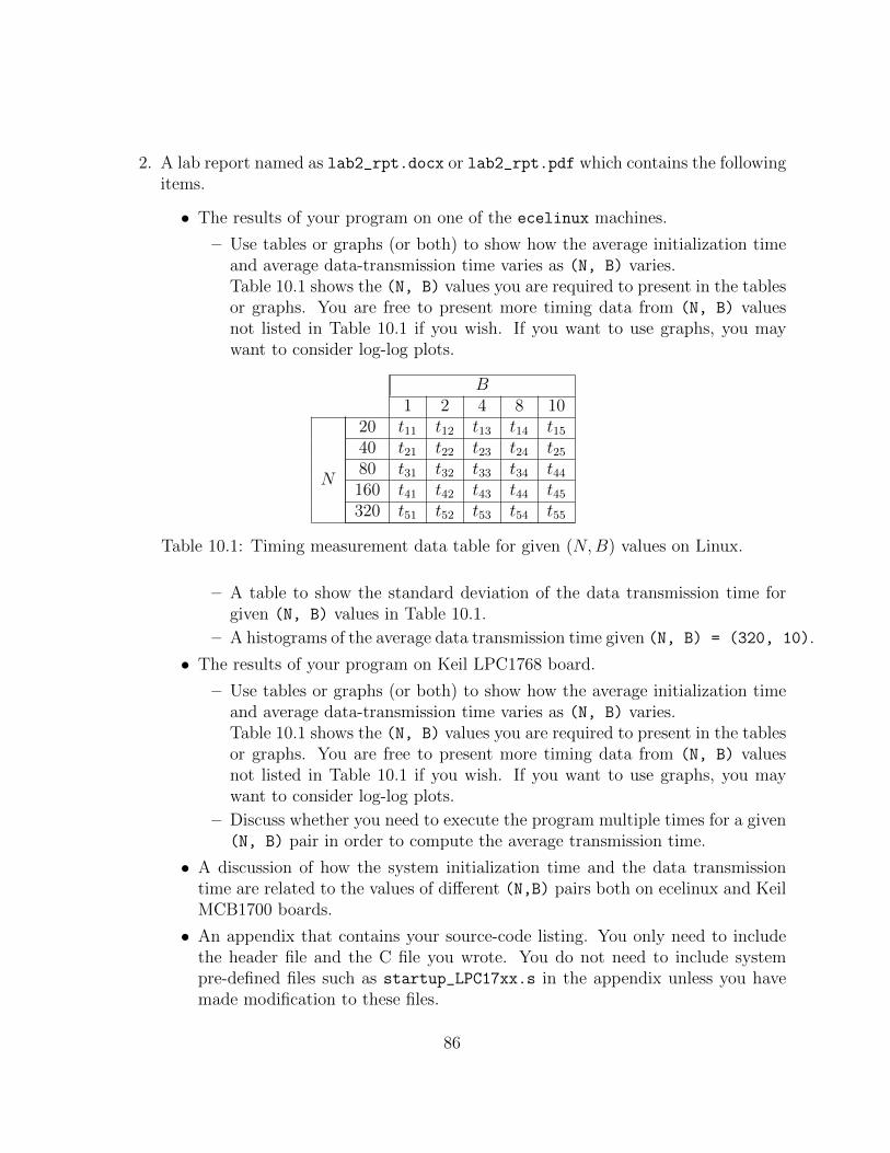
2. A lab report named as lab2_rpt.docx or lab2_rpt.pdf which contains the followingitems.
• The results of your program on one of the ecelinux machines.
– Use tables or graphs (or both) to show how the average initialization timeand average data-transmission time varies as (N, B) varies.Table 10.1 shows the (N, B) values you are required to present in the tablesor graphs. You are free to present more timing data from (N, B) valuesnot listed in Table 10.1 if you wish. If you want to use graphs, you maywant to consider log-log plots.
B1 2 4 8 10
N
20 t11 t12 t13 t14 t1540 t21 t22 t23 t24 t2580 t31 t32 t33 t34 t44160 t41 t42 t43 t44 t45320 t51 t52 t53 t54 t55
Table 10.1: Timing measurement data table for given (N,B) values on Linux.
– A table to show the standard deviation of the data transmission time forgiven (N, B) values in Table 10.1.
– A histograms of the average data transmission time given (N, B) = (320, 10).
• The results of your program on Keil LPC1768 board.
– Use tables or graphs (or both) to show how the average initialization timeand average data-transmission time varies as (N, B) varies.Table 10.1 shows the (N, B) values you are required to present in the tablesor graphs. You are free to present more timing data from (N, B) valuesnot listed in Table 10.1 if you wish. If you want to use graphs, you maywant to consider log-log plots.
– Discuss whether you need to execute the program multiple times for a given(N, B) pair in order to compute the average transmission time.
• A discussion of how the system initialization time and the data transmissiontime are related to the values of different (N,B) pairs both on ecelinux and KeilMCB1700 boards.
• An appendix that contains your source-code listing. You only need to includethe header file and the C file you wrote. You do not need to include systempre-defined files such as startup_LPC17xx.s in the appendix unless you havemade modification to these files.
86

10.8 Report Marking Rubric
The Rubric for marking the submitted source code and report is listed in Table 10.2.
Points Sub-Points Description
15 Source Code
3 The program can be built and run8 Correct implementation of the algorithm2 Suffcient system call error checking2 Appropriate code comments. Note too much, not
too less.
20 Report
8 Timing measurement results of ecelinux6 Timing measurement results of Keil MCB1700
boards6 A discussion of how the system initialization time
and the data transmission time are related to thevalues of different (N,B) pairs both on ecelinuxand Keil MCB1700 boards.
Table 10.2: Lab2 Marking Rubric
87

Chapter 11
Lab3: Thread Concurrency Control
11.1 Objective
This lab is to learn about, and gain practical experience in concurrency control for thepurpose of inter-thread communication by shared memory and compare its performancewith inter-process/task communication by message passing. In particular, you will use thePOSIX pthread library in a general Linux environment and RL-RTX on the Keil LPC1768board.
Sharing data among threads in a gerneal Linux environment is trivial because threadsshare the same memory [6]. For the Keil RL-RTX tasks, they share the same addressingspace, hence behave similar as threads.
The challenging part of sharing memory is to avoid race conditions. In a general Linuxenvironment, pthread semaphore and mutex library calls are to be used for thread mutualexclusion. In RL-RTX, semaphore and mutex management functions are to be used fortask communication mutual exclusion.
After this lab, students will have a good understanding of, and ability to program with
• the pthread pthread_create() and pthread_join() to create and join threads,
• the pthread sem_int(), sem_post() and sem_wait() library calls for inter-threadcommunication concurrency control in a general Linux environment, and
• the use of semaphore or mutex management APIs in RL-RTX for inter-task commu-nication concurrency control.
88

11.2 Starter files
• Your lab3 source code.
11.3 Pre-lab Preparation
1. Read Linux man page of semaphore overview.man 7 sem_overview
2. Read Sections 4.1, 4.4 and 4.5 about thread programming in [6].
3. Read supplementary materials regarding POSIX pthread in [5]
(http://www.cs.cf.ac.uk/Dave/C/node29.html#SECTION002940000000000000000).
4. Read the Keil µVision4 RL-ARM Real-time Library User’s Guide (a help file withinthe IDE). Under the RL-RTX section, the subsection Function Overview containsmore detailed description on semaphore management and mutex management rou-tines.
11.4 Lab3 Assignment
Solve the producer-consumer problem with a bounded buffer in a general Linux environ-ment and on the Keil LPC 1768 board. This is a classic multi-tasking problem in whichthere are one or more tasks that create data (these tasks are referred to as “producers”) andone or more tasks that use the data (these tasks are referred to as “consumers”). We willhave a system of P producers and C consumers . Three experimental cases then exist: sin-gle producer/single consumer; single producer/multi-consumer; multi-producer/single con-sumer.
The producer tasks will generate a fixed number, N, integers, one at a time. Since thereis more than one producer, and we do not want the producers to have to coordinate theiractions since that would require additional inter-thread/task communication, we will adoptthe following approach: each producer has an identity number, id, from 0 to P-1. Theproducer with identity number id will produce the integers i such that i%P == id. Forexample, if there are 7 producers, producer number 3 will produce the integers 3, 10, 17,. . . . Each time a new number is created, it is placed into a fixed-size buffer, size B integers,shared with the consumer tasks. When there are B integers in the buffer, producers stopproducing.
89

Each consumer is likewise given an integer identity, cid, from 0 to C-1. Each consumertask reads the integer out of the buffer, one at a time, and calculates the square root of theinteger. When the square root of the integer is itself an integer, the consumer prints outits identity, the original integer taken from the buffer, and the value of the square root onthe terminal screen (in Linux) or through UART (on Keil LPC1768 board). For example,if there are 6 consumers and consumer with cid = 3 read the value 16 from the buffer, itwill display 3 16 4.
Given that the buffer has a fixed size, B, and assuming that N > B, it is possible for theproducers to have produced enough integers that the buffer is filled before any consumerhas read any data. If this happens, the producer is blocked, and must wait till there is atleast one free spot in the buffer.
Similarly, it is possible for the consumers to read all of the data from the buffer, andyet more data is expected from the producers. In such a case, the consumer is blocked,and must wait for the producers to deposit one or more additional integers into the buffer.
Further, if any given producer or consumer is using the buffer, all other consumers andproducers must wait, pending that usage being finished. That is, all access to the bufferrepresents a critical section, and must be protected as such.
The program terminates when the consumers have read all N characters from the pro-ducers and finish displaying all square roots that are integers. Note that this is morecomplex than in the first lab, because you have multiple consumers that are reading fromthe buffer, and thus will need to determine whether or not some consumer has read thelast integer.
Question: Is there a similar problem for the producers to deal with, or is their situationsimpler?
Requirements
Let N be the number of integers the producers should produce and B be the buffer size.Your program will execute and then print out the time it takes to consume all N integerson the terminal/UART;
Let P be the number of producers and C be the number of consumers. For a set ofgiven <P,C,N,B> tuple values, run your application and measure the time it takes. Notefor a give value of <P,C,N,B>, you may need to run multiple times to compute the averageexecution time.
In a general Linux environment, compare the performance of multi-thread communica-tion by shared memory with multi-process communication by message queue.
90

1. Create a process with a fixed buffer size in which producers and consumers are threadswithin the process.
2. Extend Lab2 Linux implementation to multiple producers and multiple consumerscase and use message queue for inter-process communications. Note that you startyour program with one process which then forks multiple producer processes andmultiple consumer processes.
On the Keil LPC1768 board, compare the performance of multi-task communicationby shared memory with multi-task communication by mailbox.
1. Create producers and consumers tasks with a fixed buffer size in which the buffer isa shared global data structure among tasks.
2. Extend Lab2 LPC1768 implementation to multiple producers and multiple consumerscase and use mailbox for inter-task communications.
11.5 Deliverables
11.5.1 Pre-lab Deliverables
There is no pre-lab deliverable for this lab.
11.5.2 Post-lab Deliverables
Submit the following two items to the course book system before the deadline. Unless younotify the lab TAs and the lab instructor by email, we will mark the latest submissionwhen there are multiple submissions presented.
1. Entire lab3 µVision project folder and all source code for Linux platform.Zip the entire source code and name the .zip file lab3_src.zip.
2. A lab report named as lab3_rpt.docx or lab3_rpt.pdf. which contains the follow-ing items.
• Timing analysis for Linux environment
91

– Two tables that show the average timing measurement data for the (P,C,N,B)values shown in Table 11.1 for a general Linux environment. One table isfor the timing result by the approach of inter-thread communication withshared memory. Another table is for the timing result by the approach ofinter-process communication with message queue. Note that for each rowin the table, you need to run the program X (you decide the value of X)times and compute the average time.
P C N B Time1 1 100 42 1 100 43 1 100 41 2 100 41 3 100 41 1 100 82 1 100 83 1 100 81 2 100 81 3 100 81 1 398 82 1 398 83 1 398 81 2 398 81 3 398 8
Table 11.1: Timing measurement data table for given (P,C,N,B) values.
– Given (P,C,N,B) = (1, 3, 398, 8), run your program X times (you decidethe value of X) on Linux platform. Present the average timing measurementdata and its standard deviation.
– Compare the timing results of multi-thread with shared memory and multi-process with message queue. Discuss the advantages and disadvantages ofthese two approaches to solve the same problem.
• Timing analysis for Keil LPC1768 board
– Two tables that show the timing measurement data for for the (P,C,N,B)
values shown in Table 11.1. One table is for the timing result by the ap-proach of inter-task communication with shared memory. Another tableis for the timing result by the approach of inter-task communication withmessage queue. You only need to run your application once in order to fillthe tables.
92

– Given (P,C,N,B) = (1, 3, 398, 8), run your program X times (you decidethe value of X) on the Keil LPC1768 board. Compute the average timingmeasurement data and its standard deviation.
– Compare the timing results of multi-task with shared memory and multi-task with message queue. Discuss the advantages and disadvantages ofthese two approaches to solve the same problem.
• Add an appendix in the report which contains your source code of the producerand consumer well as any other routine that create these processes/tasks. Notethat you are required to comment the code appropriately so that any otherprogrammer can follow your algorithms and logic.
11.6 Report Marking Rubric
The Rubric for marking the submitted source code and report is listed in Table 11.2.
93

Points Sub-Points I Sub-Points II Description
20 Source Code
5 Code compilation15 Correct implementation of the algo-
rithm and execution gives the expectedresults
30 Report
15 Timing measurement results ofecelinux
6 Average timing measurement results3 Data transmission mean and
standard deviation results given(P,C,N,B) =(1,3,398,8).
6 Discussion of the advantages and dis-advantages of POSIX queue amonghprocesses and shared memory amongthread
15 Timing measurement results of KeilMCB1700 boards
6 Average timing measurement results3 Data transmission mean and
standard deviation results given(P,C,N,B) =(1,3,398,8).
6 Discussion of the advantages and disad-vantages of mailbox and shared mem-ory among tasks.
Table 11.2: Lab3 Marking Rubric
94

Chapter 12
Lab4: Porting POSIX MessageQueue to ARM RL-RTX
12.1 Objective
This lab is to learn about, and gain practical experience in POSIX message queue. Inparticular, you will create a set of POSIX compliant APIs to open a message queue, sendmessage, receive message and remove a message queue by modifying the RL-RTX libraryon Keil LPC1768 boards.
After this lab, students will have a good understanding of, and ability to, the following:
• Program message queue facility
• Add POSIX compliant APIs to RTX-RL library
12.2 Pre-lab Preparation
1. Read the man page (section 7) of mq_overview
(http://linux.die.net/man/7/mq_overview)
2. Study the rt_Mailbox.c in RL-RTX source.
95

12.3 Lab4 Assignment
POSIX message queues provide a familiar interface for many realtime/embedded program-mers. They are similar to the mailboxes found in RTX-RL library.
POSIX messages queues implement a store-and-forward design in which the sender neednot block and may have many outstanding messages queued. POSIX message queues existindependently of the processes that use them. You would likely use message queues in adesign where a number of named queues will be operated on by a variety of processes overtime.
The APIs you are required to implement are as follows
mqd_t mq_open(const char *name, int oflag);
mqd_t mq_unlink(const char *name);
mqd_t mq_send(mqd_t mqdes, const char *msg_ptr,
size_t msg_len, unsigned msg_prio);
mqd_t mq_receive(mqd_t mqdes, char *msg_ptr,
size_t msg_len, unsigned *msg_prio);
Requirements
1. Implement the four POSIX message queue APIs listed above (refer the man page ofthese APIs on linux for detailed descriptions).
2. Write a set of test tasks to show that
• a queue can be opened;
• a queue can be removed;
• tasks can send and receive different sizes of messages;
• tasks can send and receive messages of the same priority;
• tasks can send and receive messages of different priorities;
• mq_send() and mq_receive() can be blocking or non-blocking calls dependingon the setting of oflag in mq_open().
96

P C N B Time1 1 100 162 1 100 163 1 100 161 2 100 161 3 100 161 1 100 322 1 100 323 1 100 321 2 100 321 3 100 321 1 398 322 1 398 323 1 398 321 2 398 321 3 398 32
Table 12.1: Timing measurement data table for given (P,C,N,B) values.
3. Modify your lab2 Linux multi-process message queue code to use POSIX queue andexecute it on the Keil board after you integrate your POSIX queue APIs into KeilRL-RTX.
4. Write a system manual about
• the design and implementation of your POSIX message queue APIs and testingtasks, including, but not limited to, data structure and algorithms to managequeues and testing plans. The system manual will be evaluated based on howwell it describes your design and testing plans.
• Timing Analysis results of running your modified Linux lab2 on Keil LPC1768using the POSIX message queue APIs.
– Two tables that show the timing measurement data for for the (P,C,N,B)
values shown in table 12.1. One table is for the timing result by the approachof inter-task communication with shared memory. Another table is for thetiming result by the approach of inter-task communication with messagequeue. You only need to run your application once in order to fill thetables.
– Given (P,C,N,B) = (1, 3, 398, 32), run your program X times (you decidethe value of X) on the Keil LPC1768 board. Compute the average timing
97

measurement data and its standard deviation.
– Under the condition that 0 < P + C < 5, analyzing your experiment data,discuss what is the optimal number of producer tasks and consumer tasksgiven (N,B) = (398, 32). It would be good if you can explain the reasonwhy the optimal (P,C) value you find performs the best.
– Compare the timing results of using the POSIX queue on Keil with the tim-ing results of your lab2 Keil producer-consumer using mailbox. Discuss theadvantages and disadvantages of these two approaches and cost differencesto solve the same problem.
Demonstration
This lab requires a demo of your system to a lab TA. Demo reservation will be done throughcourse book system. Each demo is 20-30 minutes. Both group members are required toattend the demo. You will get 0 mark on this lab if you miss the demo without 48 hournotice.
12.4 Lab Deliverables
12.4.1 Pre-Lab Deliverables
There is no pre-lab deliverable for this lab
12.4.2 Post-Lab Deliverables
Submit a .zip file with name lab4.zip that contains the following two items to the coursebook system before the deadline. Unless you notify the lab TAs and the lab instructor byemail, we will mark the latest submission when there are multiple submissions presented.
• Entire lab4 µVision project folder
• A system manual
98

Appendix A
Forms
Lab administration related forms are given in this appendix.
99

ECE254/MTE241 Request to Leave a Project Group Form
Name:Quest ID:Student ID:Lab Assignment IDGroup ID:Name of Other Group Members:
Provide the reason for leaving the project group here:
Signature Date
100

Bibliography
[1] MCB1700 User’s Guide. http://www.keil.com/support/man/docs/mcb1700. 14
[2] MDK Primer. http://www.keil.com/support/man/docs/gsac. 54, 55, 56
[3] Realview compilation tools version 4.0: Compiler reference guide, 2007-2010. 61
[4] LPC17xx User Manual, Rev2.0, 2010. 13, 16, 17, 20, 34, 51, 57
[5] AD Marshall. Programming in c unix system calls and subroutines using c. Availableon-line at http://www.cs.cf.ac.uk/Dave/C/CE.html, 1999. 89
[6] M. Mitchell, J. Oldham, and A. Samuel. Advanced linux programming. Availableon-line at http://advancedlinuxprogramming.com, 2001. 82, 88, 89
[7] W. Stallings. Operating systems: internals and design principles. Prentice Hall, seventhedition, 2011. xi, 83, 84
[8] J. Yiu. The Definitive Guide to the ARM Cortex-M3. Newnes, 2009. xi, 16, 18, 22, 23,54, 60
101