ECE 477 Design Review Team 5 Spring 2009
47
ECE 477 Design Review ECE 477 Design Review Team 5 Team 5 Spring 2009 Spring 2009
-
Upload
clayton-bryan -
Category
Documents
-
view
26 -
download
0
description
ECE 477 Design Review Team 5 Spring 2009. Project Overview. Inertial based character recognition device Battery powered pen Wall/battery powered base station Wireless communication betwixt pen and base. L. Project-Specific Success Criteria. - PowerPoint PPT Presentation
Transcript of ECE 477 Design Review Team 5 Spring 2009

ECE 477 Design Review ECE 477 Design Review Team 5 Team 5 Spring 2009 Spring 2009

Project OverviewProject Overview
• Inertial based character recognition deviceInertial based character recognition device• Battery powered penBattery powered pen• Wall/battery powered base stationWall/battery powered base station• Wireless communication betwixt pen and baseWireless communication betwixt pen and base
L

Project-Specific Success CriteriaProject-Specific Success Criteria
• An ability to initiate the drawing of a character.An ability to initiate the drawing of a character.• An ability to match and display characters on An ability to match and display characters on
an LCD screen.an LCD screen.• An ability to monitor battery life and display An ability to monitor battery life and display
status.status.• An ability to interpret data from accelerometers An ability to interpret data from accelerometers
as characters.as characters.• An ability to transmit data wirelessly to a base An ability to transmit data wirelessly to a base
device.device.

Block DiagramBlock Diagram
~3ADXL330(Accelerometer)
PIC18F2320(Microcontroller)
MRF24J40MA(Transceiver)
LTC4150(Fuel Gauge)
7
dsPIC33FJ128GP204(Microcontroller)
MRF24J40MA(Transceiver)
7
HD44780U(LCD)
10
LTC4150(Fuel Gauge)
LTC4054-4.2(Battery Charger)
Pen Base Station

Overall Design ConstraintsOverall Design Constraints
• PenPen– PCB small enough to fit on a penPCB small enough to fit on a pen– Low enough power consumption to run off batteriesLow enough power consumption to run off batteries– Proper peripherals to interface with wireless transceiver Proper peripherals to interface with wireless transceiver
(SPI in master mode) and accelerometers (3 ATD channels)(SPI in master mode) and accelerometers (3 ATD channels)• Base Station Base Station
– Proper peripherals to interface with wireless transceiver Proper peripherals to interface with wireless transceiver (SPI in master mode)(SPI in master mode)
– Enough I/O pins to interface with LCD DisplayEnough I/O pins to interface with LCD Display– Large FLASH memoryLarge FLASH memory

Component Selection ADXL330Component Selection ADXL330
• ‘‘Usable’ packageUsable’ package– LFCSPLFCSP
• Analog signalAnalog signal• 1.8-3.6V1.8-3.6V• 3-Axis3-Axis• 4×4×1.45mm 4×4×1.45mm • Alternative: ADXL 213Alternative: ADXL 213

Component Selection MRF24J40MAComponent Selection MRF24J40MA
• Integration with Integration with microcontrollersmicrocontrollers
• Usable packageUsable package– Surface MountSurface Mount
• All inclusiveAll inclusive• 2.4-3.6V2.4-3.6V• 17.8 mm x 27.9 mm17.8 mm x 27.9 mm• Alternative: Meshnetics Alternative: Meshnetics
MNZB-24-A2 using MNZB-24-A2 using ATmega 1281v MCUATmega 1281v MCU

Component Selection PIC18LF2320Component Selection PIC18LF2320
• 1-SPI; 3-ATD; 1-SPI; 3-ATD; • Software stack for Software stack for
MiWi protocolMiWi protocol• 3.3KB PMemory 3.3KB PMemory
(8192B)(8192B)• 200B Ram (512B)200B Ram (512B)
• 2-5.5V2-5.5V• 0.3 in x 1.4 in0.3 in x 1.4 in• Internal OscillatorInternal Oscillator• Well supportedWell supported

Component Selection dsPIC33FJ128Gp204Component Selection dsPIC33FJ128Gp204
• 1 SPI1 SPI• Software stack for MiWi Software stack for MiWi
protocolprotocol• 3-3.6V3-3.6V• 6 x 6 x 0.9 mm6 x 6 x 0.9 mm• 128KB program memory128KB program memory• Well supportedWell supported• Alternative: Alternative:
dsPIC33FJ64GP306dsPIC33FJ64GP306• 64 GPIO pins64 GPIO pins• 64kB PMemory64kB PMemory

Power Consumption & Battery LifePower Consumption & Battery Life• Pen Pen
– Two Duracell Rechargeable NiMH AA batteries in Two Duracell Rechargeable NiMH AA batteries in seriesseries
– 1800 mAh1800 mAh– 5.5 hours estimated battery life5.5 hours estimated battery life
Component Description
Part #. Current Consumption(mA)
Operating Voltage(V)
Transceiver MRF24J40MA
23 (Tx Mode) 2.4 – 3.6
Microcontroller PIC18LF2320
300 2 – 5.5
Accelerometer ADXL330 0.18 1.8-3.6
Total 323.18

Power Consumption & Battery LifePower Consumption & Battery Life• Base StationBase Station
– Ultralife Li-Ion Rechargeable battery Ultralife Li-Ion Rechargeable battery – 1800 mAh1800 mAh– 8 hours of battery life8 hours of battery life
Component Descriptions
Part #. Current Consumption(mA)
Operating Voltage(V)
Transceiver MRF24J40MA
19 (Rx mode) 2.4 – 3.6
Microcontroller dsPIC33FJ128GP204
200 3 – 3.6
LCD Display LCD16x4BL 4 5
Total 223

Packaging DesignPackaging Design

Pen Power ManagementPen Power Management
Fuel Gauge
Battery Headers 3.3V Boost

Pen Power ManagementPen Power Management
3V (2AA)
3.3V
Possibly remove?

Pen Power ManagementPen Power Management
3V (2AA)

Pen PIC/PeripheralsPen PIC/Peripherals
AccelerometerMicrocontroller
Transmitter
Transmitter Header
ICD2 HeaderAxes Signals
Pen Tip

AccelerometerAccelerometer

MicrocontrollerMicrocontroller
1) VDD2) PGM3) PGC4) PGD5) Reset6) Ground

TransceiverTransceiver

Base Station PowerBase Station Power
4V DC LDO
Fuel Gauge
Battery Charger
3.3V Buck
5V Boost
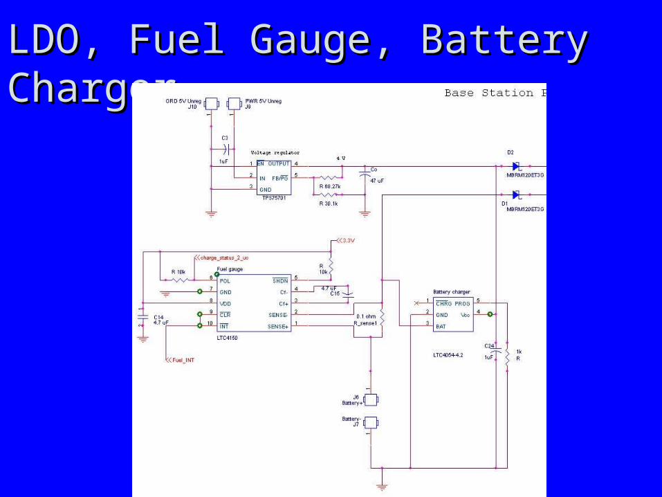
LDO, Fuel Gauge, Battery ChargerLDO, Fuel Gauge, Battery Charger

5V Boost and 3.3 V Buck5V Boost and 3.3 V Buck

Base Station PIC/PeripheralsBase Station PIC/PeripheralsPIC
LCD Header
Transceiver
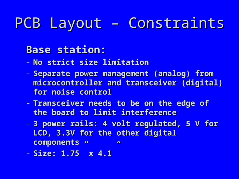
PCB Layout – ConstraintsPCB Layout – Constraints
Base station:Base station:- No strict size limitationNo strict size limitation- Separate power management (analog) from Separate power management (analog) from
microcontroller and transceiver (digital) for noise microcontroller and transceiver (digital) for noise controlcontrol
- Transceiver needs to be on the edge of the board Transceiver needs to be on the edge of the board to limit interferenceto limit interference
- 3 power rails: 4 volt regulated, 5 V for LCD, 3.3V 3 power rails: 4 volt regulated, 5 V for LCD, 3.3V for the other digital componentsfor the other digital components
- Size: 1.75” x 4.1”Size: 1.75” x 4.1”

PCB Layout – Base stationPCB Layout – Base station

PCB Layout – Base station (T)PCB Layout – Base station (T)

PCB Layout – Base station (B)PCB Layout – Base station (B)

PCB Layout – Base stationPCB Layout – Base station(ground)(ground)

PCB Layout – Base stationPCB Layout – Base station(4 V)(4 V)

PCB Layout – Base stationPCB Layout – Base station(5 V)(5 V)

PCB Layout – Base stationPCB Layout – Base station(3.3 V)(3.3 V)
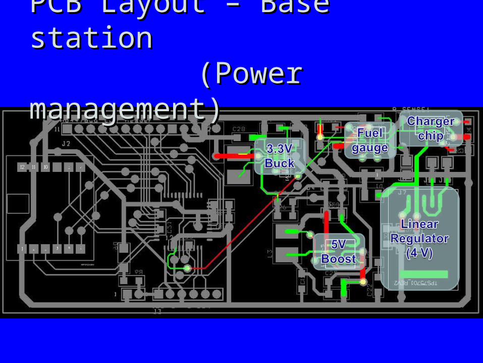
PCB Layout – Base stationPCB Layout – Base station (Power management) (Power management)

PCB Layout – Base stationPCB Layout – Base station(dsPIC33)(dsPIC33)

PCB Layout – Base stationPCB Layout – Base station (Transceiver) (Transceiver)

PCB Layout – ConstraintsPCB Layout – Constraints
Portable device (pen):Portable device (pen):- Tight size constraintsTight size constraints- Keep analog traces from accelerometers as short Keep analog traces from accelerometers as short
as possible; accelerometers close to the tip of the as possible; accelerometers close to the tip of the penpen
- Transceiver needs to be on the edge of the board Transceiver needs to be on the edge of the board to limit interference (preferably on top)to limit interference (preferably on top)
- Size: 1.3” x 4.2”Size: 1.3” x 4.2”

PCB Layout – Portable device PCB Layout – Portable device
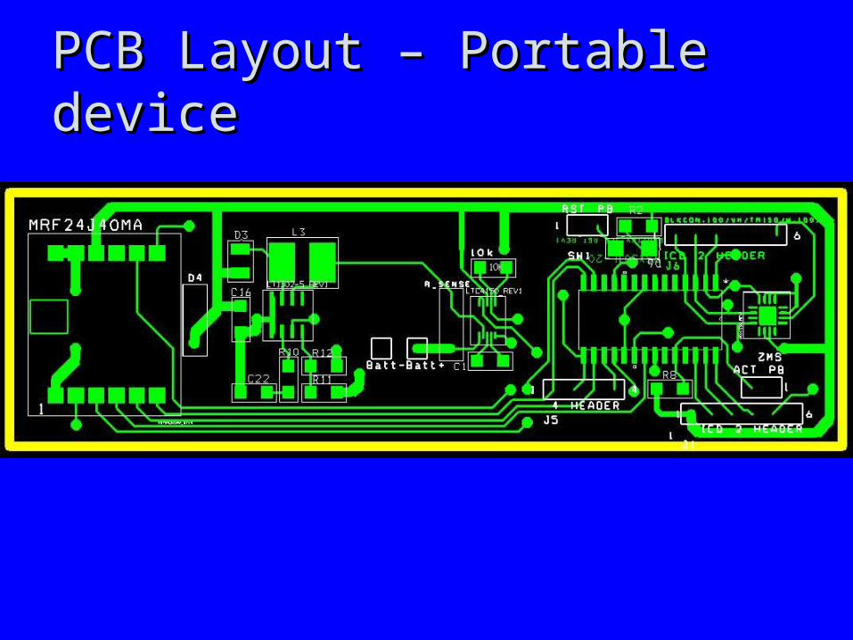
PCB Layout – Portable device PCB Layout – Portable device

PCB Layout – Portable device PCB Layout – Portable device

PCB– Portable device (ground)PCB– Portable device (ground)

PCB– Portable device (3.3 V)PCB– Portable device (3.3 V)

PCB– Portable device PCB– Portable device (Accelerometers) (Accelerometers)

PCB– Portable device (PIC18)PCB– Portable device (PIC18)
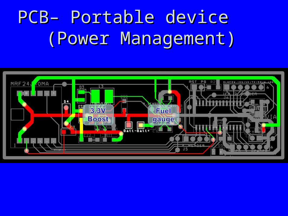
PCB– Portable device PCB– Portable device (Power Management)(Power Management)

PCB– Portable device PCB– Portable device (Transceiver)(Transceiver)

Software Design/Development StatusSoftware Design/Development Status
Pen
Base Station

Project Completion TimelineProject Completion Timeline

Questions / DiscussionQuestions / Discussion