ECE 448 Lecture 6
87
George Mason University Finite State Machines State Diagrams, State Tables, Algorithmic State Machine (ASM) Charts, and VHDL Code ECE 448 Lecture 6
-
Upload
gannon-hebert -
Category
Documents
-
view
41 -
download
1
description
ECE 448 Lecture 6. Finite State Machines State Diagrams, State Tables, Algorithmic State Machine (ASM) Charts, and VHDL Code. Required reading. P. Chu, FPGA Prototyping by VHDL Examples Chapter 5, FSM. Recommended reading. - PowerPoint PPT Presentation
Transcript of ECE 448 Lecture 6

George Mason University
Finite State Machines
State Diagrams,State Tables,
Algorithmic State Machine (ASM) Charts, and VHDL Code
ECE 448Lecture 6

2
Required reading
• P. Chu, FPGA Prototyping by VHDL Examples
Chapter 5, FSM

3
Recommended reading
• S. Brown and Z. Vranesic, Fundamentals of Digital Logic with VHDL Design
Chapter 8, Synchronous Sequential Circuits
Sections 8.1-8.5
Section 8.10, Algorithmic State Machine (ASM)
Charts

4
Datapath
vs.
Controller
5
Structure of a Typical Digital System
Datapath(Execution
Unit)
Controller(Control
Unit)
Data Inputs
Data Outputs
Control & Status Inputs
Control & Status Outputs
Control Signals
StatusSignals

6
Datapath (Execution Unit)
• Manipulates and processes data• Performs arithmetic and logic operations,
shifting/rotating, and other data-processing tasks
• Is composed of registers, multiplexers, adders, decoders, comparators, ALUs, gates, etc.
• Provides all necessary resources and interconnects among them to perform specified task
• Interprets control signals from the Controller and generates status signals for the Controller

7
Controller (Control Unit)
• Controls data movement in the Datapath by switching multiplexers and enabling or disabling resources
Example: enable signals for registersExample: select signals for muxes
• Provides signals to activate various processing tasks in the Datapath
• Determines the sequence of operations performed by the Datapath
• Follows Some ‘Program’ or Schedule
8
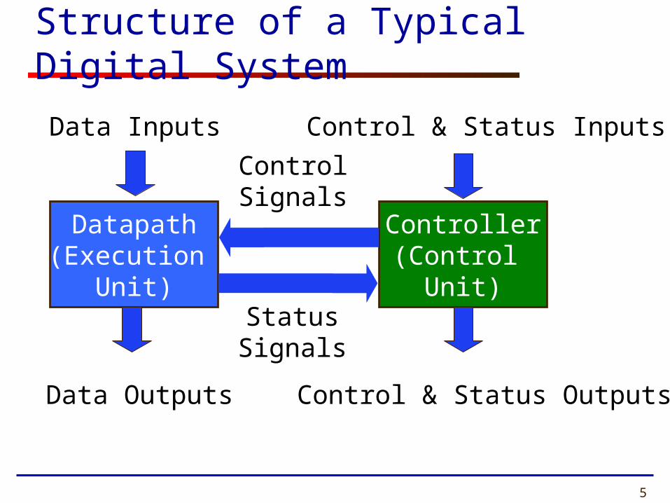
Programmable vs. Non-Programmable Controller
• Controller can be programmable or non-programmable• Programmable
• Has a program counter which points to next instruction• Instructions are held in a RAM or ROM• Microprocessor is an example of programmable
controller• Non-Programmable
• Once designed, implements the same functionality• Another term is a “hardwired state machine,” or
“hardwired FSM,” or “hardwired instructions”• In this course we will be focusing on non-
programmable controllers.
9
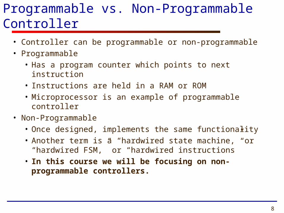
Finite State Machines
• Controllers can be described as Finite State Machines (FSMs)
• Finite State Machines can be represented using• State Diagrams and State Tables - suitable
for simple controllers with a relatively few inputs and outputs
• Algorithmic State Machine (ASM) Charts - suitable for complex controllers with a large number of inputs and outputs
• All of these descriptions can be easily translated to the corresponding synthesizable VHDL code

10
Hardware Design with RTL VHDL
Pseudocode
Datapath Controller
Block
diagram
Block
diagram
State diagram
or ASM chart
VHDL code VHDL code VHDL code
Interface

Steps of the Design Process1. Text description2. Interface3. Pseudocode4. Block diagram of the Datapath5. Interface divided into Datapath and Controller 6. State diagram or ASM chart of the Controller
7. RTL VHDL code of the Datapath, Controller, and Top-Level Unit
8. Testbench for the Datapath, Controller, and Top-Level Unit
9. Functional simulation and debugging10. Synthesis and post-synthesis simulation11. Implementation and timing simulation12. Experimental testing using FPGA board
11

1. Text description2. Interface3. Pseudocode4. Block diagram of the Datapath5. Interface divided into Datapath and Controller6. State diagram or ASM chart of the Controller
7. RTL VHDL code of the Datapath, Controller, and Top-level Unit
8. Testbench for the Datapath, Controller, and Top-Level Unit
9. Functional simulation and debugging10. Synthesis and post-synthesis simulation11. Implementation and timing simulation12. Experimental testing using FPGA board
Steps of the Design ProcessIntroduced in Class Today
12

13
Finite State Machines
Refresher

14
Finite State Machines (FSMs)• An FSM is used to model a system that transits
among a finite number of internal states. The transitions depend on the current state and external input.
• The main application of an FSM is to act as the controller of a medium to large digital system
• Design of FSMs involves
• Defining states
• Defining next state and output functions
• Optimization / minimization
• Manual optimization/minimization is practical for small FSMs only

15
Moore FSM
• Output is a Function of the Present State Only
Present Stateregister
Next Statefunction
Outputfunction
Inputs
Present StateNext State
Outputs
clockreset

16
Mealy FSM• Output is a Function of the Present State and the
Inputs
Next Statefunction
Outputfunction
Inputs
Present StateNext State
Outputs
Present Stateregister
clockreset

17
State Diagrams

18
Moore Machine
state 1 /output 1
state 2 /output 2
transitioncondition 1
transitioncondition 2

19
Mealy Machine
state 1 state 2
transition condition 1 /output 1
transition condition 2 /output 2

20
Moore FSM - Example 1
• Moore FSM that Recognizes Sequence “10”
S0 / 0 S1 / 0 S2 / 1
00
0
1
11
reset
Meaning of states:
S0: No elements of the sequenceobserved
S1: “1”observed
S2: “10”observed

21
Mealy FSM - Example 1
• Mealy FSM that Recognizes Sequence “10”
S0 S1
0 / 0 1 / 0 1 / 0
0 / 1reset
Meaning of states:
S0: No elements of the sequenceobserved
S1: “1”observed
22
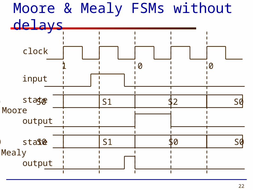
Moore & Mealy FSMs without delays
clock
input
Moore
Mealy
0 1 0 0 0
S0 S0 S1 S2 S0 S0
S0 S0 S1 S0 S0 S0
state
output
state
output

23
Moore & Mealy FSMs with delays
clock
input
Moore
Mealy
0 1 0 0 0
S0 S0 S1 S2 S0 S0
S0 S0 S1 S0 S0 S0
state
output
state
output

24
Moore vs. Mealy FSM (1)
• Moore and Mealy FSMs Can Be Functionally Equivalent• Equivalent Mealy FSM can be derived from
Moore FSM and vice versa
• Mealy FSM Has Richer Description and Usually Requires Smaller Number of States• Smaller circuit area

25
Moore vs. Mealy FSM (2)
• Mealy FSM Computes Outputs as soon as Inputs Change• Mealy FSM responds one clock cycle sooner
than equivalent Moore FSM
• Moore FSM Has No Combinational Path Between Inputs and Outputs• Moore FSM is less likely to affect the critical
path of the entire circuit

26
Moore vs. Mealy FSM (3)
• Types of control signal• Edge sensitive
• E.g., enable signal of a counter• Both can be used but Mealy is faster
• Level sensitive• E.g., write enable signal of SRAM• Moore is preferred

27
Which Way to Go?
Safer.Less likely to affect
the critical path.
Mealy FSM Moore FSM
Lower Area
Responds one clockcycle earlier
Fewer states

Problem 1
Assuming state diagram given on the next slide, supplement timing waveforms given in the answer sheet
with the correct values of signals State and c, in the interval from 0 to 575 ns.

Z
Reset
X
Y
0-/1
1-/0
-1/0
-0/1
-0/1
-1/0

Clk
a
b
State
c
Reset
0 ns 100 ns 200 ns 300 ns 400 ns 500 ns

31
Finite State Machines
in VHDL

32
FSMs in VHDL
• Finite State Machines Can Be Easily Described With Processes
• Synthesis Tools Understand FSM Description if Certain Rules Are Followed• State transitions should be described in a
process sensitive to clock and asynchronous reset signals only
• Output function described using rules for combinational logic, i.e. as concurrent statements or a process with all inputs in the sensitivity list
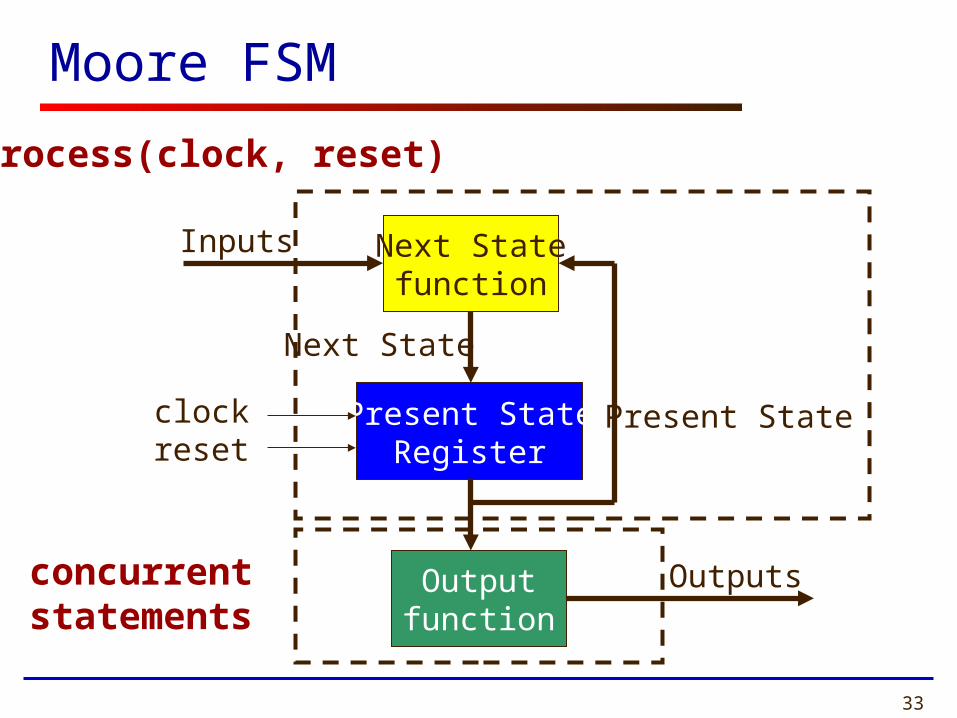
33
Moore FSM
Present StateRegister
Next Statefunction
Outputfunction
Inputs
Present State
Next State
Outputs
clockreset
process(clock, reset)
concurrent statements

34
Mealy FSM
Next Statefunction
Outputfunction
Inputs
Present StateNext State
Outputs
Present StateRegister
clockreset
process(clock, reset)
concurrent statements

35
Moore FSM - Example 1
• Moore FSM that Recognizes Sequence “10”
S0 / 0 S1 / 0 S2 / 1
00
0
1
11
reset

36
Moore FSM in VHDL (1)
TYPE state IS (S0, S1, S2);SIGNAL Moore_state: state;
U_Moore: PROCESS (clock, reset)BEGIN
IF(reset = ‘1’) THENMoore_state <= S0;
ELSIF rising_edge(clock) THENCASE Moore_state IS
WHEN S0 => IF input = ‘1’ THEN
Moore_state <= S1; ELSE Moore_state <= S0; END IF;

37
Moore FSM in VHDL (2)
WHEN S1 => IF input = ‘0’ THEN
Moore_state <= S2; ELSE Moore_state <= S1; END IF;
WHEN S2 => IF input = ‘0’ THEN
Moore_state <= S0; ELSE
Moore_state <= S1; END IF;
END CASE;END IF;
END PROCESS;
Output <= ‘1’ WHEN Moore_state = S2 ELSE ‘0’;

38
Mealy FSM - Example 1
• Mealy FSM that Recognizes Sequence “10”
S0 S1
0 / 0 1 / 0 1 / 0
0 / 1reset
39
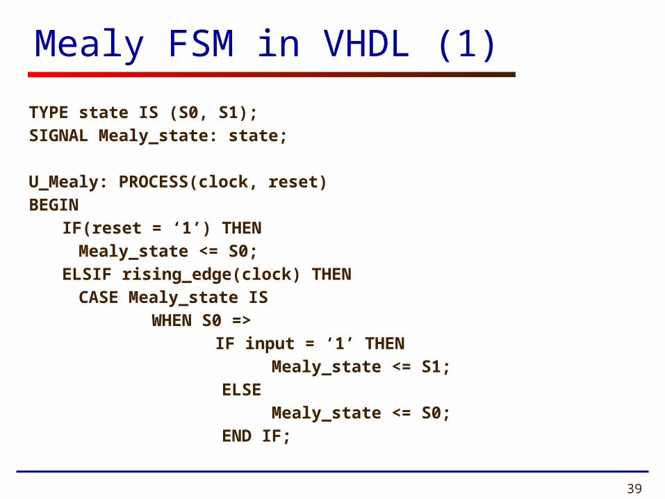
Mealy FSM in VHDL (1)
TYPE state IS (S0, S1);SIGNAL Mealy_state: state;
U_Mealy: PROCESS(clock, reset)BEGIN
IF(reset = ‘1’) THENMealy_state <= S0;
ELSIF rising_edge(clock) THENCASE Mealy_state IS
WHEN S0 => IF input = ‘1’ THEN
Mealy_state <= S1; ELSE Mealy_state <= S0; END IF;

40
Mealy FSM in VHDL (2)
WHEN S1 => IF input = ‘0’ THEN
Mealy_state <= S0; ELSE Mealy_state <= S1; END IF;
END CASE;END IF;
END PROCESS;
Output <= ‘1’ WHEN (Mealy_state = S1 AND input = ‘0’) ELSE ‘0’;

41
Algorithmic State Machine (ASM)
Charts

42
Algorithmic State Machine
Algorithmic State Machine –
representation of a Finite State Machine
suitable for FSMs with a larger number of inputs and outputs compared to FSMs expressed using state diagrams and state tables.

43
Elements used in ASM charts (1)
Output signalsor actions
(Moore type)
State name
Condition expression
0 (False) 1 (True)
Conditional outputs or actions (Mealy type)
(a) State box (b) Decision box
(c) Conditional output box
44
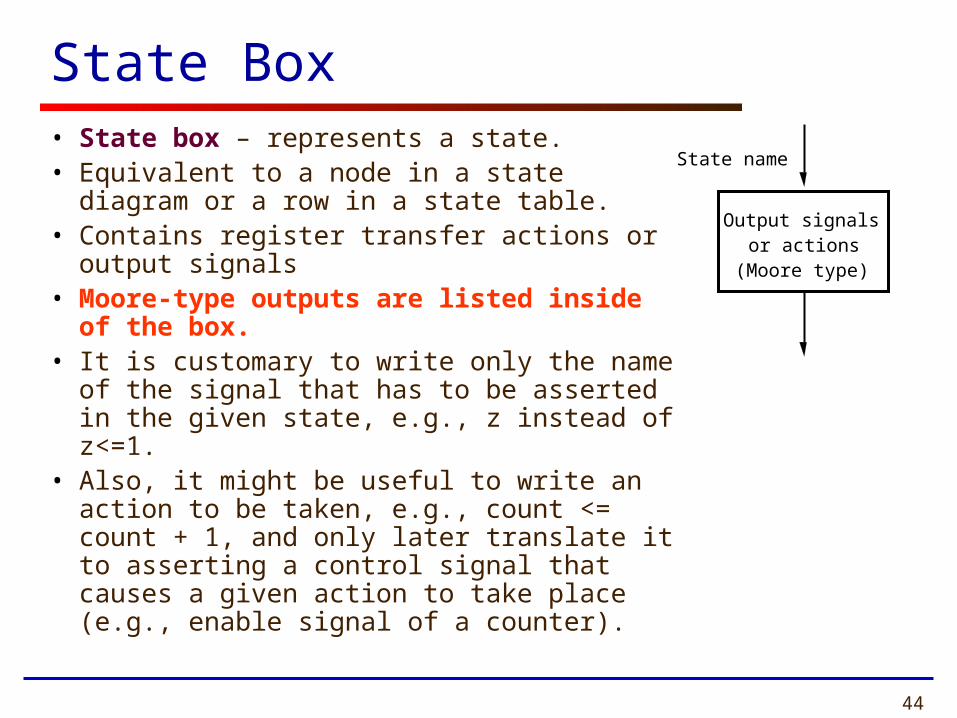
State Box• State box – represents a state.• Equivalent to a node in a state diagram or a
row in a state table.• Contains register transfer actions or output
signals• Moore-type outputs are listed inside of
the box. • It is customary to write only the name of the
signal that has to be asserted in the given state, e.g., z instead of z<=1.
• Also, it might be useful to write an action to be taken, e.g., count <= count + 1, and only later translate it to asserting a control signal that causes a given action to take place (e.g., enable signal of a counter).
Output signalsor actions
(Moore type)
State name

45
Decision Box
• Decision box – indicates that a given condition is to be tested and the exit path is to be chosen accordingly.
The condition expression may include one or more inputs to the FSM.
Condition expression
0 (False) 1 (True)

46
Conditional Output Box
• Conditional output box
• Denotes output signals that are of the Mealy type.
• The condition that determines whether such outputs are generated is specified in the decision box.
Conditional outputs or actions (Mealy type)

47
ASMs representing simple FSMs
• Algorithmic state machines can model both Mealy and Moore Finite State Machines
• They can also model machines that are of the mixed type

48
Generalized FSM
Based on RTL Hardware Design by P. Chu

49
Moore FSM – Example 2: State diagram
C z 1 =
Reset
B z 0 = A z 0 = w 0 =
w 1 =
w 1 =
w 0 =
w 0 = w 1 =
50
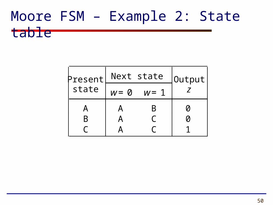
Present Next state Outputstate w = 0 w = 1 z
A A B 0 B A C 0 C A C 1
Moore FSM – Example 2: State table

51
w
w
w 0 1
0
1
0
1
A
B
C
z
Reset
w
w
w 0 1
0
1
0
1
A
B
C
z
Reset
ASM Chart for Moore FSM – Example 2

52
USE ieee.std_logic_1164.all ;
ENTITY simple ISPORT ( Clock : IN STD_LOGIC ;
Reset : IN STD_LOGIC ; w : IN STD_LOGIC ;
z : OUT STD_LOGIC ) ;END simple ;
ARCHITECTURE Behavior OF simple ISTYPE State_type IS (A, B, C) ;SIGNAL y : State_type ;
BEGINPROCESS ( Reset, Clock )BEGIN
IF Reset = '1' THENy <= A ;
ELSIF rising_edge(Clock) THEN
Example 2: VHDL code (1)

53
CASE y ISWHEN A =>
IF w = '1' THEN y <= B ;
ELSE y <= A ;
END IF ;WHEN B =>
IF w = '1' THENy <= C ;
ELSEy <= A ;
END IF ;WHEN C =>
IF w = '1' THENy <= C ;
ELSEy <= A ;
END IF ;END CASE ;
Example 2: VHDL code (2)

54
Example 2: VHDL code (3)
END IF ;
END PROCESS ;
z <= '1' WHEN y = C ELSE '0' ;
END Behavior ;
55
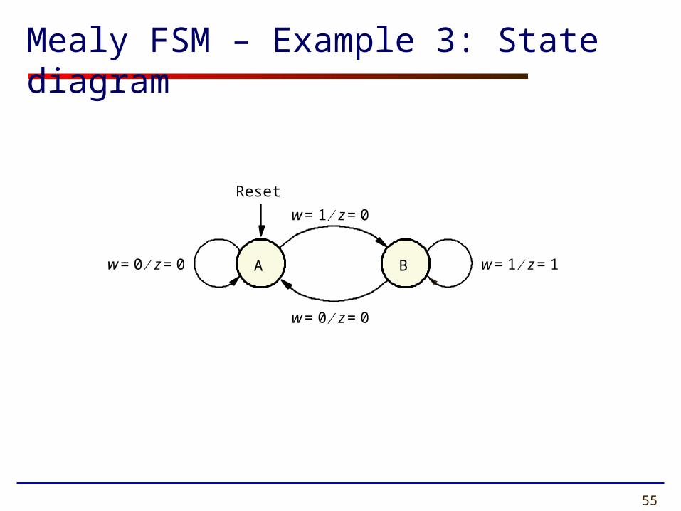
A
w 0 = z 0 =
w 1 = z 1 = B w 0 = z 0 =
Reset
w 1 = z 0 =
Mealy FSM – Example 3: State diagram

56
ASM Chart for Mealy FSM – Example 3
w
w 0 1
0
1
A
B
Reset
z

57
LIBRARY ieee ;USE ieee.std_logic_1164.all ;
ENTITY Mealy ISPORT ( Clock : IN STD_LOGIC ;
Reset : IN STD_LOGIC ; w : IN STD_LOGIC ;
z : OUT STD_LOGIC ) ;END Mealy ;
ARCHITECTURE Behavior OF Mealy ISTYPE State_type IS (A, B) ;SIGNAL y : State_type ;
BEGINPROCESS ( Reset, Clock )BEGIN
IF Reset = '1' THENy <= A ;
ELSIF rising_edge(Clock) THEN
Example 3: VHDL code (1)

58
Example 3: VHDL code (2)
CASE y IS WHEN A => IF w = '1' THEN
y <= B ;ELSE
y <= A ;END IF ;
WHEN B =>IF w = '1' THEN
y <= B ;ELSE
y <= A ; END IF ;END CASE ;

59
Example 3: VHDL code (3)
END IF ;
END PROCESS ;
z <= '1' WHEN (y = B) AND (w=’1') ELSE '0' ;
END Behavior ;

60
Control Unit Example: Arbiter (1)
Arbiter
reset
r1
r2
r3
g1
g2
g3
clock

61
Idle
000
1--
Reset
gnt1 g 1 1 =
-1-
gnt2 g 2 1 =
--1
gnt3 g 3 1 =
0-- 1--
01- -0-
001 --0
Control Unit Example: Arbiter (2)
62
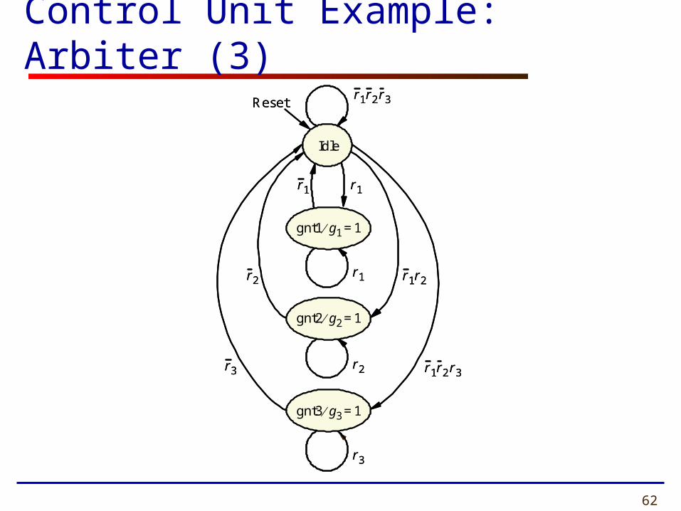
Control Unit Example: Arbiter (3)
r 1 r 2
r 1 r 2 r 3
Idle
Reset
gnt1 g 1 1 =
gnt2 g 2 1 =
gnt3 g 3 1 =
r 1 r 1
r 1
r 2
r 3
r 2
r 3
r 1 r 2 r 3
r 1 r 2
r 1 r 2 r 3
Idle
Reset
gnt1 g 1 1 =
gnt2 g 2 1 =
gnt3 g 3 1 =
r 1 r 1
r 1
r 2
r 3
r 2
r 3
r 1 r 2 r 3

63
ASM Chart for Control Unit - Example 4
r 1
r 3 0 1
1
Idle
Reset
r 2
r 1
r 3
r 2
gnt1
gnt2
gnt3
1
1
1
0
0
0
g 1
g 2
g 3
0
0
1
r 1
r 3 0 1
1
Idle
Reset
r 2
r 1
r 3
r 2
gnt1
gnt2
gnt3
1
1
1
0
0
0
g 1
g 2
g 3
0
0
1

64
Example 4: VHDL code (1)
LIBRARY ieee;
USE ieee.std_logic_1164.all;
ENTITY arbiter IS
PORT ( Clock, Reset : IN STD_LOGIC ;
r : IN STD_LOGIC_VECTOR(1 TO 3) ;
g : OUT STD_LOGIC_VECTOR(1 TO 3) ) ;
END arbiter ;
ARCHITECTURE Behavior OF arbiter IS
TYPE State_type IS (Idle, gnt1, gnt2, gnt3) ;
SIGNAL y : State_type ;

65
Example 4: VHDL code (2)BEGIN
PROCESS ( Reset, Clock )
BEGIN
IF Reset = '1' THEN y <= Idle ;
ELSIF rising_edge(Clock) THEN
CASE y IS
WHEN Idle =>
IF r(1) = '1' THEN y <= gnt1 ;
ELSIF r(2) = '1' THEN y <= gnt2 ;
ELSIF r(3) = '1' THEN y <= gnt3 ;
ELSE y <= Idle ;
END IF ;
WHEN gnt1 =>
IF r(1) = '1' THEN y <= gnt1 ;
ELSE y <= Idle ;
END IF ;
WHEN gnt2 =>
IF r(2) = '1' THEN y <= gnt2 ;
ELSE y <= Idle ;
END IF ;
66
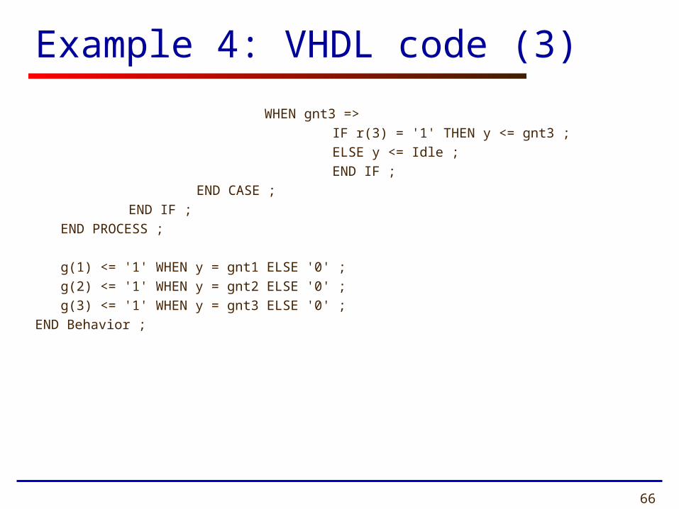
Example 4: VHDL code (3)
WHEN gnt3 =>
IF r(3) = '1' THEN y <= gnt3 ;
ELSE y <= Idle ;
END IF ;
END CASE ;
END IF ;
END PROCESS ;
g(1) <= '1' WHEN y = gnt1 ELSE '0' ;
g(2) <= '1' WHEN y = gnt2 ELSE '0' ;
g(3) <= '1' WHEN y = gnt3 ELSE '0' ;
END Behavior ;

Problem 2
Assuming ASM chart given on the next slide, supplement timing waveforms given in the answer
sheet with the correct values of signals State, g1, g2, g3, in the interval from 0 to 575 ns.

68
ASM Chart
r 1
r 3 0 1
1
Idle
Reset
r 2
r 1
r 3
r 2
gnt1
gnt2
gnt3
1
1
1
0
0
0
g 1
g 2
g 3
0
0
1
r 1
r 3 0 1
1
Idle
Reset
r 2
r 1
r 3
r 2
gnt1
gnt2
gnt3
1
1
1
0
0
0
g 1
g 2
g 3
0
0
1

Clk
r1
r2
State
Reset
r3
g1
g2
g3
0 ns 100 ns 200 ns 300 ns 400 ns 500 ns

70
ASM Summary by Prof. Chu
• ASM (algorithmic state machine) chart – Flowchart-like diagram – Provides the same info as a state diagram– More descriptive, better for complex description– ASM block
• One state box• One or more optional decision boxes:
with T (1) or F (0) exit path• One or more conditional output boxes:
for Mealy output

71

72
ASM Chart Rules
Based on RTL Hardware Design by P. Chu
• Difference between a regular flowchart and an ASM chart:– Transition governed by clock – Transition occurs between ASM blocks
• Basic rules:– For a given input combination, there is one
unique exit path from the current ASM block– Any closed loop in an ASM chart must
include a state box

73
Incorrect ASM Charts
Based on RTL Hardware Design by P. Chu

74
Generalized FSM
Based on RTL Hardware Design by P. Chu

75
Alternative Coding Styles
by Dr. Chu
(to be used with caution)
76
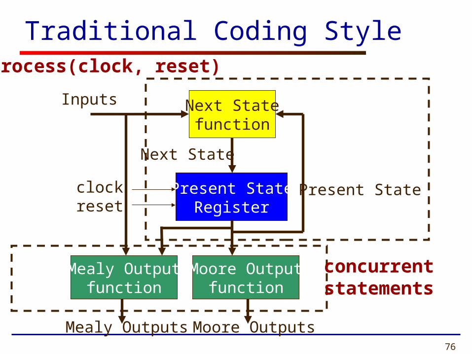
Traditional Coding Style
Present StateRegister
Next Statefunction
Moore Outputfunction
Inputs
Present State
Next State
clockreset
process(clock, reset)
concurrent statements
Mealy Outputfunction
Mealy Outputs Moore Outputs

77
Alternative Coding Style 1
Present StateRegister
Next Statefunction
Moore Outputfunction
Inputs
Present State
Next State
clockreset
Process(Present State, Inputs)
Mealy Outputfunction
Mealy Outputs Moore Outputs
Process(clock, reset)
Process(Present State)Process(Present State, Inputs)
RTL Hardware Design by P. Chu
Chapter 10 78
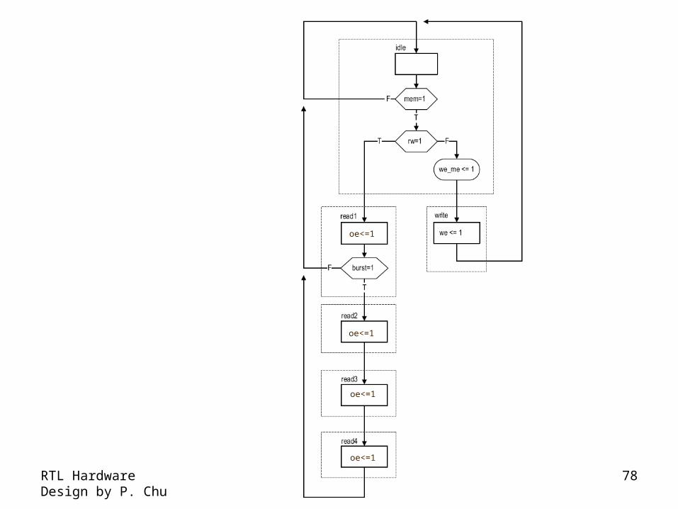
oe<=1
oe<=1
oe<=1
oe<=1

79
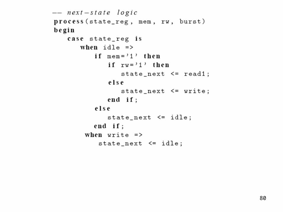
80
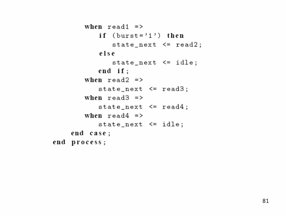
81

82

83
84
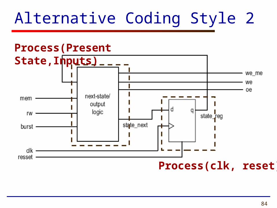
Alternative Coding Style 2
Process(clk, reset)
Process(Present State,Inputs)

85

86

87