ECE 445 –Optical Fiber Communications Lecture 01 ... · ECE 455 1 ECE 445 –Optical Fiber...
31
ECE 455 1 ECE 445 – Optical Fiber Communications Lecture 01 - Introduction • ECE 445 • Lecture 01 • Fall Semester 2016 Stavros Iezekiel Department of Electrical and Computer Engineering University of Cyprus [email protected]
Transcript of ECE 445 –Optical Fiber Communications Lecture 01 ... · ECE 455 1 ECE 445 –Optical Fiber...
ECE 455 1
ECE 445 – Optical Fiber Communications
Lecture 01 - Introduction
• ECE 445
• Lecture 01
• Fall Semester 2016
Stavros IezekielDepartment of Electrical and
Computer Engineering
University of Cyprus

ECE 455 2
ECE 455
Why is this course useful to you?
ECE 455 3
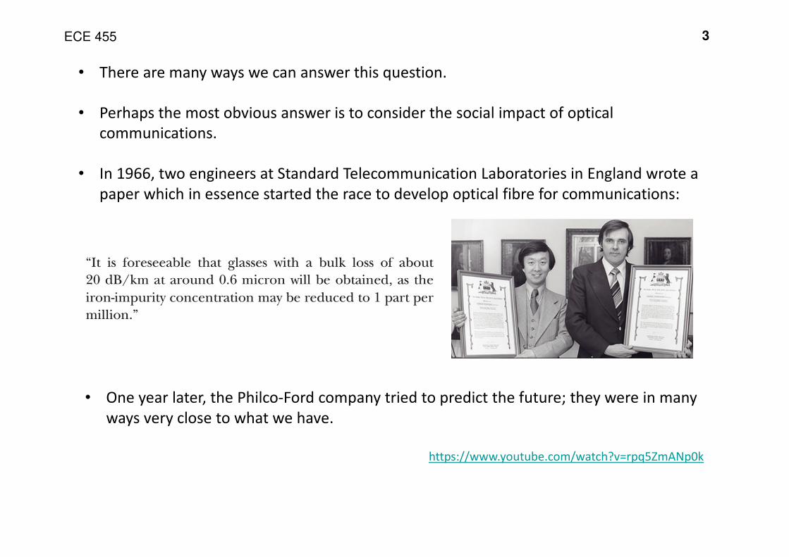
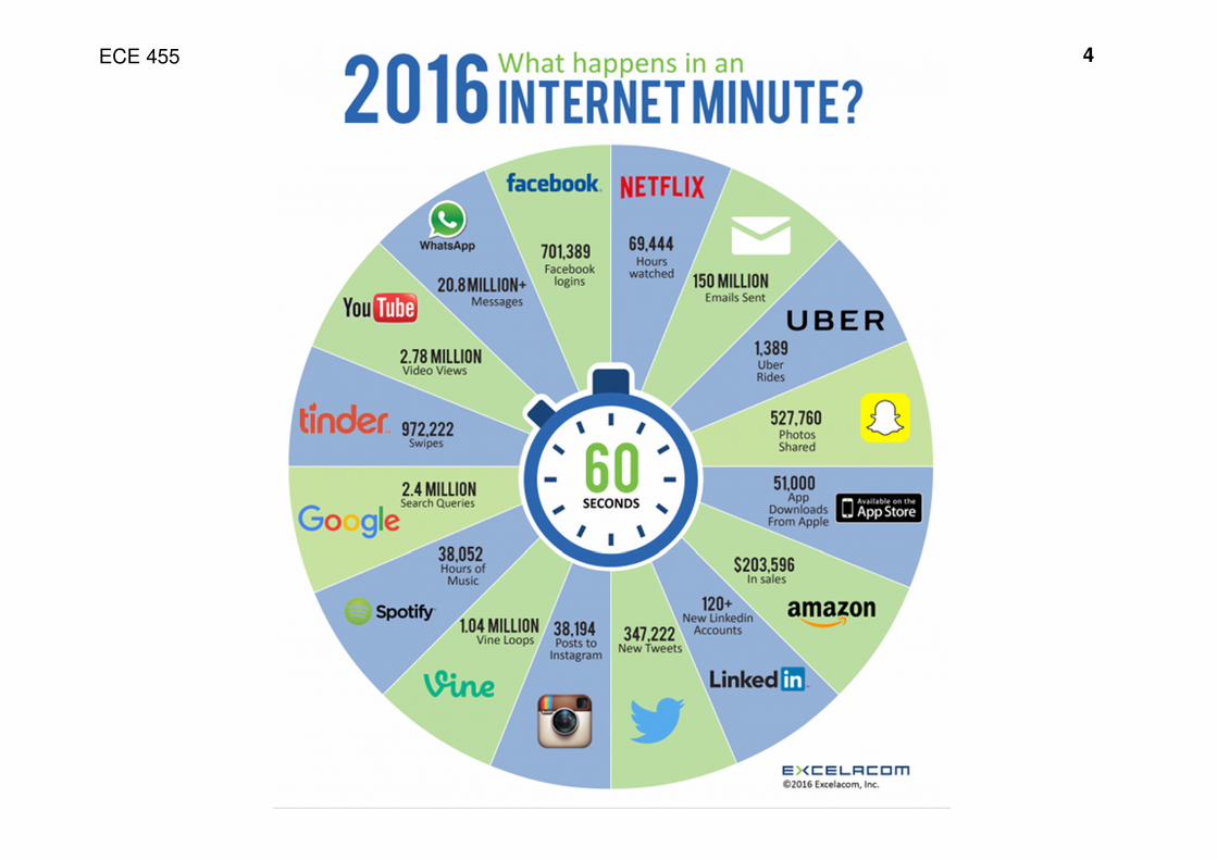
• There are many ways we can answer this question.
• Perhaps the most obvious answer is to consider the social impact of optical
communications.
• In 1966, two engineers at Standard Telecommunication Laboratories in England wrote a
paper which in essence started the race to develop optical fibre for communications:
• One year later, the Philco-Ford company tried to predict the future; they were in many
ways very close to what we have.
https://www.youtube.com/watch?v=rpq5ZmANp0k
ECE 455 4
ECE 455 5
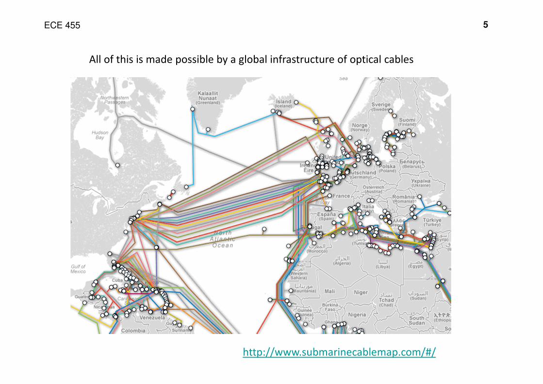
All of this is made possible by a global infrastructure of optical cables
http://www.submarinecablemap.com/#/
ECE 455 6
The aim of this course is to study optical fibre technology and its application to optical
communication links and systems
The basic questions we will seek to answer in the first few lectures include:
1. What are the advantages of using photonics for communications?
2. What is optical fibre?
3. What is an optical communications link? (Basic architecture)
4. How does light propagate in an optical fibre?
ECE 455
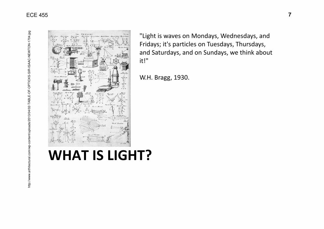
WHAT IS LIGHT?
7
htt
p:/
/ww
w.a
rthitectu
ral.com
/wp-c
onte
nt/
uplo
ads/2
013/0
4/0
2-T
AB
LE
-OF
-OP
TIC
KS
-SIR
-IS
AA
C-N
EW
TO
N-1
704.jpg
"Light is waves on Mondays, Wednesdays, and
Fridays; it's particles on Tuesdays, Thursdays,
and Saturdays, and on Sundays, we think about
it!"
W.H. Bragg, 1930.
ECE 455 8
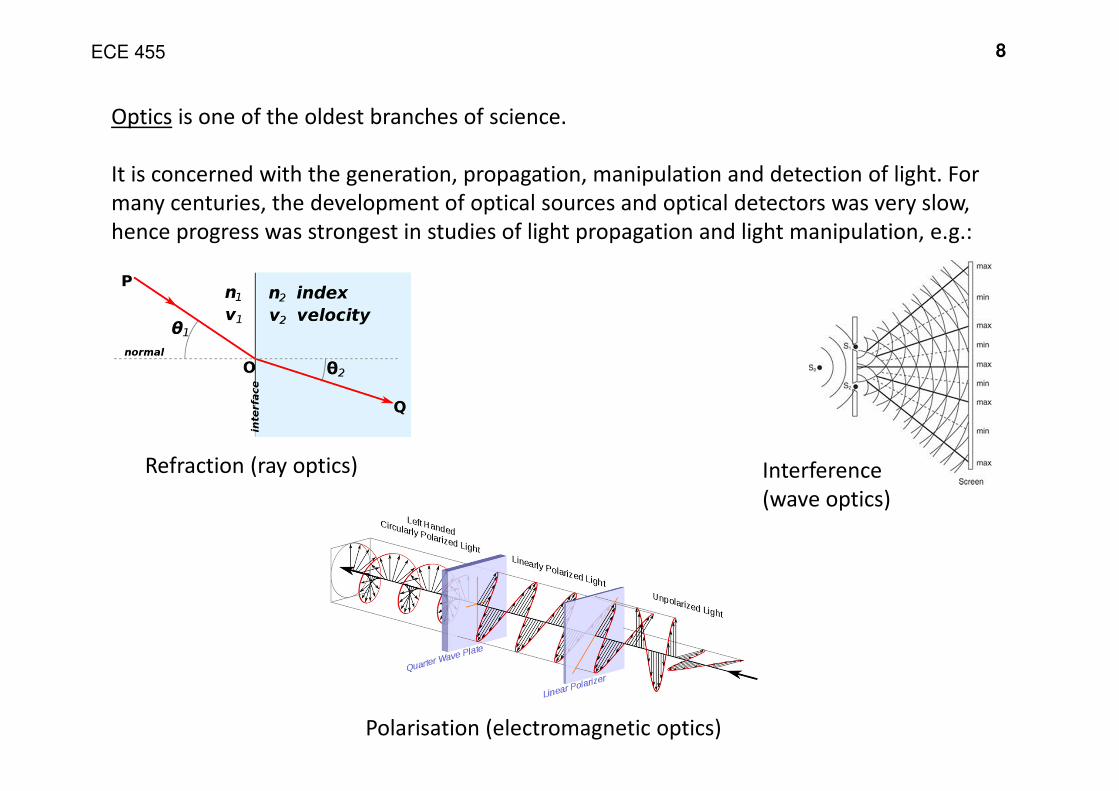
Optics is one of the oldest branches of science.
It is concerned with the generation, propagation, manipulation and detection of light. For
many centuries, the development of optical sources and optical detectors was very slow,
hence progress was strongest in studies of light propagation and light manipulation, e.g.:
Refraction (ray optics) Interference
(wave optics)
Polarisation (electromagnetic optics)
ECE 455 9
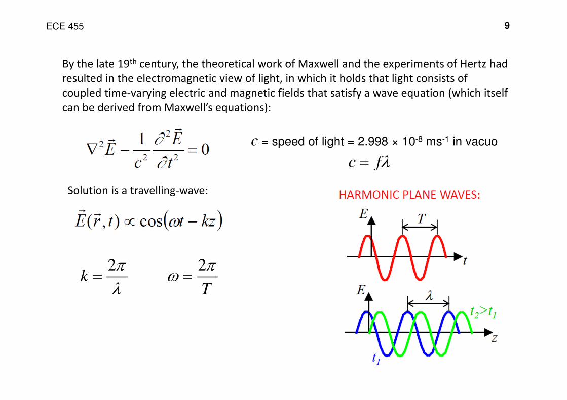
By the late 19th century, the theoretical work of Maxwell and the experiments of Hertz had
resulted in the electromagnetic view of light, in which it holds that light consists of
coupled time-varying electric and magnetic fields that satisfy a wave equation (which itself
can be derived from Maxwell’s equations):
c = speed of light = 2.998 × 10⁻⁸ ms-1 in vacuo
Solution is a travelling-wave:
λfc =
λ
π2=k
T
πω
2=
ECE 455 10
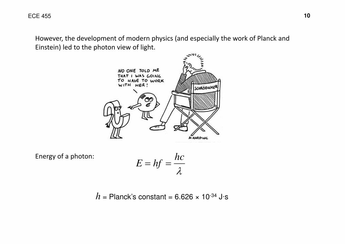
However, the development of modern physics (and especially the work of Planck and
Einstein) led to the photon view of light.
Energy of a photon:
λ
hchfE ==
h = Planck’s constant = 6.626 × 10⁻³⁴ J·s
ECE 455 11
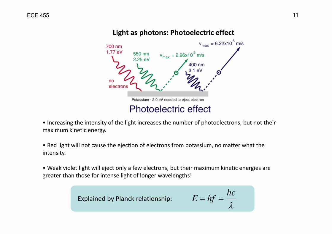
Light as photons: Photoelectric effect
• Increasing the intensity of the light increases the number of photoelectrons, but not their
maximum kinetic energy.
• Red light will not cause the ejection of electrons from potassium, no matter what the
intensity.
• Weak violet light will eject only a few electrons, but their maximum kinetic energies are
greater than those for intense light of longer wavelengths!
Explained by Planck relationship:λ
hchfE ==
ECE 455 12
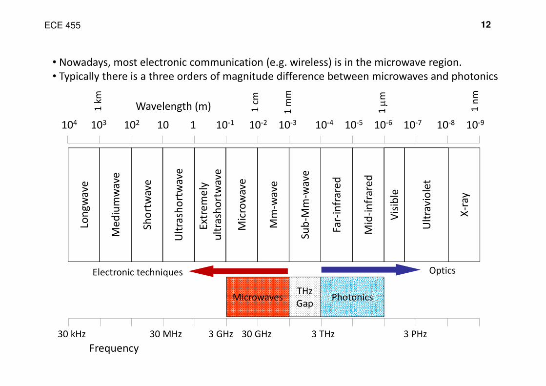
104 103 102 10 1 10-1 10-2 10-3 10-4 10-5 10-6 10-7 10-8 10-9
1 k
mWavelength (m) 1
mm
1 µ
m
1 n
m
1 c
m
Frequency
3 THz30 MHz 3 PHz30 GHz30 kHz 3 GHz
Lon
gw
ave
Me
diu
mw
ave
Sh
ort
wa
ve
Ult
rash
ort
wa
ve
Ext
rem
ely
ult
rash
ort
wa
ve
Mic
row
ave
Mm
-wa
ve
Su
b-M
m-w
ave
Far-
infr
are
d
Mid
-in
fra
red
X-r
ay
Vis
ible
Ult
rav
iole
t
Electronic techniques Optics
THz
GapMicrowaves Photonics
• Nowadays, most electronic communication (e.g. wireless) is in the microwave region.
• Typically there is a three orders of magnitude difference between microwaves and photonics
ECE 455
OPTICAL COMMUNICATIONS
13
ECE 455 14
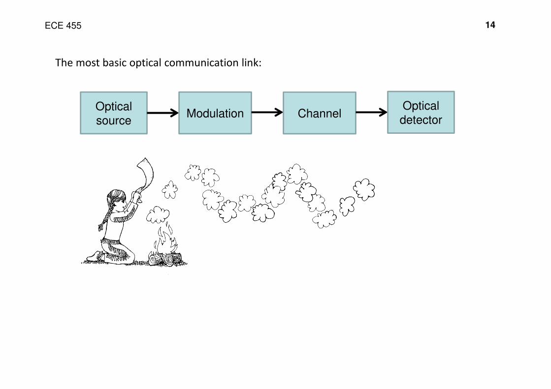
The most basic optical communication link:
Optical
sourceModulation Channel
Optical
detector
ECE 455 15
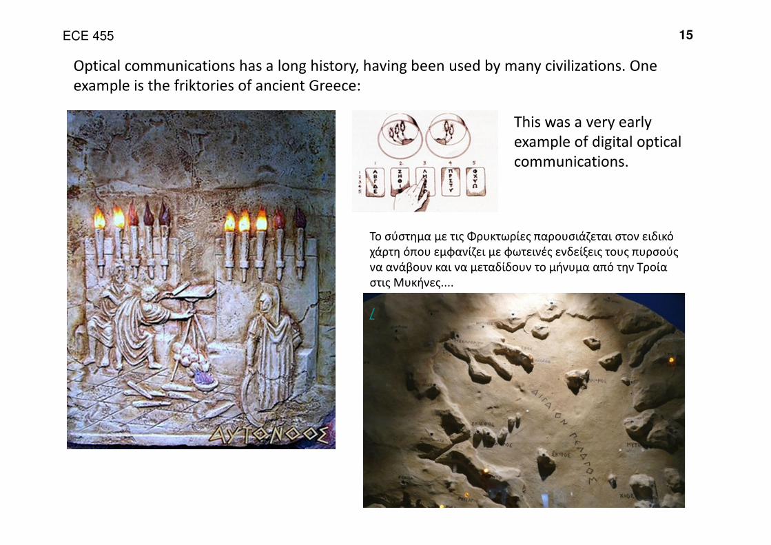
Optical communications has a long history, having been used by many civilizations. One
example is the friktories of ancient Greece:
This was a very early
example of digital optical
communications.
Το σύστημα με τις Φρυκτωρίες παρουσιάζεται στον ειδικό
χάρτη όπου εμφανίζει με φωτεινές ενδείξεις τους πυρσούς
να ανάβουν και να μεταδίδουν το μήνυμα από την Τροία
στις Μυκήνες....
/
ECE 455 16
htt
p://w
ww
.ec-lyon.f
r/to
urism
e/C
happe/
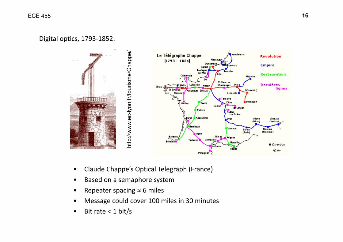
• Claude Chappe’s Optical Telegraph (France)
• Based on a semaphore system
• Repeater spacing ≈ 6 miles
• Message could cover 100 miles in 30 minutes
• Bit rate < 1 bit/s
Digital optics, 1793-1852:
ECE 455 17
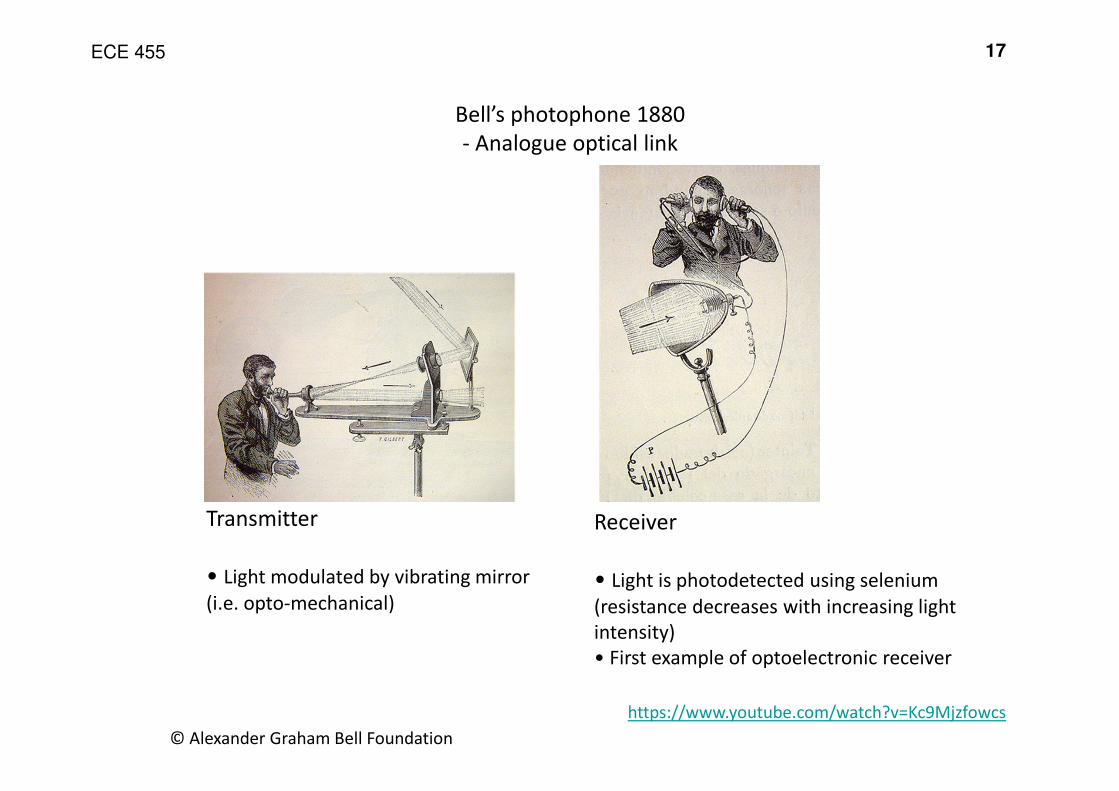
© Alexander Graham Bell Foundation
Transmitter
• Light modulated by vibrating mirror
(i.e. opto-mechanical)
Bell’s photophone 1880
- Analogue optical link
Receiver
• Light is photodetected using selenium
(resistance decreases with increasing light
intensity)
• First example of optoelectronic receiver
https://www.youtube.com/watch?v=Kc9Mjzfowcs
ECE 455 18
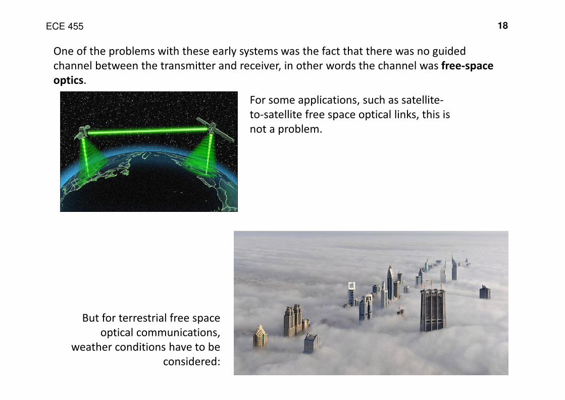
For some applications, such as satellite-
to-satellite free space optical links, this is
not a problem.
But for terrestrial free space
optical communications,
weather conditions have to be
considered:
One of the problems with these early systems was the fact that there was no guided
channel between the transmitter and receiver, in other words the channel was free-space
optics.
ECE 455 19
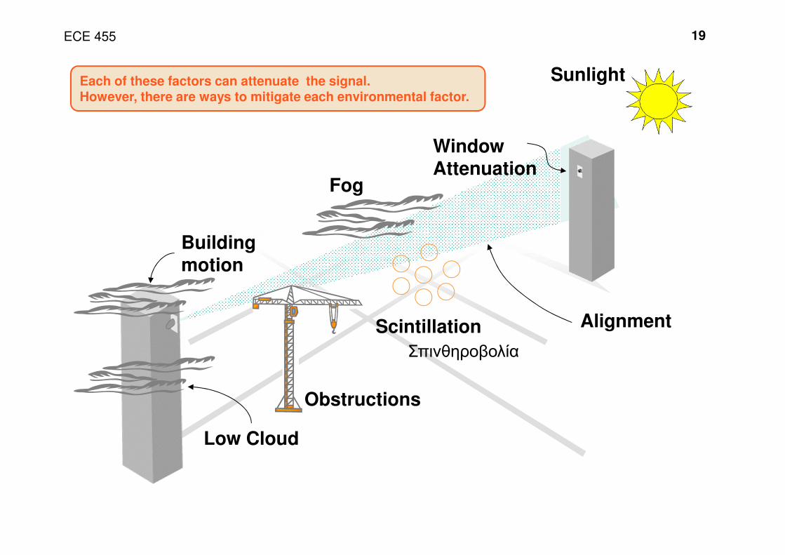
Sunlight
Building motion
Alignment
WindowAttenuation
Fog
Each of these factors can attenuate the signal. However, there are ways to mitigate each environmental factor.
Scintillation
Obstructions
Low Cloud
Σπινθηροβολία
ECE 455 20
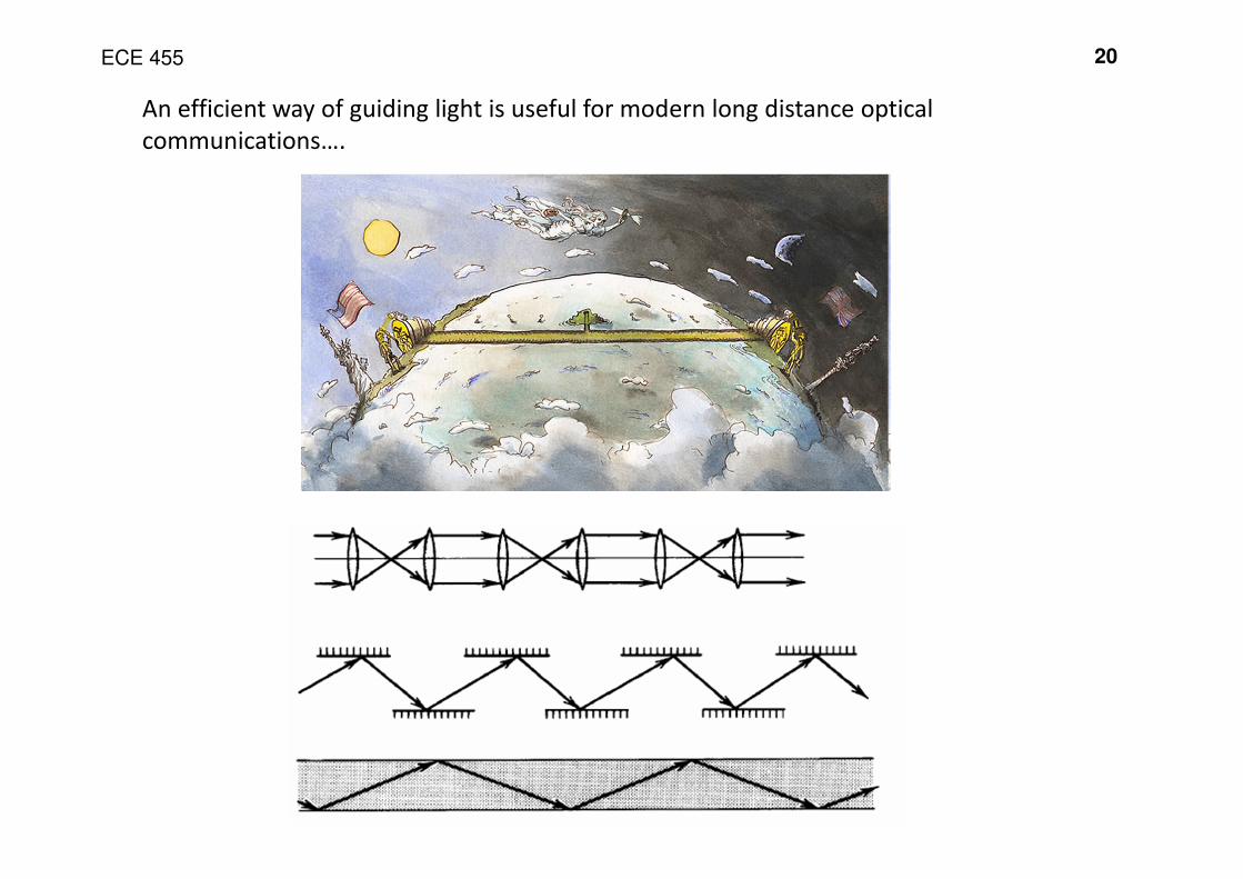
An efficient way of guiding light is useful for modern long distance optical
communications….
ECE 455 21
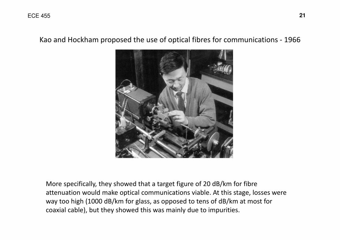
Kao and Hockham proposed the use of optical fibres for communications - 1966
More specifically, they showed that a target figure of 20 dB/km for fibre
attenuation would make optical communications viable. At this stage, losses were
way too high (1000 dB/km for glass, as opposed to tens of dB/km at most for
coaxial cable), but they showed this was mainly due to impurities.
ECE 455 22
107
106
105
104
103
102
10
1
0.1
3000 BC 1000 AD 1900 1966 1979 1983
Optical
Loss
(dB/km)
Egyptian
Venetian
Optical glass
Optical fibre
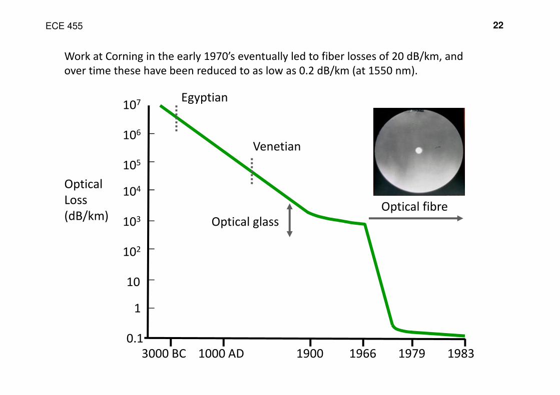
Work at Corning in the early 1970’s eventually led to fiber losses of 20 dB/km, and
over time these have been reduced to as low as 0.2 dB/km (at 1550 nm).
ECE 455 23
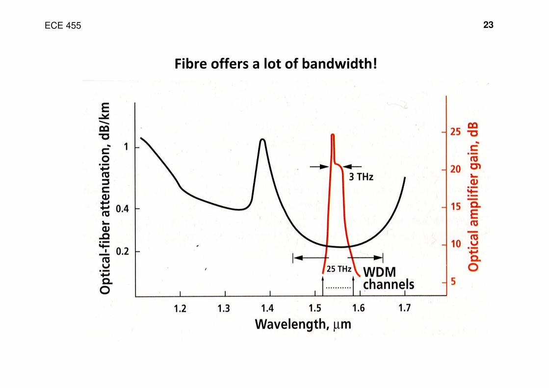
Fibre offers a lot of bandwidth!
ECE 455 24
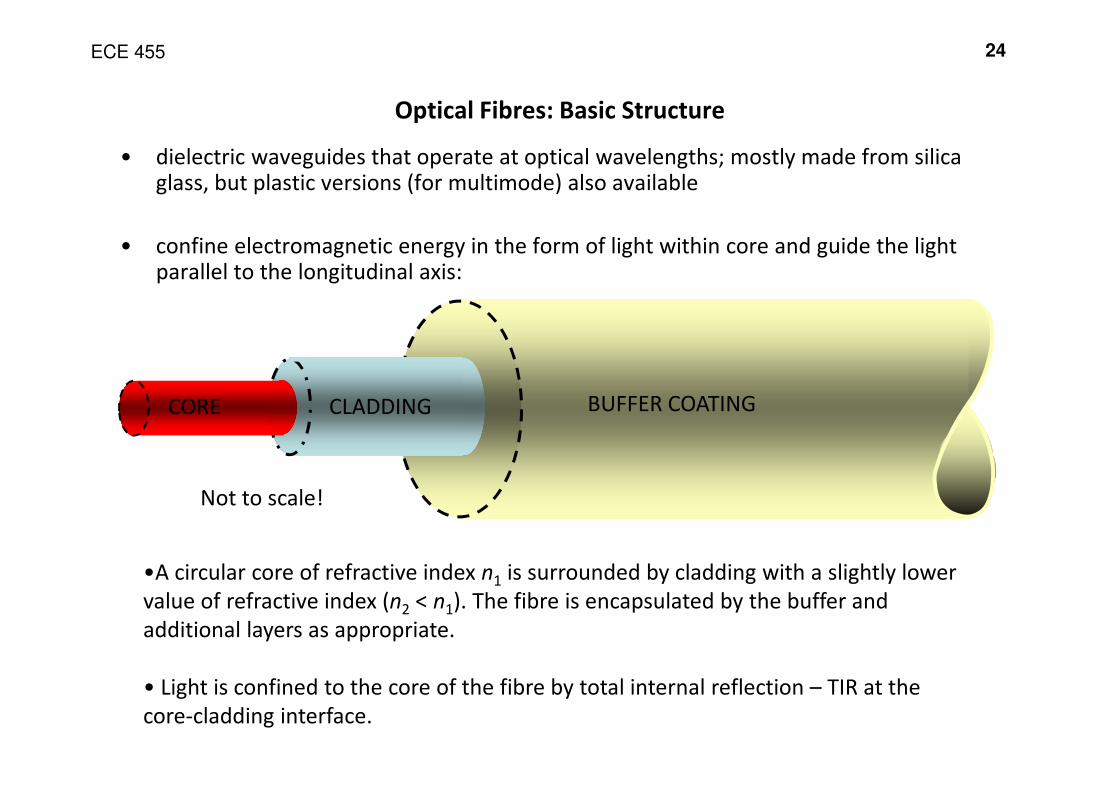
Optical Fibres: Basic Structure
•A circular core of refractive index n1 is surrounded by cladding with a slightly lower
value of refractive index (n2 < n1). The fibre is encapsulated by the buffer and
additional layers as appropriate.
• Light is confined to the core of the fibre by total internal reflection – TIR at the
core-cladding interface.
CORE CLADDING BUFFER COATING
Not to scale!
• dielectric waveguides that operate at optical wavelengths; mostly made from silica glass, but plastic versions (for multimode) also available
• confine electromagnetic energy in the form of light within core and guide the light parallel to the longitudinal axis:
ECE 455 25
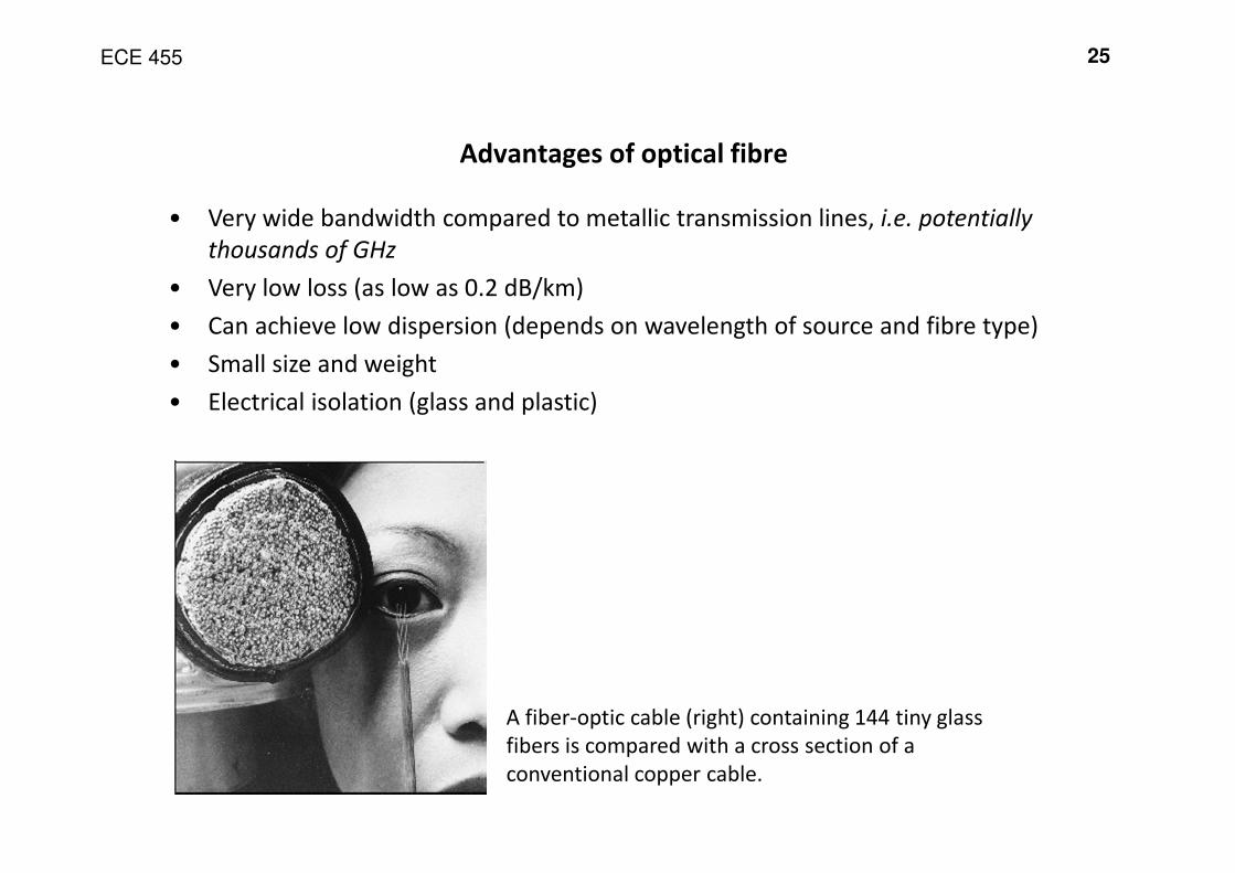
Advantages of optical fibre
• Very wide bandwidth compared to metallic transmission lines, i.e. potentially
thousands of GHz
• Very low loss (as low as 0.2 dB/km)
• Can achieve low dispersion (depends on wavelength of source and fibre type)
• Small size and weight
• Electrical isolation (glass and plastic)
A fiber-optic cable (right) containing 144 tiny glass
fibers is compared with a cross section of a
conventional copper cable.
ECE 455 26
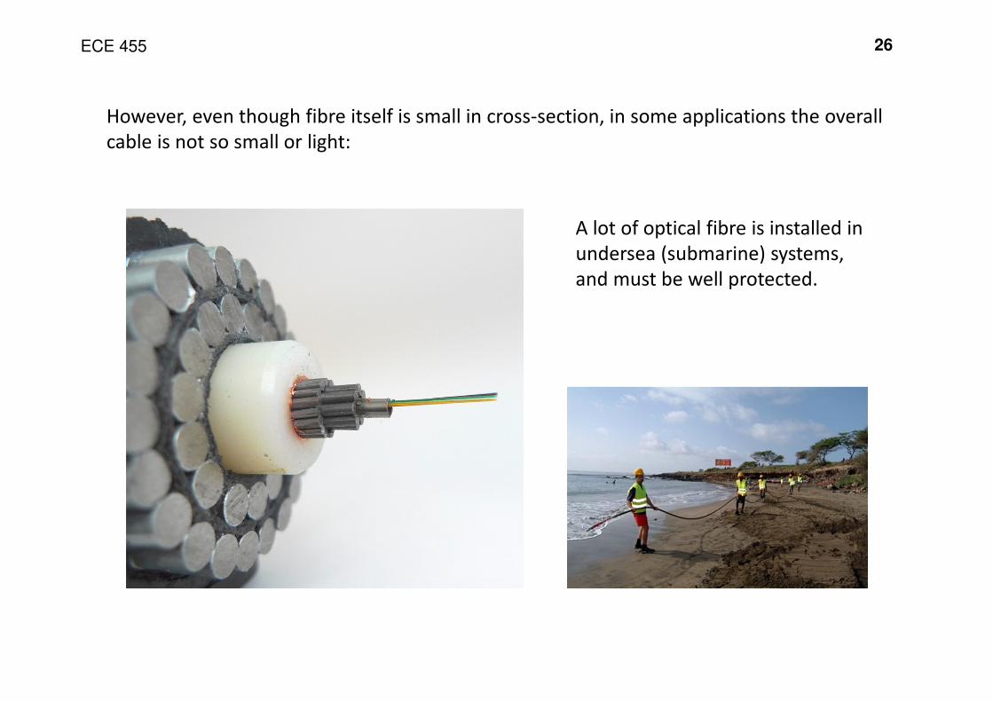
However, even though fibre itself is small in cross-section, in some applications the overall
cable is not so small or light:
A lot of optical fibre is installed in
undersea (submarine) systems,
and must be well protected.
ECE 455 27
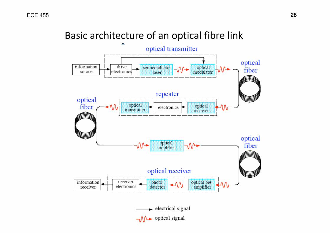
The basic ingredients of a classical communications link include:
• coherent oscillator (i.e. laser)
• mixer (e.g. directly modulated laser or modulator)
• envelope detector (e.g. photodiode)
However, there are other components (analogous to electronic
components) that are also used in optical communications:
• amplifiers (Erbium-doped fibre)
• couplers, combiners and splitters
• wavelength selective components – filters, multiplexers
• isolators and circulators
ECE 455 28
Basic architecture of an optical fibre link
ECE 455 29
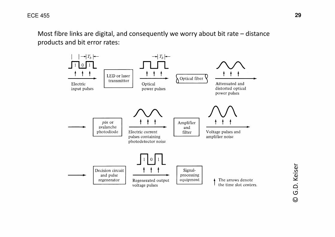
Most fibre links are digital, and consequently we worry about bit rate – distance
products and bit error rates:
© G
.D.
Ke
ise
r
ECE 455 30
Figures of merit
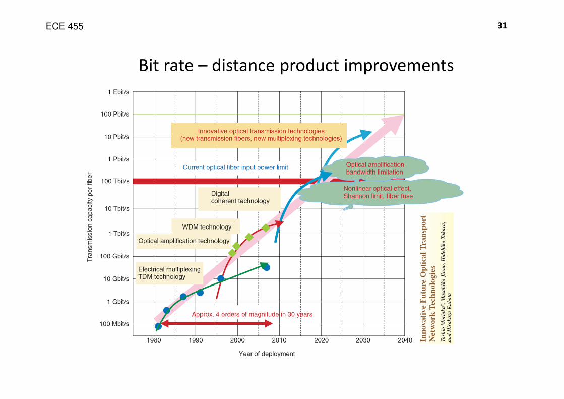
• The designers of a long distance high-bit rate fibre link have a number of
objectives.
• One is to achieve as high a bit rate as possible.
• However, it is also important to maximise the distance between optical amplifiers
or repeaters (i.e. the repeater spacing).
• The two figures are multiplied to give a key figure of merit used to assess link
performance:
Bit-rate - repeater spacing product (bits/s - km)
ECE 455 31
Bit rate – distance product improvements