ECE 331 – Digital Systems Design Sequential Logic Circuits: FSM Design (Lecture #20)
27
ECE 331 – Digital Systems Design Sequential Logic Circuits: FSM Design (Lecture #20)
-
Upload
nickolas-lawrence -
Category
Documents
-
view
227 -
download
0
Transcript of ECE 331 – Digital Systems Design Sequential Logic Circuits: FSM Design (Lecture #20)

ECE 331 – Digital Systems Design
Sequential Logic Circuits:
FSM Design
(Lecture #20)

ECE 331 - Digital Systems Design 2
FSM Design: Procedure• Understand specifications
• Derive state diagram
• Create state table
• Perform state minimization (if necessary)
• Encode states (state assignment)
• Create state-assigned table
• Select type of Flip-Flop to use
• Determine Flip-Flop input equations and FSM output equation(s)
• Draw logic diagram

ECE 331 - Digital Systems Design 3
Moore Machines
FSM Design

ECE 331 - Digital Systems Design 4
Example:
Design a FSM that detects a sequence of three or more consecutive ones on an input bit stream.
The FSM should output a 1 when the sequence is detected, and a 0 otherwise.
A circuit that detects the occurrence of a particular pattern on its input is referred to as a sequence detector.
FSM Design (Moore)

ECE 331 - Digital Systems Design 5
FSM Design: Example (Moore)
Input: 0 1 1 1 0 1 0 1 1 0 1 1 1 0 1 …
Output: 0 0 0 1 0 0 0 0 0 0 0 0 1 0 0 …

ECE 331 - Digital Systems Design 6
FSM Design: Example (Moore)
StateDiagram

ECE 331 - Digital Systems Design 7
FSM Design: Example (Moore)
QA
QB
QA+ Q
B+
State Table

ECE 331 - Digital Systems Design 8
FSM Design: Example (Moore)
The choice of Flip-Flop determines the complexity of the combinational logic required in the design of the state machine.
Each type of Flip-Flop has a unique characteristic equation.
SR Flip-Flop
Q+ = S + R'.Q
D Flip-Flop
Q+ = D
JK Flip-Flop
Q+ = J.Q' + K'.Q
T Flip-Flop
Q+ = T '.Q + T.Q'

ECE 331 - Digital Systems Design 9
Synthesis using D Flip-Flops
(Q+ = D)
FSM Design (Moore)

ECE 331 - Digital Systems Design 10
FSM Design: Example (Moore)
Flip-Flop Input
DA D
B
Q+ = Dnext state flip-flop input
QA
QB
QA+ Q
B+

ECE 331 - Digital Systems Design 11
FSM Design: Example (Moore)

ECE 331 - Digital Systems Design 12
FSM Design: Example (Moore)
QA
QB
Q'B
ECE 331 - Digital Systems Design 13
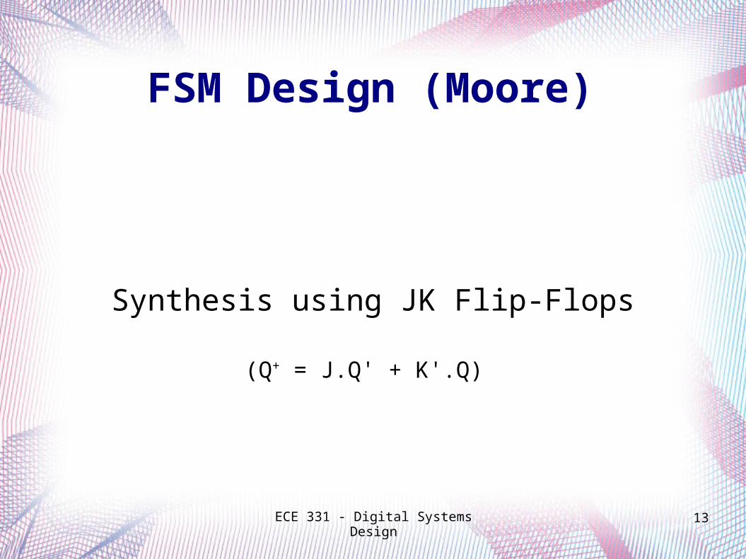
Synthesis using JK Flip-Flops
(Q+ = J.Q' + K'.Q)
FSM Design (Moore)
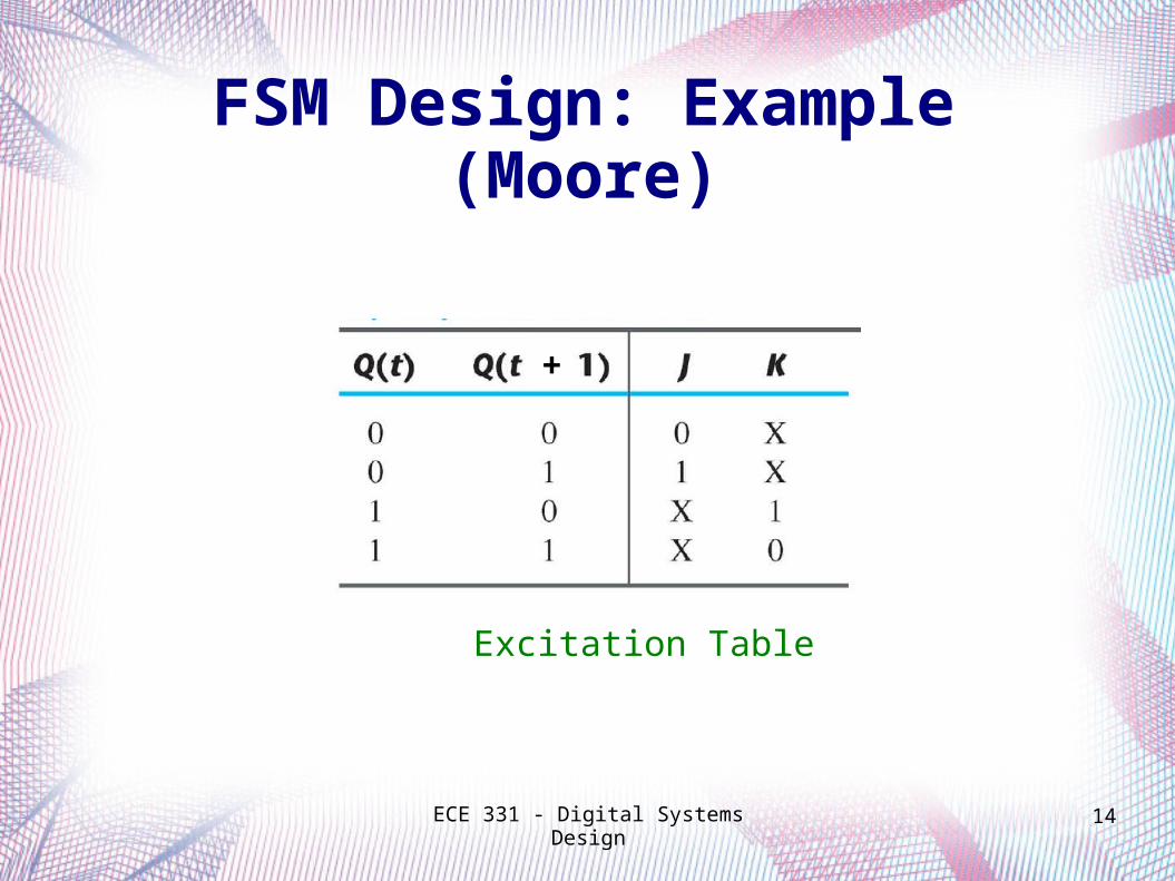
ECE 331 - Digital Systems Design 14
FSM Design: Example (Moore)
+
Excitation Table

ECE 331 - Digital Systems Design 15
FSM Design: Example (Moore)
Q+ = J.Q' + K'.Qnext state flip-flop inputs
QA
QB
QA+ Q
B+
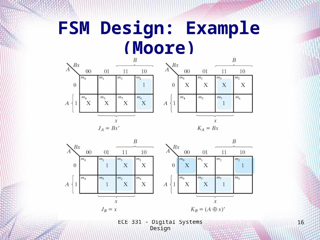
ECE 331 - Digital Systems Design 16
FSM Design: Example (Moore)

ECE 331 - Digital Systems Design 17
FSM Design: Example (Moore)
QA
QB
Q'B
Q'A

ECE 331 - Digital Systems Design 18
Example:
Design a Finite State Machine (FSM) that meets the following specifications:
This is another example of a sequence detector.
1. The circuit has one input, w, and one output, z.
2. All changes in the circuit occur on the positive edge of the clock.
3. The output z is equal to 1 if the pattern 101 is detected on the input w. Otherwise, the value of z is equal to 0. Overlapping sequences should not be detected.
FSM Design (Moore)

ECE 331 - Digital Systems Design 19
FSM Design: Example (Moore)
Input (w): 0 0 0 1 0 1 0 1 1 0 1 1 0 1 1 …
Output (z): 0 0 0 0 0 1 0 0 0 0 1 0 0 1 0 …

ECE 331 - Digital Systems Design 20
FSM Design: Example (Moore)Start State
End State
StateDiagram

ECE 331 - Digital Systems Design 21
Example:
Design a Finite State Machine (FSM) that meets the following specifications:
This is another example of a sequence detector.
1. The circuit has one input, w, and one output, z.
2. All changes in the circuit occur on the positive edge of the clock.
3. The output z is equal to 1 if the pattern 101 is detected on the input w. Otherwise, the value of z is equal to 0. Overlapping sequences should be detected.
FSM Design (Moore)

ECE 331 - Digital Systems Design 22
FSM Design: Example (Moore)
Input (w): 0 0 0 1 0 1 0 1 1 0 1 1 0 1 1 …
Output (z): 0 0 0 0 0 1 0 1 0 0 1 0 0 1 0 …
ECE 331 - Digital Systems Design 23
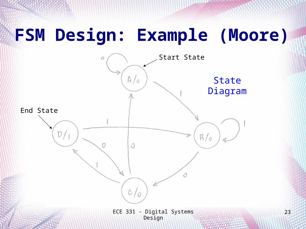
FSM Design: Example (Moore)Start State
End State
StateDiagram

ECE 331 - Digital Systems Design 24
Example:
Design a Finite State Machine (FSM) that meets the following specifications:
This is example of a sequence detector that can detect 2 sequences.
1. The circuit has one input, w, and one output, z.
2. All changes in the circuit occur on the positive edge of the clock.
3. The output z is equal to 1 if the pattern 110 or the pattern 010 is detected on the input w. Otherwise, the value of z is equal to 0. Overlapping sequences should be detected.
FSM Design (Moore)

ECE 331 - Digital Systems Design 25
FSM Design: Example (Moore)
Input (w): 0 1 0 0 1 1 0 1 0 1 1 1 0 1 1 …
Output (z): 0 0 1 0 0 0 1 0 1 0 0 0 1 0 0 …

ECE 331 - Digital Systems Design 26
FSM Design: Example (Moore)
StateDiagram

ECE 331 - Digital Systems Design 27
Acknowledgments
The slides used in this lecture were taken, with permission, from those provided by Pearson Prentice Hall for
Digital Design (4th Edition).
They are the property of and are copyrighted by Pearson Education.