Eccentric Screw Pumps in Block-Design Series AEB4H Design IE
12
Material pairing and design are adapted to the respective ope- rating conditions. For further data, refer to pages 4, 5. The stuffing box or mechanical seal housings of the various shaft sealing types are interchangeable within one size. The various mechanical seal housing parts form a modular con- struction system and, in case of conversion to a different mechanical seal design, can be easily combined with one another. Installation spaces for mechanical seals according to DIN 24 960 (except for double mechanical seal). For further information, refer to pages 4, 5, 6 and 7. Technical data Deliveries, admissible speed ranges and required drive powers are to be taken from the performance graph on page 3 and/or the separate individual characteristic curves. AEB4H Delivery Q l/min up to 200 Temperature of fluid pumped t °C ➀ up to 100 Delivery pressure ∆p bar up to 24 Pump outlet pressure p d bar ➂ up to 25 Attainable underpressure p s bar ➁ up to 0,95 Viscosity mPa · s ➁ up to 270.000 Admissible solids content Vol % ➁ up to 60 The mentioned performance data are to be considered as a product and performance abstract only. The particular operat- ing limits can be taken from the quotation or order acknow- ledgement. Max. admissible grain sizes and fiber length Size 12 25 50 max. grain size mm 2 2,5 3 max. fiber length mm 35 42 42 Increasing solids content and increasing grain size require a reduction of the pump speed: ➀ depending on the fluid to be pumped and the elastomers employed. ➁ depending on the pump size/design, speed and fluid to be pumped. ➂ depending on the direction of rotation, inlet pressure. Bearings The driving/joint shaft are situated in the reinforced bearings of the electric motors, gear motors or control gear which also absorb the generated axial forces. As all drives are only supplied with reinforced bearings it must be assured that the assigned pumps can be run at full capa- city within their permissible application limits. ALLWEILER a ALLWEILER a 1 Eccentric Screw Pumps in Block-Design Series AEB4H Design IE Application For handling liquid to highly viscous, neutral or aggressive, uncontaminated or abrasive liquids, liquids containing gases or which tend to froth, also containing fibers and solid matter. In waste water and waste water treatment engineering, chemi- cal and petrochemical industry, paper and cellulose industry, soap and fats industry, paint and lacquer industry, food and beverage industry, plastics industry, ceramics industry, agricul- ture, sugar industry and in shipbuilding. Operating Self-priming, four-stage, rotary positive displacement pump. Conveying elements are the rotating eccentric screw (rotor) and the fixed stator. In the cross-sectional plane, both are in contact with one another at two points forming two sealing lines along the length of the conveying elements. The contents of the sealed chambers which are formed as the rotor turns, are displaced axially and with complete continuity from the suc- tion to the delivery end of the pump. Despite rotor rotation, there is no turbulence. The constant chamber volume prevents squeezing, thus ensuring an extremely gentle low-pulsating delivery. Design features The pump and drive are held together by the bearing bracket to form a modular unit. By means of external casing connecting screws (clamping screws), the pressure casing, stator and suction casing are interconnected. The suction casings are designed particularly favorable to flow. The pump sizes 50 is supplied in cast iron and is provided with staggered holes for cleaning. The stator vul- canized into a tube is provided with external collars vulcanized to it on both sides, reliably sealing towards the suction casing and protecting the stator shell from corrosion. The exchangeable shaft sealing housing or mechanical seal housing (subsequent conversion to another sealing variant is possible) are arranged between the suction casing and bearing bracket. The torque of the drive is transmitted over the driving shaft and the joint shaft onto the rotor. On both sides, the joint shaft ends in liquid-tight encapsulated bolt joints, which are of particularly simple and sturdy design and easily absorb the eccentric move- ment of the rotor. Shaft seal By uncooled or heated stuffing box or by uncooled or cooled maintenance-free unbalanced, single or double-acting mecha- nical seal.
Transcript of Eccentric Screw Pumps in Block-Design Series AEB4H Design IE
Material pairing and design are adapted to the respective ope-rating conditions. For further data, refer to pages 4, 5.
The stuffing box or mechanical seal housings of the variousshaft sealing types are interchangeable within one size. Thevarious mechanical seal housing parts form a modular con-struction system and, in case of conversion to a differentmechanical seal design, can be easily combined with one another.
Installation spaces for mechanical seals according toDIN 24 960 (except for double mechanical seal).
For further information, refer to pages 4, 5, 6 and 7.
Technical dataDeliveries, admissible speed ranges and required drive powersare to be taken from the performance graph on page 3 and/orthe separate individual characteristic curves.
AEB4H
Delivery Q l/min up to 200
Temperature of fluid pumped t °C ➀ up to 100
Delivery pressure ∆p bar up to 24
Pump outlet pressure pd bar ➂ up to 25
Attainable underpressure ps bar ➁ up to 0,95
Viscosity mPa · s ➁ up to 270.000
Admissible solids content Vol % ➁ up to 60
The mentioned performance data are to be considered as aproduct and performance abstract only. The particular operat-ing limits can be taken from the quotation or order acknow-ledgement.
Max. admissible grain sizes and fiber length
Size 12 25 50
max. grain size mm 2 2,5 3
max. fiber length mm 35 42 42
Increasing solids content and increasing grain size require a reduction of the pumpspeed:
➀ depending on the fluid to be pumped and the elastomers employed.➁ depending on the pump size/design, speed and fluid to be pumped.➂ depending on the direction of rotation, inlet pressure.
BearingsThe driving/joint shaft are situated in the reinforced bearings of the electric motors, gear motors or control gear which alsoabsorb the generated axial forces.
As all drives are only supplied with reinforced bearings it mustbe assured that the assigned pumps can be run at full capa-city within their permissible application limits.
ALLWEILER aALLWEILER a
1
Eccentric Screw Pumpsin Block-Design
Series AEB4HDesign IE
ApplicationFor handling liquid to highly viscous, neutral or aggressive,uncontaminated or abrasive liquids, liquids containing gases orwhich tend to froth, also containing fibers and solid matter.
In waste water and waste water treatment engineering, chemi-cal and petrochemical industry, paper and cellulose industry,soap and fats industry, paint and lacquer industry, food andbeverage industry, plastics industry, ceramics industry, agricul-ture, sugar industry and in shipbuilding.
OperatingSelf-priming, four-stage, rotary positive displacement pump.Conveying elements are the rotating eccentric screw (rotor)and the fixed stator. In the cross-sectional plane, both are incontact with one another at two points forming two sealinglines along the length of the conveying elements. The contentsof the sealed chambers which are formed as the rotor turns, are displaced axially and with complete continuity from the suc-tion to the delivery end of the pump. Despite rotor rotation,there is no turbulence. The constant chamber volume preventssqueezing, thus ensuring an extremely gentle low-pulsatingdelivery.
Design featuresThe pump and drive are held together by the bearing bracket toform a modular unit.
By means of external casing connecting screws (clamping screws), the pressure casing, stator and suction casing areinterconnected. The suction casings are designed particularlyfavorable to flow. The pump sizes 50 is supplied in cast iron andis provided with staggered holes for cleaning. The stator vul-canized into a tube is provided with external collars vulcanizedto it on both sides, reliably sealing towards the suction casingand protecting the stator shell from corrosion.
The exchangeable shaft sealing housing or mechanical sealhousing (subsequent conversion to another sealing variant ispossible) are arranged between the suction casing and bearingbracket.
The torque of the drive is transmitted over the driving shaft andthe joint shaft onto the rotor. On both sides, the joint shaft endsin liquid-tight encapsulated bolt joints, which are of particularlysimple and sturdy design and easily absorb the eccentric move-ment of the rotor.
Shaft sealBy uncooled or heated stuffing box or by uncooled or cooledmaintenance-free unbalanced, single or double-acting mecha-nical seal.

ALLWEILER aSeries AEB4HDesign IE
2
DriveThe drive can be provided by non-explosion-proof or explosion-proof three-phase motors, gear motors or control gear. Fordrive options see page 12. For technical data and dimensions,please refer to the separate sales documentation, data sheet19-00-0000-111-3.
A considerable advantage is the fact that within a pump sizethe connection dimensions for all drive types are the same.This facillitates a later change to a different drive type or size.
InstallationAE pumps may be installed horizontally or vertically. In case of vertical arrangement, “shaft shank downwards” is not admis-sible.
Exchangeability of componentsThe components of all eccentric screw pumps are of a modulardesign. This allows a simple and cost-effective spare parts management even if different series and designs of pumps areused.
3
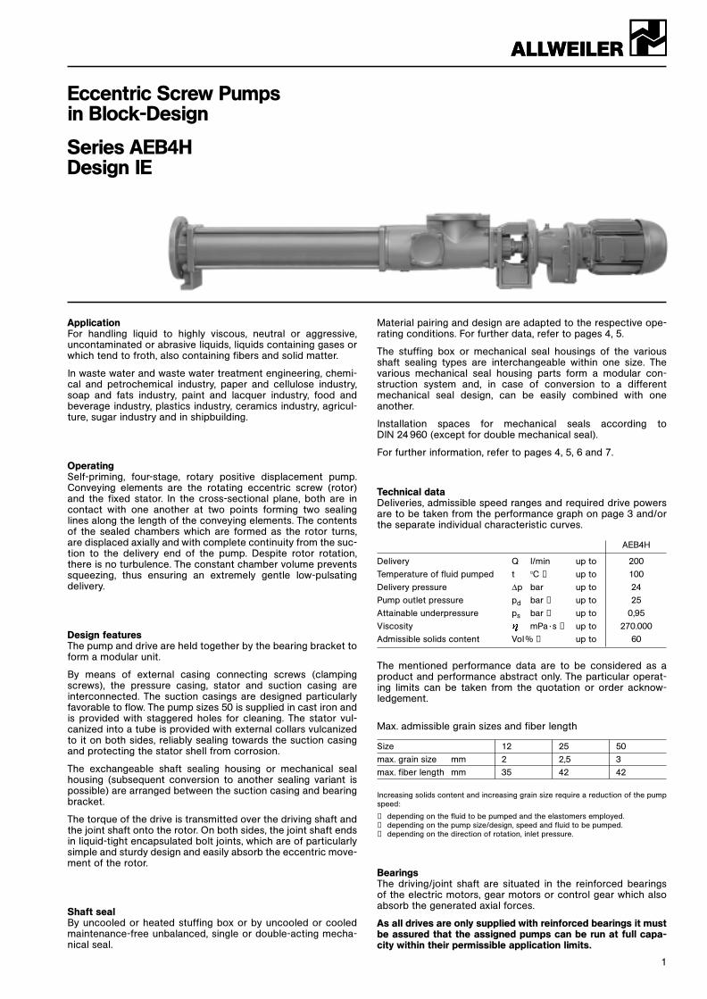
Performance graphFor a rough selection of the pump size and speed as a function of the requested delivery and kind of fluid to be pumped. Vg„m“ = available, mean sliding speed of the rotor in the stator.
Del
iver
y Q
th[l
/min
] at
∆p
= 0
bar
Speed n [1/min]
Pum
p s
ize
extremely viscous high viscous viscous liquid
relatively little non-very abrasive abrasive abrasive abrasive
Vg„m“ [
m/s]
ALLWEILER aSeries AEB4HDesign IE
Sizes of the series AEB4H. Data on the performance range not covered by AEB series are to be taken from the last page of this brochure and/or the individual brochures of the other series.For exact performance data, please refer to the individual characteristics.

44
ALLWEILER aSeries AEB4HDesign IE
Explanations to the type code:
Position Designation Designin typecode
1 Product ALLWEILER eccentric screw pumps
2 Number of 4 = four-stage up to delivery pressure ∆p 24 barstages
3 Mechanical H = rated for delivery presure ∆p 24 barsystem
4 Size Possible sizes: 12, 25, 50.The numbers indicate the theoretic delivery in l/min with n = 400 1/min and ∆p = 0 bar
5 Design IE = Industrial design with external bearing
6 Bearing design 0 = external bearing in drive unit
7 Suction and 1 = DIN flanges according to dimensional sheet, pages 9 and 10outlet branch 3 = ANSI flangesdesign X = Suction and/or delivery branch of special design
8 Branch position 1, 2, 3, 4 – For arrangement please refer to the representation, page 9. Arrangement 3 is not possible for size 12.
9 Shaft seal type P = Stuffing box or other non-mechanical shaft sealG = Mechanical seal (mechanical shaft seal)
0 Shaft design 0 = Shaft without shaft sleeve
ß Shaft seal Stuffing boxesdesign P01 = Stuffing box of normal design (without sealing chamber ring/without flushing ring)
P02 = Stuffing box with flushing ringP03 = Stuffing box with internal sealing chamber ringP04 = Stuffing box with external sealing chamber ringP0X = Non-mechanical shaft seal of special design
Type codeMaterial designGeometric designType series
1 2 3 4 5 6 7 8 9 0 ß “ „ ” ¿ ¸ q w e r
AEB 4 H 25 – IE / 0 3 2 P 0 1 NC 1 1 2 V V 6230AEB 4 H 50 – IE / 0 1 1 G 0 D D 1 CS 4 2 3 P P 6ATTV/2P
ProductNumber of stagesMechanical systemSizeType of constructionBearing designSuction and outlet branch designBranch positionShaft seal kindShaft designShaft seal designDouble shellDouble shell designDesign variantsSuction/delivery casing, in contact with liquid, materialsDriving shaft, joint shaft, in contact with liquid, materialsRotor materials Stator materialsJoint sleeve materialsShaft seal materials
6ATTV/2P
Sliding material pairing, product sideSprings and construction materials
Example: double-acting mechanical seal Auxiliary gaskets, product-sideSliding material pairing, atmosphere-sideAuxiliary gaskets, atmosphere-side
5
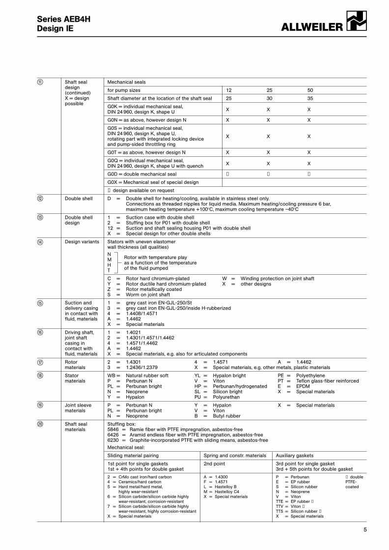
ß Mechanical seals
for pump sizes 12 25 50
Shaft diameter at the location of the shaft seal 25 30 35
G0K = individual mechanical seal, DIN 24 960, design K, shape U X X X
G0N = as above, however design N X X X
G0S = individual mechanical seal, DIN 24 960, design K, shape U, rotating part with integrated locking deviceand pump-sided throttling ring
X X X
G0T = as above, however design N X X X
G0Q = individual mechanical seal, DIN 24 960, design K, shape U with quench X X X
G0D = double mechanical seal ➀ ➀ ➀
G0X = Mechanical seal of special design
➀ design available on request
“ Double shell D = Double shell for heating/cooling, available in stainless steel only.Connections as threaded nipples for liquid media. Maximum heating/cooling pressure 6 bar, maximum heating temperature +100°C, maximum cooling temperature –40°C
„ Double shell 1 = Suction case with double shelldesign 2 = Stuffing box for P01 with double shell
12 = Suction and shaft sealing housing P01 with double shellX = Special design for other double shells
” Design variants Stators with uneven elastomerwall thickness (all qualities)
NM Rotor with temperature play
H as a function of the temperature
T of the fluid pumped
C = Rotor hard chromium-plated W = Winding protection on joint shaftY = Rotor ductile hard chromium-plated X = other designsZ = Rotor metallically coatedS = Worm on joint shaft
¿ Suction and 1 = grey cast iron EN-GJL-250/Stdelivery casing 3 = grey cast iron EN-GJL-250/inside H-rubberizedin contact with 4 = 1.4408/1.4571fluid, materials A = 1.4462
X = Special materials
¸ Driving shaft, 1 = 1.4021joint shaft 2 = 1.4301/1.4571/1.4462casing in 4 = 1.4571/1.4462contact with A = 1.4462fluid, materials X = Special materials, e.g. also for articulated components
q Rotor 2 = 1.4301 4 = 1.4571 A = 1.4462materials 3 = 1.2436/1.2379 X = Special materials, e.g. other metals, plastic materials
w Stator WB = Natural rubber soft YL = Hypalon bright PE = Polyethylenematerials P = Perbunan N V = Viton PT = Teflon glass-fiber reinforced
PL = Perbunan bright HP = Perbunan/hydrogenated E = EPDMN = Neoprene SL = Silicon bright X = Special materialsY = Hypalon PU = Polyurethan
e Joint sleeve P = Perbunan N Y = Hypalon X = Special materialsmaterials PL = Perbunan bright V = Viton
N = Neoprene B = Butyl rubber
r Shaft seal Stuffing box:materials 5846 = Ramie fiber with PTFE impregnation, asbestos-free
6426 = Aramid endless fiber with PTFE impregnation, asbestos-free6230 = Graphite-incorporated PTFE with sliding means, asbestos-free
Mechanical seal:
Sliding material pairing Spring and constr. materials Auxiliary gaskets
1st point for single gaskets 2nd point 3rd point for single gasket1st + 4th points for double gasket 3rd + 5th points for double gasket
2 = CrMo cast iron/hard carbon A = 1.4300 P = Perbunan ➀ double 4 = Ceramics/hard carbon F = 1.4571 E = EP rubber PTFE-5 = Hard metal/hard metal, L = Hastelloy B S = Silicon rubber coated
highly wear-resistant M = Hastelloy C4 N = Neoprene6 = Silicon carbide/silicon carbide highly X = Special materials V = Viton
wear-resistant, corrosion-resistant TTE = EP rubber ➀7 = Silicon carbide/silicon carbide highly TTV = Viton ➀
wear-resistant, highly corrosion-resistant TTS = Silicon rubber ➀X = Special materials X = Special materials
Shaft sealdesign(continued)X = design possible
ALLWEILER aSeries AEB4HDesign IE
6
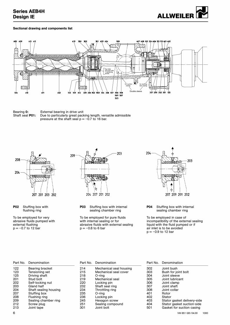
Sectional drawing and components list
Bearing 0: External bearing in drive unitShaft seal P01: Due to particularly great packing length, versatile admissible
pressure at the shaft seal p = –0.7 to 16 bar.
P02 Stuffing box with flushing ring
To be employed for very abrasive fluids pumped with external flushing p = –0.7 to 12 bar
P03 Stuffing box with internal sealing chamber ring
To be employed for pure fluids with internal sealing or for abrasive fluids with external sealing p = –0.8 to 6 bar
P04 Stuffing box with internal sealing chamber ring
To be employed in case ofincompatibility of the external sealingliquid with the fluid pumped or if air inlet is to be avoided p = –0.9 to 12 bar
Part No. Denomination
122 Bearing bracket123 Tensioning set125 Driving shaft201 Stud bolt202 Self-locking nut203 Gland half204 Shaft sealing housing207 Stuffing box208 Flushing ring209 Sealing chamber ring212 Screw plug213 Joint tape
Part No. Denomination
214 Mechanical seal housing215 Mechanical seal cover218 O-ring219 Mechanical seal220 Locking pin232 Shaft seal ring234 Throttling ring235 O-ring236 Locking pin245 Hexagon screw251 Sealing compound301 Joint bolt
Part No. Denomination
302 Joint bush303 Bush for joint bolt304 Joint sleeve305 Joint lubricant306 Joint clamp307 Joint shaft308 Joint collar401 Rotor402 Stator403 Stator gasket delivery-side404 Stator gasket suction-side501 Gasket for suction casing
VM 851 GB / 04.00 1000
ALLWEILER aSeries AEB4HDesign IE
Part 304secured with1 centering
for suctioncasing
for stuffingbox casing
Double sleeve
stroke
7
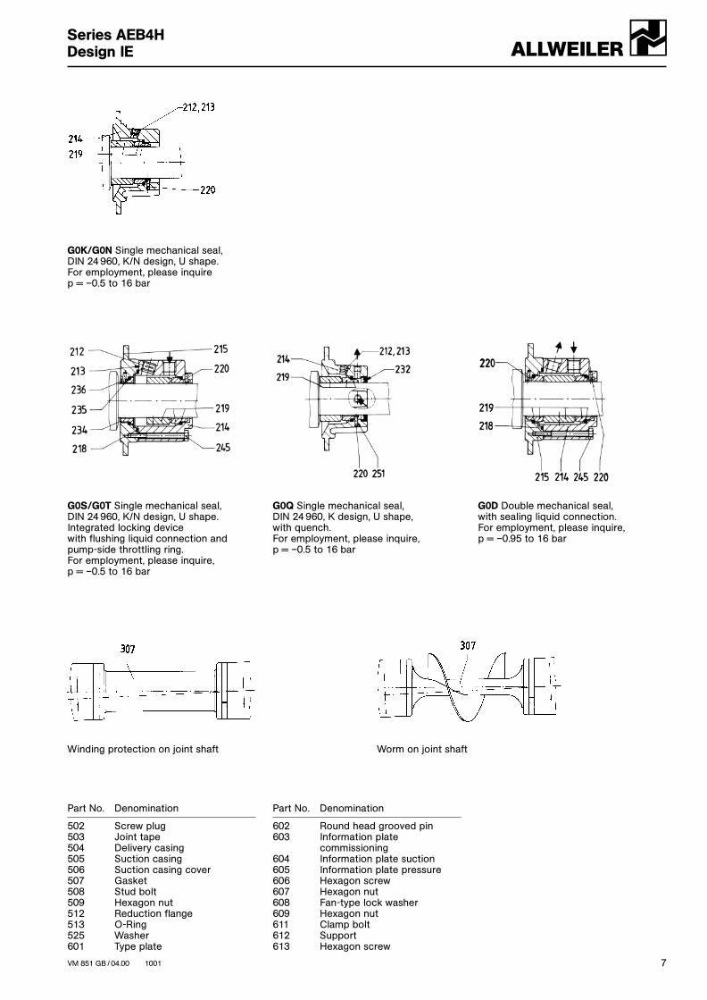
G0K/G0N Single mechanical seal,DIN 24 960, K/N design, U shape. For employment, please inquire p = –0.5 to 16 bar
G0S/G0T Single mechanical seal,DIN 24 960, K/N design, U shape.Integrated locking device with flushing liquid connection and pump-side throttling ring. For employment, please inquire, p = –0.5 to 16 bar
G0Q Single mechanical seal,DIN 24 960, K design, U shape, with quench.For employment, please inquire,p = –0.5 to 16 bar
G0D Double mechanical seal,with sealing liquid connection.For employment, please inquire,p = –0.95 to 16 bar
Part No. Denomination
502 Screw plug503 Joint tape504 Delivery casing505 Suction casing506 Suction casing cover507 Gasket508 Stud bolt509 Hexagon nut512 Reduction flange513 O-Ring525 Washer601 Type plate
Part No. Denomination
602 Round head grooved pin603 Information plate
commissioning604 Information plate suction605 Information plate pressure606 Hexagon screw607 Hexagon nut608 Fan-type lock washer609 Hexagon nut611 Clamp bolt612 Support613 Hexagon screw
VM 851 GB / 04.00 1001
ALLWEILER aSeries AEB4HDesign IE
Winding protection on joint shaft Worm on joint shaft

Pump dimensions, auxiliary connections, possible branch positions, weights
8
Dimensions in mm, nominal width Sense of rotation:of ANSI flanges (DN) in inches. counter-clockwise as seen from driving sideSubject to alteration. with DN1 = outlet branch, DN2 = suction branch
Series Pump dimensions Max.Size ➀ mass
b c1 c3 e f h m1 m3 n1 n3 o q s L kg
AEB4H 12-IE 668 8 10 75 95 90 42 84 11 19 162 360 9 Rp 3/8
AEB4H 25-IE 814 8 10 85 105 100 42 93 11 19 185 465 9 Rp 3/8
AEB4H 50-IE 1032 13 13 100 125 125 48 106 13 25 220 605 11,5 Rp 1/2
Series Connection dimensions/Flange dimensions for outlet branchSize
Flanges DIN 2501, PN 25 ➂ Flanges ANSI B16.5 RF, Class 300 ➃➄ ➄ ➄ ➄ ➄ ➄
DN1 d1 k k1 p w z DN1 d1 k k1 p w z
AEB4H 12-IE 32 18 775 100 613 39 4 11/4 19 797 98,4 635 61 4
AEB4H 25-IE 40 18 938 110 753 47 4 11/2 22,2 960 114,3 775 69 4
AEB4H 50-IE 50 18 1164 125 944 48 4 2 19 1185,5 127 965,5 69,5 8
Series Connection dimensions/Flange dimensions for suction branchSize
Flanges DIN 2501, PN 16 ➅ Flanges ANSI B16.1, Class 125 ➃ Flanges ANSI B16.5, Class 150 ➃➄ ➄ ➄
DN2 d1 g k1 z DN2 d1 g k1 z DN2 d1 g k1 z
AEB4H 12-IE 40 18 175 110 4 11/2 15,9 172 98,4 4 11/2 15,9 175 98,4 4
AEB4H 25-IE 50 18 190 125 4 2 19 186 120,6 4 2 19 190 120,6 4
AEB4H 50-IE 65 18 230 145 4 21/2 19 229 139,7 4 21/2 19 234 139,7 4
➀ Stator dismantling dimension ➄ for rubber-coating + 3 mm➂ Sealing surface DIN 2526 shape C ➅ up to DN 100 sealing surface DIN 2526 shape C, machined as shape A ➃ Sealing surface: stock finish from DN 125 sealing surface DIN 2526 shape A
Possible branch positions asseem from the drive
➁ not for size 12
ALLWEILER aSeries AEB4HDesign IE
s
n3
m3
b
n1
s c3
q 1
h
c1
DN2
o
DN
1
k
p
L
w
m1
g
g-h
f
e
g-h g-h
VM 851 GB / 04.00 2000
k1 DN
1D
N2
Arrangement
4 holes
Arrangement
8 holes
z = number of holes
d1

9VM 851 GB / 04.00 2001
ALLWEILER aSeries AEB4HDesign IE
Arrangement of auxiliary connections for shaft seals
P02 with flushing rod G0S/G0T with flushing connection
P03 with internal sealing chamber ring G0Q with quench connection
P04 with external sealing chamber ring G0D with sealing connection
S1 S1
S1
x 1
t1
u1
S4 S4
S4
x 4
u4
S6 S7x 7 x 6
u6t7
u7
S7
S6
S7
S7
S6
S6
x 3
u3
S3
S3
30°
S2 S2 x 2
t2
u2
S5 S5
S5
x
u5
5
Series Connection dimensions for auxiliary connections for shaft sealsSize
PO2 with flushing ring PO3 with internal sealing PO4 with external sealingchamber ring chamber ring
S1 ➆ u1 x1 t1 S2 ➆ u2 x2 t2 S3 ➆ u3 x3
AEB4H 12-IE M 8 x 1 84 28 42° M 8 x 1 77 30 20° M 8 x 1 69 30,5
AEB4H 25-IE M 8 x 1 93 31,5 40° M 8 x 1 87 32 20° M 8 x 1 78,5 33,5
AEB4H 50-IE Rp 1/8 104,5 38 42° Rp 1/8 97 40 17° Rp 1/8 85 39,5
Series Connection dimensions for auxiliary connections for shaft sealsSize
GOS/GOT with GOQ with GOD with sealing connectionflushing connection quench connection
S5 ➆ u5 x5 S4 ➆ u4 x4 S6 ➆ S7 ➆ u6 u7 x6 x7 t7
AEB4H 12-IE Rp 1/4 46,5 34 Rp 1/8 56 30,5 Rp 1/4 Rp 1/4 46,5 71,5 34 33 15°
AEB4H 25-IE Rp 1/4 55 38 Rp 1/8 63,5 30,5 Rp 1/4 Rp 1/4 55 79 38 36,5 15°
AEB4H 50-IE Rp 1/4 69,5 41,5 Rp 1/8 74 33,5 Rp 1/4 Rp 1/4 69,5 95 41,5 40 15°
➆ Threaded connection DIN 3852, shape Z
n Standard supplyN Possible supply, for these purposes, the sealing housing must be turned in case of designs P02, G0S, G0T, G0Q, G0D.
10
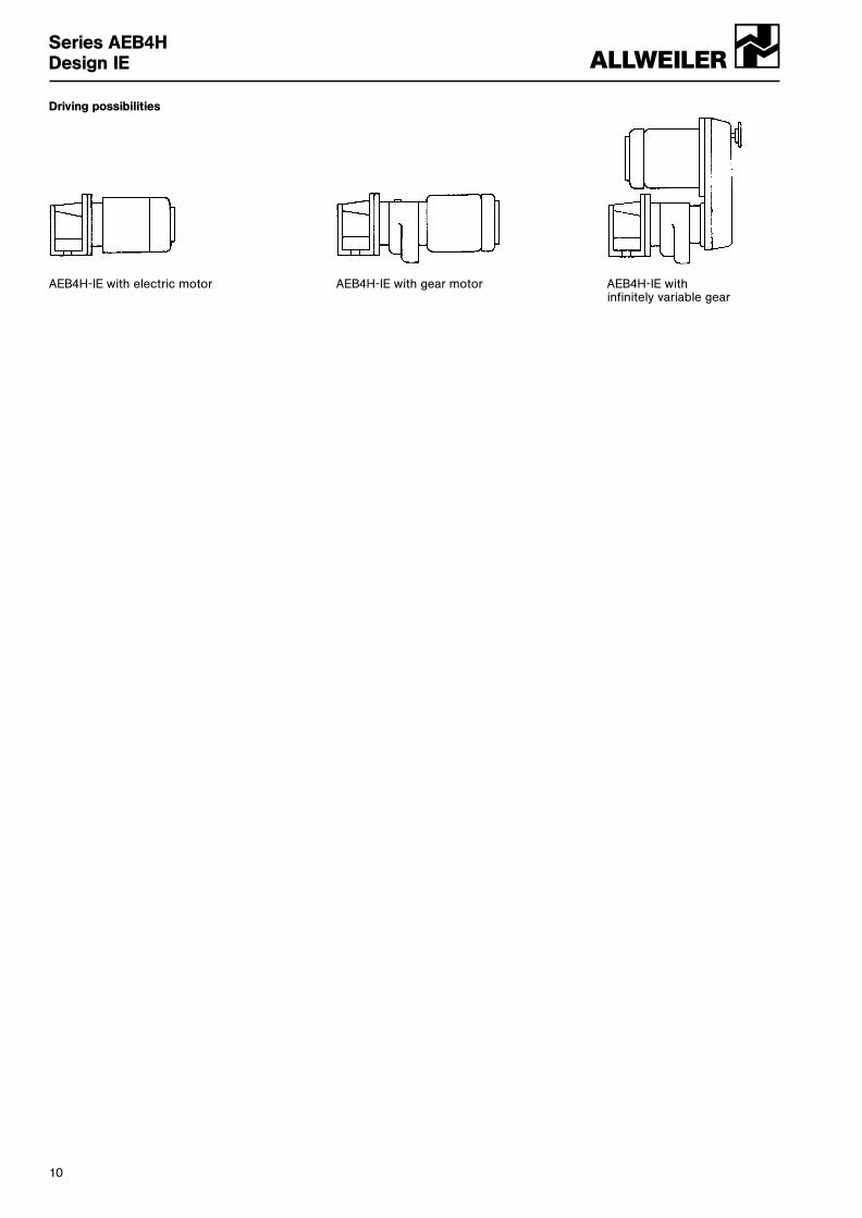
Driving possibilities
AEB4H-IE with electric motor AEB4H-IE with gear motor AEB4H-IE with infinitely variable gear
ALLWEILER aSeries AEB4HDesign IE

11
ALLWEILER aSeries AEB4HDesign IE

ALLWEILER aSeries AEB4HDesign IE
VM 851 GB / 04.00 – Ident No. 796 201
ALLWEILER aA Member of the COLFAX PUMP GROUPALLWEILER AG · Werk BottropPostfach 200123 · 46223 Bottrop Kirchhellener Ring 77-79 · 46244 Bottrop Germany Tel. +49 (0)2045 966-60 Fax +49 (0)2045 966-679E-mail: [email protected] Internet: http://www.allweiler.com
Subject to technical alterations.
Range of eccentric Series Number of Maximum output at ∆p = 0 bar Maximum Maximumscrew pumps stages del. pressure viscosity
m3/h l/min bar mPa · sAE.E-ID 1,2 450 7500 10 300.000AE.N-ID 1,2 290 4850 16 270.000AE.H-ID 2,4 174 2900 24 270.000AEB.E-IE 1,2 174 2900 6 300.000AEB.N-IE 1,2 111 1850 12 270.000AEB4H-IE 4 12 200 24 270.000AED.E-ID 1 720 12000 8 250.000AED.N-ID 2 450 7500 16 225.000AEDB.E-IE 1 258 4300 6 250.000AEDB.N-IE 2 174 2900 12 225.000AE.N...-RG 1,2,4 30 500 20 1.000.000TECFLOW 1 186 3100 4 200.000SEZP 1,2 21 350 10 1.000.000SNZP 1,2 45 750 12 1.000.000SNZBP 1,2 45 750 12 1.000.000SSP 1,2 48 800 12 150.000SSBP 1,2 48 800 12 150.000SETP ➀ 1,2 140 2350 10 300.000SETBP 1,2 40 670 10 150.000SEFBP 1 40 670 6 150.000SMP 1 40 670 6 150.000SMP2 1 5,5 92 6 11.500AFP 1 2,8 47 6 50.000ANP 2 2,5 42 12 20.000ANBP 2 2,5 42 12 20.000ASP 2 2,5 42 12 20.000ASBP 2 2,5 42 12 20.000ADP 3 0,6 10 12 20.000ADBP 3 0,6 10 12 20.000ACNP 1,2 29 480 12 150.000ACNBP 1,2 29 480 12 150.000
➀ Special versions for higher pressures available.
Peristaltic range Series Maximum output Maximum Maximumdel. pressure viscosity
m3/h l/min bar mPa · sASL 2,4 40 4 100.000ASH 60 1000 15 100.000
Macerator range Series Maximum throughput Generated delivery headm3/h m
AM ... S–1 80 at 3 % solids 3ABM ... S–1 80 at 3 % solids 3AM ... I–1 160 at 3 % solids –ABM ... I–1 80 at 3 % solids –
Accessories Pump accessories: Stator setting devices, electrical heaters, bridge breakers.Drivers: Electric motors, geared motors, variable speed transmissions, reduction gearboxes, internalcombustion engines, pneumatic and hydraulic drives.Transmission components: Couplings, V-belt transmissions, toothed belt transmissions, other typesof transmission.Base plates: Standard and special versions, wheeled trolleys, mounting flanges.Safety arrangements: Bypass lines with safety or regulating valves, systems to guard against dry running (conductive, capacitive, thermal etc.).Other accessories: Electrical, hydraulic and pneumatic control arrangements, filter systems, metering equipment, seal liquid and circulating systems for shaft seals, valves, flanges, flexible pipes.
Sta
nd: 0
5.00
GB