Eccentric Load
6
Eccentric Load A load imposed on a structural member at some point other than the centroid of the section A compressive or tensile load which does not act through the centroid of the cross section. Columns The column is one of the most familiar architectonic icons. Each of us can picture this very important space definer in our mind's eye. It can delineate, punctuate, or seperate spaces. A quick glance out most windows allows a view of at least one of them. Columns are vertical load- bearing elements which are normally loaded in compression. Time has brought many manifestations of this simple element; thick, thin, long, short, spindle shaped, squat, etc. And they have been made out of any material that has a minimal compressive strength. The transition between the column and its loading member, usually a beam of some sort, has often been of great interest to builders. The structural/functional problem is quite simple - the forces collected by the beam must be transferred from the beam to the column - and yet the solutions demonstrated a great variation. The early Egyption, Greek and Roman civilizations turned this transition zone into an articulated flourish to draw attention to the capital. In almost every case it was broader at the top and tapered to the column shaft. This not only facilitated a smooth transition for the forces, but also eased the construction and even increased the stability of of the buildings. A column either crushes (a strength falure) or it buckles (a stability failure). Both modes of failure must be considered for every column. The exact mode of failure is greatly dependent upon the way in which the column's cross-sectional area is distributed with respect to its centroid. The following simple concept must be satisfied at all times: Stress due to loading < Resistance potential of the column
-
Upload
atish-kumar -
Category
Documents
-
view
1.943 -
download
1
description
all are for civil engg
Transcript of Eccentric Load

Eccentric Load
A load imposed on a structural member at some point other than the centroid of the section
A compressive or tensile load which does not act through the centroid of the cross section.
Columns
The column is one of the most familiar architectonic icons. Each of us can picture this very
important space definer in our mind's eye. It can delineate, punctuate, or seperate spaces. A
quick glance out most windows allows a view of at least one of them. Columns are vertical load-
bearing elements which are normally loaded in compression. Time has brought many
manifestations of this simple element; thick, thin, long, short, spindle shaped, squat, etc. And
they have been made out of any material that has a minimal compressive strength.
The transition between the column and its loading member, usually a beam of some sort, has
often been of great interest to builders. The structural/functional problem is quite simple - the
forces collected by the beam must be transferred from the beam to the column - and yet the
solutions demonstrated a great variation. The early Egyption, Greek and Roman civilizations
turned this transition zone into an articulated flourish to draw attention to the capital. In
almost every case it was broader at the top and tapered to the column shaft. This not only
facilitated a smooth transition for the forces, but also eased the construction and even
increased the stability of of the buildings.
A column either crushes (a strength falure) or it buckles (a stability failure). Both modes of
failure must be considered for every column. The exact mode of failure is greatly dependent
upon the way in which the column's cross-sectional area is distributed with respect to its
centroid. The following simple concept must be satisfied at all times:
Stress due to loading < Resistance potential of the column
This states that the stress within the column due to all of the applied loads must be less than
the allowable stress of the material. This is a logical statement that is the essence of the
structural analysis of a column. The actual failure mechanism could be due to a combination of
two or more loads. These combinations must be carefully considered.
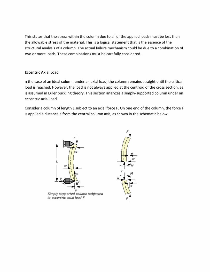
Eccentric Axial Load
n the case of an ideal column under an axial load, the column remains straight until the critical
load is reached. However, the load is not always applied at the centroid of the cross section, as
is assumed in Euler buckling theory. This section analyzes a simply-supported column under an
eccentric axial load.
Consider a column of length L subject to an axial force F. On one end of the column, the force F
is applied a distance e from the central column axis, as shown in the schematic below.

Balance the moments on the free-body diagram on the right requires that,
The governing equation for the column's transverse displacement w can then be written as,
where M was eliminated using Euler-Bernoulli beam theory. The above equation contains a
non-homogeneous term -Fe/EI and its general solution is,
where . . The coefficients A and B depend on the boundary conditions. For a simply
supported column the boundary conditions are,
The solution for the column's displacement is therefore,
where . .

Secant Formula
In practice, engineers are usually interested in the maximum stress rather than the
displacement curve alone. The secant formula discussed in this section derives the maximum
stress from the displacement formula obtained in the previous section.
The normal stress in the column results from both the direct axial load F and the bending
moment M resulting from the eccentricity e of the force application,
where A is the cross-section area, and I is the moment of inertia of the cross section.
The maximum stress is located at the extreme fiber on the concave side (y = c) of the middle
point (x = L/2) of the column,
where,
(obtained by applying basic trigonometric relations to the displacement formula in the previous
section). The parameter c is the distance from the centroidal axis to the extreme fiber on the
concave side of the column.
Expanding the formula for the maximum stress, we have,
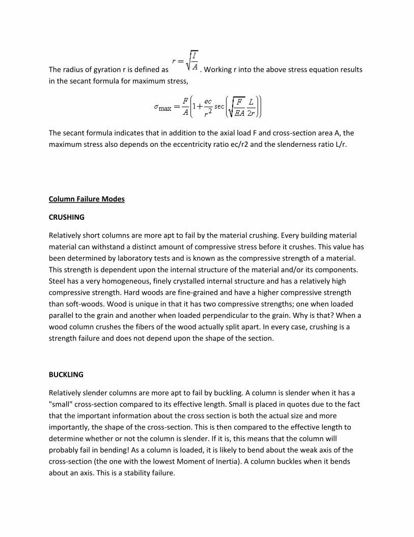
The radius of gyration r is defined as . Working r into the above stress equation results
in the secant formula for maximum stress,
The secant formula indicates that in addition to the axial load F and cross-section area A, the
maximum stress also depends on the eccentricity ratio ec/r2 and the slenderness ratio L/r.
Column Failure Modes
CRUSHING
Relatively short columns are more apt to fail by the material crushing. Every building material
material can withstand a distinct amount of compressive stress before it crushes. This value has
been determined by laboratory tests and is known as the compressive strength of a material.
This strength is dependent upon the internal structure of the material and/or its components.
Steel has a very homogeneous, finely crystalled internal structure and has a relatively high
compressive strength. Hard woods are fine-grained and have a higher compressive strength
than soft-woods. Wood is unique in that it has two compressive strengths; one when loaded
parallel to the grain and another when loaded perpendicular to the grain. Why is that? When a
wood column crushes the fibers of the wood actually split apart. In every case, crushing is a
strength failure and does not depend upon the shape of the section.
BUCKLING
Relatively slender columns are more apt to fail by buckling. A column is slender when it has a
"small" cross-section compared to its effective length. Small is placed in quotes due to the fact
that the important information about the cross section is both the actual size and more
importantly, the shape of the cross-section. This is then compared to the effective length to
determine whether or not the column is slender. If it is, this means that the column will
probably fail in bending! As a column is loaded, it is likely to bend about the weak axis of the
cross-section (the one with the lowest Moment of Inertia). A column buckles when it bends
about an axis. This is a stability failure.
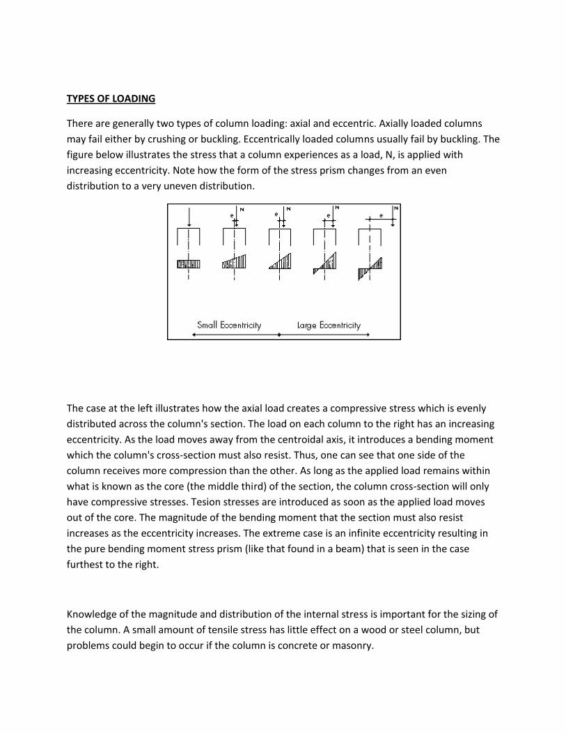
TYPES OF LOADING
There are generally two types of column loading: axial and eccentric. Axially loaded columns
may fail either by crushing or buckling. Eccentrically loaded columns usually fail by buckling. The
figure below illustrates the stress that a column experiences as a load, N, is applied with
increasing eccentricity. Note how the form of the stress prism changes from an even
distribution to a very uneven distribution.
The case at the left illustrates how the axial load creates a compressive stress which is evenly
distributed across the column's section. The load on each column to the right has an increasing
eccentricity. As the load moves away from the centroidal axis, it introduces a bending moment
which the column's cross-section must also resist. Thus, one can see that one side of the
column receives more compression than the other. As long as the applied load remains within
what is known as the core (the middle third) of the section, the column cross-section will only
have compressive stresses. Tesion stresses are introduced as soon as the applied load moves
out of the core. The magnitude of the bending moment that the section must also resist
increases as the eccentricity increases. The extreme case is an infinite eccentricity resulting in
the pure bending moment stress prism (like that found in a beam) that is seen in the case
furthest to the right.
Knowledge of the magnitude and distribution of the internal stress is important for the sizing of
the column. A small amount of tensile stress has little effect on a wood or steel column, but
problems could begin to occur if the column is concrete or masonry.


![Team Eccentric[1]](https://static.fdocuments.us/doc/165x107/577d27cd1a28ab4e1ea4dfc9/team-eccentric1.jpg)