Eccentric Communications Engineering, Inc. 35786...
19
Eccentric Communications Engineering, Inc. 35786 Geosynchronous Circle Washington, DC 20004 December 14, 2012 Det 8 AFRL/RVKVV ATTN: Luisa A. Martinez-Medina 3550 Aberdeen Ave Bldg 413, Rm. 160 Kirtland AFB, NM 87117-5776 Dear Ms. Martinez-Medina, Attached you will find our proposal in response to the AFRL/RV’s broad agency announcement W/V-Band Satellite Communications Experiment – Phase 1 (BAA-RV-12-06). ECE takes no exception to any of the design criteria put forth in the BAA, and in several areas the proposed design meets or exceeds the objective requirements. ECE’s many years of experience in high frequency satellite communications makes us the right choice to partner with your organization in this endeavor. ECE is excited to begin the technical period of performance as soon as we receive authorization to proceed. Sincerely, Colin McEwen Vice President, Research Programs, Eccentric Communications Engineering, Inc.
Transcript of Eccentric Communications Engineering, Inc. 35786...
Eccentric Communications Engineering, Inc.
35786 Geosynchronous Circle
Washington, DC 20004
December 14, 2012
Det 8 AFRL/RVKVV
ATTN: Luisa A. Martinez-Medina
3550 Aberdeen Ave
Bldg 413, Rm. 160
Kirtland AFB, NM 87117-5776
Dear Ms. Martinez-Medina,
Attached you will find our proposal in response to the AFRL/RV’s broad agency announcement
W/V-Band Satellite Communications Experiment – Phase 1 (BAA-RV-12-06). ECE takes no
exception to any of the design criteria put forth in the BAA, and in several areas the proposed
design meets or exceeds the objective requirements. ECE’s many years of experience in high
frequency satellite communications makes us the right choice to partner with your organization
in this endeavor. ECE is excited to begin the technical period of performance as soon as we
receive authorization to proceed.
Sincerely,
Colin McEwen
Vice President, Research Programs,
Eccentric Communications Engineering, Inc.
Use or disclosure of data contained on this sheet is subject to the restriction on the title page of this proposal.
1 of 18
ECCENTRIC COMMUNICATIONS ENGINEERING, INC.
W/V-Band Satellite Communications
Experiment – Phase 1 ECE6390 Fall 2012 Final Project
Colin McEwen
12/14/2012
This proposal includes data that shall not be disclosed outside the Government and shall not be
duplicated, used, or disclosed—in whole or in part—for any purpose other than to evaluate this proposal.
If, however, a contract is awarded to this offeror as a result of—or in connection with—the submission of
this data, the Government shall have the right to duplicate, use, or disclose the data to the extent provided
in the resulting contract. This restriction does not limit the Government's right to use information
contained in this data if it is obtained from another source without restriction. The data subject to this
restriction are contained in sheets 1 through 18.
Eccentric Communications Engineering, Inc.
Use or disclosure of data contained on this sheet is subject to the restriction on the title page of this proposal.
2 of 18
1. Executive Summary Eccentric Communications Engineering, Inc. (ECE) is submitting this proposal in response to the
Air Force Research Laboratory Space Vehicles Directorate (AFRL/RV) Broad Agency
Announcement BAA-RV-12-06 W/V-Band Satellite Communications Experiment (WSCE) –
Phase 1. By submitting this proposal, ECE is offering to perform the full scope of work defined
by the BAA, as outlined by the contractor’s statement of work included in Section 4, with no
exception to any of the experiment design criteria.
The WSCE program, in support of two technical objectives, requires experimental measurements
sufficient to statistically characterize atmospheric propagation physics at 71-76 GHz and 81-86
GHz to support systems engineering, assessment, and design of future operational military
satellite communication architectures and systems. ECE’s scope for Phase 1 of the experiment is
intended to fully develop the concepts required in support of both the primary and secondary
technical objectives outlined by the BAA to a level of maturity sufficient to complete the
Preliminary Design Review (PDR) milestone.
ECE’s proposal focuses on a risk-averse experiment design that maximizes the scientific benefits
of the program while minimizing the cost and technical risk to AFRL/RV. The ECE experiment
design makes use of commercial off-the-shelf (COTS) ground hardware and COTS spaceflight
qualified hardware where available, minimizing the cost and schedule associated with
developing new hardware. All threshold requirements are met by the proposed ECE experiment
design and, where practical, several of the objective requirements are satisfied. The proposed
program plan includes multiple off-ramp opportunities in the event that the program office
chooses to re-evaluate any objective requirements in favor of threshold requirements to maintain
programmatic and technical risk within an acceptable level.
2. Program Description 2.1. Overall Program Description While Ka-band satellite communication technology has been proliferating over the past decade,
the W/V-band portion of the radiofrequency (RF) spectrum remains generally unused. Before
government and industry are able to make full use of these bands, the knowledge gap must first
be filled with respect to the atmospheric propagation physics at such high frequencies. The W/V-
Band Satellite Communications Experiment is intended to address these technical unknowns.
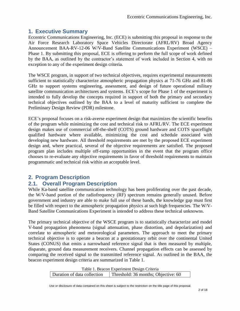
The primary technical objective of the WSCE program is to statistically characterize and model
V-band propagation phenomena (signal attenuation, phase distortion, and depolarization) and
correlate to atmospheric and meteorological parameters. The approach to meet the primary
technical objective is to operate a beacon at a geostationary orbit over the continental United
States (CONUS) that emits a narrowband reference signal that is then measured by multiple,
disparate, ground data measurement receivers. Channel propagation effects can be assessed by
comparing the received signal to the transmitted reference signal. As outlined in the BAA, the
beacon experiment design criteria are summarized in Table 1.
Table 1. Beacon Experiment Design Criteria
Duration of data collection Threshold: 36 months; Objective: 60
Eccentric Communications Engineering, Inc.
Use or disclosure of data contained on this sheet is subject to the restriction on the title page of this proposal.
3 of 18
months
Ground data collection sites Multiple – exact number to be
determined
Clear-day link margin Threshold: 30 dB; Objective: 36 dB
Signal Threshold: single tone at 73.5 GHz;
Objective: three tones (e.g., at 71 GHz,
73.5 GHz, and 76 GHz)
Supplemental K-band
beacon
Threshold: not included; Objective:
Included
Transmit power Design parameter to be determined
Transmit aperture size Design parameter to be determined
Receive aperture Design parameter to be determined
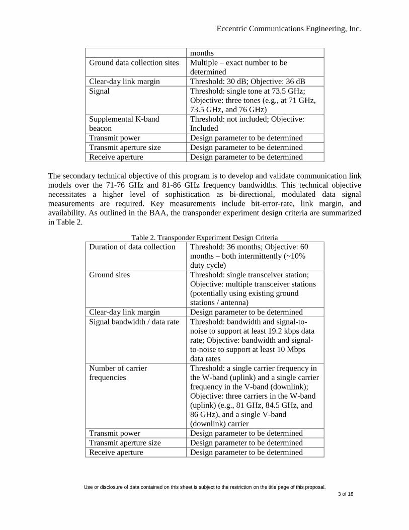
The secondary technical objective of this program is to develop and validate communication link
models over the 71-76 GHz and 81-86 GHz frequency bandwidths. This technical objective
necessitates a higher level of sophistication as bi-directional, modulated data signal
measurements are required. Key measurements include bit-error-rate, link margin, and
availability. As outlined in the BAA, the transponder experiment design criteria are summarized
in Table 2.
Table 2. Transponder Experiment Design Criteria
Duration of data collection Threshold: 36 months; Objective: 60
months – both intermittently (~10%
duty cycle)
Ground sites Threshold: single transceiver station;
Objective: multiple transceiver stations
(potentially using existing ground
stations / antenna)
Clear-day link margin Design parameter to be determined
Signal bandwidth / data rate Threshold: bandwidth and signal-to-
noise to support at least 19.2 kbps data
rate; Objective: bandwidth and signal-
to-noise to support at least 10 Mbps
data rates
Number of carrier
frequencies
Threshold: a single carrier frequency in
the W-band (uplink) and a single carrier
frequency in the V-band (downlink);
Objective: three carriers in the W-band
(uplink) (e.g., 81 GHz, 84.5 GHz, and
86 GHz), and a single V-band
(downlink) carrier
Transmit power Design parameter to be determined
Transmit aperture size Design parameter to be determined
Receive aperture Design parameter to be determined

Eccentric Communications Engineering, Inc.
Use or disclosure of data contained on this sheet is subject to the restriction on the title page of this proposal.
4 of 18
For both objectives it is assumed that the flight unit will be a hosted payload on a primary
spacecraft/bus to be determined by the Government, which will be positioned in a geostationary
orbit (GEO) over CONUS (~100 deg West longitude). As directed by the BAA, the size, weight,
and power are not considered to be limiting design requirements. It is assumed that the flight unit
command, control, health and status will be accomplished through a communications link to the
host spacecraft bus and that power will be provided by the host spacecraft.
The WSCE is planned to be accomplished in five program phases, as delineated in Table 3.
ECE’s proposed approach for Phase 1 is presented in the Section 2.2.
Table 3. WSCE Planned Program Phases
Phase 1 Concept development to the Preliminary Design Review milestone
Phase 2 System design development to the Critical Design Review milestone;
will include laboratory demonstrations for concept / design validation
Phase 3 Development and delivery of the engineering demonstration unit, the
flight-ready system, and ground data collection systems
Phase 4 Pre-launch assembly, integration, and test support of the flight hardware
Phase 5 On-orbit experiment support
2.2. Phase 1 Program Description In Phase 1 of the WSCE, ECE will further develop the experimental design concepts to a PDR
level of maturity. This phase will culminate with a PDR milestone and technical report. The
primary technical deliverables for Phase 1 are listed in Table 4. Draft and final versions of these
documents will be delivered in accordance with the contract data requirements list (CDRL).
Table 4. Phase 1 Technical Deliverables
System Design Description
Experiment Plan
Interface Definition
Environment Definition
With fee it is estimated that ECE could perform Phase 1 at a cost of roughly $2,600,000. For
more details on the cost and schedule estimates, see Section 3.2.
2.3. Approach 2.3.1. Beacon Experiment Design The primary technical objective will be accomplished by operating a beacon from GEO that
emits a narrowband reference signal that is then measured by multiple, disparate, ground data
measurement receivers. Channel propagation effects can be assessed by comparing the received
signal to the transmitted reference signal.
The proposed beacon architecture is illustrated in Figure 1, and is comprised of a K-band beacon
and a V-band beacon. Since the K-band is well characterized in literature1, it makes a good

Eccentric Communications Engineering, Inc.
Use or disclosure of data contained on this sheet is subject to the restriction on the title page of this proposal.
5 of 18
choice for an experiment reference that can be used to normalize any variations in the flight unit
output. Both beacons will have a single linear polarization.
Figure 1. Satellite Payload Architecture where Blue Area is Beacon Experiment Hardware, Yellow Area
is Transponder Experiment Hardware, and Green Area is Shared Hardware
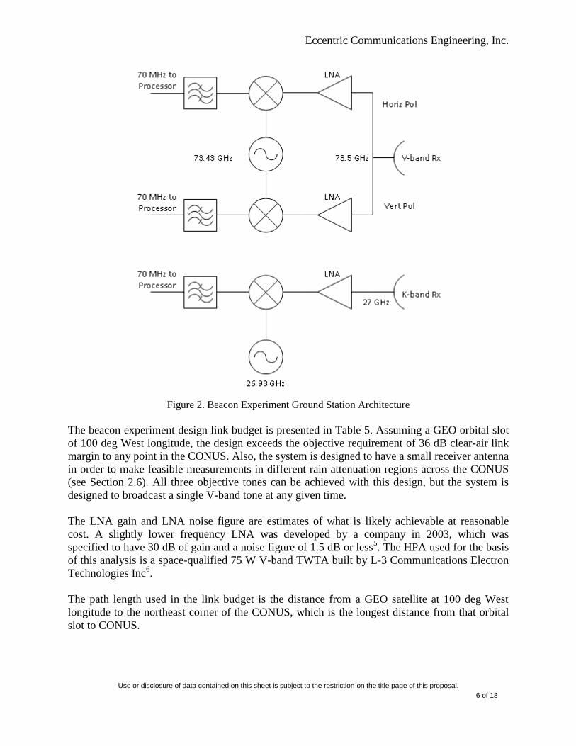
The proposed ground station configuration is illustrated in Figure 2, and is comprised of a K-
band receiver string, a V-band receiver string, and a V-band radiometer. While the V-band
beacon is broadcast on a single linear polarization, the V-band receiver string consists of two
perpendicularly oriented polarization feeds, which allows for the collection of depolarization
measurements2. Also, a radiometer is used to avoid nonlinear losses in the receiver LNA
3. Phase
distortion is measured by comparison of the received K-band and V-band signals after
compensating for known atmospheric K-band phase distortion4. And finally, signal attenuation is
measured by comparison of the radiometer measurements to the theoretical output of the V-band
beacon.
Eccentric Communications Engineering, Inc.
Use or disclosure of data contained on this sheet is subject to the restriction on the title page of this proposal.
6 of 18
Figure 2. Beacon Experiment Ground Station Architecture
The beacon experiment design link budget is presented in Table 5. Assuming a GEO orbital slot
of 100 deg West longitude, the design exceeds the objective requirement of 36 dB clear-air link
margin to any point in the CONUS. Also, the system is designed to have a small receiver antenna
in order to make feasible measurements in different rain attenuation regions across the CONUS
(see Section 2.6). All three objective tones can be achieved with this design, but the system is
designed to broadcast a single V-band tone at any given time.
The LNA gain and LNA noise figure are estimates of what is likely achievable at reasonable
cost. A slightly lower frequency LNA was developed by a company in 2003, which was
specified to have 30 dB of gain and a noise figure of 1.5 dB or less5. The HPA used for the basis
of this analysis is a space-qualified 75 W V-band TWTA built by L-3 Communications Electron
Technologies Inc6.
The path length used in the link budget is the distance from a GEO satellite at 100 deg West
longitude to the northeast corner of the CONUS, which is the longest distance from that orbital
slot to CONUS.

Eccentric Communications Engineering, Inc.
Use or disclosure of data contained on this sheet is subject to the restriction on the title page of this proposal.
7 of 18
Table 5. Beacon Experiment Design Link Budget
Miscellaneous Parameters
Speed of Light 3.00E+08 m/s 3.00E+08 m/s
Boltzman's Constant 1.38E-23 J/K 1.38E-23 J/K
Link Characteristics
V-band Beacon K-band Beacon
Downlink Frequency 73.5 GHz 27 GHz
Downlink Wavelength 4.08E-03 m 1.11E-02 m
Path Length 39720 km 39720 km
Satellite Transmit
Tx Power (75 W - V, 1 W - K) 18.8 dBW 0.0 dBW
Tx Antenna Efficiency 60 % 60 %
Tx Antenna Gain 30.4 dB 30.4 dB
Downlink
Path Loss 221.7 dB 213.0 dB
Miscellaneous Losses 3 dB 3 dB
Ground Receive
Rx Antenna Efficiency 60 % 60 %
Rx Antenna Gain 45.3 dB 36.6 dB
LNA Noise Figure 3.0 3.0
System Noise Temp 870 K 870 K
Noise Bandwidth 0.7 MHz 0.7 MHz
Thermal Noise -140.8 dB -140.8 dB
LNA Gain 24.0 dB 24.0 dB
C/N @ Receiver 34.4 dB 15.7 dB
Required Clear-Air Link Margin 36.0 dB 0.0 dB
Receiver C/N Requirement -1.6 dB 15.7 dB
2.3.2. Transponder Experiment Design The secondary technical objective will be accomplished by operating a transponder in orbit that
will receive (uplink) signals from a ground transceiver in the 81-86 GHz frequency band and
retransmit (downlink) signals to the ground transceiver in the 71-76 GHz frequency band.
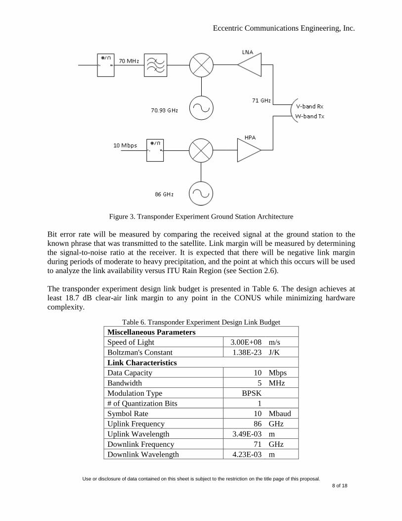
The flight unit is shown in Figure 2 and the ground unit is illustrated in Figure 3. An uncoded
binary phase shift keying (BPSK) modulated signal is broadcast from the ground station to the
flight unit, where it is received, down-converted directly from W-band to V-band, amplified, and
retransmitted to the ground. All three objective uplink frequencies can be achieved with this
design, but the system is intended to be operated on a single W-band uplink at any given time.
Eccentric Communications Engineering, Inc.
Use or disclosure of data contained on this sheet is subject to the restriction on the title page of this proposal.
8 of 18
Figure 3. Transponder Experiment Ground Station Architecture
Bit error rate will be measured by comparing the received signal at the ground station to the
known phrase that was transmitted to the satellite. Link margin will be measured by determining
the signal-to-noise ratio at the receiver. It is expected that there will be negative link margin
during periods of moderate to heavy precipitation, and the point at which this occurs will be used
to analyze the link availability versus ITU Rain Region (see Section 2.6).
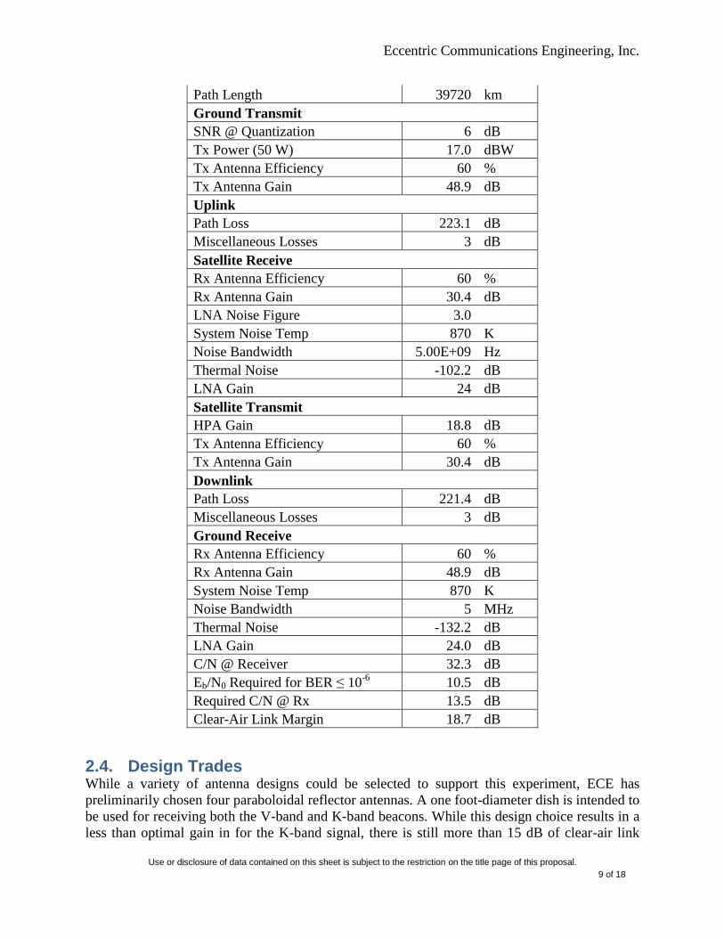
The transponder experiment design link budget is presented in Table 6. The design achieves at
least 18.7 dB clear-air link margin to any point in the CONUS while minimizing hardware
complexity.
Table 6. Transponder Experiment Design Link Budget
Miscellaneous Parameters
Speed of Light 3.00E+08 m/s
Boltzman's Constant 1.38E-23 J/K
Link Characteristics
Data Capacity 10 Mbps
Bandwidth 5 MHz
Modulation Type BPSK
# of Quantization Bits 1
Symbol Rate 10 Mbaud
Uplink Frequency 86 GHz
Uplink Wavelength 3.49E-03 m
Downlink Frequency 71 GHz
Downlink Wavelength 4.23E-03 m
Eccentric Communications Engineering, Inc.
Use or disclosure of data contained on this sheet is subject to the restriction on the title page of this proposal.
9 of 18
Path Length 39720 km
Ground Transmit
SNR @ Quantization 6 dB
Tx Power (50 W) 17.0 dBW
Tx Antenna Efficiency 60 %
Tx Antenna Gain 48.9 dB
Uplink
Path Loss 223.1 dB
Miscellaneous Losses 3 dB
Satellite Receive
Rx Antenna Efficiency 60 %
Rx Antenna Gain 30.4 dB
LNA Noise Figure 3.0
System Noise Temp 870 K
Noise Bandwidth 5.00E+09 Hz
Thermal Noise -102.2 dB
LNA Gain 24 dB
Satellite Transmit
HPA Gain 18.8 dB
Tx Antenna Efficiency 60 %
Tx Antenna Gain 30.4 dB
Downlink
Path Loss 221.4 dB
Miscellaneous Losses 3 dB
Ground Receive
Rx Antenna Efficiency 60 %
Rx Antenna Gain 48.9 dB
System Noise Temp 870 K
Noise Bandwidth 5 MHz
Thermal Noise -132.2 dB
LNA Gain 24.0 dB
C/N @ Receiver 32.3 dB
Eb/N0 Required for BER ≤ 10-6
10.5 dB
Required C/N @ Rx 13.5 dB
Clear-Air Link Margin 18.7 dB
2.4. Design Trades While a variety of antenna designs could be selected to support this experiment, ECE has
preliminarily chosen four paraboloidal reflector antennas. A one foot-diameter dish is intended to
be used for receiving both the V-band and K-band beacons. While this design choice results in a
less than optimal gain in for the K-band signal, there is still more than 15 dB of clear-air link
Eccentric Communications Engineering, Inc.
Use or disclosure of data contained on this sheet is subject to the restriction on the title page of this proposal.
10 of 18
margin. Similarly, on the satellite the W- and V-band signals for both experiments share a single
dish antenna. The W/V-band paraboloidal reflector is designed to have a 3 dB beamwidth that
spans the entire CONUS (3 deg x 6 deg). In order to ensure full CONUS coverage for the K-
band beacon, a separate K-band antenna is implemented onboard the satellite. Finally, there is a
reflector antenna at the transponder experiment ground station that is dedicated to transmitting
the modulated W-band signal and receiving the modulated V-band signal. This antenna is
designed to have a 3 dB beamwidth of 0.5 deg in order to minimize interference to/from
satellites located near the experiment’s host satellite.
The type of modulation ECE has chosen for the transponder experiment design is BPSK. QPSK
was also considered, which would have decreased the bandwidth required to achieve a 10 Mbps
link, but, since a wideband, high-power TWTA was selected in order to support the full extent of
the V-band, QPSK modulation was found to be unnecessary. By selecting BPSK, the ground
hardware architecture is simplified and the performance measurements will be easier to collect.
2.5. Risk Management As shown in Section 2.3, the ECE design is inherently risk averse. Procuring a spaceflight-
qualified LNA capable of the performance required by this experiment is the main hardware risk.
This risk is mitigated, however, by the design decision to maintain only a single W-band uplink
carrier at any time. The second highest risk is the availability of a receiver capable of measuring
the phase distortion and depolarization of the V-band beacon with a receive C/N of -1.6 dB.
However, this risk could be mitigated by procuring a larger receive antenna.
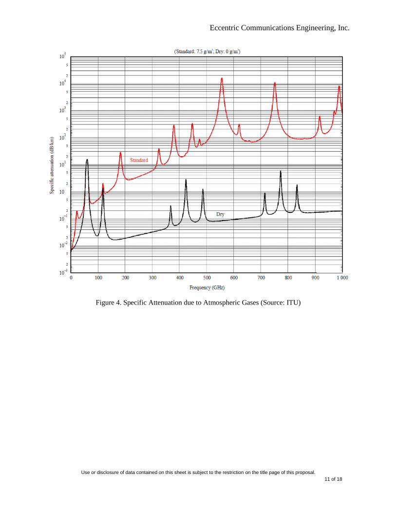
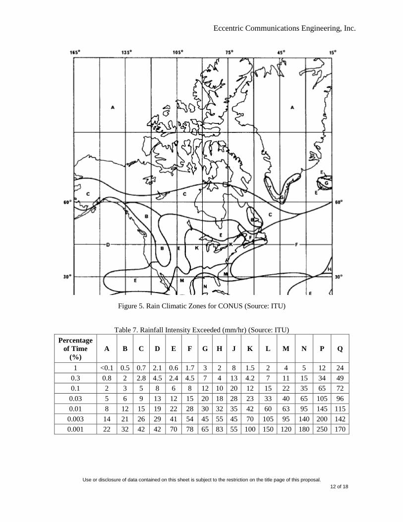
2.6. Systems Engineering It is expected that moisture in the atmosphere, including rain and rain rate, will play a major role
in the propagation physics in the W- and V-bands, as illustrated in Figure 47. By selecting, for
the beacon flight unit, a V-band antenna that is capable of providing a 3 dB beamwidth that
covers the entire CONUS, ECE will be able to collect measurements in any or all of the six rain
climatic zones that make up the CONUS (see Figure 5 and Table 7). This approach is also aided
by the flight TWTA selection, which allows for all of the experiment design requirements to be
met with a relatively simple-to-manufacture 1-ft diameter ground antenna.
Eccentric Communications Engineering, Inc.
Use or disclosure of data contained on this sheet is subject to the restriction on the title page of this proposal.
11 of 18
Figure 4. Specific Attenuation due to Atmospheric Gases (Source: ITU)
Eccentric Communications Engineering, Inc.
Use or disclosure of data contained on this sheet is subject to the restriction on the title page of this proposal.
12 of 18
Figure 5. Rain Climatic Zones for CONUS (Source: ITU)
Table 7. Rainfall Intensity Exceeded (mm/hr) (Source: ITU)
Percentage
of Time
(%) A B C D E F G H J K L M N P Q
1 <0.1 0.5 0.7 2.1 0.6 1.7 3 2 8 1.5 2 4 5 12 24
0.3 0.8 2 2.8 4.5 2.4 4.5 7 4 13 4.2 7 11 15 34 49
0.1 2 3 5 8 6 8 12 10 20 12 15 22 35 65 72
0.03 5 6 9 13 12 15 20 18 28 23 33 40 65 105 96
0.01 8 12 15 19 22 28 30 32 35 42 60 63 95 145 115
0.003 14 21 26 29 41 54 45 55 45 70 105 95 140 200 142
0.001 22 32 42 42 70 78 65 83 55 100 150 120 180 250 170
Eccentric Communications Engineering, Inc.
Use or disclosure of data contained on this sheet is subject to the restriction on the title page of this proposal.
13 of 18
3. Program Plan 3.1. Overall Program Plan Phase 1 of the program plan is explained in detail in the Section 3.2.
In Phase 2 of the program, ECE will perform full reliability and availability analyses for the
system in order to ensure a mean mission duration that supports at least the threshold
requirement of 36 months (assuming 100% duty cycle for the beacon unit and 10% duty cycle
for the transponder unit). In addition to this, laboratory simulations will be done to show that the
circuit design closes. The system requirements and verification plans will be finalized in Phase 2,
to include the host interface requirements. All hardware selections will be made and all analyses
completed in order to support a critical design review.
In Phase 3, an engineering development unit will be built and utilized for flight-like testing and
high fidelity simulation and analysis. Finally, the flight-ready system and ground data collection
systems will be provided.
In Phase 4, ECE will support pre-launch assembly, integration, and testing of the flight hardware,
including end-to-end testing between the host command interface and the ground station
hardware.
In Phase 5, ECE will provide on-orbit experiment support, to include data collection and
processing.
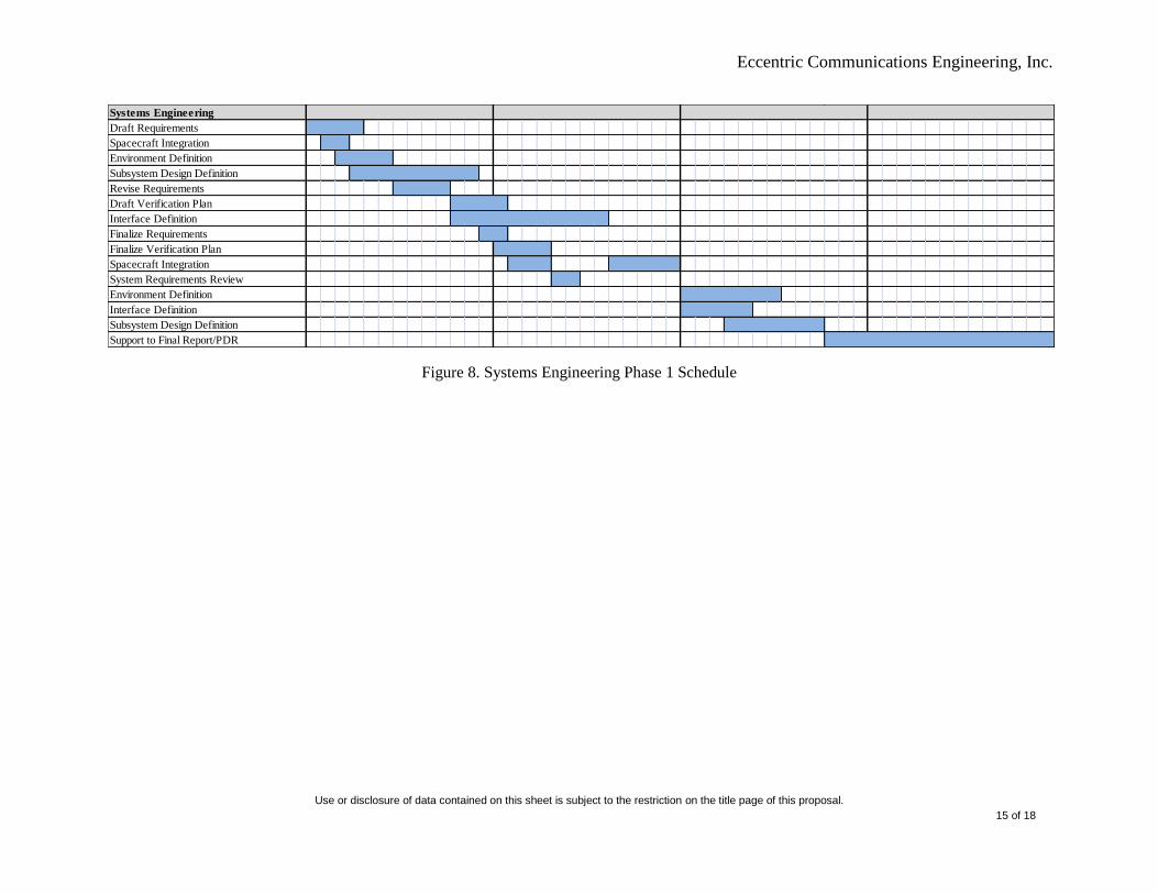
3.2. Phase 1 Program Plan The proposed period of performance (PoP) for Phase 1 is 52 weeks. The technical performance
period is the first 36 weeks. An FTE breakdown is provided in Table 8 and an IMS is shown in
Figure 6 through Figure 8. With fee it is estimated that ECE could perform Phase 1 at a cost of
roughly $2,600,000.
Table 8. FTE Breakdown for Full Period of Performance
Position
FTE over
Full PoP
Program Manager 0.5
RF Engineer III 0.5
RF Engineer II 1.35
Systems Engineer II 1.5
Technical Writer 0.4
Total 4.25

Use or disclosure of data contained on this sheet is subject to the restriction on the title page of this proposal.
14 of 18
Figure 6. Program Management Phase 1 Schedule.
Figure 7. RF Engineering Phase 1 Schedule
1 2 3 4 5 6 7 8 9 10 11 12 13 14 15 16 17 18 19 20 21 22 23 24 25 26 27 28 29 30 31 32 33 34 35 36 37 38 39 40 41 42 43 44 45 46 47 48 49 50 51 52
Program Management
Program Management
Risk Management
Prepare Monthly Report/IMS Update 1
Prepare Monthly Report/IMS Update 2
Prepare Monthly Report/IMS Update 3
Prepare Monthly Report/IMS Update 4
System Requirements Review
Prepare Monthly Report/IMS Update 5
Prepare Monthly Report/IMS Update 6
Prepare Monthly Report/IMS Update 7
Prepare Monthly Report/IMS Update 8
Prepare Monthly Report/IMS Update 9
Prepare Final Report/PDR
PDR
RF Engineering
Define Hardware Needs
Modeling & Simulation
Experiment Planning & Definition
Get Hardware Quotes
Support to Subsystem Design Definition
Finalize Prelim Link Budget
Refine Hardware Needs
Get Hardware Quotes
Refine Link Budget
Support to Interface Definition
Experiment Planning & Definition
Support to Environment Definition
Support to Spacecraft Integration
Support to Spacecraft Integration
Support to Final Report/PDR
Eccentric Communications Engineering, Inc.
Use or disclosure of data contained on this sheet is subject to the restriction on the title page of this proposal.
15 of 18
Figure 8. Systems Engineering Phase 1 Schedule
Systems Engineering
Draft Requirements
Spacecraft Integration
Environment Definition
Subsystem Design Definition
Revise Requirements
Draft Verification Plan
Interface Definition
Finalize Requirements
Finalize Verification Plan
Spacecraft Integration
System Requirements Review
Environment Definition
Interface Definition
Subsystem Design Definition
Support to Final Report/PDR

Use or disclosure of data contained on this sheet is subject to the restriction on the title page of this proposal.
16 of 18
4. Contractor’s Statement of Work (C-SOW) The preliminary C-SOW is listed in Table 9.
Table 9. Contractor’s Statement of Work
1.1 The contractor shall provide copies of presentation materials (slides) to the Government
for all program meeting and program reviews to include the kick-off meeting, quarterly
review meetings, technical interchange meetings, and design reviews, in accordance with
CDRL A001.
1.2 The contractor shall deliver monthly status and execution reports in accordance with
CDRL A002.
1.3 The contractor shall deliver the Scientific and Technical Report in accordance with CDRL
A003.
1.4 The contractor shall deliver an updated IMS in accordance with CDRL A004.
1.5 The contractor shall deliver an updated Risk Assessment and Management Plan in
accordance with CDRL A005.
1.6 The contractor shall deliver a draft System Design Description document in accordance
with CDRL A006.
1.7 The contractor shall deliver a draft Experiment Plan document in accordance with CDRL
A007.
1.8 The contractor shall deliver a draft Interface Definition document in accordance with
CDRL A008.
1.9 The contractor shall deliver a draft Environment Definition document in accordance with
CDRL A009.
2.1 The contractor shall hold a system requirements review with entry and exit criteria to be
defined after ATP.
2.2 The contractor shall perform modeling and simulation to demonstrate that the proposed
concept is feasible and will meet mission requirements (propagation channel, link, RF
systems, size, weight, power requirements)
2.3 The contractor shall deliver sub-system design descriptions (space segment, ground
segment, hardware, software)
2.4 The contractor shall analyze the experiment design's interface to a potential host satellite,
to include thermal, power, command and telemetry, and EMI/EMC considerations.
2.5 The contractor shall hold a preliminary design review with entry and exit criteria to be
defined after ATP.
Eccentric Communications Engineering, Inc.
Use or disclosure of data contained on this sheet is subject to the restriction on the title page of this proposal.
17 of 18
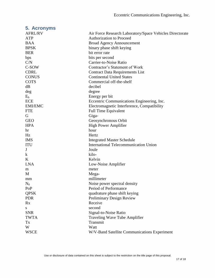
5. Acronyms AFRL/RV Air Force Research Laboratory/Space Vehicles Directorate
ATP Authorization to Proceed
BAA Broad Agency Announcement
BPSK binary phase shift keying
BER bit error rate
bps bits per second
C/N Carrier-to-Noise Ratio
C-SOW Contractor’s Statement of Work
CDRL Contract Data Requirements List
CONUS Continental United States
COTS Commercial off-the-shelf
dB decibel
deg degree
Eb Energy per bit
ECE Eccentric Communications Engineering, Inc.
EMI/EMC Electromagnetic Interference, Compatibility
FTE Full Time Equivalent
G Giga-
GEO Geosynchronous Orbit
HPA High Power Amplifier
hr hour
Hz Hertz
IMS Integrated Master Schedule
ITU International Telecommunication Union
J Joule
k kilo-
K Kelvin
LNA Low-Noise Amplifier
m meter
M Mega-
mm millimeter
N0 Noise power spectral density
PoP Period of Performance
QPSK quadrature phase shift keying
PDR Preliminary Design Review
Rx Receive
s second
SNR Signal-to-Noise Ratio
TWTA Traveling Wave Tube Amplifier
Tx Transmit
W Watt
WSCE W/V-Band Satellite Communications Experiment
Eccentric Communications Engineering, Inc.
Use or disclosure of data contained on this sheet is subject to the restriction on the title page of this proposal.
18 of 18
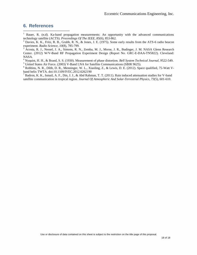
6. References 1 Bauer, R. (n.d). Ka-band propagation measurements: An opportunity with the advanced communications
technology satellite (ACTS). Proceedings Of The IEEE, 85(6), 853-862. 2 Davies, K. K., Fritz, R. B., Grubb, R. N., & Jones, J. E. (1975). Some early results from the ATS-6 radio beacon
experiment. Radio Science, 10(8), 785-799. 3 Acosta, R. J., Nessel, J. A., Simons, R. N., Zemba, M. J., Morse, J. R., Budinger, J. M. NASA Glenn Research
Center. (2012) W/V-Band RF Propagation Experiment Design (Report No. GRC-E-DAA-TN5822). Cleveland:
NASA. 4 Nyquist, H. H., & Brand, S. S. (1930). Measurement of phase distortion. Bell System Technical Journal, 9522-549.
5 United States Air Force. (2003) V-Band LNA for Satellite Communications (SBIR 9625).
6 Robbins, N. R., Dibb, D. R., Menninger, W. L., Xiaoling, Z., & Lewis, D. E. (2012). Space qualified, 75-Watt V-
band helix TWTA. doi:10.1109/IVEC.2012.6262190 7 Badron, K. K., Ismail, A. F., Din, J. J., & Abd Rahman, T. T. (2011). Rain induced attenuation studies for V-band
satellite communication in tropical region. Journal Of Atmospheric And Solar-Terrestrial Physics, 73(5), 601-610.