EB 3000 - Greisinger
19
E35.0.01.6C-03 Manual for connection and operation of the EB 3000 page 1 of 19 Manual for connection and operation of EASYBus-control, display and supervisory device EB 3000 as of Version 1.7 GREISINGER electronic GmbH D - 93128 Regenstauf, Hans-Sachs-Strae 26 Tel.: 09402 / 9383-0, Fax: 09402 / 9383-33, e-mail: [email protected]
Transcript of EB 3000 - Greisinger

E35.0.01.6C-03 Manual for connection and operation of the EB 3000 page 1 of 19
Manual for connection and operation of
EASYBus-control, display and supervisory device
EB 3000as of Version 1.7
GREISINGER electronic GmbHD - 93128 Regenstauf, Hans-Sachs-Straße 26Tel.: 09402 / 9383-0, Fax: 09402 / 9383-33, e-mail: [email protected]

E35.0.01.6C-03 Manual for connection and operation of the EB 3000 page 2 of 19
I N D E X1. SAFETY REGULATIONS .......................................................................................................................................... 3
2. INTRODUCTION ........................................................................................................................................................ 4
2.1. EASYBUS-terms and definitions ......................................................................................................................... 4
3. DISPLAY ELEMENTS AND PUSHBUTTONS........................................................................................................ 5
4. ELECTRIC CONNECTION ....................................................................................................................................... 6
4.1. Terminal assignment................................................................................................................................................ 64.2. Connection data ....................................................................................................................................................... 64.3. Connection example ................................................................................................................................................ 7
4.3.1. Connection information: ................................................................................................................................... 7
5. COMMISSIONING AND CONFIGURATION OF THE EB3000 .......................................................................... 8
5.1. Initial commissioning of the EB3000 ...................................................................................................................... 8
6. OPERATION OF THE EB3000.................................................................................................................................. 8
6.1. How to display the current measurement values...................................................................................................... 86.2. How to display or reset the min-/max-values .......................................................................................................... 96.3. Setting of switching points....................................................................................................................................... 96.4. Setting of alarm limits.............................................................................................................................................. 9
7. ERROR CODES ......................................................................................................................................................... 11
8. SPECIFICATION....................................................................................................................................................... 14
9. DISPOSAL NOTES.................................................................................................................................................... 14
10. EB3000 - CONFIGURATION................................................................................................................................. 15
10.1. EASYBUS - Configurator ................................................................................................................................... 1510.1.1. Interface configuration.................................................................................................................................. 1510.1.2. Perform EASYBUS system initialisation ..................................................................................................... 1510.1.3. Read EASYBUS........................................................................................................................................... 15
10.2. EB3000 - Configuration....................................................................................................................................... 1610.2.1. Tab: monitoring / display............................................................................................................................. 1610.2.2. Tab: control outputs ..................................................................................................................................... 1810.2.3. Tab: alarm.................................................................................................................................................... 1810.2.4. Tab: virtual channels.................................................................................................................................... 1910.2.5. Tab: others ................................................................................................................................................... 19

E35.0.01.6C-03 Manual for connection and operation of the EB 3000 page 3 of 19
1. Safety regulationsThis device was designed and tested considering the Safety regulations for electronic measuring devices.Faultless operation and reliability in operation of the measuring device can only be assured if the GeneralSafety Measures and the devices specific safety regulation mentioned in this users manual are considered.1. Faultless operation and reliability in operation of the measuring device can only be assured if the device
is used within the climatic conditions specified in the chapter �Specifications�.2. Always disconnect the device from its supply before opening it. Take care that nobody can touch any of
the unit�s contacts after installing the device.3. Standard regulations for operation and safety for electrical, light and heavy current equipment have to be
observed, with particular attention paid to the national safety regulations (e.g. VDE 0100).4. When connecting the device to other devices (e.g. the PC) the interconnection has to be designed most
thoroughly, as internal connections in third-party devices (e.g. connection of ground with protective earth)may lead to undesired voltage potentials.
5. The device must be switched off and must be marked against using again, in case of obvious malfunc-tions of the device which are e.g.:- visible damage- no prescripted working of the device- storing the device under inappropriate conditions for longer timeWhen not sure, the device should be sent to the manufacturer for repairing or servicing.
Attention: When running electric devices, parts of them will always be electrically live.Unless the warnings are observed serious personal injuries or damage to propertymay result. Skilled personnel only should be allowed to work with this device. For trou-ble-free and safe operation of the device please ensure professional transport, stor-age, installation and connection as well as proper operation and maintenance.
Skilled personnelare persons familiar with installation, connection, commissioning and operation of the product and have pro-fessional qualification relating to their job.
For example:
� Training or instruction resp. qualifications to switch on or off, isolate, ground and mark electric circuits anddevices or systems.
� Training or instruction according to the state.
� First-aid training.
-
-
ATTENTION:Do NOT use this product as safety or emergency stopping device, or in any other application where failure of the product could result in personal injury or material damage.
Failure to comply with these instructions could result in death or serious injury and material damage.

E35.0.01.6C-03 Manual for connection and operation of the EB 3000 page 4 of 19
2. IntroductionThe EB3000 is an universal control, display and supervisory device for EASYBUS-sensor modules.The EB3000 is equipped with 20 internal channels (channel-nr. 1..20), which can be allocated arbitrary todifferent EASYBUS-measurement channels and 2 virtual channels (channel-nr. 21 and 22), to download arbi-trary calculation functions.
Furthermore the EB3000 has 4 switching outputs and an alarm output.
The 22 channels can be allocated arbitrary to the 4 switching outputs to realise different type of control (2-point-, 3-point-controller, stepping switch etc.).
Due to load arbitrary calculation functions it is possible to realise extensive display and control functions (as
averaging, Difference regulation etc. .The device features 2 displays: a 4-digit 13mm high 7-segment display (main display) to indicate measure-ment values or error codes and a 2-digit 7mm high 7-segment display (auxiliary display) for indication of thefree configurable channel description.Additionally there are 4 LED´s for displaying the unit of the current measurement channel, 4 LED�s for dis-playing the actual state of the switching outputs and 3 LED�s which illuminates in case of alarm or in case of aselected min-/max-value.
The device has 2 EASYBUS-Interfaces:- EASYBUS-output: connection for the EASYBUS-sensor modules- EASYBUS-input: permits via level converter (e.g. EBW1, EBW64, ...) communication with a superior
computer (master).
The EB3000 cyclically enquires all the allocated measurement channels. The sequence for processing thechannels isn�t firm, because there is a dynamic request fitted to each channels slightest updating-rate (time-out). Measurement channels with fast turn of events are frequently requested as measurement channels withslow turn of events.
The EB3000 checks the compliance of the required updating-rate. If the enquiry of a measurement channel,within a specified time-interval, as a result of bus capacity overload (e.g. by frequent and time-consumingenquiries of the master), is not possible, a �timeout�-errormessage indicates on the display and alarm is acti-vated. If not required, timeout-control can also be deactivated.
Before the EB3000 can be used, it has to be configured for the customer�s application(see chapter 5).
2.1. EASYBUS-terms and definitionsDeclaration of used terms and definitions:EASYBUS-sensor modules sensor module for connection on EASYBUS
(e.g. EASYLOG 40K, EASYLOG 24RFT, EASYLOG 40NS, EBHT)EASYBUS-measurement channel measurement channel of an EASYBUS-sensor module
The EASYBUS-modules can feature one ore more measurement channels(e.g. EASYLOG 24RFT and EBHT features 2 channels � one channel for humid-ity and one channel for temperature measurement)
Out1
EB3000 GREISINGERelectronic
Out2 Out3 Out4°C
%RH
max
minAlarm
SET1 2 3 4

E35.0.01.6C-03 Manual for connection and operation of the EB 3000 page 5 of 19
3. Display elements and pushbuttons
1 Key 1:
2 Key 2:Key 3:
3 Key 4:
4 Main displa
5 Auxiliary di
6 Min-/max-v
7 Alarm displ
8 LED�s Out1
9 LED�s 1...4:
4
5
6
7
8
changswitch
changchangincreasetting
interruackno
y: indica
splay: indica
alues: illumin
ay: illumin
...4: indica
displa
Out1
EB3000 GREISINGERelectronic
Out2 Out3 Out4°C
%RH
max
minAlarm
SET1 2 3 4
9
1 2 3
Device front view
e-over to setting mode (in combination with key 2 or 3)ing between indication of current value, min-value and max-value
e-over to next measurement channele-over to further measurement channelsing / decreasing of the last setting mode selection
ption / recognition of the last settingwledgement of an error message
tion of current measurement value resp. min.-/max-value
tion of current measurement channel
ates in case of a selected min-/max-value
ates in case of an alarm
tes the actual state of the switching outputs
ys the unit of the current measurement channel

E35.0.01.6C-03 Manual for connection and operation of the EB 3000 page 6 of 19
4. Electric connectionElectric connection and commissioning of the device must be carried out by trained and skilled personnel.Wrong connection may lead to the destruction of the device, in which case we cannot assume anywarranty.
Make it a rule to always mount screw-type/plug-in terminals while they are still loose and connect only later. If terminalsare mounted after connection there is a risk that soldering eyes may come loose. Please use suitable screw-driver anddo not tighten screws by force.
4.1. Terminal assignment
14 Switching output 1..4 (common connector)13 Switching output 1 (normally open)12 Switching output 2 (normally open)11 Switching output 3 (normally open)10 Switching output 4 (normally open)9 Alarm output (normally closed)8 Alarm output (normally open)7 Alarm output (common connector)6 Supply voltage: 230VAC
5 Supply voltage: 230VAC
4 EASYBUS-Input (to PC/Host)
3 EASYBUS-Input (to PC/Host)
2 EASYBUS-Output (to EASYBUS-sensor modules)
1 EASYBUS-Output (to EASYBUS-sensor modules)
4.2. Connection data
typical limitationsbetweenterminal min. max. min. max.
notes
Supply voltage 5 and 6 207 VAC 243 VAC 250 VAC or as specified on rating plate
Switching outputs
14 and 13,14 and 12,14 and 11,14 and 10
250 VAC5A
(ohmic load)
Use RC circuit elements orvaristors for inductive loads
Alarm output 7 and 8, 9250 VAC
5A(ohmic load)
Use RC circuit elements orvaristors for inductive loads
EASYBUS-output 1 and 2 36 VDC
EASYBUS-input 3 and 4 36 VDC
These limits must not be exceeded (not even for a short time) !
Rel 1Rel 2
230 V AC
Rel 3Rel 4
AlarmEB
inEB
out

E35.0.01.6C-03 Manual for connection and operation of the EB 3000 page 7 of 19
4.3. Connection example
Hint: Isp
4.3.1. ConnThe interfacThe module
PleaPlea
Bus loads ofEASYLOG-faEBN:EBHT, EBT,GIA20EB, G
W hen connthe maximal
Worked sam1) Connecti
5 * 2 +2) Connecti
15 * 2
3) Connecti4 * 1.5
Please note
n order to avoid undefined input states and unwanted or wrong switching processes, weuggest to connect the device�s switching outputs after You have configured the deviceroperly.
ection information:e-converter can supply the specifieded numbers of EASYBUS standard loads (max. 30 pieces). management is limited to max. 20 EASYBUS-measuring channels.
se note that some EASYBUS -modules have a higher bus load as the standard load!se notice the corresponding specification in the module manual.
some EASYBUS modules:mily: 2 EASYBUS standard loads
2 EASYBUS standard loads EBH: 1.5 EASYBUS standard loadsIR2002: 1 EASYBUS standard load
ecting the modules keep in mind that the sum of all bus loads of the modules must not exceed allowed number.
ple:on of 5 EASYLOG, 8 EBHT and 7 GIA20EB: 8 * 1.5 + 7 * 1 = 10 + 12 + 7 = 29 standard loads (20 devices) => connection is possible
on of 15 EASYLOG and 2 EBN: + 2 * 2 = 30 + 4 = 34 standard loads (17 devices) => EB3000 are overloaded!
on of 4 EBHT and 20 GIA20EB:+ 20 * 1 = 6 + 20 = 26 standard loads (24 devices / 28 meas. channels) => max. number of meas. channels transcended!
: The EASYBUS-modules can feature more as one measurement channels (e.g: EBHT, ...)
EB 3000Top side
switching outputs
alarm output
mains: 230V
level converterEBW1,EBW 64..
sensor module
sensor module
Example for connection
2 wire cable PC

E35.0.01.6C-03 Manual for connection and operation of the EB 3000 page 8 of 19
5. Commissioning and configuration of the EB3000For configuration and commissioning of the EB3000 the software EASYBus-configurator is necessary. Youwill find this software for free on one of our different product-CD�s or on homepage www.greisinger.de underarea SERVICE beneath FREEWARE.
5.1. Initial commissioning of the EB3000Before commissioning the EB3000, a proper and complete installation and wiring of the entire EASYBus-system is required.
Please start software EASYBus-Configurator and carry out a system initialisation. For further details readthe operating manual of the EASYBus-Configurator.
By double-click on EB3000-symbol the EB3000-configuration window appears.
Choose register-tab monitoring / display and make following settings for each channel:
- allocation of a measurement channel- setting of the required timeout- setting of display endurance, text for auxiliary display and appearance of the unit-LED�s
Choose register-tab control outputs and make following settings for each output:
- allocation of a channel number- setting of switching-on-point, switching-off-point, switching-delay and function
To use EB3000 calculation functions, choose register-tab virtual channels for programming the desired func-tion for virtual channel 1 or 2.
For details see chapter 9. EB3000-Configuration
6. Operation of the EB3000Hint: Keys 2 and 3 are equipped with a 'roll-function' for an easy input of values. By pushing this key shortly the
display increases (key 2) resp. decreases (key 3) at any one time about 1 digit.By pushing the keys longer than 1 second the value starts to count up resp. to count down, whereas thecounting speed increases after a short time.
6.1. How to display the current measurement valuesIn the standard mode the current measurement values (actual values) of the measurement channels will bedisplayed in the main display.In the auxiliary display the text appears, which was configured for the respective channel.
There are two modes of display:
Static display:The selected channel will be displayed constantly; use keys 2 (up) and 3 (down) for channel selection.
Cyclic display:All channels will be indicated one after another by the adjusted display endurance. By configuration displayendurance can be set for each channel separately (see chapter 5). If cyclic display is activated, the decimalpoint right next to the auxiliary display illuminates.
Key-operating:- key 2 and 3 shortly pushed: cyclic display switches on/off- key 2 shortly pushed: displaying of next channel- key 3 shortly pushed: displaying of previous channel

E35.0.01.6C-03 Manual for connection and operation of the EB 3000 page 9 of 19
6.2. How to display or reset the min-/max-valuesYou can call and display the min-/max-values of the EASYBUS-measurement channels by using EB3000.Hint: The EB3000 can only readout the respective min-/max-values. The values stored in the
respective sensor modules will not be saved in the EB3000.
If a min-/max-value is shown, LED �min� resp. �max� illuminates.
Key-operating:- Key 1 shortly pushed: display changes between actual value, min-value and max-value- Key 1 pushed >1 sec.: if cyclic display = off: clear min-/max-values of the displayed measurement
channel.if cyclic display = on: clear min-/max-values of all activated measurement
channels.
After 30 sec. the display of the min-/max-values automatically finish and the actual value is shown again.
6.3. Setting of switching pointsThe switching-on-points and switching-off-points of the outputs can be called and changed via the inputkeys. Therefore only switching outputs with an allocated channel are shown. If no channel was allocated tothe switching output a call of function �setting of switching points� is not possible.
Please note: If no key is pushed by inputing a value longer than 10 sec., it will be changed to the parametricdisplay again, after another 30 sec. the switching point setting of the device will be stopped. Not stored modifi-cations will not be saved and are lost!
Hint: A call is only possible, if the display of the device shows the actual value- Push key 1 and 2 for >1 second
In the main display �X.on� resp. �X.off � appears. (X = number of the switching output, on = switching-on-point, off = switching-off-point).In the auxiliary display the text of the allocated channel appears.
- Use key 1 to select the adjustable switching parameter.
- Push key 2 or 3.In the main display the currently adjusted switching point appears.
- Use key 2 and 3 to set the new desired value, whereas this output shall be switched on or off.
- Use key 1 to acknowledge the adjusted switching point. The new switching point will be saved and inthe main display �X.on� resp. �X.off � appears again.
With key 4 you can cancel the setting at any time, the made modification is resetted and in the maindisplay �X.on� resp. �X.off � appears again.
- Use key 1 to select the next adjustable switching parameter and set as described.
With key 4 you can cancel/finish the setting of the switching point at any time, and the actual measure-ment value is displayed again.
Hint: The setting of the switching points can also be performed comfortable for each channel with software�EASYBUS-Configurator� (see chapter 8 � appendix).
6.4. Setting of alarm limitsIf the connected EASYBUS-measurement channel supports an alarm function the min-/max alarm limits andthe alarm delay can be called and changed via the input keys.Please note: If no key is pushed by inputing a value longer than 10 sec., it will be changed to the parametricdisplay again, after another 30 sec. the switching point setting of the device will be stopped. Not stored modifi-cations will not be saved and are lost!
Hint: Here you can call and change the alarm limits of the EASYBUS-measurement channel.The alarm limits stored in the EASYBUS-sensor modules will not be saved in the EB3000.
The settings of the alarm limits will only be carried out for the currently displayed measurement channel.
TIPP: For setting the alarm limits we suggested to switch-off the cyclic display for a �manually� se-lection of the setting channel.
E35.0.01.6C-03 Manual for connection and operation of the EB 3000 page 10 of 19
Hint: A call is only possible, if the display of the device shows the actual value
- Push key 1 and 3 for >1 second.In the display �AL.Hi� appears (alarm high, max-alarm limit).
- Push key 2 or 3.In the main display the currently adjusted max-alarm limit appears.
- Use key 2 and 3 for setting the desired new value, when max-alarm shall be released.
With key 4 you can cancel the setting at any time, the made modification is resetted and in the maindisplay �AL.Hi� appears again.
- Confirm the adjusted value with key 1, in the main display �AL.Hi� appears again.
- Press key 1 again, and the adjusted alarm value will be saved into the sensor module, in the display�AL.Lo� appears (alarm low, min-alarm limit).
If an error occurs when saving the value into the sensor module, this error will be indicated on the maindisplay. The error must be acknowledged by pushing key 1. The display shows furthermore parameter�AL.Hi�.
With key 4 you can cancel the settings at any time, the made modifications are resetted and the actualmeasurement value is displayed.
- Push key 2 or 3.In the main display the currently adjusted min-alarm limit appears.
- Use key 2 and 3 for setting the desired new value, when min-alarm shall be released.
- Confirm the adjusted value with key 1, in the main display �AL.Lo� appears again.
With key 4 you can cancel the setting at any time, the made modification is resetted and in the maindisplay �AL.Lo� appears again.
- Press key 1 again, and the adjusted alarm value will be saved into the sensor module, in the display�A.dEL� appears (alarm delay).
If an error occurs when saving the value into the sensor module, this error will be indicated on the maindisplay. The error must be acknowledged by pushing key 1. The display shows furthermore parameter�AL.Lo�.
With key 4 you can cancel the settings at any time, the made modifications are resetted and the actualmeasurement value is displayed.
- Push key 2 or 3.In the main display the currently adjusted alarm delay in minutes appears.
- Use key 2 and 3 for setting the desired new alarm delay.
- Confirm the adjusted value with key 1, in the main display �A.dEL� appears again.
With key 4 you can cancel the setting at any time, the made modification is resetted and in the maindisplay �A.dEL� appears again.
- Press key 1 again, and the adjusted alarm delay will be saved into the sensor module, in the display�AL.Hi� appears again (alarm high, max-alarm limit).
If an error occurs when saving the value into the sensor module, this error will be indicated on the maindisplay. The error must be acknowledged by pushing key 1. The display shows furthermore parameter�A.dEL�.
With key 4 you can cancel the settings at any time, the made modifications are resetted and the actualmeasurement value is displayed.
- Press key 4 to complete the settings.

E35.0.01.6C-03 Manual for connection and operation of the EB 3000 page 11 of 19
7. Error codesWhen detecting an operating state which is not permissible, or the current EASYBUS-measurement channelhas an undefined operating state, the EB3000 will display an appropriate error code.
The following error codes are defined. An errror code will displayed, if an EASYBUS-measurement channelwith an occurred error is selected.
Err.1: Exceeding of the measurement rangeIndicates that the valid measuring range of the EASYBUS-measurement channel has been exceeded.
For possible causes and remedies please read the operation manual of the EASYBUS-sensor mod-ule
Err.2: Values below the measuring rangeIndicates that the values are below the valid measuring range of the EASYBUS-measurement channel.
For possible causes and remedies please read the operation manual of the EASYBUS-sensor mod-ule
Err.3: Display range has been exceededIndicates that the valid display range (9999 digit) of the device has been exceeded.
Possible causes: - Incorrect scale.- Counter overflow.
Remedies: - The error-message will be reset if the display value is below 9999.- Reset the counter.
When happening frequently, check the scale-setting, maybe it was set too high and should be reduced(e.g. factor 10)
Err.4: Values below display rangeIndicates that display value is below the valid display range of the device (-1999 digit).
Possible causes: - Incorrect scale.- Counter underflow.
Remedies: - The error-message will be reset if the display value is above -1999.- Reset the counter
When happening frequently, check the scale-setting, maybe it was set too low and should be increased(e.g. factor 10)
Err.7: System-errorThe device features an integrated self-diagnostic-function which checks essential parts of the de-vice permanently. When detecting a failure, error-message Err.7 will be displayed.
For possible causes and remedies please read the operation manual of the EASYBUS-sensor mod-ule
Err.9: Sensor defectiveThe device features an integrated diagnostic-function for the connected sensor resp. transmitter.When detecting a failure, error-message Err.9 will be displayed.
For possible causes and remedies please read the operation manual of the EASYBUS-sensor
module

E35.0.01.6C-03 Manual for connection and operation of the EB 3000 page 12 of 19
Er.11: Value could not be calculatedIndicates a measuring value, needed for calculation of the display value, is faulty resp. out ofrange.
For possible causes and remedies please read the operation manual of the EASYBUS-sensor mod-ule
Er.12: Received datasets invalidIndicates, that the received EASYBUS-sensor module datasets for this EASYBUS-measurementchannel is invalid.
Possible causes: - EASYBUS-measurement channel with an error indication
Remedies: - check EASYBUS-sensor module
E.-23: Transmission error: EASYBus-modul not respondingIndicates, that the attached EASYBUS-sensor module does not responding an enquiry.
Possible causes: - EASYBUS-sensor module not connected or defective- incorrect system initialisation or configuration- uncouple / access of the sensor module via PC-software (e.g. searching of GSOFT40K)
Remedies: - check EASYBUS-sensor module and connection- perform new configuration of the EB3000- check bus access via PC-software
E.-25: Transmission error: CRC-Code wrongIndicates, that the enquiry of an attached EASYBUS-measurement channel has generated an CRC-error.
Possible causes: - multiple attached EASYBUS-measurement channels have the same address- EASYBUS-sensor module defective
Remedies: - perform new EASYBUS-system initialisation
E.-38: No acknowledge received (unknown operation call)Indicates, that the selected function of the attached EASYBUS-measurement channel (at present) is notsupported.
Possible causes: - a working Logger accepts some settings only in stop-modus- module = GIA20EB: alarm function not activated
Remedies: - stop Logger- activate alarm function of the GIA20EB beneath �out�
E.-41: Data received within locked rangeIndicates, that received data are not in a valid EASYBUS-value range.
Possible causes: - EASYBUS-sensor module incorrect configured or defective
Remedies: - check EASYBUS-sensor module
E.-44: Transmitted data modified removedIndicates, that transmitted data varied from data, saved and acknowledged from EASYBUS-sensormodule.
Possible causes: - The transmitted data are outside of a permissible value range of the EASYBUS-measurement channel.- The EASYBUS-sensor module has accepted a possible min / max value and has send back this value to the EB3000.
Remedies: ---

E35.0.01.6C-03 Manual for connection and operation of the EB 3000 page 13 of 19
----: no measurement channel allocatedIndicates, that the displayed channel is configured with no allocated EASYBUS-measurement chan-nel.
Possible causes: - incorrect configuration
Remedies: - perform new configuration of the EB3000
t.out: Timeout occurrenceThis error message alternates with the current display value and indicates, that�s not possible toenquire the EASYBUS-measurement channel within the minimum required updating-rate.
Possible causes: - a system initialisation was performed- incorrect configuration- bus is blocked in fact of a master requiry
Remedies: - remove alarm by pushing key 4 or by using EASYBUS-Configurator software- perform new configuration of the EB3000
The following system-error-codes are defined:
. : no measurement channel for indication selected(only a point is indicated down right of the display)
Indicates, that all channels are configured with display endurance 0.
Er.49: Capacity overload of the EASYBUS-outputThis error message alternates with the current display value and indicates, that the max. allowablevalue of the EASYBUS-output has been exceeded.
Possible causes: - too many EASYBUS-sensor modules connected on EB3000- connection line with shortcut
Remedies: - check connection of the EASYBUS-sensor modules

E35.0.01.6C-03 Manual for connection and operation of the EB 3000 page 14 of 19
8. SpecificationDisplay range: -1999 ... +9999 DigitResolution: Automatically recognition of the resolution of the connected EASYBUS-
measurement channel. Decimal point is set automatically.Accuracy: Depending on the respective EASYBUS-measurement channel.
The EB3000 is receiving this value digital without additional error.
Sensors: All EASYBUS-sensor modules (inclusive EASYLOG , GIA20EB, GIR2002, ...) areconnectable. The connection effected not polarised via 2-wire connection cable in ring-,tree-, or star- configuration.
- sensor supply: Effected through EB3000- max. bus load: max. 30 EASYBUS standard loads- max. meas. channels: 20- permissible cabel length: 200 m (depending on cabeltyp and wiring)
Switching outputs: 4 relay outputs (normally open), switching to one common connector.Each output can arbitrary allocate to each measurement channel.
- Switching capacity: 230VAC, 5A, ohmic load- Output functions: 2-point controller, 2-point controller inverse,
switching point, switching delay for each output individually adjustable.
Alarm output: 1 relay output (changeover)- Switching capacity: 230VAC, 5A, ohmic load- Alarm functions: Collective alarm for all sensors,
alarm settings for all sensors changeable
Displays: Main display: 4-digit red 13mm high 7-segment LED-displayAuxiliary display: 2-digit red 7mm high 7-segment LED-display11 additional LED�s for unit-, switching function- and alarm display
Operating: via 4 pushbuttonsHost-Interface: EASYBUS-Interface, electrically isolated
Nominal temperature: 25°COperating temperature: -25 ... +50°CRelative humidity: 0 ... 80% r.H. (non-condensing)Storage temperature: 30 ... +70°C
Power supply: 230V AC 50/60Hz, or as specified on rating plateNominal operating power: ca. 9 VA
Housing: Standard rack housing 48 x 96 x 100mm (H x B x T)Panel cut-out: 43 x 90,5 mm (H x B)Electric connection: Screw-type/plug-in terminal; cross-section 0.14 ... 1.5 mm²Protection class: Front IP54, with optional sealing insert IP65EMC: EN61326 +A1 +A2 (appendix A, class B),
additional errors: < 1% FSWhen connecting long leads adequate measures against voltage surges have tobe taken.
9. Disposal notesThis device must not be disposed as �residual waste�.To dispose this device, please send it directly to us (adequately stamped). We will dispose it appropriatelyand environmentally friendly.
E35.0.01.6C-03 Manual for connection and operation of the EB 3000 page 15 of 19
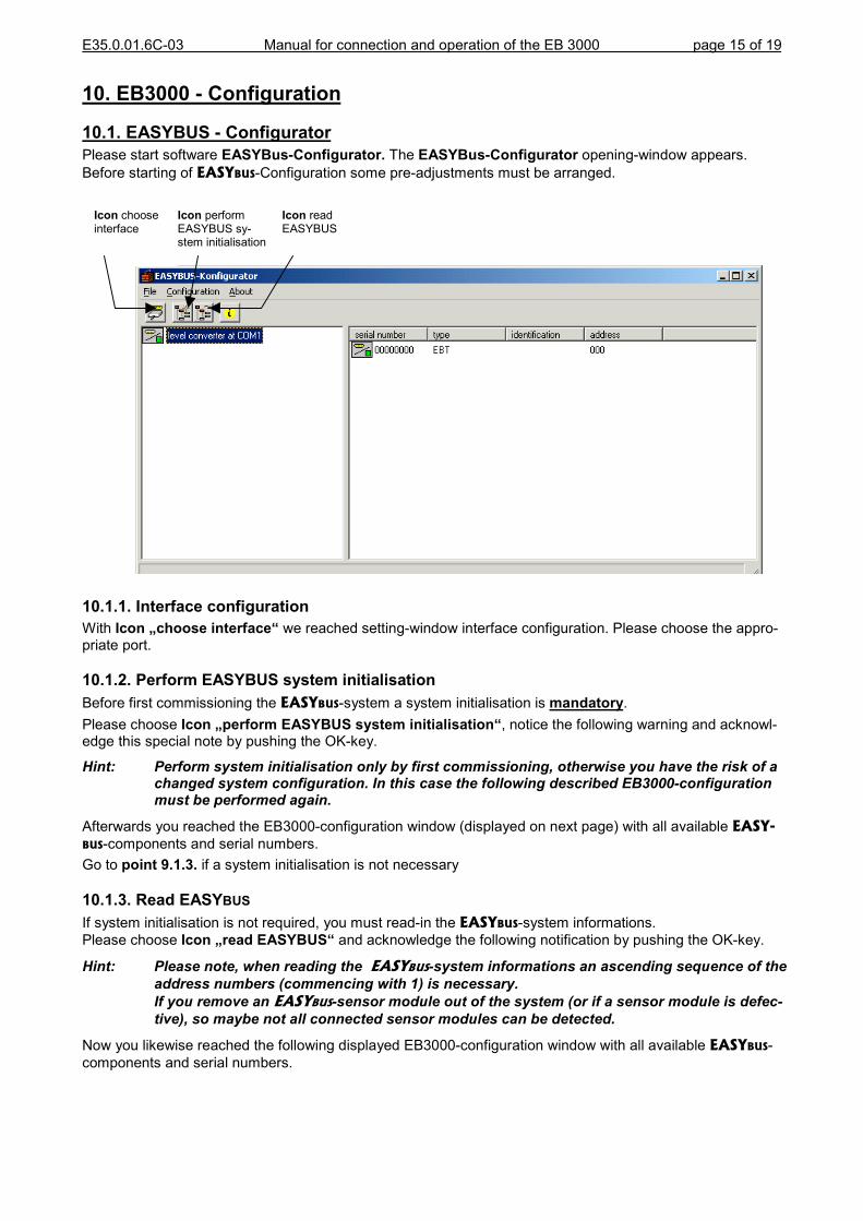
10. EB3000 - Configuration
10.1. EASYBUS - ConfiguratorPlease start software EASYBus-Configurator. The EASYBus-Configurator opening-window appears.Before starting of EASYBUS-Configuration some pre-adjustments must be arranged.
10.1.1With Icpriate p
10.1.2Before Pleaseedge th
Hint:
AfterwaBUS-comGo to p
10.1.3If systePlease
Hint:
Now yocompon
Icon chooseinterface
Icon performEASYBUS sy-stem initialisation
Icon readEASYBUS
. Interface configurationon �choose interface� we reached setting-window interface configuration. Please choose the appro-ort.
. Perform EASYBUS system initialisationfirst commissioning the EASYBUS-system a system initialisation is mandatory. choose Icon �perform EASYBUS system initialisation�, notice the following warning and acknowl-is special note by pushing the OK-key.
Perform system initialisation only by first commissioning, otherwise you have the risk of achanged system configuration. In this case the following described EB3000-configurationmust be performed again.
rds you reached the EB3000-configuration window (displayed on next page) with all available EASY-ponents and serial numbers.
oint 9.1.3. if a system initialisation is not necessary
. Read EASYBUSm initialisation is not required, you must read-in the EASYBUS-system informations. choose Icon �read EASYBUS� and acknowledge the following notification by pushing the OK-key.
Please note, when reading the EASYBUS-system informations an ascending sequence of theaddress numbers (commencing with 1) is necessary.If you remove an EASYBUS-sensor module out of the system (or if a sensor module is defec-tive), so maybe not all connected sensor modules can be detected.
u likewise reached the following displayed EB3000-configuration window with all available EASYBUS-ents and serial numbers.

E35.0.01.6C-03 Manual for connection and operation of the EB 3000 page 16 of 19
10.2. EB3000 - ConfigurationBy double-click on the EB3000-symbol on the device-overview a configuration window for theEB3000 opens.Now 5 register-tabs are available:- monitoring / display- control outputs- alarm- virtual channels- others
10.2.1. Tab: monitoring / display
EB3000-Symbol

E35.0.01.6C-03 Manual for connection and operation of the EB 3000 page 17 of 19
Here are 2 essential settings:
1) Allocation of the respective measurement channels - By measurement channel the EASYBUS-measurement channel with identification number is shown, which
is allocated to the respective channel. Until 20 channels can be listed. Measurement channels can also bemultiple listed and you can change the order of sequence as you like, so that by cyclic display (adjustable inthe control box on the top left-hand corner) any cyclic illustration flow is reachable.Reselection resp. modification of the left shown attached EASYBUS-measurement channels results via �dragand drop� or by activation of the right mouse button.Hint: �----� means that no measurement channel is allocated and this channel will not be monitored.
- By timeout the minimum updating-rate of the measurement channels in seconds will be specified (adjust-able between 8,0 and 50,0 seconds). If a updating of the measurement value of the respective measure-ment channel within the specified time-interval will not be possible (resp. overload of bus capacity), an errormessage will be displayed (timeout-error).Hint: For fully occupied measurement system choose timeout duration not too low, to avoid error messagesof the measurement system.
2) Predetermination of the display of individual channels - auxiliary display �channel description� for the respective channel shown in the auxiliary display. The
input of the �channel description� can be 2-digit, both letters and numbers are accepted.Hand-over of the channel description causes via click outside of the input folder resp.by pushing the enter-key. If the decimal point next to the channel description of theauxiliary display illuminates, cyclic operation is adjusted.Hint: please note, because of the restricted possibility of the 7-segment-display not allletters can be indicated.
- main display measurement value of the respective channel.For actualisation push button �refresh� beyond this column.
- LED�s you can allocate one or more �unit-LED�s� to each measurement channel. The 4 �unit-LED�s� are on the front side of the EB3000 on the right side next to the maindisplay. This settings are binary coded (for example by setting value 3 illuminatesLED 1+ LED 2). A click with the right mouse button on the respective value opensdialogue window �edit unit-LED�s�.
- display enduranceduration time in seconds, how long this channel will be indicated by cyclic display(max.25,5s).Hint: there is no relationship between display endurance and channel monitoring. Forexample by setting display endurance = 0 the respective channel will not be displayedbut he will be monitored.

E35.0.01.6C-03 Manual for connection and operation of the EB 3000 page 18 of 19
10.2.2. Tab: control outputs
Here is once again a listing of the measurement channels with allocation to the control outputs. A modifica-tion or reselection of the channels results via �drag and drop� or through manually input of the respectivechannel number.
- channel-nr. allocated measurement channel for this output.( The regulation function is assigned to this measuring value )
- switch.-on-point, switching points of the outputs (can also be modified via EB3000-device keys)switch.-off-point:
- delay minimum switching delay in seconds after a turn-off until output turns on again - function switching function of the outputs (in case of error, see chapter 6 � error codes).
The following switching functions are defined:0 � preference in case of error: switching output off1 � preference in case of error: switching output on
10.2.3. Tab: alarm
Here �edit� Adjus- m- m- a
you can examine and redefine the adjusted alarm limits for each measurement channel. By pushing thebutton next to the respective measurement channel you reached a second dialogue window.table are following values:inimum alarm limit (alarm min)aximum alarm limit (alarm max)
larm delay (declaration in minutes)

E35.0.01.6C-03 Manual for connection and operation of the EB 3000 page 19 of 19
10.2.4. Tab: virtual channels
Here you can select functions for both �virtual channels� for programming into the EB3000.If the desired function is not available, please visit our homepage. Here additional functions for download areavailable.After download copy transferred datafiles easily into directory �EB3CV� inside of the configurator-installationdirectory. By the next start of register-tab �virtual channels� the function will be available for selection.
10.2.5. Tab: others
Here you have the ability to determine a device identifier and a node address. Furthermore you can deacti-vate timeout monitoring and clear alarms. Additionally you can see the version number of the EB3000.


![DPE RHO Visual Assessment Report 170614 - Amazon S3...J=CKFQR@A Eb`a Eb`a ni Ji\]lXn] Ji\]lXn] Ji\]lXn] ni IiqIiq K]`eb`bZe] Eb`a Eb`a bgjX[n Eb`a FgjX[n Ji\]lXn] Eb`a Ji\]lXn] Eb`a](https://static.fdocuments.us/doc/165x107/6127f826dfe2eb21db79cba4/dpe-rho-visual-assessment-report-170614-amazon-s3-jckfqra-eba-eba-ni-jilxn.jpg)