Eaton HFX Product Family Installation and Operation Manual ...
60
Eaton HFX Product Family Installation and Operation Manual HFX Product Line
-
Upload
truonghuong -
Category
Documents
-
view
230 -
download
1
Transcript of Eaton HFX Product Family Installation and Operation Manual ...

Eaton HFX Product Family Installation and Operation ManualHFX Product Line

EATON HFX Product Family Installation and Operation Manual E-ELCL-II002-E1 November 20142
Warning
Before beginning installation of this product: Read and follow all installation instructions. Please contact Eaton immediately if you have any questions.
Note: This manual was written with great care and precision. However, since the potential for error exists, we can provide no assurance of the absolute accuracy of its contents.
Warranty
In order to consistently bring you the highest quality, full featured products, we reserve the right to change our specifications and designs at any time.
A limited warranty is given with these Eaton products. Please see our website for details. http://www.eaton.com/Eaton/ProductsServices/Hydraulics/WarrantyTermsConditions/PCT_612027
!!
HFX Product Family General Information
EATON HFX Product Family Installation and Operation Manual E-ELCL-II002-E1 November 2014 3
Table of Contents
Section Description Page No.
1.0 INTRODUCTION 62.0 TECHNICAL SPECIFICATIONS 73.0 KEY FEATURES 94.0 SAFETY CONSIDERATIONS 95.0 APPLICATION 96.0 HARDWARE DESCRIPTION 97.0 SOFTWARE DESCRIPTION 128.0 SERVICE TOOL INSTALLATION AND GETTING STARTED 128.1 Driver Installation 128.2 Install The HFX Service Tool Software 128.3 Launch The HFX Service Tool 129.0 FIRMWARE 139.1 Install The Firmware 1310.0 PRO-FX-CONTROL 1310.1 Driver Installation 1310.2 Install Pro-FX Control 1310.3 Install The Pro-FX Control Gateway File for HFX 1310.4 Install The HFX Target Definitions 1411.0 GETTING STARTED 1411.1 Create Your First Project 1411.2 Connect And Program Your Controller 1412.0 FUNCTIONALITY & BASIC OPERATION 1512.1 Controller Startup 1512.2 Sleep Mode (Time Delay Operation) 1512.3 Task Configuration 1512.4 Watch Dog Operation 1612.5 Controller Memory 1712.6 Remanant Variables 1712.7 File System Operation 1812.8 LED Operation 1813.0 INSTALLING THE CONTROLLER 1813.1 Product Dimensions 1813.2 Recommended Wiring 1914.0 ELECTRICAL CONNECTION INFORMATION 2014.1 Wiring Pin Out 2015.0 CONFIGURATION 2215.1 System Confiruration 2215.2 Input Modes 2315.3 Analog Configuration 2316.0 ANALOG INPUT CIRCUIT (PASSIVE REPRESENTATION) 2516.1 Thermistor 2716.2 Frequency Configuration 2717.0 FREQUENCY INPUT CIRCUIT (PASSIVE REPRESENTATION) 2917.1 Output Mode 2917.2 H-Bridge 32
EATON HFX Product Family Installation and Operation Manual E-ELCL-II002-E1 November 20144
Section Description Page No.
18.0 OUTPUT CIRCUIT (PASSIVE REPRESENTATION) 3318.1 Overcurrent Shutdown 3319.0 PWM 3319.1 What Is PWM? 3320.0 CAN & SAE J1939 3521.0 INPUT STATUS, FEEDBACK AND DIAGNOSIS 3521.1 Block Diagram 3722.0 TESTING & VALIDATION 4123.0 SERVICE TOOL 4224.0 FAULT CONDITIONS 4725.0 APPENDIX 5825.1 Supported & Unsupported CODESYS Features 5825.2 Supported 5825.3 Not Supported 5826.0 DEVICE COMMUNICATION TROUBLESHOOTING 5927.0 DEVICE RECOVERY 59
Table of Contents

EATON HFX Product Family Installation and Operation Manual E-ELCL-II002-E1 November 2014 5
(THIS PAGE INTENTIONALLY LEFT BLANK)

EATON HFX Product Family Installation and Operation Manual E-ELCL-II002-E1 November 20146
HFX Product Family
1.0 INTRODUCTION
The Eaton HFX product family is a series of advanced, CAN-based controllers for use with mobile and industrial equipment. Using a standardized IEC 61131-3 programming environment, these controllers enable functional control over electrically operated components within a variety of applications (e.g. agricultural, construction, material handling).It is recommended that an individual have experience with control engineering and programming within the CODESYS 3.5 software environment before using this hardware.
The HFX product family is optimized for reliable operation in severe environments, possessing IP and temperature ratings that exceed existing solutions from competitors. HFX controllers employ several advanced technologies (e.g. I/O with variable configuration architecture), enabling simple management and enhancing both ease of use and functionality.These controllers are intended as both a standalone solution, or as the centerpiece to a complete control system that can include other CAN-based devices such as displays and keypads.
Key Acronyms and Abbreviations CODESYS Controller Development SystemFW FirmwareHW HardwareIDE Integrated Development EnvironmentIP Intellectual PropertyMIL Malfunction Indicator LampPOU Program Organization UnitPWM Pulse Width ModulationRTS Run Time SystemSW Software
EATON HFX Product Family Installation and Operation Manual E-ELCL-II002-E1 November 2014 7
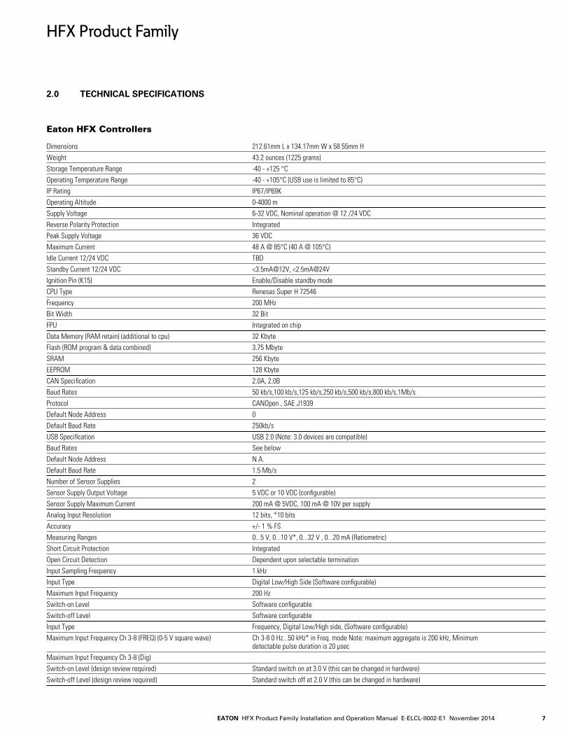
2.0 TECHNICAL SPECIFICATIONS
Eaton HFX Controllers Dimensions 212.61mm L x 134.17mm W x 58.55mm HWeight 43.2 ounces (1225 grams)Storage Temperature Range -40 - +125 °C Operating Temperature Range -40 - +105°C (USB use is limited to 85°C) IP Rating IP67/IP69K Operating Altitude 0-4000 mSupply Voltage 6-32 VDC, Nominal operation @ 12 /24 VDCReverse Polarity Protection IntegratedPeak Supply Voltage 36 VDCMaximum Current 48 A @ 85°C (40 A @ 105°C)Idle Current 12/24 VDC TBDStandby Current 12/24 VDC <3.5mA@12V, <2.5mA@24VIgnition Pin (K15) Enable/Disable standby mode CPU Type Renesas Super H 72546Frequency 200 MHzBit Width 32 BitFPU Integrated on chipData Memory (RAM retain) (additional to cpu) 32 KbyteFlash (ROM program & data combined) 3.75 MbyteSRAM 256 Kbyte EEPROM 128 KbyteCAN Specification 2.0A, 2.0BBaud Rates 50 kb/s,100 kb/s,125 kb/s,250 kb/s,500 kb/s,800 kb/s,1Mb/sProtocol CANOpen , SAE J1939 Default Node Address 0Default Baud Rate 250kb/sUSB Specification USB 2.0 (Note: 3.0 devices are compatible)Baud Rates See belowDefault Node Address N.A.Default Baud Rate 1.5 Mb/sNumber of Sensor Supplies 2Sensor Supply Output Voltage 5 VDC or 10 VDC (configurable)Sensor Supply Maximum Current 200 mA @ 5VDC, 100 mA @ 10V per supplyAnalog Input Resolution 12 bits, *10 bitsAccuracy +/- 1 % FSMeasuring Ranges 0...5 V, 0...10 V*, 0...32 V , 0...20 mA (Ratiometric) Short Circuit Protection IntegratedOpen Circuit Detection Dependent upon selectable terminationInput Sampling Frequency 1 kHzInput Type Digital Low/High Side (Software configurable)Maximum Input Frequency 200 HzSwitch-on Level Software configurable Switch-off Level Software configurableInput Type Frequency, Digital Low/High side, (Software configurable)Maximum Input Frequency Ch 3-8 (FREQ) (0-5 V square wave) Ch 3-8 0 Hz...50 kHz* in Freq. mode Note: maximum aggregate is 200 kHz, Minimum detectable pulse duration is 20 μsecMaximum Input Frequency Ch 3-8 (Dig) Switch-on Level (design review required) Standard switch on at 3.0 V (this can be changed in hardware)Switch-off Level (design review required) Standard switch off at 2.0 V (this can be changed in hardware)
HFX Product Family

EATON HFX Product Family Installation and Operation Manual E-ELCL-II002-E1 November 20148
Input Type Variable reluctance (Software configurable)Maximum Input Frequency Ch 1-2 (FREQ) (0-5 V square or sine wave) 0Hz...25kHz* Note: maximum aggregate is 200 kHz, Note: phase and duty cycle are not supported by these inputs minimum detectable pulse duration is 20 μsecSwitch-on Level Selectable as 2.2 V or self adaptive (input device changes voltage with frequency) Switch-off Level Selectable as 0.0 V or 1.0 VOutput Type High Side (Software configurable)Max Amperage 2ADiagnostics Open/Short circuit protectionOutput Type Low/High side, H-Bridge (Software configurable)Max Amperage 4ADiagnostics Open/Short circuit protectionType PWMi, High side (Software configurable)Max Amperage 2ADiagnostics Open/Short Circuit ProtectionPWM Frequency 50 – 2 kHzDither Frequency ConfigurableDither Amplitude ConfigurableControl Range 0.05 - 2 AControl Resolution 1 mAFly Back Protection IntegratedDuty Cycle Resolution .01% @ 250 HzType PWMi, High Side (Software configurable)Max Amperage 4ADiagnostics Open/Short circuit protectionPWM Frequency 50 – 500 HzDither Frequency ConfigurableDither Amplitude ConfigurableControl Range 0.05 - 4 AControl Resolution 1.5 mAFly Back Protection IntegratedDuty Cycle Resolution .01% @ 250HConnector Manufacturer Deutsch Inc.Model DRC23-40PA & DRC23-40PBContact Surface Nickel platedConnector Assembly Parts List Mating connector DRC26-40SA & DRC26-40SB, size 20 solid contacts P/N 0460-202-20141 intended for 20AWG wire, 460-010-20141 intended for 16-18 AWG wire, size 20 stamped and formed contacts P/N 1060-20-0122(nickel plated), sealing plug P/N 0413-204-2005Tooling Manufacturer DeutschHand Tool Part Number Solid contacts: Service crimper: HST-1561 Production crimper(ratcheting): HDT-48-00 Stamped contacts: DTT-20-00Die Part Number N/AContact Removal Tool P/N 0411-240-2005
HFX Product Family

EATON HFX Product Family Installation and Operation Manual E-ELCL-II002-E1 November 2014 9
3.0 KEY FEATURES
• Robust, compact, fully sealed & potted cast aluminum construction
• Completely protected outputs (thermal and overcurrent)
• Reverse polarity protection
• Up to 24 multifunction inputs, depending on model
• Up to 24 multifunction outputs, depending on model
• Diagnostic feedback for short circuit & wire break on all outputs
• Use of proven Deutsch connectors for rigorous IP protection
• Programmable via USB for simple connection to PC
• Three CAN ports
• Sleep input for improved power management
• Regulated supply for sensors
• Three programmable LED status indicators
4.0 SAFETY CONSIDERATIONS
Note: This operating and installation manual is intended for use by a competent programmer, electrician, technician, or engineer. The instructions included in this manual should be read and kept as a reference document prior to initial controller installation and use. Incorrect operation of these controllers can present a significant threat to both individuals and equipment. In the event of an equipment break down, do not attempt to repair the controller as there are no user serviceable parts inside the enclosure. Any evidence of tampering will invalidate the warranty.
5.0 APPLICATION
This operating and installation manual should be used in conjunction with the online help provided with the Pro-FX Control 1.1 development environment. Together, this information should form a basis for the simple configuration of the controller and the creation of programs specific to your application needs. Proper operation of the controller is dependent on the program that is created and ultimately downloaded to the hardware, therefore extensive testing is required.Customers programming the controller possess the responsibility of ensuring that both the hardware and software performs as intended with their applications.
Note: That each controller within the HFX product family requires the installation of hardware-specific firmware, description files and libraries before initial use in the application environment.
6.0 HARDWARE DESCRIPTION
The Eaton HFX product line consists of four controller models (HFX12m, HFX20m, HFX32m, and HFX48m), each possessing a unique number of I/O. The HFX12m/HFX20m (pictured below) and HFX32m/HFX48m (pictured below) both share common housings.
Each of these units is designed to function over an extended operating range of supply voltage, from 6 – 32 VDC.
HFX12m/HFX20m
HFX32m/HFX48m
The three integrated CAN ports on these units support CAN 2.0B, the first of which also possesses a software configurable termination. Both SAE J1939 and CANOpen stacks are available in the software development environment.Additionally, the CANLayer2 software library is available for use with CAN bus.
HFX controllers are programmed via a standard USB port. The gateway from a user’s computer automatically detects the hardware, eliminating the need to manually assign a COM port to the unit.The two regulated outputs (sensor supplies) can be configured individually for either 5 or 10 V operation.
HFX Product Family

EATON HFX Product Family Installation and Operation Manual E-ELCL-II002-E1 November 201410
The table below represents an I/O overview of the various HFX controller models. HFX48m HFX32m HFX20m HFX12m Controller Model (24 I/O) (16 I/O) (10 I/O) (6 I/O)
Total Outputs 24 16 10 6 Total 2 A channels 16 10 6 4 Number of channels supporting function PWM 16 10 6 4 PWMi 16 10 6 4 High Side output 16 10 6 4 Total 4 A channels 8 6 4 2 Number of channels supporting function PWM 8 6 4 2 PWMi 8 6 4 2 High Side output 8 6 4 2 Low Side output 8 6 4 2 H-Bridge pair 4 3 2 1
HFX48m HFX32m HFX20m HFX12m Controller Model (24 I/O) (16 I/O) (10 I/O) (6 I/O)
Total Inputs 24 16 10 6 Total frequency channels 8 6 4 2 Number of channels supporting function High frequency 8 6 4 2 Variable reluctance 2 2 2 2 High Side input 8 6 4 2 Low Side input 8 6 4 2 Total analog channels 16 10 6 4 Number of channels supporting function 0 - 5 V input 16 10 6 4 0 - 10 V input 16 10 6 4 0 - 32 V input 16 10 6 4 4 - 20 mA input 16 10 6 4 High Side input 16 10 6 4 Low Side input 16 10 6 4 Thermistor 16 10 6 4
HFX Product Family
EATON HFX Product Family Installation and Operation Manual E-ELCL-II002-E1 November 2014 11
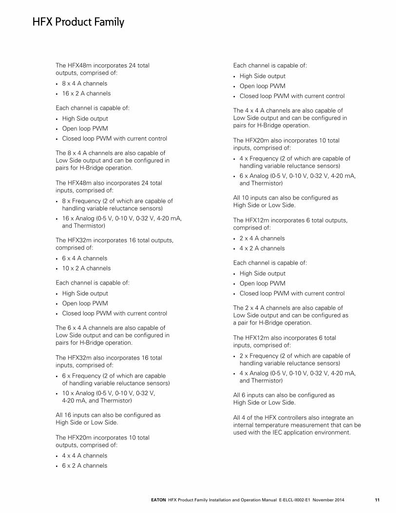
The HFX48m incorporates 24 total outputs, comprised of:
• 8 x 4 A channels
• 16 x 2 A channels
Each channel is capable of:
• High Side output
• Open loop PWM
• Closed loop PWM with current control
The 8 x 4 A channels are also capable of Low Side output and can be configured in pairs for H-Bridge operation.
The HFX48m also incorporates 24 total inputs, comprised of:
• 8 x Frequency (2 of which are capable of handling variable reluctance sensors)
• 16 x Analog (0-5 V, 0-10 V, 0-32 V, 4-20 mA, and Thermistor)
The HFX32m incorporates 16 total outputs, comprised of:
• 6 x 4 A channels
• 10 x 2 A channels
Each channel is capable of:
• High Side output
• Open loop PWM
• Closed loop PWM with current control
The 6 x 4 A channels are also capable of Low Side output and can be configured in pairs for H-Bridge operation.
The HFX32m also incorporates 16 total inputs, comprised of:
• 6 x Frequency (2 of which are capable of handling variable reluctance sensors)
• 10 x Analog (0-5 V, 0-10 V, 0-32 V, 4-20 mA, and Thermistor)
All 16 inputs can also be configured as High Side or Low Side.
The HFX20m incorporates 10 total outputs, comprised of:
• 4 x 4 A channels
• 6 x 2 A channels
Each channel is capable of:
• High Side output
• Open loop PWM
• Closed loop PWM with current control
The 4 x 4 A channels are also capable of Low Side output and can be configured in pairs for H-Bridge operation.
The HFX20m also incorporates 10 total inputs, comprised of:
• 4 x Frequency (2 of which are capable of handling variable reluctance sensors)
• 6 x Analog (0-5 V, 0-10 V, 0-32 V, 4-20 mA, and Thermistor)
All 10 inputs can also be configured as High Side or Low Side.
The HFX12m incorporates 6 total outputs, comprised of:
• 2 x 4 A channels
• 4 x 2 A channels
Each channel is capable of:
• High Side output
• Open loop PWM
• Closed loop PWM with current control
The 2 x 4 A channels are also capable of Low Side output and can be configured as a pair for H-Bridge operation.
The HFX12m also incorporates 6 total inputs, comprised of:
• 2 x Frequency (2 of which are capable of handling variable reluctance sensors)
• 4 x Analog (0-5 V, 0-10 V, 0-32 V, 4-20 mA, and Thermistor)
All 6 inputs can also be configured as High Side or Low Side.
All 4 of the HFX controllers also integrate an internal temperature measurement that can be used with the IEC application environment.
HFX Product Family

EATON HFX Product Family Installation and Operation Manual E-ELCL-II002-E1 November 201412
7.0 SOFTWARE DESCRIPTION
Software for the HFX family of controllers is provided in the form of the HFX Platform Support Package. This is distributed as a .zip file and contains the following elements:
• Firmware files (MOT files): A separate file is provided for each HFX controller model.
• Device description package for Pro-FX Control: The HFX package file can be installed using the Pro-FX Control Package Manager.Once it is installed, any of the HFX devices can be used within Pro-FX Control.
• HFX Service Tool: Setup.exe in the Service Tool folder is the installation file.
• Gateway file: Gateway.cfg defines how Pro-FX Control connects to the HFX device.
• HFX USB Driver: Pro-FX Control connects to the HFX using USB. This is the driver to support that connection.
• ECOM USB Driver: The Pro-FX Configure HFX Service Tool connects to the HFX over CAN using the ECOM device. This is the driver for that device.
When updating an existing HFX Support Package, it is necessary to update each of the above elements except for the USB drivers, which do not need to be updated unless explicitly mentioned in a given release.
8.0 SERVICE TOOL - INSTALLATION AND GETTING STARTED
8.1 Driver Installation
8.1.1 Before using the HFX Service Tool, it is necessary to install the driver for the ECOM USB/CAN interface device.Prior to installing the driver, make sure that all ECOM devices are detached from your computer and that all programs are closed.
8.1.2 Run the ECOM driver installation application Driver_Setup_C3.1.0.15.exe, located in the Service Tool folder of the HFX Support Package.
8.1.3 Proceed with the installation by following the onscreen instructions.
8.1.4 Once installation has completed, connect the ECOM device and Windows will complete the installation for the hardware and port.
8.2 Install the HFX Service Tool Software
8.2.1 Run the HFX Service Tool installation file setup.exe in the Service Tool folder of the HFX Support Package.
8.3 Launch the HFX Service Tool
8.3.1 Launch Pro-FX.
8.3.2 Select Pro-FX Configure in the Pro-FX Launcher
HFX Product Family

EATON HFX Product Family Installation and Operation Manual E-ELCL-II002-E1 November 2014 13
8.3.3 Select the HFX Service Tool.
8.3.4 You may be prompted for a password.The password can be found in the file ‘Password.txt’, located in the Service Tool folder of the HFX support package.You have the option to select ‘Save password and S/N’, which stores the password for the next time the software is used.
9.0 FIRMWARE
9.1 Install the Firmware
9.1.1 HFX units are shipped blank, with no firmware loaded. Prior to first use, it is necessary to load firmware to the HFX.
9.1.2 Launch the HFX Service Tool if it is not already open. On the main page of the service tool select File->Reprogram Firmware.
9.1.3 Select the appropriate firmware to load based on the model of the controller intended for use.
9.1.4 The firmware should complete the installation process. If the wrong firmware has been selected, the software will provide a prompt which indicates that the firmware does not match the controller hardware. If this occurs, verify that the correct firmware was selected. The software should then load on the controller and complete installation. You should now be ready to proceed with the application software installation.
10.0 PRO-FX CONTROL
10.1 Driver Installation
10.1.1 Pro-FX Control connects to the HFX controller using a computer’s USB port. Before using Pro-FX Control to connect to the HFX unit, it is necessary to install the HFX USB Driver. Run the file ‘USBDriverInstaller.exe’ in the Gateway folder of the HFX Platform Support Package.
10.1.2 Plug in the USB port connection from a computer to the HFX connector and wait for Windows to successfully load the drivers.
10.2 Install Pro-FX Control
10.2.1 Install Pro-FX Control if it is not already installed.
HFX Product Family

EATON HFX Product Family Installation and Operation Manual E-ELCL-II002-E1 November 201414
10.3 Install the Pro-FX Control Gateway File for HFX
10.3.1 Copy the file gateway.cfg from the gateway directory of the HFX Platform Support Package over the existing version located at ProgramFiles (x86)\3S CODESYS\GatewayPLC.This file configures the USB port and baud rate that will be used by Pro-FX Control when connecting to HFX.
10.3.2 In order for the gateway changes to take effect, you must stop and restart the gateway. This can be done by right-clicking on the gateway icon in your system tray bar next to the clock.
10.4 Install the HFX Target Definitions
10.4.1 Launch Pro-FX Control and select Tools->Package Manager.
Note: That it is necessary to run Pro-FX Control with Administrator privileges to complete this step.
10.4.2 Click the "Install..." button.
10.4.3 Highlight the HFX package file and select open.
10.4.4 Follow the prompts to finish the installation. Close the Package Manager.
11.0 GETTING STARTED
11.1 Create your First Project
11.1.1 Click File->New Project.
11.1.2 Select "Standard Project". Click "OK".
11.1.3 Select the appropriate HFX device and I/O count for the controller you will be using for your project. Click OK.
11.2 Connect and Program your Controller
11.2.1 Connect the HFX controller to the USB port of your computer via the 6-pin Deutsch connector.
11.2.2 Ensure that the unit is powered-up properly by verifying that LED A is green.
11.2.3 In the Pro-FX Control "Devices" tree view, double click on the "Device".
11.2.4 Click on the "Communication Settings" tab.
11.2.5 Click on the "Gateway-1" and then click "Scan Network".
11.2.6 One HFX should appear. Click on it and select "Set active Path". If you have problems with this step, please see the troubleshooting steps in Appendix A.
11.2.7 Select "Online->Login" and then acknowledge any prompts that are displayed.
11.2.8 Click "Debug->Start".
11.2.9 You have now programmed an empty project to your HFX controller and are connected for the first time. LED A should be flashing on your controller which indicates that there is an application currently running on your controller.
HFX Product Family
EATON HFX Product Family Installation and Operation Manual E-ELCL-II002-E1 November 2014 15
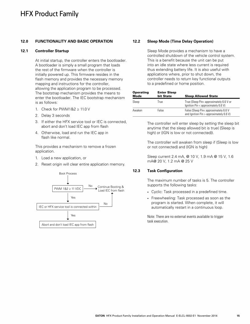
12.0 FUNCTIONALITY AND BASIC OPERATION
12.1 Controller Startup
At initial startup, the controller enters the bootloader. A bootloader is simply a small program that loads the rest of the firmware when the controller is initially powered up. This firmware resides in the flash memory and provides the necessary memory mapping and instructions for the controller, allowing the application program to be processed. The bootstrap mechanism provides the means to enter the bootloader. The IEC bootstrap mechanism is as follows:
1. Check for PWM1&2 ≥ 11.0 V
2. Delay 3 seconds
3. If either the HFX service tool or IEC is connected, abort and don’t load IEC app from flash
4. Otherwise, load and run the IEC app in flash like normal.
This provides a mechanism to remove a frozen application.
1. Load a new application, or
2. Reset origin will clear entire application memory.
Boot Process
Continue Booting & Load IEC from flash
Yes
No
No
PWM 1&2 ≥ 11 VDC
IEC or HFX service tool is connected within
Yes
Abort and don’t load IEC app from flash
12.2 Sleep Mode (Time Delay Operation)
Sleep Mode provides a mechanism to have a controlled shutdown of the vehicle control system.This is a benefit because the unit can be put into an idle state where less current is required thus extending battery life. It is also useful with applications where, prior to shut down, the controller needs to return key functional outputs to a predefined or home position.
Operating Enter Sleep Mode bit State Sleep Allowed State
Sleep True True (Sleep Pin> approximately 6.6 V or Ignition Pin < approximately 6.6 V)Awaken False False (Sleep Pin< approximately 6.6 V and Ignition Pin > approximately 6.6 V)
The controller will enter sleep by setting the sleep bit anytime that the sleep allowed bit is true( Sleep is high or IGN is low or not connected).
The controller will awaken from sleep if Sleep is low or not connected and IGN is high
Sleep current 2.4 mA, @ 10 V, 1.9 mA @ 15 V, 1.6 mA@ 20 V, 1.2 mA @ 25 V
12.3 Task Configuration
The maximum number of tasks is 5. The controller supports the following tasks:
• Cyclic: Task processed in a predefined time.
• Freewheeling: Task processed as soon as the program is started. When complete, it will automatically restart in a continuous loop.
Note: There are no external events available to trigger task execution.
HFX Product Family

EATON HFX Product Family Installation and Operation Manual E-ELCL-II002-E1 November 201416
12.4 Watchdog Operation
Watchdogs are present to provide an indication that something has gone wrong. Systems that are programmable can hang for a number of different reasons. One of the most common is the execution of an infinite loop due to a programming logic error This type of failure prevents any of the other code from executing. Also, if an unusual number of interrupts arrives during a single cycle of the loop this can prevent the main loop from having sufficient time to execute. Another possibility is a failure in hardware that causes a constant reset.
Each controller has an internal hardware watchdog that is continuously running in the background to
monitor for a system malfunction. This watchdog is not user serviceable and is not visible to the user. It will trigger in the event of a task timeout and can only be reset through a hard reset of the controller, which means that the user must connect the service tool or IEC programming tool to the controller, tie PWM 1 & 2 to supply voltage, and then power up the unit. This will prevent the IEC application code from loading.
Each controller also features a second watchdog, which monitors the Pro-FX Control runtime system with a default value of 2 seconds and recommendation to be set above a minimum 100 ms. This is user configurable via the System Config Configuration tab (see below screen).
Note: That this watchdog is reset using the same protocol used to reset the internal hardware watchdog.
Pro-FX Control also has a watchdog that monitors specific tasks; the time is user configurable via the Task Configuration/MainTask tab (see below screen). For additional details see Pro-FX Control online help. It is typically reset by resetting an associated fault.
HFX Product Family

EATON HFX Product Family Installation and Operation Manual E-ELCL-II002-E1 November 2014 17
HFX Product Family
12.5 Controller Memory
The controller utilizes an advanced superscalar 32 Bit processor operating at 200 MHz. The memory is arranged into the following areas:
• ROM Flash 3.75 Mbyte (1.75 Mbyte reserved for IEC application)
• EEPROM128 kbyte reserved for internal use i.e. firmware/bootloader
• RAM 256 kbyte
• MRAM 32 kbyte (24 kbyte user accessible file-system + 4kbyte redundant retain)
12.6 Remanant Variables
These are variables that can retain their value throughout the usual program run period. They are declared as 'Retain Variables', or even more stringent, as 'Persistent Variables'. For each case, a separate memory area is used.
The declaration determines the degree of "resistance" for a remanent variable in the case of resets, downloads or a reboot of the PLC. In applications, the combination of both remanent flags will be required.
The following table indicates how variables behave. VAR PERSISTENT/ VAR RETAIN PERSISTENT/ Online VAR VAR RETAIN VAR PERSISTENT RETAIN
Power cycle - X XReset warm <application> - X XReset cold <application> - - XReset origin <application> - - -Download <application> - - X
12.7 File System Operation
HFX provides a file system in MRAM to store additional information persistent through power cycles and application download. MRAM is faster than Flash memory and EEPROM and allows a virtually unlimited number of write cycles.
Using a file system for this purpose allows the most efficient use of memory and provides the advantage of being able to work with configuration files using the file system viewer in Pro-FX Control. Due to the speed and byte-level access of MRAM, interacting with this file system is extremely fast.
The following file operations are supported:
• SysFileClose
• SysFileCopy
• SysFileDelete
• SysFileEOF
• SystFileGetName
• SystFileGetPath
• SysFileGetPos
• SysFileGetSize
• SysFileGetSizeByHandle
• SysFileGetStatus
• SysFileOpen
• SysFileRead
• SysFileRename
• SysFileSetPos
• SysFileWrite
Details on using these functions can be found in the Pro-FX Control Online Help system.
EATON HFX Product Family Installation and Operation Manual E-ELCL-II002-E1 November 201418
HFX Product Family
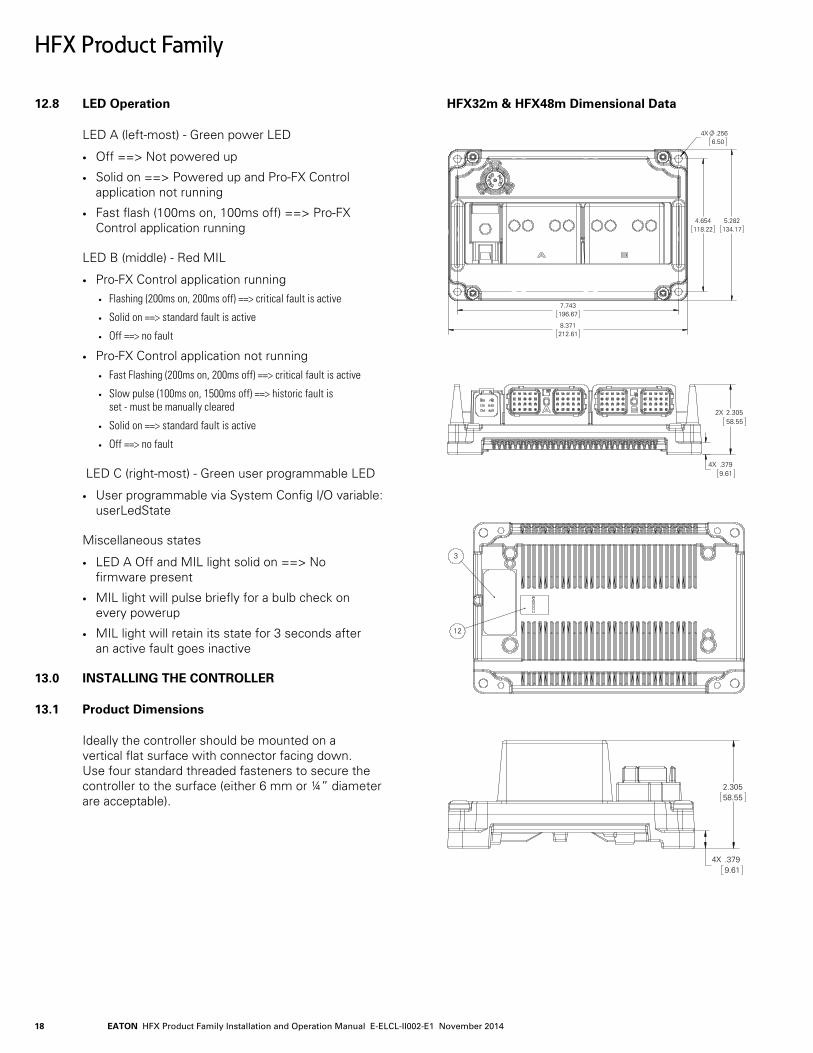
12.8 LED Operation
LED A (left-most) - Green power LED
• Off ==> Not powered up
• Solid on ==> Powered up and Pro-FX Control application not running
• Fast flash (100ms on, 100ms off) ==> Pro-FX Control application running
LED B (middle) - Red MIL
• Pro-FX Control application running• Flashing (200ms on, 200ms off) ==> critical fault is active
• Solid on ==> standard fault is active
• Off ==> no fault
• Pro-FX Control application not running• Fast Flashing (200ms on, 200ms off) ==> critical fault is active
• Slow pulse (100ms on, 1500ms off) ==> historic fault is set - must be manually cleared
• Solid on ==> standard fault is active
• Off ==> no fault
LED C (right-most) - Green user programmable LED
• User programmable via System Config I/O variable: userLedState
Miscellaneous states
• LED A Off and MIL light solid on ==> No firmware present
• MIL light will pulse briefly for a bulb check on every powerup
• MIL light will retain its state for 3 seconds after an active fault goes inactive
13.0 INSTALLING THE CONTROLLER
13.1 Product Dimensions
Ideally the controller should be mounted on a vertical flat surface with connector facing down. Use four standard threaded fasteners to secure the controller to the surface (either 6 mm or ¼” diameter are acceptable).
HFX32m & HFX48m Dimensional Data
4X .2566.50
4.654118.22
7.743196.67
5.282134.17
8.371212.61
2X 2.30558.55
4X .3799.61
3
12
4X .3799.61
2.30558.55
EATON HFX Product Family Installation and Operation Manual E-ELCL-II002-E1 November 2014 19
HFX Product Family
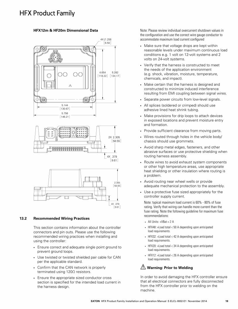
HFX12m & HF20m Dimensional Data
4X .2566.50
4.654118.22
5.144130.67
5.756146.21
5.282134.17
4X .3799.61
2X 2.30558.55
4X .3799.61
2.30558.55
13.2 Recommended Wiring Practices
This section contains information about the controller connectors and pin outs. Please use the following recommended wiring practices when installing and using the controller:
• Ensure correct and adequate single point ground to prevent ground loops.
• Use twisted or twisted shielded pair cable for CAN per the applicable standard.
• Confirm that the CAN network is properly terminated using 120Ω resistors.
• Ensure the appropriate sized conductor cross section is specified for the intended load current in the harness design.
Note: Please review individual overcurrent shutdown values in the configuration and use the correct wire gauge conductor to accommodate maximum load current configured
• Make sure that voltage drops are kept within reasonable levels under maximum continuous load conditions e.g. 1 volt on 12-volt systems and 2 volts on 24-volt systems.
• Verify that the harness is constructed to meet the needs of the application environment (e.g. shock, vibration, moisture, temperature, chemicals, and impact).
• Make certain that the harness is designed and constructed to minimize induced interference resulting from EMI coupling between signal wires.
• Separate power circuits from low-level signals.
• All splices (soldered or crimped) should use adhesive lined heat shrink tubing.
• Make provisions for drip loops to attach devices in exposed locations and prevent moisture entry and formation.
• Provide sufficient clearance from moving parts.
• Wires routed through holes in the vehicle body/chassis should use grommets.
• Avoid sharp metal edges, fasteners, and other abrasive surfaces or use protective shielding when routing harness assembly.
• Route wires to avoid exhaust system components or other high temperature areas, use appropriate heat shielding or other insulation where routing is a problem.
• Avoid routing near wheel wells or provide adequate mechanical protection to the assembly.
• Use a protective fuse sized appropriately for the controller supply current.
Note: typical maximum load current is 60% - 80% of fuse rating. Verify that wiring can handle more current than the fuse rating. Note the following guideline for maximum fuse recommendations:
• All Units: +VBat = 2 A
• HFX48 :+Load total < 50 A depending upon anticipated load requirements.
• HFX32: +Load total < 42 A depending upon anticipated load requirements.
• HFX20: +Load total < 34 A depending upon anticipated load requirements.
• HFX12: +Load total < 26 A depending upon anticipated load requirements.
! Warning: Prior to Welding
In order to avoid damaging the HFX controller ensure that all electrical connectors are fully disconnected from the HFX controller prior to welding on the machine.
EATON HFX Product Family Installation and Operation Manual E-ELCL-II002-E1 November 201420
HFX Product Family
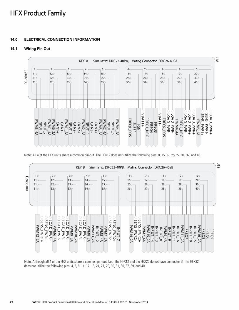
14.0 ELECTRICAL CONNECTION INFORMATION
14.1 Wiring Pin Out
1
2111
31
2
2212
32
3
2313
33
4
2414
34
5
2515
35
6
2616
36
7
2717
37
8
2818
38
9
2919
39
10
3020
40
KEY A Similiar to: DRC23-40PA, Mating Connector: DRC26-40SA
J1A
E2486100
CAN
1+CA
N1-
CAN
2+CA
N2-
CAN
3+CA
N3-
FREQ
1_POS
FREQ
1_NE
G
FREQ
2_POS
FREQ
2_NE
G
FREQ
3FR
EQ4
INP
UT_1
INP
UT_2
INP
UT_3
INP
UT_4
INP
UT_5
INP
UT_6
PWM
1_2A
PWM
2_2A
PWM
3_2A
PWM
4_2A
PWM
5_2A
PWM
6_2APW
M1_4A
PWM
2_4A
PWM
3_4A
PWM
4_4A
IGN
SLEEP
VBA
TT-
SENS
_PWR1+
SENS
_PWR1-
VBA
TT+
LOA
D_PW
R+LO
AD
_PWR+
LOA
D_PW
R+
LOA
D_PW
R-
LOA
D_PW
R-
LOA
D_PW
R-
Note: All 4 of the HFX units share a common pin-out. The HFX12 does not utilize the following pins: 8, 15, 17, 25, 27, 31, 32, and 40.
1
2111
31
2
2212
32
3
2313
33
4
2414
34
5
2515
35
6
2616
36
7
2717
37
8
2818
38
9
2919
39
10
3020
40
KEY B Similiar to: DRC23-40PB, Mating Connector: DRC26-40SB
J1B
E2486100
FREQ
5FR
EQ6
FREQ
7
FREQ
8
INP
UT_7
INP
UT_8
INP
UT_9
INP
UT_10
INP
UT_11
INP
UT_12
INP
UT_13
INP
UT_14
INP
UT_15
INP
UT_16
PWM
7_2A
PWM
8_2A
PWM
9_2APW
M10_2A
PWM
11_2A
PWM
12_2A
PWM
13_2A
PWM
14_2A
PWM
15_2A
PWM
16_2A
PWM
5_4A
PWM
6_4A
PWM
7_4A
PWM
8_4A
SENS
_PWR1+
SENS
_PWR1-
SENS
_PWR2+
SENS
_PWR2+
SENS
_PWR2-
SENS
_PWR2-
LOA
D_PW
R+LO
AD
_PWR-
LOA
D_PW
R-LO
AD
_PWR+
LOA
D_PW
R+
LOA
D_PW
R-
Note: Although all 4 of the HFX units share a common pin-out, both the HFX12 and the HFX20 do not have connector B. The HFX32 does not utilize the following pins: 4, 6, 8, 14, 17, 18, 24, 27, 29, 30, 31, 36, 37, 39, and 40.

EATON HFX Product Family Installation and Operation Manual E-ELCL-II002-E1 November 2014 21
HFX Product Family
USB_D
+7
USB_D
-7
CAN
1+1, 7
CAN
1-1, 7
USB_+5V
1, 7
6 5 4
DT04-6P
1 2 3
J1BE2486101
The above connector is used for programming and is common to all 4 models of the HFX controller.
EATON HFX Product Family Installation and Operation Manual E-ELCL-II002-E1 November 201422
HFX Product Family
15.0 CONFIGURATION
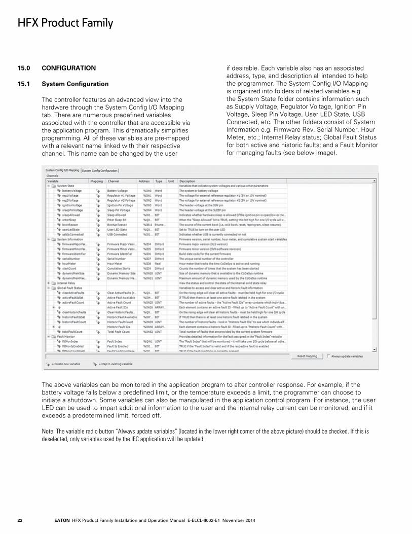
15.1 System Configuration
The controller features an advanced view into the hardware through the System Config I/O Mapping tab. There are numerous predefined variables associated with the controller that are accessible via the application program. This dramatically simplifies programming. All of these variables are pre-mapped with a relevant name linked with their respective channel. This name can be changed by the user
if desirable. Each variable also has an associated address, type, and description all intended to help the programmer. The System Config I/O Mapping is organized into folders of related variables e.g. the System State folder contains information such as Supply Voltage, Regulator Voltage, Ignition Pin Voltage, Sleep Pin Voltage, User LED State, USB Connected, etc. The other folders consist of System Information e.g. Firmware Rev, Serial Number, Hour Meter, etc.; Internal Relay status; Global Fault Status for both active and historic faults; and a Fault Monitor for managing faults (see below image).
The above variables can be monitored in the application program to alter controller response. For example, if the battery voltage falls below a predefined limit, or the temperature exceeds a limit, the programmer can choose to initiate a shutdown. Some variables can also be manipulated in the application control program. For instance, the user LED can be used to impart additional information to the user and the internal relay current can be monitored, and if it exceeds a predetermined limit, forced off.
Note: The variable radio button “Always update variables” (located in the lower right corner of the above picture) should be checked. If this is deselected, only variables used by the IEC application will be updated.
EATON HFX Product Family Installation and Operation Manual E-ELCL-II002-E1 November 2014 23
HFX Product Family
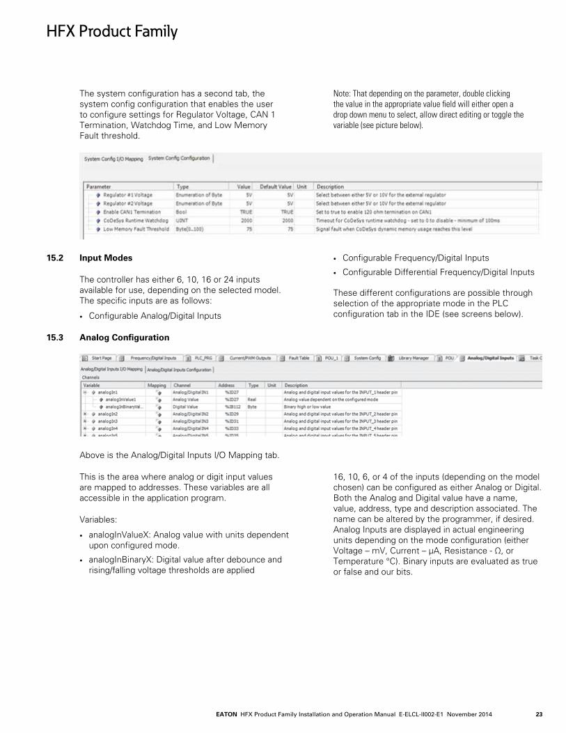
The system configuration has a second tab, the system config configuration that enables the user to configure settings for Regulator Voltage, CAN 1 Termination, Watchdog Time, and Low Memory Fault threshold.
Note: That depending on the parameter, double clicking the value in the appropriate value field will either open a drop down menu to select, allow direct editing or toggle the variable (see picture below).
15.2 Input Modes
The controller has either 6, 10, 16 or 24 inputs available for use, depending on the selected model.The specific inputs are as follows:
• Configurable Analog/Digital Inputs
• Configurable Frequency/Digital Inputs
• Configurable Differential Frequency/Digital Inputs
These different configurations are possible through selection of the appropriate mode in the PLC configuration tab in the IDE (see screens below).
15.3 Analog Configuration
Above is the Analog/Digital Inputs I/O Mapping tab.
This is the area where analog or digit input values are mapped to addresses. These variables are all accessible in the application program.
Variables:
• analogInValueX: Analog value with units dependent upon configured mode.
• analogInBinaryX: Digital value after debounce and rising/falling voltage thresholds are applied
16, 10, 6, or 4 of the inputs (depending on the model chosen) can be configured as either Analog or Digital.Both the Analog and Digital value have a name, value, address, type and description associated. The name can be altered by the programmer, if desired. Analog Inputs are displayed in actual engineering units depending on the mode configuration (either Voltage – mV, Current – μA, Resistance - Ω, or Temperature °C). Binary inputs are evaluated as true or false and our bits.
EATON HFX Product Family Installation and Operation Manual E-ELCL-II002-E1 November 201424
HFX Product Family
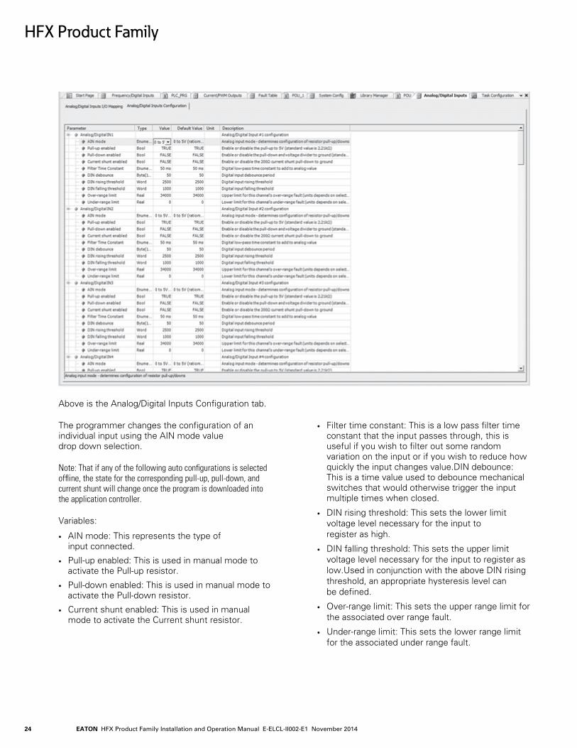
Above is the Analog/Digital Inputs Configuration tab.
The programmer changes the configuration of an individual input using the AIN mode value drop down selection.
Note: That if any of the following auto configurations is selected offline, the state for the corresponding pull-up, pull-down, and current shunt will change once the program is downloaded into the application controller.
Variables:
• AIN mode: This represents the type of input connected.
• Pull-up enabled: This is used in manual mode to activate the Pull-up resistor.
• Pull-down enabled: This is used in manual mode to activate the Pull-down resistor.
• Current shunt enabled: This is used in manual mode to activate the Current shunt resistor.
• Filter time constant: This is a low pass filter time constant that the input passes through, this is useful if you wish to filter out some random variation on the input or if you wish to reduce how quickly the input changes value.DIN debounce: This is a time value used to debounce mechanical switches that would otherwise trigger the input multiple times when closed.
• DIN rising threshold: This sets the lower limit voltage level necessary for the input to register as high.
• DIN falling threshold: This sets the upper limit voltage level necessary for the input to register as low.Used in conjunction with the above DIN rising threshold, an appropriate hysteresis level can be defined.
• Over-range limit: This sets the upper range limit for the associated over range fault.
• Under-range limit: This sets the lower range limit for the associated under range fault.

EATON HFX Product Family Installation and Operation Manual E-ELCL-II002-E1 November 2014 25
HFX Product Family
16.0 ANALOG INPUT CIRCUIT (PASSIVE REPRESENTATION)
The options are as follows:
Manual Config mode:
• Pull-up configurable
• Pull-down configurable
• Shunt configurable
Note: The manual mode is useful when connecting binary sensors. If you have a sensor that is switching ground to the input, you should enable the pull-up and set the rising threshold appropriately for the sensor (normally 2500 mV). If you have a sensor that is switching battery voltage, you should enable the pull-down and set the falling threshold appropriately for the sensor (normally less than half the battery voltage). Make sure to take into consideration the effect of hysteresis i.e. have some margin between rising and falling thresholds.
0-5 V mode (ratiometric):
• Pull-down forced off
• Pull-up configurable
• Shunt configurable
0-5 V mode (absolute):
• Pull-down forced off
• Pull-up configurable
• Shunt configurable
0-10 V and 0-34 V mode:
• Pull-down forced on
• Pull-up configurable
• Shunt configurable
0-22 mA mode:
• Pull-up forced off
• Pull-down forced off
• Shunt forced on
Thermistor raw mode (output the 10 kΩ to 50 kΩ value):
• Pull-up forced on
• Pull-down forced off
• Shunt forced off
Thermistor #1 & #2 mode (output the temperature value):
• Pull-up forced on
• Pull-down forced off
• Shunt forced off
The status of the Pull-up, Pull-down, and Shunt are displayed for convenience. In Manual Config, the programmer has complete control to alter these values.
Each of the analog modes offers a user adjustable filter.The purpose of this is to smooth an input signal and/or limit how quickly it is changing. The filter is a digital approximation of a first order series RC network (low pass filter). The adjustable time constant is equivalent to the product of R*C in a conventional RC filter. The input should follow the following curve approximately (+/- 10%): 63% of the new step-response value after 1 time constant - after 2 time constants you will get to 86% and after 3 you will get 98%.
The digital mode features adjustable rising and falling threshold levels. This is intended to offer additional flexibility in input device selection. There is also a debounce associated with each input. It is only intended for digital use (mainly to prevent inadvertent input triggering from multiple mechanical contact closures). The debounce has a user configurable time period. Each digital input can function with either Low Side or High Side input types.
Additionally, each of the modes offer a user configurable under-range and over-range limit coupled to respective fault bits.
Note 1: There is an overcurrent fault that triggers when the input exceeds approximately 23.5 mA for 25 ms in 0 – 22 mA mode.
Note 2: Ratiometric mode compensates for the measured regulated output voltage variance and normalizes the input value relative to 5 volts.

EATON HFX Product Family Installation and Operation Manual E-ELCL-II002-E1 November 201426
HFX Product Family
Note: Thermistor #1 & #2 modes display value based on two user configurable lookup tables, see below:
EATON HFX Product Family Installation and Operation Manual E-ELCL-II002-E1 November 2014 27
16.1 Thermistor
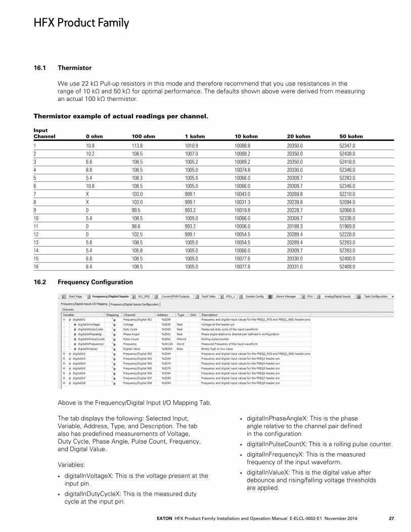
We use 22 kΩ Pull-up resistors in this mode and therefore recommend that you use resistances in the range of 10 kΩ and 50 kΩ for optimal performance. The defaults shown above were derived from measuring an actual 100 kΩ thermistor.
Thermistor example of actual readings per channel. Input Channel 0 ohm 100 ohm 1 kohm 10 kohm 20 kohm 50 kohm
1 10.8 113.8 1010.9 10088.8 20350.0 52347.02 10.2 108.5 1007.0 10089.2 20350.0 52438.03 6.8 108.5 1005.2 10089.2 20350.0 52418.04 8.8 108.5 1005.0 10074.8 20330.0 52346.05 5.4 108.3 1005.0 10066.0 20309.7 52283.06 10.8 108.5 1005.0 10066.0 20309.7 52346.07 X 103.0 999.1 10043.0 20269.8 52210.08 X 103.0 999.1 10031.3 20239.8 52094.09 0 99.5 993.2 10019.8 20228.7 52068.010 5.4 108.5 1005.0 10066.0 20309.7 52336.011 0 98.6 993.2 10006.0 20188.3 51969.012 0 102.5 999.1 10054.5 20289.4 52220.013 5.8 108.5 1005.0 10054.5 20289.4 52283.014 5.4 105.8 1005.0 10066.0 20309.7 52283.015 6.8 108.5 1005.0 10077.6 20330.0 52400.016 6.4 108.5 1005.0 10077.8 20331.0 52408.0
16.2 Frequency Configuration
Above is the Frequency/Digital Input I/O Mapping Tab.
The tab displays the following: Selected Input, Variable, Address, Type, and Description. The tab also has predefined measurements of Voltage, Duty Cycle, Phase Angle, Pulse Count, Frequency, and Digital Value.
Variables:
• digitalInVoltageX: This is the voltage present at the input pin.
• digitalInDutyCycleX: This is the measured duty cycle at the input pin.
• digitalInPhaseAngleX: This is the phase angle relative to the channel pair defined in the configuration
• digitalInPulseCountX: This is a rolling pulse counter.
• digitalInFrequencyX: This is the measured frequency of the input waveform.
• digitalInValueX: This is the digital value after debounce and rising/falling voltage thresholds are applied.
HFX Product Family

EATON HFX Product Family Installation and Operation Manual E-ELCL-II002-E1 November 201428
Above is the Frequency/Digital Input Configuration tab.
This tab allows the user to configure any of the frequency input tabs.
Variables:
• Termination mode: This is where the combination of pull-up and pull-down resistors is configured.
• DIN debounce: This is the time value used to debounce mechanical switches that would otherwise trigger the input multiple times when closed.
• DIN rising threshold: This is the rising threshold voltage for digital inputs (effects the digital value only).
• DIN falling threshold: This is the falling threshold voltage for digital inputs(effects the digital value only).
• Phase channel pair: This selects channel pair used for phase comparison (1 is 1st pair, 2nd is 2nd pair, etc.).
• Filter time constant: This is a low pass filter time constant that is used on the following values: frequency, duty cycle, and voltage measurements.
• Over-voltage limit: This is the upper limit used for the over-voltage fault.
• Lower-voltage limit: This is the lower voltage limit used for the under-voltage fault.
• Frequency rising edge threshold: This enables either the adaptive (peak-detect) rising edge voltage threshold or the fixed 2.2 V threshold for the frequency circuit.
• Frequency falling edge threshold: This enables either 1.0 V or 0 V as the falling edge voltage threshold for the requency circuit.
This tab enables the programmer to change the configuration of an individual input using the termination mode value drop down selection. The options are as follows:
HFX Product Family

EATON HFX Product Family Installation and Operation Manual E-ELCL-II002-E1 November 2014 29
17.0 FREQUENCY INPUT CIRCUIT (PASSIVE REPRESENTATION)
Open Circuit mode:
• Pull to VLoad
• Pull to 5 V
• Pull to Ground
• Pull to 5 V & Ground
The digital input mode functions as it does with the Analog/Digital Input Configuration. It features the same set of parameters for configuring debounce, rising threshold level, and falling threshold. These inputs also support both Low-Side and High-Side input types. Although it is dependent on the specific sensor, normally in the case of a high side input (input is connected to ground), the Pull to VLoad should be selected. In this case it is important to make sure the sensor is rated for the full load voltage. Normally in the case of a low side input (input is connected to Battery +), the Pull to Ground option should be selected.
There are 8, 6, 4, or 2 inputs that can be configured as Frequency depending on the model selected. Inputs 1 and 2 have the additional capability to handle differential signals i.e. VR inputs on all models. When measuring phase, do not mix Inputs 1 and 2 with any of the other frequency inputs. The differential inputs also work with single ended sensors. In order to use these, just ground the input on the differential pair.
Note that the VR input can be configured with preset rising (2.2 V) and falling (0 or 1 V) thresholds for the measurement of our proprietary adaptive algorithm which compensates for large increases in peak level that are common with these types of sensors. Due to the nature of the circuit design used in the differential frequency inputs, duty cycle calculation is not supported on these two channels. Additionally, note that the accuracy of phase measurement is more limited than with the other 6 channels. Also, when measuring frequency, phase, pulse width, or count, the measurement limit is the shortest detectable pulse i.e. 20 μS. When using inputs configured as Frequency, voltage indication is not supported. Also note that the debounce filters are not intended for frequency inputs in general. When using channels 3 – 8 as frequency input, these are single ended inputs and trigger on 3 volt rising and 2 volt falling.
Note: That there is a fault that trips if the combined input frequency of all channels exceeds 200 kHz. This does not stop operation, but is intended as a warning that you are exceeding the limits of what the hardware can measure.
Note: When any of the above channels are configured as digital (HS or LS) the sampling frequency is 200 Hz. The debounce filters are intended for this mode.
17.1 Output Modes
The controller has either 6, 10, 16, or 24 outputs available for use. The outputs are all configurable as High Side Digital (ON/OFF), PWM open loop voltage, PWM(i) closed loop current control. In addition to these options a group of outputs support Low Side Digital Output (ON/OFF), PWM
1. High Side Switch (HS): This mode of operation is the standard output to turn a load on or off. The individual outputs can switch up to either 2 or 4 A loads depending on the output selected. This mode also supports PWM to drive a load propor-tionally.
2. Binary: This mode is intended for strictly on/off switching of a load.
HFX Product Family

EATON HFX Product Family Installation and Operation Manual E-ELCL-II002-E1 November 201430
Above is the Current/PWM Outputs I/O Mapping tab.
This tab displays the desired current, actual current, desired PWM duty cycle, actual PWM duty cycle, and the binary output status.
Variables:
• desiredCurrentX_XA: This is the desired output current for the channel. Note: That this is only active in Current Control mode.
• measuredCurrentX_XA: This is the average current measured over a single dither period.
• desiredDutyX_XA: This is the desired PWM duty cycle. Note: That this is only active in PWM mode.
• actualDutyX_XA: This is the PWM duty cycle commanded by the hardware.
• binaryOutputX_XA: This is the commanded output state of the high or low side output (false: open or True: closed). Note: That this is only active in Binary mode.
HFX Product Family

EATON HFX Product Family Installation and Operation Manual E-ELCL-II002-E1 November 2014 31
Above is the Current/PWM Outputs Configuration tab.
This tab displays indications that reflect faults associated with the outputs (i.e. short to Vbat, short to ground, open circuit, over current, and loss of control). Additionally, the individual channels PWM Frequency, Dither Frequency, Dither Amplitude, Drive Mode, Fault processing, Proportional, and Integral gain can all be configured here.
Variables:
• PWM Frequency: This is the fundamental frequency used to drive the output driver (note) that this must be ≥ Dither Frequency. The 2 A outputs support a maximum of 2 kHz & the 4 A outputs support a maximum of 500 Hz.
• Dither Frequency: This is the frequency that modulates the PWM duty cycle signal (note) that this must be ≤ PWM Frequency.
• Dither Amplitude: This is the amount of peak to peak variation in % of PWM duty cycle used for dithering.
• Drive Mode: This selects between closed loop current control mode or open loop PWM duty cycle mode.
• High or Low Side: Selects between a high or low side driver for the channel (note that this only applies to 4 A channels).
• Enable Channel Faults: Select to enable automatic system fault processing for this output channel.
• K_p: Proportional gain for current control loop.
• K_i: Integral gain for current control loop.
Shared Variables:
• DUTY_HS: High Side PWM duty cycle commanded < High Side PWM measured indicates a short to battery fault.
• DUTY_LS: Low Side PWM duty cycle commanded > Low Side PWM measured indicates a potential short to battery fault.
• VLOAD_RATIO: Measured output voltage > commanded output voltage indicates a potential short to battery fault.
• OPEN_DUTY: Commanded duty cycle > measured duty cycle indicates a potential open load condition.
HFX Product Family
EATON HFX Product Family Installation and Operation Manual E-ELCL-II002-E1 November 201432
• OPEN_CURRENT: Commanded current > measured current indicates a potential open load condition.
• GND_SHRT_DUTY: Measured low side duty cycle < commanded indicates a potential short to ground condition.
• GND_SHRT_VRATIO: Measured voltage < commanded voltage indicates a potential short to ground condition.
• MAX_CURRENT: The value selected here sets a software limit for monitoring individual High Side output current. If the measured current exceeds either the hardware limit or the value defined here, it will cause the Over Current fault.
• OFF_CURRENT: If Duty Cycle = 0% and measured current > OFF_CURRENT value defined here or the measured reverse current > 75 mA the Loss of Control fault will be triggered.
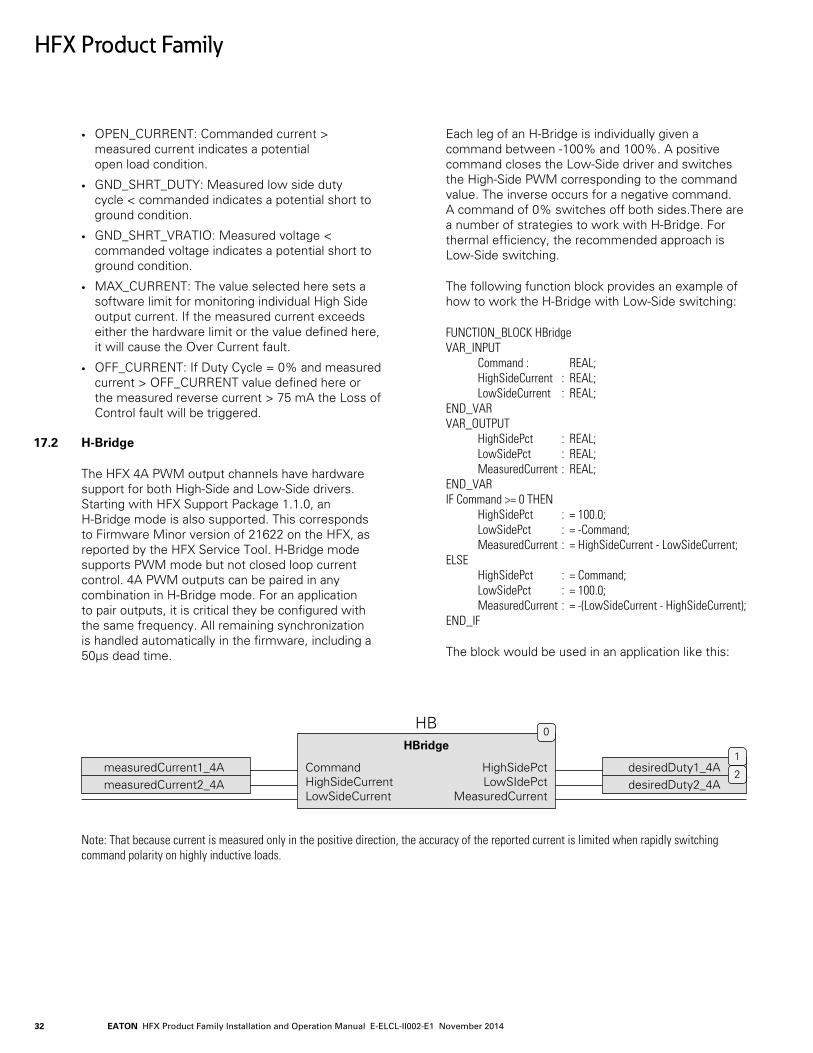
17.2 H-Bridge
The HFX 4A PWM output channels have hardware support for both High-Side and Low-Side drivers. Starting with HFX Support Package 1.1.0, an H-Bridge mode is also supported. This corresponds to Firmware Minor version of 21622 on the HFX, as reported by the HFX Service Tool. H-Bridge mode supports PWM mode but not closed loop current control. 4A PWM outputs can be paired in any combination in H-Bridge mode. For an application to pair outputs, it is critical they be configured with the same frequency. All remaining synchronization is handled automatically in the firmware, including a 50µs dead time.
Each leg of an H-Bridge is individually given a command between -100% and 100%. A positive command closes the Low-Side driver and switches the High-Side PWM corresponding to the command value. The inverse occurs for a negative command. A command of 0% switches off both sides.There are a number of strategies to work with H-Bridge. For thermal efficiency, the recommended approach is Low-Side switching.
The following function block provides an example of how to work the H-Bridge with Low-Side switching:
FUNCTION_BLOCK HBridge VAR_INPUT Command : REAL; HighSideCurrent : REAL; LowSideCurrent : REAL; END_VAR VAR_OUTPUT HighSidePct : REAL; LowSidePct : REAL; MeasuredCurrent : REAL; END_VAR IF Command >= 0 THEN HighSidePct : = 100.0; LowSidePct : = -Command; MeasuredCurrent : = HighSideCurrent - LowSideCurrent; ELSE HighSidePct : = Command; LowSidePct : = 100.0; MeasuredCurrent : = -(LowSideCurrent - HighSideCurrent); END_IF
The block would be used in an application like this:
HBridge
HB
CommandHighSideCurrentLowSideCurrent
HighSidePctLowSIdePct
MeasuredCurrent
0
desiredDuty1_4AdesiredDuty2_4A
1
2measuredCurrent1_4AmeasuredCurrent2_4A
Note: That because current is measured only in the positive direction, the accuracy of the reported current is limited when rapidly switching command polarity on highly inductive loads.
HFX Product Family
EATON HFX Product Family Installation and Operation Manual E-ELCL-II002-E1 November 2014 33
18.0 OUTPUT CIRCUIT (PASSIVE REPRESENTATION)
18.1 Overcurrent Shutdown
The individual outputs of the unit are fully protected and will switch off if overloaded. When diagnostics are enabled and an overcurrent event occurs, the output will switch and remain off until another off/on command is received. The overcurrent shutdown is dependent upon the specific output. 2 A rated outputs have a slow blow level of approximately 2.1 A and a fast blow level of approximately 2.4 A. 4 A rated outputs have a slow blow level of approximately 4.1 A and a fast blow level of approximately 4.4 A. All outputs are additionally protected via an internal solid state relay. The relay can be active monitored for current and controlled in the user program.
19.0 PWM
19.1 What is PWM?
PWM stands for Pulse Width Modulation. It is a method that can be used to efficiently drive solenoid valves. Typically the output device is switched at a fast rate (60 Hz – 2 kHz).
In the past solenoid valves were driven using a transistor or op amp in linear mode. This worked well to control the valve as a directly proportional voltage signal could be easily controlled using feedback. The negative of this technique is that it generates a great deal of heat, is inefficient, and requires a larger enclosures since the output device is operated in between cutoff and saturation and is behaving like a variable resistor constantly having to dissipate the power not used by the load as heat.
PWM uses the output device digitally and therefore the device is either on or off. Using this technique the output device supplies a series of pulses of the same voltage level to the load. Since transistors are very efficient when either on or off, much less heat is dissipated. By varying the duty cycle (on time/switching period) the output effectively can emulate an analog signal, especially at the higher switching frequencies through a solenoid valve coils inductance.
Current feedback can be used to more effectively control the valve. With a known current flowing through the valve coil, the valve spool position can be precisely determined. The added advantage of this method is that it is independent of temperature.
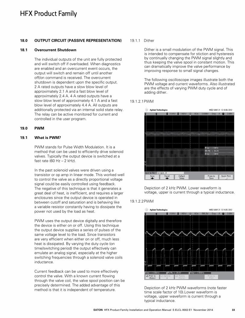
19.1.1 Dither
Dither is a small modulation of the PWM signal. This is intended to compensate for stiction and hysteresis by continually changing the PWM signal slightly and thus keeping the valve spool in constant motion. This can dramatically improve the valve performance by improving response to small signal changes.
The following oscilloscope images illustrate both the PWM voltage and current waveforms. Also illustrated are the effects of varying PWM duty cycle and of adding dither.
19.1.2.1 PWM
Depiction of 2 kHz PWM. Lower waveform is voltage, upper is current through a typical inductance.
19.1.2.2 PWM
Depiction of 2 kHz PWM waveforms (note faster time scale factor of 10).Lower waveform is voltage, upper waveform is current through a typical inductance.
HFX Product Family

EATON HFX Product Family Installation and Operation Manual E-ELCL-II002-E1 November 201434
19.1.3.1 PWM with Dither
Depiction of 2 kHz PWM with 100 Hz 40% dither. Lower waveform is voltage, upper waveform is current through a typical inductance.
19.1.3.2 PWM with Dither
Single cycle of 2 kHz PWM with 100 Hz 40% dither.
Note: PWM voltage duty cycle is changing value +/- 20% from commanded value at a rate of 100 Hz.
19.1.3.3 PWM with Dither
PWM with dither illustrating duty cycle 62% (42% + 20%)
19.1.3.4 PWM with Dither
PWM with dither illustrating duty cycle 22% (42% - 20%)
HFX Product Family

EATON HFX Product Family Installation and Operation Manual E-ELCL-II002-E1 November 2014 35
20.0 CAN & SAE J1939
• Each device added to the J1939 manager represents a physical device on the bus.• So a "local device" represents the local mobile controller. This is
the message the controller will be *transmitting*.See the "local device" checkbox in the general tab.
• A non-"local device" represents a physical device on the bus. Thus its "Tx Signals" are what the device is sending and the mobile controller is receiving.
• Thus you should generally add one "device" to the tree to represent each device that is on the physical bus, including the "local" device.
• Also make sure you have the "local device" checked for the node that you want to use to transmit signals. While this is not intuitive at first, it makes complete sense once you are aware of it.
• There are no function blocks and everything happens automatically in the background. You just get scaled variables you can read or write from code.
• All transmission happens automatically per the configuration for each PGN. The "TransmissionMode" tab specifies the interval. Relevant options are "Change of State" and "Cyclic", but the default is change of state so the packet will not be sent unless one of the variables changes (i.e. from your code). Cyclic is the more traditional J1939 method and better for testing.The "I/O" mapping tab represents all the variables available in the device. These can be used in code for either inputs or outputs depending on whether it is a transmitted or received packet.
• You can automatically convert and scale variables by clicking on the SPN in the "Tx Signals" page, and then enabling the "Conversion" option. This lets you deal in engineering units (i.e. %, rpm, mph, etc) as opposed to the raw data bytes.
• Variables in the I/O mapping tab will not be updated unless physically used in code. This is an optimization done by the 3S compiler to reduce computation for unused variables. For debugging, you can check the "Always update variables" box and it will instruct the compiler/debugger to always display and update the values.
• The CAN "Network" option is base-zero. Thus Network 0 represents the first CAN bus, Network 1 represents the second CAN bus, and Network 2 represents the third.
21.0 INPUT STATUS, FEEDBACK, AND DIAGNOSTICS
A fault table is integrated in the IDE. Please see the below samples. When a fault occurs, an exclamation will come on the “Fault Table” icon indicating “Diagnostic message available”. If there is an active fault that relates to a PWM, analog, or frequency channel, then the respective icon will also display the red triangle as well. One message is displayed at a time in the “Fault Table Status” tab. When Acknowledge is selected the current fault is cleared and the next fault is displayed. If the fault cannot be cleared, it will remain until the condition is fixed.
HFX Product Family
EATON HFX Product Family Installation and Operation Manual E-ELCL-II002-E1 November 201436
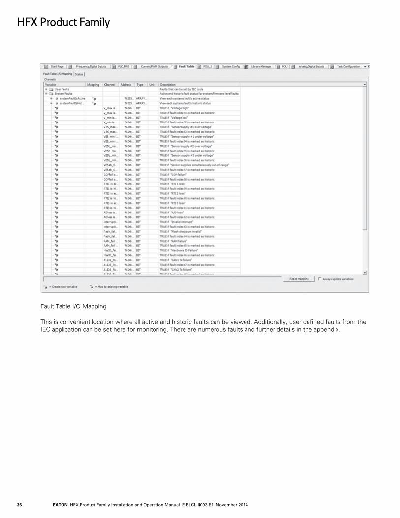
Fault Table I/O Mapping
This is convenient location where all active and historic faults can be viewed. Additionally, user defined faults from the IEC application can be set here for monitoring. There are numerous faults and further details in the appendix.
HFX Product Family

EATON HFX Product Family Installation and Operation Manual E-ELCL-II002-E1 November 2014 37
21.1 Block Diagram
HFX Product Family
HFX12m
Output Power
I/O System (6 Inputs/6 Outputs)
Controller Power
Prog
ram
min
gIn
terf
ace
CAN
Bus
(J19
39/C
AN
open
)A
nalo
g/D
igita
l In
puts
(0..5
V, 0
..10V
, 0..3
4V,
0..2
2mA
, The
rmis
tor,
Dig
ital H
igh/
Low
Sid
e, V
aria
ble
Relu
ctan
ce*)
Freq
uenc
y/D
igita
l In
puts
(Dig
ital H
igh/
Low
Sid
e,
Vari
able
Rel
ucta
nce*
)
PWM
/Dig
ital
Out
puts
- 2A
(Cur
rent
Fe
edba
ck, D
igita
l Hig
h Si
de)
PWM
/Dig
ital
Out
puts
- 4A
(Cur
rent
Fe
edba
ck, D
igita
l Hig
h/Lo
w S
ide)
Sens
or P
ower
Supp
ly 1
*Note: Only FREQ1 & FREQ2 support variable reluctance type sensors inputs
SENS_PWR+ 30ASENS_PWR- 20A
22A CAN1_H12A CAN1_L
4P CAN1_H5P CAN1_L
13A CAN2_H23A CAN2_L
14A CAN3_H24A CAN3_L
1P USB_GND2P USB_D-3P USB_D+6P USB_+5V
21A INPUT_111A INPUT_233A INPUT_334A INPUT_4
36A FREQ1_POS37A FREQ1_NEG38A FREQ2_POS39A FREQ2_NEG
26A Sleep16A IGN
6A VBATT+
PWM1_4A 1APWM2_4A 35A
10A Load_PWR+19A Load_PWR+
9A Load_PWR+Load_PWR- 28ALoad_PWR- 29A
Load_PWR- 18A
VBATT- 7A
PWM1_2A 2APWM2_2A 3APWM3_2A 4APWM4_2A 5A
EATON HFX Product Family Installation and Operation Manual E-ELCL-II002-E1 November 201438
HFX Product Family
HFX20m
Output Power
I/O System (10 Inputs/10 Outputs)
Controller Power
Prog
ram
min
gIn
terf
ace
CAN
Bus
(J19
39/C
AN
open
)A
nalo
g/D
igita
l In
puts
(0..5
V, 0
..10V
, 0..3
4V,
0..2
2mA
, The
rmis
tor,
Dig
ital H
igh/
Low
Sid
e, V
aria
ble
Relu
ctan
ce*)
Freq
uenc
y/D
igita
l In
puts
(Dig
ital H
igh/
Low
Sid
e,
Vari
able
Rel
ucta
nce*
)
PWM
/Dig
ital
Out
puts
- 2A
(Cur
rent
Fe
edba
ck, D
igita
l Hig
h Si
de)
PWM
/Dig
ital
Out
puts
- 4A
(Cur
rent
Fe
edba
ck, D
igita
l Hig
h/Lo
w S
ide)
Sens
or P
ower
Supp
ly 1
*Note: Only FREQ1 & FREQ2 support variable reluctance type sensors inputs
SENS_PWR+ 30ASENS_PWR- 20A
22A CAN1_H12A CAN1_L
4P CAN1_H5P CAN1_L
13A CAN2_H23A CAN2_L
14A CAN3_H24A CAN3_L
1P USB_GND2P USB_D-3P USB_D+6P USB_+5V
26A Sleep16A IGN
6A VBATT+
PWM1_4A 1APWM2_4A 35APWM3_4A 31APWM4_4A 8A
10A Load_PWR+19A Load_PWR+
9A Load_PWR+Load_PWR- 28ALoad_PWR- 29A
Load_PWR- 18A
VBATT- 7A
PWM1_2A 2APWM2_2A 3APWM3_2A 4APWM4_2A 5APWM5_2A 40APWM6_2A 32A
21A INPUT_111A INPUT_233A INPUT_334A INPUT_425A INPUT_515A INPUT_5
36A FREQ1_POS37A FREQ1_NEG38A FREQ2_POS39A FREQ2_NEG17A FREQ327A FREQ4
EATON HFX Product Family Installation and Operation Manual E-ELCL-II002-E1 November 2014 39
HFX Product Family
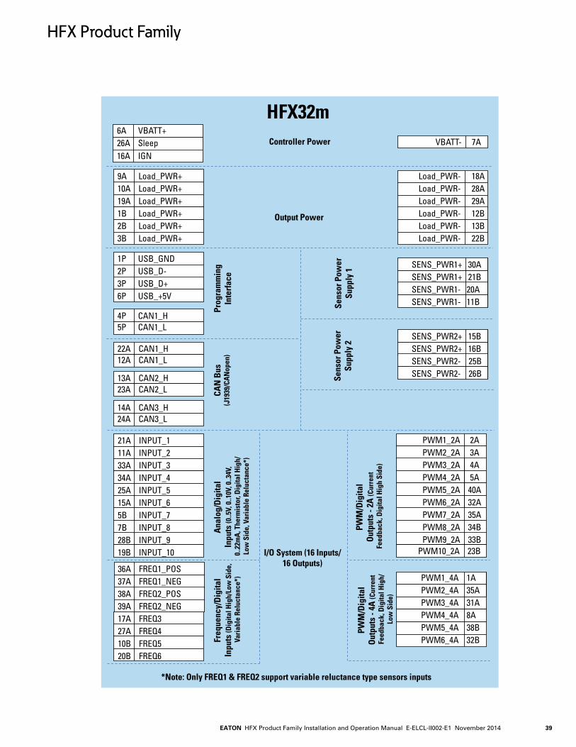
HFX32m
Output Power
I/O System (16 Inputs/16 Outputs)
Controller Power
Prog
ram
min
gIn
terf
ace
CAN
Bus
(J19
39/C
AN
open
)A
nalo
g/D
igita
l In
puts
(0..5
V, 0
..10V
, 0..3
4V,
0..2
2mA
, The
rmis
tor,
Dig
ital H
igh/
Low
Sid
e, V
aria
ble
Relu
ctan
ce*)
Freq
uenc
y/D
igita
l In
puts
(Dig
ital H
igh/
Low
Sid
e,
Vari
able
Rel
ucta
nce*
)
PWM
/Dig
ital
Out
puts
- 2A
(Cur
rent
Fe
edba
ck, D
igita
l Hig
h Si
de)
PWM
/Dig
ital
Out
puts
- 4A
(Cur
rent
Fe
edba
ck, D
igita
l Hig
h/Lo
w S
ide)
Sens
or P
ower
Supp
ly 1
Sens
or P
ower
Supp
ly 2
*Note: Only FREQ1 & FREQ2 support variable reluctance type sensors inputs
22A CAN1_H12A CAN1_L
4P CAN1_H5P CAN1_L
13A CAN2_H23A CAN2_L
14A CAN3_H24A CAN3_L
1P USB_GND2P USB_D-3P USB_D+6P USB_+5V
26A Sleep16A IGN
6A VBATT+
PWM1_4A 1APWM2_4A 35APWM3_4A 31APWM4_4A 8APWM5_4A 38BPWM6_4A 32B
VBATT- 7A
9A Load_PWR+10A Load_PWR+19A Load_PWR+1B Load_PWR+2B Load_PWR+3B Load_PWR+
Load_PWR- 18A Load_PWR- 28ALoad_PWR- 29ALoad_PWR- 12BLoad_PWR- 13BLoad_PWR- 22B
SENS_PWR1+ 30ASENS_PWR1+ 21BSENS_PWR1- 20ASENS_PWR1- 11B
SENS_PWR2+ 15BSENS_PWR2+ 16BSENS_PWR2- 25BSENS_PWR2- 26B
21A INPUT_111A INPUT_233A INPUT_334A INPUT_425A INPUT_515A INPUT_65B INPUT_77B INPUT_828B INPUT_919B INPUT_10
36A FREQ1_POS37A FREQ1_NEG38A FREQ2_POS39A FREQ2_NEG17A FREQ327A FREQ410B FREQ520B FREQ6
PWM1_2A 2APWM2_2A 3APWM3_2A 4APWM4_2A 5APWM5_2A 40APWM6_2A 32APWM7_2A 35APWM8_2A 34BPWM9_2A 33B
PWM10_2A 23B

EATON HFX Product Family Installation and Operation Manual E-ELCL-II002-E1 November 201440
HFX Product Family
HFX48m
Output Power
I/O System (24 Inputs/24 Outputs)
Controller Power
Prog
ram
min
gIn
terf
ace
CAN
Bus
(J19
39/C
AN
open
)A
nalo
g/D
igita
l In
puts
(0..5
V, 0
..10V
, 0..3
4V,
0..2
2mA
, The
rmis
tor,
Dig
ital H
igh/
Low
Sid
e, V
aria
ble
Relu
ctan
ce*)
Freq
uenc
y/D
igita
l In
puts
(Dig
ital H
igh/
Low
Sid
e Va
riab
le R
eluc
tanc
e*)
PWM
/Dig
ital
Out
puts
- 2A
(Cur
rent
Fe
edba
ck, D
igita
l Hig
h Si
de)
PWM
/Dig
ital
Out
puts
- 4A
(Cur
rent
Fe
edba
ck, D
igita
l Hig
h/Lo
w S
ide)
Sens
or P
ower
Supp
ly 1
Sens
or P
ower
Supp
ly 2
*Note: Only FREQ1 & FREQ2 support variable reluctance type sensors inputs
22A CAN1_H12A CAN1_L
4P CAN1_H5P CAN1_L
13A CAN2_H23A CAN2_L
14A CAN3_H24A CAN3_L
1P USB_GND2P USB_D-3P USB_D+6P USB_+5V
26A Sleep16A IGN
6A VBATT+
PWM1_4A 1APWM2_4A 35APWM3_4A 31APWM4_4A 8APWM5_4A 38BPWM6_4A 32BPWM7_4A 6BPWM8_4A 4B
VBATT- 7A
9A Load_PWR+10A Load_PWR+19A Load_PWR+1B Load_PWR+2B Load_PWR+3B Load_PWR+
Load_PWR- 18A Load_PWR- 28ALoad_PWR- 29ALoad_PWR- 12BLoad_PWR- 13BLoad_PWR- 22B
SENS_PWR1+ 30ASENS_PWR1+ 21BSENS_PWR1- 20ASENS_PWR1- 11B
SENS_PWR2+ 15BSENS_PWR2+ 16BSENS_PWR2- 25BSENS_PWR2- 26B
36A FREQ1_POS37A FREQ1_NEG38A FREQ2_POS39A FREQ2_NEG17A FREQ327A FREQ410B FREQ520B FREQ629B FREQ730B FREQ8
PWM1_2A 2APWM2_2A 3APWM3_2A 4APWM4_2A 5APWM5_2A 40APWM6_2A 32APWM7_2A 35APWM8_2A 34BPWM9_2A 33BPWM10_2A 23BPWM11_2A 39BPWM12_2A 31BPWM13_2A 24BPWM14_2A 36BPWM15_2A 37BPWM16_2A 40B
21A INPUT_111A INPUT_233A INPUT_334A INPUT_425A INPUT_515A INPUT_65B INPUT_77B INPUT_828B INPUT_919B INPUT_1018B INPUT_1114B INPUT_1217B INPUT_1327B INPUT_149B INPUT_158B INPUT_16
EATON HFX Product Family Installation and Operation Manual E-ELCL-II002-E1 November 2014 41
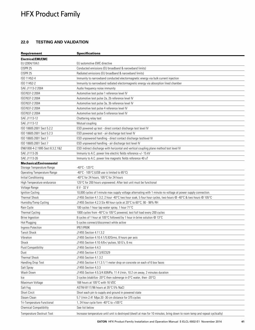
22.0 TESTING AND VALIDATION
Requirement Specifications
Electrical/EMI/EMC EU (2004/104/) EU automotive EMC directiveCISPR 25 Conducted emissions (EU broadband & narowband limits)CISPR 25 Radiated emissions (EU broadband & narowband limits)ISO 11452-4 Immunity to narrowband conducted electormagnetic energy via bulk current injectionISO 11452-2 Immunity to narrowband radiated electormagnetic energy via absorption lined chamberSAE J1113-2:2004 Audio frequency noise immunityISO7637-2:2004 Automotive test pulse 1 reference level IVISO7637-2:2004 Automotive test pulse 2a, 2b reference level IVISO7637-2:2004 Automotive test pulse 3a, 3b reference level IVISO7637-2:2004 Automotive test pulse 4 reference level IVISO7637-2:2004 Automotive test pulse 5 reference level IVSAE J1113-12 Chattering relay testSAE J1113-12 Mutual couplingISO 10605:2001 Sect 5.2.2 ESD powered up test - direct contact discharge test level IVISO 10605:2001 Sect 5.2.3 ESD powered up test - air discharge test level IVISO 10605:2001 Sect 7 ESD unpowered handling - direct contact discharge testlevel IVISO 10605:2001 Sect 7 ESD unpowered handling - air discharge test level IVEN61000-4-2:1995 Sect 8.3.2.1&2 ESD indirect discharge with horizontal and vertical coupling plane method test level IVSAE J1113-26 Immuniy to A.C. power line electric fields reference +/- 15 kVSAE J1113-26 Immuniy to A.C. power line magnetic fields reference 40 uTMechanical/Environmental Storage Temperature Range -40°C - 125°COperating Temperature Range -40°C - 105°C (USB use is limited to 85°C)Initial Conditioning -40°C for 24 hours, 105°C for 24 hours High Temperature endurance 125°C for 200 hours unpowered. After test unit must be functionalVoltage Range 6 V - 32 VIgnition Cycling 10,000 cycles of I minute max supply voltage alternating with 1 minute no voltage at power supply connection. Thermal Shock J1455 Section 4.1.3.2; 2 hour -40°C two hour soak, 5 four hour cycles, two hours @ -40°C & two hours @ 105°CHumidity/Temp Cycling J1455 Section 4.2.3 Six 48 hour cycle at 20°C to 60°C, 90 - 98% RHRain Cycle 100 cycles 1 hour tap water spray, 1 hour 71°CThermal Cycling 1000 cycles from -40°C to 105°C powered, test full load every 200 cyclesBrine Ingestion 8 cycles of 1 hour at 105°C followed by 1 hour in brine solution @ 13°CHot Plugging 5 cycles connect/disconnect while activeIngress Potection IP67/IP69KTansit Shock J1455 Section 4.11.3.2Vibration J1455 Section 4.10.4.1/5.82Grms, 8 hours per axisShock J1455 Section 4.10.4/6+/-pulses, 50 G's, 6 msFluid Compatibility J1455 Section 4.4.3Dust J1455 Section 4.7.3/IEC529Thermal Shock J1455 Section 4.1.3.2Handling Drop Test J1455 Section 4.11.3.1/ 1 meter drop on concrete on each of 6 box facesSalt Spray J1455 Section 4.3.3Wash Down J1455 Section 4.5.3/4.83MPa, 11.4 l/min, 10.2 cm away, 2 minutes durationIce 3 cycles (stabilize -20°C then submerge in 0°C water, then -20°C)Maximum Voltage 168 hours at 105°C with 16 VDCSalt Fog ASTM-B117/96 hours at 35°C 5% NaClShort Circit Short each pin to supply and ground in powered stateSteam Clean 5.7 l/min 2.41 Mpa 20 -30 cm distance for 375 cyclesTri-Temperature Functional 1, 24 hour cycle form -40°C to +105°CChemical Compatibility See list below
Temperature Destruct Test Increase temperature until unit is destroyed (dwell at max for 10 minutes, bring down to room temp and repeat cyclically)
HFX Product Family

EATON HFX Product Family Installation and Operation Manual E-ELCL-II002-E1 November 201442
23.0 SERVICE TOOL
Please see page 13 for details covering firmware installation. One of the primary purposes of the Service tool is to provide an aid for troubleshooting. There are five pages that display and or allow configuration of various I/O types.
The above page is the Main page. This page allow the user to check the status of the MIL, supply voltage, ignition pin voltage, solid state relay, hours of use, and application. It also provides the total output current and several additional details about the software and hardware setup. Additionally, the output voltage on the regulated sensor supply can be adjusted.
HFX Product Family
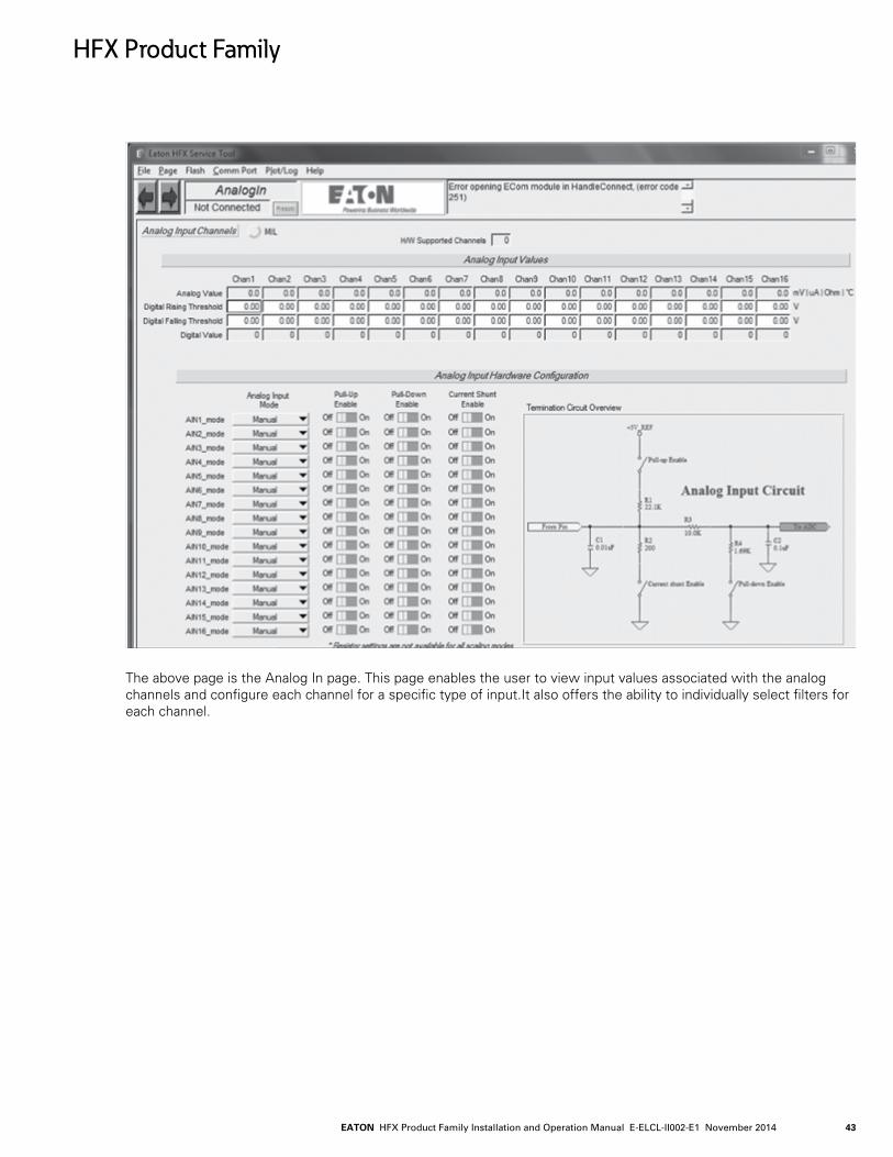
EATON HFX Product Family Installation and Operation Manual E-ELCL-II002-E1 November 2014 43
The above page is the Analog In page. This page enables the user to view input values associated with the analog channels and configure each channel for a specific type of input.It also offers the ability to individually select filters for each channel.
HFX Product Family

EATON HFX Product Family Installation and Operation Manual E-ELCL-II002-E1 November 201444
The above page is the Freq In page. This page enables the user to view input values associated with the frequency channels and configure each channel for a specific type of input.
HFX Product Family
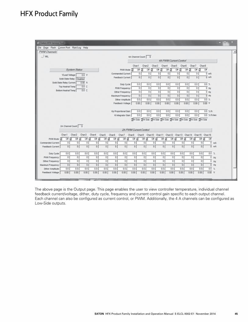
EATON HFX Product Family Installation and Operation Manual E-ELCL-II002-E1 November 2014 45
The above page is the Output page. This page enables the user to view controller temperature, individual channel feedback current/voltage, dither, duty cycle, frequency and current control gain specific to each output channel. Each channel can also be configured as current control, or PWM. Additionally, the 4 A channels can be configured as Low-Side outputs.
HFX Product Family
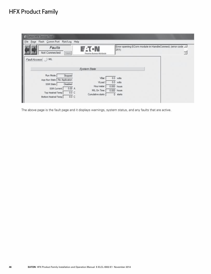
EATON HFX Product Family Installation and Operation Manual E-ELCL-II002-E1 November 201446
The above page is the fault page and it displays warnings, system status, and any faults that are active.
HFX Product Family
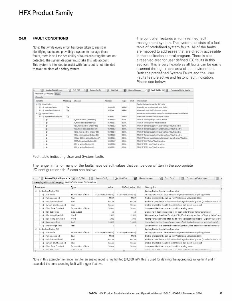
EATON HFX Product Family Installation and Operation Manual E-ELCL-II002-E1 November 2014 47
24.0 FAULT CONDITIONS
Note: That while every effort has been taken to assist in identifying faults and providing a system to manage these faults, there is still the possibility of faults occurring that are not detected. The system designer must take this into account. This system is intended to assist with faults but is not intended to take the place of a safety system.
The controller features a highly refined fault management system. The system consists of a fault table of predefined system faults. All of the faults are mapped to addresses that are directly accessible in the application control program. There is also a reserved area for user defined IEC faults in this section. This is very flexible as all faults can be easily scanned through in one area of the environment. Both the predefined System Faults and the User Faults feature active and historic fault indication. Please see below:
Fault table indicating User and System faults
The range limits for many of the faults have default values that can be overwritten in the appropriate I/O configuration tab. Please see below:
Note in this example the range limit for an analog input is highlighted (34,000 mV), this is used for defining the appropriate range limit and if exceeded the corresponding fault will trigger if active.
HFX Product Family

EATON HFX Product Family Installation and Operation Manual E-ELCL-II002-E1 November 201448
The System Configuration I/O mapping contains the following:
A set of Global fault status variables to aid in managing faults. This consists of active and historic faults, a fault count, as well as a means to clear the faults. There is also a Fault Monitor where specific faults can be monitored. See below:
Note: the location of Global Fault Status and Fault Monitor shown above.
The following are the predefined faults:
VE5_max and VE5b_max – indicates the sensor_supply_1/2 are shorted to something above 5V (i.e. 12V power).
VE5_min and VE5b_min – indicates the sensor _ supply_1/2 is shorted to ground.
VE5ab_OOR - Both sensor supplies are "out-of-range". So if you short both high or short both low it will occur. It is functionally (VE5_max OR VE5_min) AND (VE5b_max OR VE5b_min).
COPfail is active - This is the system/firmware COP (computer operating properly) fault, AKA watchdog.This will only occur if there is a bug that causes the firmware to lock up or not trigger the COP approximately every 100ms.
RTI is active – This indicates that one of the internal firmware loops is not executing (1ms/5ms/50ms). – Basically this is similar to a COP for each of our internal loops.
RTI2 is active – As above.
RTI3 is active – As above.
Adloss is active – This occurs if the ADC routine is not running for some reason (similar to a COP overseeing the ADC operation).
Interrupt is active – This is caused if an invalid/unhandled interrupt is ever executed.
flash_fail is active - CPU hardware error.
RAM_fail is active - CPU hardware error.
HWID_fail is active - 2 specific resistors are present on the PCB. There value is used to identify the PCB hardware version. If these are at an unknown value, this fault will trigger.
J1939_Tx(x)Fail is active – Currently unsupported in CODESYS.
J1939_Rx(x)Fail is active - Currently unsupported in CODESYS.
DevDesc_error is active - This indicates there is a mismatch between the firmware and CODESYS device description.xml.
Illegal_flash write is active – This is an indication that CODESYS is attempting to write to a restricted address in flash.
Cpu_addr_err is active – This fault occurs if the CPU attempts to read or write an illegal or mis-aligned address. CODESYS will trigger this fault if you don't do a clean all.
Illegal_instr is active – This is similar to cpu_addr_err; however, it is for illegal instructions encountered by the CPU
FPU_exception is active – This fault is not supported by our hardware.
HFX Product Family
EATON HFX Product Family Installation and Operation Manual E-ELCL-II002-E1 November 2014 49
MRAM_fail is active – This indicates a detected CRC error or other problem with the MRAM used to store RETAIN variables. If this error occurs it is a major hardware failure.
PWMx_loss control is active – This is an indication that an output channel has failed. It should occur if the PWM driver fails in a shorted condition. It indicates that the program is instructing the output off, but the output is still flowing current. When this occurs it will then trip the secondary protection which is the internal solid state relay. This fault may also occur if a higher than supply voltage is placed on the output pin as this will cause reverse current to flow (through the body diode of the high side FET), which should be detected and thus trip the solid state relay.
CODESYS exception is active - CODESYS has its own exception implementation. Take for example the watchdog you can enable for each task. If you set enable the task watchdog and violate it then CODESYS throws an exception and displays an error message in the IDE and this fault will mirror that activity.
CODESYS watchdog is active - slightly different. This is monitoring the internal CODESYS task in firmware that executes all things CODESYS. Subtly but significantly different from the watchdog you enable in CODESYS via the IDE. This will happen if CODESYS locks up for any reason. Take for example you write a while(TRUE) loop in IEC code. Since everything runs from a single context, CODESYS will never see that the while(TRUE) loop has locked up, but the operating system will and inturn trigger this error. The watchdog time for this is configured in "CODESYS Runtime Watchdog" under System Config Configuration tab. The default for the "CODESYS watchdog" is 2 seconds so your individual task watchdog should be less.
CODESYS low mem is active - running low on CODESYS memory. There is 16KB of internal "dynamic" memory that is allocated to CODESYS – This is used for all of their code. There is information about this on the EDIS "Debug Sys" page.
CODESYS out of dn mem is active - similar to low memory fault above, but this is when the operating system is out of dynamic memory.
CODESYS bad pointer is active - CODESYS internal code calls a function that checks if memory is good.
CODESYS target mismatch – The CODESYS target description does not match the firmware.
Over Frequency – Aggregate frequency measured exceeds 200 kHz?
Batt_Low – This occurs whenever the supply voltage drops below 6 V for more than 5 seconds.
Batt_High – This occurs whenever the supply voltage exceeds 32 V for more than 3 seconds.
PWM1_2A Short to battery – This fault indicates when output channel 1(2A) has a short to the battery.
Note: That the controller is comparing commanded current value to the measured value to evaluate for the fault. The default current value is 25 mA but can be overwritten in the configuration of the unit.
PWM2_2A Short to battery – This fault indicates when output channel 2(2A) has a short to the battery.
Note: That the controller is comparing commanded current value to the measured value to evaluate for the fault. The default current value is 25 mA but can be overwritten in the configuration of the unit.
PWM3_2A Short to battery – This fault indicates when output channel 3(2A) has a short to the battery.
Note: That the controller is comparing commanded current value to the measured value to evaluate for the fault. The default current value is 25 mA but can be overwritten in the configuration of the unit.
PWM4_2A Short to battery – This fault indicates when output channel 4(2A) has a short to the battery.
Note: That the controller is comparing commanded current value to the measured value to evaluate for the fault. The default current value is 25 mA but can be overwritten in the configuration of the unit.
PWM5_2A Short to battery – This fault indicates when output channel 5(2A) has a short to the battery.
Note: That the controller is comparing commanded current value to the measured value to evaluate for the fault. The default current value is 25 mA but can be overwritten in the configuration of the unit.
PWM6_2A Short to battery – This fault indicates when output channel 6(2A) has a short to the battery.
Note: That the controller is comparing commanded current value to the measured value to evaluate for the fault. The default current value is 25 mA but can be overwritten in the configuration of the unit.
HFX Product Family
EATON HFX Product Family Installation and Operation Manual E-ELCL-II002-E1 November 201450
PWM7_2A Short to battery – This fault indicates when output channel 7(2A) has a short to the battery.
Note: That the controller is comparing commanded current value to the measured value to evaluate for the fault. The default current value is 25 mA but can be overwritten in the configuration of the unit.
PWM8_2A Short to battery – This fault indicates when output channel 8(2A) has a short to the battery.
Note: That the controller is comparing commanded current value to the measured value to evaluate for the fault. The default current value is 25 mA but can be overwritten in the configuration of the unit.
PWM9_2A Short to battery – This fault indicates when output channel 9 (2A)has a short to the battery.
Note: That the controller is comparing commanded current value to the measured value to evaluate for the fault. The default current value is 25 mA but can be overwritten in the configuration of the unit.
PWM10_2A Short to battery – This fault indicates when output channel 10(2A) has a short to the battery.
Note: That the controller is comparing commanded current value to the measured value to evaluate for the fault. The default current value is 25 mA but can be overwritten in the configuration of the unit.
PWM11_2A Short to battery – This fault indicates when output channel 11(2A) has a short to the battery.
Note: That the controller is comparing commanded current value to the measured value to evaluate for the fault. The default current value is 25 mA but can be overwritten in the configuration of the unit.
PWM12_2A Short to battery – This fault indicates when output channel 12(2A) has a short to the battery.
Note: That the controller is comparing commanded current value to the measured value to evaluate for the fault. The default current value is 25 mA but can be overwritten in the configuration of the unit.
PWM13_2A Short to battery – This fault indicates when output channel 13(2A) has a short to the battery.
Note: That the controller is comparing commanded current value to the measured value to evaluate for the fault. The default current value is 25 mA but can be overwritten in the configuration of the unit.
PWM14_2A Short to battery – This fault indicates when output channel 14(2A) has a short to the battery.
Note: That the controller is comparing commanded current value to the measured value to evaluate for the fault. The default current value is 25 mA but can be overwritten in the configuration of the unit.
PWM15_2A Short to battery – This fault indicates when output channel 15(2A) has a short to the battery.
Note that the controller is comparing commanded current value to the measured value to evaluate for the fault. The default current value is 25 mA but can be overwritten in the configuration of the unit.
PWM16_2A Short to battery – This fault indicates when output channel 16(2A) has a short to the battery.
Note: That the controller is comparing commanded current value to the measured value to evaluate for the fault. The default current value is 25 mA but can be overwritten in the configuration of the unit.
PWM1_4A Short to battery – This fault indicates when output channel 1(4A) has a short to the battery.
Note: That the controller is comparing commanded current value to the measured value to evaluate for the fault. The default current value is 25 mA but can be overwritten in the configuration of the unit.
PWM2_4A Short to battery – This fault indicates when output channel 2(4A) has a short to the battery.
Note: That the controller is comparing commanded current value to the measured value to evaluate for the fault. The default current value is 25 mA but can be overwritten in the configuration of the unit.
PWM3_4A Short to battery – This fault indicates when output channel 3(4A) has a short to the battery.
Note: That the controller is comparing commanded current value to the measured value to evaluate for the fault. The default current value is 25 mA but can be overwritten in the configuration of the unit.
PWM4_4A Short to battery – This fault indicates when output channel 4(4A) has a short to the battery.
Note: That the controller is comparing commanded current value to the measured value to evaluate for the fault. The default current value is 25 mA but can be overwritten in the configuration of the unit.
HFX Product Family
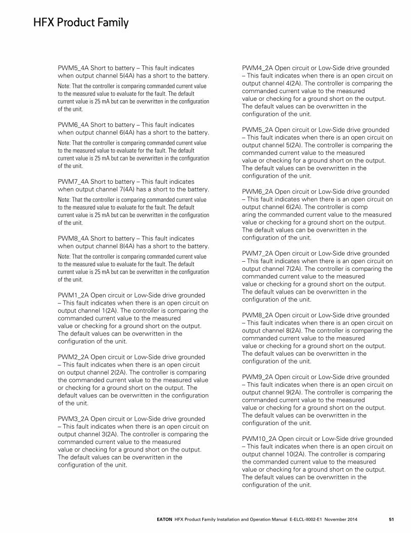
EATON HFX Product Family Installation and Operation Manual E-ELCL-II002-E1 November 2014 51
PWM5_4A Short to battery – This fault indicates when output channel 5(4A) has a short to the battery.
Note: That the controller is comparing commanded current value to the measured value to evaluate for the fault. The default current value is 25 mA but can be overwritten in the configuration of the unit.
PWM6_4A Short to battery – This fault indicates when output channel 6(4A) has a short to the battery.
Note: That the controller is comparing commanded current value to the measured value to evaluate for the fault. The default current value is 25 mA but can be overwritten in the configuration of the unit.
PWM7_4A Short to battery – This fault indicates when output channel 7(4A) has a short to the battery.
Note: That the controller is comparing commanded current value to the measured value to evaluate for the fault. The default current value is 25 mA but can be overwritten in the configuration of the unit.
PWM8_4A Short to battery – This fault indicates when output channel 8(4A) has a short to the battery.
Note: That the controller is comparing commanded current value to the measured value to evaluate for the fault. The default current value is 25 mA but can be overwritten in the configuration of the unit.
PWM1_2A Open circuit or Low-Side drive grounded – This fault indicates when there is an open circuit on output channel 1(2A). The controller is comparing the commanded current value to the measured value or checking for a ground short on the output. The default values can be overwritten in the configuration of the unit.
PWM2_2A Open circuit or Low-Side drive grounded – This fault indicates when there is an open circuit on output channel 2(2A). The controller is comparing the commanded current value to the measured value or checking for a ground short on the output. The default values can be overwritten in the configuration of the unit.
PWM3_2A Open circuit or Low-Side drive grounded – This fault indicates when there is an open circuit on output channel 3(2A). The controller is comparing the commanded current value to the measured value or checking for a ground short on the output. The default values can be overwritten in the configuration of the unit.
PWM4_2A Open circuit or Low-Side drive grounded – This fault indicates when there is an open circuit on output channel 4(2A). The controller is comparing the commanded current value to the measured value or checking for a ground short on the output. The default values can be overwritten in the configuration of the unit.
PWM5_2A Open circuit or Low-Side drive grounded – This fault indicates when there is an open circuit on output channel 5(2A). The controller is comparing the commanded current value to the measured value or checking for a ground short on the output. The default values can be overwritten in the configuration of the unit.
PWM6_2A Open circuit or Low-Side drive grounded – This fault indicates when there is an open circuit on output channel 6(2A). The controller is comp aring the commanded current value to the measured value or checking for a ground short on the output. The default values can be overwritten in the configuration of the unit.
PWM7_2A Open circuit or Low-Side drive grounded – This fault indicates when there is an open circuit on output channel 7(2A). The controller is comparing the commanded current value to the measured value or checking for a ground short on the output. The default values can be overwritten in the configuration of the unit.
PWM8_2A Open circuit or Low-Side drive grounded – This fault indicates when there is an open circuit on output channel 8(2A). The controller is comparing the commanded current value to the measured value or checking for a ground short on the output. The default values can be overwritten in the configuration of the unit.
PWM9_2A Open circuit or Low-Side drive grounded – This fault indicates when there is an open circuit on output channel 9(2A). The controller is comparing the commanded current value to the measured value or checking for a ground short on the output. The default values can be overwritten in the configuration of the unit.
PWM10_2A Open circuit or Low-Side drive grounded – This fault indicates when there is an open circuit on output channel 10(2A). The controller is comparing the commanded current value to the measured value or checking for a ground short on the output. The default values can be overwritten in the configuration of the unit.
HFX Product Family
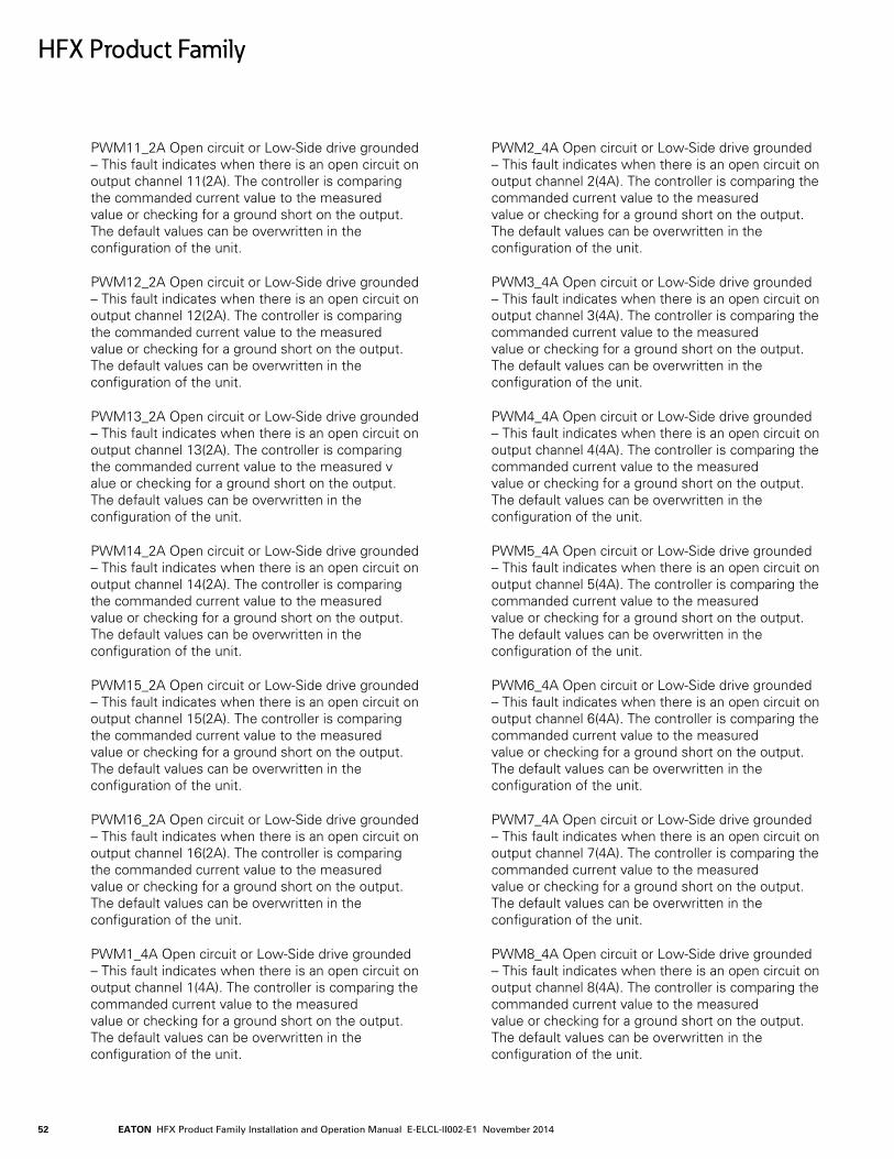
EATON HFX Product Family Installation and Operation Manual E-ELCL-II002-E1 November 201452
PWM11_2A Open circuit or Low-Side drive grounded – This fault indicates when there is an open circuit on output channel 11(2A). The controller is comparing the commanded current value to the measured value or checking for a ground short on the output. The default values can be overwritten in the configuration of the unit.
PWM12_2A Open circuit or Low-Side drive grounded – This fault indicates when there is an open circuit on output channel 12(2A). The controller is comparing the commanded current value to the measured value or checking for a ground short on the output. The default values can be overwritten in the configuration of the unit.
PWM13_2A Open circuit or Low-Side drive grounded – This fault indicates when there is an open circuit on output channel 13(2A). The controller is comparing the commanded current value to the measured v alue or checking for a ground short on the output. The default values can be overwritten in the configuration of the unit.
PWM14_2A Open circuit or Low-Side drive grounded – This fault indicates when there is an open circuit on output channel 14(2A). The controller is comparing the commanded current value to the measured value or checking for a ground short on the output. The default values can be overwritten in the configuration of the unit.
PWM15_2A Open circuit or Low-Side drive grounded – This fault indicates when there is an open circuit on output channel 15(2A). The controller is comparing the commanded current value to the measured value or checking for a ground short on the output. The default values can be overwritten in the configuration of the unit.
PWM16_2A Open circuit or Low-Side drive grounded – This fault indicates when there is an open circuit on output channel 16(2A). The controller is comparing the commanded current value to the measured value or checking for a ground short on the output. The default values can be overwritten in the configuration of the unit.
PWM1_4A Open circuit or Low-Side drive grounded – This fault indicates when there is an open circuit on output channel 1(4A). The controller is comparing the commanded current value to the measured value or checking for a ground short on the output. The default values can be overwritten in the configuration of the unit.
PWM2_4A Open circuit or Low-Side drive grounded – This fault indicates when there is an open circuit on output channel 2(4A). The controller is comparing the commanded current value to the measured value or checking for a ground short on the output. The default values can be overwritten in the configuration of the unit.
PWM3_4A Open circuit or Low-Side drive grounded – This fault indicates when there is an open circuit on output channel 3(4A). The controller is comparing the commanded current value to the measured value or checking for a ground short on the output. The default values can be overwritten in the configuration of the unit.
PWM4_4A Open circuit or Low-Side drive grounded – This fault indicates when there is an open circuit on output channel 4(4A). The controller is comparing the commanded current value to the measured value or checking for a ground short on the output. The default values can be overwritten in the configuration of the unit.
PWM5_4A Open circuit or Low-Side drive grounded – This fault indicates when there is an open circuit on output channel 5(4A). The controller is comparing the commanded current value to the measured value or checking for a ground short on the output. The default values can be overwritten in the configuration of the unit.
PWM6_4A Open circuit or Low-Side drive grounded – This fault indicates when there is an open circuit on output channel 6(4A). The controller is comparing the commanded current value to the measured value or checking for a ground short on the output. The default values can be overwritten in the configuration of the unit.
PWM7_4A Open circuit or Low-Side drive grounded – This fault indicates when there is an open circuit on output channel 7(4A). The controller is comparing the commanded current value to the measured value or checking for a ground short on the output. The default values can be overwritten in the configuration of the unit.
PWM8_4A Open circuit or Low-Side drive grounded – This fault indicates when there is an open circuit on output channel 8(4A). The controller is comparing the commanded current value to the measured value or checking for a ground short on the output. The default values can be overwritten in the configuration of the unit.
HFX Product Family
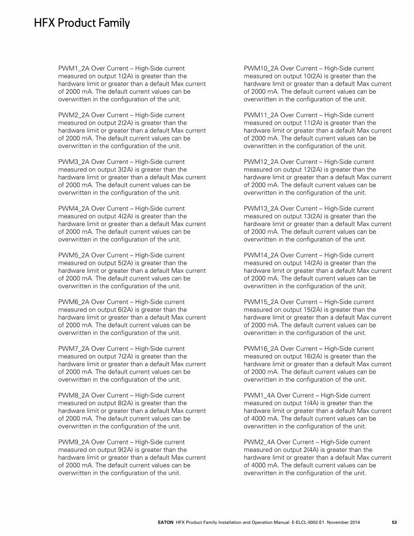
EATON HFX Product Family Installation and Operation Manual E-ELCL-II002-E1 November 2014 53
PWM1_2A Over Current – High-Side current measured on output 1(2A) is greater than the hardware limit or greater than a default Max current of 2000 mA. The default current values can be overwritten in the configuration of the unit.
PWM2_2A Over Current – High-Side current measured on output 2(2A) is greater than the hardware limit or greater than a default Max current of 2000 mA. The default current values can be overwritten in the configuration of the unit.
PWM3_2A Over Current – High-Side current measured on output 3(2A) is greater than the hardware limit or greater than a default Max current of 2000 mA. The default current values can be overwritten in the configuration of the unit.
PWM4_2A Over Current – High-Side current measured on output 4(2A) is greater than the hardware limit or greater than a default Max current of 2000 mA. The default current values can be overwritten in the configuration of the unit.
PWM5_2A Over Current – High-Side current measured on output 5(2A) is greater than the hardware limit or greater than a default Max current of 2000 mA. The default current values can be overwritten in the configuration of the unit.
PWM6_2A Over Current – High-Side current measured on output 6(2A) is greater than the hardware limit or greater than a default Max current of 2000 mA. The default current values can be overwritten in the configuration of the unit.
PWM7_2A Over Current – High-Side current measured on output 7(2A) is greater than the hardware limit or greater than a default Max current of 2000 mA. The default current values can be overwritten in the configuration of the unit.
PWM8_2A Over Current – High-Side current measured on output 8(2A) is greater than the hardware limit or greater than a default Max current of 2000 mA. The default current values can be overwritten in the configuration of the unit.
PWM9_2A Over Current – High-Side current measured on output 9(2A) is greater than the hardware limit or greater than a default Max current of 2000 mA. The default current values can be overwritten in the configuration of the unit.
PWM10_2A Over Current – High-Side current measured on output 10(2A) is greater than the hardware limit or greater than a default Max current of 2000 mA. The default current values can be overwritten in the configuration of the unit.
PWM11_2A Over Current – High-Side current measured on output 11(2A) is greater than the hardware limit or greater than a default Max current of 2000 mA. The default current values can be overwritten in the configuration of the unit.
PWM12_2A Over Current – High-Side current measured on output 12(2A) is greater than the hardware limit or greater than a default Max current of 2000 mA. The default current values can be overwritten in the configuration of the unit.
PWM13_2A Over Current – High-Side current measured on output 13(2A) is greater than the hardware limit or greater than a default Max current of 2000 mA. The default current values can be overwritten in the configuration of the unit.
PWM14_2A Over Current – High-Side current measured on output 14(2A) is greater than the hardware limit or greater than a default Max current of 2000 mA. The default current values can be overwritten in the configuration of the unit.
PWM15_2A Over Current – High-Side current measured on output 15(2A) is greater than the hardware limit or greater than a default Max current of 2000 mA. The default current values can be overwritten in the configuration of the unit.
PWM16_2A Over Current – High-Side current measured on output 16(2A) is greater than the hardware limit or greater than a default Max current of 2000 mA. The default current values can be overwritten in the configuration of the unit.
PWM1_4A Over Current – High-Side current measured on output 1(4A) is greater than the hardware limit or greater than a default Max current of 4000 mA. The default current values can be overwritten in the configuration of the unit.
PWM2_4A Over Current – High-Side current measured on output 2(4A) is greater than the hardware limit or greater than a default Max current of 4000 mA. The default current values can be overwritten in the configuration of the unit.
HFX Product Family

EATON HFX Product Family Installation and Operation Manual E-ELCL-II002-E1 November 201454
PWM3_4A Over Current – High-Side current measured on output 3(4A) is greater than the hardware limit or greater than a default Max current of 4000 mA. The default current values can be overwritten in the configuration of the unit.
PWM4_4A Over Current – High-Side current measured on output 4(4A) is greater than the hardware limit or greater than a default Max current of 4000 mA. The default current values can be overwritten in the configuration of the unit.
PWM5_4A Over Current – High-Side current measured on output 5(4A) is greater than the hardware limit or greater than a default Max current of 4000 mA. The default current values can be overwritten in the configuration of the unit.
PWM6_4A Over Current – High-Side current measured on output 6(4A) is greater than the hardware limit or greater than a default Max current of 4000 mA. The default current values can be overwritten in the configuration of the unit.
PWM7_4A Over Current – High-Side current measured on output 7(4A) is greater than the hardware limit or greater than a default Max current of 4000 mA. The default current values can be overwritten in the configuration of the unit.
PWM8_4A Over Current – High-Side current measured on output 8(4A) is greater than the hardware limit or greater than a default Max current of 4000 mA. The default current values can be overwritten in the configuration of the unit.
PWM1_2A Loss of Control – This fault indicates that current or reverse current exceeding a default 75 mA is flowing without any commanded output current on the channel.
PWM2_2A Loss of Control – This fault indicates that current or reverse current exceeding a default 75 mA is flowing without any commanded output current on the channel
PWM3_2A Loss of Control – This fault indicates that current or reverse current exceeding a default 7 5 mA is flowing without any commanded output current on the channel
PWM4_2A Loss of Control – This fault indicates that current or reverse current exceeding a default 75 mA is flowing without any commanded output current on the channel.
PWM5_2A Loss of Control – This fault indicates that current or reverse current exceeding a default 75 mA is flowing without any commanded output current on the channel.
PWM6_2A Loss of Control – This fault indicates that current or reverse current exceeding a default 75 mA is flowing without any commanded output current on the channel.
PWM7_2A Loss of Control – This fault indicates that current or reverse current exceeding a default 75 mA is flowing without any commanded output current on the channel.
PWM8_2A Loss of Control – This fault indicates that current or reverse current exceeding a default 75 mA is flowing without any commanded output current on the channel.
PWM9_2A Loss of Control – This fault indicates that current or reverse current exceeding a default 75 mA is flowing without any commanded output current on the channel.
PWM10_2A Loss of Control – This fault indicates that current or reverse current exceeding a default 75 mA is flowing without any commanded output current on the channel
PWM11_2A Loss of Control – This fault indicates that current or reverse current exceeding a default 75 mA is flowing without any commanded output current on the channel
PWM12_2A Loss of Control – This fault indicates that current or reverse current exceeding a default 75 mA is flowing without any commanded output current on the channel.
PWM13_2A Loss of Control – This fault indicates that current or reverse current exceeding a default 75 mA is flowing without any commanded output current on the channel.
PWM14_2A Loss of Control – This fault indicates that current or reverse current exceeding a default 75 mA is flowing without any commanded output current on the channel.
PWM15_2A Loss of Control – This fault indicates that current or reverse current exceeding a default 75 mA is flowing without any commanded output current on the channel.
HFX Product Family
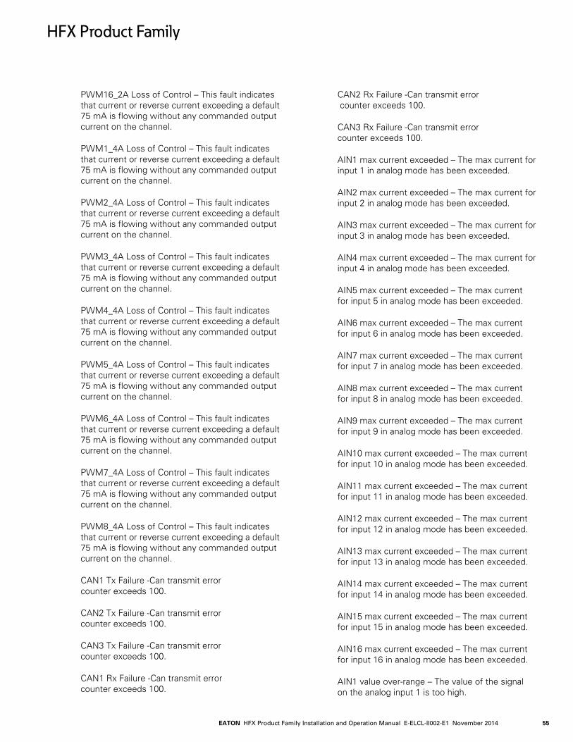
EATON HFX Product Family Installation and Operation Manual E-ELCL-II002-E1 November 2014 55
PWM16_2A Loss of Control – This fault indicates that current or reverse current exceeding a default 75 mA is flowing without any commanded output current on the channel.
PWM1_4A Loss of Control – This fault indicates that current or reverse current exceeding a default 75 mA is flowing without any commanded output current on the channel.
PWM2_4A Loss of Control – This fault indicates that current or reverse current exceeding a default 75 mA is flowing without any commanded output current on the channel.
PWM3_4A Loss of Control – This fault indicates that current or reverse current exceeding a default 75 mA is flowing without any commanded output current on the channel.
PWM4_4A Loss of Control – This fault indicates that current or reverse current exceeding a default 75 mA is flowing without any commanded output current on the channel.
PWM5_4A Loss of Control – This fault indicates that current or reverse current exceeding a default 75 mA is flowing without any commanded output current on the channel.
PWM6_4A Loss of Control – This fault indicates that current or reverse current exceeding a default 75 mA is flowing without any commanded output current on the channel.
PWM7_4A Loss of Control – This fault indicates that current or reverse current exceeding a default 75 mA is flowing without any commanded output current on the channel.
PWM8_4A Loss of Control – This fault indicates that current or reverse current exceeding a default 75 mA is flowing without any commanded output current on the channel.
CAN1 Tx Failure -Can transmit error counter exceeds 100.
CAN2 Tx Failure -Can transmit error counter exceeds 100.
CAN3 Tx Failure -Can transmit error counter exceeds 100.
CAN1 Rx Failure -Can transmit error counter exceeds 100.
CAN2 Rx Failure -Can transmit error counter exceeds 100.
CAN3 Rx Failure -Can transmit error counter exceeds 100.
AIN1 max current exceeded – The max current for input 1 in analog mode has been exceeded.
AIN2 max current exceeded – The max current for input 2 in analog mode has been exceeded.
AIN3 max current exceeded – The max current for input 3 in analog mode has been exceeded.
AIN4 max current exceeded – The max current for input 4 in analog mode has been exceeded.
AIN5 max current exceeded – The max current for input 5 in analog mode has been exceeded.
AIN6 max current exceeded – The max current for input 6 in analog mode has been exceeded.
AIN7 max current exceeded – The max current for input 7 in analog mode has been exceeded.
AIN8 max current exceeded – The max current for input 8 in analog mode has been exceeded.
AIN9 max current exceeded – The max current for input 9 in analog mode has been exceeded.
AIN10 max current exceeded – The max current for input 10 in analog mode has been exceeded.
AIN11 max current exceeded – The max current for input 11 in analog mode has been exceeded.
AIN12 max current exceeded – The max current for input 12 in analog mode has been exceeded.
AIN13 max current exceeded – The max current for input 13 in analog mode has been exceeded.
AIN14 max current exceeded – The max current for input 14 in analog mode has been exceeded.
AIN15 max current exceeded – The max current for input 15 in analog mode has been exceeded.
AIN16 max current exceeded – The max current for input 16 in analog mode has been exceeded.
AIN1 value over-range – The value of the signal on the analog input 1 is too high.
HFX Product Family
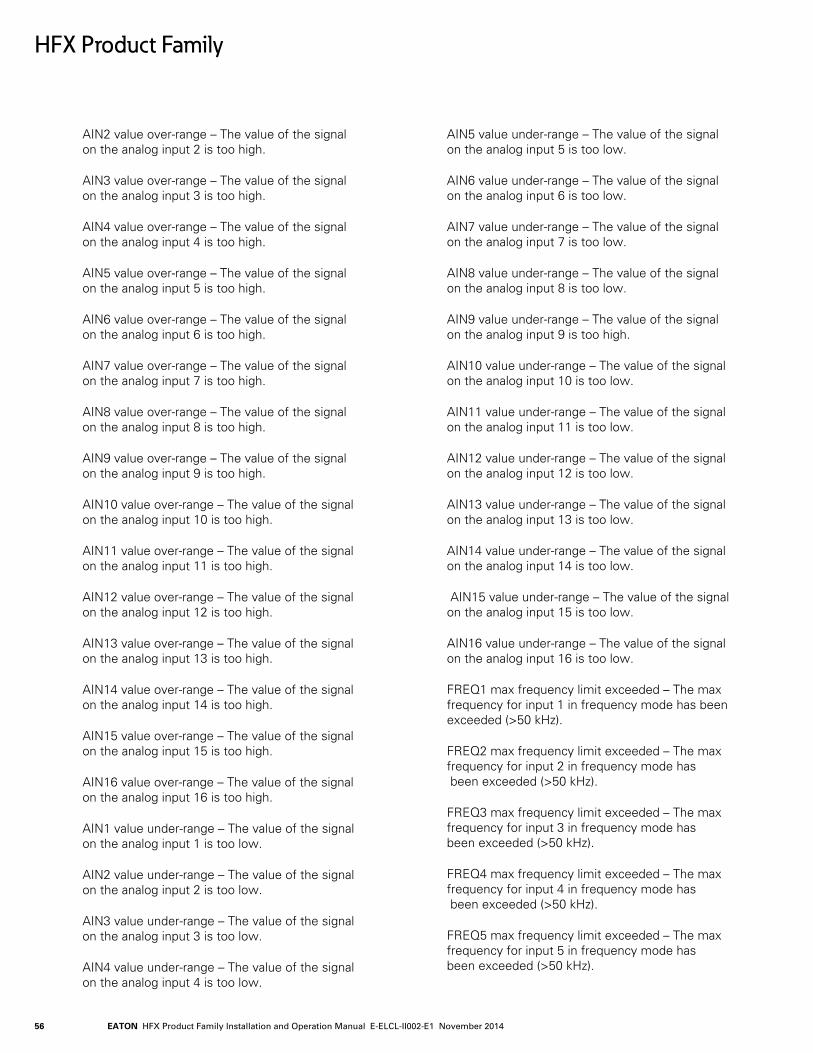
EATON HFX Product Family Installation and Operation Manual E-ELCL-II002-E1 November 201456
AIN2 value over-range – The value of the signal on the analog input 2 is too high.
AIN3 value over-range – The value of the signal on the analog input 3 is too high.
AIN4 value over-range – The value of the signal on the analog input 4 is too high.
AIN5 value over-range – The value of the signal on the analog input 5 is too high.
AIN6 value over-range – The value of the signal on the analog input 6 is too high.
AIN7 value over-range – The value of the signal on the analog input 7 is too high.
AIN8 value over-range – The value of the signal on the analog input 8 is too high.
AIN9 value over-range – The value of the signal on the analog input 9 is too high.
AIN10 value over-range – The value of the signal on the analog input 10 is too high.
AIN11 value over-range – The value of the signal on the analog input 11 is too high.
AIN12 value over-range – The value of the signal on the analog input 12 is too high.
AIN13 value over-range – The value of the signal on the analog input 13 is too high.
AIN14 value over-range – The value of the signal on the analog input 14 is too high.
AIN15 value over-range – The value of the signal on the analog input 15 is too high.
AIN16 value over-range – The value of the signal on the analog input 16 is too high.
AIN1 value under-range – The value of the signal on the analog input 1 is too low.
AIN2 value under-range – The value of the signal on the analog input 2 is too low.
AIN3 value under-range – The value of the signal on the analog input 3 is too low.
AIN4 value under-range – The value of the signal on the analog input 4 is too low.
AIN5 value under-range – The value of the signal on the analog input 5 is too low.
AIN6 value under-range – The value of the signal on the analog input 6 is too low.
AIN7 value under-range – The value of the signal on the analog input 7 is too low.
AIN8 value under-range – The value of the signal on the analog input 8 is too low.
AIN9 value under-range – The value of the signal on the analog input 9 is too high.
AIN10 value under-range – The value of the signal on the analog input 10 is too low.
AIN11 value under-range – The value of the signal on the analog input 11 is too low.
AIN12 value under-range – The value of the signal on the analog input 12 is too low.
AIN13 value under-range – The value of the signal on the analog input 13 is too low.
AIN14 value under-range – The value of the signal on the analog input 14 is too low.
AIN15 value under-range – The value of the signal on the analog input 15 is too low.
AIN16 value under-range – The value of the signal on the analog input 16 is too low.
FREQ1 max frequency limit exceeded – The max frequency for input 1 in frequency mode has been exceeded (>50 kHz).
FREQ2 max frequency limit exceeded – The max frequency for input 2 in frequency mode has been exceeded (>50 kHz).
FREQ3 max frequency limit exceeded – The max frequency for input 3 in frequency mode has been exceeded (>50 kHz).
FREQ4 max frequency limit exceeded – The max frequency for input 4 in frequency mode has been exceeded (>50 kHz).
FREQ5 max frequency limit exceeded – The max frequency for input 5 in frequency mode has been exceeded (>50 kHz).
HFX Product Family

EATON HFX Product Family Installation and Operation Manual E-ELCL-II002-E1 November 2014 57
FREQ6 max frequency limit exceeded – The max frequency for input 6 in frequency mode has been exceeded (>50 kHz).
FREQ7 max frequency limit exceeded – The max frequency for input 7 in frequency mode has been exceeded (>50 kHz).
FREQ8 max frequency limit exceeded – The max frequency for input 8 in frequency mode has been exceeded (>50 kHz).
Max Total input frequency limit exceeded – The maximum aggregate frequency for all frequency inputs in total has been exceeded (>200kHz).
FREQ1 Input over voltage – The max voltage for input 1 in frequency mode has been exceeded (>34 Volts).
FREQ2 Input over voltage – The max voltage for input 2 in frequency mode has been exceeded (>34 Volts)
FREQ3 Input over voltage – The max voltage for input 3 in frequency mode has been exceeded (>34 Volts).
FREQ4 Input over voltage – The max voltage for input 4 in frequency mode has been exceeded (>34 Volts).
FREQ5 Input over voltage – The max voltage for input 5 in frequency mode has been exceeded (>34 Volts).
FREQ6 Input over voltage – The max voltage for input 6 in frequency mode has been exceeded (>34 Volts).
FREQ7 Input over voltage – The max voltage for input 7 in frequency mode has been exceeded (>34 Volts).
FREQ8 Input over voltage – The max voltage for input 8 in frequency mode has been exceeded (>34 Volts).
FREQ1 Input under voltage – The voltage for input 1 in frequency mode is too low. ( < -5 Volts).
FREQ2 Input under voltage – The voltage for input 2 in frequency mode is too low. ( < -5 Volts).
FREQ3 Input under voltage – The voltage for input 3 in frequency mode is too low. ( < 0 Volts).
FREQ4 Input under voltage – The voltage for input 4 in frequency mode is too low. ( < 0 Volts).
FREQ5 Input under voltage – The voltage for input 5 in frequency mode is too low. ( < 0 Volts).
FREQ6 Input under voltage – The voltage for input 6 in frequency mode is too low. ( < 0 Volts).
FREQ7 Input under voltage – The voltage for input 7 in frequency mode is too low. ( < 0 Volts).
FREQ8 Input under voltage – The voltage for input 8 in frequency mode is too low. ( < 0 Volts).
HFX Product Family
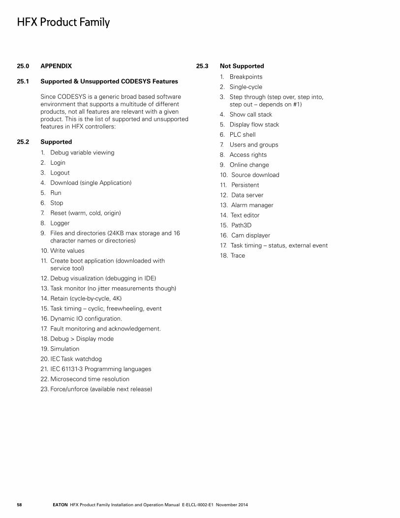
EATON HFX Product Family Installation and Operation Manual E-ELCL-II002-E1 November 201458
25.0 APPENDIX
25.1 Supported & Unsupported CODESYS Features
Since CODESYS is a generic broad based software environment that supports a multitude of different products, not all features are relevant with a given product. This is the list of supported and unsupported features in HFX controllers:
25.2 Supported
1. Debug variable viewing
2. Login
3. Logout
4. Download (single Application)
5. Run
6. Stop
7. Reset (warm, cold, origin)
8. Logger
9. Files and directories (24KB max storage and 16 character names or directories)
10. Write values
11. Create boot application (downloaded with service tool)
12. Debug visualization (debugging in IDE)
13. Task monitor (no jitter measurements though)
14. Retain (cycle-by-cycle, 4K)
15. Task timing – cyclic, freewheeling, event
16. Dynamic IO configuration.
17. Fault monitoring and acknowledgement.
18. Debug > Display mode
19. Simulation
20. IEC Task watchdog
21. IEC 61131-3 Programming languages
22. Microsecond time resolution
23. Force/unforce (available next release)
25.3 Not Supported
1. Breakpoints
2. Single-cycle
3. Step through (step over, step into, step out – depends on #1)
4. Show call stack
5. Display flow stack
6. PLC shell
7. Users and groups
8. Access rights
9. Online change
10. Source download
11. Persistent
12. Data server
13. Alarm manager
14. Text editor
15. Path3D
16. Cam displayer
17. Task timing – status, external event
18. Trace
HFX Product Family
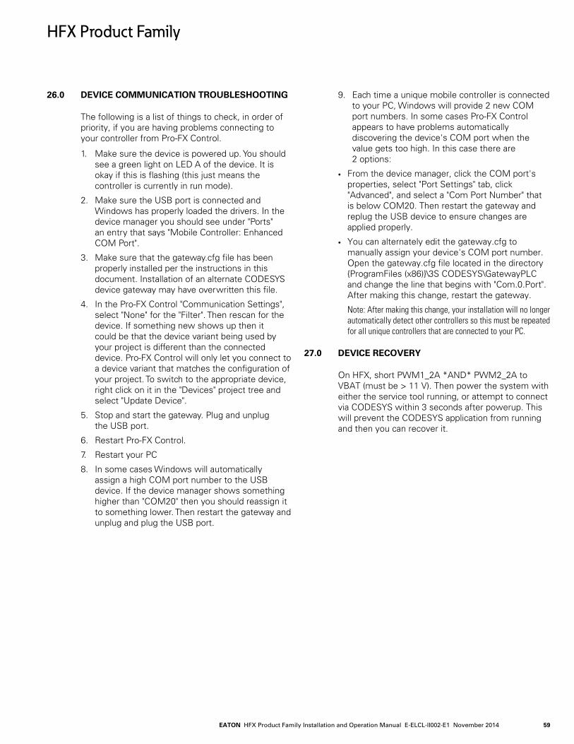
EATON HFX Product Family Installation and Operation Manual E-ELCL-II002-E1 November 2014 59
26.0 DEVICE COMMUNICATION TROUBLESHOOTING
The following is a list of things to check, in order of priority, if you are having problems connecting to your controller from Pro-FX Control.
1. Make sure the device is powered up. You should see a green light on LED A of the device. It is okay if this is flashing (this just means the controller is currently in run mode).
2. Make sure the USB port is connected and Windows has properly loaded the drivers. In the device manager you should see under "Ports" an entry that says "Mobile Controller: Enhanced COM Port".
3. Make sure that the gateway.cfg file has been properly installed per the instructions in this document. Installation of an alternate CODESYS device gateway may have overwritten this file.
4. In the Pro-FX Control "Communication Settings", select "None" for the "Filter". Then rescan for the device. If something new shows up then it could be that the device variant being used by your project is different than the connected device. Pro-FX Control will only let you connect to a device variant that matches the configuration of your project. To switch to the appropriate device, right click on it in the "Devices" project tree and select "Update Device".
5. Stop and start the gateway. Plug and unplug the USB port.
6. Restart Pro-FX Control.
7. Restart your PC
8. In some cases Windows will automatically assign a high COM port number to the USB device. If the device manager shows something higher than "COM20" then you should reassign it to something lower. Then restart the gateway and unplug and plug the USB port.
9. Each time a unique mobile controller is connected to your PC, Windows will provide 2 new COM port numbers. In some cases Pro-FX Control appears to have problems automatically discovering the device's COM port when the value gets too high. In this case there are 2 options:
• From the device manager, click the COM port's properties, select "Port Settings" tab, click "Advanced", and select a "Com Port Number" that is below COM20. Then restart the gateway and replug the USB device to ensure changes are applied properly.
• You can alternately edit the gateway.cfg to manually assign your device's COM port number. Open the gateway.cfg file located in the directory ProgramFiles (x86)\3S CODESYS\GatewayPLC and change the line that begins with "Com.0.Port". After making this change, restart the gateway.
Note: After making this change, your installation will no longer automatically detect other controllers so this must be repeated for all unique controllers that are connected to your PC.
27.0 DEVICE RECOVERY
On HFX, short PWM1_2A *AND* PWM2_2A to VBAT (must be > 11 V). Then power the system with either the service tool running, or attempt to connect via CODESYS within 3 seconds after powerup. This will prevent the CODESYS application from running and then you can recover it.
HFX Product Family
© 2014 EatonAll Rights ReservedPrinted in USADocument No. E-ELCL-II002-E1November 2014
EatonHydraulics Group USA14615 Lone Oak RoadEden Prairie, MN 55344USATel: 952-937-9800Fax: 952-294-7722www.eaton.com/hydraulics
EatonHydraulics Group EuropeRoute de la Longeraie 71110 MorgesSwitzerlandTel: +41 (0) 21 811 4600Fax: +41 (0) 21 811 4601
EatonHydraulics Group Asia PacificEaton BuildingNo.7 Lane 280 Linhong RoadChangning District,Shanghai 200335ChinaTel: (+86 21) 5200 0099Fax: (+86 21) 2230 7240