Eaton Fuller Automated Transmissions - transgearllc.comtransgearllc.com/pdf/TROUBLESHOOT -CEEMAT...
194
For the most current information, visit the Roadranger web site at www.roadranger.com CEEMAT 1X10⁹ Series Eaton Fuller Automated Transmissions ® ® Troubleshooting Guide TRTS-0020 December 1996 TM
Transcript of Eaton Fuller Automated Transmissions - transgearllc.comtransgearllc.com/pdf/TROUBLESHOOT -CEEMAT...

For the most current information, visit the Roadranger web site at www.roadranger.com
CEEMAT1X109 Series
Eaton Fuller Automated Transmissions® ®
Troubleshooting Guide TRTS-0020 December 1996
TM

General Warnings:
Before starting a vehicle:
• Sit in the driver’s seat
• Place shift lever in neutral
• Set the parking brake
Before working on a vehicle or leaving the cab withengine running:
• Place shift lever in neutral
• Set the parking brake
• Block the wheels
Do not release the parking brake or attempt to select agear until the air pressure is at the correct level.
When parking the vehicle or leaving the cab:
• Place shift lever in neutral
• Set the parking brake
To avoid damage to the transmission during towing:
• Place shift lever in neutral
• Lift the drive wheels off of the ground ordisconnect the driveline
Do not operate vehicle if alternator lamp is lit or if gaugesindicate low voltage.
Suggested Tools:
Pressure Gauges:
• 0-300 PSI Hydraulic gauge
• 0-100 PSI Hydraulic gauge
• 0-100 PSI Air gauge
OTC Tool & Equipment Division,SPX Corporation
Eaton Part No. Description
5505027 Volt /Ohm Meter (Standardcommercially available VOM)
For ordering in U.S. and Canada call 1-800-533-0492. (InMinnesota call 507-455-7010.)
MPSI Micro Processor Systems, Inc.
MPSI Part No. Description
104004 Pro-link Main (MPSI hand-held diagnostictool)
205040 Heavy Duty Multi-Protocol Cartridge (MPC)
805001 MPC Eaton Systems Software
For MPSI phone orders call 1-800-639-6774.
Related Publications
Installation Guide - Eaton TRIG-0020
Driver Instructions - Eaton TRDR-0020
Service Manual - Eaton TRSM-0020
Illustrated Parts List - Eaton TRIP-0023 (11109)
Eaton TRIP-0025 (13109)
Eaton TRIP-0022 (14109)
Eaton TRIP-0026 (16109)
For more information call 1-800-826-HELP (826-4357).
Every effort has been made to ensure the accuracy of all information in this manual. However, Eaton Transmission Division makes no expressed or implied warranty or representationbased on the enclosed information. Any errors or omissions may be reported to Training and Publications, Eaton Transmission Division, P.O. Box 4013, Kalamazoo, MI 49003.

1-1
Table of Contents
Component Code 43, Range Solenoid Coil ................ 2-50
Component Code 44, Disc/Inertia BrakeSolenoid Coil ............................................................ 2-52
Component Code 45, Power SynchronizerBand/Engine Boost Solenoid Coil .............................. 2-54
Component Code 51, Center Rail Sensor................... 2-56
Component Code 52, Neutral Sensor ........................ 2-60
Component Code 53, Gear Engaged Sensor .............. 2-64
Component Code 54, HI Range Sensor ..................... 2-68
Component Code 55, LO Range Sensor .................... 2-72
Component Code 56, Input Speed Sensor ................. 2-76
Component Code 57, Output Speed Sensor .............. 2-80
Component Code 61, Autoshifter Solenoid 1Coil .......................................................................... 2-84
Component Code 62, Autoshifter Solenoid 2Coil .......................................................................... 2-86
Component Code 63, Autoshifter Solenoid 3Coil .......................................................................... 2-88
Component Code 64, Autoshifter Solenoid 4Coil .......................................................................... 2-90
System Code 71, Stuck Engaged .............................. 2-92
System Code 72, Failed to Select a Rail ..................... 2-96
System Code 73, Failed to Engage Gear .................. 2-100
System Code 74, Failed to Synchronize ................... 2-104
System Code 81, Invalid Shift Lever at Start(Cable Only) ........................................................... 2-108
Component Code 82, Multiple Non-Adjacent Senors(Cable Only) ........................................................... 2-110
System Code 83, Shift Lever Missing(Cable Only) ........................................................... 2-112
Component Code 83, Shift Lever Missing(Electronic Only) ..................................................... 2-114
Section 1: Introduction
Diagnostics Procedure ............................................... 1-2
Fault Codes Retrieval/Clearing ..................................... 1-3
Driving Techniques ..................................................... 1-4
Fault Code Isolation Procedure Index .......................... 1-8
Symptom Driven Diagnostics ................................... 1-10
Section 2: Fault Isolation Procedures
Pretests
Electrical Pretest ......................................................... 2-1
Pneumatic Pretest ...................................................... 2-3
Power-Up Sequence Test ........................................... 2-4
Component and System Codes
Component Code 11, ECU .......................................... 2-6
Component Code 14, Shift Lever Fault ........................ 2-8
Component Code 15, Shift Lever Data Link ............... 2-10
Component Code 21, Interrupt Solenoid Coil ............. 2-16
Component Code 22, Lockup/BypassSolenoid Coil ............................................................ 2-18
Component Code 23, Engine Speed Sensor .............. 2-20
Component Code 24, Hydraulic System Fault ............ 2-24
Component Code 31, Engine Brake Relay Coil ........... 2-28
Component Code 32, Defuel Solenoid Coil ................ 2-32
Component Code 33, System Voltage ....................... 2-36
Component Code 34, Throttle Position Sensor .......... 2-38
System Code 35, Engine Control Failure(Mechanically-Governed Engines) ............................. 2-42
System Code 35, Engine Control Failure(Electronically-Governed Engines) ............................ 2-44
System Code 41, Range Failed to Engage .................. 2-48

1-2
Table of Contents
Section 3: Symptom Isolation Procedures
Symptom Pretests
Transmission Basic Inputs Pretest .............................. 3-1
Engine Interface Pretest .............................................. 3-5
Symptom Tests
Shift Complaint Test ................................................... 3-7
High Operating Temperature Test ............................. 3-14
Hand-Held Diagnostic Tool Failed to Operate Test ..... 3-17
Shift Lever in Gear Signal Test .................................. 3-20
Neutral Output Test .................................................. 3-22
Splitshaft PTO Switch Test ........................................ 3-24
Quick to Neutral Test ................................................ 3-26
Shift Lever Auxiliary Output 2 Test ............................ 3-27
Shift Lever Auto Neutral Input Test ........................... 3-29
Shift Lever Back Light Test ....................................... 3-30
Reverse Relay Indicator Test ..................................... 3-31
Start Enable Relay Test ............................................. 3-34
Start Enable Relay Latch Test .................................... 3-40
Shift Lever Voltage Test (Driver Lever) ...................... 3-42
Shift Lever Voltage Test (Work Lever) ....................... 3-44
Appendix
Torque Converter Hydraulic Diagram .......................... A-1
Pneumatic Diagram AT, ATR and ATS ......................... A-2
Pneumatic Diagram ATE ............................................. A-3
Pneumatic DiagramMechanical ATE with Throttle Boost ............................ A-4
Cable Shift Lever Wiring Diagram ............................... A-6
Single Station Electronic Shift Lever Wiring Diagram ... A-8
Dual Station Electronic Shift Lever Wiring Diagram ... A-10
Cable Shift Lever Adjustment Procedure ................... A-12
Linear Throttle Position Adjustment Procedure ......... A-14
Electro-Pneumatic Defuel ControlAdjustment Procedure .............................................. A-15
Dual Station Start Enable .......................................... A-16

1-1

1-2
Diagnostics ProcedureFollow the flowchart below for all CEEMAT transmission failures. Perform tests and procedures as directed by the flowchart.
• Perform Electrical Pretest (Page 2-1)
• Perform Power-Up Sequence Test (Page 2-4)
Key on.
Failure detectedduring self-check?
NO
YES
Retrieve active codes. (Page 1-3)
Active codes?
NO
YES
• Refer to the Fault Code Isolation Procedure Index (Page 1-8) to select a fault code isolation procedure
• Perform Electrical Pretest (Page 2-1)
Retrieve inactive codes. (Page 1-3)
Inactive codes?
NO
YES
• Record and clear codes (Page 1-3)• Refer to the Fault Code Isolation
Procedure Index (Page 1-8) to select a fault code isolation procedure
• Perform Electrical Pretest (Page 2-1)• Perform Pneumatic Pretest (Page 2-3)
Symptom?YES
• Perform Electrical Pretest (Page 2-1)• Perform Pneumatic Pretest (Page 2-3)• Perform Transmission Basic Inputs
Pretest (Page 3-1)• Perform Engine Interface Pretest (Page 3-5)• Refer to Symptom Driven Diagnostics
Table (Page 1-10) to select a fault isolation procedure
Test complete.
NO
Introduction

1-3
Fault Codes Retrieval/Clearing
Retrieving Fault Codes
Retrieve CEEMAT fault codes by enabling the CEEMATsystem’s self-diagnostic mode.
Note: You can also use a diagnostic scan tool, such as theMPSI Pro Link Main, to retrieve CEEMAT fault codes. Refer tothe OEM’s documentation for more information.
1. Place the shift lever in neutral.
2. Set the parking brakes.
3. Turn the ignition key on but do not start the engine.
4. To Retrieve Active Codes: Start with the key in the onposition. Turn the key off and on two times within fiveseconds ending with the key in the on position.
To Retrieve Inactive (Intermittent) Codes: Start withthe key in the on position. Turn the key off and on fourtimes within five seconds ending with the key in the onposition.
After a brief pause, the service transmission indicatorlamp begins flashing two-digit fault codes.
5. Observe the sequence of flashes on the indicator lampand record the codes. A one to two second pauseseparates each stored code, and the sequence auto-matically repeats after all codes have been flashed.
Clearing Fault Codes
The following procedure clears all inactive (intermittent) faultcodes from the ECU’s memory. (Active fault codes areautomatically cleared when the fault has been corrected.)
1. Place the shift lever in neutral.
2. Set the parking brakes.
3. Turn the ignition key on but do not start the engine.
4. Start with the key in the on position. Turn the key offand on six times within five seconds ending with thekey in the on position.
Introduction
4 times
off on
2 times
off on
6 times
off on
2 Flashes 1 Flash
Shortpause
(1/2 sec)
Shortpause
(1/2 sec)
(1–2 sec)
3 Flashes 1 Flash
Code 21 Code 31
Diagnostics ProcedureFault Codes Retrieval/Clearing

1-4
Driving Techniques
FaultCodes
Description Type of Code Driving Technique
11 ECU Component Key on. If the fault is present, the system shouldautomatically detect the problem and set the code. If the fault is not present at key on, operate the vehicle and attempt to duplicate the driving conditions that triggered the fault code. Possible triggers include heat and vibration.
14 Shift Lever Fault Component Key on. If the fault is present, the system shouldautomatically detect the problem and set the code. If the fault is not present at key on, operate the vehicle and attempt to duplicate the driving conditions that triggered the fault code. Possible triggers include heat, vibration andselecting different shift lever positions.
15 Shift Lever Data Link Component Key on. If the fault is present, the system shouldautomatically detect the problem and set the code. If the fault is not present at key on, operate the vehicle and attempt to duplicate the driving conditions that triggered the fault code. Possible triggers include heat and vibration.
21 Interrupt Solenoid Coil Component Key on. If the fault is present, the system shouldautomatically detect the problem and set the code. If the fault is not present at key on, operate the vehicle and attempt to duplicate the driving conditions that triggered the fault code. Possible triggers include heat and vibration.
22 Lockup/Bypass Solenoid Component Key on. If the fault is present, the system shouldCoil automatically detect the problem and set the code.
If the fault is not present at key on, operate the vehicle and attempt to duplicate the driving conditions that triggered the fault code. Possible triggers include heat and vibration.
23 Engine Speed Sensor Component Operate the vehicle above 4th gear until the fault occurs.Maintain a steady speed. If may be necessary to operatethe vehicle for a prolonged period of time if the cause ofthe failure is related to heat or vibration.
24 Hydraulic System Fault Component Complete several automatic shifts while driving the vehiclethrough terrain that loads the engine.
31 Engine Brake Relay Coil Component Key on. If the fault is present, the system shouldautomatically detect the problem and set the code. If the fault is not present at key on, operate the vehicle and attempt to duplicate the driving conditions that triggered the fault code. Possible triggers include heat and vibration.
32 Defuel Solenoid Coil Component Key on. If the fault is present, the system shouldautomatically detect the problem and set the code. If the fault is not present at key on, operate the vehicle and attempt to duplicate the driving conditions that triggered the fault code. Possible triggers include heat and vibration.
Introduction

1-5
Driving Techniques, continued
FaultCodes
Description Type of Code Driving Technique
33 System Voltage Component Key on. If the fault is present, the system shouldautomatically detect the problem and set the code. If the fault is not present at key on, operate the vehicle and attempt to duplicate the driving conditions that triggered the fault code. Possible triggers include heat and vibration.
34 Throttle Position Sensor Component Key on. If the fault is present, the system shouldautomatically detect the problem and set the code. If the fault is not present at key on, operate the vehicle and attempt to duplicate the driving conditions that triggered the fault code. Possible triggers include heat, vibration andvarying levels of throttle demand.
35 Engine Control Failure System Operate the vehicle and shift the transmission up and down(Mechanically-Governed through the gears.Engines)
35 Engine Control Failure System Key on. If the fault is present, the system should(Electronically-Governed automatically detect the problem and set the code.Engines) If the fault is not present at key on, operate the vehicle and
attempt to duplicate the driving conditions that triggered the fault code. Possible triggers include heat, vibration andvarying levels of throttle demand.
41 Range Failed to Engage System Operate the vehicle and perform several range upshifts and downshifts. The failure is detected after 5 consecutiveattempts to complete the same type of range shift. Severalshifts (ten or more) may be necessary before the ECUconfirms the failure.
43 Range Solenoid Coil Component Key on. If the fault is present, the system shouldautomatically detect the problem and set the code. If the fault is not present at key on, operate the vehicle and attempt to duplicate the driving conditions that triggered the fault code. Possible triggers include heat and vibration.
44 Disc/Inertia Brake Coil Component Key on. If the fault is present, the system shouldautomatically detect the problem and set the code. If the fault is not present at key on, operate the vehicle and attempt to duplicate the driving conditions that triggered the fault code. Possible triggers include heat and vibration.
45 Power Synchronizer Component Key on. If the fault is present, the system shouldBand/Engine Boost automatically detect the problem and set the code. Solenoid Coil If the fault is not present at key on, operate the vehicle and
attempt to duplicate the driving conditions that triggered the fault code. Possible triggers include heat and vibration.
51 Center Rail Sensor Component Complete several front box gear shifts, including selections from NEUTRAL and automatic shifts while in motion.
IntroductionDriving Techniques

1-6
Driving Techniques, continued
FaultCodes
Description Type of Code Driving Technique
52 Neutral Sensor Component Complete several front box gear shifts, including selections from NEUTRAL and automatic shifts while in motion.
53 Gear Engaged Sensor Component Complete several front box gear shifts, including selections from NEUTRAL and automatic shifts while in motion.
54 HI Range Sensor Component Complete several range shifts up and down across the entire range while the vehicle is in motion.
55 LO Range Sensor Component Complete several range shifts up and down across the entire range while the vehicle is in motion.
56 Input Speed Sensor Component Select a forward gear and drive at a steady speed for at least two minutes.
57 Output Speed Sensor Component Select a forward gear and drive at a steady speed for at least two minutes.
61 Autoshifter Solenoid 1 Component Key on. If the fault is present, the system shouldCoil automatically detect the problem and set the code.
If the fault is not present at key on, operate the vehicle and attempt to duplicate the driving conditions that triggered the fault code. Possible triggers include heat and vibration.
62 Autoshifter Solenoid 2 Component Key on. If the fault is present, the system shouldCoil automatically detect the problem and set the code.
If the fault is not present at key on, operate the vehicle and attempt to duplicate the driving conditions that triggered the fault code. Possible triggers include heat and vibration.
63 Autoshifter Solenoid 3 Component Key on. If the fault is present, the system shouldCoil automatically detect the problem and set the code.
If the fault is not present at key on, operate the vehicle and attempt to duplicate the driving conditions that triggered the fault code. Possible triggers include heat and vibration.
64 Autoshifter Solenoid 4 Component Key on. If the fault is present, the system shouldCoil automatically detect the problem and set the code.
If the fault is not present at key on, operate the vehicle and attempt to duplicate the driving conditions that triggered the fault code. Possible triggers include heat and vibration.
Introduction

1-7
Driving Techniques, continued
FaultCodes
Description Type of Code Driving Technique
71 Stuck Engaged System Engage LO gear and allow the vehicle to slowly move forward. While the vehicle is in motion, move the shift lever to Reverse LO and slowly bring the vehicle to a stop. The vehicle will shift into Reverse LO. Several shifts (ten or more) may be required before the ECU confirms the failure.
72 Failed to Select a Rail System Complete several shifts while the vehicle is in motion, including selections from neutral. Also allow the transmission to complete several automatic shifts.
73 Failed to Engage Gear System Complete several shifts while the vehicle is in motion, including selections from neutral. Also allow the trans-mission to complete several automatic shifts.
74 Failed to Synchronize System Operate the vehicle at high speeds while shifting the transmission between 7th, 8th and 9th gears. Since the transmission makes several calculations before setting code 71, ten or more shifts may be required before the ECU confirms the failure.
81 Invalid Shift Lever at System Key on. If the fault is present, the system shouldStart (Cable Only) automatically detect the problem and set the code.
If the fault is not present at key on, operate the vehicle and attempt to duplicate the driving conditions that triggered the fault code. Possible triggers include heat and vibration.
82 Multiple Non-Ajacent Component Key on. If the fault is present, the system shouldSensors (Cable Only) automatically detect the problem and set the code.
If the fault is not present at key on, operate the vehicle and attempt to duplicate the driving conditions that triggered the fault code. Possible triggers include heat, vibration and varying levels of shift lever positions.
83 Shift Lever Missing System Key on. If the fault is present, the system should (Cable Only) automatically detect the problem and set the code.
If the fault is not present at key on, operate the vehicle and attempt to duplicate the driving conditions that triggered the fault code. Possible triggers include heat, vibration or different lever positions.
83 Shift Lever Missing Component Key on. If the fault is present, the system should (Electronic Only) automatically detect the problem and set the code.
If the fault is not present at key on, operate the vehicle and attempt to duplicate the driving conditions that triggered the fault code. Possible triggers include heat, vibration or different lever positions.
IntroductionDriving Techniques

1-8
FaultCodes
Description Type of Code Page Number
11 ECU Component 2-6
14 Shift Lever Fault Component 2-8
15 Shift Lever Data Link Component 2-10
21 Interrupt Solenoid Coil Component 2-16
22 Lockup/Bypass Solenoid Coil Component 2-18
23 Engine Speed Sensor Component 2-20
24 Hydraulic System Fault Component 2-24
31 Engine Brake Relay Coil Component 2-28
32 Defuel Solenoid Coil Component 2-32
33 System Voltage Component 2-36
34 Throttle Position Sensor Component 2-38
35 Engine Control Failure (Mechanically-Governed Engines) System 2-42
35 Engine Control Failure (Electronically-Governed Engines) System 2-44
41 Range Failed to Engage System 2-48
43 Range Solenoid Coil Component 2-50
44 Disc/Inertia Brake Solenoid Coil Component 2-52
45 Power Synchronizer Band/Engine Boost Solenoid Coil Component 2-54
51 Center Rail Sensor Component 2-56
Fault Code Isolation Procedure Index
Introduction

1-9
FaultCodes
Description Type of Code Page Number
52 Neutral Sensor Component 2-60
53 Gear Engaged Sensor Component 2-64
54 HI Range Sensor Component 2-68
55 LO Range Sensor Component 2-72
56 Input Speed Sensor Component 2-76
57 Output Speed Sensor Component 2-80
61 Autoshifter Solenoid 1 Coil Component 2-84
62 Autoshifter Solenoid 2 Coil Component 2-86
63 Autoshifter Solenoid 3 Coil Component 2-88
64 Autoshifter Solenoid 4 Coil Component 2-90
71 Stuck Engaged System 2-92
72 Failed to Select a Rail System 2-96
73 Failed to Engage Gear System 2-100
74 Failed to Synchronize System 2-104
81 Invalid Shift Lever at Start (Cable Only) System 2-108
82 Multiple Non-Anjacent Sensors (Cable Only) Component 2-110
83 Shift Lever Missing (Cable Only) System 2-112
83 Shift Lever Missing (Electronic Only) Component 2-114
Fault Code Isolation Procedure Index, continued
IntroductionFault Code Isolation Procedure Index

1-10
Symptom Driven Diagnostics
Symptom Isolation Procedure Page Number
Shift complaint
High operating temperature
Hand-held diagnostic tool failed to operate properly
Shift lever in gear signal not functioning properly
Neutral output not functioning properly
Splitshaft PTO switch not functioning properly
Quick to neutral not functioning properly
Shift lever auxiliary output 2 not functioning properly
Shift lever auto neutral input not functioning properly
Shift lever back light not functioning properly
Reverse relay indicator not functioning properly
Start enable relay not functioning properly
Start enable relay latch not functioning properly
Shift lever voltage (Driver lever) not functioning properly
Shift lever voltage (Work lever) not functioning properly
Shift Complaint Test 3-7
High Operating Temperature Test 3-14
Hand-Held Diagnostic Tool Test 3-17
Shift Lever In Gear Signal Test 3-20
Neutral Output Test 3-22
Splitshaft PTO Switch Test 3-24
Quick to Neutral Test 3-26
Shift Lever Auxiliary Output 2 Test 3-27
Shift Lever Auto Neutral Input Test 3-29
Shift Lever Back Light Test 3-30
Reverse Relay Indicator Test 3-31
Start Enable Relay Test 3-34
Start Enable Relay Latch Test 3-40
Shift Lever Voltage Test (Driver Lever) 3-42
Shift Lever Voltage Test (Work Lever) 3-44
Introduction
2-1
Fault Isolation Procedures
1. Key off.2. Measure battery voltage at the battery terminals. If voltage is 11 to 13 volts
If voltage is outside of range
Go to Step B.
Repair or replace battery and/or charging system as required. Repeat this step.
Step A
If voltage is within 1 volt of battery voltage
If voltage is outside of range
Go to Step C.
Repair or replace vehicle interface harness, batterycircuit breaker or battery circuit as required. Repeat this step.
Electrical Pretest
Procedure Condition Action
1. Key off.2. Disconnect vehicle interface harness from CEEMAT.3. Measure voltage between vehicle interface harness pin L and battery negative (–) terminal.
Step B Procedure Condition Action
Step C Procedure Condition Action
1. Key on.2. Measure voltage between vehicle interface harness pin K and ground. If voltage is within
1 volt of battery voltage
If voltage is outside of range
Go to Step D.
Repair or replace vehicleinterface harness, ignitioncircuit breaker or ignition circuit as required. Repeat this step.
B A M
C P N L
D R V U
E S T J
K
F G H
VOLTS
V COM A
+–
VOLTS
V COM A
B A M
C P N L
D R V U
E S T J
K
F G H
VOLTS
V COM A
Ground
+–
Electrical Pretest

2-2
Fault Isolation Procedures
Electrical Pretest, continued
Step D Procedure Condition Action
1. Key off.2. Disconnect positive battery cable.3. Measure resistance between vehicle interface harness pin:
• B and battery negative (–) terminal.
• C and battery negative (–) terminal. If resistance is 0 to .3 ohms
If resistance is outside of range
Test complete.
Repair or replace vehicleinterface harness or ground connections as required. Repeat this step.
B A M
C P N L
D R V U
E S T J
K
F G H
OHMS
V COM A
+–
B A M
C P N L
D R V U
E S T J
K
F G H
OHMS
V COM A
+–

2-3
Fault Isolation Procedures
1. Key off.2. Install a 0-150 PSI air gauge in the regulated test port of the CEEMAT air filter/regulator.3. Start engine.4. Allow air pressure to build to governor cutoff.5. Read vehicle main air pressure gauge. If air pressure cuts off at
90 to 120 PSI
If air pressure is outside ofrange
Go to Step B.
Repair vehicle air system as required. Repeat this step.
Step A
If vehicle maintains air pressure
If vehicle loses air pressure
Go to Step C.
Repair leak in vehicle air system. Repeat this step.
Pneumatic Pretest
Procedure Condition Action
1. Key off.2. Monitor air pressure on vehicle main air pressure gauge.
Step B Procedure Condition Action
Step C Procedure Condition Action
1. Read air pressure gauge installed in the air filter/regulator. If air pressure is 75 to 85 PSI
If air pressure is outside ofrange
Test complete.
Go to Step D.
Step D Procedure Condition Action
1. Key off.2. Remove air supply line to the air filter/regulator and check air flow. If air flows from the supply line
If air does not flow from the supply line
Replace air filter/regulator. Go to Step C.
Repair vehicle air supply to air filter/regulator. Go to Step C.
Regulated test port
Pneumatic Pretest

2-4
Fault Isolation Procedures
1. Key on.2. Observe service transmission lamp. If service transmission lamp
lights for one second and goes off
If service transmission lamp never comes on
If service transmission lamp is on steady
Test complete.
Go to Step B.
Go to Step C.
Step A
Power-Up Sequence Test
Procedure Condition Action
Step B Procedure Condition Action
1. Key off.2. Disconnect vehicle interface harness from CEEMAT.3. Place jumper wire across vehicle interface harness pins G and B. If service transmission lamp
turns on
If service transmission lamp never comes on
Replace ECU.Go to Step A.
Repair or replace vehicle interface harness as required. Go to Step A.
B A M
C P N L
D R V U
E S T J
K
F G H
Step C Procedure Condition Action
1. Key on.2. Disconnect vehicle interface connector at CEEMAT. If service transmission lamp
turns off
If service transmission lamp remains on
Replace ECU.Go to Step A.
Repair or replace vehicle interface harness as required. Go to Step A.

2-5
Fault Isolation Procedures
This Page left blank intentionally
Power-Up Sequence Test

2-6
Fault Isolation Procedures
Component Code 11ECU
Fault Description
This code indicates an electrical problem inside the electricalcontrol unit which is part of the ECU.
Required Tools
• CEEMAT Troubleshooting Guide
Possible Causes
This code can be caused by any of the following conditions:
• Improper configuration software
• Faulty ECU
ECU
Likely Failed Components

2-7
Fault Isolation Procedures
1. Key on.2. Retrieve codes (see page 1-3). If code 11 is active
If code 11 is inactive
Replace ECU.
Test complete.
Step A
Code 11, ECU Test
Condition ActionProcedure
Code 11

2-8
Fault Isolation Procedures
Component Code 14Shift Lever Fault
Fault Description
This code indicates an electrical problem inside the electronicshift lever. The ECU detects this failure when it receives faultinformation from the electronic shift lever.
Required Tools
• Basic Hand Tools
• CEEMAT Troubleshooting Guide
Possible Causes
This code is likely caused by a faulty shift lever.
Electronic shift lever (ESL)
Likely Failed Component

2-9
Fault Isolation Procedures
1. Key on.2. Retrieve codes (see page 1-3). If code 14 is active
If code 14 is inactive
Replace electronic shift lever.
Test complete.
Step A
Code 14, Shift Lever Fault Test
Condition ActionProcedure
Code 14

2-10
Fault Isolation Procedures
Component Code 15Shift Lever Data Link
Fault Description
This code indicates the CEEMAT ECU did not receive anupdated shift lever status signal from the electronic shift levervia the J-1922 data link.
Required Tools
• Basic Hand Tools
• Digital Volt/Ohm Meter
• CEEMAT Troubleshooting Guide
Possible Causes
This code can be caused by any of the following conditions:
• Faulty J-1922 data link
• No electrical power to shift lever
• Faulty shift lever
• Faulty ECU
Likely Failure Locations
W4 ATA (+)W3 ATA(-)W7 Eng BrakeW15 Aux 1 InputW16 Service Light GroundW1B Service Light (+)W6 Service BrakeW1C Service Brake (+)W1 Ignition Power
J1
ECU
Pres
s
Neut
Out
TPS
GND
Fuse
Defu
el
PTO A B
Typical vehicle interface harness
(OEM supplied)
Electronic shift lever (ESL)
ECUTypical shift lever harness
(OEM supplied)
W25 AUX_IN
W1 VIGN
W24 LAMP_GND
W2 VBAT W13 GND
W28 AUX_OUT2 W27 AUX_OUT1

2-11
Fault Isolation Procedures
1. Select the lever to be tested (driver or work lever).2. Key off.3. Disconnect connector from electronic shift lever.4. Disconnect positive battery cable5. Measure resistance between electronic shift lever harness pin B1 and battery negative (–) terminal. If resistance is 0 to .3 ohms
If resistance is outside of range
Go to Step B.
Repair ground.Go to Step V.
Step A
If voltage is within 1 volt of battery voltage
If voltage is outside of range
Go to Step C.
Repair harness to shift lever connector.Go to Step V.
1. Measure voltage between electronic shift lever harness pins A5 and B1.
Code 15, Shift Lever Data Link Test
Procedure Condition Action
Step B Procedure Condition Action
If voltage is 0
If voltage is not 0
Go to Step D.
Repair short to power or incorrectly wired circuit (should be ignition power).Go to Step V.
1. Measure voltage between electronic shift lever harness pins A7 and B1.
Step C Procedure Condition Action
OHMS
V COM A
+–
1 2 3 4 5 6 7 8 9 10 11 12A
B
A
B
VOLTS
V COM A
1 2 3 4 5 6 7 8 9 10 11 12A
B
A
B
VOLTS
V COM A
1 2 3 4 5 6 7 8 9 10 11 12A
B
A
B
Code 15

2-12
Fault Isolation Procedures
Code 15, Shift Lever Data Link Test, continued
If voltage is within 1 volt of battery voltage
If voltage is outside of range
Go to Step E.
Repair ignition power line. Go to Step V.
1. Key on.2. Measure voltage between electronic shift lever harness pins A7 and B1.
Step D Procedure Condition Action
If resistance is 0 to .3 ohms
If resistance is outside of range
Go to Step F.
Repair open circuit between pins B9 and B3. Go to Step V.
1. Measure resistance between electronic shift lever harness pins B9 and B3.
Step E Procedure Condition Action
One shift lever
Two shift levers
Go to Step H.
Go to Step G.
1. Check to see if there are two shift levers.
Step F Procedure Condition Action
VOLTS
V COM A
1 2 3 4 5 6 7 8 9 10 11 12A
B
A
B
OHMS
V COM A
1 2 3 4 5 6 7 8 9 10 11 12A
B
A
B

2-13
Fault Isolation Procedures
Code 15, Shift Lever Data Link Test, continued
If voltage is +3.0 to +4.0 volts
If voltage is outside of range
Go to Step I.
Go to Step J.
1. Key off.2. Disconnect J-1922 data link
from engine ECM.3. Disconnect harness from electronic shift lever.4. Connect hand-held diagnostic tool.5. Key on.6. Select Perform Tests.7. Select Throttle Dip Test.8. Measure voltage between electronic shift lever pins A9 and A10 (connect positive lead to A10).
Step H Procedure Condition Action
If resistance is more than10K ohms or infinite
If resistance is less than10K ohms
Go to Step H.
Both levers selected. Repair wiring harness to pin B9 to ensure infinite resistance on non-selected lever. Go to Step V.
1. Disconnect connector from second electronic shift lever.2. Measure resistance between electronic shift lever harness pin B9 and ground.
Step G Procedure Condition Action
OHMS
V COM A
GROUND
1 2 3 4 5 6 7 8 9 10 11 12A
B
A
B
VOLTS
V COM A
1 2 3 4 5 6 7 8 9 10 11 12A
B
A
B
Code 15

2-14
Fault Isolation Procedures
Code 15, Shift Lever Data Link Test, continued
If resistance is 0 to .3 ohms
If resistance is outside of range
Go to Step K.
Repair or replace J-1922 data link between electronic shift lever and CEEMAT.Go to Step V.
1. Disconnect vehicle interface harness from CEEMAT.2. Measure resistance between vehicle interface harness pin A and shift lever harness pin A10.
3. Measure resistance between vehicle interface harness pin P and shift lever harness pin A9.
Step J Procedure Condition Action
If voltage changes to–3.0 to –4.0 volts
If voltage does not change to –3.0 to –4.0 volts
Replace shift lever.Go to Step V.
Go to Step J.
1. Activate Throttle Dip Test.
Step I Procedure Condition Action
OHMS
V COM A
B A M
C P N L
D R V U
E S T J
K
F G H
1 2 3 4 5 6 7 8 9 10 11 12A
B
A
B
OHMS
V COM A
B A M
C P N L
D R V U
E S T J
K
F G H
1 2 3 4 5 6 7 8 9 10 11 12A
B
A
B

2-15
Fault Isolation Procedures
Code 15, Shift Lever Data Link Test, continued
Step K Procedure Condition Action
1. Measure resistance between vehicle interface harness pins:
• A to ground• P to ground
If resistance is more than 10K ohms or infinite
If resistance is less than 10K ohms
Replace ECU. Go to Step V.
Repair or replace vehicle interface harness. Go to Step V.
Step V Procedure Condition Action
1. Key off.2. Reconnect all connectors.3. Key on.4. Clear codes (see Clearing Fault Codes, page 1-3).5. Use Driving Technique
to attempt to reset the code (page 1-4).
6. Check for codes (see Retrieving Fault Codes, page 1-3). If no codes
If code 15 appears
If code other than 15 appears
Test complete.
Return to Step Ato find error in testing.
Go to Fault Isolation Procedure Index (page 1-8).
OHMS
V COM A
GROUND
B A M
C P N L
D R V U
E S T J
K
F G H
OHMS
V COM A
GROUND
B A M
C P N L
D R V U
E S T J
K
F G H
Code 15

2-16
Fault Isolation Procedures
Component Code 21Interrupt Solenoid Coil
Fault Description
This code indicates an electrical problem in the interruptsolenoid circuit.
Required Tools
• Basic Hand Tools
• Digital Volt/Ohm Meter
• CEEMAT Troubleshooting Guide
Possible Causes
This code can be caused by any of the following conditions:
• Damaged torque converter harness
• Interrupt solenoid coil open or shorted
• Faulty ECU
Likely Failed Components
ECUTorque converter
harness

2-17
Fault Isolation Procedures
1. Key off.2. Disconnect torque converter harness from ECU.3. Measure resistance between
torque converter harnesspins F and G. If resistance is 2.5 to 5.0 ohms
If resistance is outside of range
Go to Step B.
Replace torque converter harness. Go to Step V.
Step A
If resistance is more than 10K ohms or infinite
If resistance is less than 10K ohms
Replace ECU. Go to Step V.
Replace torqueconverter harness.Go to Step V.
1. Measure resistance between torque converter
harness pin F and ground.
Code 21, Interrupt Solenoid Coil Test
Procedure Condition Action
Step B Procedure Condition Action
Step V Procedure Condition Action
E D C
F G H
A B
OHMS
V COM A
E D C
F G H
A B
OHMS
V COM A
GROUND
1. Key off.2. Reconnect all connectors.3. Key on.4. Clear codes (see Clearing Fault Codes, page 1-3).5. Use Driving Technique
to attempt to reset the code (page 1-4).
6. Check for codes (see Retrieving Fault Codes, page 1-3). If no codes
If code 21 appears
If code other than 21 appears
Test complete.
Return to Step Ato find error in testing.
Go to Fault Isolation Procedure Index (page 1-8).
Code 21

2-18
Fault Isolation Procedures
Component Code 22Lockup/Bypass Solenoid Coil
Fault Description
This code indicates an electrical problem in the lockup clutchsolenoid circuit.
Required Tools
• Basic Hand Tools
• Digital Volt/Ohm Meter
• CEEMAT Troubleshooting Guide
Possible Causes
This code can be caused by any of the following conditions:
• Damaged torque converter harness
• Lockup/Bypass solenoid coil open or shorted
• Faulty ECU
Likely Failed Components
ECUTorque converter
harness

2-19
Fault Isolation Procedures
1. Key off.2. Disconnect torque converter harness from ECU.3. Measure resistance between
torque converter harnesspins B and H. If resistance is 2.5 to 5.0 ohms
If resistance is outside of range
Go to Step B.
Replace torque converter harness. Go to Step V.
Step A
If resistance is more than 10K ohms or infinite
If resistance is less than 10K ohms
Replace ECU. Go to Step V.
Replace torqueconverter harness.Go to Step V.
1. Measure resistance between torque converter
harness pin B and ground.
Code 22, Lockup/Bypass Solenoid Coil Test
Procedure Condition Action
Step B Procedure Condition Action
Step V Procedure Condition Action
E D C
F G H
A B
OHMS
V COM A
E D C
F G H
A B
OHMS
V COM A
GROUND
1. Key off.2. Reconnect all connectors.3. Key on.4. Clear codes (see Clearing Fault Codes, page 1-3).5. Use Driving Technique
to attempt to reset the code (page 1-4).
6. Check for codes (see Retrieving Fault Codes, page 1-3). If no codes
If code 22 appears
If code other than 22 appears
Test complete.
Return to Step Ato find error in testing.
Go to Fault Isolation Procedure Index (page 1-8).
Code 22

2-20
Fault Isolation Procedures
Component Code 23Engine Speed Sensor
Fault Description
This code indicates an electrical problem in the engine speedsensor circuit. The signal from the sensor did not match thecurrent CEEMAT operating conditions.
Required Tools
• Hand Tools
• Digital Volt/Ohm Meter
• CEEMAT Troubleshooting Guide
Possible Causes
This code can be caused by any of the following conditions:
• Electrical open or short in the speed sensor circuit
• Faulty speed sensor harness or connector
• Incorrect speed sensor installation
• Incorrect configuration software
• Faulty ECU
ECUTorque converter
harnessEngine speed sensorharness connector
Engine speed sensor
Likely Failed Components

2-21
Fault Isolation Procedures
1. Key off.2. Disconnect engine speed sensor
from torque converter harness.3. Measure resistance between
engine speed sensor pins A and B. If resistance is 3K to 4K ohms
If resistance is outside of range
Go to Step B.
Replace engine speed sensor. Go to Step V.
Step A
Code 23, Engine Speed Sensor Test
Procedure Condition Action
Step B Procedure Condition Action
1. Reconnect engine speed sensor.2. Disconnect torque converter
harness from CEEMAT.3. Measure resistance between
torque converter harness pins A and E. If resistance is 3K to 4K ohms
If resistance is outside of range
Go to Step D.
Repair or replace torque converter harness as required. Go to Step V.
Step C Procedure Condition Action
A
OHMS
V COM A
B
1. Measure resistance between engine speed sensor pin A and ground.
A
OHMS
V COM A
B
GROUND
If resistance is more than10K ohms or infinite
If resistance is less than10K ohms
Go to Step C.
Replace engine speed sensor. Go to Step V.
E D C
F G H
A B
OHMS
V COM A
Code 23

2-22
Fault Isolation Procedures
Code 23, Engine Speed Sensor Test, continued
Step D Procedure Condition Action
1. Measure resistance between torque converter harness pin E and ground. If resistance is more than
10K ohms or infinite
If resistance is less than10K ohms
Replace ECU. Go to Step V.
Repair or replace torque converter harness as required. Go to Step V.
Step V Procedure Condition Action
E D C
F G H
A B
OHMS
V COM A
GROUND
1. Key off.2. Reconnect all connectors.3. Key on.4. Clear codes (see Clearing Fault Codes, page 1-3).5. Use Driving Technique
to attempt to reset the code (page 1-4).
6. Check for codes (see Retrieving Fault Codes, page 1-3). If no codes
If code 23 appears
If code other than 23 appears
Test complete.
Return to Step Ato find error in testing.
Go to Fault Isolation Procedure Index (page 1-8).

2-23
Fault Isolation Procedures
This Page left blank intentionally
Code 23

2-24
Fault Isolation Procedures
Component Code 24Hydraulic System Fault
Fault Description
This code indicates a problem in the CEEMAT hydraulicsystem. The ECU detected excessive slip across the torqueconverter.
Required Tools
• Basic Hand Tools
• Hand-Held Diagnostic Tool
• 0-300 PDI Hydraulic Gauges
• 0-100 PSI Hydraulic Gauge
• CEEMAT Troubleshooting Guide
Possible Causes
This code can be caused by any of the following conditions:
• Low fluid level
• Low fluid pressure
• Excessive slip across the converter
• Faulty interrupt or lockup clutch
• Faulty hydraulic valve
Likely Failed Component and Diagnostic Port Locations
Interrupt clutch
Bypass(Lockup clutch) Main Lube
Torqueconverter

2-25
Fault Isolation Procedures
Code 24 Hydraulic System Fault Test Note: This test is identical to the basic hydraulic test.
1. Key off. 2. Install 0-300 PSI hydraulic
gauges into diagnostic ports for:• Main• Interrupt clutch• Lockup/ bypass clutch
3. Install a 0-100 PSI hydraulic gauge into the lube diagnostic port.
4. Start engine and allow air pressure to build to governor cutoff.
5. Turn PTO off (if equipped).6. With engine at idle, monitor
gauges. If pressure readings are:• Main = 225 to 255 PSI• Interrupt = 0 PSI of main• Lockup/bypass = 0 PSI• Lube = 15 to 35 PSI
If pressure readings are not in the ranges shown above
Go to Step C.
Replace the hydraulic valve. Go to Step V.
Step B Procedure Condition Action
1. Key on.2. Place transmission in neutral.3. Allow engine to idle at 600 to 700 RPM for a minimum of 2 minutes. Ensure transmission fluid temperature is 60 to 120° F.4. Check transmission fluid level. If fluid level is at or above
the COLD-FULL mark
If fluid level is below the COLD-ADD mark
Go to Step B.
Correct fluid level, check for leaks. Go to Step V.
Step A Procedure Condition Action
Code 24

2-26
Fault Isolation Procedures
Code 24 Hydraulic System Fault Test, continued
Step D Procedure Condition Action
1. Select Lockup Test.2. Activate the Lockup Test.3. Monitor the gauges. If pressure readings are:
Main = 225 to 255 PSI Interrupt = 0 PSI Lockup/bypass = ± 5 PSI of Main Lube = 15 to 35 PS
If pressure readings are not in the ranges shown above
Replace transmission. Go to Step V.
Replace the hydraulic valve. Go to Step V.
Step V Verify normal operation Condition Action
1. Review or repeat Steps C and D.
2. Test drive vehicle. If pressure readings are OK and vehicle operates normally
If pressure readings are wrong or vehicle does not operate normally
Test complete.
Go to Step A.
Step C Procedure Condition Action
1. Connect hand-held diagnostic tool.2. Select Perform Tests.3. Select Hydraulic Tests.4. Select Interrupt Test.5. Activate the Interrupt Test.6. Monitor the gauges. If pressure readings are:
• Main = 225 to 255 PSI• Interrupt = ±5 PSI of main• Lockup/bypass = 0 PSI• Lube = 15 to 35 PSI
If pressure readings are not in the ranges shown above
Go to Step D.
Replace the hydraulic valve. Go to Step V.

2-27
Fault Isolation Procedures
This Page left blank intentionally
Code 24

2-28
Fault Isolation Procedures
Component Code 31Engine Brake Relay Coil
Fault Description
This code indicates an electrical problem in the engine brakerelay circuit.
Required Tools
• Basic Hand Tools
• Digital Volt/Ohm Meter
• CEEMAT Troubleshooting Guide
Possible Causes
This code can be caused by an electrical open or short in anyof the following areas:
• Engine brake relay
• Vehicle interface harness
• Faulty ECU
W4 ATA (+)W3 ATA(-)W7 Eng BrakeW15 Aux 1 InputW16 Service Light GroundW1B Service Light (+)W6 Service BrakeW1C Service Brake (+)W1 Ignition Power
Gree
n
Brow
n
Ground To CEEMATTransmissionECU Conn J-1Terminal F
Pink 30Green 86Gray 87aBrown 85
���J1
ECU
Pres
s
Neut
Out
TPS
GND
Fuse
Defu
el
PTO A B
Likely Failed Components
ECU
Typical vehicle harness
(OEM supplied)
Typical engine brake relay
(OEM supplied)

2-29
Fault Isolation Procedures
1. Key off.2. Disconnect vehicle interface
harness from transmission.3. Measure resistance between vehicle interface harness
pins F and B. If resistance is 40 to 90 ohms
If resistance is outside of range
Go to Step B.
Inspect and repair or replace vehicle interface harness or engine brake relay. Go to Step V.
Step A
Code 31, Engine Brake Relay Coil Test
Procedure Condition Action
Step B Procedure Condition Action
B A M
C P N L
D R V U
E S T J
K
F G H
OHMS
V COM A
1. Measure resistance between vehicle interface harness pin F and ground. If resistance more than
10K ohms or infinite
If resistance is less than 10K ohms
Replace ECU. Go to Step V.
Inspect and repair or replace vehicle interface harness or engine brake relay. Go to Step V.
B A M
C P N L
D R V U
E S T J
K
F G H
OHMS
V COM A
GROUND
Code 31

2-30
Fault Isolation Procedures
Code 31, Engine Brake Relay Coil Test, continued
Step V Procedure Condition Action
1. Key off.2. Reconnect all connectors.3. Key on.4. Clear codes (see Clearing Fault Codes, page 1-3).5. Use Driving Technique
to attempt to reset the code (page 1-4).
6. Check for codes (see Retrieving Fault Codes, page 1-3). If no codes
If code 31 appears
If code other than 31 appears
Test complete.
Return to Step Ato find error in testing.
Go to Fault Isolation Procedure Index (page 1-8).

2-31
Fault Isolation Procedures
This Page left blank intentionally
Code 31

2-32
Fault Isolation Procedures
Kit S-2254 (12V) S-2474 (24V)
Throttle controlcylinder(OEM supplied)
W4 ATA (+)W3 ATA(-)W7 Eng BrakeW15 Aux 1 InputW16 Service Light GroundW1B Service Light (+)W6 Service BrakeW1C Service Brake (+)W1 Ignition Power
J1
ECU
Pres
s
Neut
Out
TPS
GND
Fuse
Defu
el
PTO A B
Possible Causes
This code can be caused by an electrical short or open in anyof the following areas:
• Defuel solenoid coil
• Vehicle interface harness
• Faulty ECU
Component Code 32Defuel Solenoid Coil
Fault Description
This code indicates an electrical problem in the defuelsolenoid coil circuit.
Required Tools
• Basic Hand Tools
• Digital Volt/Ohm Meter
• CEEMAT Troubleshooting Guide
Likely Failed Components
Air throttle control
Typical vehicle interface harness(OEM supplied)
Electro hydraulic defuel control(OEM supplied)
Electro-pneumatic
defuel control
ECU

2-33
Fault Isolation Procedures
1. Key off.2. Disconnect vehicle interface harness from defuel solenoid coil.3. Measure resistance between coil pins. If electro-pneumatic or air
throttle coil resistance is 13 to 18 ohms and
Electro-mechanical or air throttle coil resistance is 2.5 to 5.0 ohms
If resistance is outside of range
Go to Step B.
Replace defuel solenoid.Go to Step V.
Step A
If resistance is more than 10K ohms or infinite
If resistance is less than 10K ohms
Go to Step C.
Replace defuel solenoid.Go to Step V.
1. Measure resistance between defuel solenoid coil harness
terminal A and ground.
Code 32, Defuel Solenoid Coil Test
Procedure Condition Action
Step B Procedure Condition Action
A
OHMS
V COM A
B
A
OHMS
V COM A
B
GROUND
1. Reconnect defuel solenoid coil to interface harness.2. Disconnect vehicle interface harness from ECU.3. Measure resistance between vehicle interface harness pins H and B. If electro-pneumatic coil
resistance is 13 to 18 ohmsand
Electro-mechanical coil resistance is 2.5 to 5.0 ohms
If resistance is outside of range
Go to Step D.
Repair or replace vehicleinterface harness as required. Go to Step V.
Step C Procedure Condition Action
B A M
C P N L
D R V U
E S T J
K
F G H
OHMS
V COM A
Code 32

2-34
Fault Isolation Procedures
If resistance is more than 10K ohms or infinite
If resistance is less than 10K ohms
Replace ECU. Go to Step V.
Repair or replace vehicle interface harness. Go to Step V.
1. Measure resistance between vehicle interface harness pin H and ground.
Code 32, Defuel Solenoid Coil Test, continued
Step D Procedure Condition Action
Step V Procedure Condition Action
B A M
C P N L
D R V U
E S T J
K
F G H
OHMS
V COM A
GROUND
1. Key off.2. Reconnect all connectors.3. Key on.4. Clear codes (see Clearing Fault Codes, page 1-3).5. Use Driving Technique
to attempt to reset the code (page 1-4).
6. Check for codes (see Retrieving Fault Codes, page 1-3). If no codes
If code 32 appears
If code other than 32 appears
Test complete.
Return to Step Ato find error in testing.
Go to Fault Isolation Procedure Index (page 1-8).

2-35
Fault Isolation Procedures
This Page left blank intentionally
Code 32

2-36
Fault Isolation Procedures
Component Code 33System Voltage
Fault Description
This code indicates low or no battery power in the vehicleinterface harness. The ECU has detected that battery power isless than nine volts.
Required Tools
• Basic Hand Tools
• Digital Volt/Ohm Meter
• CEEMAT Troubleshooting Guide
Possible Causes
This code can be caused by any of the following conditions:
• Vehicle batteries or charging system
• Battery bus fuse circuit breaker open
• Damaged vehicle interface harness
• Faulty ECU
Likely Failed Components
Typical vehicle interface harness
(OEM supplied)
W4 ATA (+)W3 ATA(-)W7 Eng BrakeW15 Aux 1 InputW16 Service Light GroundW1B Service Light (+)W6 Service BrakeW1C Service Brake (+)W1 Ignition Power
J1
ECU
Pres
s
Neut
Out
TPS
GND
Fuse
Defu
el
PTO A B
ECU

2-37
Fault Isolation Procedures
1. Key on.2. Retrieve codes (page 1-3). If code 33 is active
If code 33 is inactive
Perform Electrical Preteston page 2-1.
Test complete..
Step A
Code 33, System Voltage Test
Test battery voltage Condition Action
Code 33

2-38
Fault Isolation Procedures
Component Code 34Throttle Position Sensor
Fault Description
This code indicates an electrical problem in the throttleposition sensor circuit.
Required Tools
• Basic Hand Tools
• Digital Volt/Ohm Meter
• CEEMAT Troubleshooting Guide
Possible Causes
This code can be caused by and electrical short or open in anyof the following areas:
• Throttle position sensor
• Vehicle interface harness
• Faulty ECU
Likely Failed Components
Typical vehicle interface harness(OEM supplied)
Linear TPS
Air throttle integral TPS(OEM supplied)
ECU
W4 ATA (+)W3 ATA(-)W7 Eng BrakeW15 Aux 1 InputW16 Service Light GroundW1B Service Light (+)W6 Service BrakeW1C Service Brake (+)W1 Ignition Power
J1
ECU
Pres
s
Neut
Out
TPS
GND
Fuse
Defu
el
PTO A B
C B
A

2-39
Fault Isolation Procedures
If A and C resistance is 2K to 15K ohms and
A and B resistance increases smoothly while opening throttleand
B and C resistance decreases smoothly while opening throttleand
C and ground resistance is 50K to infinity
If any of the above conditions are not met
Go to Step B.
Repair or replace throttle position sensor. Go to Step V.
1. Disconnect vehicle interface harness from throttle position sensor. Measure resistance between sensor pins:
• A and C• A and B while opening throttle• B and C while opening throttle• C and ground
Code 34, Throttle Postition Sensor Test
Step A Procedure Condition Action
C B A
OHMS
V COM A
C B A
OHMS
V COM A
C B A
OHMS
V COM A
C B A
OHMS
V COM A
GROUND
Code 34

2-40
Fault Isolation Procedures
If J and U resistance is 2K to 15K ohms and
T and U resistance increases smoothly while opening throttleand
J and T resistance decreases smoothly while opening throttleand
J and ground resistance is 50K to infinity
If any of the above conditions are not met
Replace ECU. Go to Step V.
Repair or replace vehicle interface harness. Go to Step V.
1. Reconnect throttle position sensor.2. Disconnect vehicle interface harness from CEEMAT.3. Measure resistance between harness pins:
• J and U• T and U• J and T• J and ground
Code 34, Throttle Postition Sensor Test, continued
Step B Procedure Condition Action
B A M
C P N L
D R V U
E S T J
K
F G H
OHMS
V COM A
B A M
C P N L
D R V U
E S T J
K
F G H
OHMS
V COM A
B A M
C P N L
D R V U
E S T J
K
F G H
OHMS
V COM A
GROUND
B A M
C P N L
D R V U
E S T J
K
F G H
OHMS
V COM A
2-41
Fault Isolation Procedures
Code 34, Throttle Postition Sensor Test, continued
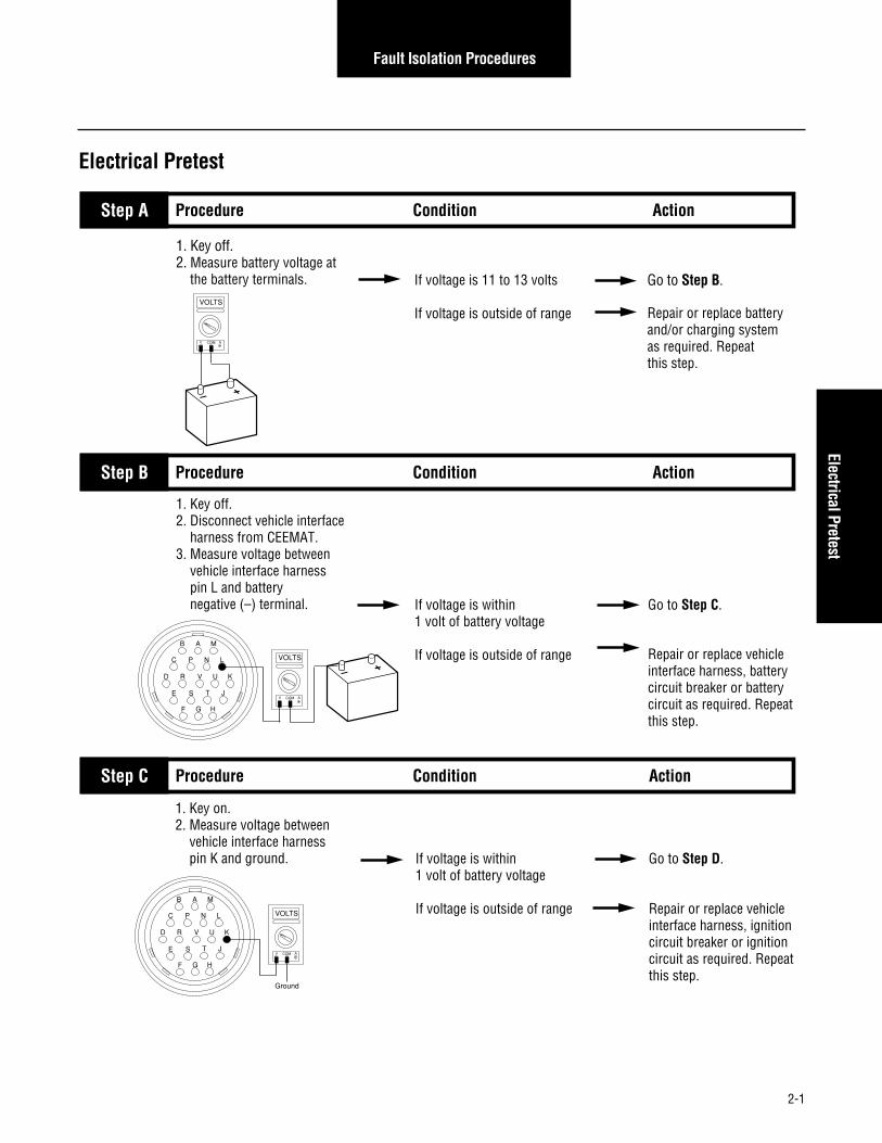
Step V Procedure Condition Action
1. Key off.2. Reconnect all connectors.3. Key on.4. Clear codes (see Clearing Fault Codes, page 1-3).5. Use Driving Technique
to attempt to reset the code(page 1-4).
6. Check for codes (see Retrieving Fault Codes,
page 1-3). If no codes
If code 34 appears
If code other than 34 appears
Test complete.
Return to Step Ato find error in testing.
Go to Fault Isolation Procedure Index (page 1-8).
Code 34

2-42
Fault Isolation Procedures
System Code 35Engine Control Failure(Mechanically-Governed Engines)
Fault Description
This code indicates the engine failed to properly respond tothrottle control during a transmission shift.
Required Tools
• Basic Hand Tools
• Hand-Held Diagnostic Tool
• CEEMAT Troubleshooting Guide
Possible Causes
This code can be caused by any of the following conditions:
• Low air pressure
• Contaminated air supply
• Air leak
• Engine idle adjusted too high
• Faulty defuel solenoid coil
• Throttle control system out of adjustment
• Faulty boost solenoid (air throttle only)Likely Failure Locations
Kit S-2254 (12V) S-2474 (24V)
Throttle controlcylinder(OEM supplied)
Electro hydraulic defuel control(OEM supplied)
Electro-pneumatic
defuel control
Air throttle control
ECU

2-43
Fault Isolation Procedures
1. Start engine and allow to idle.2. Connect hand-held diagnostic
tool.3. Select Perform Tests.4. Select Throttle Dip Test.5. Run engine speed up to
governed RPM and activate Throttle Dip Test.6. Measure the time required
for the RPM to drop to 1000 RPM. If engine RPM dropped
more than 275 RPM per second and throttle dip test did not abort
If engine RPM dropped less than 275 RPM per second
Step A
Code 35, Engine Control Failure Test (Mechanically-Governed Engines)Note: Do not use this test on vehicles using electronic communication for throttle dip.
Procedure Condition Action
Test complete.
Inspect and adjust or repair defuel systemas needed. If vehicle is equipped with an electro-pneumatic defuel system, see Appendix for procedure. Repeat this step.
Code 35

2-44
Fault Isolation Procedures
System Code 35Engine Control Failure(Electronically-Governed Engines)
Fault Description
This code indicates the CEEMAT failed to receive informationfrom the engine or the engine failed to properly respond tothrottle control during a shift as commanded by the engineJ-1922 data link.
Required Tools
• Basic Hand Tools
• Hand-Held Diagnostic Tool
• Digital Volt/Ohm Meter
• CEEMAT Troubleshooting Guide
Possible Causes
This code can be caused by any of the following conditions:
• Faulty J-1922 data link
• Faulty vehicle interface harness or connections
• Faulty engine harness or connections
• Excessive radio interference
• Faulty engine ECM
• Faulty engine fuel pump
• Faulty ECU
W4 ATA (+)W3 ATA(-)W7 Eng BrakeW15 Aux 1 InputW16 Service Light GroundW1B Service Light (+)W6 Service BrakeW1C Service Brake (+)W1 Ignition Power
J1
ECU
Pres
s
Neut
Out
TPS
GND
Fuse
Defu
el
PTO A B
Typical vehicle interface harness(OEM supplied)
ECU
DDEC III ECM Cummins ECM CAT ECM(OEM supplied)
Likely Failure Locations

2-45
Fault Isolation Procedures
1. Key on.2. Disconnect electronic shift lever (if equipped)3. Disconnect J-1922 data link (attached to vehicle interface harness).4. Connect hand-held diagnostic tool.5. Select Perform Tests.6. Select Throttle Dip Test.7. On the CEEMAT side of the data link, measure voltage between pins A and B (connect (+) positive
test lead to A). This connector is typically located at the engine. If voltage is +3.0 to +4.0
If voltage is outside of range
Go to Step B.
Go to Step C.
Step A
If voltage changes to –3.0 to–4.0 volts
If voltage does not change to –3.0 to –4.0 volts
CEEMAT ECU is OK. See OEM manuals to check engine ECM and harness. Go to Step V.
Go to Step C.
1. Activate Throttle Dip Test.
Code 35, Engine Control Failure Test (Electronically-Governed Engine)
Procedure Condition Action
Step B Procedure Condition Action
A
VOLTS
V COM A
B
A B
If resistance is 0 to .3 ohms
If resistance is outside of range
Go to Step D.
Repair or replace vehicle interface harness.Go to Step V.
1. Key off.2. Disconnect vehicle harness
from CEEMAT.3. Measure resistance between
vehicle interface harness pin A and J-1922 data link pin A,
typically located at the engine.
Step C Procedure Condition Action
B A M
C P N L
D R V U
E S T J
K
F G H OHMS
V COM A
Code 35

2-46
Fault Isolation Procedures
Code 35, Engine Control Failure Test (Electronically-Governed Engine), continued
Step D Procedure Condition Action
1. Measure resistance between vehicle harness interface pin P
and J-1922 data link pin B. If resistance is 0 to .3 ohms
If resistance is outside of range
Go to Step E.
Repair or replace vehicleinterface harness. Go to Step V.
B A M
C P N L
D R V U
E S T J
K
F G H
OHMS
V COM A
A B
Step E Procedure Condition Action
1. Measure resistance between vehicle harness interface pins:• A to ground• P to ground
If resistance is more than10K ohms or infinite
If resistance is less than 10K ohms
Replace ECU. Go to Step V.
Repair or replace vehicleinterface harness. Go to Step V.
B A M
C P N L
D R V U
E S T J
K
F G H
OHMS
V COM A
GROUND
B A M
C P N L
D R V U
E S T J
K
F G H
OHMS
V COM A
GROUND

2-47
Fault Isolation Procedures
Step V Procedure Condition Action
1. Key off.2. Reconnect all connectors.3. Key on.4. Clear codes (see Clearing Fault Codes, page 1-3).5. Use Driving Technique
to attempt to reset the code (page 1-4).
6. Check for codes (see Retrieving Fault Codes, page 1-3). If no codes
If code 35 appears
If code other than 35 appears
Repairs complete.
Return to Step Ato find error in testing.
Go to Fault Isolation Procedure Index (page 1-8).
Code 35, Engine Control Failure Test (Electronically-Governed Engine), continued
Code 35

2-48
Fault Isolation Procedures
System Code 41Range Failed to Engage
Fault Description
This code indicates the transmission is unable to complete ashift across the range. The range is either stuck in HI or LO,or cannot complete engagement in HI or LO.
Required Tools
• Basic Hand Tools
• Air Pressure Gauges (0-100 PSI)
• CEEMAT Troubleshooting Guide
• Hand-Held Diagnostic Tool
Possible Causes
This code can be caused by any of the following conditions:
• Low air pressure
• Contaminated air supply
• Air leak
• Range solenoid stuck
• Failed range synchronizer
• Failed range actuator/cylinder/piston/yoke
• Dragging power synchronizer band
• Failed range slave valve
Likely Failure Locations
LO range pressure air line
HI range pressure air line
Air filter/regulatorRange cylinder
Synchronizerair lines
Powersynchronizer
band line
Rangevalve
ECU

2-49
Fault Isolation Procedures
1. Install (in a “T” fashion) 0-100 PSI air gauges into the range air lines.2. Start vehicle and allow air pressure to reach governor cut-off.3. Connect hand-held diagnostic tool and select perform tests. 4. Select air system.5. Select Range System Test.6. Activate Test. In HI range, if HI gauge is
regulated air pressure and LOgauge is zero, and
In LO range, if LO gauge isregulated air pressure and HIgauge is zero
If gauges do not read as described above
Repair auxiliary sectionas required and retest.
Repair range valve on sideof ECU. If problem continues,replace ECU and retest.
Step A
Code 41, Range Failed to Engage Test
Procedure Condition Action
Code 41

2-50
Fault Isolation Procedures
Component Code 43Range Solenoid Coil
Fault Description
This code indicates an electrical problem in the rangesolenoid.
Required Tools
• Basic Hand Tools
• Digital Volt/Ohm Meter
• CEEMAT Troubleshooting Guide
Possible Causes
The code can be caused by an electrical open or short in oneof the following areas:
• Shift bar housing cover harness
• Range solenoid coil
• Faulty ECU
Likely Failed Components
Cover harnessconnector
Range solenoidECU

2-51
Fault Isolation Procedures
1. Key off.2. Remove ECU from transmission.3. Disconnect cover harness from ECU.4. Measure resistance between cover harness pins 1 and 2. If resistance is 11 to 18 ohms
If resistance is outside of range
Go to Step B.
Replace cover harness.Go to Step V.
Step A
If resistance is more than10K ohms or infinite
If resistance is less than10K ohms
Replace ECU. Go to Step V.
Replace cover harness.Go to Step V.
1. Measure resistance between cover harness pin 1 and ground.
Code 43, Range Solenoid Coil Test
Procedure Condition Action
Step B Procedure Condition Action
Step V Procedure Condition Action
1. Key off.2. Reconnect all connectors.3. Key on.4. Clear codes (see Clearing Fault Codes, page 1-3).5. Use Driving Technique
to attempt to reset the code (Page 1-4).
6. Check for codes (see Retrieving Fault Codes, page 1-3). If no codes
If code 43 appears
If code other than 43 appears
Test complete.
Return to Step Ato find error in testing.
Go to Fault Isolation Procedure Index (Page 1-8).
6 5 4
123
OHMS
V COM A
6 5 4
123
OHMS
V COM A
GROUND
Code 43
2-52
Fault Isolation Procedures
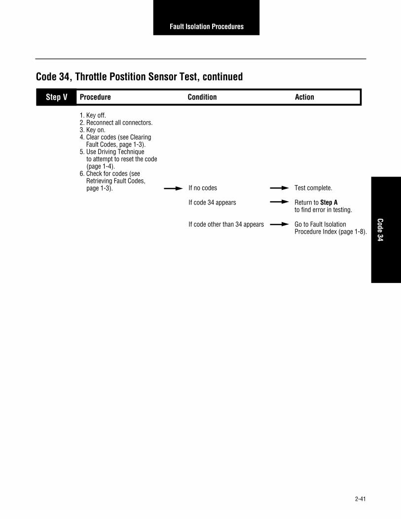
Component Code 44Disc/Inertia Brake Solenoid Coil
Fault Description
This code indicates an electrical problem in the disk/inertiabrake.
Required Tools
• Basic Hand Tools
• Digital Volt/Ohm Meter
• CEEMAT Troubleshooting Guide
Likely Failed Components
Cover harnessconnector
Disc/inertia brake solenoidECU
Possible Causes
This code can be caused by an electrical open or short in oneof the following areas:
• Shift bar housing cover harness
• Disc/inertia brake solenoid coil
• Faulty ECU

2-53
Fault Isolation Procedures
1. Key off.2. Remove ECU from transmission.3. Disconnect cover harness from ECU.4. Measure resistance between cover harness pins 5 and 6. If resistance is 11 to 18 ohms
If resistance is outside of range
Go to Step B.
Replace cover harness.Go to Step V.
Step A
If resistance is more than10K ohms or infinite
If resistance is less than10K ohms
Replace ECU. Go to Step V.
Replace cover harness.Go to Step V.
1. Measure resistance between cover harness pin 5 and ground.
Code 44, Disc/Inertia Brake Solenoid Coil Test
Procedure Condition Action
Step B Procedure Condition Action
Step V Procedure Condition Action
1. Key off.2. Reconnect all connectors.3. Key on.4. Clear codes (see Clearing Fault Codes, page 1-3).5. Use Driving Technique
to attempt to reset the code (page 1-4).
6. Check for codes (see Retrieving Fault Codes, page 1-3). If no codes
If code 44 appears
If code other than 44 appears
Test complete.
Return to Step Ato find error in testing.
Go to Fault Isolation Procedure Index (page 1-8).
6 5 4
123
OHMS
V COM A
6 5 4
123
OHMS
V COM A
GROUND
Code 44

2-54
Fault Isolation Procedures
Component Code 45Power Synchronizer Band/EngineBoost Solenoid Coil
Fault Description
This code indicates an electrical problem in the band/engineboost solenoid.
Required Tools
• Basic Hand Tools
• Digital Volt/Ohm Meter
• CEEMAT Troubleshooting Guide
Likely Failed Components
Cover harnessconnector
Power sychronizer band/engine boost solenoid
ECU
Possible Causes
The code can be caused by an electrical open or short in oneof the following areas:
• Shift bar housing cover harness
• Power synchronizer band/engine boost solenoid coil
• Faulty ECU

2-55
Fault Isolation Procedures
1. Key off.2. Remove ECU from transmission.3. Disconnect cover harness from ECU.4. Measure resistance between cover harness pins 3 and 4. If resistance is 11 to 18 ohms
If resistance is outside of range
Go to Step B.
Replace cover harness.Go to Step V.
Step A
If resistance is more than 10K ohms or infinite
If resistance is less than 10K ohms
Replace ECU. Go to Step V.
Replace cover harness.Go to Step V.
1. Measure resistance between cover harness pin 3 and ground.
Code 45, Power Synchronizer Band/Engine Boost Solenoid Coil Test
Procedure Condition Action
Step B Procedure Condition Action
Step V Procedure Condition Action
1. Key off.2. Reconnect all connectors.3. Key on.4. Clear codes (see Clearing Fault Codes, page 1-3).5. Use Driving Technique
to attempt to reset the code (page 1-4).
6. Check for codes (see Retrieving Fault Codes, page 1-3). If no codes
If code 45 appears
If code other than 45 appears
Test complete.
Return to Step Ato find error in testing.
Go to Fault Isolation Procedure Index (page 1-8).
6 5 4
123
OHMS
V COM A
6 5 4
123
OHMS
V COM A
GROUND
Code 45

2-56
Fault Isolation Procedures
Component Code 51Center Rail Sensor
Fault Description
This code indicates an electrical problem in the center railsensor circuit.
Required Tools
• Basic Hand Tools
• Digital Volt/Ohm Meter
• CEEMAT Troubleshooting Guide
Likely Failed Components
Autoshifterharness
Autoshifter
Center rail sensor (S1)
ECU
Possible Causes
This code can be caused by an electrical open or short in anyof the following areas:
• Center rail sensor
• Autoshifter wiring harness
• Autoshifter
• Faulty ECU

2-57
Fault Isolation Procedures
1. Key off.2. Remove ECU from transmission.3. Disconnect autoshifter harness from ECU.4. Inspect harness and position sensor connections for abrasions or corrosion. If harness and connections
are OK
If harness or connections have poor connections, abrasions or corrosion
Go to Step B.
Repair connections asneeded. Repeat this step.
Step A
If resistance is 0 to .3 ohms
If resistance is outside of range
Go to Step C.
Repair or replace autoshifter harness.Go to Step V.
1. Disconnect connector on the gearbox center switch (S1).2. Install a jumper wire between the two sensor pins.3. Measure resistance between autoshifter harness terminals W and D.
Code 51, Center Rear Sensor Test
Procedure Condition Action
Step B Procedure Condition Action
If resistance is more than10K ohms or infinite
If resistance is less than10K ohms
Go to Step D.
Repair or replace autoshifter harness. Go to Step V.
1. With the jumper still connected, measure resistance between autoshifter harness terminal W and ground.
Step C Procedure Condition Action
L
A
J
XK
P
D
C
B
O
N
M
G
S
F
RQ
E
V
U
T
H
W
OHMS
V COM A
L
A
J
XK
P
D
C
B
O
N
M
G
S
F
RQ
E
V
U
T
H
W
OHMS
V COM A
GROUND
Code 51

2-58
Fault Isolation Procedures
1. Replace the gearbox center rail sensor (S1) and reassemble transmission.2. Key on.3. Clear codes (see Clearing Fault Codes, page 1-3).4. Use Driving Technique to attempt to reset the code (page 1-4).5. Check for codes (see Retrieving Fault Codes, page 1-3). If code 51 appears again
If code 51 does not reappear
Replace the ECU.Go to Step V.
Go to Step V.
Step D
Code 51, Center Rear Sensor Test, continued
Procedure Condition Action
Step V Procedure Condition Action
1. Key off.2. Reconnect all connectors.3. Key on.4. Clear codes (see Clearing Fault Codes, page 1-3).5. Use Driving Technique
to attempt to reset the code (page 1-4).
6. Check for codes (see Retrieving Fault Codes, page 1-3). If no codes
If code 51 appears
If code other than 51 appears
Test complete.
Return to Step Ato find error in testing.
Go to Fault Isolation Procedure Index (page 1-8).

2-59
Fault Isolation Procedures
This Page left blank intentionally
Code 51

2-60
Fault Isolation Procedures
Component Code 52Neutral Sensor
Fault Description
This code indicates an electrical problem in the neutral sensorcircuit.
Required Tools
• Basic Hand Tools
• Digital Volt/Ohm Meter
• CEEMAT Troubleshooting Guide
Possible Causes
This code can be caused by an electrical open or short in anyof the following areas:
• Gearbox neutral sensor
• Autoshifter wiring harness
• Autoshifter
• Faulty ECU
Likely Failed Components
Autoshifterharness
Autoshifter
Gearbox neutral sensor (S3)
ECU

2-61
Fault Isolation Procedures
1. Key off.2. Remove ECU from transmission.3. Disconnect autoshifter harness from ECU.4. Inspect harness and position sensor connections for abrasions or corrosion. If harness and connections
are OK
If harness or connections have poor connections, abrasions or corrosion
Go to Step B.
Repair connections as needed. Repeat this step.
Step A
If resistance is 0 to .3 ohms
If resistance is outside of range
Go to Step C.
Repair or replace autoshifter harness.Go to Step V.
1. Disconnect connector on the gearbox neutral switch (S3).2. Install a jumper wire between the two sensor pins.3. Measure resistance between autoshifter harness terminals J and L.
Code 52, Neutral Sensor Test
Procedure Condition Action
Step B Procedure Condition Action
L
A
J
XK
P
D
C
B
O
N
M
G
S
F
RQ
E
V
U
T
H
W
OHMS
V COM A
Code 52

2-62
Fault Isolation Procedures
Code 52, Neutral Sensor Test, continued
Step V Procedure Condition Action
1. With the jumper still connected, measure resistance between autoshifter harness terminal J and ground. If resistance is more than
10K ohms or infinite
If resistance is less than10K ohms
Go to Step D.
Repair or replace autoshifter harness. Go to Step V.
Step C Procedure Condition Action
1. Key off.2. Reconnect all connectors.3. Key on.4. Clear codes (see Clearing Fault Codes, page 1-3).5. Use Driving Technique
to attempt to reset the code (Page 1-4).
6. Check for codes (see Retrieving Fault Codes, page 1-3). If no codes
If code 52 appears
If code other than 52 appears
Test complete.
Return to Step Ato find error in testing.
Go to Fault Isolation Procedure Index (page 1-8).
L
A
J
XK
P
D
C
B
O
N
M
G
S
F
RQ
E
V
U
T
H
W
OHMS
V COM A
GROUND
1. Replace the gearbox center rail sensor (S1) and reassemble transmission.2. Key on.3. Clear codes (see Clearing Fault Codes, page 1-3).4. Use Driving Technique to attempt to reset the code (page 1-4).5. Check for codes (see Retrieving Fault Codes, page 1-3). If code 52 appears again
If code 52 does not reappear
Replace the ECU.Go to Step V.
Go to Step V.
Step D Procedure Condition Action

2-63
Fault Isolation Procedures
This Page left blank intentionally
Code 52

2-64
Fault Isolation Procedures
Component Code 53Gear Engaged Sensor
Fault Description
This code indicates an electrical problem in the gear engagedsensor circuit.
Required Tools
• Basic Hand Tools
• Digital Volt/Ohm Meter
• CEEMAT Troubleshooting Guide
Possible Causes
This code can be caused by an electrical open or short in anyof the following areas:
• Gearbox engaged sensor
• Autoshifter wiring harness
• Autoshifter
• Faulty ECU
Autoshifterharness
Autoshifter
Gearbox engaged sensor (bottom)
(S2)
ECU
Likely Failed Components

2-65
Fault Isolation Procedures
1. Key off.2. Remove ECU from transmission.3. Disconnect autoshifter harness from ECU.4. Inspect harness and position sensor connections for abrasions or corrosion. If harness and connections
are OK
If harness or connections have poor connections, abrasions or corrosion
Go to Step B.
Repair connections asneeded. Repeat this step.
Step A
If resistance is 0 to .3 ohms
If resistance is outside ofrange
Go to Step C.
Repair or replace autoshifter harness.Go to Step V.
1. Disconnect connector on the gearbox engaged switch (S2).2. Install a jumper wire between the two sensor pins.3. Measure resistance between autoshifter harness terminals K and H.
Code 53, Gear Engaged Sensor Test
Procedure Condition Action
Step B Procedure Condition Action
If resistance is more than10K ohms or infinite
If resistance is less than10K ohms
Go to Step D.
Repair or replace autoshifter harness. Go to Step V.
1. With the jumper still connected, measure resistance between autoshifter harness terminal K and ground.
Step C Procedure Condition Action
L
A
J
XK
P
D
C
B
O
N
M
G
S
F
RQ
E
V
U
T
H
W
OHMS
V COM A
L
A
J
XK
P
D
C
B
O
N
M
G
S
F
RQ
E
V
U
T
H
W
OHMS
V COM A
GROUND
Code 53

2-66
Fault Isolation Procedures
1. Replace the gearbox engaged switch (S2) and reassemble transmission.2. Key on.3. Clear codes (see Clearing Fault Codes, page 1-3).4. Use Driving Technique to attempt to reset the code (page 1-4).5. Check for codes (see Retrieving Fault Codes, page 1-3). If code 53 appears again
If code 53 does not reappear
Replace the ECU.Go to Step V.
Go to Step V.
Step D
Code 53, Gear Engaged Sensor Test, continued
Procedure Condition Action
Step V Procedure Condition Action
1. Key off.2. Reconnect all connectors.3. Key on.4. Clear codes (see Clearing Fault Codes, page 1-3).5. Use Driving Technique
to attempt to reset the code (page 1-4).
6. Check for codes (see Retrieving Fault Codes, page 1-3). If no codes
If code 53 appears
If code other than 53 appears
Test complete.
Return to Step Ato find error in testing.
Go to Fault Isolation Procedure Index (page 1-8).

2-67
Fault Isolation Procedures
This Page left blank intentionally
Code 53

2-68
Fault Isolation Procedures
Component Code 54HI Range Sensor
Fault Description
This code indicates an electrical problem in theHI range sensor circuit.
Required Tools
• Basic Hand Tools
• Digital Volt/Ohm Meter
• CEEMAT Troubleshooting Guide
Possible Causes
This code can be caused by an electrical open or short in anyof the following areas:
• HI range sensor
• Autoshifter wiring harness
• Range switch actuator shaft/pins
• Faulty ECU
Likely Failed Components
Autoshifter harness
ECU
HI range sensor
Shift bar housing

2-69
Fault Isolation Procedures
1. Key off.2. Remove ECU from transmission.3. Disconnect autoshifter harness from ECU.4. Inspect harness and position sensor connections for abrasions or corrosion. If harness and connections
are OK
If harness or connections have poor connections, abrasions or corrosion
Go to Step B.
Repair connections as needed. Go to Step A.
Step A
If resistance is 0 to .3 ohms
If resistance is outside ofrange
Go to Step C.
Repair or replace autoshifter harness.Go to Step V.
1. Disconnect connector on the HI range switch (S4).
2. Install a jumper wire between the two sensor pins.3. Measure resistance between autoshifter harness terminals B and U.
Code 54, HI Range Sensor Test
Procedure Condition Action
Step B Procedure Condition Action
L
A
J
XK
P
D
C
B
O
N
M
G
S
F
RQ
E
V
U
T
H
W
OHMS
V COM A
L
A
J
XK
P
D
C
B
O
N
M
G
S
F
RQ
E
V
U
T
H
W
OHMS
V COM A
Step C Procedure Condition Action
1. With the jumper still connected, measure resistance between autoshifter harness terminal B and ground. If resistance is more than
10K ohms or infinite
If resistance is less than10K ohms
Go to Step D.
Repair or replace autoshifter harness. Go to Step V.
GROUND
Code 54

2-70
Fault Isolation Procedures
Code 54, HI Range Sensor Test, continued
Step V Procedure Condition Action
1. Key off.2. Reconnect all connectors.3. Key on.4. Clear codes (see Clearing Fault Codes, page 1-3).5. Use Driving Technique
to attempt to reset the code (page 1-4).
6. Check for codes (see Retrieving Fault Codes, page 1-3). If no codes
If code 54 appears
If code other than 54 appears
Test complete.
Return to Step Ato find error in testing.
Go to Fault Isolation Procedure Index (page 1-8).
1. Replace the gearbox center rail sensor (S1) and reassemble transmission.2. Key on.3. Clear codes (see Clearing Fault Codes, page 1-3).4. Use Driving Technique to attempt to reset the code (page 1-4).5. Check for codes (see Retrieving Fault Codes, page 1-3). If code 54 appears again
If code 54 does not reappear
Replace the ECU.Go to Step V.
Go to Step V.
Step D Procedure Condition Action

2-71
Fault Isolation Procedures
This Page left blank intentionally
Code 54

2-72
Fault Isolation Procedures
Component Code 55LO Range Sensor
Fault Description
This code indicates an electrical problem in the LO rangesensor circuit.
Required Tools
• Basic Hand Tools
• Digital Volt/Ohm Meter
• CEEMAT Troubleshooting Guide
Possible Causes
This code can be caused by an electrical open or short in anyof the following areas:
• LO range sensor
• Autoshifter wiring harness
• Range switch actuator shaft /pins
• Faulty ECU
Autoshifter harnessLO range sensor
ECUShift bar housing
Likely Failed Components

2-73
Fault Isolation Procedures
1. Key off.2. Remove ECU from transmission.3. Disconnect autoshifter harness from ECU.4. Inspect harness and position sensor connections for abrasions or corrosion. If harness and connections
are OK
If harness and connections have poor connections, abrasions or corrosion
Go to Step B.
Repair connections as needed. Go to Step A.
Step A
If resistance is 0 to .3 ohms
If resistance is outside of range
Go to Step C.
Repair or replace autoshifter harness.Go to Step V.
1. Disconnect connector on the LO range switch (S5).2. Install a jumper wire between the two sensor pins.3. Measure resistance between autoshifter harness terminals U and X.
Code 55, LO Range Sensor Test
Procedure Condition Action
Step B Procedure Condition Action
1. With the jumper still connected, measure resistance between autoshifter harness terminal U and ground. If resistance is more than
10K ohms or infinite
If resistance is less than10K ohms
Go to Step D.
Repair or replace autoshifter harness. Go to Step V.
Step C Procedure Condition Action
L
A
J
XK
P
D
C
B
O
N
M
G
S
F
RQ
E
V
U
T
H
W
OHMS
V COM A
L
A
J
XK
P
D
C
B
O
N
M
G
S
F
RQ
E
V
U
T
H
W
OHMS
V COM A
GROUND
Code 55

2-74
Fault Isolation Procedures
Step V Procedure Condition Action
1. Replace the LO range switch (S5) and reassemble transmission.2. Key on.3. Clear codes (see Clearing Fault Codes, page 1-3).4. Use Driving Technique to attempt to reset the code (page 1-4).5.Check for codes (see Retrieving Fault Codes, page 1-3). If code 55 appears again
If code 55 does not reappear
Replace the ECU.Go to Step V.
Go to Step V.
Step D Procedure Condition Action
1. Key off.2. Reconnect all connectors.3. Key on.4. Clear codes (see Clearing Fault Codes, page 1-3).5. Use Driving Technique
to attempt to reset the code (page 1-4).
6. Check for codes (see Retrieving Fault Codes, page 1-3). If no codes
If code 55 appears
If code other than 55 appears
Test complete.
Return to Step Ato find error in testing.
Go to Fault Isolation Procedure Index (page 1-8).
Code 55, LO Range Sensor Test, continued

2-75
Fault Isolation Procedures
This Page left blank intentionally
Code 55

2-76
Fault Isolation Procedures
Component Code 56Input Speed Sensor
Fault Description
This code indicates an electrical problem in the input shaftspeed sensor circuit. The signal from the sensor did notmatch the current CEEMAT operating conditions.
Required Tools
• Basic Hand Tools
• Digital Volt/Ohm Meter
• CEEMAT Troubleshooting Guide
Autoshifter harnessInput speed
sensor
ECU
Likely Failed Components
Possible Causes
This code can be caused by any of the following conditions:
• Poor vehicle electrical ground
• Improper input speed sensor installation
• Defective input speed sensor
• Defective countershaft gear
• Electrical open or short in the autoshifter harness
• Incorrect configuration software
• Faulty ECU

2-77
Fault Isolation Procedures
1. Key off.2. Remove ECU from transmission.3. Disconnect autoshifter harness from ECU.4. Inspect harness and input speed sensor connections for
abrasions or corrosion. If harness and connections are OK
If harness and connections have poor connections, abrasions or corrosion
Go to Step B.
Repair connections as needed. Go to Step A.
Step A
Code 56, Input Speed Sensor Test
Procedure Condition Action
Step B Procedure Condition Action
1. Disconnect input speed sensor from autoshifter harness.
2. Measure resistance of input speed sensor between pins A and B. If resistance is 3K to 4K ohms
If resistance is outside of range
Go to Step C.
Replace input speed sensor. Go to Step V.
Step C Procedure Condition Action
1. Measure resistance of input speed sensor between pin A and ground. If resistance is more than
10K ohms or infinite
If resistance is less than10K ohms
Go to Step D.
Replace input speed sensor. Go to Step V.
OHMS
V COM A
A B
A B
OHMS
V COM A
GROUND
Code 56

2-78
Fault Isolation Procedures
1. Reconnect speed sensor to autoshifter harness.
2. Disconnect autoshifter harness from ECU.
3. Measure resistance between autoshifter harness pins M and C. If resistance is 3K to 4K ohms
If resistance is outside of range
Go to Step E.
Repair or replace autoshifter harness as required.Go to Step V.
Step D
Code 56, Input Speed Sensor Test, continued
Procedure Condition Action
L
A
J
XK
P
D
C
B
O
N
M
G
S
F
RQ
E
V
U
T
H
W
OHMS
V COM A
Step E Procedure Condition Action
1. Measure resistance between autoshifter harness pin M and ground. If resistance is more than
10K ohms or infinite
If resistance is less than 10K ohms
Replace ECU. Go to Step V.
Repair or replace autoshifter harness as required.Go to Step V.
Step V Procedure Condition Action
1. Key off.2. Reconnect all connectors.3. Key on.4. Clear codes (see Clearing Fault Codes, page 1-3).5. Use Driving Technique
to attempt to reset the code (page 1-4).
6. Check for codes (see Retrieving Fault Codes, page 1-3). If no codes
If code 56 appears
If code other than 56
Test complete.
Return to Step Ato find error in testing.
Go to Fault Isolation Procedure Index (page 1-8).
L
A
J
XK
P
D
C
B
O
N
M
G
S
F
RQ
E
V
U
T
H
W
OHMS
V COM A
GROUND

2-79
Fault Isolation Procedures
This Page left blank intentionally
Code 56

2-80
Fault Isolation Procedures
Component Code 57Output Speed Sensor
Fault Description
This code indicates an electrical problem in the output shaftspeed sensor circuit. The signal from the sensor did notmatch the current CEEMAT operating conditions.
Required Tools
• Basic Hand Tools
• Digital Volt/Ohm Meter
• CEEMAT Troubleshooting Guide
Possible Causes
This code can be caused by any of the following conditions:
• Poor vehicle electrical ground
• Improper output speed sensor installation
• Defective output speed sensor
• Defective auxiliary countershaft gear
• Electrical open or short in the autoshifter harness
• Incorrect configuration software
• Faulty ECU
Autoshifter harness
ECUOutput speed sensor
Likely Failed Components

2-81
Fault Isolation Procedures
1. Key off.2. Remove ECU from transmission.3. Disconnect autoshifter harness from ECU.4. Inspect harness and output speed sensor connections for
abrasions or corrosion. If harness and connections are OK
If harness and connections have poor connections, abrasions or corrosion
Go to Step B.
Repair connections as needed. Go to Step A.
Step A
Code 57, Output Speed Sensor Test
Procedure Condition Action
Step B Procedure Condition Action
1. Disconnect output speed sensor from autoshifter harness.
2. Measure resistance of output speed sensor between pins A and B. If resistance is 3K to 4K ohms
If resistance is outside of range
Go to Step C.
Replace input speed sensor. Go to Step V.
Step C Procedure Condition Action
1. Measure resistance of output speed sensor between pin A and ground. If resistance is more than
10K ohms or infinite
If resistance is less than10K ohms
Go to Step D.
Replace output speed sensor. Go to Step V.
OHMS
V COM A
A B
A B
OHMS
V COM A
GROUND
Code 57

2-82
Fault Isolation Procedures
1. Reconnect speed sensor to autoshifter harness.
2. Disconnect autoshifter harness from CEEMAT.
3. Measure resistance between autoshifter harness pins N and O. If resistance is 3K to 4K ohms
If resistance is outside of range
Go to Step E.
Repair or replace autoshifter harness as required.Go to Step V.
Step D
Code 57, Output Speed Sensor Test, continued
Procedure Condition Action
Step E Procedure Condition Action
1. Measure resistance between autoshifter harness pin N and ground. If resistance is more than
10K ohms or infinite
If resistance is less than 10K ohms
Replace ECU. Go to Step V.
Repair or replace autoshifter harness as required.Go to Step V.
Step V Procedure Condition Action
1. Key off.2. Reconnect all connectors.3. Key on.4. Clear codes (see Clearing Fault Codes, page 1-3).5. Use Driving Technique
to attempt to reset the code (page 1-4).
6. Check for codes (see Retrieving Fault Codes, page 1-3). If no codes
If code 57 appears
If code other than 57
Test complete.
Return to Step Ato find error in testing.
Go to Fault Isolation Procedure Index (page 1-8).
L
A
J
XK
P
D
C
B
O
N
M
G
S
F
RQ
E
V
U
T
H
W
OHMS
V COM A
L
A
J
XK
P
D
C
B
O
N
M
G
S
F
RQ
E
V
U
T
H
W
OHMS
V COM A
GROUND

2-83
Fault Isolation Procedures
This Page left blank intentionally
Code 57

2-84
Fault Isolation Procedures
Component Code 61Autoshifter Solenoid 1 Coil
Fault Description
This code indicates an electrical problem in the autoshiftersolenoid 1 coil circuit.
Required Tools
• Basic Hand Tools
• Digital Volt/Ohm Meter
• CEEMAT Troubleshooting Guide
Possible Causes
This code can be caused by an electrical open or short in anyof the following areas:
• Autoshifter wiring harness
• Solenoid coil
• Faulty ECU
Likely Failed Components
Autoshifter harness
ECU
Solenoid 1 (P1)

2-85
Fault Isolation Procedures
1. Key off.2. Remove ECU from transmission.3. Disconnect autoshifter harness from ECU.4. Measure resistance between autoshifter harness pins T and F. If resistance is 11 to 18 ohms
If resistance is outside of range
Go to Step B.
Replace autoshifter harness and retest.Go to Step V.
Step A
If resistance is more than10K ohms or infinite
If resistance is less than10K ohms
Replace the ECU. Go to Step V.
Replace autoshifter harness. Go to Step V.
Code 61, Autoshifter Solenoid 1 Coil Test
Procedure Condition Action
L
A
J
XK
P
D
C
B
O
N
M
G
S
F
RQ
E
V
U
T
H
W
OHMS
V COM A
1. Measure resistance between autoshifter harness pin T and ground.
Step B Procedure Condition Action
Step V Procedure Condition Action
1. Key off.2. Reconnect all connectors.3. Key on.4. Clear codes (see Clearing Fault Codes, page 1-3).5. Use Driving Technique
to attempt to reset the code (page 1-4).
6. Check for codes (see Retrieving Fault Codes, page 1-3). If no codes
If code 61 appears
If code other than 61 appears
Test complete.
Return to Step Ato find error in testing.
Go to Fault Isolation Procedure Index (page 1-8).
L
A
J
XK
P
D
C
B
O
N
M
G
S
F
RQ
E
V
U
T
H
W
OHMS
V COM A
GROUND
Code 61

2-86
Fault Isolation Procedures
Component Code 62Autoshifter Solenoid 2 Coil
Fault Description
This code indicates an electrical problem in the autoshiftersolenoid 2 coil circuit.
Required Tools
• Basic Hand Tools
• Digital Volt/Ohm Meter
• CEEMAT Troubleshooting Guide
Possible Causes
This code can be caused by an electrical open or short in anyof the following areas:
• Autoshifter wiring harness
• Solenoid coil
• Faulty ECU
Likely Failed Components
Autoshifter harness
ECU
Solenoid 2 (P2)

2-87
Fault Isolation Procedures
1. Key off.2. Remove ECU from transmission.3. Disconnect autoshifter harness from ECU.4. Measure resistance between autoshifter harness pins G and S. If resistance is 11 to 18 ohms
If resistance is outside of range
Go to Step B.
Replace autoshifter harness. Go to Step V.
Step A
If resistance is more than10K ohms or infinite
If resistance is less than10K ohms
Replace the ECU. Go to Step V.
Replace autoshifter harness. Go to Step V.
Code 62, Autoshifter Solenoid 2 Coil Test
Procedure Condition Action
1. Measure resistance between autoshifter harness pin S and ground.
Step B Procedure Condition Action
Step V Procedure Condition Action
1. Key off.2. Reconnect all connectors.3. Key on.4. Clear codes (see Clearing Fault Codes, page 1-3).5. Use Driving Technique
to attempt to reset the code (page 1-4).
6. Check for codes (see Retrieving Fault Codes, page 1-3). If no codes
If code 62 appears
If code other than 62 appears
Test complete.
Return to Step Ato find error in testing.
Go to Fault Isolation Procedure Index (page 1-8).
L
A
J
XK
P
D
C
B
O
N
M
G
S
F
RQ
E
V
U
T
H
W
OHMS
V COM A
L
A
J
XK
P
D
C
B
O
N
M
G
S
F
RQ
E
V
U
T
H
W
OHMS
V COM A
GROUND
Code 62

2-88
Fault Isolation Procedures
Component Code 63Autoshifter Solenoid 3 Coil
Fault Description
This code indicates an electrical problem in the autoshiftersolenoid 3 coil circuit.
Required Tools
• Basic Hand Tools
• Digital Volt/Ohm Meter
• CEEMAT Troubleshooting Guide
Possible Causes
This code can be caused by an electrical open or short in anyof the following areas:
• Autoshifter wiring harness
• Solenoid coil
• Faulty ECU
Likely Failed Components
Autoshifter harness
ECU
Solenoid 3 (P3)

2-89
Fault Isolation Procedures
1. Key off.2. Remove ECU from transmission.3. Disconnect autoshifter harness from ECU.4. Measure resistance between autoshifter harness pins R and Q. If resistance is 11 to 18 ohms
If resistance is outside of range
Go to Step B.
Replace autoshifter harness. Go to Step V.
Step A
If resistance is more than10K ohms or infinite
If resistance is less than10K ohms
Replace the ECU. Go to Step V.
Replace autoshifter harness. Go to Step V.
Code 63, Autoshifter Solenoid 3 Coil Test
Procedure Condition Action
1. Measure resistance between autoshifter harness pin R and ground.
Step B Procedure Condition Action
Step V Procedure Condition Action
1. Key off.2. Reconnect all connectors.3. Key on.4. Clear codes (see Clearing Fault Codes, page 1-3).5. Use Driving Technique
to attempt to reset the code (page 1-4).
6. Check for codes (see Retrieving Fault Codes, page 1-3). If no codes
If code 63 appears
If code other than 63 appears
Test complete.
Return to Step Ato find error in testing.
Go to Fault Isolation Procedure Index (page 1-8).
L
A
J
XK
P
D
C
B
O
N
M
G
S
F
RQ
E
V
U
T
H
W
OHMS
V COM A
L
A
J
XK
P
D
C
B
O
N
M
G
S
F
RQ
E
V
U
T
H
W
OHMS
V COM A
GROUND
Code 63

2-90
Fault Isolation Procedures
Component Code 64Autoshifter Solenoid 4 Coil
Fault Description
This code indicates an electrical problem in the autoshiftersolenoid 4 coil circuit.
Required Tools
• Basic Hand Tools
• Digital Volt/Ohm Meter
• CEEMAT Troubleshooting Guide
Possible Causes
This code can be caused by an electrical open or short in anyof the following areas:
• Autoshifter wiring harness
• Solenoid coil
• Faulty ECU
Likely Failed Components
Autoshifter harness
ECU
Solenoid 4 (P4)

2-91
Fault Isolation Procedures
1. Key off.2. Remove ECU from transmission.3. Disconnect autoshifter harness from ECU.4. Measure resistance between autoshifter harness pins E and P. If resistance is 11 to 18 ohms
If resistance is outside of range
Go to Step B.
Replace autoshifter harness. Go to Step V.
Step A
If resistance is more than10K ohms or infinite
If resistance is less than10K ohms
Replace the ECU. Go to Step V.
Replace autoshifter harness. Go to Step V.
Code 64, Autoshifter Solenoid 4 Coil Test
Procedure Condition Action
1. Measure resistance between autoshifter harness pin E and ground.
Step B Procedure Condition Action
Step V Procedure Condition Action
1. Key off.2. Reconnect all connectors.3. Key on.4. Clear codes (see Clearing Fault Codes, page 1-3).5. Use Driving Technique
to attempt to reset the code (page 1-4).
6. Check for codes (see Retrieving Fault Codes, page 1-3). If no codes
If code 64 appears
If code other than 64 appears
Test complete.
Return to Step Ato find error in testing.
Go to Fault Isolation Procedure Index (page 1-8).
L
A
J
XK
P
D
C
B
O
N
M
G
S
F
RQ
E
V
U
T
H
W
OHMS
V COM A
L
A
J
XK
P
D
C
B
O
N
M
G
S
F
RQ
E
V
U
T
H
W
OHMS
V COM A
GROUND
Code 64

2-92
Fault Isolation Procedures
System Code 71Stuck Engaged
Fault Description
This code indicates the transmission was unable to move thefront box to neutral during a shift as requested.
Required Tools
• Basic Hand Tools
• Air Pressure Gauges (0-100 psi)
• CEEMAT Troubleshooting Guide
• Hand-Held Diagnostic Tool
• 0-300 PSI Hydraulic Gauges
• 0-100 PSI Hydraulic Gauge
Possible Causes
This code can be caused any of the following conditions:
• Low air pressure
• Contaminated air supply
• Excessive drag in the hydraulic system
• Malfunctioning yoke, clutch, or mainshaft
• Failed shift block
• Faulty autoshifter assembly
• Dragging inertia brake/power synchronizer
Likely Failure Locations
Shift bar housing assembly
Powersynchronizer
Inertia brake
Air filter/regulator
Torque converter
Autoshifterassembly
Mainshaft

2-93
Fault Isolation Procedures
1. Connect hand-held diagnostic tester.2. View the following data:
• Engine speed• Input speed• Output speed• Torque converter
3. Turn off PTO switch (if equipped).
4. Start engine.5. When the hand-held diagnostic tool display indicates the torque converter is open, quickly and fully press the throttle.6. Observe engine speed and input speed readings. If engine speed and input
speed separate
If engine speed and input speed always match
Go to Step C.
Go to Step B.
Step A
Code 71, Stuck Engaged Test
Procedure Condition Action
1. Install 0-300 PSI hydraulic gauges into diagnostic ports for:• Main• Interrupt clutch• Lockup/bypass clutch
2. Install a 0-100 PSI hydraulic gauge into the lube diagnostic port
on the hydraulic valve assembly.3. Turn PTO off (if equipped).4. On the hand-held diagnostic
tool, Select Perform Tests.5. Select Hydraulic Tests.6. Monitor the gauges. If pressures are in the ranges:
• Main = 225 to 255 PSI• Interrupt = 0 PSI• Lockup/bypass = 0 PSI• Lube = 15 to 35 PSI
If pressures are not in the ranges shown above
Replace the transmission. Go to Step V.
Replace the hydraulic valve assembly. Go to Step V.
Step B Procedure Condition Action
Code 71

2-94
Fault Isolation Procedures
1. Start engine. Allow air pressure to reach governor cutoff.
2. On the hand-held diagnostic tool, monitor:• Current gear• Gearbox center• Gearbox engage• Gearbox neutral
3. Place the shift lever in RL, N, 4, 3, 2 and 1 and observe the hand-held diagnostic display. Compare the displaywith the table. If signals correspond to table
If signals do not correspond to table
Replace autoshifter. Go to Step V.
Go to Step D.
Step C
Code 71, Stuck Engaged Test, continued
Procedure Condition Action
1. Remove autoshifter and attempt to move shift blocks in and out of gear. If shift bar housing is OK
If shift bar housing is not OK
Replace autoshifter. Go to Step V.
Repair shift bar housing as required. Go to Step V.
Step D Procedure Condition Action
1. Key off.2. Reconnect all connectors.3. Key on.4. Clear codes (see Clearing Fault Codes, page 1-3).5. Use Driving Technique
to attempt to reset the code (page 1-4).
6. Check for codes (see Retrieving Fault Codes, page 1-3). If no codes
If code 71 appears
If code other than 71 appears
Repairs complete.
Return to Step Ato find error in testing.
Go to Fault Isolation Procedure Index (page 1-8).
Step V Procedure Condition Action

2-95
Fault Isolation Procedures
Current gear Gearbox Neutral Gearbox Center Gearbox Engaged
RL Off Off On
N On On Off
4 Off Off On
3 Off On On
2 Off On On
1 Off Off On
Code 71, Stuck Engaged Test, continued
Note: Service brakes must be applied when selecting 2 or 1 from another shiftlever position except neutral or reverse.
Code 71

2-96
Fault Isolation Procedures
System Code 72Failed to Select Rail
Fault Description
This code indicates the transmission was unable to select thedesired rail in the front box.
Required Tools
• Basic Hand Tools
• Air Pressure Gauges (0-100 PSI)
• CEEMAT Troubleshooting Guide
• Hand-Held Diagnostic Tool
Possible Causes
This code can be caused by any of the following conditions:
• Low air pressure
• Contaminated air supply
• Faulty autoshifter assembly
• Faulty shift block
• Faulty center rail sensor circuit
Likely Failure Locations
Shift bar housing assembly
Air filter/regulatorAutoshifterassembly
Mainshaft

2-97
Fault Isolation Procedures
1. Start engine. Allow air pressure to reach governer cut-off.2. Connect hand-held diagnostic tool
and select monitor mode.3. View the following data:
• Current gear• Neutral sensor• Center rail sensor• Engaged sensor
4. Place the shift lever in RL, N, 4, 3, 2, and 1 and observe the hand-held diagnostic display. Compare the display with the table. If signals correspond to table
If signals do not correspond to table
Replace autoshifter. Go to Step V.
Go to Step B.
Step A
Code 72, Failed to Select a Rail Test
Condition Action
1. Remove autoshifter and inspect for obstructions to rail travel across the shift blocks. If shift bar housing is OK
If shift bar housing is not OK
Replace autoshifter. Go to Step V.
Repair shift bar housingas required. Go to Step V.
Step B Condition Action
Procedure
Procedure
1. Key off.2. Reconnect all connectors.3. Key on.4. Clear codes (see Clearing Fault Codes, page 1-3).5. Use Driving Technique
to attempt to reset the code (page 1-4).
6. Check for codes (see Retrieving Fault Codes, page 1-3). If no codes
If code 72 appears
If code other than 72 appears
Repairs complete.
Return to Step Ato find error in testing.
Go to Fault Isolation Procedure Index (page 1-8).
Step V Condition ActionProcedure
Code 72

2-98
Fault Isolation Procedures
Current gear Gearbox Neutral Gearbox Center Gearbox Engaged
RL Off Off On
N On On Off
4 Off Off On
3 Off On On
2 Off On On
1 Off Off On
Code 72, Failed to Select a Rail Test, continued
Note: Service brakes must be applied when selecting 2 or 1 from another shiftlever position except neutral or reverse.

2-99
Fault Isolation Procedures
This Page left blank intentionally
Code 72

2-100
Fault Isolation Procedures
Possible Causes
This code can be caused by any of the following conditions:
• Low air pressure
• Contaminated air supply
• Excessive drag in the hydraulic system
• Faulty autoshifter assembly
• Faulty yoke, clutch or mainshaft
• Faulty shift block
• Dragging inertia brake/power synchronizer
• Faulty gear engaged sensor circuit
System Code 73Failed to Engage Gear
Fault Description
This code indicates the autoshifter failed to engage a gearduring a shift.
Required Tools
• Basic Hand Tools
• CEEMAT Troubleshooting Guide
• Air Pressure Gauges 0-100 PSI
• 0-300 PSI Hydraulic Gauges
• 0-100 PSI Hydraulic Gauge
• Hand-Held Diagnostic Tool
Likely Failure Locations
Shift bar housing assembly
Powersynchronizer
Inertia brake
Air filter/regulator
Torque converter
Autoshifterassembly
Mainshaft

2-101
Fault Isolation Procedures
1. Key on.2. Connect hand-held diagnostic
tool.3. View the following data:
• Engine speed• Input speed• Output speed• Torque converter
4. Turn off PTO switch (if equipped).5. Start engine.6. When hand-held diagnostic
tool display indicates the torque converter is open, quickly and fully
press the throttle. 7. Observe engine speed and
input speed readings. If engine speed and input speed separate
If engine speed and input speed always match
Go to Step C.
Go to Step B.
Step A
Code 73, Failed to Engage Gear Test
Condition ActionProcedure
1. Install 0-300 PSI hydraulic gauges into diagnostic ports for:• Main• Interrupt clutch• Lockup/bypass clutch
2. Install a 0-100 PSI hydraulic gauge into the lube diagnostic port.
3. Start engine. Allow air pressure to build to governor cutoff.
4. Turn PTO off (if equipped).5. Monitor the gauges. If pressures are in the ranges:
• Main = 225 to 255 PSI• Interrupt = 0 PSI • Lockup/bypass = 0 PSI• Lube = 15 to 35 PSI
If pressure are not in the ranges shown above
Replace the transmission. Go to Step V.
Replace the hydraulic valve assembly. Go to Step V.
Step B Condition ActionProcedure
Code 73
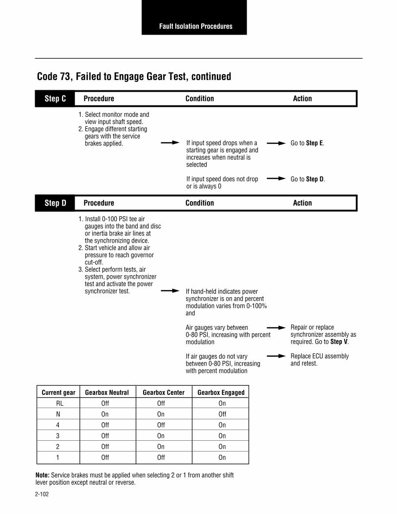
2-102
Fault Isolation Procedures
Code 73, Failed to Engage Gear Test, continued
1. Select monitor mode and view input shaft speed.2. Engage different starting gears with the service brakes applied. If input speed drops when a
starting gear is engaged andincreases when neutral isselected
If input speed does not dropor is always 0
Go to Step E.
Go to Step D.
Step C Condition ActionProcedure
1. Install 0-100 PSI tee air gauges into the band and disc or inertia brake air lines at the synchronizing device.2. Start vehicle and allow air pressure to reach governor cut-off.3. Select perform tests, air system, power synchronizer test and activate the power synchronizer test. If hand-held indicates power
synchronizer is on and percentmodulation varies from 0-100%and
Air gauges vary between 0-80 PSI, increasing with percent modulation
If air gauges do not varybetween 0-80 PSI, increasing with percent modulation
Repair or replace synchronizer assembly asrequired. Go to Step V.
Replace ECU assembly and retest.
Step D Condition ActionProcedure
Current gear Gearbox Neutral Gearbox Center Gearbox Engaged
RL Off Off On
N On On Off
4 Off Off On
3 Off On On
2 Off On On
1 Off Off On
Note: Service brakes must be applied when selecting 2 or 1 from another shift lever position except neutral or reverse.

2-103
Fault Isolation Procedures
1. Key off.2. Reconnect all connectors.3. Key on.4. Clear codes (see Clearing Fault Codes, page 1-3).5. Use Driving Technique
to attempt to reset the code (page 1-4).
6. Check for codes (see Retrieving Fault Codes, page 1-3). If no codes
If code 73 appears
If code other than 73 appears
Repairs complete.
Return to Step Ato find error in testing.
Go to Fault Isolation Procedure Index (page 1-8).
Step V Condition ActionProcedure
Code 73, Failed to Engage Gear Test, continued
1. Remove autoshifter and attempt to move shift blocks in and out of gear. If shift bar cover is OK
If shift bar cover is not OK
Replace autoshifter. Go to Step V.
Repair shift bar housing as required. Go to Step V.
Step F Condition ActionProcedure
1. Select monitor mode and view the following data:• Current gear• Gearbox center• Gearbox engage• Gearbox neutral
2. Place the shift lever in RL,N, 4, 3, 2 and 1 and observe the hand-held diagnostic display. Compare the display with the table. If signals correspond to table
If signals do not correspond to table
Replace autoshifter. Go to Step V.
Go to Step F.
Step E Condition ActionProcedure
Code 73

2-104
Fault Isolation Procedures
System Code 74Failed to Synchronize
Fault Description
This code indicates the transmission’s synchronizing systemis not performing as expected. During shifts between topgears, the transmission monitors input shaft acceleration anddeceleration, and determines whether performance issatisfactory. Code 74 sets if the performance is outside of thesatisfactory range.
Required Tools
• Basic Hand Tools
• Air Pressure Gauges (0-100 psi)
• CEEMAT Troubleshooting Guide
• Hand-Held Diagnostic Tool
• 0-300 PSI Hydraulic Gauges
• 0-100 PSI Hydraulic Gauge
Possible Causes
This code can be caused by any of the following conditions:
• Low air pressure
• Contaminated air supply
• Interrupt clutch is dragging
• Malfunctioning of the power synchronizer/inertia brake
• Malfunctioning synchronizer air valves
Likely Failure Locations
Powersynchronizer
Inertia brake
Air filter regulator
Torque converter
Band and disc brake solenoids

2-105
Fault Isolation Procedures
1. Key off.2. Connect hand-held diagnostic
tool.3. View the following data:
• Engine speed• Input speed• Output speed• Torque converter
4. Turn off PTO switch (if equipped).5. Start engine.6. When hand-held diagnostic tool display indicates the torque converter is open, quickly and fully press the throttle.7. Observe engine speed
and input speed readings. If engine speed and input speed separate
If engine speed and input speed always match
Step A
Code 74, Failed to Synchronize Test
Procedure Condition Action
Go to Step C.
Go to Step B.
Step B Procedure Condition Action
1. Install 0-300 PSI hydraulic gauges into diagnostic ports for:• Main• Interrupt clutch• Lockup/bypass clutch
2. Install a 0-100 PSI hydraulic gauge into the Lube diagnostic port.
3. Start engine. Allow air pressure to build to governor cut-off.
4. Turn PTO off (if equipped).5. On the hand-held diagnostic
tool, select Perform Tests.6. Select Hydraulic Tests. If pressures are in the ranges:
• Main = 225 to 255 PSI• Interrupt = 0 PSI• Lockup/bypass = 0 PSI• Lube = 15 to 35 PSI
If pressures are not in the ranges shown above
Replace the transmission. Go to Step V.
Replace the hydraulic valve assembly. Go to Step V.
Code 74
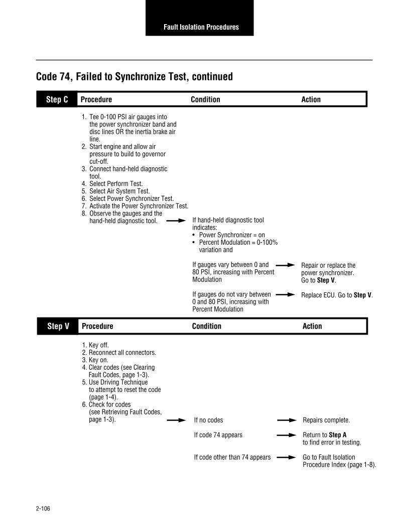
2-106
Fault Isolation Procedures
1. Tee 0-100 PSI air gauges into the power synchronizer band and disc lines OR the inertia brake air line.
2. Start engine and allow air pressure to build to governor cut-off.
3. Connect hand-held diagnostic tool.
4. Select Perform Test. 5. Select Air System Test. 6. Select Power Synchronizer Test. 7. Activate the Power Synchronizer Test. 8. Observe the gauges and the
hand-held diagnostic tool. If hand-held diagnostic tool indicates:• Power Synchronizer = on• Percent Modulation = 0-100%
variation and
If gauges vary between 0 and 80 PSI, increasing with Percent Modulation
If gauges do not vary between 0 and 80 PSI, increasing with Percent Modulation
Step C
Code 74, Failed to Synchronize Test, continued
Procedure Condition Action
Repair or replace the power synchronizer.Go to Step V.
Replace ECU. Go to Step V.
Step V Procedure Condition Action
1. Key off.2. Reconnect all connectors.3. Key on.4. Clear codes (see Clearing Fault Codes, page 1-3).5. Use Driving Technique
to attempt to reset the code (page 1-4).
6. Check for codes (see Retrieving Fault Codes, page 1-3). If no codes
If code 74 appears
If code other than 74 appears
Repairs complete.
Return to Step Ato find error in testing.
Go to Fault Isolation Procedure Index (page 1-8).

2-107
Fault Isolation Procedures
This Page left blank intentionally
Code 74

2-108
Fault Isolation Procedures
System Code 81Invalid Shift Lever at Start(Cable Only)
Fault Description
This code indicates the engine was able to start without theshift lever being positioned in Neutral.
Required Tools
• Basic Hand Tools
• CEEMAT Troubleshooting Guide
• Hand-Held Diagnostic Tool
Possible Causes
This code can be caused by any of the following conditions:
• Faulty lever cable
• Faulty shift lever
• Lever or shift cable out of adjustment
• Malfunctioning neutral start circuit
• Faulty ECU
Likely Failure Locations
ECU
Cable shift lever
(OEM supplied)
Shift cable
(OEM supplied)
Shift arm
ECU

2-109
Fault Isolation Procedures
1. Key on.2. Retrieve codes (page 1-3). If code 81 is active
If code 81 is inactive
Step A
Code 81, Invalid Shift Lever at Start Test (Cable Only)
Procedure Condition Action
Adjust shift lever.See procedure in Appendix.
Test complete
Code 81

2-110
Fault Isolation Procedures
Component Code 82Multiple Non-Adjacent Sensors(Cable Only)
Fault Description
This fault indicates and electrical problem inside the ECU. Theshift lever is sensing more than one lever position and thesensed positions are not adjacent to one another.
Required Tools
• Basic Hand Tools
• CEEMAT Troubleshooting Guide
• Hand-Held Diagnostic Tool
Possible Causes
This code is likely caused by a faulty shift lever.
Likely Failed Components
Shift arm
ECU

2-111
Fault Isolation Procedures
Code 82, Multiple Non-Adjacent Sensors Test (Cable Only)
1. Key on.2. Retrieve codes (page 1-3). If code 82 is active
If code 82 is inactive
Replace ECU.
Test complete.
Step A Condition ActionProcedure
Code 82

2-112
Fault Isolation Procedures
Shift arm
ECU
System Code 83Shift Lever Missing (Cable Only)
Fault Description
This fault indicates the shift lever is not sensing any leverpositions.
Required Tools
• Basic Hand Tools
• Hand-Held Diagnostic Tool
• CEEMAT Troubleshooting Guide
Possible Causes (Cable Only)
This code can be caused by any of the following conditions:
• Faulty lever cable
• Faulty shift lever
• Lever or shift cable out of adjustment
• Faulty ECU
Likely Failure Locations
Shift cable
(OEM supplied)
ECU
Cable shift lever
(OEM supplied)
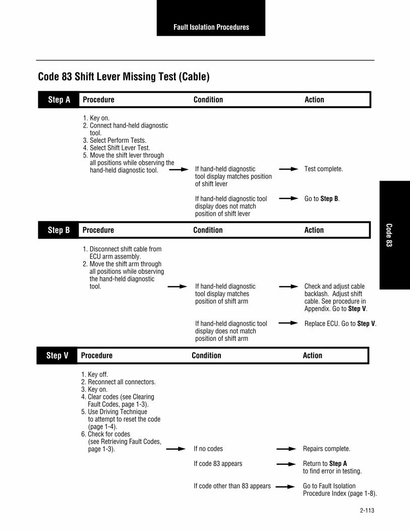
2-113
Fault Isolation Procedures
1. Key on.2. Connect hand-held diagnostic
tool.3. Select Perform Tests.4. Select Shift Lever Test.5. Move the shift lever through
all positions while observing the hand-held diagnostic tool. If hand-held diagnostic
tool display matches position of shift lever
If hand-held diagnostic tool display does not match position of shift lever
Step A
Code 83 Shift Lever Missing Test (Cable)
Procedure Condition Action
Test complete.
Go to Step B.
Step B Procedure Condition Action
1. Disconnect shift cable from ECU arm assembly.
2. Move the shift arm through all positions while observing the hand-held diagnostic tool. If hand-held diagnostic
tool display matches position of shift arm
If hand-held diagnostic tool display does not match position of shift arm
Check and adjust cable backlash. Adjust shift cable. See procedure in Appendix. Go to Step V.
Replace ECU. Go to Step V.
Step V Procedure Condition Action
1. Key off.2. Reconnect all connectors.3. Key on.4. Clear codes (see Clearing Fault Codes, page 1-3).5. Use Driving Technique
to attempt to reset the code (page 1-4).
6. Check for codes (see Retrieving Fault Codes, page 1-3). If no codes
If code 83 appears
If code other than 83 appears
Repairs complete.
Return to Step Ato find error in testing.
Go to Fault Isolation Procedure Index (page 1-8).
Code 83

2-114
Fault Isolation Procedures
Component Code 83Shift Lever Missing (Electronic Only)
Fault Description
This code indicates the shift lever is not sensing any leverpositions.
Required Tools
• Basic Hand Tools
• Hand-Held Diagnostic Tool
• CEEMAT Troubleshooting Guide
Possible Causes (Electronic Only)
This code is caused by a faulty shift lever.
Likely Failure Locations
Electronic shift lever (ESL)

2-115
Fault Isolation Procedures
Code 83 Shift Lever Missing Test (Electronic)
1. Key on.2. Connect hand-held diagnostic
tool.3. Select Perform Tests.4. Select Shift Lever Test.5. Move the shift lever through
all positions while observing the hand-held diagnostic tool. If hand-held diagnostic
tool display matches position of shift lever
If hand-held diagnostic tool display does not match position of shift lever
Step A Procedure Condition Action
Test complete.
Replace electronic shift lever. Go to Step V.
Step V Procedure Condition Action
1. Key off.2. Reconnect all connectors.3. Key on.4. Clear codes (see Clearing Fault Codes, page 1-3).5. Use Driving Technique
to attempt to reset the code (page 1-4).
6. Check for codes (see Retrieving Fault Codes, page 1-3). If no codes
If code 83 appears
If code other than 83 appears
Repairs complete.
Return to Step Ato find error in testing.
Go to Fault Isolation Procedure Index (page 1-8).
Code 83

2-116
Fault Isolation Procedures
This Page left blank intentionally

3-1
Symptom Isolation Procedures
1. Connect the hand-held diagnostic tool.
2. Start engine and allow to idle.3. Select vehicle interface and
monitor throttle percentage.4. Quickly and fully press throttle three times. If throttle percentage reads
0 to 100% as demand increases
If throttle percentage reads 100 to 0% as demand increases
If throttle position does not change
Go to Step B.
Repair reversed wires at vehicle interface harness connection to the throttle position sensor. Repeat this step.
Inspect throttle position sensor installation and linkage.Repair as required. See procedure in Appendix. Repeat this step.
Step A
Transmission Basic Inputs Pretest
Procedure Condition Action
1. Monitor brake switch on hand-held diagnostic tool.
2. Apply and release service brakes. If brake switch corresponds
with brake application
If brake switch does not correspond with service brake application
Go to Step E.
Go to Step C.
Step B Procedure Condition Action
1. Disconnect vehicle interface harness from transmission.
2. Measure voltage between vehicle interface harness pins B and E.
3. Apply and release service brakes. Observe the voltmeter. If voltage is within 1 volt
of battery voltage with service brake applied and
If voltage is less than 1 voltwith brakes released
If voltage does not change with service brake application
Replace ECU. Go to Step B.
Go to Step D.
Step C Procedure Condition Action
B A M
C P N L
D R V U
E S T J
K
F G H
VOLTS
V COM A
Transmission Basic Inputs Pretest

3-2
Symptom Isolation Procedures
A B
1. Locate service brake switch.2. Measure voltage between
each terminal and ground with the brakes applied and released. If there is voltage on both
terminals with service brake applied
If there is no voltage on either terminal
If there is voltage on both terminals when the service brake is not applied
If there is voltage on only one terminal with the service brake is applied
Repair or replace vehicle interface harness as necessary. Go to Step B.
Repair power supply to brake switch. Go to Step B.
Replace brake switch or repair system air pressure as required. Go to Step V.
Replace the service brake switch. Go to Step B.
Procedure Condition ActionStep D
Transmission Basic Inputs Pretest, continued
Note: If vehicle is not equipped with a countershaft PTO, go to Step H.1. Monitor PTO input on
hand-held diagnostic tool.2. Start engine.3. Engage and disengage
countershaft PTO. If PTO input display corresponds with PTO engagement
If PTO input display does not correspond with PTOengagement
Go to Step H.
Go to Step F.
Procedure Condition ActionStep E
1. Disconnect vehicle interface harness from transmission.
2. Measure voltage between vehicle interface harness pins D and B.
3. Engage and disengage the PTO. Observe the voltmeter. If voltage is within 1 volt
of battery voltage with PTOengaged and
Voltage is less than 1 volt with PTO disengaged
If voltage does not change with PTO application
Replace ECU. Go to Step E.
Go to Step G.
Procedure Condition ActionStep F
VOLTS
V COM A
GROUND
VOLTS
V COM A
GROUND
B A M
C P N L
D R V U
E S T J
K
F G H
VOLTS
V COM A

3-3
Symptom Isolation Procedures
A B
1. Locate countershaft PTO switch.2. Key on.3. Measure voltage between each
PTO switch terminal and ground with the PTO engaged and disengaged. If there is voltage on both
terminals with PTO engaged
If there is no voltage on either terminal
If there is voltage on both terminals when the PTO is not engaged
If there is voltage on only one terminal with the PTO engaged
Repair or replace vehicle interface harness as necessary. Go to Step E.
Repair power supply to PTO switch. Go to Step E.
Repair or replace PTO switch or PTO engagement system as required. Go to Step E.
Replace the PTO switch. Go to Step E.
Procedure Condition ActionStep G
Transmission Basic Inputs Pretest, continued
1. Determine the type of shift lever control. If the shift lever is electronic
If the shift lever is the cable type
Test complete.
Go to Step I.
Procedure Condition ActionStep H
1. On the hand-held diagnostic tool, select Shift Lever Test.
2. Move the shift lever through all shift lever positions. Observe the hand-held tool. If hand-held tool display
corresponds with shift lever positions
If hand-held tool display does not correspond with shift lever positions
Test complete.
Go to Step J.
Procedure Condition ActionStep I
VOLTS
V COM A
GROUND
VOLTS
V COM A
GROUND
Transmission Basic Inputs Pretest

3-4
Symptom Isolation Procedures
Transmission Basic Inputs Pretest, continued
1. Disconnect shift cable from the shift arm on the ECU.
2. Move the shift arm on the ECU through the shifter positions.Observe the hand-held tool. If hand-held tool display
corresponds with shift lever positions
If hand-held tool display does not correspond with shift lever positions
Check cable backlash and adjust as necessary. See procedure in Appendix.Go to Step I.
Replace ECU. Go to Step I.
Procedure Condition ActionStep J

3-5
Symptom Isolation Procedures
1. Start engine and allow it to idle. Adjust to idle
600 to 700 RPM if necessary.2. Connect hand-held
diagnostic tool.3. View engine speed.4. Fully press throttle. If the engine achieves
no-load rated speed
If the engine does not achieve no-load rated speed
Go to Step B.
Adjust engine for proper performance. Go to Step B.
Step A Procedure Condition Action
Engine Interface Pretest
1. Select Throttle Dip Test on the hand-held diagnostic tool.
2. Run engine at governed speed.3. Activate Throttle Dip Test
and observe engine RPM. If engine RPM drops 275 RPM per second or more for a total of 1000 RPM decrease
If engine RPM does not drop at least 275 RPM per second
Go to Step C.
Repair the throttle defuel system as necessary. Repeat this step.
Step B Procedure Condition Action
1. On the hand-held diagnostic tool, view engine speed.2. Load vehicle with a typical
load. Drive at full throttle. If engine reaches rated speed but transmission does not shift
If engine does not reach rated speed
If engine reaches rated speed and transmission shifts
Go to Step D.
Repair engine power problem. according to engine OEM. Repeat this step.
Test complete.
Step C Procedure Condition Action
Engine Interface Pretest

3-6
Symptom Isolation Procedures
1. Use the hand-held diagnostic tool to view the software part number. Record the number.
2. Contact an Eaton representative to confirm proper software. If the software is correct
If the software is not correct
Test complete.
The Eaton representative will help obtain the correct software.
Step D Procedure Condition Action
Engine Interface Pretest, continued

3-7
Symptom Isolation Procedures
1. Key on. Make sure the PTO switch if off (if equipped)
2. Connect hand-held diagnostic tool.
3. View the following data: • Engine speed • Input speed • Output speed • Torque converter4. When the torque converter
is Open, quickly and fullypress the throttle pedal open. If engine speed and input
speed separate
If engine speed and input speed match while engine speed increases
Go to Step C.
Go to Step B.
Step A
Shift Complaint Test
Procedure Condition Action
1. Install 0-300 PSI hydraulic gauges into diagnostic ports for:• Main• Interrupt clutch• Lockup/ bypass clutch
2. Install a 0-100 PSI hydraulic gauge into the lube diagnostic port.
3. Monitor gauges. If pressure readings are:• Main = 225 to 255 PSI• Interrupt = 0 PSI• Lockup/bypass = 0 PSI• Lube = 15 to 35 PSI
If pressure readings are not in the ranges shown above
Replace transmission.Go to Step V.
Replace the hydraulic valve assembly. Go to Step V.
Step B Procedure Condition Action
Shift Complaint Test

3-8
Symptom Isolation Procedures
1. Drive vehicle under load in 7th gear or above.
2. At a steady speed, observe the hand-held diagnostic tool and verify torque converter lockup. If engine speed and input
speed separate
If engine speed and input speed match while engine speed increases
Go to Step D.
Go to Step H.
Step C Procedure Condition Action
Shift Complaint Test, continued
1. Place transmission in neutral.2. Allow engine to idle at 600 to 700 RPM for a minimum of 2 minutes. Ensure transmission fluid temperature is 60 to 120° F.3. Check transmission fluid level. If fluid level is at or above
the COLD-FULL mark
If fluid level is below the COLD-ADD mark
Go to Step E.
Correct fluid level, check for leaks. Go to Step V.
Step D Procedure Condition Action
1. Install 0-300 PSI hydraulic gauges into diagnostic ports for:• Main• Interrupt clutch• Lockup/ bypass clutch
2. Install a 0-100 PSI hydraulic gauge into the lube diagnostic port.
3. Start engine and allow air pressure to build to governor cut-off.
4. Turn PTO off (if equipped).5. Connect hand-held tool and
select Perform Tests, Hydraulic Test.6. Allow engine to idle and observe
the pressure gauges. If pressure readings are:• Main = 225 to 255 PSI• Interrupt = 0 PSI• Lockup/bypass = 0 PSI• Lube = 15 to 35 PSI
If pressure readings are not in the ranges shownabove
Go to Step F.
Replace the hydraulic valve assembly. Go to Step V.
Step E Procedure Condition Action

3-9
Symptom Isolation Procedures
1. Connect the hand-held diagnostic tool. Select Perform Tests.
2. Select Interrupt Test. Activate the test and observe the gauges. If pressure readings are:
• Main = 225 to 255 PSI• Interrupt = ± 5 PSI of Main• Lockup/bypass = 0 PSI• Lube = 15 to 35 PSI
If pressure readings are not in the ranges shownabove
Go to Step G.
Replace the hydraulic valve assembly. Go to Step V.
Step F Procedure Condition Action
Shift Complaint Test, continued
1. Select Lockup Test. Activate the test and observe the gauges. If pressure readings are:
• Main = 225 to 255 PSI• Interrupt = 0 PSI• Lockup/bypass = ± 5 PSI
of Main• Lube = 15 to 35 PSI
If pressure readings are not in the ranges shownabove
Replace the transmission. Go to Step V.
Replace the hydraulic valve assembly. Go to Step V.
Step G Procedure Condition Action
Shift Complaint Test

3-10
Symptom Isolation Procedures
Shift Complaint Test, continued
1. Place transmission in neutral.2. Allow engine to idle at 600 to 700 RPM for a minimum of 2 minutes. Ensure transmission fluid temperature is 60 to 120° F.3. Check transmission fluid level. If fluid level is at or above
the COLD-FULL mark
If fluid level is below the COLD-ADD mark
Go to Step I.
Correct fluid level, check for leaks. Go to Step V.
Step H Procedure Condition Action
1. Install 0-300 PSI hydraulic gauges into diagnostic ports for:• Main• Interrupt clutch• Lockup/ bypass clutch
2. Install a 0-100 PSI hydraulic gauge into the lube diagnostic port.
3. Start engine and allow air pressure to build to governor cut-off.
4. Turn PTO off (if equipped).5. Connect hand-held tool and
select Perform Tests, Hydraulic Test.6. Allow engine to idle and observe
the pressure gauges. If pressure readings are:• Main = 225 to 255 PSI• Interrupt = 0 PSI• Lockup/bypass = 0 PSI• Lube = 15 to 35 PSI
If pressure readings are not in the ranges shownabove
Go to Step J.
Replace the hydraulic valve assembly. Go to Step V.
Step I Procedure Condition Action
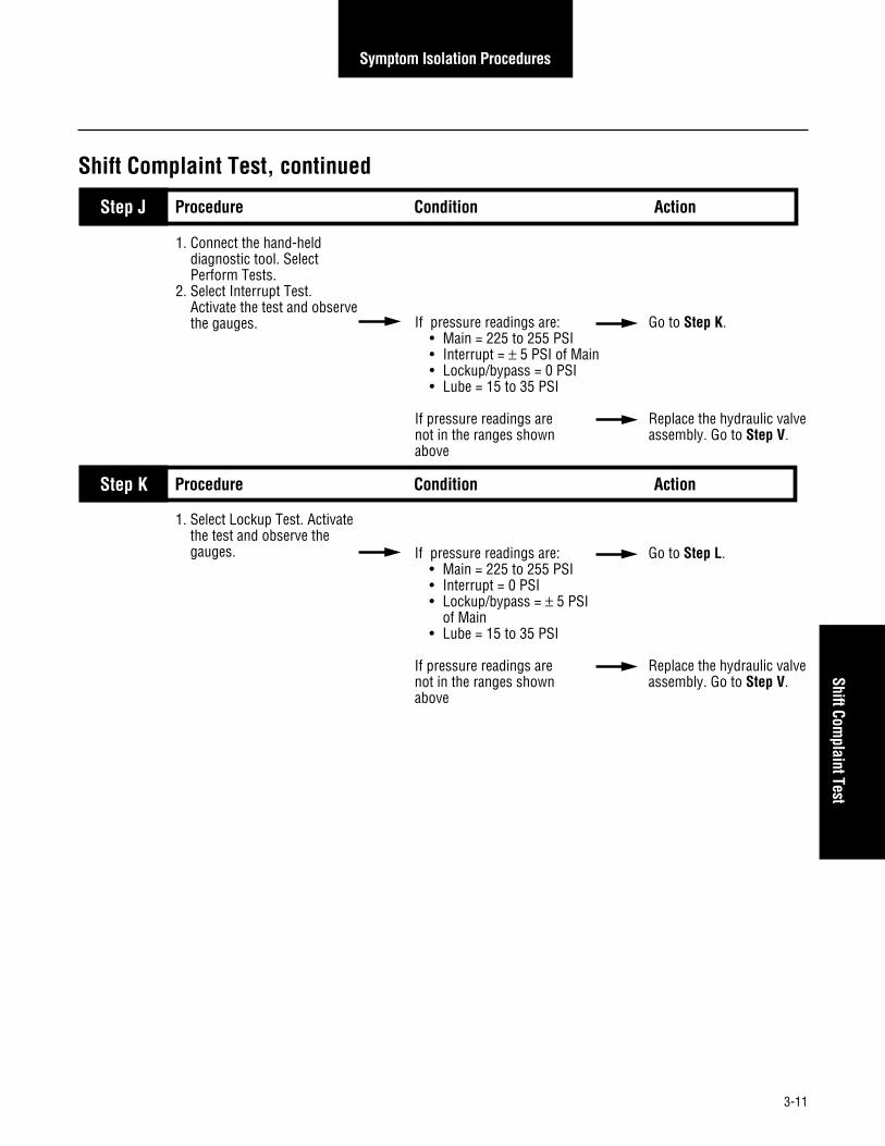
3-11
Symptom Isolation Procedures
1. Connect the hand-held diagnostic tool. Select Perform Tests.
2. Select Interrupt Test. Activate the test and observe the gauges. If pressure readings are:
• Main = 225 to 255 PSI• Interrupt = ± 5 PSI of Main• Lockup/bypass = 0 PSI• Lube = 15 to 35 PSI
If pressure readings are not in the ranges shownabove
Go to Step K.
Replace the hydraulic valve assembly. Go to Step V.
Step J Procedure Condition Action
Shift Complaint Test, continued
1. Select Lockup Test. Activate the test and observe the gauges. If pressure readings are:
• Main = 225 to 255 PSI• Interrupt = 0 PSI• Lockup/bypass = ± 5 PSI
of Main• Lube = 15 to 35 PSI
If pressure readings are not in the ranges shownabove
Go to Step L.
Replace the hydraulic valve assembly. Go to Step V.
Step K Procedure Condition Action
Shift Complaint Test

3-12
Symptom Isolation Procedures
1. Key off.2. Tee 0-100 PSI air gauges into the
power synchronizer disc and band lines, orTee a 0-100 PSI air gauge into the inertia brake line.
3. Start engine and allow air pressure to build to governor cutoff.4. Connect hand-held diagnostic tool.5. Select Perform Tests.6. Select Air System.7. Select Power Synchronizer Test.
Activate Power Synchronizer Test. If the hand-held diagnostic
tool display indicates:• Power synchronizer ON• 0-100% modulation
and
Air gauges vary between 0 and 80 PSI, increasing with % modulation
If air gauges do not vary between 0 and 80 PSI, increasing with % modulation
Go to Step M.
Replace ECU. Go to Step V.
Step L Procedure Condition Action
Shift Complaint Test, continued
1. Key off.2. Tee 0-100 PSI air gauges
into the range air lines. 3. Start engine and allow air pressure to build to governor cut- off.4. Connect hand-held diagnostic tool.5. Select Perform Tests.6. Select Air System. 7. Select and activate Range
System Test. If in HI range:• HI gauge = regulated
pressure• LO gauge = 0
and
If in LO range:• HI gauge = 0• LO gauge = regulated
pressure
If pressure readings are not in the ranges shown above
Contact Eaton representative for further assistance.
Replace the range valve on side of ECU. Go to Step V.If the problem persists, replace the ECU.
Step M Procedure Condition Action

3-13
Symptom Isolation Procedures
1. Key off.2. Reconnect all connectors.3. Key on.4. Drive the vehicle to determine
whether shift complaint has been repaired. If the shift complaint was
repaired
If the shift complaint was not repaired
Test complete.
Return to Step A to find error in testing.
Step V Procedure Condition Action
Shift Complaint Test, continued
Shift Complaint Test

3-14
Symptom Isolation Procedures
1. Check transmission temperature gauge, sending unit and associated components for proper operation. If the temperature gauge
functions properly
If the temperature gauge does not function properly
Go to Step B.
Repair the temperature gauge circuit as necessary.Go to Step V.
Step A
High Operating Temperature TestNormal operating temperature is 275˚ F (130˚ C).
Procedure Condition Action
1. Check transmission for proper lubricant type (specified in the Driver Instructions). If fluid is OK
If the fluid is not correct
Go to Step C.
Fully drain transmission and transmission cooling system.Refill with recommended fluid.Go to Step V.
Step B Procedure Condition Action
1. Check cooling system for proper installation and capacity.
2. Check for any blockage or restrictions in the system. If transmission cooling
system is OK
If transmission cooling system is not OK
Go to Step D.
Repair cooling system as necessary. Go to Step V.
Step C Procedure Condition Action
1. Drive vehicle under load in 7th gear or above.
2. At a steady speed, observe the hand-held diagnostic to verify torque converter lockup.
3. Monitor engine speed andinput speed on the hand-held diagnostic tool. If engine speed and input
speed separate
If engine speed and input speed match while engine speed increases
Go to Step E.
Contact an Eaton Representative for further information.
Step D Procedure Condition Action

3-15
Symptom Isolation Procedures
High Operating Temperature Test, continued
1. Install 0-300 PSI hydraulic gauges into diagnostic ports for:• Main• Interrupt clutch• Lockup/ bypass clutch
2. Install a 0-100 PSI hydraulic gauge into the lube diagnostic port.
3. Start engine and allow air pressure to build to governor cut-off.
4. Turn PTO off (if equipped).5. Connect the hand-held diagnostic
tool. Select Perform Tests.6. Select Hydraulic Test.7. Observe the gauges.
Step F Procedure Condition Action
If pressure readings are:• Main = 225 to 255 PSI• Interrupt = 0 PSI• Lockup/bypass = 0 PSI• Lube = 15 to 35 PSI
If pressure readings are not in the ranges shown above
Go to Step G.
Replace hydraulic valve assembly. Go to Step V.
1. Check oil level.2. Key on.3. Place transmission in neutral.4. Allow engine to idle at 600 to 700 RPM for a minimum of 2 minutes. Ensure transmission fluid temperature is 60 to 120° F.5. Check transmission fluid level. If fluid level is at or above
the COLD-FULL mark
If fluid level is below the COLD-ADD mark
Go to Step B.
Correct fluid level, check for leaks. Go to Step V.
Step E Procedure Condition Action
High Operating Temperature Test

3-16
Symptom Isolation Procedures
1. Select interrupt test and activate test while monitoring the pressure gauges. If pressures match the
specifications:• Main: 225-255 PSI• Interrupt: ±5 of main• Lockup: 0 PSI• Lube: 15-35 PSI
If pressures do not matchspecifications
Go to Step H.
Replace hydraulic valve assembly. Go to Step V.
Step G Procedure Condition Action
1. Select lockup test and activate test while monitoring the pressure gauges. If pressures match the
specifications:• Main: 225-255 PSI• Interrupt: 0 PSI• Lockup: ±5 of main• Lube: 15-35 PSI
If pressures do not matchspecifications
Contact Eaton TruckComponents for further assistance.
Replace hydraulic valve assembly. Go to Step V.
Step H Procedure Condition Action
High Operating Temperature Test, continued
1. Operate vehicle and that transmission does not rise above 275˚ F (130˚ C) when operating under load. If transmission temperature
does not rise above 275˚
If transmission temperature rises above 275˚
Go to Step G.
Test complete.Go to Step A.
Step V Procedure Condition Action

3-17
Symptom Isolation Procedures
1. Key on.2. Connect hand-held diagnostic
tool. If hand-held diagnostic tool powers up
If hand-held diagnostic tool does not power up
Go to Step B.
Go to Step G.
Step A Procedure Condition Action
Hand-Held Diagnostic Tool Failed to Operate Test
1.On the hand-held diagnostic tool, select CEEMAT product. If the display reads “Failed
to Communicate”
If the display does not read “Failed to Communicate”
Go to Step C.
Replace the hand-held diagnostic tool. Go to Step V.
Step B Procedure Condition Action
1. Disconnect vehicle interface harness from ECU.
2. Measure resistance from vehicle interface harness pin N and diagnostic connector pin A. If resistance is 0 to .3 ohms
If resistance is outside of range
Go to Step D.
Repair or replace vehicleinterface harness. Repeat this step.
Step C Procedure Condition Action
1. Measure resistance between diagnostic connector pin A and ground. If resistance is greater than
10K ohms or infinite
If resistance is less than 10K ohms
Go to Step E.
Repair or replace vehicle interface harness. Go to Step V.
Step D Procedure Condition Action
OHMS
V COM A
F
E
D
A
B
C
B A M
C P N L
D R V U
E S T J
K
F G H
OHMS
V COM A
F
E
D
A
B
C
GROUND
Hand-Held Diagnostic ToolFailed to Operate Test

3-18
Symptom Isolation Procedures
1. Measure resistance between vehicle interface harness pin M and diagnostic connector pin B. If resistance is 0 to .3 ohms
If resistance is outside of range
Go to Step F.
Repair or replace vehicle interface harness. Go to Step V.
Step E Procedure Condition Action
OHMS
V COM A
F
E
D
A
B
C
B A M
C P N L
D R V U
E S T J
K
F G H
Hand-Held Diagnostic Tool Failed to Operate Test, continued
1. Measure resistance between diagnostic connector pin B and ground. If resistance is greater than
10K ohms or infinite
If resistance is less than 10K ohms
Replace ECU. Go to Step V.
Repair or replace vehicle interface harness. Go to Step V.
Step F Condition Action
OHMS
V COM A
F
E
D
A
B
C
GROUND
1. Disconnect hand-held diagnostic tool from vehicle connector.
2. Measure voltage between diagnostic connector pin C and ground. If voltage is within 1 volt
of battery voltage
If voltage is outside of range
Go to Step H.
Repair battery power line to vehicle diagnostic connector. Go to Step V.
Step G Procedure Condition Action
VOLTS
V COM A
F
E
D
A
B
C
GROUND
Procedure

3-19
Symptom Isolation Procedures
1. Key off.2. Disconnect the positive (+)
battery cable.3. Measure resistance between
diagnostic connector pin E and battery negative (–) terminal.
If resistance is 0 to .3 ohms
If resistance is outside ofrange
Repair the hand-held diagnostic tool harness.Go to Step V.If the problem persists, replace the hand-held diagnostic tool.
Repair ground wire to vehicle diagnostic connector harness. Go to Step V.
Step H Procedure Condition Action
OHMS
V COM A
F
E
D
A
B
C
+–
1. Key on.2. Connect hand-held
diagnostic tool. If hand-held diagnostic tool powers up normally
If hand-held diagnostic tool does not power up
Test complete.
Go to Step B.
Step V Procedure Condition Action
Hand-Held Diagnostic Tool Failed to Operate Test, continued
Hand-Held Diagnostic ToolFailed to Operate Test

3-20
Symptom Isolation Procedures
1. Key on.2. Shift transmission to any
position other than neutral.3. Locate 24-way connector
on the shift lever. Do not disconnect the connector.
4. Measure voltage between 24-way connector pin A3 and ground.
Note: Do not short pins in connector while performing measurement. If voltage is within 1 volt of
battery voltage
If voltage is outside of range
Go to Step C.
Go to Step B.
Step A Procedure Condition Action
Shift Lever In Gear Signal Test
1. Disconnect the 24-way connector from the shift lever.
2. Measure resistance between pin A3 and ground. If resistance is greater than
30 ohms
If resistance is outside of range
Replace the shift lever. Go to Step V.
Repair conflict in the circuit driven by the shift lever output. See OEM manuals for procedures. Go to Step V.
Step B Procedure Condition Action
1. Shift transmission to neutral.2. Measure voltage between
pin A3 and ground.Note: Do not short pins in connector while performing measurement. If voltage is 0 to 0.5 volts
If voltage is outside of range
Shift lever is OK. Repair in-gear output circuit. See OEM manuals for procedures. Go to Step V.
Go to Step D.
Step C Procedure Condition Action
1 2 3 4 5 6 7 8 9 10 11 12A
B
A
B
OHMS
V COM A
GROUND
12 11 2 1B B
12 11 10 9 8 7 6 5 4 3 2 1
AAVOLTS
V COM A
GROUND
12 11 2 1B B
12 11 10 9 8 7 6 5 4 3 2 1
AAVOLTS
V COM A
GROUND

3-21
Symptom Isolation Procedures
1. Disconnect the 24-way connector from the shift lever.
2. Measure resistance between pin A3 and ground. If voltage is 0 to 0.5 volts
If voltage is outside of range
Replace shift lever. Go to Step V.
Repair constant power to OEM function that uses the in-gear signal. See OEM manuals for procedures.Go to Step V.
Step D Procedure Condition Action
1. Key off.2. Reconnect all connectors.3. Key on.4. Operate vehicle to determine
whether the shift lever in-gear signal is operating correctly. If the function operates
correctly
If the function does not operate correctly
Repairs are complete.
Return to Step A to find error in testing.
Step V Procedure Condition Action
Shift Lever In Gear Signal Test, continued
1 2 3 4 5 6 7 8 9 10 11 12A
B
A
B
VOLTS
V COM A
GROUND
Shift Lever In Gear Signal Test

3-22
Symptom Isolation Procedures
A B
1. Key on.2. Connect hand-held diagnostic
tool.3. Put transmission in neutral
and monitor the following information:• Current gear• Gearbox center• Gearbox neutral • Gearbox engage If specifications are:
• Current gear: neutral• Gearbox center: on• Gearbox neutral: on• Gearbox engage: off
If specifications do not matchthose above
Step A
Neutral Output Test
Procedure Condition Action
Go to Step B.
Perform isolation procedure for Code 71 (page 2-92).
Step B Procedure Condition Action
1. Locate connection from CEEMAT neutral output and vehicle function.2. Measure voltage between vehicle connection and ground. If voltage is
Engaged=0 voltsNeutral=1 volt within battery voltage
If voltage does not match conditions above
Vehicle equipment is not responding properly to transmission neutraloutput. Repair as required.
Go to Step C.
VOLTS
V COM A
GROUND

3-23
Symptom Isolation Procedures
Neutral Output Test, continued
Step C Procedure Condition Action
1. Key off. 2. Disconnect vehicle interface
harness from ECU.3. Measure resistance between
vehicle interface harness pin V and vehicle connection. If resistance is 0 to .3 ohms
If the resistance is outside ofrange
Replace ECU. Go to Step V.
Repair vehicle interface harness or wiring to vehicle connection. Go to Step V.
A B
B A M
C P N L
D R V U
E S T J
K
F G H
VOLTS
V COM A
1. Key off.2. Reconnect all connectors.3. Key on.4. Operate vehicle to determine
whether the shift lever in-gear signal is operating correctly. If the function operates
correctly
If the function does not operate correctly
Repairs are complete.
Return to Step A to find error in testing.
Step V Procedure Condition Action
Neutral Output Test

3-24
Symptom Isolation Procedures
1. Key on.2. Connect hand-held diagnostic
tool.3. View the following data:
• Current gear • Torque converter
4. Move shift lever into drive.5. Engage and disengage split
shaft pump while monitoring hand-held diagnostic tool. If the following readings are
displayed:With pump on:• Current gear = 8th• Torque converter = LOCK
With pump off:• Current gear = 3rd or 4th• Torque converter = ENGD
If display does not match conditions above
Step A
Splitshaft PTO Switch Test
Procedure Condition Action
Repair or replace split shaft pump. Go to Step V.
Go to Step B.
Step B Procedure Condition Action
1. Retrieve hand-heldsoftware part number.
2. Contact Eaton representativeto verify that ECU is programmed for quick to neutral If ECU is not programmed for
quick to neutral
If ECU is not programmed correctly
Replace ECU and retest.
Contact Eaton representative for assistance in correcting ECU.

3-25
Symptom Isolation Procedures
Splitshaft PTO Switch Test, continued
Step V Procedure Condition Action
1. View the following data on the hand-held diagnostic tool:• Current gear• Torque converter
2. Engage and disengage split shaft pump while monitoring hand-held diagnostic tool. If the following readings
are displayedWith pump on:• Current gear = 8th• Torque converter = lock
With pump off:• Current gear = N• Torque converter = open
If display does not match conditions above
Test complete.
Go to Step C.
Step C Procedure Condition Action
1. Disconnect vehicle interface harness from ECU.
2. Move shift lever into neutral3. Measure voltage between
vehicle interface harness pins R and B.
4. Observe voltmeter while switching split shaft pump on and off. If the following voltage is
observed:• Pump on = 1 volt of battery
voltage• Pump off = 0 volts
If display does not match conditions above
Replace ECU. Go to Step C.
Repair or replace vehicleinterface harness, split shaft PTO switch orswitch power supply asrequired. Go to Step V.
B A M
C P N L
D R V U
E S T J
K
F G H
VOLTS
V COM A
Splitshaft PTO Switch Test

3-26
Symptom Isolation Procedures
1. Key off.2. Disconnect vehicle interface
harness from transmission.3. Key on.4. Measure voltage between
vehicle interface harness pins R and B while engaging and disengaging switches. If voltage is:
• Switch on = within 1 volt of battery voltage
• Switch off = 0 volts
If voltage is outside of range
Step A
Quick to Neutral Test
Procedure Condition Action
Go to Step B.
Repair quick to neutral signal input to CEEMATaccording to OEM serviceinformation. Go to Step V.
Step B Procedure Condition Action
1. Retrieve hand-heldsoftware part number.
2. Contact Eaton representativeto verify that ECU is programmed for quick to neutral If ECU is not programmed for
quick to neutral
If ECU is not programmed correctly
Replace ECU and retest.
Contact Eaton representative for assistance in correcting ECU.
B A M
C P N L
D R V U
E S T J
K
F G H
VOLTS
V COM A
Step V Procedure Condition Action
1. Operate vehicle and verify normal quick to neutral operation. If normal operation
If not operating normally
Test complete.
Go to Step A.
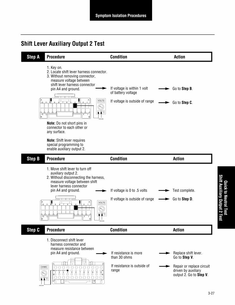
3-27
Symptom Isolation Procedures
1. Key on.2. Locate shift lever harness connector.3. Without removing connector, measure voltage between shift lever harness connector pin A4 and ground.
Note: Do not short pins in connector to each other or any surface.
Note: Shift lever requires special programming to enable auxiliary output 2.
If voltage is within 1 volt of battery voltage
If voltage is outside of range
Go to Step B.
Go to Step C.
Step A
If voltage is 0 to .5 volts
If voltage is outside of range
Test complete.
Go to Step D.
1. Move shift lever to turn off auxiliary output 2.2. Without disconnecting the harness, measure voltage between shift lever harness connector pin A4 and ground.
Shift Lever Auxiliary Output 2 Test
Procedure Condition Action
Step B Procedure Condition Action
If resistance is more than 30 ohms
If resistance is outside of range
Replace shift lever. Go to Step V.
Repair or replace circuit driven by auxiliary output 2. Go to Step V.
1. Disconnect shift lever harness connector and measure resistance between pin A4 and ground.
Step C Procedure Condition Action
VOLTS
V COM A
GROUND
12 11 2 1B B
12 11 10 9 8 7 6 5 4 3 2 1
AA
VOLTS
V COM A
GROUND
12 11 2 1B B
12 11 10 9 8 7 6 5 4 3 2 1
AA
OHMS
V COM A
GROUND
1 2 3 4 5 6 7 8 9 10 11 12A
B
A
B
Quick to Neutral TestShift Auxiliary Output 2 Test

3-28
Symptom Isolation Procedures
Shift Lever Auxiliary Output 2 Test, continued
Step V Procedure Condition Action
1. Operate shift lever.2. Verify that output function is operating normally. If operating normally
If not operating normally
Test complete.
Go to Step A.
If voltage is within .5 volts of battery voltage
If voltage is outside of range
Replace shift lever. Go to Step V.
Repair/replace harness. Go to Step V.
1. Disconnect shift lever harness connector and measure voltage between pin A4 and ground.
Step D Procedure Condition Action
VOLTS
V COM A
GROUND
1 2 3 4 5 6 7 8 9 10 11 12A
B
A
B

3-29
Symptom Isolation Procedures
1. Key off.2. Disconnect harness from electronic shift lever.3. Activate parking brake.4. Measure resistance between shift lever harness pin B10 and ground. If resistance is 0 to .3 ohms
If resistance is outside of range
Go to Step B.
Repair line between parking brake switch and shift lever. Go to Step V.
Step A
If resistance is more than 10K ohms or infinite
If resistance is less than 10K ohms
Replace shift lever. Go to Step V.
Repair line between parking brake switch and shift lever. Go to Step V.
1. Deactivate function which connects to transmission input.2. Measure resistance between shift lever harness pin B10 and ground.Note: Insure truck will not roll.
Shift Lever Auto Neutral Input Test
Procedure Condition Action
Step B Procedure Condition Action
Step V Procedure Condition Action
1. Connect shift lever harness to shift lever.2. Check for proper function. If harness operates properly
If harness does not operate properly
Clear transmission fault codes. Test complete.
Replace shift lever harness. Repeat this step.
OHMS
V COM A
GROUND
1 2 3 4 5 6 7 8 9 10 11 12A
B
A
B
OHMS
V COM
A
GROUND
1 2 3 4 5 6 7 8 9 10 11 12A
B
A
B
Shift Lever Auto Neutral Input Test

3-30
Symptom Isolation Procedures
1. Key off.2. Disconnect shift lever harness.3. Key on.4. Measure voltage between shift lever harness connector pins B4 and B12 while adjusting dash light brightness. If voltage varies between 0
and battery voltage
If voltage does not vary between 0 and battery voltage
Go to Step B.
Repair shifter harness wiring.
Note: Vehicle may be wired for constant voltage when lights are on. Voltage will not vary.
Step A
Shift Lever Back Light Test
Procedure Condition Action
If backlight works correctly
If backlight does not work correctly
Test complete.
Replace shift lever. Go to Step V.
1. Replace light bulb in shift lever and test backlight.
Step V Procedure Condition Action
Step C Procedure Condition Action
If voltage is within 1 volt of battery voltage
If voltage is outside of range
Go to Step C.
Repair short to power or miswired vehicle harness. Go to Step V.
1. Turn lights off. 2. Measure voltage between shift lever harness connector pins B4 and B12.
Step B Procedure Condition Action
1. Turn lights on.2. Vary dash light brightness while observing shift lever. If backlight operates normally
(may vary with dash lights)
If backlight does not operate normally
Test complete.
Go to Step A.
VOLTS
V COM A
1 2 3 4 5 6 7 8 9 10 11 12A
B
A
B
VOLTS
V COM A
1 2 3 4 5 6 7 8 9 10 11 12A
B
A
B

3-31
Symptom Isolation Procedures
Note: Reverse indicator relayinstallation may vary. Verify theproper wiring through OEM wiring schematic and CEEMAT installation guide.1. Key off.2. Disconnect reverse relay harness connector.3. Key on.4. While moving shift lever through non-reverse positions, measure voltage between reverse relay harness connector pins 1 and 2. If voltage is 0 to .5 volts
If voltage is outside of range
Go to Step B.
Replace shift lever. Go to Step V.
Step A
voltage is 0 to .5 volts
If voltage is outside of range
Go to Step C.
Go to Step D.
1. Place shift lever in reverse.2. Measure voltage between reverse relay harness connector pins 1 and 2.
Reverse Relay Indicator Test
Procedure Condition Action
Step C Procedure Condition Action
Step B Procedure Condition Action
1. Measure resistance between reverse relay pins:
• 1 and 2• 3 and 5 If resistance is:
• Relay pins 1 and 2 =40 to 90 ohms
• Relay pins 3 and 5 =10K ohms or infinite
If resistance is outside of range
Go to Step E.
Replace reverse indicator relay. Go to Step V.
1 4 2
3
5
VOLTS
V COM A
1 4 2
3
5
VOLTS
V COM A
2 4 1
3
5
OHMS
V COM A
2 4 1
3
5
OHMS
V COM A
Shift Lever Back Light TestReverse Relay Indicator Test

3-32
Symptom Isolation Procedures
1 2 3 4 5 6 7 8 9 10 11 12A
B
A
B
1. Disconnect harness connector from shift lever.2. Measure resistance between reverse relay connector pin 1 and shift lever harness connector pin B6.
3. Measure resistance between reverse relay connector pins 2 and shift lever pin B5. If resistance is 0 to .3 ohms
If resistance is outside ofrange
Replace shift lever. Go to Step V.
Repair or replace shifter harness. Go to Step V.
Step D
Reverse Relay Indicator Test, continued
Procedure Condition Action
If one pin has voltage within 1.0 volt of battery voltage
If voltage is outside of range
Go to Step F.
Ignition power not getting to reverse indicator relay, repair harness. Go to Step V.
1. Key on.2. Measure voltage between reverse relay harness connector pin:
• 3 and ground• 5 and ground
Step E Procedure Condition Action
2 4 1
3
5
OHMS
V COM A
2 4 1
3
5
OHMS
V COM A
1 4 2
3
5
VOLTS
V COM A
GROUND
1 4 2
3
5
VOLTS
V COM A
GROUND
1 2 3 4 5 6 7 8 9 10 11 12A
B
A
B

3-33
Symptom Isolation Procedures
Reverse Relay Indicator Test, continued
Step F Procedure Condition Action
1. Place jumper wire between relay harness connector pins 3 and 5. If reverse indicators active
If reverse indicators do not activate
Replace reverse relay. Go to Step V.
Problem exists in reverseindicator circuit beyond shift lever relay. Repair wiring. Go to Step V.
Step V Procedure Condition Action
1. Operate shift lever to verify that reverse indicators are operating normally. If indicators are operating
normally
If indicators are not operating normally
Test complete.
Go to Step A.
1 4 2
3
5
Reverse Relay Indicator Test

3-34
Symptom Isolation Procedures
Note: Start enable relay installationmay vary. Review proper wiringin OEM schematics and CEEMAT installation guide.1. Key off.2. Disconnect neutral relay harness connector from relay.3. Key on.4. While selecting all non-neutral positions, measure voltage between relay harness pin 1 and 2. If voltage is 0 to .5 volts
If voltage is outside of range
Go to Step B.
Replace shift lever.
Step A
If voltage is within 1 volt of battery voltage
If voltage is outside of range
Go to Step C.
Go to Step E.
1. Place shift lever(s) in neutral.2. Measure voltage between harness pins 1 and 2.
Start Enable Relay Test
Procedure Condition Action
Step C Procedure Condition Action
Step B Procedure Condition Action
1. Measure resistance between relay pins:
• 1 and 2• 3 and 5. If resistance is:
• Pins 1 and 2 = 40 to 90 ohms• Relay pins 3 and 5 = 10K ohms
or infinite
If resistance is outside of range
Go to Step D.
Replace start enable relay. Go to Step A.
1 4 2
3
5
VOLTS
V COM A
1 4 2
3
5
VOLTS
V COM A
2 4 1
3
5
OHMS
V COM A
2 4 1
3
5
OHMS
V COM A

3-35
Symptom Isolation Procedures
1. Disconnect harness from shift lever.2. Measure resistance between relay harness pin 1 and shift lever harness pin A1.3. Measure resistance between relay harness pin 2 and shift lever harness pin B2. If resistance is 0 to .3 ohms
If resistance is outside of range
Replace shifter harness. Go to Step V.
Replace or replace shift lever harness. Go to Step V.
Step E
Start Enable Relay Test, continued
Procedure Condition Action
Step D Procedure Condition Action
1. While engaging starter switch, measure voltage between start enable relay harness pin 5 and ground and relay harness pin 3 and ground. If one pin has voltage within
1 volt of battery voltage
If voltage is outside of range
Go to Step F.
Go to Step G.1 4 2
3
5
VOLTS
V COM A
GROUND
1 4 2
3
5
OHMS
V COM A
1 4 2
3
5
OHMS
V COM A
1 2 3 4 5 6 7 8 9 10 11 12A
B
A
B
1 2 3 4 5 6 7 8 9 10 11 12A
B
A
B
1 4 2
3
5
VOLTS
V COM A
GROUND
Start Enable Relay Test

3-36
Symptom Isolation Procedures
Start Enable Relay Test, continued
Step F Procedure Condition Action
1. Place jumper wire between relay harness connector pins 3 and 5 and engage starter. If starter engages properly
If starter does not engageat all
Replace start enable relay.Go to Step V.
Repair starter line, systemwiring or starter as required. Go to Step V.
Step G Procedure Condition Action
1. Check to see if the vehicle has two shift levers. If two shift levers
If only one shift lever
Go to Step H.
Repair OEM starter wiring between starter switch and relay. Go to Step V.
Step H Procedure Condition Action
1. Put shift levers in neutral.2. Reconnect first shift lever.3. Disconnect neutral relay harness from second shifter relay.4. Key on.5. Measure voltage between relay harness connector pins 1 and 2. If voltage is within 1 volt of
battery voltage
If voltage is outside of range
Go to Step J.
Go to Step I.
1 4 2
3
5
1 4 2
3
5
VOLTS
V COM A

3-37
Symptom Isolation Procedures
Start Enable Relay Test, continued
Step J Procedure Condition Action
1. Measure resistance between relay pins 1 and 2. If resistance equals
40 to 90 ohms
If resistance does not equal 40 to 90 ohms
Go to Step K.
Replace start enable relay. Go to Step V.
Step I Procedure Condition Action
1. Disconnect harness from second shift lever.2. Measure resistance between relay connector pin 1 and shift lever harness connector pin A1.3. Measure resistance between relay connector pin 2 and shift lever harness connector pin B2. If resistance is 0 to .3 ohms
If resistance is outside of range
Replace shift lever.Go to Step V.
Repair or replace shifter harness. Go to Step V.
2 4 1
3
5
OHMS
V COM A
1 4 2
3
5
OHMS
V COM A
1 2 3 4 5 6 7 8 9 10 11 12A
B
A
B
1 4 2
3
5
OHMS
V COM A
1 2 3 4 5 6 7 8 9 10 11 12A
B
A
B
Start Enable Relay Test

3-38
Symptom Isolation Procedures
Start Enable Relay Test, continued
Step L Procedure Condition Action
1. While engaging starter switch, measure voltage between relay harness connector pin:
• 5 and ground • 3 and ground. If one pin has voltage within
1 volt of battery voltage
If voltage is outside of range
Go to Step M.
Repair starter systems wiring or starter as required.Go to Step V.
Step M Procedure Condition Action
1. Place jumper wire between relay harness connector pins 3 and 5 and engage starter. If starter engages properly
If starter does not engage at all
If starter engages intermittentlyor inadvertently
Replace start enable relayand test.
Repair starter systems wiring or starter as required.Go to Step V.
Go to Step N.
1 4 2
3
5
VOLTS
V COM A
GROUND
1 4 2
3
5
1 4 2
3
5
VOLTS
V COM A
GROUND
Step K Procedure Condition Action
1. Measure resistance between relay harness connector pins 3 and 5.
If resistance is more than10K ohms or infinite
If resistance is less than 10K ohms
Replace start enable relay.Go to Step L.
Go to Step V.1 4 2
3
5
OHMS
V COM A

3-39
Symptom Isolation Procedures
Step O Procedure Condition Action
1. Remove 24-pin connectorfrom shift lever.
2. Remove start enable relayfrom harness.
3. Measure resistance betweenrelay harness connector pin 5and shift lever harness connectorpin A2. If resistance is 0 to .3 ohms
If resistance is outside of range
Replace shift lever.Go to Step V.
Repair harness. Go to Step V.
Start Enable Relay Test, continued
Step N Procedure Condition Action
1. Insure start enable solenoidcircuit is wired according to the wiring diagram. Refer to Appendix. If wiring is correct
If wiring is not correct
Go to Step O.
Repair wiring. Go to Step V.
Step V Procedure Condition Action
1. Place shift lever in neutral and engage starter.2. Place shift lever in non-neutral position and engage starter. If starter engages in neutral
and does not engage in non-neutral position
If starter does not engage in neutral or engages in non-neutral position
Test complete.
Go to Step A.
1 4 2
3
5
OHMS
V COM A
1 2 3 4 5 6 7 8 9 10 11 12A
B
A
B
Start Enable Relay Test

3-40
Symptom Isolation Procedures
1. Make sure starter solenoid circuit is wired as shown in figures 1 and 2. If wiring is correct
If wiring is not correct
Go to Step B.
Repair wiring conflict. Go to Step V.
Step A
Start Enable Relay Latch Test
Procedure Condition Action
+ BATT
Electronicshiftleverconnector
Startersolenoid
3 5
ACCOFF
Ignition
Keyswitch
Startenablerelay
Startpushbutton
A1A2
B2
1
2
+ BATT
Shiftleverconnector
Startersolenoid
3 5
ACCOFF
Ignition
Keyswitch
Startenablerelay
A1A2
B2
1
2
Figure 1:Starter solenoid crcuit with key switch.
Note: Dual station starter solenoid circuit in Appendix.
Figure 2:Starter solenoid circuit with push button start.

3-41
Symptom Isolation Procedures
If resistance is less than 0.3 ohms
If resistance is not less than 0.3 ohms
Replace shift lever. Go to Step V.
Repair start enable relay latch. Go to Step V.
1. Key off.2. Disconnect the shift lever harness connector.3. Disconnect start enable relay from harness.4. Measure resistance between start enable relay harness connector pin 5 and shift lever harness connector pin A2.
Step V Procedure Condition Action
Step B Procedure Condition Action
1. Start engine. If operation is normal
If operation is not normal
Test complete.
Go to Step A.
1 4 2
3
5
OHMS
V COM A
1 2 3 4 5 6 7 8 9 10 11 12A
B
A
B
Start Enable Relay Latch Test, continued
Start Enable Relay Latch Test

3-42
Symptom Isolation Procedures
1. Key off.2. Measure battery voltage at the battery terminals. If voltage is 11 to 13 volts
If voltage is not 11 to 13 volts (above or below)
Go to Step B.
Repair or replace battery and charging system as required. Repeat this step..
Step A
If voltage is within 1 volt of battery voltage
If voltage is outside of range
Go to Step C.
Repair or replace vehicle interface harness, circuit breaker or battery circuit as required. Repeat this step.
Shift Lever Voltage Test (Driver Lever)
Procedure Condition Action
1. Key off.2. Disconnect harness from shift lever (driver lever).3. Measure voltage between shift lever harness pin A5 and battery negative (–) terminal.
Step B Procedure Condition Action
Step C Procedure Condition Action
1. Key on.2. Measure voltage between
shift lever harness pin A7 and battery negative (–) terminal. If voltage is within 1 volt of
battery voltage
If voltage is outside of range
Go to Step D.
Repair or replace vehicle interface harness, circuit breaker or ignition circuit as required. Repeat this step.
VOLTS
V COM A
+–
1 2 3 4 5 6 7 8 9 10 11 12A
B
A
B
VOLTS
V COM A
+–
1 2 3 4 5 6 7 8 9 10 11 12A
B
A
B

3-43
Symptom Isolation Procedures
Shift Lever Voltage Test (Driver Lever), continued
Step D Procedure Condition Action
1. Key off.2. Disconnect positive battery cable.3. Measure resistance between
shift lever harness pin:• B1 and battery
negative (–) terminal. If resistance is 0 to .3 ohms
If resistance outside of range
Test complete.
Repair or replace vehicleinterface harness or ground connections as required. Repeat this step.
OHMS
V COM A
+–
1 2 3 4 5 6 7 8 9 10 11 12A
B
A
B
Shift Lever Voltage Test (Driver Lever)

3-44
Symptom Isolation Procedures
1. Key off.2. Measure battery voltage at the battery terminals. If voltage is 11 to 13 volts
If voltage is outside of range
Go to Step B.
Repair or replace battery and charging system as required. Repeat this step..
Step A
If voltage is within 1 volt of battery voltage
If voltage is outside of range
Go to Step C.
Repair or replace vehicle interface harness, circuit breaker or battery circuit as required. Repeat this step.
Shift Lever Voltage Test (Work Lever)
Procedure Condition Action
1. Key off.2. Disconnect harness from shift lever (work lever).3. Measure voltage between shift lever harness pin A5 and battery negative (–) terminal.
Step B Procedure Condition Action
Step C Procedure Condition Action
1. Key on.2. Measure voltage between
shift lever harness pin A7 and battery negative (–) terminal. If voltage is within 1 volt of
battery voltage
If voltage is outside of range
Go to Step D.
Repair or replace vehicle interface harness, circuit breaker or ignition circuit as required. Repeat this step.
VOLTS
V COM A
+–
1 2 3 4 5 6 7 8 9 10 11 12A
B
A
B
VOLTS
V COM A
+–
1 2 3 4 5 6 7 8 9 10 11 12A
B
A
B

3-45
Symptom Isolation Procedures
Shift Lever Voltage Test (Work Lever), continued
Step D Procedure Condition Action
1. Key off.2. Disconnect positive battery cable.3. Measure resistance between
shift lever harness pin B1 and battery negative (–) terminal. If resistance is 0 to .3 ohms
If resistance is outside of range
Test complete.
Repair or replace vehicleinterface harness or ground connections as required. Repeat this step.
OHMS
V COM A
+–
1 2 3 4 5 6 7 8 9 10 11 12A
B
A
B
Shift Lever Voltage Test (W
ork Lever)

3-46
Symptom Isolation Procedures

A-1
Appendix
Torque Converter Hydraulic Diagram
+
Lock
-Up
Clut
ch
Inte
rrup
t Clu
tch
Turbine
Impeller
Stat
or
Torq
ueCo
nver
ter
(12-
15 G
PM)
Lube
Nose
pilo
t
Cool
er
(12-
15 G
PM)
Out
In
Pum
p(F
ront
)
Back
Pre
ssur
eVa
lve
(25
PSI)
Filte
r Byp
ass
Valv
e (5
0 PS
I)
Filte
r
Oil P
an
Stra
iner
Lube
Head
Set
Gear
sTo
rque
Con
verte
rPr
essu
re R
elie
fVa
lve
(75-
95 P
SI)
Mai
nRe
gula
tor
(225
-270
PSI
)
T.C.
Lub
eRe
gula
tor
(60-
70 P
SI)
To M
ain
Box
Lubr
icat
ion
(~2
GPM
)
Lock
-Up
Clut
chSo
leno
id V
alve
& T
rimm
er
Inte
rrup
t Clu
tch
Sole
noid
Val
ve &
Trim
mer
Filte
r Pre
ssur
eRe
lief V
alve
(400
-450
PSI
)
Clut
ch V
alve
Sup
ply
Lock
-Up
Clut
ch S
uppl
yIn
terr
upt C
lutc
h Su
pply
Dum
p Ba
ck to
Sum
pSu
pply
to L
ube
Regu
lato
rSu
pply
from
Pum
p to
Mai
n Re
gula
tor
Lube
Circ
uit
* De
note
s lo
catio
n of
dia
gnos
tic p
ort
**
**
Torque Converter Hydraulic Diagram

A-2
Appendix
Pneumatic DiagramAT, ATR and ATS
BA
SERV
ICE
TANK
Air
Dryi
ng
Com
pres
sor
Auto
shift
erSh
ift B
ar H
ousi
ngAn
d EC
U Co
ver
Rang
e Va
lve
(in H
I Ran
ge)
Rang
eCy
linde
r(in
HI R
ange
)
LO R
ange
HI R
ange
Exha
ust
Exha
ust
Exha
ust t
o At
mos
pher
e
P1P2P3P4
Pow
er S
ynch
roni
zer
Disc
Bra
ke
Pow
er S
ynch
roni
zer
Band
Bra
ke
Exha
ust
Air F
ilter
/Re
gula
tor
Gove
rnor
Cut
-Off
(90-
120
PSI)
Cons
tant
Reg
ulat
ed A
ir (8
0 PS
I)Ra
nge
Sole
noid
(Sup
ply
to R
ange
Val
ve)
LO R
ange
Sup
ply
HI R
ange
Sup
ply
(P1)
Lat
Neu
tral
(P2)
Lat
Rev
Rai
l(P
3) A
xial
For
war
d(P
4) A
ft Ne
utra
lAx
ial N
eutra
lPo
wer
Syn
chro
nize
r Dis
c Br
ake
Pow
er S
ynch
roni
zer B
and
Brak
eEx
haus
t

A-3
Appendix
Pneumatic DiagramATE
BA
SERV
ICE
TANK
Air
Dryi
ng
Com
pres
sor
Auto
shift
erSh
ift B
ar H
ousi
ngAn
d EC
U Co
ver
Rang
e Va
lve
(in H
I Ran
ge)
Rang
eCy
linde
r(in
HI R
ange
)
LO R
ange
HI R
ange
Exha
ust
Exha
ust
Exha
ust t
o At
mos
pher
e
P1P2P3P4
Air F
ilter
/Re
gula
tor
Gove
rnor
Cut
-Off
(90-
120
PSI)
Cons
tant
Reg
ulat
ed A
ir (8
0 PS
I)Ra
nge
Sole
noid
(Sup
ply
to R
ange
Val
ve)
LO R
ange
Sup
ply
HI R
ange
Sup
ply
(P1)
Lat
Neu
tral
(P2)
Lat
Rev
Rai
l(P
3) A
xial
For
war
d(P
4) A
ft Ne
utra
lAx
ial N
eutra
lIn
ertia
Bra
keEx
haus
t
Iner
tia B
rake
Pneumatic Diagram
(AT, ATR & ATS)
Pneumatic Diagram
(ATE)

A-4
Appendix
Pneumatic DiagramMechanical ATE with Throttle Boost
BA
SERV
ICE
TANK
Air
Dryi
ng
Com
pres
sor
Auto
shift
erSh
ift B
ar H
ousi
ngAn
d EC
U Co
ver
Rang
e Va
lve
(in H
I Ran
ge)
Rang
eCy
linde
r(in
HI R
ange
)
LO R
ange
HI R
ange
Exha
ust
Exha
ust
Exha
ust t
o At
mos
pher
e
P1P2P3P4
Air F
ilter
/Re
gula
tor
Gove
rnor
Cut
-Off
(90-
120
PSI)
Cons
tant
Reg
ulat
ed A
ir (8
0 PS
I)Ra
nge
Sole
noid
(Sup
ply
to R
ange
Val
ve)
LO R
ange
Sup
ply
HI R
ange
Sup
ply
(P1)
Lat
Neu
tral
(P2)
Lat
Rev
Rai
l(P
3) A
xial
For
war
d(P
4) A
ft Ne
utra
lAx
ial N
eutra
lIn
ertia
Bra
keTh
rottl
e Bo
ost
Exha
ust
Iner
tia B
rake
CO
NT
RO
L80
PS
I MA
X
Exha
ust t
o At
mos
pher
e
Thro
ttle
Peda
l
De-F
uel
Sole
noid
Actu
ator

A-5
Appendix
This Page left blank intentionally
Pneumatic Diagram
(Mechanical ATE w
ith Throttle Boost)

A-6
Appendix
J1587Data Link
DiagnosticConnector
B
AC
D
E
FCABE
ThrottlePositionSensor
De-FuelSolenoid
A A
B B
Mechanically Governed
Engines
TransmissionServiceLight
Ignition Power(Switched Power)
Run to Main Power Lead ThatFeeds the Ignition Bus
15 AMP for 12 V10 AMP for 24 V
Automatic ResettingCircuit Breaker
Service BrakePressure Sensor
Engine BrakeDisable Relay
+12 Volt
20 AMP FuseBattery Power
(Non-Switched Power)Run to Starter or Direct to Battery
GroundRun to Starter orDirect to Battery
All OEM resonsible wiring is "typical". Consult specific aplication.Power suppied by ECU and Battery, +12 or +24VDC inputSignals into the ECUCommunication from and to the ECUSignal returns, grounds, and general OEM wiring+12 or +24 volt solenoid sourceGround solenoid source from ECU
J1922Data Link B
ACounterShaftPTO Sensor
3087
87a
8685
Remote ThrottleRelay
NeutralOutput
Interrupt ClutchPressure Sensor
OEM RESPONSIBILITY
Quick-to-Neutralor
SplitShaftPTO Sensor
A
B
C
3087
87a
8685
Cable Shift Lever Wiring Diagram

A-7
AppendixCable Shift Lever W
iring Diagram
J - 2
L
J1
K
G
R
D
E
S
N
M
A
P
U
T
J
H
B
C
F
V
EATON RESPONSIBILITY
ECUCenter Rail
SensorGear Engaged
SensorNeutral Rail
SensorHI RangeSensor
LO RangeSensor
Input SpeedSensor
Output SpeedSensor
A
B
A
B
A
B
A
B
1
2
3
4
5
6
A
B
A
B
J-3
J-12
1
2
3
4
5
6
1
2
3
4
5
6
A
E
H
B
G
F
WDKHLJBUX
M
C
N
O
T
F
S
G
R
Q
E
P
Solenoid 1P1
Solenoid 2P2
Solenoid 3P3
Solenoid 4P4
RangeSolenoid
InterruptSolenoid
Bypass(Lock-Up) Solenoid
Engine SpeedSensor
Band/Throttle Boost
Solenoid
Disk/Inertia Brake
Solenoid

A-8
Appendix
J1587Data Link
DiagnosticConnector
B
AC
D
E
FCABE
ThrottlePositionSensor
De-FuelSolenoid
A
B
C
A A
B B
TransmissionServiceLight
Ignition Power(Switched Power)
Run to Main Power Lead ThatFeeds the Ignition Bus
15 AMP for 12 V10 AMP for 24 V
Automatic ResettingCircuit Breaker
Engine BrakeDisable Relay
+12 Volt
20 AMP Fuse
Battery Power(Non-Switched Power)
Run to Starter or Direct to Battery
GroundRun to Starter orDirect to Battery
Run to BackupLight or
Warning Device
Run to+12 or
+24 VDC
ReverseRelay
Run toStarter
Solenoid
Run To StartSignal from
Ignition Switch
2
4
5
1
3
2
4
5
1
3
GaugesDash Lights
Ground
CEEMATESL
All OEM resonsible wiring is "typical". Consult specific aplication.Power suppied by ECU and Battery, +12 or +24VDC inputSignals into the ECUCommunication from and to the ECUSignal returns, grounds, and general OEM wiring+12 or +24 volt solenoid sourceGround solenoid source from ECU
J1922Data Link B
A
Auto NeutralPressure Sensor
N.C.Trans in Gear
Aux Output
B12
B4
A7
A5
B9
B3
A4
A3
B10
B1
A10
A9
A1
B2
A2
B6
B5
Remote ThrottleRelay
NeutralOutput
Interrupt ClutchPressure Sensor
OEM RESPONSIBILITY
Dash Lights
Single Station Electronic Shift Lever Wiring Diagram
Service BrakePressure Sensor
CounterShaftPTO Sensor
Mechanically Governed
Engines
StartEnableRelay
3087
87a
8685
3087
87a
8685
Quick-to-Neutralor
SplitShaftPTO Sensor

A-9
AppendixSingle Station Electronic Shift Lever
Wiring Diagram
J-2
LJ1
KG
R
D
E
S
N
M
A
P
U
T
J
H
B
C
F
V
EATON RESPONSIBILITY
ECU
A
B
A
B
A
B
A
B
1
2
3
4
5
6
A
B
A
B
J-3
J-12
1
2
3
4
5
6
A
E
H
B
G
F
WDKHLJBUX
MCNOTFSGRQEP
Center RailSensor
Gear EngagedSensor
Neutral RailSensor
HI RangeSensor
LO RangeSensor
Input SpeedSensor
Output SpeedSensor
Solenoid 1P1
Solenoid 2P2
Solenoid 3P3
Solenoid 4P4
Bypass(Lock-Up) Solenoid
Engine SpeedSensor
RangeSolenoid
InterruptSolenoid
Band/Throttle Boost
Solenoid
Disk/Inertia Brake
Solenoid

A-10
Appendix
CABE
ThrottlePositionSensor
De-FuelSolenoid
A
B
C
A A
B B
TransmissionServiceLight
Ignition Power(Switched Power)
Run to Main Power Lead ThatFeeds the Ignition Bus
15 AMP for 12 V10 AMP for 24 V
Automatic ResettingCircuit Breaker
+12 Volt
20 AMP FuseBattery Power
(Non-Switched Power)Run to Starter or Direct to Battery
GroundRun to Starter orDirect to Battery
ReverseRelay
StartEnableRelayRun to
StarterSolenoid
2
4
5
1
3
2
4
5
1
3
GaugesDash Lights
Ground
CEEMATESLcablever
J1922Data Link B
A
Auto NeutralPressure Sensor
N.C.Trans in Gear
Aux Output
B12
B4
A7
A5
B3
B9
A4
A3
B10
B1
A10
A9
A1
B2
A2
B6
B5
OEM RESPONSIBILITY
Run to BackupLight or
Warning Device
Run to+12 or
+24 VDC
StartEnableRelay
Run To StartSignal from
Ignition Switch
2
4
5
1
3
2
4
5
1
3
CEEMATESLworklever
ESLSelectorSwitch
B4
A7
A5
A10
B9
B9
B1
A1
B2
A2
B6
B5
Dash Lights
Dual Station Electronic Shift Lever Wiring Diagram
Service BrakePressure Sensor
CounterShaftPTO Sensor
Interrupt ClutchPressure Sensor
DiagnosticConnector
B
AC
D
E
F
J1587Data Link
Mechanically Governed
Engines
Engine BrakeDisable Relay
Remote ThrottleRelay
NeutralOutput
3087
87a
8685
3087
87a
8685
ReverseRelay
Quick-to-Neutralor
SplitShaftPTO Sensor

A-11
AppendixDual Station Electronic Shift Lever
Wiring Diagram
J-2
L
All OEM resonsible wiring is "typical". Consult specific aplication.Power suppied by ECU and Battery, +12 or +24VDC inputSignals into the ECUCommunication from and to the ECUSignal returns, grounds, and general OEM wiring+12 or +24 volt solenoid sourceGround solenoid source from ECU
J1
KG
R
D
E
S
N
M
A
P
U
T
J
H
B
C
F
V
EATON RESPONSIBILITY
ECU
A
B
A
B
A
B
A
B
1
2
3
4
5
6
A
B
A
B
J-3
J-12
1
2
3
4
5
6
A
E
H
B
G
F
WDKHLJBUX
MCNOTFSGRQEP
Center RailSensor
Gear EngagedSensor
Neutral RailSensor
HI RangeSensor
LO RangeSensor
Input SpeedSensor
Output SpeedSensor
Solenoid 1P1
Solenoid 2P2
Solenoid 3P3
Solenoid 4P4
Bypass(Lock-Up) Solenoid
Engine SpeedSensor
InterruptSolenoid
RangeSolenoid
Band/Throttle Boost
Solenoid
Disk/Inertia Brake
Solenoid

A-12
Appendix
Cable Shift Lever Adjustment Procedure
Note: Install and suitably retain the shift cable in its perma-nent routing position before attempting adjustment. Impropergear selection may result if this step is omitted.
Note: Disconnect shift cable from transmission lever beforestarting this procedure.
1. Place driver shift lever in neutral "N".
2. Place transmission shift lever in neutral "N" per transmis-sion shift indicator plate.
Note: If view of indicator plate is obstructed, obtain neutralby:
a. Rotating transmission lever counterclockwise (asviewed from top) to the last detent position.
b. Rotating clockwise (as viewed from top) 2 detentepositions to neutral.
3. Thread transmission swivel and jam nut onto cable endto a position which permits swivel to slip easily in andout of transmission lever hole. Place swivel in transmis-sion lever hole.
4. Place driver shift lever in 1st gear position.
5. Check cable swivel to transmission lever hole alignment.Swivel should continue to slip easily in and out oftransmission lever hole. Place swivel in transmissionlever hole.
6. Place driver shift lever in reverse "R" (Rh if so equipped)position.
7. Check cable swivel to transmission lever hole alignment.Swivel should slip easily in and out of transmission leverhole.
8. After suitable adjustment is accomplished torque swivellock nut and jam nut to 8-14 lb-ft.
9. Use the hand-held diagnostic tool and select PerformTest, Select Shift Lever Test to verify correct engagementof each gear position.

A-13
Appendix
Cable Shift Lever Adjustment Procedure, continued
VehicleFront
Shift pattern
Driver shiftlever
Shift levercable clamp
A
B
CD
E
WIRE INTERCONNECTION TABLEPin Description Switch A To starter Neutral B From Ignition switch Neutral C From battery Reverse D To back warning device Reverse E Indicator light N/A
Swivellock nut
Swivel
Swiveljam nut
Transshift lever
Transindicatorplate
Transmissionbracket
Cable Shift Lever Adjustm
ent Procedure

A-14
Appendix
Linear Throttle Position Adjustment Procedure
Mating connectorPackard Connector(1) Connector P/N 12015793(3) Pin P/N 12089305(3) Cable Seals P/N 12015193
To interface with CEEMATtransmission wiring
Note: Mount to a solid frame member NOT onengine or power package.Locate sensor where temperatures will notexceed 121˚ C [250˚F] (149˚ C [300˚ F] intermittent)
Center mounting clampson knurled surfacesof throttle sensor
R 152.4 [6.00] MIN
10˚ MAX conical operating angle
Acceptable Loading
Unacceptable Loading
View ZFully Extended Position
Attach cable end to (OEM supplied fuel lever bracketto provide desired travel and acceptable load(see VIEW Z).There should be no "BREAKOVER" or "YIELD" linkagesbetween fuel lever and sensor attachment point.Cable end must slide in fuel lever to permit fuellever to return to closed position even whensensor remains extended. º" washer
Full Throttle
22.0 [.87]16.0 [.63]
Fully Extended
(6.1 [.24]) (38.1 [1.50])
Closed ThrottleNote: Engine fuel lever must not allow cableend to retract beyond this point.
100.3 [3.95] 96.0 [3.78]
( 6.35 [.250])
( 9.7 [.38])
Z
Fully Retracted
Engine fuel leverNote: Approximate dimensionneeded to obtain correct cabletravel is 25.4 [1.00].
( 2.39 [.094] THRU)
Attach cable securely to engine with fieldclamp to prevent cable housing movement.An axial position adjustment of ± 9.7 [.38] MINis recommended to compensate for systemmounting tolerance.

A-15
Appendix
Electro-Pneumatic Defuel Control Adjustment Procedure
Linear Throttle PositionElectro-Pneum
atic Defuel IAdjustment
Recommended hole configuration forOEM supplied mounting bracket(slotted holes for adjustment purposes.)
1.50 [38.1]
(1.06 [26.9])2.53 [64.3] (3.05 [77.5]) 1/8 - 27 NPT air inlet port
"P" or "1" identification
1.00 [25.4]Cylinder Stroke
Not included in kit.OEM supplied linkage.
Fuel shutofflever "STOP" position.
1.00 [25.4] MinSlot width to permitmanual fuel lever actuation
Fuel shutofflever "RUN"position.
Alternate Linkage Style
( .25 [6.4])
Fuel shutofflever "RUN"position.
Fuel shutofflever "STOP" position.
Maximum misalignment between cylinderaxis and fuel lever attachment point 2"
Maximum misalignment between cylinderaxis and fuel lever attachment point 2"
Not included in kit. Oem suppliedfixed length cable.
6.50 [165.0]6.00 [152.4]
(2.86 [72.6])
Mating ConnectorPackard ConnectorP/N 12015792Socket P/N 12010182Cable Seal P/N12015193
Air supplyfrom vehicle
Regulated air port(1/8-27 NPT - 80 PSI)
Air filter/regulatorassembly (mounted on ECU)DO NOT REMOVE forinstallation of necessary fittings.
Regulated air port(1/8-27 NPT - 80 PSI)
80 PSI REGULATED AIRCONNECTION
Air supply to inlet port "P" or "1" onsolenoid valve may be obtained fromeither 80 PSI regulated air porton air filter/regulator. Apply Fuller #71208 (or equivalent) sealant to fittings at installation.
ASSEMBLY INSTRUCTIONSWith fuel pump lever in (engine) "STOP" position andsolenoid CYLINDER) energized. Connect cable/linkage.Check operation for the following conditions:
1. With solenoid energized (on) fuel lever must NOTcontact internal pump stop but must turn offfuel to engine.
2. With solenoid de-energized (off) fuel lever mustreturn to "RUN" position with no binding or drag.
Top View
Side View
Air Connection

A-16
Appendix
Dual Station Start Enable Solenoid Circuit
Dual Station Start Enable Circuit with key switch
+ BATT
ElectronicShiftLeverConnector
StarterSolenoid
3 5
ACC
OFF
Ignition
KeySwitch
StartEnableRelay
StartPushButton
A1A2
B2
1
2
ElectronicShiftLeverConnector
3 5
StartEnableRelay
A1A2
B2
1
2
+ BATT
ShiftLeverConnector
StarterSolenoid
3 5
ACCOFF
Ignition
KeySwitch Start
EnableRelay
A1A2
B2
1
2
ShiftLeverConnector
3 5
StartEnableRelay
A1A2
B2
1
2
RemoteStartButton
RemoteStartButton
Start
Dual Station Start Enable Circuit with push button start

A-17
AppendixDual Station Start Enable
Solenoid Circuit

TRTS-002012/96 PODPrinted in USA
The Roadranger System is an unbeatable combination of the best products from Eaton and Dana: partnering to provide you the most advanced, most trouble-free drivetrain in the industry. And it's backed by the Roadrangers: the most experienced, most expert, most accessible drivetrain consultants in the business.
For spec'ing or service assistance, call 1-800-826-HELP (4357) 24 hours a day, 7 days a week, (Mexico: 001-800-826-HELP (4357)) for more time on the road. Or visit our web site at www.roadranger.com.
Copyright Eaton and Dana Corporation, 2002. EATON AND DANA CORPORATION hereby grants its customers, vendors, or distributors permission to freely copy, reproduce and/or distribute this document in printed format. THIS INFORMATION IS NOT INTENDED FOR SALE OR RE-SALE, AND THIS NOTICE MUST REMAIN ON ALL COPIES.