Eaton Europe, Middle East Quick Disconnect Couplings ...pub/...4 EATON Quick Disconnect Couplings...
176
Eaton Europe, Middle East Quick Disconnect Couplings Master Catalog and Africa
Transcript of Eaton Europe, Middle East Quick Disconnect Couplings ...pub/...4 EATON Quick Disconnect Couplings...

Eaton
Europe, Middle EastQuick Disconnect Couplings Master Catalog and Africa

2 EATON Quick Disconnect Couplings EMEA E-MEQD-CC002-E4 December 2018
Table of Contents
Eaton Quick Disconnect Couplings – Customizing Solutions for the Future… Hydraulics and Beyond For over 90 years, Eaton has continued to manufacture and supply the highest performing quick disconnect couplings globally for customers serving many industries including agriculture, construction, transportation, and fire and rescue just to name a few. Eaton’s quality and performance are never compromised when it comes to engineering and manufacturing its full line of quick disconnect couplings. From traditional industry standards to custom couplings for the next generation of emerging markets and new advanced technologies, Eaton continues to provide quick disconnect coupling solutions to meet your demands.
Custom Design Capability – One Application at a TimeEaton continues the tradition of developing custom quick disconnect couplings for customers who need a product to perform above and beyond industry standards. Whether it is a custom coupling for the world’s most powerful and sophisticated super computers that use electronic cooling or a self-contained breathing apparatus coupling for first responders, Eaton has the abil-ity to work directly with you on a solution. Contact Eaton to see how our dedicated and experienced design engineering team will work with you to develop a quick disconnect coupling solution.
Safety Information 3
Fluid Compatibility 4
Safeline Operation Guidelines 145
Fluid Transfer and Hydraulic HK ISO 7241/1B Series Interchange 8
H15000 Series ISO 7241-1 A Interchange 17
5600 ISO 7241-1 A Series Interchange 19
IA Series ISO 7241-1 A Interchange 21
H5000 Series 24
FF Series 33
MLFF Series 38
FFCup Series 40
FD96 Series 42
MLDB Series 44
ADB Series 46
5100 Series 48
FD85 Series 52
FD86 Series 54
W46000 Series 56
W36000 Series 57
GA90090 Series 61
W6000 Series 62
HP3 Series 68
WA56000 Series 69
FD35 Series 70
PneumaticSafeline Series 73
1000 Series 84
G600 Series 88
G700 Series 91
I900 Series 93
I1000 Series 95
T1100 Series 97
T1300 Series 99
Blow Guns 101
Adapters 102
Hose Reels 108
Special ApplicationsFD17 Series 109
FD69 Series 110
FD83 Series 112
2HKIG/2HKIL Series 113
ST Series 116
L7000 Series 120
R4000 Series 129
DiagnosticFD15 Series 135
FD90 Series 137
AgricultureK8000 Series 139
Q9000 Series 140
Refrigerant5400 Series 141
Part Number Index 146
3EATON Quick Disconnect Couplings EMEA E-MEQD-CC002-E4 December 2018
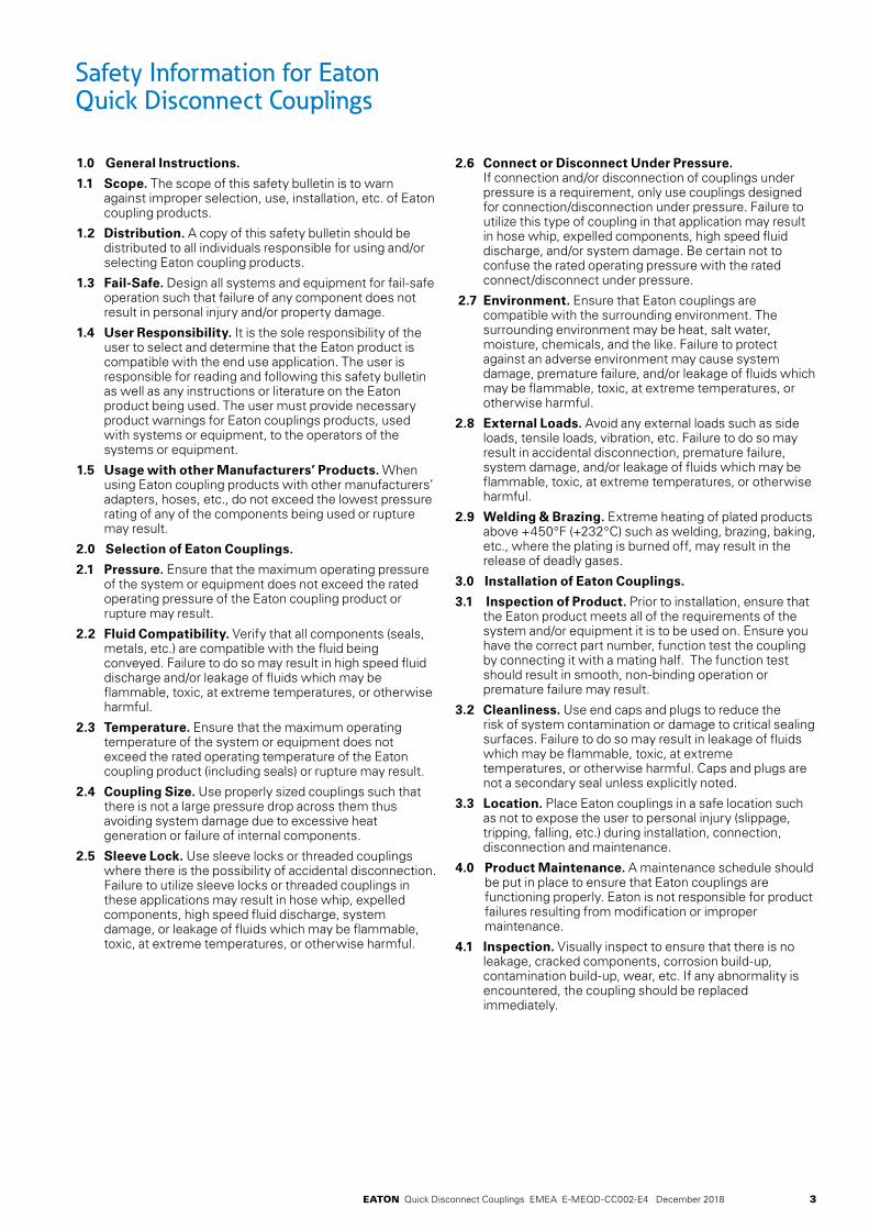
Safety Information for Eaton Quick Disconnect Couplings
1.0 General Instructions.
1.1 Scope. The scope of this safety bulletin is to warn against improper selection, use, installation, etc. of Eaton coupling products.
1.2 Distribution. A copy of this safety bulletin should be distributed to all individuals responsible for using and/or selecting Eaton coupling products.
1.3 Fail-Safe. Design all systems and equipment for fail-safe operation such that failure of any component does not result in personal injury and/or property damage.
1.4 User Responsibility. It is the sole responsibility of the user to select and determine that the Eaton product is compatible with the end use application. The user is responsible for reading and following this safety bulletin as well as any instructions or literature on the Eaton product being used. The user must provide necessary product warnings for Eaton couplings products, used with systems or equipment, to the operators of the systems or equipment.
1.5 Usage with other Manufacturers’ Products. When using Eaton coupling products with other manufacturers’ adapters, hoses, etc., do not exceed the lowest pressure rating of any of the components being used or rupture may result.
2.0 Selection of Eaton Couplings.
2.1 Pressure. Ensure that the maximum operating pressure of the system or equipment does not exceed the rated operating pressure of the Eaton coupling product or rupture may result.
2.2 Fluid Compatibility. Verify that all components (seals, metals, etc.) are compatible with the fluid being conveyed. Failure to do so may result in high speed fluid discharge and/or leakage of fluids which may be flammable, toxic, at extreme temperatures, or otherwise harmful.
2.3 Temperature. Ensure that the maximum operating temperature of the system or equipment does not exceed the rated operating temperature of the Eaton coupling product (including seals) or rupture may result.
2.4 Coupling Size. Use properly sized couplings such that there is not a large pressure drop across them thus avoiding system damage due to excessive heat generation or failure of internal components.
2.5 Sleeve Lock. Use sleeve locks or threaded couplings where there is the possibility of accidental disconnection. Failure to utilize sleeve locks or threaded couplings in these applications may result in hose whip, expelled components, high speed fluid discharge, system damage, or leakage of fluids which may be flammable, toxic, at extreme temperatures, or otherwise harmful.
2.6 Connect or Disconnect Under Pressure. If connection and/or disconnection of couplings under pressure is a requirement, only use couplings designed for connection/disconnection under pressure. Failure to utilize this type of coupling in that application may result in hose whip, expelled components, high speed fluid discharge, and/or system damage. Be certain not to confuse the rated operating pressure with the rated connect/disconnect under pressure.
2.7 Environment. Ensure that Eaton couplings are compatible with the surrounding environment. The surrounding environment may be heat, salt water, moisture, chemicals, and the like. Failure to protect against an adverse environment may cause system damage, premature failure, and/or leakage of fluids which may be flammable, toxic, at extreme temperatures, or otherwise harmful.
2.8 External Loads. Avoid any external loads such as side loads, tensile loads, vibration, etc. Failure to do so may result in accidental disconnection, premature failure, system damage, and/or leakage of fluids which may be flammable, toxic, at extreme temperatures, or otherwise harmful.
2.9 Welding & Brazing. Extreme heating of plated products above +450°F (+232°C) such as welding, brazing, baking, etc., where the plating is burned off, may result in the release of deadly gases.
3.0 Installation of Eaton Couplings.
3.1 Inspection of Product. Prior to installation, ensure that the Eaton product meets all of the requirements of the system and/or equipment it is to be used on. Ensure you have the correct part number, function test the coupling by connecting it with a mating half. The function test should result in smooth, non-binding operation or premature failure may result.
3.2 Cleanliness. Use end caps and plugs to reduce the risk of system contamination or damage to critical sealing surfaces. Failure to do so may result in leakage of fluids which may be flammable, toxic, at extreme temperatures, or otherwise harmful. Caps and plugs are not a secondary seal unless explicitly noted.
3.3 Location. Place Eaton couplings in a safe location such as not to expose the user to personal injury (slippage, tripping, falling, etc.) during installation, connection, disconnection and maintenance.
4.0 Product Maintenance. A maintenance schedule should be put in place to ensure that Eaton couplings are functioning properly. Eaton is not responsible for product failures resulting from modification or improper maintenance.
4.1 Inspection. Visually inspect to ensure that there is no leakage, cracked components, corrosion build-up, contamination build-up, wear, etc. If any abnormality is encountered, the coupling should be replaced immediately.

4 EATON Quick Disconnect Couplings EMEA E-MEQD-CC002-E4 December 2018
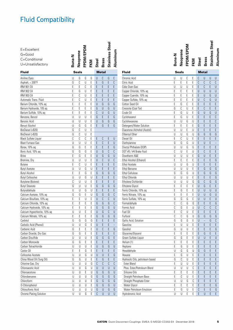
Fluid Compatibility
This chart indicates the suitability of various elastomers and metals for use with fluids to be conveyed. It is intended for use with Eaton couplings and should not be used to determine compatibility for other products. It is intended as a guide only and is not a guarantee. Final selection of the proper seal or material of metal components is further dependent on many factors including pressure, fluid and ambient temperature, concentration, duration of exposure, etc.
How to Use the Chart1. Both the elastomer and the metal must be considered
when determining suitability of combination for a coupling.
2. Locate the fluid to be conveyed and determine the suitability of the elastomeric and metal components according to the resistance rating shown for each.
3. Dimensional and operation specifications for each coupling can be found on the catalog pages.
4. Information on seal options for couplings, and how to specify them, are shown in the respective sections of this catalog.
5. Be sure to check the table below for maximum operating temperature range of the elastomer desired.
6. For further details on the products shown in this catalog, and their applications, consult your Eaton Sales Representative or Eaton Technical Support.
7. Coupling component materials may differ from body material. Refer to specific catalog pages.
E=ExcellentG=GoodC=ConditionalU=Unsatisfactory
Resistance Rating Key
E = Excellent – Fluid has little or no effect
G = Good – Fluid has minor to moderate effect
C = Conditional – Service conditions should be described to Eaton for determination of suitability for application
U = Unsatisfactory
The differences between ratings “E” and “G” are relative. Both indicate satisfactory service. Where there is a choice, the materials rated “E” may be expected to give better or longer service than those rated “G”.
Bu
na-
N
Neo
pre
ne
FPD
M/E
PD
M
FKM
Ste
el
Bra
ss
Sta
inle
ss S
teel
Alu
min
um
Bu
na-
N
Neo
pre
ne
FPD
M/E
PD
M
FKM
Ste
el
Bra
ss
Sta
inle
ss S
teel
Alu
min
um
Acetaldehyde U C C U G E E EAcetic Acid, 10% U U E G U U C CAcetic Acid, Glacial U U C U U U C CAcetone U U G U E E E EAcetophenone U U E U E E E CAcetyl Acetone U U G U U C C CAcetyl Chloride U U U E C C C UAcetylene (1) G U G E E E E EAir, Hot (Up to +160°F) E E E E E E E EAir, Hot (161°F – 200°F) C G E E E E E EAir, Hot (201°F – 300°F) U U G E E E E EAir Wet, below 160°F E E E E U G E EAluminum Chloride, 10% aq E E E E U U U UAluminum Fluoride, 10% aq E E E E U U U EAluminum Nitrate, 10% aq E E E E U U C C
Aluminum Sulfate, 10% aq E E E E U C E CAlums, 10% aq E E E E U C E CAmmonia, Cold E E E U E U E EAmmonia, Hot U G G U E U E EAmmonia, Anhydrous G G E U E U E EAmmonia, Aqueous E E E U E U E EAmmonium Carbonate, 10% aq U E E U C U C CAmmonium Chloride, 10% aq E E E U U U C UAmmonium Hydroxide, 10% aq C C E C G U C CAmmonium Nitrate, 10% aq E G E U G U G GAmmonium Phosphate, 10% aq E E E – U C G UAmmonium Sulfate/Sulfide, 10% aq E E E U U U G UAmyl Acetate U U G U E E E EAmyl Alcohol G C E G G G E UAniline, Aniline Oil U U G U E U E G
Fluid Seals Metal Fluid Seals Metal
The charts below are intended for reference use only. The information in this chart pertains strictly to material compatibility and is not intended to be used as an application guide.
5EATON Quick Disconnect Couplings EMEA E-MEQD-CC002-E4 December 2018
Bu
na-
N
Neo
pre
ne
FPD
M/E
PD
M
FKM
Ste
el
Bra
ss
Sta
inle
ss S
teel
Alu
min
um
Bu
na-
N
Neo
pre
ne
FPD
M/E
PD
M
FKM
Ste
el
Bra
ss
Sta
inle
ss S
teel
Alu
min
um
Fluid Seals Metal Fluid Seals Metal
Aniline Dyes U G G G U C G CAsphalt, < 200°F G C U E E G E CIRM 901 Oil E E C E E E E EIRM 902 Oil E G U E E E E EIRM 903 Oil E C U E E E E EAutomatic Trans. Fluid E C U E E E E EBarium Chloride, 10% aq E E E E U G G GBarium Hydroxide, 105 aq E E E E G U G UBarium Sulfide, 10% aq E E E E C U G UBenzene, Benzol U U U E G E E GBenzoic Acid U U U E U G G GBenzyl Alcohol U G G E E G E GBioDiesel (<B20) G C U E BioDiesel (>B20) G C U E Black Sulfate Liquor C C C E E C E UBlast Furnace Gas U U U E E C E UBorax, 10% aq G G E E E E E GBoric Acid, 10% aq G G G E U G C CBrine E G E E U G G UBromine, Dry U U U E U C U CButane E C U E E E E EButyl Acetate U U G U E E E EButyl Alcohol E E G E G G G GButyl Cellosolve U U G U E E E EButylene (Butene) C U U E E E E EButyl Stearate G U U E G G G GButyraldehyde U U G U E E E ECalcium Acetate, 10% aq G G E U G G G CCalcium Bisulfate, 10% aq E E U E U C C UCalcium Chloride, 10% aq E E E E G G G CCalcium Hydroxide, 10% aq E E E E G G G UCalcium Hypochlorite, 10% aq U U E E U G C UCalcium Nitrate, 10% aq E E E E G G G GCarbitol G G G G E E E ECarbolic Acid (Phenol) U U G E U E E –Carbonic Acid G E E E U C E GCarbon Dioxide, Dry Gas G G E E E E E ECarbon Disulfide U U U E G G G ECarbon Monoxide G G E E E E E ECarbon Tetrachloride U U U E U G G UCastor Oil E E G E E E E ECellosolve Acetate U U G U U U E GChina Wood Oil (Tung Oil) G G U E E G E EChlorine Gas, Dry U U U G C C C CChloroacetic Acid U U G U U U U UChloroacetone U U E U G G G UChlorobenzene U U U G G G G GChloroform U U U E G G G GO-Chlorophenol U U U E G G G UChlosulfonic Acid U U U U G U G GChrome Plating Solution U U G E C U U U
Chromic Acid U U C E C U U UCitric Acid E E E E C C C CCoke Oven Gas U U U E E C E UCopper Chloride, 10% aq E E E E U U U UCopper Cyanide, 10% aq E E E E E U G UCopper Sulfate, 10% aq E E E E U C G UCotton Seed Oil E G C E E E E ECreosote (Coal Tar) G C U E E C E ECrude Oil E G U E G U G UCyclohexanol E G U E E E E CCyclohexanone U U G U E E E CDetergent/Water Solution E E E E G E E EDiacetone Alchohol (Acetol) U U E U E E E EDibenzyl Ether U U G U G G G GDiesel Oil E C U E E E E EDiethylamine G G G U E U E –Dioctyl Phthalate (DOP) U U G G E E E EDOT #3 / #4 Brake fluid C U E U E C E EDowtherm A&E U U U E G U E EEthyl Alcohol (Ethanol) E E E E E E E GEthyl Acetate U U G U E E E EEthyl Benzene U U U E E G G GEthyl Cellulose G G G U E G G GEthyl Chloride U U U E E E E GEthylene Dichloride U U U G G C G GEthylene Glycol E E E E U G E EFerric Chloride, 10% aq E G E E U U U UFerric Nitrate, 10% aq E E E E U U G UFerric Sulfate, 10% aq G G G E U U E UFormaldehyde C C G G E E E GFormic Acid C G E U U C C CFuel Oil E C U E E E E EFurfural C C G U G G G GGallic Acid, Solution G G G E U – G CGasoline E U U E E E E EGasohol G U U E E E E GGlycerine/Glycerol E E E E E G E EGreen Sulfate Liquor G G E E U U E UHelium (1) E E E E E E E EHeptane E G U E E E E EHexaldehyde U G G U G G E EHexane E G U E E E E EHydraulic Oils, petroleum based G C U E E E E E Ester Blend E U U E E E E E Phos. Ester/Petroleum Blend U U U C E E E E Silicone Oils E E E E E E E E Straight Petroleum Base E C U E E E E E Straight Phosphate Ester U U G C E E E E Water Glycol E E E E E E E G Water Petroleum Emulsion E G U E C E E GHydrobromic Acid U U E E E U E E
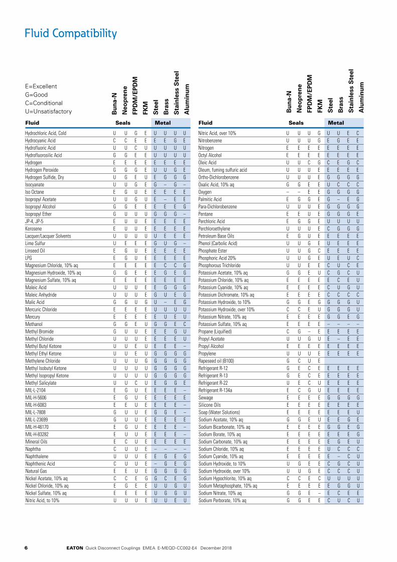
Fluid Compatibility
E=ExcellentG=GoodC=ConditionalU=Unsatisfactory
6 EATON Quick Disconnect Couplings EMEA E-MEQD-CC002-E4 December 2018
Bu
na-
N
Neo
pre
ne
FPD
M/E
PD
M
FKM
Ste
el
Bra
ss
Sta
inle
ss S
teel
Alu
min
um
Bu
na-
N
Neo
pre
ne
FPD
M/E
PD
M
FKM
Ste
el
Bra
ss
Sta
inle
ss S
teel
Alu
min
um
Fluid Seals Metal Fluid Seals Metal
Hydrochloric Acid, Cold U U G E U U U UHydrocyanic Acid C C E E E E G EHydrofluoric Acid U U C U U U U UHydrofluorosilic Acid G G E E U U U UHydrogen E E E E E E E EHydrogen Peroxide G G G E U U G EHydrogen Sulfide, Dry U G E U E G G GIsocyanate U U G E G – G –Iso Octane E G U E E E E EIsopropyl Acetate U U G U E – E EIsopropyl Alcohol G G E E E E E GIsopropyl Ether G U U U G G G –JP-4, JP-5 E U U E E E E EKerosene E U U E E E E ELacquer/Lacquer Solvents U U U U U E E ELime Sulfur U E E E G U G –Linseed Oil E G U E E E E ELPG E G U E E E E EMagnesium Chloride, 10% aq E E E E E C C GMagnesium Hydroxide, 10% aq G G E E E G E GMagnesium Sulfate, 10% aq E E E E E E E EMaleic Acid U U U E E G G GMaleic Anhydride U U U E G U E GMalic Acid G G U G U – E GMercuric Chloride E E E E U U U UMercury E E E E E U E UMethanol G G E U G G E CMethyl Bromide G U U E E E G UMethyl Chloride U U U E E E E UMethyl Butyl Ketone U U E U E E E –Methyl Ethyl Ketone U U E U G G G GMethylene Chloride U U U G G G G GMethyl Isobutyl Ketone U U U U G G G GMethyl Isopropyl Ketone U U U U G G G GMethyl Salicylate U U C U E G G EMIL-L-2104 E G U E E E E –MIL-H-5606 E G U E E E E EMIL-H-6083 E E U E E E E –MIL-L-7808 G U U E G G E –MIL-L-23699 G U U E E E E EMIL-H-46170 E G U E E E E –MIL-H-83282 E U U E E E E –Mineral Oils E C U E E E E ENaphtha C U U E – – – –Naphthalene U U U E E G E GNaphthenic Acid C U U E – G E GNatural Gas E E U E G G G GNickel Acetate, 10% aq C C E G G C E GNickel Chloride, 10% aq E G E E U U G UNickel Sulfate, 10% aq E E E E U G G UNitric Acid, to 10% U U U E U U E U
Nitric Acid, over 10% U U U G U U E CNitrobenzene U U U G E G E ENitrogen E E E E E E E EOctyl Alcohol E E E E E E E EOleic Acid U U C G C E G COleum, fuming sulfuric acid U U U E E E E EOrtho-Dichlorobenzene U U U E G G G GOxalic Acid, 10% aq G G E E U C C COxygen – – E E G G G GPalmitic Acid E G G E G – E GPara-Dichlorobenzene U U U E G G G GPentane E E U E G G G EPerchloric Acid E G G E U U U UPerchloroethylene U U U E C G G GPetroleum Base Oils E G U E E E E EPhenol (Carbolic Acid) U U G E U E E EPhosphate Ester U U G C E E E EPhosphoric Acid 20% U U G E U E U CPhosphorous Trichloride U U E E C U C EPotassium Acetate, 10% aq G G E U C G C UPotassium Chloride, 10% aq E E E E E C E UPotassium Cyanide, 10% aq E E E E C U G UPotassium Dichromate, 10% aq E E E E C C C CPotassium Hydroxide, to 10% G G E G G G G UPotassium Hydroxide, over 10% C C E U G G G UPotassium Nitrate, 10% aq E E E E G G E GPotassium Sulfate, 10% aq E E E E – – – –Propane (Liquified) C G – E E E E EPropyl Acetate U U G U E – E EPropyl Alcohol E E E E E E E EPropylene U U U E E E E ERapeseed oil (B100) G C U E Refrigerant R-12 G E C E E E E ERefrigerant R-13 G E C E E E E ERefrigerant R-22 U E C U E E E ERefrigerant R-134a E C G U E E E ESewage E E E E G G G GSilicone Oils E E E E E E E ESoap (Water Solutions) E E E E E E E USodium Acetate, 10% aq G G E U E E G ESodium Bicarbonate, 10% aq E E E E G G E GSodium Borate, 10% aq E E E E E E E GSodium Carbonate, 10% aq E E E E E G E USodium Chloride, 10% aq E E E E U C C CSodium Cyanide, 10% aq E E E E E – C USodium Hydroxide, to 10% U G E E C G C USodium Hydroxide, over 10% U U G E C C C USodium Hypochlorite, 10% aq C C E C U U U USodium Metaphosphate, 10% aq E E E E E G G USodium Nitrate, 10% aq G G E – E C E ESodium Perborate, 10% aq G G E E C U C U
Fluid Compatibility
E=ExcellentG=GoodC=ConditionalU=Unsatisfactory
7EATON Quick Disconnect Couplings EMEA E-MEQD-CC002-E4 December 2018
Bu
na-
N
Neo
pre
ne
FPD
M/E
PD
M
FKM
Ste
el
Bra
ss
Sta
inle
ss S
teel
Alu
min
um
Bu
na-
N
Neo
pre
ne
FPD
M/E
PD
M
FKM
Ste
el
Bra
ss
Sta
inle
ss S
teel
Alu
min
um
Fluid Seals Metal Fluid Seals Metal
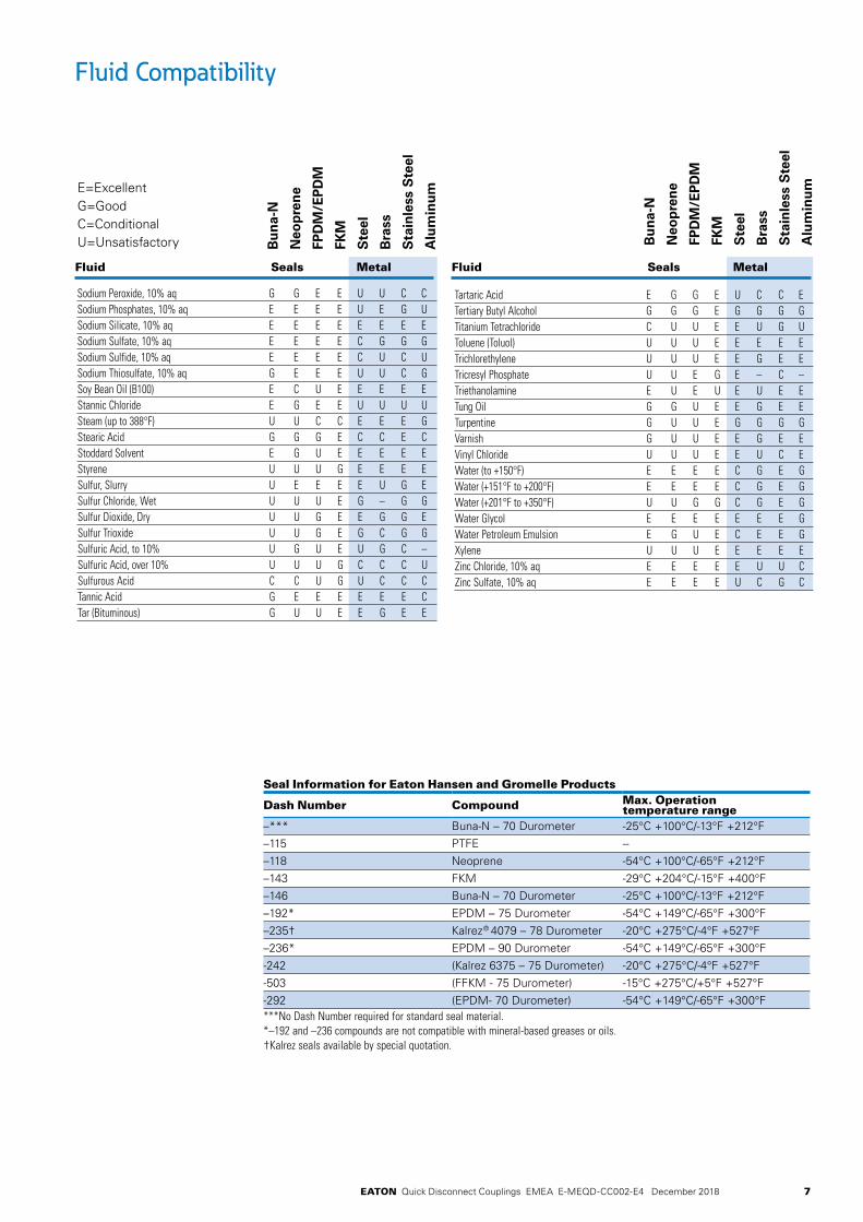
Fluid Compatibility
E=ExcellentG=GoodC=ConditionalU=Unsatisfactory
Sodium Peroxide, 10% aq G G E E U U C CSodium Phosphates, 10% aq E E E E U E G USodium Silicate, 10% aq E E E E E E E ESodium Sulfate, 10% aq E E E E C G G GSodium Sulfide, 10% aq E E E E C U C USodium Thiosulfate, 10% aq G E E E U U C GSoy Bean Oil (B100) E C U E E E E EStannic Chloride E G E E U U U USteam (up to 388°F) U U C C E E E GStearic Acid G G G E C C E CStoddard Solvent E G U E E E E EStyrene U U U G E E E ESulfur, Slurry U E E E E U G ESulfur Chloride, Wet U U U E G – G GSulfur Dioxide, Dry U U G E E G G ESulfur Trioxide U U G E G C G GSulfuric Acid, to 10% U G U E U G C –Sulfuric Acid, over 10% U U U G C C C USulfurous Acid C C U G U C C CTannic Acid G E E E E E E CTar (Bituminous) G U U E E G E E
Tartaric Acid E G G E U C C ETertiary Butyl Alcohol G G G E G G G GTitanium Tetrachloride C U U E E U G UToluene (Toluol) U U U E E E E ETrichlorethylene U U U E E G E ETricresyl Phosphate U U E G E – C –Triethanolamine E U E U E U E ETung Oil G G U E E G E ETurpentine G U U E G G G GVarnish G U U E E G E EVinyl Chloride U U U E E U C EWater (to +150°F) E E E E C G E GWater (+151°F to +200°F) E E E E C G E GWater (+201°F to +350°F) U U G G C G E GWater Glycol E E E E E E E GWater Petroleum Emulsion E G U E C E E GXylene U U U E E E E EZinc Chloride, 10% aq E E E E E U U CZinc Sulfate, 10% aq E E E E U C G C
Seal Information for Eaton Hansen and Gromelle Products
Dash Number Compound Max. Operation temperature range
–*** Buna-N – 70 Durometer -25°C +100°C/-13°F +212°F–115 PTFE --–118 Neoprene -54°C +100°C/-65°F +212°F–143 FKM -29°C +204°C/-15°F +400°F–146 Buna-N – 70 Durometer -25°C +100°C/-13°F +212°F–192* EPDM – 75 Durometer -54°C +149°C/-65°F +300°F–235† Kalrez® 4079 – 78 Durometer -20°C +275°C/-4°F +527°F–236* EPDM – 90 Durometer -54°C +149°C/-65°F +300°F-242 (Kalrez 6375 – 75 Durometer) -20°C +275°C/-4°F +527°F-503 (FFKM - 75 Durometer) -15°C +275°C/+5°F +527°F-292 (EPDM- 70 Durometer) -54°C +149°C/-65°F +300°F***No Dash Number required for standard seal material.*–192 and –236 compounds are not compatible with mineral-based greases or oils.†Kalrez seals available by special quotation.
8
FLUID
TRAN
SFERA
ND
HYD
RAU
LICPN
EUM
ATICSPECIA
L APPLICATIO
NS
DIA
GN
OSTIC
AG
RICULTU
REREFRIG
ERAN
T
EATON Quick Disconnect Couplings EMEA E-MEQD-CC002-E4 December 2018
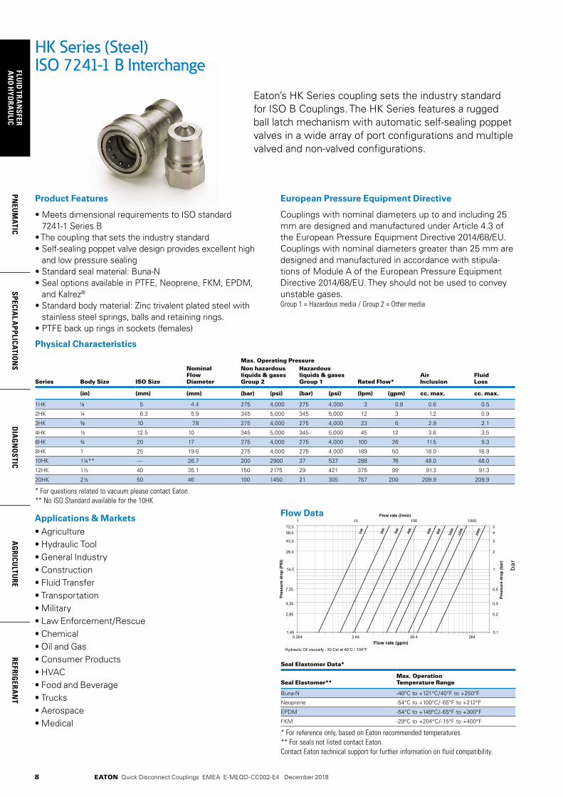
Physical Characteristics
Max. Operating Pressure
Series Body Size ISO Size
NominalFlow Diameter
Non hazardous liquids & gases Group 2
Hazardous liquids & gases Group 1 Rated Flow*
AirInclusion
FluidLoss
(in) (mm) (mm) (bar) (psi) (bar) (psi) (lpm) (gpm) cc. max. cc. max.
1HK 5 4.4 275 4,000 275 4,000 3 0.8 0.6 0.5
2HK ¼ 6.3 5.9 345 5,000 345 5,000 12 3 1.2 0.9
3HK 10 7.8 275 4,000 275 4,000 23 6 2.9 2.1
4HK ½ 12.5 10 345 5,000 345 5,000 45 12 3.6 3.5
6HK ¾ 20 17 275 4,000 275 4,000 100 26 11.5 9.3
8HK 1 25 19.6 275 4,000 275 4,000 189 50 18.0 16.9
10HK 1¼** — 26.7 200 2900 37 537 288 76 48.0 48.0
12HK 1½ 40 35.1 150 2175 29 421 375 99 91.3 91.3
20HK 2½ 50 46 100 1450 21 305 757 200 209.9 209.9
* For questions related to vacuum please contact Eaton.** No ISO Standard available for the 10HK
Eaton’s HK Series coupling sets the industry standard for ISO B Couplings. The HK Series features a rugged ball latch mechanism with automatic self-sealing poppet valves in a wide array of port configurations and multiple valved and non-valved configurations.
• Meets dimensional requirements to ISO standard 7241-1 Series B
• The coupling that sets the industry standard• Self-sealing poppet valve design provides excellent high
and low pressure sealing• Standard seal material: Buna-N• Seal options available in PTFE, Neoprene, FKM, EPDM,
and Kalrez®
• Standard body material: Zinc trivalent plated steel with stainless steel springs, balls and retaining rings.
• PTFE back up rings in sockets (females)
Product Features
HK Series (Steel)ISO 7241-1 B Interchange
Seal Elastomer Data*
Seal Elastomer**Max. Operation Temperature Range
Buna-N -40°C to +121°C/40°F to +250°F
Neoprene -54°C to +100°C/-65°F to +212°F
EPDM -54°C to +149°C/-65°F to +300°F
FKM -29°C to +204°C/-15°F to +400°F
* For reference only, based on Eaton recommended temperatures.** For seals not listed contact Eaton.Contact Eaton technical support for further information on fluid compatibility.
Applications & Markets• Agriculture• Hydraulic Tool• General Industry• Construction• Fluid Transfer• Transportation• Military• Law Enforcement/Rescue• Chemical• Oil and Gas• Consumer Products• HVAC• Food and Beverage• Trucks• Aerospace• Medical
Couplings with nominal diameters up to and including 25 mm are designed and manufactured under Article 4.3 of the European Pressure Equipment Directive 2014/68/EU. Couplings with nominal diameters greater than 25 mm are designed and manufactured in accordance with stipula-tions of Module A of the European Pressure Equipment Directive 2014/68/EU. They should not be used to convey unstable gases.Group 1 = Hazardous media / Group 2 = Other media
European Pressure Equipment Directive
4624.6246.2462.01.45
14.5
0.1
1
0001001011
Flow rate (gpm)
Pres
sure
dro
p (P
SI)
Pres
sure
dro
p (b
ar)
Flow rate (l/min)
Hydraulic Oil viscosity : 30 Cst at 40°C / 104°F
72,558,0
43,5
29,0
2,90
4,35
7,25
54
3
2
0,2
0,3
0,5
Flow Datab
ar
9
PNEU
MAT
ICSP
ECIA
L A
PPLI
CATI
ON
SD
IAG
NO
STIC
AG
RICU
LTU
RERE
FRIG
ERA
NT
FLU
ID T
RAN
SFER
AN
D H
YDRA
ULI
C
EATON Quick Disconnect Couplings EMEA E-MEQD-CC002-E4 December 2018
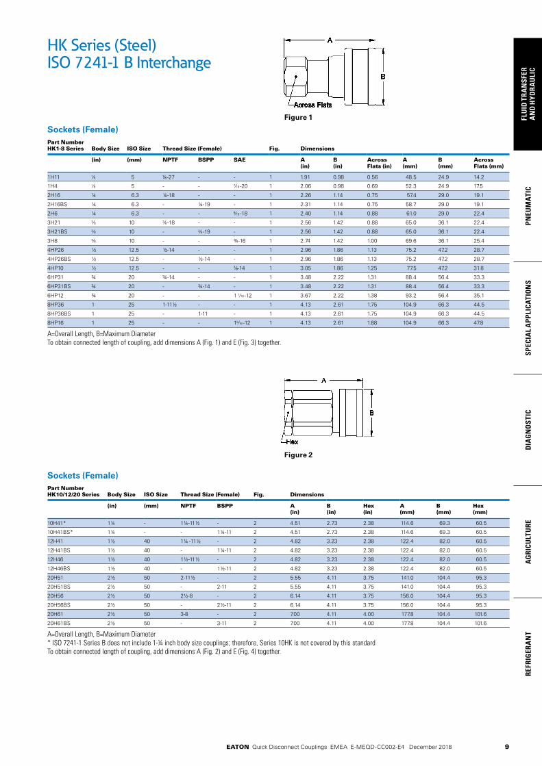
Sockets (Female)Part Number HK1-8 Series Body Size ISO Size Thread Size (Female) Fig. Dimensions
(in) (mm) NPTF BSPP SAE A (in)
B (in)
Across Flats (in)
A (mm)
B (mm)
Across Flats (mm)
1H11 5 -27 - - 1 1.91 0.98 0.56 48.5 24.9 14.2
1H4 5 - - -20 1 2.06 0.98 0.69 52.3 24.9 17.5
2H16 ¼ 6.3 ¼-18 - - 1 2.26 1.14 0.75 57.4 29.0 19.1
2H16BS ¼ 6.3 - ¼-19 - 1 2.31 1.14 0.75 58.7 29.0 19.1
2H6 ¼ 6.3 - - -18 1 2.40 1.14 0.88 61.0 29.0 22.4
3H21 10 -18 - - 1 2.56 1.42 0.88 65.0 36.1 22.4
3H21BS 10 - -19 - 1 2.56 1.42 0.88 65.0 36.1 22.4
3H8 10 - - ¾-16 1 2.74 1.42 1.00 69.6 36.1 25.4
4HP26 ½ 12.5 ½-14 - - 1 2.96 1.86 1.13 75.2 47.2 28.7
4HP26BS ½ 12.5 - ½-14 - 1 2.96 1.86 1.13 75.2 47.2 28.7
4HP10 ½ 12.5 - - -14 1 3.05 1.86 1.25 77.5 47.2 31.8
6HP31 ¾ 20 ¾-14 - - 1 3.48 2.22 1.31 88.4 56.4 33.3
6HP31BS ¾ 20 - ¾-14 - 1 3.48 2.22 1.31 88.4 56.4 33.3
6HP12 ¾ 20 - - 1 -12 1 3.67 2.22 1.38 93.2 56.4 35.1
8HP36 1 25 1-11½ - - 1 4.13 2.61 1.75 104.9 66.3 44.5
8HP36BS 1 25 - 1-11 - 1 4.13 2.61 1.75 104.9 66.3 44.5
8HP16 1 25 - - 1 -12 1 4.13 2.61 1.88 104.9 66.3 47.8
A=Overall Length, B=Maximum DiameterTo obtain connected length of coupling, add dimensions A (Fig. 1) and E (Fig. 3) together.
HK Series (Steel)ISO 7241-1 B Interchange
Sockets (Female)Part Number HK10/12/20 Series Body Size ISO Size Thread Size (Female) Fig. Dimensions
(in) (mm) NPTF BSPP A(in)
B (in)
Hex(in)
A(mm)
B(mm)
Hex(mm)
10H41* 1¼ - 1¼-11½ - 2 4.51 2.73 2.38 114.6 69.3 60.5
10H41BS* 1¼ - - 1¼-11 2 4.51 2.73 2.38 114.6 69.3 60.5
12H41 1½ 40 1¼ -11½ - 2 4.82 3.23 2.38 122.4 82.0 60.5
12H41BS 1½ 40 - 1¼-11 2 4.82 3.23 2.38 122.4 82.0 60.5
12H46 1½ 40 1½-11½ - 2 4.82 3.23 2.38 122.4 82.0 60.5
12H46BS 1½ 40 - 1½-11 2 4.82 3.23 2.38 122.4 82.0 60.5
20H51 2½ 50 2-11½ - 2 5.55 4.11 3.75 141.0 104.4 95.3
20H51BS 2½ 50 - 2-11 2 5.55 4.11 3.75 141.0 104.4 95.3
20H56 2½ 50 2½-8 - 2 6.14 4.11 3.75 156.0 104.4 95.3
20H56BS 2½ 50 - 2½-11 2 6.14 4.11 3.75 156.0 104.4 95.3
20H61 2½ 50 3-8 - 2 7.00 4.11 4.00 177.8 104.4 101.6
20H61BS 2½ 50 - 3-11 2 7.00 4.11 4.00 177.8 104.4 101.6
A=Overall Length, B=Maximum Diameter* ISO 7241-1 Series B does not include 1-¼ inch body size couplings; therefore, Series 10HK is not covered by this standardTo obtain connected length of coupling, add dimensions A (Fig. 2) and E (Fig. 4) together.
Figure 1
Figure 2

10
FLUID
TRAN
SFERA
ND
HYD
RAU
LICPN
EUM
ATICSPECIA
L APPLICATIO
NS
DIA
GN
OSTIC
AG
RICULTU
REREFRIG
ERAN
T
EATON Quick Disconnect Couplings EMEA E-MEQD-CC002-E4 December 2018
Plugs (Male)Part Number HK1-8 Series
Body Size
ISOSize
Thread Size (Female) Fig. Dimensions
(in) (mm) NPTF BSPP SAE C (in) D (in) E (in) Hex (in) C (mm) D (mm) E (mm) Hex (mm)
1K11 5 -27 - - 3 1.26 0.65 0.44 0.56 32.0 16.5 11.2 14.2
1K4 5 - - -20 3 1.41 0.79 0.59 0.69 35.8 20.1 15.0 17.5
2K16 ¼ 6.3 ¼-18 - - 3 1.52 0.87 0.56 0.75 38.6 22.1 14.2 19.1
2K16BS ¼ 6.3 - ¼-19 - 3 1.52 0.87 0.56 0.75 38.6 22.1 14.2 19.1
2K6 ¼ 6.3 - - -18 3 1.66 1.01 0.70 0.88 42.2 25.7 17.8 22.4
3K21 10 -18 - - 3 1.76 1.01 0.61 0.88 44.7 25.7 15.5 22.4
3K21BS 10 - -19 - 3 1.76 1.01 0.61 0.88 44.7 25.7 15.5 22.4
3K8 10 - - ¾-16 3 1.94 1.15 0.79 1.00 49.3 29.2 20.1 25.4
4KP26 ½ 12.5 ½-14 - - 3 2.03 1.30 0.76 1.13 51.6 33.0 19.3 28.7
4KP26BS ½ 12.5 - ½-14 - 3 2.03 1.30 0.76 1.13 51.6 33.0 19.3 28.7
4KP10 ½ 12.5 - - -14 3 2.11 1.37 0.84 1.19 53.6 34.8 21.3 30.2
6KP31 ¾ 20 ¾-14 - - 3 2.36 1.52 0.71 1.31 59.9 38.6 18.0 33.3
6KP31BS ¾ 20 - ¾-14 - 3 2.36 1.52 0.71 1.31 59.9 38.6 18.0 33.3
6KP12 ¾ 20 - - 1 -12 3 2.54 1.59 0.89 1.38 64.5 40.4 22.6 35.1
8KP36 1 25 1-11½ - - 3 2.85 1.88 0.97 1.63 72.4 47.8 24.6 41.4
8KP36BS 1 25 - 1-11 - 3 2.85 1.88 0.97 1.63 72.4 47.8 24.6 41.4
8KP16 1 25 - - 1 -12 3 2.85 2.17 0.97 1.88 72.4 55.1 24.6 47.8
C=Overall Length, D=Maximum Diameter, E=Exposed Length when Connected To obtain connected length of coupling, add dimensions A (Fig. 1) and E (Fig. 3) together.
HK Series (Steel)ISO 7241-1 B Interchange
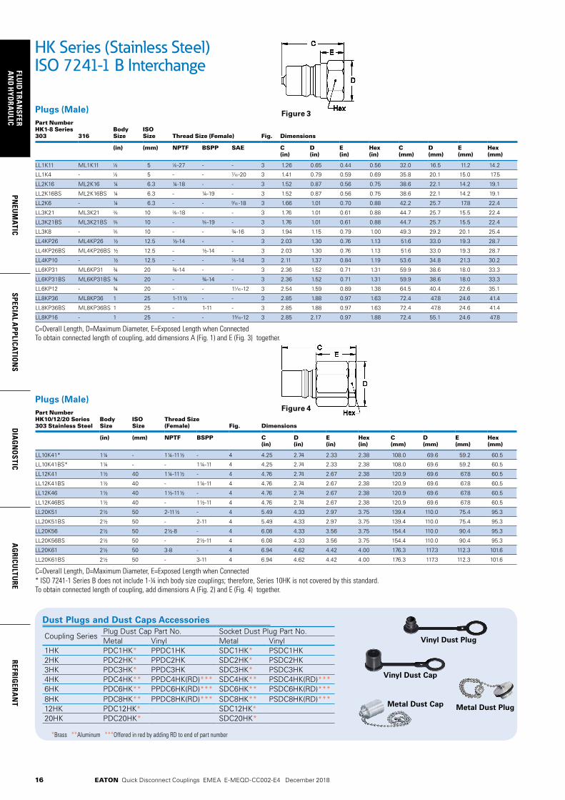
Dust Plugs and Dust Caps Accessories
Coupling SeriesPlug Dust Cap Part No. Socket Dust Plug Part No.Metal Vinyl Metal Vinyl
1HK PDC1HK* PPDC1HK SDC1HK* PSDC1HK2HK PDC2HK* PPDC2HK SDC2HK* PSDC2HK3HK PDC3HK* PPDC3HK SDC3HK* PSDC3HK4HK PDC4HK** PPDC4HK(RD)*** SDC4HK** PSDC4HK(RD)***6HK PDC6HK** PPDC6HK(RD)*** SDC6HK** PSDC6HK(RD)***8HK PDC8HK** PPDC8HK(RD)*** SDC8HK** PSDC8HK(RD)***12HK PDC12HK* SDC12HK*20HK PDC20HK* SDC20HK*
Vinyl Dust Plug
Vinyl Dust Cap
Metal Dust Cap Metal Dust Plug
*Brass **Aluminum ***Offered in red by adding RD to end of part number
Plugs (Male)Part Number HK10/12/20 Series
Body Size
ISO Size
Thread Size (Female) Fig. Dimensions
(in) (mm) NPTF BSPP C (in) D (in) E (in) Hex (in) C (mm) D (mm) E (mm) Hex (mm)
10K41* 1¼ - 1¼-11½ - 4 4.25 2.74 2.33 2.38 108.0 69.6 59.2 60.5
10K41BS* 1¼ - - 1¼-11 4 4.25 2.74 2.33 2.38 108.0 69.6 59.2 60.5
12K41 1½ 40 1¼-11½ - 4 4.76 2.74 2.67 2.38 120.9 69.6 67.8 60.5
12K41BS 1½ 40 - 1¼-11 4 4.76 2.74 2.67 2.38 120.9 69.6 67.8 60.5
12K46 1½ 40 1½-11½ - 4 4.76 2.74 2.67 2.38 120.9 69.6 67.8 60.5
12K46BS 1½ 40 - 1½-11 4 4.76 2.74 2.67 2.38 120.9 69.6 67.8 60.5
20K51 2½ 60 2-11½ - 4 5.49 4.33 2.97 3.75 139.4 110.0 75.4 95.3
20K51BS 2½ 60 - 2-11 4 5.49 4.33 2.97 3.75 139.4 110.0 75.4 95.3
20K56 2½ 60 2½-8 - 4 6.08 4.33 3.56 3.75 154.4 110.0 90.4 95.3
20K56BS 2½ 60 - 2½-11 4 6.08 4.33 3.56 3.75 154.4 110.0 90.4 95.3
20K61 2½ 60 3-8 - 4 6.94 4.62 4.42 4.00 176.3 117.3 112.3 101.6
20K61BS 2½ 60 - 3-11 4 6.94 4.62 4.42 4.00 176.3 117.3 112.3 101.6
C=Overall Length, D=Maximum Diameter, E=Exposed Length when Connected* ISO 7241-1 Series B does not include 1-¼ inch body size couplings; therefore, Series 10HK is not covered by this standard To obtain connected length of coupling, add dimensions A (Fig. 2) and E (Fig. 4) together.
Figure 3
Figure 4

11
PNEU
MAT
ICSP
ECIA
L A
PPLI
CATI
ON
SD
IAG
NO
STIC
AG
RICU
LTU
RERE
FRIG
ERA
NT
FLU
ID T
RAN
SFER
AN
D H
YDRA
ULI
C
EATON Quick Disconnect Couplings EMEA E-MEQD-CC002-E4 December 2018
HK Series (Brass)ISO 7241-1 B Interchange
Eaton’s HK brass is a general purpose industrial interchange coupling available in valved or non-valved designs, offered in brass for excelllent corrosion resistance in rugged applications where stainless steel is unacceptable. The HK Series features a ball latch mechanism with automatic self-sealing poppet valves.
• Meets dimensional requirements to ISO standard 7241-1 Series B
• Brass construction with stainless steel springs for greater corrosion resistance and fluid compatibility
• Self-sealing poppet valves provide excellent high and low pressure sealing
• Standard seal material: Buna-N• Seal options available in PTFE, Neoprene, FKM, EPDM, and
Kalrez®
Product Features
4624.6246.2462.01.45
14.5
0.1
1
0001001011
Flow rate (gpm)
Pres
sure
dro
p (P
SI)
Pres
sure
dro
p (b
ar)
Flow rate (l/min)
Hydraulic Oil viscosity : 30 Cst at 40°C / 104°F
72,558,0
43,5
29,0
2,90
4,35
7,25
54
3
2
0,2
0,3
0,5
Applications & Markets• Agriculture• Hydraulic Tool• General Industry• Construction• Fluid Transfer• Chemical• Oil and Gas• Transportation• Food and Beverage• Trucks• Nuclear
Seal Elastomer Data*
Seal Elastomer Max. Operation Temperature Range
Buna-N -40°C to +121°C/40°F to +250°F
Neoprene -54°C to +100°C/-65°F to +212°F
EPDM -54°C to +149°C/-65°C to +300°F
FKM -29°C to +204°C/-15°F to +400°F
* For reference only, based on Eaton recommended temperatures.Contact Eaton technical support for further information on fluid compatibility.
Flow Data
Couplings with nominal diameters up to and including 25 mm are designed and manufactured under Article 4.3 of the European Pressure Equipment Directive 2014/68/EU. Couplings with nominal diameters greater than 25 mm are designed and manufactured in accordance with stipula-tions of Module A of the European Pressure Equipment Directive 2014/68/EU. They should not be used to convey unstable gases.Group 1 = Hazardous media / Group 2 = Other media
European Pressure Equipment Directive
Physical Characteristics
Max. Operating Pressure
Series Body Size ISO Size
NominalFlow Diameter
Non hazardous liquids & gases Group 2
Hazardous liquids & gases Group 1 Rated Flow*
AirInclusion
FluidLoss
(in) (mm) (mm) (bar) (psi) (bar) (psi) (lpm) (gpm) cc. max. cc. max.
1HK 5 4.4 207 3,000 207 3,000 3 0.8 0.6 0.5
2HK ¼ 6.3 5.9 186 2,700 186 2,700 12 3 1.2 0.9
3HK 10 7.8 152 2,200 152 2,200 23 6 2.9 2.1
4HK ½ 12.5 10 155 2,250 155 2,250 45 12 3.6 3.5
6HK ¾ 20 17 138 2,000 138 2,000 100 26 11.5 9.3
8HK 1 25 19.6 103 1,500 103 1,500 189 50 18.0 16.9
10HK 1¼** — 26.7 83 1,200 37 537 288 76 48.0 48.0
12HK 1½ 40 35.1 104 1,500 29 421 375 99 91.3 91.3
20HK 2½ 50 46 49 700 21 305 757 200 209.9 209.9
* For questions related to vacuum please contact Eaton.** No ISO Standard available for the 10HK

12
FLUID
TRAN
SFERA
ND
HYD
RAU
LICPN
EUM
ATICSPECIA
L APPLICATIO
NS
DIA
GN
OSTIC
AG
RICULTU
REREFRIG
ERAN
T
EATON Quick Disconnect Couplings EMEA E-MEQD-CC002-E4 December 2018
Sockets (Female)Part Number HK1-8 Series Body Size ISO Size Thread Size (Female) Fig. Dimensions
(in) (mm) NPTF BSPP A (in)
B (in)
Across Flats (in)
A (mm)
B (mm)
Across Flats (mm)
B1H11 5 -27 - 1 1.91 0.98 0.56 48.5 24.9 14.2
B2H16 ¼ 6.3 ¼-18 - 1 2.26 1.14 0.75 57.4 29.0 19.1
B2H16BS ¼ 6.3 - ¼-19 1 2.31 1.14 0.75 58.7 29.0 19.1
B3H21 10 -18 - 1 2.56 1.42 0.88 65.0 36.1 22.4
B3H21BS 10 - -19 1 2.56 1.42 0.88 65.0 36.1 22.4
B4HP26 ½ 12.5 ½-14 - 1 2.96 1.86 1.13 75.2 47.2 28.7
B4HP26BS ½ 12.5 - ½-14 1 2.96 1.86 1.13 75.2 47.2 28.7
B6HP31 ¾ 20 ¾-14 - 1 3.48 2.22 1.31 88.4 56.4 33.3
B6HP31BS ¾ 20 - ¾-14 1 3.48 2.22 1.31 88.4 56.4 33.3
B8HP36 1 25 1-11½ - 1 4.13 2.61 1.75 104.9 66.3 44.5
B8HP36BS 1 25 - 1-11 1 4.13 2.61 1.75 104.9 66.3 44.5
A=Overall Length, B=Maximum DiameterTo obtain connected length of coupling, add dimensions A (Fig. 1) and E (Fig. 3) together.
HK Series (Brass)ISO 7241-1 B Interchange
Sockets (Female)Part Number HK10/12/20 Series Body Size ISO Size Thread Size (Female) Fig. Dimensions
(in) (mm) NPTF BSPP A (in)
B (in)
Hex (in)
A (mm)
B (mm)
Hex (mm)
B10H41* 1¼ - 1¼-11½ - 2 4.51 2.73 2.38 114.6 69.3 60.5
B12H41 1½ 40 1¼-11½ - 2 4.82 3.23 2.38 122.4 82.0 60.5
B12H41BS 1½ 40 - 1¼-11 2 4.82 3.23 2.38 122.4 82.0 60.5
B12H46 1½ 40 1½-11 - 2 4.82 3.23 2.38 122.4 82.0 60.5
B12H46BS 1½ 40 - 1½-11 2 4.82 3.23 2.38 122.4 82.0 60.5
B20H51 2½ 50 2-11½ - 2 5.55 4.11 3.75 141.0 104.4 95.3
B20H51BS 2½ 50 - 2-11 2 5.55 4.11 3.75 141.0 104.4 95.3
B20H56 2½ 50 2½-8 - 2 6.14 4.11 3.75 156.0 104.4 95.3
B20H56BS 2½ 50 - 2½-11 2 6.14 4.11 3.75 156.0 104.4 95.3
B20H61 2½ 50 3-8 - 2 7.00 4.11 4.00 177.8 104.4 101.6
B20H61BS 2½ 50 - 3-11 2 7.00 4.11 4.00 177.8 104.4 101.6
A=Overall Length, B=Maximum Diameter* ISO 7241-1 Series B does not include 1-¼ inch body size couplings; therefore, Series 10HK is not covered by this standardTo obtain connected length of coupling, add dimensions A (Fig. 2) and E (Fig. 4) together.
Figure 1
Figure 2

13
PNEU
MAT
ICSP
ECIA
L A
PPLI
CATI
ON
SD
IAG
NO
STIC
AG
RICU
LTU
RERE
FRIG
ERA
NT
FLU
ID T
RAN
SFER
AN
D H
YDRA
ULI
C
EATON Quick Disconnect Couplings EMEA E-MEQD-CC002-E4 December 2018
Plugs (Male)Part Number HK1-8 Series Body Size ISO Size
Thread Size (Female) Fig. Dimensions
(in) (mm) NPTF BSPP C (in)
D (in)
E (in)
Hex (in)
C (mm)
D (mm)
E (mm)
Hex (mm)
B1K11 5 -27 - 3 1.26 0.65 0.44 0.56 32.0 16.5 11.2 14.2
B2K16 ¼ 6.3 ¼-18 - 3 1.52 0.87 0.56 0.75 38.6 22.1 14.2 19.1
B2K16BS ¼ 6.3 - ¼-19 3 1.52 0.87 0.56 0.75 38.6 22.1 14.2 19.1
B3K21 10 -18 - 3 1.76 1.01 0.61 0.88 44.7 25.7 15.5 22.4
B3K21BS 10 - -19 3 1.76 1.01 0.61 0.88 44.7 25.7 15.5 22.4
B4KP26 ½ 12.5 ½-14 - 3 2.03 1.30 0.76 1.13 51.6 33.0 19.3 28.7
B4KP26BS ½ 12.5 - ½-14 3 2.03 1.30 0.76 1.13 51.6 33.0 19.3 28.7
B6KP31 ¾ 20 ¾-14 - 3 2.36 1.52 0.71 1.31 59.9 38.6 18.0 33.3
B6KP31BS ¾ 20 - ¾-14 3 2.36 1.52 0.71 1.31 59.9 38.6 18.0 33.3
B8KP36 1 25 1-11½ - 3 2.85 1.88 0.97 1.63 72.4 47.8 24.6 41.4
B8KP36BS 1 25 - 1-11 3 2.85 1.88 0.97 1.63 72.4 47.8 24.6 41.4
C=Overall Length, D=Maximum Diameter, E=Exposed Length when ConnectedTo obtain connected length of coupling, add dimensions A (Fig. 1) and E (Fig. 3) together.
Plugs (Male)Part Number HK10/12/20 Series Body Size ISO Size
Thread Size (Female) Fig. Dimensions
(in) (mm) NPTF BSPP C (in)
D (in)
E (in)
Hex (in)
C (mm)
D (mm)
E (mm)
Hex (mm)
B10K41* 1¼ - 1¼-11½ - 4 4.25 2.74 2.33 2.38 108.0 69.6 59.2 60.5
B12K41 1½ 40 1¼-11½ - 4 4.76 2.74 2.67 2.38 120.9 69.6 67.8 60.5
B12K41BS 1½ 40 - 1¼-11 4 4.76 2.74 2.67 2.38 120.9 69.6 67.8 60.5
B12K46 1½ 40 1½-11½ - 4 4.76 2.74 2.67 2.38 120.9 69.6 67.8 60.5
B12K46BS 1½ 40 - 1½-11 4 4.76 2.74 2.67 2.38 120.9 69.6 67.8 60.5
B20K51 2½ 50 2-11½ - 4 5.49 4.33 2.97 3.75 139.4 110.0 75.4 95.3
B20K51BS 2½ 50 - 2-11 4 5.49 4.33 2.97 3.75 139.4 110.0 75.4 95.3
B20K56 2½ 50 2½-8 - 4 6.08 4.33 3.56 3.75 154.4 110.0 90.4 95.3
B20K56BS 2½ 50 - 2½-11 4 6.08 4.33 3.56 3.75 154.4 110.0 90.4 95.3
B20K61 2½ 50 3-8 - 4 6.94 4.62 4.42 4.00 176.3 117.3 112.3 101.6
B20K61BS 2½ 50 - 3-11 4 6.94 4.62 4.42 4.00 176.3 117.3 112.3 101.6
C=Overall Length, D=Maximum Diameter, E=Exposed Length when Connected* ISO 7241-1 Series B does not include 1-¼ inch body size couplings; therefore, Series 10HK is not covered by this standardTo obtain connected length of coupling, add dimensions A (Fig. 2) and E (Fig. 4) together.
HK Series (Brass)ISO 7241-1 B Interchange
Dust Plugs and Dust Caps Accessories
Coupling SeriesPlug Dust Cap Part No. Socket Dust Plug Part No.Metal Vinyl Metal Vinyl
1HK PDC1HK* PPDC1HK SDC1HK* PSDC1HK2HK PDC2HK* PPDC2HK SDC2HK* PSDC2HK3HK PDC3HK* PPDC3HK SDC3HK* PSDC3HK4HK PDC4HK** PPDC4HK(RD)*** SDC4HK** PSDC4HK(RD)***6HK PDC6HK** PPDC6HK(RD)*** SDC6HK** PSDC6HK(RD)***8HK PDC8HK** PPDC8HK(RD)*** SDC8HK** PSDC8HK(RD)***12HK PDC12HK* SDC12HK*20HK PDC20HK* SDC20HK*
*Brass **Aluminum ***Offered in red by adding RD to end of part number
Vinyl Dust Plug
Vinyl Dust Cap
Metal Dust Cap Metal Dust Plug
Figure 3
Figure 4

14
FLUID
TRAN
SFERA
ND
HYD
RAU
LICPN
EUM
ATICSPECIA
L APPLICATIO
NS
DIA
GN
OSTIC
AG
RICULTU
REREFRIG
ERAN
T
EATON Quick Disconnect Couplings EMEA E-MEQD-CC002-E4 December 2018
4624.6246.2462.01.45
14.5
0.1
1
0001001011
Flow rate (gpm)
Pres
sure
dro
p (P
SI)
Pres
sure
dro
p (b
ar)
Flow rate (l/min)
Hydraulic Oil viscosity : 30 Cst at 40°C / 104°F
72,558,0
43,5
29,0
2,90
4,35
7,25
54
3
2
0,2
0,3
0,5
Eaton’s HK stainless steel is a general purpose industrial interchange coupling available in valved or non-valved designs, offered in 303/316 grades of stainless steel for excellent corrosion resistance in rugged applications. The HK Series features a ball latch mechanism with automatic self-sealing poppet valves.
• Meets dimensional requirements to ISO standard 7241-1 Series B
• 303/316 Stainless steel construction for greater corrosion resistance and fluid compatibility
• Self-sealing poppet valves provide excellent high and low pressure sealing
• Standard body material: 303 or 316 Stainless Steel• Standard seal material: Buna-N• Seal options available in PTFE, Neoprene, FKM, EPDM, and
Kalrez®
Product Features
Seal Elastomer Data*
Seal Elastomer Max. Operation Temperature Range
Buna-N -40°C to +121°C/40°F to +250°F
Neoprene -54°C to +100°C/-65°F to +212°F
EPDM -54°C to +149°C/-65°C to +300°F
FKM -29°C to +204°C/-15°F to +400°F
*For reference only, based on Eaton recommended temperatures.Contact Eaton technical support for further information on fluid compatibility.
HK Series Series (Stainless Steel)ISO 7241-1 B Interchange
Applications & Markets• Agriculture• Hydraulic Tool• General Industry• Construction• Fluid Transfer• Transportation• Military• Law Enforcement/Rescue• Chemical• Oil and Gas• Consumer Products• HVAC• Food and Beverage• Trucks• Aerospace• Medical
Flow Data
Couplings with nominal diameters up to and including 25 mm are designed and manufactured under Article 4.3 of the European Pressure Equipment Directive 2014/68/EU. Couplings with nominal diameters greater than 25 mm are designed and manufactured in accordance with stipulations of Module A of the European Pressure Equipment Directive 2014/68/EU. They should not be used to convey unstable gases.Group 1 = Hazardous media / Group 2 = Other media
European Pressure Equipment Directive
Physical Characteristics
Max. Operating Pressure
Series Body Size ISO Size
NominalFlow Diameter
Non hazardous liquids & gases Group 2
Hazardous liquids & gases Group 1 Rated Flow*
AirInclusion
FluidLoss
(in) (mm) (mm) (bar) (psi) (bar) (psi) (lpm) (gpm) cc. max. cc. max.
1HK 5 4.4 344 5,000 344 5,000 3 0.8 0.6 0.5
2HK ¼ 6.3 5.9 255 3,700 255 3,700 12 3 1.2 0.9
3HK 10 7.8 255 3,700 255 3,700 23 6 2.9 2.1
4HK ½ 12.5 10 293 4,250 293 4,250 45 12 3.6 3.5
6HK ¾ 20 17 242 3,500 242 3,500 100 26 11.5 9.3
8HK 1 25 19.6 207 3,000 207 3,000 189 50 18.0 16.9
10HK 1¼** — 26.7 118 1,700 37 537 288 76 48.0 48.0
12HK 1½ 40 35.1 152 2,200 29 421 375 99 91.3 91.3
20HK 2½ 50 46 104 1,500 21 305 757 200 209.9 209.9
* For questions related to vacuum please contact Eaton.** No ISO Standard available for the 10HK

15
PNEU
MAT
ICSP
ECIA
L A
PPLI
CATI
ON
SD
IAG
NO
STIC
AG
RICU
LTU
RERE
FRIG
ERA
NT
FLU
ID T
RAN
SFER
AN
D H
YDRA
ULI
C
EATON Quick Disconnect Couplings EMEA E-MEQD-CC002-E4 December 2018
Sockets (Female)Part Number HK1-8 Series 303Stainless Steel
316Stainless Steel
Body Size
ISO Size Thread Size (Female) Fig. Dimensions
(in) (in) NPTF BSPP SAE A (in)
B (in)
Across Flats (in)
A (mm)
B (mm)
Across Flats (mm)
LL1H11 ML1H11 5 -27 - - 1 1.91 0.98 0.56 48.5 24.9 14.2
LL1H4 - 5 - - -20 1 2.06 0.98 0.69 52.3 24.9 17.5
LL2H16 ML2H16 ¼ 6.3 ¼-18 - - 1 2.26 1.14 0.75 57.4 29.0 19.1
LL2H16BS ML2H16BS ¼ 6.3 - ¼-19 - 1 2.31 1.14 0.75 58.7 29.0 19.1
LL2H6 - ¼ 6.3 - - -18 1 2.40 1.14 0.88 61.0 29.0 22.4
LL3H21 ML3H21 10 -18 - - 1 2.56 1.42 0.88 65.0 36.1 22.4
LL3H21BS ML3H21BS 10 - -19 - 1 2.56 1.42 0.88 65.0 36.1 22.4
LL3H8 - 10 - - ¾-16 1 2.74 1.42 1.00 69.6 36.1 25.4
LL4HP26 ML4HP26 ½ 12.5 ½-14 - - 1 2.96 1.86 1.13 75.2 47.2 28.7
LL4HP26BS ML4HP26BS ½ 12.5 - ½-14 - 1 2.96 1.86 1.13 75.2 47.2 28.7
LL4HP10 - ½ 12.5 - - -14 1 3.05 1.86 1.25 77.5 47.2 31.8
LL6HP31 ML6HP31 ¾ 20 ¾-14 - - 1 3.48 2.22 1.31 88.4 56.4 33.3
LL6HP31BS ML6HP31BS ¾ 20 - ¾-14 - 1 3.48 2.22 1.31 88.4 56.4 33.3
LL6HP12 - ¾ 20 - - -12 1 3.67 2.22 1.38 93.2 56.4 35.1
LL8HP36 ML8HP36 1 25 1-11½ - - 1 4.13 2.61 1.75 104.9 66.3 44.5
LL8HP36BS ML8HP36BS 1 25 - 1-11 - 1 4.13 2.61 1.75 104.9 66.3 44.5
LL8HP16 - 1 25 - - 11 -12 1 4.13 2.61 1.88 104.9 66.3 47.8
A=Overall Length, B=Maximum DiameterTo obtain connected length of coupling, add dimensions A (Fig. 1) and E (Fig. 3) together.
Sockets (Female)Part Number HK10/12/20 Series 303 Stainless Steel Body Size ISO Size Thread Size (Female) Fig. Dimensions
(in) (mm) NPTF BSPP A (in)
B (in)
Hex (in)
A (mm)
B (mm)
Hex (mm)
LL10H41* 1¼ - 1¼-11½ - 2 4.51 2.73 2.38 114.6 69.3 60.5
LL10H41BS* 1¼ - - 1¼-11 2 4.51 2.73 2.38 114.6 69.3 60.5
LL12H41 1½ 40 1¼-11½ - 2 4.82 3.23 2.38 122.4 82.0 60.5
LL12H41BS 1½ 40 - 1¼-11 2 4.82 3.23 2.38 122.4 82.0 60.5
LL12H46 1½ 40 1½-11½ - 2 4.82 3.23 2.38 122.4 82.0 60.5
LL12H46BS 1½ 40 - 1½-11 2 4.82 3.23 2.38 122.4 82.0 60.5
LL20H51 2½ 50 2-11½ - 2 5.55 4.11 3.75 141.0 104.4 95.3
LL20H51BS 2½ 50 - 2-11 2 5.55 4.11 3.75 141.0 104.4 95.3
LL20H56 2½ 50 2½-8 - 2 6.14 4.11 3.75 156.0 104.4 95.3
LL20H56BS 2½ 50 - 2½-11 2 6.14 4.11 3.75 156.0 104.4 95.3
LL20H61 2½ 50 3-8 - 2 7.00 4.11 4.00 177.8 104.4 101.6
LL20H61BS 2½ 50 - 3-11 2 7.00 4.11 4.00 177.8 104.4 101.6
A=Overall Length, B=Maximum Diameter* ISO 7241-1 Series B does not include 1-¼ inch body size couplings;therefore, Series 10HK is not covered by this standard.To obtain connected length of coupling, add dimensions A (Fig. 2) and E (Fig. 4) together.
HK Series Series (Stainless Steel)ISO 7241-1 B Interchange
Figure 1
Figure 2
16
FLUID
TRAN
SFERA
ND
HYD
RAU
LICPN
EUM
ATICSPECIA
L APPLICATIO
NS
DIA
GN
OSTIC
AG
RICULTU
REREFRIG
ERAN
T
EATON Quick Disconnect Couplings EMEA E-MEQD-CC002-E4 December 2018
Plugs (Male)Part Number HK1-8 Series303 316
Body Size
ISO Size Thread Size (Female) Fig. Dimensions
(in) (mm) NPTF BSPP SAE C (in)
D (in)
E (in)
Hex (in)
C (mm)
D (mm)
E (mm)
Hex (mm)
LL1K11 ML1K11 5 -27 - - 3 1.26 0.65 0.44 0.56 32.0 16.5 11.2 14.2
LL1K4 - 5 - - -20 3 1.41 0.79 0.59 0.69 35.8 20.1 15.0 17.5
LL2K16 ML2K16 ¼ 6.3 ¼-18 - - 3 1.52 0.87 0.56 0.75 38.6 22.1 14.2 19.1
LL2K16BS ML2K16BS ¼ 6.3 - ¼-19 - 3 1.52 0.87 0.56 0.75 38.6 22.1 14.2 19.1
LL2K6 - ¼ 6.3 - - -18 3 1.66 1.01 0.70 0.88 42.2 25.7 17.8 22.4
LL3K21 ML3K21 10 -18 - - 3 1.76 1.01 0.61 0.88 44.7 25.7 15.5 22.4
LL3K21BS ML3K21BS 10 - -19 - 3 1.76 1.01 0.61 0.88 44.7 25.7 15.5 22.4
LL3K8 - 10 - - ¾-16 3 1.94 1.15 0.79 1.00 49.3 29.2 20.1 25.4
LL4KP26 ML4KP26 ½ 12.5 ½-14 - - 3 2.03 1.30 0.76 1.13 51.6 33.0 19.3 28.7
LL4KP26BS ML4KP26BS ½ 12.5 - ½-14 - 3 2.03 1.30 0.76 1.13 51.6 33.0 19.3 28.7
LL4KP10 - ½ 12.5 - - -14 3 2.11 1.37 0.84 1.19 53.6 34.8 21.3 30.2
LL6KP31 ML6KP31 ¾ 20 ¾-14 - - 3 2.36 1.52 0.71 1.31 59.9 38.6 18.0 33.3
LL6KP31BS ML6KP31BS ¾ 20 - ¾-14 - 3 2.36 1.52 0.71 1.31 59.9 38.6 18.0 33.3
LL6KP12 - ¾ 20 - - 1 -12 3 2.54 1.59 0.89 1.38 64.5 40.4 22.6 35.1
LL8KP36 ML8KP36 1 25 1-11½ - - 3 2.85 1.88 0.97 1.63 72.4 47.8 24.6 41.4
LL8KP36BS ML8KP36BS 1 25 - 1-11 - 3 2.85 1.88 0.97 1.63 72.4 47.8 24.6 41.4
LL8KP16 - 1 25 - - 1 -12 3 2.85 2.17 0.97 1.88 72.4 55.1 24.6 47.8
C=Overall Length, D=Maximum Diameter, E=Exposed Length when ConnectedTo obtain connected length of coupling, add dimensions A (Fig. 1) and E (Fig. 3) together.
Plugs (Male)Part Number HK10/12/20 Series 303 Stainless Steel
Body Size
ISO Size
Thread Size (Female) Fig. Dimensions
(in) (mm) NPTF BSPP C (in)
D (in)
E (in)
Hex (in)
C (mm)
D (mm)
E (mm)
Hex (mm)
LL10K41* 1¼ - 1¼-11½ - 4 4.25 2.74 2.33 2.38 108.0 69.6 59.2 60.5
LL10K41BS* 1¼ - - 1¼-11 4 4.25 2.74 2.33 2.38 108.0 69.6 59.2 60.5
LL12K41 1½ 40 1¼-11½ - 4 4.76 2.74 2.67 2.38 120.9 69.6 67.8 60.5
LL12K41BS 1½ 40 - 1¼-11 4 4.76 2.74 2.67 2.38 120.9 69.6 67.8 60.5
LL12K46 1½ 40 1½-11½ - 4 4.76 2.74 2.67 2.38 120.9 69.6 67.8 60.5
LL12K46BS 1½ 40 - 1½-11 4 4.76 2.74 2.67 2.38 120.9 69.6 67.8 60.5
LL20K51 2½ 50 2-11½ - 4 5.49 4.33 2.97 3.75 139.4 110.0 75.4 95.3
LL20K51BS 2½ 50 - 2-11 4 5.49 4.33 2.97 3.75 139.4 110.0 75.4 95.3
LL20K56 2½ 50 2½-8 - 4 6.08 4.33 3.56 3.75 154.4 110.0 90.4 95.3
LL20K56BS 2½ 50 - 2½-11 4 6.08 4.33 3.56 3.75 154.4 110.0 90.4 95.3
LL20K61 2½ 50 3-8 - 4 6.94 4.62 4.42 4.00 176.3 117.3 112.3 101.6
LL20K61BS 2½ 50 - 3-11 4 6.94 4.62 4.42 4.00 176.3 117.3 112.3 101.6
C=Overall Length, D=Maximum Diameter, E=Exposed Length when Connected* ISO 7241-1 Series B does not include 1-¼ inch body size couplings; therefore, Series 10HK is not covered by this standard.To obtain connected length of coupling, add dimensions A (Fig. 2) and E (Fig. 4) together.
HK Series (Stainless Steel)ISO 7241-1 B Interchange
Dust Plugs and Dust Caps Accessories
Coupling SeriesPlug Dust Cap Part No. Socket Dust Plug Part No.Metal Vinyl Metal Vinyl
1HK PDC1HK* PPDC1HK SDC1HK* PSDC1HK2HK PDC2HK* PPDC2HK SDC2HK* PSDC2HK3HK PDC3HK* PPDC3HK SDC3HK* PSDC3HK4HK PDC4HK** PPDC4HK(RD)*** SDC4HK** PSDC4HK(RD)***6HK PDC6HK** PPDC6HK(RD)*** SDC6HK** PSDC6HK(RD)***8HK PDC8HK** PPDC8HK(RD)*** SDC8HK** PSDC8HK(RD)***12HK PDC12HK* SDC12HK*20HK PDC20HK* SDC20HK*
*Brass **Aluminum ***Offered in red by adding RD to end of part number
Vinyl Dust Plug
Vinyl Dust Cap
Metal Dust Cap Metal Dust Plug
Figure 3
Figure 4
17
PNEU
MAT
ICSP
ECIA
L A
PPLI
CATI
ON
SD
IAG
NO
STIC
AG
RICU
LTU
RERE
FRIG
ERA
NT
FLU
ID T
RAN
SFER
AN
D H
YDRA
ULI
C
EATON Quick Disconnect Couplings EMEA E-MEQD-CC002-E4 December 2018
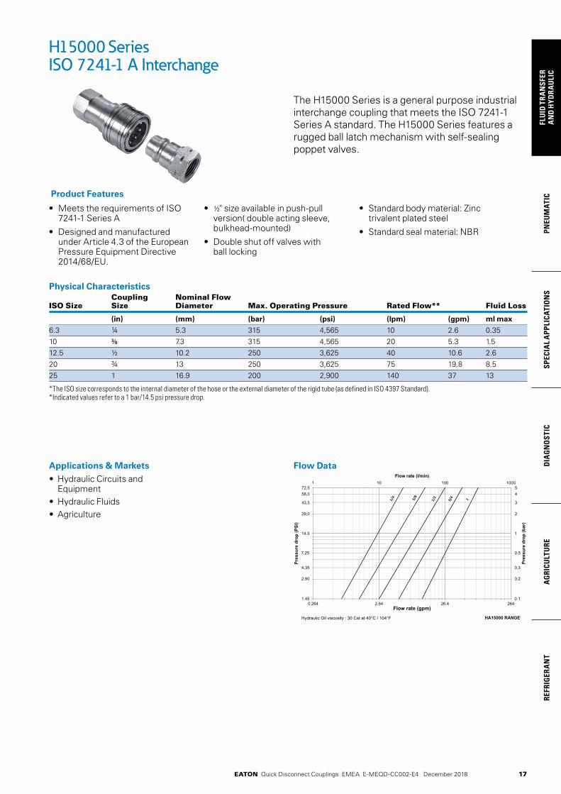
The H15000 Series is a general purpose industrial interchange coupling that meets the ISO 7241-1 Series A standard. The H15000 Series features a rugged ball latch mechanism with self-sealing poppet valves.
• Meets the requirements of ISO 7241-1 Series A
• Designed and manufactured under Article 4.3 of the European Pressure Equipment Directive 2014/68/EU.
• ½" size available in push-pull version( double acting sleeve, bulkhead-mounted)
• Double shut off valves with ball locking
• Standard body material: Zinc trivalent plated steel
• Standard seal material: NBR
Product Features
H15000 SeriesISO 7241-1 A Interchange
Physical Characteristics Coupling Nominal Flow ISO Size Size Diameter Max. Operating Pressure Rated Flow** Fluid Loss
(in) (mm) (bar) (psi) (lpm) (gpm) ml max
6.3 ¼ 5.3 315 4,565 10 2.6 0.3510 3/8 7.3 315 4,565 20 5.3 1.512.5 ½ 10.2 250 3,625 40 10.6 2.620 ¾ 13 250 3,625 75 19.8 8.525 1 16.9 200 2,900 140 37 13
*The ISO size corresponds to the internal diameter of the hose or the external diameter of the rigid tube (as defined in ISO 4397 Standard). *Indicated values refer to a 1 bar/14.5 psi pressure drop.
Applications & Markets• Hydraulic Circuits and
Equipment • Hydraulic Fluids • Agriculture
Flow Data
Hydraulic Oil viscosity : 30 Cst at 40°C / 104°F
4624.6246.2462.01.45
14.5
0.1
1
0001001011
Flow rate (gpm)
Pres
sure
dro
p (P
SI)
Pres
sure
dro
p (b
ar)
Flow rate (l/min)
HA15000 RANGE
72,558,0
43,5
29,0
2,90
4,35
7,25
54
3
2
0,2
0,3
0,5

18
FLUID
TRAN
SFERA
ND
HYD
RAU
LICPN
EUM
ATICSPECIA
L APPLICATIO
NS
DIA
GN
OSTIC
AG
RICULTU
REREFRIG
ERAN
T
EATON Quick Disconnect Couplings EMEA E-MEQD-CC002-E4 December 2018
Part Nominal Flow Coupling Thread Dimensions Number Diameter ISO Size Type Size Fig. A B Hex Weight
(mm) (mm) (in) (mm) (mm) (mm) (g)
HA1501100 5.3 6.3 ¼ Socket/Female G ¼ 1 48 25 19 94HA1521100 5.3 6.3 ¼ Socket/Female ¼ NPT 1 48 25 19 94HA1502100 7.3 10 3/8 Socket/Female G3/8 1 56 30 23 139HA1522100 7.3 10 3/8 Socket/Female 3/8 NPT 1 56 30 23 139HA1503100 10.2 12.5 ½ Socket/Female G ½ 1 67 38 27 238HA1503600 10.2 12.5 ½ Socket/Female G ½ push-pull 1 67 38 27 238HA1523100 10.2 12.5 ½ Socket/Female ½ NPT 1 67 38 27 238HA1504100 13 20 ¾ Socket/Female G ¾ 1 83 48 35 484HA1524100 13 20 ¾ Socket/Female ¾ NPT 1 83 48 35 484HA1505100 16.9 25 1 Socket/Female G 1 1 98 53 41 670HA1525100 16.9 25 1 Socket/Female 1 NPT 1 98 53 41 670Part Nominal Flow Coupling Thread Dimensions Number Diameter ISO Size Type Size Fig. C D E Hex Weight
(mm) (mm) (in) (mm) (mm) (mm) (mm) (g)
HA1501200 5.3 6.3 ¼ Plug/Male G ¼ 2 36 11.8 20 19 36HA1521200 5.3 6.3 ¼ Plug/Male ¼ NPT 2 36 11.8 20 19 36HA1502200 7.3 10 3/8 Plug/Male G3/8 2 41.5 17.3 20 23 62HA1522200 7.3 10 3/8 Plug/Male 3/8 NPT 2 41.5 17.3 20 23 62HA1503200 10.2 12.5 ½ Plug/Male G½ 2 49 20.5 24 27 88HA1523200 10.2 12.5 ½ Plug/Male ½NPT 2 49 20.5 24 27 88HA1504200 13 20 ¾ Plug/Male G ¾ 2 61.5 29.1 23 35 194HA1524200 13 20 ¾ Plug/Male ¾ NPT 2 61.5 29.1 27 35 194HA1505200 16.9 25 1 Plug/Male G 1 2 71.5 34.3 30 41 306HA1525200 16.9 25 1 Plug/Male 1 NPT 2 71.5 34.3 30 41 306
To obtain connected length of coupling, add dimensions A (Fig. 1) and E (Fig. 2) together.
Dust Caps and Dust Plugs Series Dust Plug Dust Cap
6.3 HP1511100 HP151120010 HP1512100 HP151220012.5 HP1513100 HP151320020 HP1514100 HP151420025 HP1515100 HP1515200
Figure 1 Figure 2
H15000 SeriesISO 7241-1 A Interchange
Socket Dust Plug
Plug Dust Cap
Body size Seal & Back-up Ring Kit* Qty
(in) NBR seals & PTFE back-up rings
'1/4 HG 15011 00 50 O-rings + 50 Backup rings'3/8 HG 15021 00 50 O-rings + 50 Backup rings1/2 HG 05031 00 50 O-rings + 50 Backup rings'3/4 HG 15041 00 50 O-rings + 50 Backup rings1 HG 15051 00 50 O-rings + 50 Backup rings*The valve seal is not included in our repair kits
Seal Kit for Servicing Sockets (Female)

19
PNEU
MAT
ICSP
ECIA
L A
PPLI
CATI
ON
SD
IAG
NO
STIC
AG
RICU
LTU
RERE
FRIG
ERA
NT
FLU
ID T
RAN
SFER
AN
D H
YDRA
ULI
C
EATON Quick Disconnect Couplings EMEA E-MEQD-CC002-E4 December 2018
Hydraulic Oil viscosity : 30 Cst at 40°C / 104°F 5600 Series
4624.6246.2462.01.45
14.5
0.1
1
0001001011
Flow rate (gpm)
Pres
sure
dro
p (P
SI)
Pres
sure
dro
p (b
ar)
Flow rate (l/min)
72,558,0
43,5
29,0
2,90
4,35
7,25
54
3
2
0,2
0,3
0,5
Applications & Markets
• Hydraulicandfluidtransfer
• Agriculturalequipment
• Constructionequipment
• Steelmills
• Plantmanufacturingandprocessingequipment
• Dump,snowplow,andmaintenancevehicles
Flow Chart
*Additional sizes are available by request.
TheEaton5600Seriesisaruggedpoppetstyleballlockingquickdisconnectcoupling.AstheoriginalmanufactureroftheISO7241-1Astylecoupling,Eatonhasreinventedthisquickdisconnectcouplingseriestomeetyourapplicationneedsbyofferinganewstainlesssteelconstruction.
Product Features
• Self-sealingpoppetvalveprovidesexcellenthighandlowpressuresealing
• Stainlesssteelconstructionoffersexcellentcorrosionresis-tanceintoughenvironments
• Standardbodymaterial:303stainlesssteel
• Standardsealmaterial:Buna-N.EPDMandFKMsealsareavailableuponrequest
• Availablesizesinclude:5/8",3/4",1"*
• FemaleNPTFthreadends
Eaton®5600SeriesStainlessSteelISO7241-1AProfile
5600 Series (Stainless Steel)ISO 7241-1 A Interchange
• Self-sealing poppet valve provides excellent high and low pressure sealing
• Stainless steel construction offers excellent corrosion resistance in tough environments
• Standard body material: 303 stainless steel
• Standard body material: Buna-N. EPDM and FKM seals are available upon request
• Available sizes include: 5/8, ¾", 1"*
• Female NPTF thread ends*Additional sizes are available upon request.
Product Features
The Eaton 5600 Series is a rugged poppet style ball locking quick disconnect coupling. As the original manufacturer of the ISO 7241-1 A style coupling, Eaton has reinvented this quick disconnect coupling series to meet your application needs by offering a new stainless steel construction.
Applications & Markets• Hydraulic and Fluid
Transfer• Agricultural Equipment• Construction Equipment• Steel Mills• Plant Manufacturing and
Processing Equipment• Dump, Snow Plow,and
Maintenance Vehicles
Flow Data
Physical Characteristics Body Max. Operating Pressure Air Fluid Size Connected Min. Burst Pressure Rated Flow Inclusion Loss
(in) (bar) (psi) (bar) (psi) (lpm) (gpm) cc. max. cc.max.
5/8 207 3,000 621 9,000 45 12 2.8 2.8¾ 207 3,000 621 9,000 106 28 10 8.21 207 3,000 621 9,000 189 50 14.2 14.2
20
FLUID
TRAN
SFERA
ND
HYD
RAU
LICPN
EUM
ATICSPECIA
L APPLICATIO
NS
DIA
GN
OSTIC
AG
RICULTU
REREFRIG
ERAN
T
EATON Quick Disconnect Couplings EMEA E-MEQD-CC002-E4 December 2018
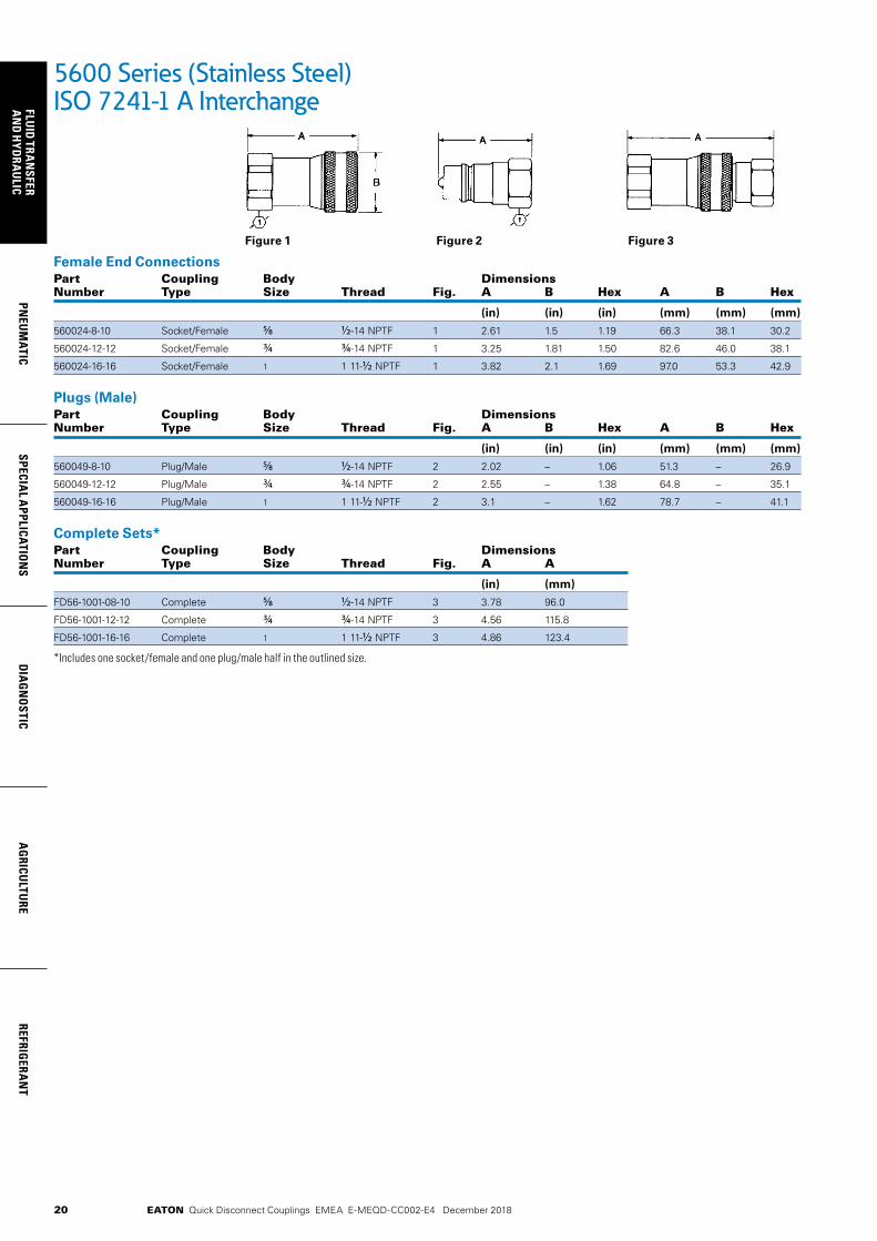
Female End ConnectionsPart Coupling Body Dimensions Number Type Size Thread Fig. A B Hex A B Hex
(in) (in) (in) (mm) (mm) (mm)
560024-8-10 Socket/Female 5/8 1/2-14 NPTF 1 2.61 1.5 1.19 66.3 38.1 30.2
560024-12-12 Socket/Female ¾ ¾-14 NPTF 1 3.25 1.81 1.50 82.6 46.0 38.1
560024-16-16 Socket/Female 1 1 11-1/2 NPTF 1 3.82 2.1 1.69 97.0 53.3 42.9
Plugs (Male)Part Coupling Body Dimensions Number Type Size Thread Fig. A B Hex A B Hex
(in) (in) (in) (mm) (mm) (mm)
560049-8-10 Plug/Male 5/8 1/2-14 NPTF 2 2.02 – 1.06 51.3 – 26.9
560049-12-12 Plug/Male ¾ ¾-14 NPTF 2 2.55 – 1.38 64.8 – 35.1
560049-16-16 Plug/Male 1 1 11-1/2 NPTF 2 3.1 – 1.62 78.7 – 41.1
Complete Sets*Part Coupling Body Dimensions Number Type Size Thread Fig. A A
(in) (mm)
FD56-1001-08-10 Complete 5/8 1/2-14 NPTF 3 3.78 96.0
FD56-1001-12-12 Complete ¾ ¾-14 NPTF 3 4.56 115.8
FD56-1001-16-16 Complete 1 1 11-1/2 NPTF 3 4.86 123.4
*Includes one socket/female and one plug/male half in the outlined size.
5600 Series (Stainless Steel)ISO 7241-1 A Interchange
Figure 2Figure 1 Figure 3
EatonHydraulicsGroupUSA14615LoneOakRoadEdenPrairie,MN55344USATel:952-937-9800Fax:952-294-7722www.eaton.com/hydraulics
EatonHydraulicsBusinessEuropeRoutedelaLongeraie71110MorgesSwitzerlandTel:+41(0)218114600Fax:+41(0)218114601
EatonHydraulicsGroupAsiaPacificEatonBuildingNo.7Lane280LinhongRoadChangningDistrict,Shanghai200335ChinaTel:(+8621)52000099Fax:(+8621)22307240
©2013EatonAllRightsReservedPrintedinUSADocumentNo.E-MEQD-BB003-ESeptember2013
Part Number Coupling Type Body Size Thread Fig. A (in) B (in) Hex (in) A (mm) B (mm) Hex (mm)
560024-8-10 Socket/Female 5/8" 1/2-14NPTF 1 2.61 1.5 1.19 66.3 38.1 30.2
560024-12-12 Socket/Female 3/4" 3/4-14NPTF 1 3.25 1.81 1.50 82.6 46.0 38.1
560024-16-16 Socket/Female 1" 1-111/2NPTF 1 3.82 2.1 1.69 97.0 53.3 42.9
Part Number Coupling Type Body Size Thread Fig. A (in) B (in) Hex (in) A (mm) B (mm) Hex (mm)
560049-8-10 Plug/Male 5/8" 1/2-14NPTF 2 2.02 - 1.06 51.3 - 26.9
560049-12-12 Plug/Male 3/4" 3/4-14NPTF 2 2.55 - 1.38 64.8 - 35.1
560049-16-16 Plug/Male 1" 1-111/2NPTF 2 3.1 - 1.62 78.7 - 41.1
Part Number Coupling Type Body Size Thread Figure A (in) A (mm)
FD56-1001-08-10 Complete 5/8" 1/2-14NPTF 3 3.78 96.0
FD56-1001-12-12 Complete 3/4" 3/4-14NPTF 3 4.56 115.8
FD56-1001-16-16 Complete 1" 1-111/2NPTF 3 4.86 123.4
Dimensions
Dimensions
Dimensions
Female End Connections
Figure 1 Figure 2 Figure 3
Sockets/Females
Plugs/Males
Complete Sets*
*Includes one Socket/Female and one Plug/Male half in the outlined size
Body Size
Max. Operating Pressure
Connected Min. Burst Pressure Rated Flow Air Inclusion Fluid Loss
bar psi bar psi Ipm gpm cc. max cc. max
5/8" 207 3,000 621 9,000 45 12 2.8 2.8
3/4" 207 3,000 621 9,000 106 28 10 8.2
1" 207 3,000 621 9,000 189 50 14.2 14.2
Physical Characteristics
21
PNEU
MAT
ICSP
ECIA
L A
PPLI
CATI
ON
SD
IAG
NO
STIC
AG
RICU
LTU
RERE
FRIG
ERA
NT
FLU
ID T
RAN
SFER
AN
D H
YDRA
ULI
C
EATON Quick Disconnect Couplings EMEA E-MEQD-CC002-E4 December 2018
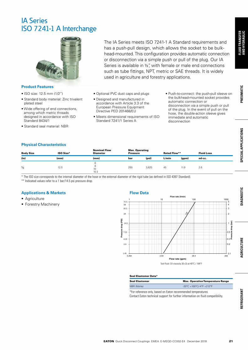
The IA Series meets ISO 7241-1 A Standard requirements and has a push-pull design, which allows the socket to be bulk-head-mounted. This configuration provides automatic connection or disconnection via a simple push or pull of the plug. Our IA Series is available in 1/2”, with female or male end connections such as tube fittings, NPT, metric or SAE threads. It is widely used in agriculture and forestry applications.
• ISO size: 12.5 mm (1/2”)
• Standard body material: Zinc trivalent plated steel
• Wide offering of end connections, among which metric threads designed in accordance with ISO Standard 8434/1
• Standard seal material: NBR
• Optional PVC dust caps and plugs
• Designed and manufactured in accordance with Article 3.3 of the European Pressure Equipment Directive PED 201468/EU
• Meets dimensional requirements of ISO Standard 7241/1 Series A
• Push-to-connect: the push-pull sleeve on the bulkhead-mounted socket provides automatic connection or disconnection via a simple push or pull of the plug. In the event of pull on the hose, the double-action sleeve gives immediate and automatic disconnection
Product Features
IA SeriesISO 7241-1 A Interchange
Applications & Markets• Agriculture • Forestry Machinery
Physical Characteristics
Body Size ISO Size*Nominal Flow Diameter
Max. Operating Pressure Rated Flow** Fluid Loss
(in) (mm) (mm) bar (psi) L /min (gpm) ml-cc.
1/2 12.5
68
1010.3
250 3,625 45 11.9 2.6
* The ISO size corresponds to the internal diameter of the hose or the external diameter of the rigid tube (as defined in ISO 4397 Standard).** Indicated values refer to a 1 bar/14.5 psi pressure drop.
Seal Elastomer Data*
Seal Elastomer Max. Operation Temperature Range
NBR (Nitrile) -20°C +100°C/-4°F +212°F
*For reference only, based on Eaton recommended temperatures.Contact Eaton technical support for further information on fluid compatibility.
0.264 2.64 26.4 0.1
1
0.5
0.3
0.2
54
3
1 10 100 1000
Flow rate (gpm)
Pres
sure
dro
p (P
SI)
Pres
sure
dro
p (b
ar)
Flow rate (l/min)
72.5
1.45
14.5
43.5
4.35
7.25
58
29
2.9
2
264
1/2
Test Fluid: Oil viscosity 30 cSt at 40°C / 104°F
Flow Data
22
FLUID
TRAN
SFERA
ND
HYD
RAU
LICPN
EUM
ATICSPECIA
L APPLICATIO
NS
DIA
GN
OSTIC
AG
RICULTU
REREFRIG
ERAN
T
EATON Quick Disconnect Couplings EMEA E-MEQD-CC002-E4 December 2018
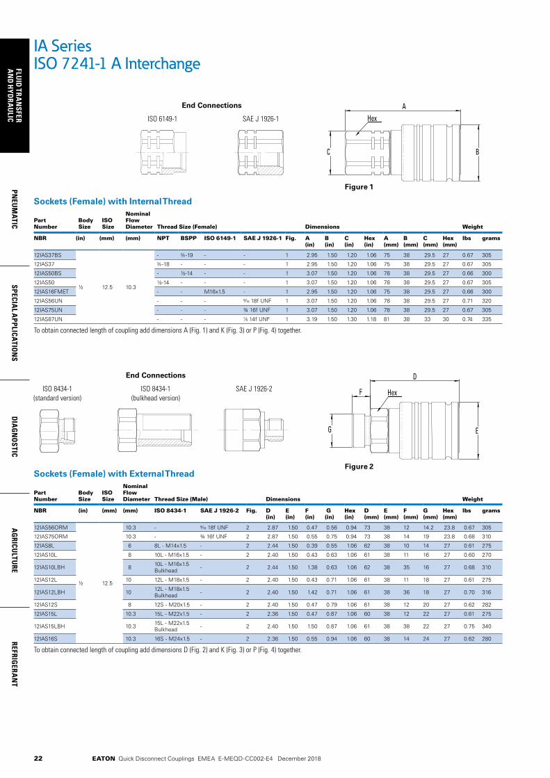
IA SeriesISO 7241-1 A Interchange
Sockets (Female) with Internal Thread
Part Number
Body Size
ISOSize
Nominal Flow Diameter Thread Size (Female) Dimensions Weight
NBR (in) (mm) (mm) NPT BSPP ISO 6149-1 SAE J 1926-1 Fig. A (in)
B (in)
C (in)
Hex (in)
A (mm)
B (mm)
C (mm)
Hex (mm)
lbs grams
12IAS37BS
½ 12.5 10.3
- -19 - - 1 2.95 1.50 1.20 1.06 75 38 29.5 27 0.67 305
12IAS37 -18 - - - 1 2.95 1.50 1.20 1.06 75 38 29.5 27 0.67 305
12IAS50BS - ½-14 - - 1 3.07 1.50 1.20 1.06 78 38 29.5 27 0.66 300
12IAS50 ½-14 - - - 1 3.07 1.50 1.20 1.06 78 38 29.5 27 0.67 305
12IAS16FMET - - M16x1.5 - 1 2.95 1.50 1.20 1.06 75 38 29.5 27 0.66 300
12IAS56UN - - - 18f UNF 1 3.07 1.50 1.20 1.06 78 38 29.5 27 0.71 320
12IAS75UN - - - ¾ 16f UNF 1 3.07 1.50 1.20 1.06 78 38 29.5 27 0.67 305
12IAS87UN - - - 14f UNF 1 3.19 1.50 1.30 1.18 81 38 33 30 0.74 335
To obtain connected length of coupling add dimensions A (Fig. 1) and K (Fig. 3) or P (Fig. 4) together.
Sockets (Female) with External Thread
Part Number
Body Size
ISOSize
Nominal Flow Diameter Thread Size (Male) Dimensions Weight
NBR (in) (mm) (mm) ISO 8434-1 SAE J 1926-2 Fig. D (in)
E (in)
F (in)
G (in)
Hex (in)
D (mm)
E (mm)
F (mm)
G (mm)
Hex (mm)
lbs grams
12IAS56ORM
½ 12.5
10.3 - 18f UNF 2 2.87 1.50 0.47 0.56 0.94 73 38 12 14.2 23.8 0.67 305
12IAS75ORM 10.3 - ¾ 16f UNF 2 2.87 1.50 0.55 0.75 0.94 73 38 14 19 23.8 0.68 310
12IAS8L 6 8L - M14x1.5 - 2 2.44 1.50 0.39 0.55 1.06 62 38 10 14 27 0.61 275
12IAS10L 8 10L - M16x1.5 - 2 2.40 1.50 0.43 0.63 1.06 61 38 11 16 27 0.60 270
12IAS10LBH 8 10L - M16x1.5 Bulkhead - 2 2.44 1.50 1.38 0.63 1.06 62 38 35 16 27 0.68 310
12IAS12L 10 12L - M18x1.5 - 2 2.40 1.50 0.43 0.71 1.06 61 38 11 18 27 0.61 275
12IAS12LBH 10 12L - M18x1.5 Bulkhead - 2 2.40 1.50 1.42 0.71 1.06 61 38 36 18 27 0.70 316
12IAS12S 8 12S - M20x1.5 - 2 2.40 1.50 0.47 0.79 1.06 61 38 12 20 27 0.62 282
12IAS15L 10.3 15L - M22x1.5 - 2 2.36 1.50 0.47 0.87 1.06 60 38 12 22 27 0.61 275
12IAS15LBH 10.3 15L - M22x1.5 Bulkhead - 2 2.40 1.50 1.50 0.87 1.06 61 38 38 22 27 0.75 340
12IAS16S 10.3 16S - M24x1.5 - 2 2.36 1.50 0.55 0.94 1.06 60 38 14 24 27 0.62 280
To obtain connected length of coupling add dimensions D (Fig. 2) and K (Fig. 3) or P (Fig. 4) together.
End Connections
ISO 6149-1 SAE J 1926-1
A
BC
Hex
End Connections
ISO 8434-1 (standard version)
ISO 8434-1 (bulkhead version)
SAE J 1926-2
EG
F
D
Hex
Figure 1
Figure 2

23
PNEU
MAT
ICSP
ECIA
L A
PPLI
CATI
ON
SD
IAG
NO
STIC
AG
RICU
LTU
RERE
FRIG
ERA
NT
FLU
ID T
RAN
SFER
AN
D H
YDRA
ULI
C
EATON Quick Disconnect Couplings EMEA E-MEQD-CC002-E4 December 2018
Plugs (Male) with Internal Thread
Part Number
Body Size
ISOSize
Nominal Flow Diameter Thread Size (Female) Dimensions Weight
NBR (in) (mm) (mm) NPT BSPP ISO 6149-1 SAE J 1926-1 Fig. H (in)
I (in)
J (in)
K (in)
Hex (in)
H (mm)
I (mm)
J (mm)
K (mm)
Hex (mm)
lbs grams
12IAP37BS
½ 12.5 10.3
- -19 - - 3 2.24 0.84 1.20 1.22 1.06 57 20.5 29.5 31 27 0.28 125
12IAP37 -18 - - - 3 2.24 0.84 1.20 1.22 1.06 57 20.5 29.5 31 27 0.29 130
12IAP50BS - ½-14 - - 3 2.36 0.84 1.20 1.34 1.06 60 20.5 29.5 34 27 0.28 125
12IAP50 ½-14 - - - 3 2.36 0.84 1.20 1.34 1.06 60 20.5 29.5 34 27 0.28 125
12IAP16FMET - - M16x1.5 - 3 2.24 0.84 1.20 1.22 1.06 57 20.5 29.5 31 27 0.26 120
12IAP56UN - - - 18f UNF 3 2.36 0.84 1.20 1.34 1.06 60 20.5 29.5 34 27 0.31 140
12IAP75UN - - - ¾ 16f UNF 3 2.36 0.84 1.20 1.34 1.06 60 20.5 29.5 34 27 0.28 125
12IAP87UN - - - 14f UNF 3 2.48 0.84 1.30 1.46 1.18 63 20.5 33 37 30 0.34 155
To obtain connected length of coupling add dimensions K (Fig. 3) and A (Fig. 1) or D (Fig. 2) together.
IA SeriesISO 7241-1 A Interchange
Dust Plugs and Dust CapsBody Size Socket Dust Plug Part Number Plug Dust Cap Part Number
(in) Plastic Plastic
½ HP1513100 HP1513200
Plug Dust Cap
Socket Dust Cap
End Connections
ISO 6149-1 SAE J 1926-1 K
I J
H
Hex
Fig. 3
End Connections
ISO 8434-1 (standard version)
ISO 8434-1 (bulkhead version)
SAE J 1926-2P M
N O
L
Hex
Fig. 4
Plugs (Male) with External Thread
Part Number
Body Size
ISOSize
Nominal Flow Diameter Thread Size (Male) Dimensions Weight
NBR (in) (mm) (mm) ISO 8434-1 SAE J 1926-2 Fig. L (in)
M (in)
N (in)
O (in)
P (in)
Hex (in)
L (mm)
M (mm)
N (mm)
O (mm)
P (mm)
Hex (mm)
lbs grams
12IAP56ORM
½ 12.5
10.3 - 18f UNF 4 2.20 0.47 0.84 0.56 1.18 0.94 56 12 20.5 14.2 30 23.8 0.28 125
12IAP75ORM 10.3 - ¾ 16f UNF 4 2.20 0.55 0.84 0.75 1.18 0.94 56 14 20.5 19 30 23.8 0.29 130
12IAP8L 6 8L - M14x1.5 - 4 1.75 0.39 0.84 0.55 0.71 1.06 44.5 10 20.5 14 18 27 0.21 95
12IAP10L 8 10L - M16x1.5 - 4 1.71 0.43 0.84 0.63 0.67 1.06 43.5 11 20.5 16 17 27 0.21 95
12IAP10LBH 8 10L - M16x1.5 Bulkhead - 4 1.75 1.38 0.84 0.63 0.71 1.06 44.5 35 20.5 16 18 27 0.30 135
12IAP12L 10 12L - M18x1.5 - 4 1.71 0.43 0.84 0.71 0.67 1.06 43.5 11 20.5 18 17 27 0.21 95
12IAP12LBH 10 12L - M18x1.5 Bulkhead - 4 1.71 1.42 0.84 0.71 0.67 1.06 43.5 36 20.5 18 17 27 0.30 136
12IAP12S 8 12S - M20x1.5 - 4 1.71 0.47 0.84 0.79 0.67 1.06 43.5 12 20.5 20 17 27 0.22 102
12IAP15L 10.3 15L - M22x1.5 - 4 1.67 0.47 0.84 0.87 0.63 1.06 42.5 12 20.5 22 16 27 0.21 95
12IAP15LBH 10.3 15L - M22x1.5 Bulkhead - 4 1.71 1.50 0.84 0.87 0.67 1.06 43.5 38 20.5 22 17 27 0.35 160
12IAP16S 10.3 16S - M24x1.5 - 4 1.67 0.55 0.84 0.94 0.63 1.06 42.5 14 20.5 24 16 27 0.22 100
To obtain connected length of coupling add dimensions P (Fig. 4) and A (Fig. 1) or D (Fig. 2) together.

24
FLUID
TRAN
SFERA
ND
HYD
RAU
LICPN
EUM
ATICSPECIA
L APPLICATIO
NS
DIA
GN
OSTIC
AG
RICULTU
REREFRIG
ERAN
T
EATON Quick Disconnect Couplings EMEA E-MEQD-CC002-E4 December 2018
Physical Characteristics
Body SizeNominal Flow Diameter
Max. Operating Pressure* Non hazardous liquids & gases in Group 2
Hazardous liquids & gases in Group 1 Rated Flow**
Fluid Loss
(in) (mm) (bar) (psi) (bar) (psi) (lpm) (gpm) ml-cc.
3.8 1,000 14,500 1,000 14,500 6.1 1.61 0.4
¼ 5.7 700 10,150 700 10,150 11.6 3.06 1
7.6 600 8,700 600 8,700 16.7 4.41 2
½ 10.3 500 7,250 500 7,250 25.5 6.74 2.5
¾ 14.2 400 5,800 400 5,800 55 14.53 5.5
1 16.5 300 4,350 300 4,350 87 22.98 9
1¼ 20.5 200 2,900 200 2,900 140 36.98 23
1½ 25.8 150 2,175 38 550 208 54.95 36
2 34.7 100 1,450 28 405 357 94.3 70
* For pulsating pressures when disconnected apply a multiplier of 0.5** Indicated values refer to a 1 bar/14.5 psi pressure drop.
H5000 Series (Steel)
• Proprietary profile• Pull-to-connect with double shut-off
valving• Ball-locking• Optional safety sleeve lock prevents
accidental disconnections
• Optional dust caps and plugs (made of anodized aluminum)
• Pressure performance• Standard body material: Zinc
trivalent steel• Standard seal material: NBR, FKM,
EPDM
• The heat treatment of the plug and use of high strength steel for the socket sleeve provide superior mechanical and hydraulic performance The design of the valve gives the coupling increased robustness when disconnected.
Product Features
Eaton’s H5000 Series steel quick disconnect coupling is a pull to connect double shut-off coupling. Featuring the original Eaton’s Gromelle™ profile, it remains as the series users prefer when it comes to severe hydraulic applications such as high pressure, pressure impulses, heavy mechanical loads and frequent connection and disconnection cycles. The unique sleeve lock option offers a reliable solution and benefit to the end user when safety is a concern.
Seal Elastomer Data*
Seal Elastomer Max. Operation Temperature Range
NBR (Nitrile) -20°C +100°C/-4°F +212°F
FKM -20°C +200°C/-4°F +392°F
EPDM (Ethylene-Propylene)** -40°C +150°C/-40°F +302°F
* For reference only, based on Eaton recommended temperatures.** In accordance with NF L 17-241 or NAS 1613 rev. 5Contact Eaton technical support for further information on fluid compatibility.
Couplings with nominal diameters up to and including 25 mm are designed and manufactured under Article 4.3 of the European Pressure Equipment Directive 2014/68/EU. Couplings with nominal diameters greater than 25 mm are designed and manufactured in accordance with the stipulations of Module A of the European Pressure Equipment Directive 2014/68/EU. They should not be used to convey unstable gases.Group 1 = Hazardous media / Group 2 = Other media
European Pressure Equipment Directive
Applications & Markets• Automobile• Agriculture• Construction• Oil and Gas• Railway
• Aeronautics• Food Processing • Iron and Steel
Industry• Electronics• Laboratories• General Hydraulic
Applications
0.264 2.64 26.4 0.1
1
0.5
0.3
0.2
54
3
1 10 100 1000
Flow Rate (gpm)
Pre
ssu
re d
rop
(P
SI)
Pre
ssu
re d
rop
(b
ar)
Flow Rate (l/min)
72.5
1.45
14.5
43.5
4.35
7.25
58
29
2.9
2
264
1/8
1/4
3/8
1/2
3/4
1" 1" 1
/4
1" 1
/2
2"
Test Fluid: Oil viscosity 30 cSt at 40°C/104°F
Flow Data
25
PNEU
MAT
ICSP
ECIA
L A
PPLI
CATI
ON
SD
IAG
NO
STIC
AG
RICU
LTU
RERE
FRIG
ERA
NT
FLU
ID T
RAN
SFER
AN
D H
YDRA
ULI
C
EATON Quick Disconnect Couplings EMEA E-MEQD-CC002-E4 December 2018
Sockets with Sleeve Lock (Female)
Part NumberBody Size
Nominal Flow Diameter Thread Size** (Female) Dimensions Weight
NBR* FKM EPDM (in) (mm) NPT BSPP Metric Fig. D (in)
E (in)
F (in)
Across flats (in)
D (mm)
E (mm)
F (mm)
Across flats (mm)
lbs grams
HA0500300 HA05003V0 HA05003E0 3.8 - -28 - 2 1.65 0.94 0.83 0.63 42 24 21 16 0.19 91
HA0520300 HA05203V0 HA05203E0 3.8 -27 - - 2 1.65 0.94 0.83 0.63 42 24 21 16 0.19 91
HA0530300 HA05303V0 HA05303E0 3.8 - - M10x100 2 1.65 0.94 0.83 0.63 42 24 21 16 0.19 91
HA0501300 HA05013V0 HA05013E0 ¼ 5.7 - ¼-19 - 2 1.97 1.10 0.94 0.75 50 28 24 19 0.27 134
HA0521300 HA05213V0 HA05213E0 ¼ 5.7 ¼-18 - - 2 1.97 1.10 0.94 0.75 50 28 24 19 0.27 134
HA0531300 HA05313V0 HA05313E0 ¼ 5.7 - - M14x150 2 1.97 1.10 0.94 0.75 50 28 24 19 0.27 134
HA0502300 HA05023V0 HA05023E0 7.6 - -19 - 2 2.32 1.34 1.10 0.90 59 34 28 23 0.43 225
HA0522300 HA05223V0 HA05223E0 7.6 -18 - - 2 2.32 1.34 1.10 0.90 59 34 28 23 0.43 225
HA0532300 HA05323V0 HA05323E0 7.6 - - M18x150 2 2.32 1.34 1.10 0.90 59 34 28 23 0.43 225
HA0503300 HA05033V0 HA05033E0 ½ 10.3 - ½-14 - 2 2.71 1.50 1.22 1.06 69 38 31 27 0.50 310
HA0523300 HA05233V0 HA05233E0 ½ 10.3 ½-14 - - 2 2.71 1.50 1.22 1.06 69 38 31 27 0.50 310
HA0533300 HA05333V0 HA05333E0 ½ 10.3 - - M22x150 2 2.71 1.50 1.22 1.06 69 38 31 27 0.50 310
HA0504300 HA05043V0 HA05043E0 ¾ 14.2 - ¾-14 - 2 3.50 1.89 1.57 1.38 89 48 40 35 1.27 665
HA0524300 HA05243V0 HA05243E0 ¾ 14.2 ¾-14 - - 2 3.50 1.89 1.57 1.38 89 48 40 35 1.27 665
HA0534300 HA05343V0 HA05343E0 ¾ 14.2 - - M27x150 2 3.50 1.89 1.57 1.38 89 48 40 35 1.27 665
HA0505300 HA05053V0 HA05053E0 1 16.5 - 1-11 - 2 3.89 2.05 1.77 1.61 99 52 45 41 1.59 813
HA0525300 HA05253V0 HA05253E0 1 16.5 1-11½ - - 2 3.89 2.05 1.77 1.61 99 52 45 41 1.59 813
- HA05063V0 HA05063E0 1¼ 20.5 - 1¼-11 - 2 5.20 2.95 2.44 2.16 132 75 62 55 4.77 2,230
- HA05073V0 HA05073E0 1½ 25.8 - 1½-11 - 2 5.90 3.35 2.95 2.56 150 85 75 65 7.72 3,585
- HA05093V0 HA05093E0 2 34.7 - 2-11 - 2 6.69 3.82 3.35 2.95 170 97 85 75 10.67 5,658
* Body sizes 1¼, 1½ and 2 are supplied with FKM seals as a standard.** Alternative end connections available upon request.To obtain connected length of coupling add dimensions D (Fig. 2) and J (Fig. 3) together.
H5000 Series (Steel)
Sockets (Female)
Part NumberBody Size
Nominal Flow Diameter Thread Size** (Female) Dimensions Weight
NBR* FKM EPDM (in) (mm) NPT BSPP Metric Fig. A (in)
B (in)
C (in)
Across flats (in)
A (mm)
B (mm)
C (mm)
Across flats (mm)
lbs grams
HA0500100 HA05001V0 HA05001E0 3.8 - -28 - 1 1.65 0.94 0.83 0.63 42 24 21 16 0.19 88
HA0520100 HA05201V0 HA05201E0 3.8 -27 - - 1 1.65 0.94 0.83 0.63 42 24 21 16 0.19 88
HA0530100 HA05301V0 HA05301E0 3.8 - - M10x100 1 1.65 0.94 0.83 0.63 42 24 21 16 0.19 88
HA0501100 HA05011V0 HA05011E0 ¼ 5.7 - ¼-19 - 1 1.97 1.10 0.94 0.75 50 28 24 19 0.27 122
HA0521100 HA05211V0 HA05211E0 ¼ 5.7 ¼-18 - - 1 1.97 1.10 0.94 0.75 50 28 24 19 0.27 122
HA0531100 HA05311V0 HA05311E0 ¼ 5.7 - - M14x150 1 1.97 1.10 0.94 0.75 50 28 24 19 0.27 122
HA0502100 HA05021V0 HA05021E0 7.6 - -19 - 1 2.32 1.34 1.10 0.90 59 34 28 23 0.43 197
HA0522100 HA05221V0 HA05221E0 7.6 -18 - - 1 2.32 1.34 1.10 0.90 59 34 28 23 0.43 197
HA0532100 HA05321V0 HA05321E0 7.6 - - M18x150 1 2.32 1.34 1.10 0.90 59 34 28 23 0.43 197
HA0503100 HA05031V0 HA05031E0 ½ 10.3 - ½-14 - 1 2.71 1.50 1.22 1.06 69 38 31 27 0.50 226
HA0523100 HA05231V0 HA05231E0 ½ 10.3 ½-14 - - 1 2.71 1.50 1.22 1.06 69 38 31 27 0.50 226
HA0533100 HA05331V0 HA05331E0 ½ 10.3 - - M22x150 1 2.71 1.50 1.22 1.06 69 38 31 27 0.50 226
HA0504100 HA05041V0 HA05041E0 ¾ 14.2 - ¾-14 - 1 3.50 1.89 1.57 1.38 89 48 40 35 1.27 577
HA0524100 HA05241V0 HA05241E0 ¾ 14.2 ¾-14 - - 1 3.50 1.89 1.57 1.38 89 48 40 35 1.27 577
HA0534100 HA05341V0 HA05341E0 ¾ 14.2 - - M27x150 1 3.50 1.89 1.57 1.38 89 48 40 35 1.27 577
HA0505100 HA05051V0 HA05051E0 1 16.5 - 1-11 - 1 3.89 2.05 1.77 1.61 99 52 45 41 1.59 720
HA0525100 HA05251V0 HA05251E0 1 16.5 1-11½ - - 1 3.89 2.05 1.77 1.61 99 52 45 41 1.59 720
- HA05061V0 HA05061E0 1¼ 20.5 - 1¼-11 - 1 5.20 2.95 2.44 2.16 132 75 62 55 4.77 2,165
- HA05071V0 HA05071E0 1½ 25.8 - 1½-11 - 1 5.90 3.35 2.95 2.56 150 85 75 65 7.72 3,500
- HA05091V0 HA05091E0 2 34.7 - 2-11 - 1 6.69 3.82 3.35 2.95 170 97 85 75 10.67 4,840
* Body sizes 1¼, 1½ and 2 are supplied with FKM seals as a standard.** Alternative end connections available upon request.To obtain connected length of coupling add dimensions A (Fig. 1) and J (Fig. 3) together.
A
C B
Across flats
Across flats
D
EF Figure 2
Figure 1
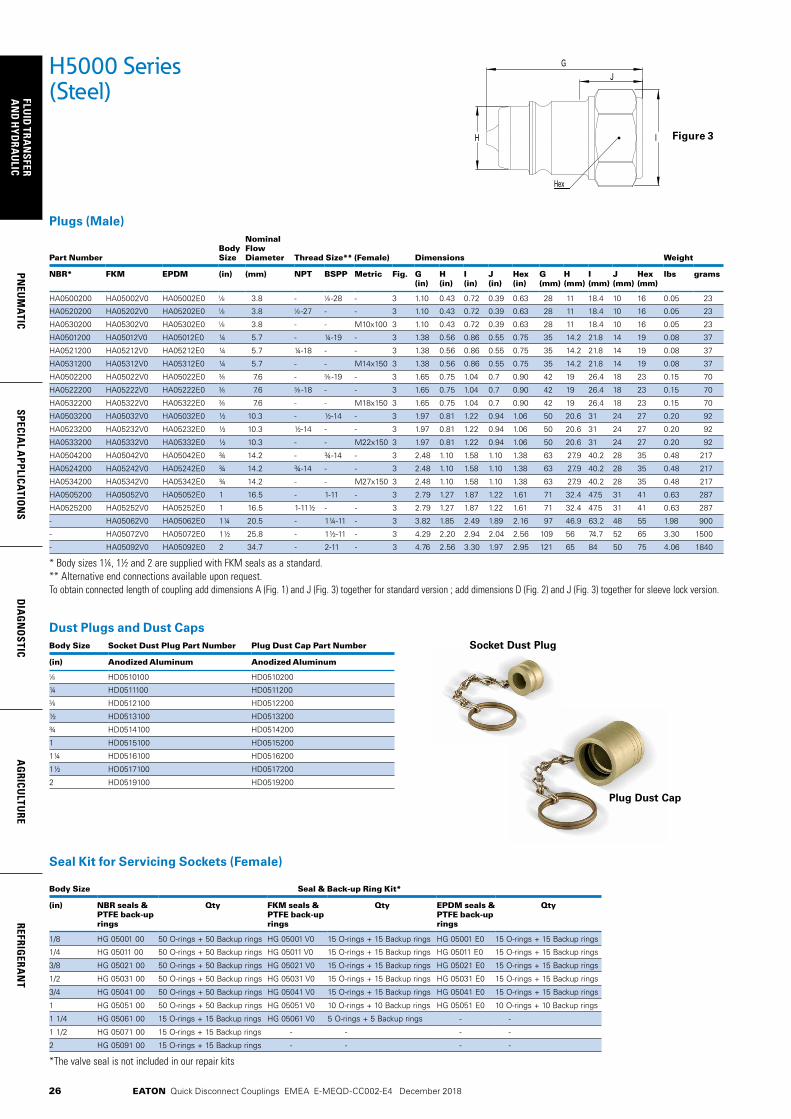
26
FLUID
TRAN
SFERA
ND
HYD
RAU
LICPN
EUM
ATICSPECIA
L APPLICATIO
NS
DIA
GN
OSTIC
AG
RICULTU
REREFRIG
ERAN
T
EATON Quick Disconnect Couplings EMEA E-MEQD-CC002-E4 December 2018
Plugs (Male)
Part NumberBody Size
Nominal Flow Diameter Thread Size** (Female) Dimensions Weight
NBR* FKM EPDM (in) (mm) NPT BSPP Metric Fig. G (in)
H (in)
I (in)
J (in)
Hex (in)
G (mm)
H (mm)
I (mm)
J (mm)
Hex (mm)
lbs grams
HA0500200 HA05002V0 HA05002E0 3.8 - -28 - 3 1.10 0.43 0.72 0.39 0.63 28 11 18.4 10 16 0.05 23
HA0520200 HA05202V0 HA05202E0 3.8 -27 - - 3 1.10 0.43 0.72 0.39 0.63 28 11 18.4 10 16 0.05 23
HA0530200 HA05302V0 HA05302E0 3.8 - - M10x100 3 1.10 0.43 0.72 0.39 0.63 28 11 18.4 10 16 0.05 23
HA0501200 HA05012V0 HA05012E0 ¼ 5.7 - ¼-19 - 3 1.38 0.56 0.86 0.55 0.75 35 14.2 21.8 14 19 0.08 37
HA0521200 HA05212V0 HA05212E0 ¼ 5.7 ¼-18 - - 3 1.38 0.56 0.86 0.55 0.75 35 14.2 21.8 14 19 0.08 37
HA0531200 HA05312V0 HA05312E0 ¼ 5.7 - - M14x150 3 1.38 0.56 0.86 0.55 0.75 35 14.2 21.8 14 19 0.08 37
HA0502200 HA05022V0 HA05022E0 7.6 - -19 - 3 1.65 0.75 1.04 0.7 0.90 42 19 26.4 18 23 0.15 70
HA0522200 HA05222V0 HA05222E0 7.6 -18 - - 3 1.65 0.75 1.04 0.7 0.90 42 19 26.4 18 23 0.15 70
HA0532200 HA05322V0 HA05322E0 7.6 - - M18x150 3 1.65 0.75 1.04 0.7 0.90 42 19 26.4 18 23 0.15 70
HA0503200 HA05032V0 HA05032E0 ½ 10.3 - ½-14 - 3 1.97 0.81 1.22 0.94 1.06 50 20.6 31 24 27 0.20 92
HA0523200 HA05232V0 HA05232E0 ½ 10.3 ½-14 - - 3 1.97 0.81 1.22 0.94 1.06 50 20.6 31 24 27 0.20 92
HA0533200 HA05332V0 HA05332E0 ½ 10.3 - - M22x150 3 1.97 0.81 1.22 0.94 1.06 50 20.6 31 24 27 0.20 92
HA0504200 HA05042V0 HA05042E0 ¾ 14.2 - ¾-14 - 3 2.48 1.10 1.58 1.10 1.38 63 27.9 40.2 28 35 0.48 217
HA0524200 HA05242V0 HA05242E0 ¾ 14.2 ¾-14 - - 3 2.48 1.10 1.58 1.10 1.38 63 27.9 40.2 28 35 0.48 217
HA0534200 HA05342V0 HA05342E0 ¾ 14.2 - - M27x150 3 2.48 1.10 1.58 1.10 1.38 63 27.9 40.2 28 35 0.48 217
HA0505200 HA05052V0 HA05052E0 1 16.5 - 1-11 - 3 2.79 1.27 1.87 1.22 1.61 71 32.4 47.5 31 41 0.63 287
HA0525200 HA05252V0 HA05252E0 1 16.5 1-11½ - - 3 2.79 1.27 1.87 1.22 1.61 71 32.4 47.5 31 41 0.63 287
- HA05062V0 HA05062E0 1¼ 20.5 - 1¼-11 - 3 3.82 1.85 2.49 1.89 2.16 97 46.9 63.2 48 55 1.98 900
- HA05072V0 HA05072E0 1½ 25.8 - 1½-11 - 3 4.29 2.20 2.94 2.04 2.56 109 56 74.7 52 65 3.30 1500
- HA05092V0 HA05092E0 2 34.7 - 2-11 - 3 4.76 2.56 3.30 1.97 2.95 121 65 84 50 75 4.06 1840
* Body sizes 1¼, 1½ and 2 are supplied with FKM seals as a standard.** Alternative end connections available upon request.To obtain connected length of coupling add dimensions A (Fig. 1) and J (Fig. 3) together for standard version ; add dimensions D (Fig. 2) and J (Fig. 3) together for sleeve lock version.
H5000 Series (Steel)
JG
H I
Hex
Dust Plugs and Dust CapsBody Size Socket Dust Plug Part Number Plug Dust Cap Part Number
(in) Anodized Aluminum Anodized Aluminum
HD0510100 HD0510200
¼ HD0511100 HD0511200
HD0512100 HD0512200
½ HD0513100 HD0513200
¾ HD0514100 HD0514200
1 HD0515100 HD0515200
1¼ HD0516100 HD0516200
1½ HD0517100 HD0517200
2 HD0519100 HD0519200
Socket Dust Plug
Plug Dust Cap
Figure 3
Seal Kit for Servicing Sockets (Female)
Body Size Seal & Back-up Ring Kit*
(in) NBR seals & PTFE back-up rings
Qty FKM seals & PTFE back-up rings
Qty EPDM seals & PTFE back-up rings
Qty
1/8 HG 05001 00 50 O-rings + 50 Backup rings HG 05001 V0 15 O-rings + 15 Backup rings HG 05001 E0 15 O-rings + 15 Backup rings
1/4 HG 05011 00 50 O-rings + 50 Backup rings HG 05011 V0 15 O-rings + 15 Backup rings HG 05011 E0 15 O-rings + 15 Backup rings
3/8 HG 05021 00 50 O-rings + 50 Backup rings HG 05021 V0 15 O-rings + 15 Backup rings HG 05021 E0 15 O-rings + 15 Backup rings
1/2 HG 05031 00 50 O-rings + 50 Backup rings HG 05031 V0 15 O-rings + 15 Backup rings HG 05031 E0 15 O-rings + 15 Backup rings
3/4 HG 05041 00 50 O-rings + 50 Backup rings HG 05041 V0 15 O-rings + 15 Backup rings HG 05041 E0 15 O-rings + 15 Backup rings
1 HG 05051 00 50 O-rings + 50 Backup rings HG 05051 V0 10 O-rings + 10 Backup rings HG 05051 E0 10 O-rings + 10 Backup rings
1 1/4 HG 05061 00 15 O-rings + 15 Backup rings HG 05061 V0 5 O-rings + 5 Backup rings - -
1 1/2 HG 05071 00 15 O-rings + 15 Backup rings - - - -
2 HG 05091 00 15 O-rings + 15 Backup rings - - - -
*The valve seal is not included in our repair kits
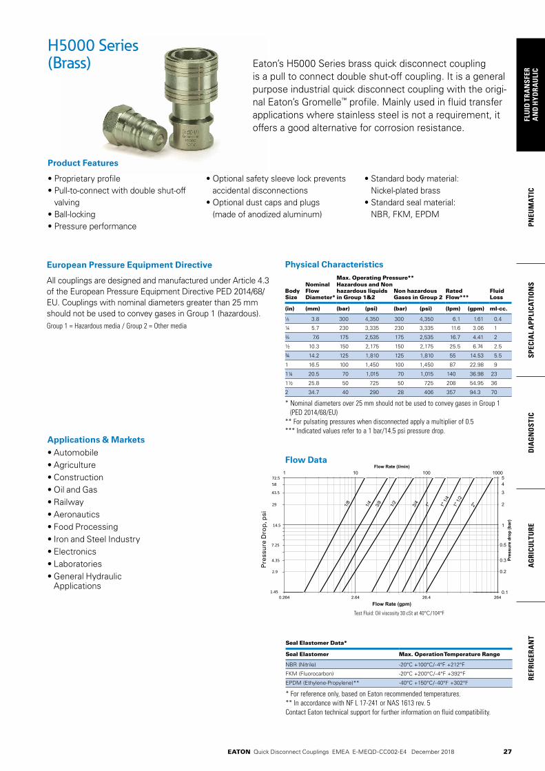
27
PNEU
MAT
ICSP
ECIA
L A
PPLI
CATI
ON
SD
IAG
NO
STIC
AG
RICU
LTU
RERE
FRIG
ERA
NT
FLU
ID T
RAN
SFER
AN
D H
YDRA
ULI
C
EATON Quick Disconnect Couplings EMEA E-MEQD-CC002-E4 December 2018
0.264 2.64 26.4 0.1
1
0.5
0.3
0.2
54
3
1 10 100 1000
Flow Rate (gpm)
Pre
ssu
re d
rop
(P
SI)
Pre
ssu
re d
rop
(b
ar)
Flow Rate (l/min)
72.5
1.45
14.5
43.5
4.35
7.25
58
29
2.9
2
264
1/8
1/4
3/8
1/2
3/4
1" 1" 1
/4
1" 1
/2
2"
Physical Characteristics
Body Size
Nominal Flow Diameter*
Max. Operating Pressure**
Rated Flow***
Fluid Loss
Hazardous and Non hazardous liquids in Group 1&2
Non hazardous Gases in Group 2
(in) (mm) (bar) (psi) (bar) (psi) (lpm) (gpm) ml-cc.
3.8 300 4,350 300 4,350 6.1 1.61 0.4
¼ 5.7 230 3,335 230 3,335 11.6 3.06 1
7.6 175 2,535 175 2,535 16.7 4.41 2
½ 10.3 150 2,175 150 2,175 25.5 6.74 2.5
¾ 14.2 125 1,810 125 1,810 55 14.53 5.5
1 16.5 100 1,450 100 1,450 87 22.98 9
1¼ 20.5 70 1,015 70 1,015 140 36.98 23
1½ 25.8 50 725 50 725 208 54.95 36
2 34.7 40 290 28 406 357 94.3 70
* Nominal diameters over 25 mm should not be used to convey gases in Group 1 (PED 2014/68/EU)
** For pulsating pressures when disconnected apply a multiplier of 0.5*** Indicated values refer to a 1 bar/14.5 psi pressure drop.
H5000 Series(Brass)
• Proprietary profile• Pull-to-connect with double shut-off
valving• Ball-locking• Pressure performance
• Optional safety sleeve lock prevents accidental disconnections
• Optional dust caps and plugs (made of anodized aluminum)
• Standard body material: Nickel-plated brass
• Standard seal material: NBR, FKM, EPDM
Product Features
Eaton’s H5000 Series brass quick disconnect coupling is a pull to connect double shut-off coupling. It is a general purpose industrial quick disconnect coupling with the origi-nal Eaton’s Gromelle™ profile. Mainly used in fluid transfer applications where stainless steel is not a requirement, it offers a good alternative for corrosion resistance.
Seal Elastomer Data*
Seal Elastomer Max. Operation Temperature Range
NBR (Nitrile) -20°C +100°C/-4°F +212°F
FKM (Fluorocarbon) -20°C +200°C/-4°F +392°F
EPDM (Ethylene-Propylene)** -40°C +150°C/-40°F +302°F
* For reference only, based on Eaton recommended temperatures.** In accordance with NF L 17-241 or NAS 1613 rev. 5Contact Eaton technical support for further information on fluid compatibility.
All couplings are designed and manufactured under Article 4.3 of the European Pressure Equipment Directive PED 2014/68/EU. Couplings with nominal diameters greater than 25 mm should not be used to convey gases in Group 1 (hazardous).Group 1 = Hazardous media / Group 2 = Other media
European Pressure Equipment Directive
Test Fluid: Oil viscosity 30 cSt at 40°C/104°F
Applications & Markets• Automobile• Agriculture• Construction• Oil and Gas• Railway• Aeronautics• Food Processing • Iron and Steel Industry• Electronics• Laboratories• General Hydraulic
Applications
Flow Data
Pre
ssu
re D
rop
, psi
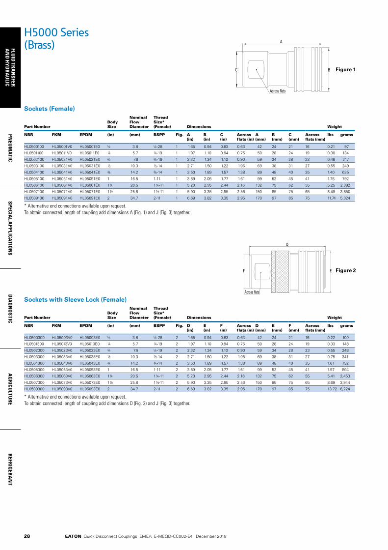
28
FLUID
TRAN
SFERA
ND
HYD
RAU
LICPN
EUM
ATICSPECIA
L APPLICATIO
NS
DIA
GN
OSTIC
AG
RICULTU
REREFRIG
ERAN
T
EATON Quick Disconnect Couplings EMEA E-MEQD-CC002-E4 December 2018
Sockets with Sleeve Lock (Female)
Part NumberBody Size
Nominal Flow Diameter
Thread Size* (Female) Dimensions Weight
NBR FKM EPDM (in) (mm) BSPP Fig. D (in)
E (in)
F (in)
Across flats (in)
D (mm)
E (mm)
F (mm)
Across flats (mm)
lbs grams
HL0500300 HL05003V0 HL05003E0 3.8 -28 2 1.65 0.94 0.83 0.63 42 24 21 16 0.22 100
HL0501300 HL05013V0 HL05013E0 ¼ 5.7 ¼-19 2 1.97 1.10 0.94 0.75 50 28 24 19 0.33 148
HL0502300 HL05023V0 HL05023E0 7.6 -19 2 2.32 1.34 1.10 0.90 59 34 28 23 0.55 248
HL0503300 HL05033V0 HL05033E0 ½ 10.3 ½-14 2 2.71 1.50 1.22 1.06 69 38 31 27 0.75 341
HL0504300 HL05043V0 HL05043E0 ¾ 14.2 ¾-14 2 3.50 1.89 1.57 1.38 89 48 40 35 1.61 732
HL0505300 HL05053V0 HL05053E0 1 16.5 1-11 2 3.89 2.05 1.77 1.61 99 52 45 41 1.97 894
HL0506300 HL05063V0 HL05063E0 1¼ 20.5 1¼-11 2 5.20 2.95 2.44 2.16 132 75 62 55 5.41 2,453
HL0507300 HL05073V0 HL05073E0 1½ 25.8 1½-11 2 5.90 3.35 2.95 2.56 150 85 75 65 8.69 3,944
HL0509300 HL05093V0 HL05093E0 2 34.7 2-11 2 6.69 3.82 3.35 2.95 170 97 85 75 13.72 6,224
* Alternative end connections available upon request.To obtain connected length of coupling add dimensions D (Fig. 2) and J (Fig. 3) together.
Sockets (Female)
Part NumberBody Size
Nominal Flow Diameter
Thread Size* (Female) Dimensions Weight
NBR FKM EPDM (in) (mm) BSPP Fig. A (in)
B (in)
C (in)
Across flats (in)
A (mm)
B (mm)
C (mm)
Across flats (mm)
lbs grams
HL0500100 HL05001V0 HL05001E0 3.8 -28 1 1.65 0.94 0.83 0.63 42 24 21 16 0.21 97
HL0501100 HL05011V0 HL05011E0 ¼ 5.7 ¼-19 1 1.97 1.10 0.94 0.75 50 28 24 19 0.30 134
HL0502100 HL05021V0 HL05021E0 7.6 -19 1 2.32 1.34 1.10 0.90 59 34 28 23 0.48 217
HL0503100 HL05031V0 HL05031E0 ½ 10.3 ½-14 1 2.71 1.50 1.22 1.06 69 38 31 27 0.55 249
HL0504100 HL05041V0 HL05041E0 ¾ 14.2 ¾-14 1 3.50 1.89 1.57 1.38 89 48 40 35 1.40 635
HL0505100 HL05051V0 HL05051E0 1 16.5 1-11 1 3.89 2.05 1.77 1.61 99 52 45 41 1.75 792
HL0506100 HL05061V0 HL05061E0 1¼ 20.5 1¼-11 1 5.20 2.95 2.44 2.16 132 75 62 55 5.25 2,382
HL0507100 HL05071V0 HL05071E0 1½ 25.8 1½-11 1 5.90 3.35 2.95 2.56 150 85 75 65 8.49 3,850
HL0509100 HL05091V0 HL05091E0 2 34.7 2-11 1 6.69 3.82 3.35 2.95 170 97 85 75 11.74 5,324
* Alternative end connections available upon request.To obtain connected length of coupling add dimensions A (Fig. 1) and J (Fig. 3) together.
H5000 Series(Brass) A
C B
Across flats
Across flats
D
EF
Figure 1
Figure 2

29
PNEU
MAT
ICSP
ECIA
L A
PPLI
CATI
ON
SD
IAG
NO
STIC
AG
RICU
LTU
RERE
FRIG
ERA
NT
FLU
ID T
RAN
SFER
AN
D H
YDRA
ULI
C
EATON Quick Disconnect Couplings EMEA E-MEQD-CC002-E4 December 2018
H5000 Series(Brass)
Plugs (Male)
Part NumberBody Size
Nominal Flow Diameter
Thread Size** (Female) Dimensions Weight
NBR* FKM EPDM (in) (mm) BSPP Fig. G (in)
H (in)
I (in)
J (in)
Hex (in)
G (mm)
H (mm)
I (mm)
J (mm)
Hex (mm)
lbs grams
HL0500200 HL05002V0 HL05002E0 3.8 -28 3 1.1 0.43 0.72 0.39 0.63 28 11 18.4 10 16 0.06 26
HL0501200 HL05012V0 HL05012E0 ¼ 5.7 ¼-19 3 1.38 0.56 0.86 0.55 0.75 35 14.2 21.8 14 19 0.09 41
HL0502200 HL05022V0 HL05022E0 7.6 -19 3 1.65 0.75 1.04 0.70 0.90 42 19 26.4 18 23 0.17 77
HL0503200 HL05032V0 HL05032E0 ½ 10.3 ½-14 3 1.97 0.81 1.22 0.94 1.06 50 20.6 31 24 27 0.22 101
HL0504200 HL05042V0 HL05042E0 ¾ 14.2 ¾-14 3 2.48 1.10 1.58 1.10 1.38 63 27.9 40.2 28 35 0.53 239
HL0505200 HL05052V0 HL05052E0 1 16.5 1-11 3 2.79 1.27 1.87 1.22 1.61 71 32.4 47.5 31 41 0.70 316
- HL05062V0 HL05062E0 1¼ 20.5 1¼-11 3 3.82 1.85 2.49 1.89 2.16 97 46.9 63.2 48 55 2.18 990
- HL05072V0 HL05072E0 1½ 25.8 1½-11 3 4.29 2.20 2.94 2.04 2.56 109 56 74.7 52 65 3.64 1650
- HL05092V0 HL05092E0 2 34.7 2-11 3 4.76 2.56 3.30 1.97 2.95 121 65 84 50 75 4.46 2024
* Body sizes 1¼, 1½ and 2 are supplied with FKM seals as a standard.** Alternative end connections available upon request. To obtain connected length of coupling add dimensions A (Fig. 1) and J (Fig. 3) together for standard version; add dimensions D (Fig. 2) and J (Fig. 3) together for sleeve lock version
JG
H I
Hex
Dust Plugs and Dust CapsBody Size Socket Dust Plug Part Number Plug Dust Cap Part Number
(in) Anodized Aluminum Anodized Aluminum
HD0510100 HD0510200
¼ HD0511100 HD0511200
HD0512100 HD0512200
½ HD0513100 HD0513200
¾ HD0514100 HD0514200
1 HD0515100 HD0515200
1¼ HD0516100 HD0516200
1½ HD0517100 HD0517200
2 HD0519100 HD0519200
Socket Dust Plug
Plug Dust Cap
Figure 3
Seal Kit for Servicing Sockets (Female)
Body Size Seal & Back-up Ring Kit*
(in) NBR seals & PTFE back-up rings
Qty FKM seals & PTFE back-up rings
Qty EPDM seals & PTFE back-up rings
Qty
1/8 HG 05001 00 50 O-rings + 50 Backup rings HG 05001 V0 15 O-rings + 15 Backup rings HG 05001 E0 15 O-rings + 15 Backup rings
1/4 HG 05011 00 50 O-rings + 50 Backup rings HG 05011 V0 15 O-rings + 15 Backup rings HG 05011 E0 15 O-rings + 15 Backup rings
3/8 HG 05021 00 50 O-rings + 50 Backup rings HG 05021 V0 15 O-rings + 15 Backup rings HG 05021 E0 15 O-rings + 15 Backup rings
1/2 HG 05031 00 50 O-rings + 50 Backup rings HG 05031 V0 15 O-rings + 15 Backup rings HG 05031 E0 15 O-rings + 15 Backup rings
3/4 HG 05041 00 50 O-rings + 50 Backup rings HG 05041 V0 15 O-rings + 15 Backup rings HG 05041 E0 15 O-rings + 15 Backup rings
1 HG 05051 00 50 O-rings + 50 Backup rings HG 05051 V0 10 O-rings + 10 Backup rings HG 05051 E0 10 O-rings + 10 Backup rings
1 1/4 HG 05061 00 15 O-rings + 15 Backup rings HG 05061 V0 5 O-rings + 5 Backup rings - -
1 1/2 HG 05071 00 15 O-rings + 15 Backup rings - - - -
2 HG 05091 00 15 O-rings + 15 Backup rings - - - -
*The valve seal is not included in our repair kits

30
FLUID
TRAN
SFERA
ND
HYD
RAU
LICPN
EUM
ATICSPECIA
L APPLICATIO
NS
DIA
GN
OSTIC
AG
RICULTU
REREFRIG
ERAN
T
EATON Quick Disconnect Couplings EMEA E-MEQD-CC002-E4 December 2018
0.264 2.64 26.4 0.1
1
0.5
0.3
0.2
54
3
1 10 100 1000
Flow Rate (gpm)
Pre
ssu
re d
rop
(P
SI)
Pre
ssu
re d
rop
(b
ar)
Flow Rate (l/min)
72.5
1.45
14.5
43.5
4.35
7.25
58
29
2.9
2
264
1/8
1/4
3/8
1/2
3/4
1" 1" 1
/4
1" 1
/2
2"
H5000 Series(Stainless Steel)
Physical Characteristics
Max. Operating Pressure*
Body Size
Nominal Flow Diameter
Non hazardous liquids & gases Group 2
Hazardous liquids & gases Group 1 Rated Flow** Fluid Loss
(in) (mm) (bar) (psi) (bar) (psi) (lpm) (gpm) ml-cc.
3.8 300 4,350 300 4,350 6.1 1.61 0.4
¼ 5.7 230 3,335 230 3,335 11.6 3.06 1
7.6 175 2,535 175 2,535 16.7 4.41 2
½ 10.3 150 2,175 150 2,175 25.5 6.74 2.5
¾ 14.2 125 1,810 125 1,810 55 14.53 5.5
1 16.5 100 1,450 100 1,450 87 22.98 9
1¼ 20.5 100 1,450 100 1,450 140 36.98 23
1½ 25.8 75 1,085 28 550 208 54.95 36
2 34.7 40 580 38 405 357 94.30 70
* For pulsating pressures when disconnected apply a multiplier of 0.5** Indicated values refer to a 1 bar/14.5 psi pressure drop.
• Proprietary profile• Pull-to-connect with double shut-off
valving• Ball-locking
• Optional safety sleeve lock prevents accidental disconnections
• Optional dust caps and plugs (made of anodized aluminum)
• Pressure performance
• Standard body material: AISI 316L Stainless steel
• Standard seal material: FKM, EPDM
Product Features
Seal Elastomer Data* Seal Elastomer Max. Operation Temperature Range
FKM -20°C +200°C/-4°F +392°F
EPDM (Ethylene-Propylene)** -40°C +150°C/-40°F +302°F
* For reference only, based on Eaton recommended temperatures.** In accordance with NF L 17-241 or NAS 1613 rev. 5Contact Eaton technical support for further information on fluid compatibility.
Couplings with nominal diameters up to and including 25 mm are designed and manufactured under Article 4.3 of the European Pressure Equipment Directive PED 2014/68/EU. Couplings with nominal diameters greater than 25 mm are designed and manufactured in accordance with the stipulations of Module A of the European Pressure Equipment Directive PED 2014/68/EU. They should not be used to convey unstable gases.Group 1 = Hazardous media / Group 2 = Other media
European Pressure Equipment Directive
Applications & Markets• Automobile• Agriculture• Construction• Oil and Gas• Railway• Aeronautics• Food Processing • Iron and Steel Industry• Electronics• Laboratories• General Hydraulic
ApplicationsTest Fluid: Oil viscosity 30 cSt at 40°C/104°F
Flow Data
Eaton’s H5000 Series stainless steel quick disconnect coupling is a pull to connect double shut-off coupling. It is a general purpose industrial coupling with the original Eaton’s Gromelle™ profile. It is mainly used in fluid transfer applications and provides excellent corrosion resistance.

31
PNEU
MAT
ICSP
ECIA
L A
PPLI
CATI
ON
SD
IAG
NO
STIC
AG
RICU
LTU
RERE
FRIG
ERA
NT
FLU
ID T
RAN
SFER
AN
D H
YDRA
ULI
C
EATON Quick Disconnect Couplings EMEA E-MEQD-CC002-E4 December 2018
H5000 Series(Stainless Steel)
Sockets (Female)
Part Number Body Size
Nominal Flow Diameter Thread Size* (Female) Dimensions Weight
FKM EPDM (in) (mm) NPT BSPP Fig. A (in)
B (in)
C (in)
Across flats (in)
A (mm)
B (mm)
C (mm)
Across flats (mm)
lbs grams
HZ05001V0 HZ05001E0 3.8 - -28 1 1.65 0.94 0.83 0.63 42 24 21 16 0.19 88
HZ05201V0 HZ05201E0 3.8 -27 - 1 1.65 0.94 0.83 0.63 42 24 21 16 0.19 88
HZ05011V0 HZ05011E0 ¼ 5.7 - ¼-19 1 1.97 1.10 0.94 0.75 50 28 24 19 0.27 122
HZ05211V0 HZ05211E0 ¼ 5.7 ¼-18 - 1 1.97 1.10 0.94 0.75 50 28 24 19 0.27 122
HZ05021V0 HZ05021E0 7.6 - -19 1 2.32 1.34 1.10 0.90 59 34 28 23 0.43 197
HZ05221V0 HZ05221E0 7.6 -18 - 1 2.32 1.34 1.10 0.90 59 34 28 23 0.43 197
HZ05031V0 HZ05031E0 ½ 10.3 - ½-14 1 2.71 1.50 1.22 1.06 69 38 31 27 0.50 226
HZ05231V0 HZ05231E0 ½ 10.3 ½-14 - 1 2.71 1.50 1.22 1.06 69 38 31 27 0.50 226
HZ05041V0 HZ05041E0 ¾ 14.2 - ¾-14 1 3.50 1.89 1.57 1.38 89 48 40 35 1.27 577
HZ05241V0 HZ05241E0 ¾ 14.2 ¾-14 - 1 3.50 1.89 1.57 1.38 89 48 40 35 1.27 577
HZ05051V0 HZ05051E0 1 16.5 - 1-11 1 3.89 2.05 1.77 1.61 99 52 45 41 1.59 720
HZ05251V0 HZ05251E0 1 16.5 1-11½ - 1 3.89 2.05 1.77 1.61 99 52 45 41 1.59 720
HZ05061V0 HZ05061E0 1¼ 20.5 - 1¼-11 1 5.20 2.95 2.44 2.16 132 75 62 55 4.77 2,165
HZ05071V0 HZ05071E0 1½ 25.8 - 1½-11 1 5.90 3.35 2.95 2.56 150 85 75 65 7.72 3,500
HZ05091V0 HZ05091E0 2 34.7 - 2-11 1 6.69 3.82 3.35 2.95 170 97 85 75 10.67 4,840
* Alternative end connections available upon request.To obtain connected length of coupling add dimensions A (Fig. 1) and J (Fig. 3) together.
Sockets with Sleeve Lock (Female)
Part Number Body Size
Nominal Flow Diameter
Thread Size* (Female) Dimensions Weight
FKM EPDM (in) (mm) BSPP Fig. D (in)
E (in)
F (in)
Across flats (in)
D (mm)
E (mm)
F (mm)
Across flats (mm)
lbs grams
HZ05003V0 HZ05003E0 3.8 -28 2 1.65 0.94 0.83 0.63 42 24 21 16 0.19 91
HZ05013V0 HZ05013E0 ¼ 5.7 ¼-19 2 1.97 1.10 0.94 0.75 50 28 24 19 0.27 134
HZ05023V0 HZ05023E0 7.6 -19 2 2.32 1.34 1.10 0.90 59 34 28 23 0.43 225
HZ05033V0 HZ05033E0 ½ 10.3 ½-14 2 2.71 1.50 1.22 1.06 69 38 31 27 0.50 310
HZ05043V0 HZ05043E0 ¾ 14.2 ¾-14 2 3.50 1.89 1.57 1.38 89 48 40 35 1.27 665
HZ05053V0 HZ05053E0 1 16.5 1-11 2 3.89 2.05 1.77 1.61 99 52 45 41 1.59 813
HZ05063V0 HZ05063E0 1¼ 20.5 1¼-11 2 5.20 2.95 2.44 2.16 132 75 62 55 4.77 2,230
HZ05073V0 HZ05073E0 1½ 25.8 1½-11 2 5.90 3.35 2.95 2.56 150 85 75 65 7.72 3,585
HZ05093V0 HZ05093E0 2 34.7 2-11 2 6.69 3.82 3.35 2.95 170 97 85 75 10.67 5,658
* Alternative end connections available upon request.To obtain connected length of coupling add dimensions D (Fig. 2) and J (Fig. 3) together.
A
C B
Across flats
Across flats
D
EF
Figure 1
Figure 2

32
FLUID
TRAN
SFERA
ND
HYD
RAU
LICPN
EUM
ATICSPECIA
L APPLICATIO
NS
DIA
GN
OSTIC
AG
RICULTU
REREFRIG
ERAN
T
EATON Quick Disconnect Couplings EMEA E-MEQD-CC002-E4 December 2018
H5000 Series(Stainless Steel)
Dust Plugs and Dust CapsBody Size Socket Dust Plug Part Number Plug Dust Cap Part Number
(in) Anodized Aluminum Anodized Aluminum
HD0510100 HD0510200
¼ HD0511100 HD0511200
HD0512100 HD0512200
½ HD0513100 HD0513200
¾ HD0514100 HD0514200
1 HD0515100 HD0515200
1¼ HD0516100 HD0516200
1½ HD0517100 HD0517200
2 HD0519100 HD0519200
Plugs (Male)
Part Number Body Size
Nominal Flow Diameter Thread Size* (Female) Dimensions Weight
FKM EPDM (in) (mm) NPT BSPP Fig. G (in)
H (in)
I (in)
J (in)
Hex (in)
G (mm)
H (mm)
I (mm)
J (mm)
Hex (mm)
lbs grams
HZ05002V0 HZ05002E0 3.8 - -28 3 1.10 0.43 0.72 0.39 0.63 28 11 18.4 10 16 0.05 23
HZ05202V0 HZ05202E0 3.8 -27 - 3 1.10 0.43 0.72 0.39 0.63 28 11 18.4 10 16 0.05 23
HZ05012V0 HZ05012E0 ¼ 5.7 - ¼-19 3 1.38 0.56 0.86 0.55 0.75 35 14.2 21.8 14 19 0.08 37
HZ05212V0 HZ05212E0 ¼ 5.7 ¼-18 - 3 1.38 0.56 0.86 0.55 0.75 35 14.2 21.8 14 19 0.08 37
HZ05022V0 HZ05022E0 7.6 - -19 3 1.65 0.75 1.04 0.70 0.90 42 19 26.4 18 23 0.15 70
HZ05222V0 HZ05222E0 7.6 -18 - 3 1.65 0.75 1.04 0.70 0.90 42 19 26.4 18 23 0.15 70
HZ05032V0 HZ05032E0 ½ 10.3 - ½-14 3 1.97 0.81 1.22 0.94 1.06 50 20.6 31 24 27 0.20 92
HZ05232V0 HZ05232E0 ½ 10.3 ½-14 - 3 1.97 0.81 1.22 0.94 1.06 50 20.6 31 24 27 0.20 92
HZ05042V0 HZ05042E0 ¾ 14.2 - ¾-14 3 2.48 1.10 1.58 1.10 1.38 63 27.9 40.2 28 35 0.48 217
HZ05242V0 HZ05242E0 ¾ 14.2 ¾-14 - 3 2.48 1.10 1.58 1.10 1.38 63 27.9 40.2 28 35 0.48 217
HZ05052V0 HZ05052E0 1 16.5 - 1-11 3 2.79 1.27 1.87 1.22 1.61 71 32.4 47.5 31 41 0.63 287
HZ05252V0 HZ05252E0 1 16.5 1-11½ - 3 2.79 1.27 1.87 1.22 1.61 71 32.4 47.5 31 41 0.63 287
HZ05062V0 HZ05062E0 1¼ 20.5 - 1¼-11 3 3.82 1.85 2.49 1.89 2.16 97 46.9 63.2 48 55 1.98 900
HZ05072V0 HZ05072E0 1½ 25.8 - 1½-11 3 4.29 2.20 2.94 2.04 2.56 109 56 74.7 52 65 3.30 1500
HZ05092V0 HZ05092E0 2 34.7 - 2-11 3 4.76 2.56 3.30 1.97 2.95 121 65 84 50 75 4.06 1840
* Alternative end connections available upon request.To obtain connected length of coupling add dimensions A (Fig. 1) and J (Fig. 3) together for standard version; add Dimensions D (Fig. 2) and J (Fig. 3) together for sleeve lock version
Socket Dust Plug
Plug Dust Cap
JG
H I
Hex
Figure 3
Seal Kit for Servicing Sockets (Female)
Body Size Seal & Back-up Ring Kit*
(in) NBR seals & PTFE back-up rings
Qty FKM seals & PTFE back-up rings
Qty EPDM seals & PTFE back-up rings
Qty
1/8 HG 05001 00 50 O-rings + 50 Backup rings HG 05001 V0 15 O-rings + 15 Backup rings HG 05001 E0 15 O-rings + 15 Backup rings
1/4 HG 05011 00 50 O-rings + 50 Backup rings HG 05011 V0 15 O-rings + 15 Backup rings HG 05011 E0 15 O-rings + 15 Backup rings
3/8 HG 05021 00 50 O-rings + 50 Backup rings HG 05021 V0 15 O-rings + 15 Backup rings HG 05021 E0 15 O-rings + 15 Backup rings
1/2 HG 05031 00 50 O-rings + 50 Backup rings HG 05031 V0 15 O-rings + 15 Backup rings HG 05031 E0 15 O-rings + 15 Backup rings
3/4 HG 05041 00 50 O-rings + 50 Backup rings HG 05041 V0 15 O-rings + 15 Backup rings HG 05041 E0 15 O-rings + 15 Backup rings
1 HG 05051 00 50 O-rings + 50 Backup rings HG 05051 V0 10 O-rings + 10 Backup rings HG 05051 E0 10 O-rings + 10 Backup rings
1 1/4 HG 05061 00 15 O-rings + 15 Backup rings HG 05061 V0 5 O-rings + 5 Backup rings - -
1 1/2 HG 05071 00 15 O-rings + 15 Backup rings - - - -
2 HG 05091 00 15 O-rings + 15 Backup rings - - - -
*The valve seal is not included in our repair kits
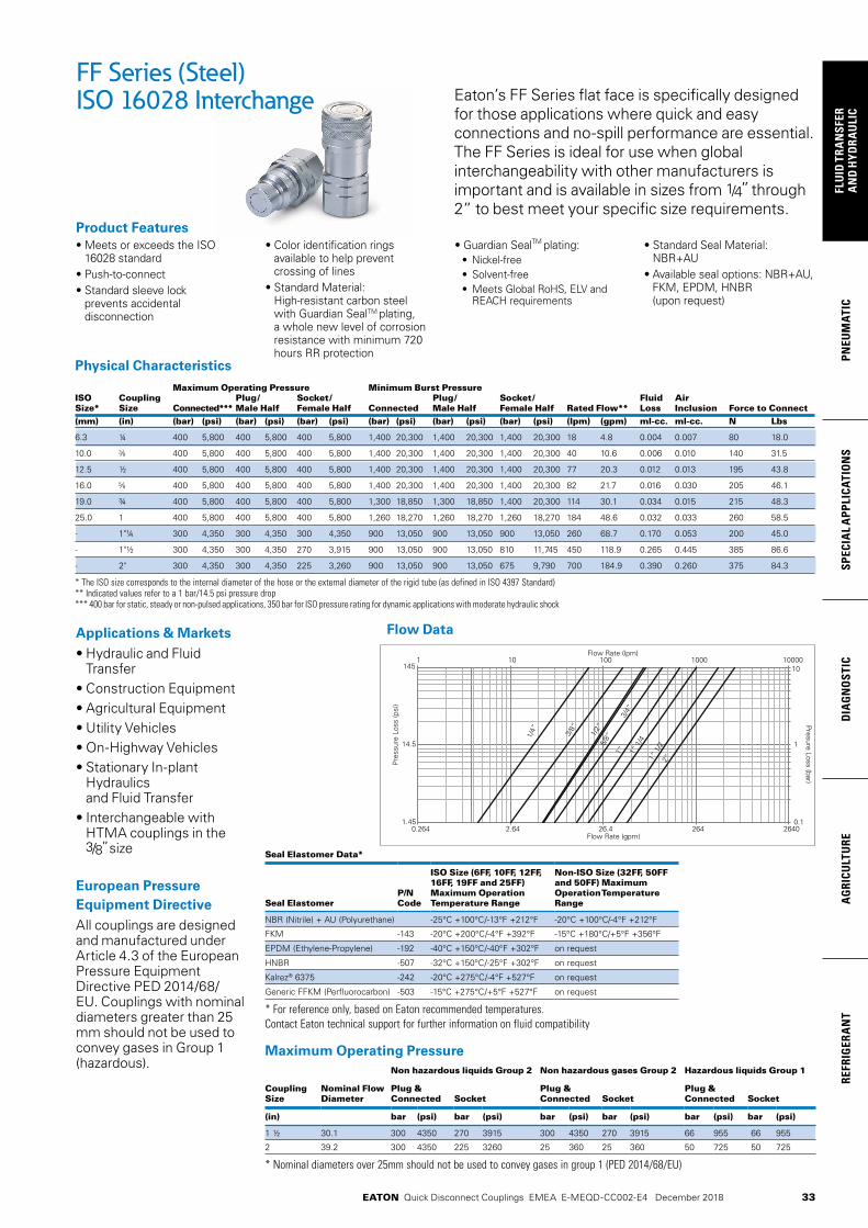
33
PNEU
MAT
ICSP
ECIA
L A
PPLI
CATI
ON
SD
IAG
NO
STIC
AG
RICU
LTU
RERE
FRIG
ERA
NT
FLU
ID T
RAN
SFER
AN
D H
YDRA
ULI
C
EATON Quick Disconnect Couplings EMEA E-MEQD-CC002-E4 December 2018
Eaton’s FF Series flat face is specifically designed for those applications where quick and easy connections and no-spill performance are essential. The FF Series is ideal for use when global interchangeability with other manufacturers is important and is available in sizes from 1/4” through 2” to best meet your specific size requirements.
Physical Characteristics Maximum Operating Pressure Minimum Burst Pressure ISO Coupling Plug/ Socket/ Plug/ Socket/ Fluid Air Size* Size Connected*** Male Half Female Half Connected Male Half Female Half Rated Flow** Loss Inclusion Force to Connect(mm) (in) (bar) (psi) (bar) (psi) (bar) (psi) (bar) (psi) (bar) (psi) (bar) (psi) (lpm) (gpm) ml-cc. ml-cc. N Lbs
6.3 ¼ 400 5,800 400 5,800 400 5,800 1,400 20,300 1,400 20,300 1,400 20,300 18 4.8 0.004 0.007 80 18.0
10.0 400 5,800 400 5,800 400 5,800 1,400 20,300 1,400 20,300 1,400 20,300 40 10.6 0.006 0.010 140 31.5
12.5 ½ 400 5,800 400 5,800 400 5,800 1,400 20,300 1,400 20,300 1,400 20,300 77 20.3 0.012 0.013 195 43.8
16.0 400 5,800 400 5,800 400 5,800 1,400 20,300 1,400 20,300 1,400 20,300 82 21.7 0.016 0.030 205 46.1
19.0 ¾ 400 5,800 400 5,800 400 5,800 1,300 18,850 1,300 18,850 1,400 20,300 114 30.1 0.034 0.015 215 48.3
25.0 1 400 5,800 400 5,800 400 5,800 1,260 18,270 1,260 18,270 1,260 18,270 184 48.6 0.032 0.033 260 58.5
- 1"¼ 300 4,350 300 4,350 300 4,350 900 13,050 900 13,050 900 13,050 260 68.7 0.170 0.053 200 45.0
- 1"½ 300 4,350 300 4,350 270 3,915 900 13,050 900 13,050 810 11,745 450 118.9 0.265 0.445 385 86.6
- 2" 300 4,350 300 4,350 225 3,260 900 13,050 900 13,050 675 9,790 700 184.9 0.390 0.260 375 84.3
* The ISO size corresponds to the internal diameter of the hose or the external diameter of the rigid tube (as defined in ISO 4397 Standard) ** Indicated values refer to a 1 bar/14.5 psi pressure drop *** 400 bar for static, steady or non-pulsed applications, 350 bar for ISO pressure rating for dynamic applications with moderate hydraulic shock
FF Series (Steel)ISO 16028 Interchange
Product Features
Applications & Markets• Hydraulic and Fluid
Transfer• Construction Equipment• Agricultural Equipment• Utility Vehicles• On-Highway Vehicles• Stationary In-plant
Hydraulics and Fluid Transfer
• Interchangeable with HTMA couplings in the 3/8” size
European Pressure Equipment DirectiveAll couplings are designed and manufactured under Article 4.3 of the European Pressure Equipment Directive PED 2014/68/EU. Couplings with nominal diameters greater than 25 mm should not be used to convey gases in Group 1 (hazardous).
Seal Elastomer Data*
Seal ElastomerP/N Code
ISO Size (6FF, 10FF, 12FF, 16FF, 19FF and 25FF) Maximum Operation Temperature Range
Non-ISO Size (32FF, 50FF and 50FF) Maximum Operation Temperature Range
NBR (Nitrile) + AU (Polyurethane) -25°C +100°C/-13°F +212°F -20°C +100°C/-4°F +212°F
FKM -143 -20°C +200°C/-4°F +392°F -15°C +180°C/+5°F +356°F
EPDM (Ethylene-Propylene) -192 -40°C +150°C/-40°F +302°F on request
HNBR -507 -32°C +150°C/-25°F +302°F on request
Kalrez® 6375 -242 -20°C +275°C/-4°F +527°F on request
Generic FFKM (Perfluorocarbon) -503 -15°C +275°C/+5°F +527°F on request
* For reference only, based on Eaton recommended temperatures. Contact Eaton technical support for further information on fluid compatibility
Flow Data
Maximum Operating PressureNon hazardous liquids Group 2 Non hazardous gases Group 2 Hazardous liquids Group 1
Coupling Size
Nominal Flow Diameter
Plug & Connected Socket
Plug & Connected Socket
Plug & Connected Socket
(in) bar (psi) bar (psi) bar (psi) bar (psi) bar (psi) bar (psi)
1 ½ 30.1 300 4350 270 3915 300 4350 270 3915 66 955 66 955
2 39.2 300 4350 225 3260 25 360 25 360 50 725 50 725
* Nominal diameters over 25mm should not be used to convey gases in group 1 (PED 2014/68/EU)
1 10 100 1000 10000
0.1
1
10
1.45
14.5
1/4” 3/8”
1/2”
5/8”
3/4”
1” 1” 1
/41”
1/2
2”145
0.264 2.64 26.4 264 2640
Flow Rate (lpm)
Presure Loss (bar)
Flow Rate (gpm)
Pre
ssur
e Lo
ss (p
si)
• Meets or exceeds the ISO 16028 standard
• Push-to-connect• Standard sleeve lock
prevents accidental disconnection
• Color identification rings available to help prevent crossing of lines
• Standard Material: High-resistant carbon steel with Guardian SealTM plating, a whole new level of corrosion resistance with minimum 720 hours RR protection
• Guardian SealTM plating:• Nickel-free• Solvent-free• Meets Global RoHS, ELV and
REACH requirements
• Standard Seal Material: NBR+AU
• Available seal options: NBR+AU, FKM, EPDM, HNBR (upon request)

34
FLUID
TRAN
SFERA
ND
HYD
RAU
LICPN
EUM
ATICSPECIA
L APPLICATIO
NS
DIA
GN
OSTIC
AG
RICULTU
REREFRIG
ERAN
T
EATON Quick Disconnect Couplings EMEA E-MEQD-CC002-E4 December 2018
Sockets (Female) Body ISO Nominal Flow Part Number Size Size Diameter Thread Size* (Female) Dimensions Weight
NBR+AU (in) (mm) (mm) NPT BSPP ISO 6149-1 SAE J 1926-1 Eaton S013A Fig. A (in) B (in) C (in) Hex (in) A (mm) B (mm) C (mm) Hex (mm) lbs grams
6FFS25 ¼ 6.3 6 ¼ 18f 1 2.13 1.06 0.94 0.87 54 27 24 22 - -
6FFS25BS ¼ 6.3 6 ¼-19 1 2.13 1.06 0.94 0.87 54 27 24 22 - -
6FFS25FG ¼ 6.3 6 G ¼ 1 2.13 1.06 0.94 0.87 54 27 24 22 0.32 143
6FFS56UN ¼ 6.3 6 18f UNF 1 2.17 1.06 0.94 0.87 55 27 24 22 - -
10FFS16FMET 10 8.6 M16x1.5 1 2.67 1.26 1.16 1.06 67.8 32 29.5 27 - -
10FFS37 10 8.6 18f 1 2.67 1.26 1.16 1.06 67.8 32 29.5 27 - -
10FFS37BS 10 8.6 -19 1 2.67 1.26 1.16 1.06 67.8 32 29.5 27 - -
10FFS37FG 10 8.6 G 1 2.67 1.26 1.16 1.06 67.8 32 29.5 27 0.56 255
10FFS50 10 8.6 ½ 14f 1 2.79 1.26 1.16 1.06 70.8 32 29.5 27 - -
10FFS50BS 10 8.6 ½-14 1 2.79 1.26 1.16 1.06 70.8 32 29.5 27 - -
10FFS50FG 10 8.6 G ½ 1 2.79 1.26 1.16 1.06 70.8 32 29.5 27 0.55 251
10FFS56UN 10 8.6 18f UNF 1 2.79 1.26 1.16 1.06 70.8 32 29.5 27 - -
10FFS75UN 10 8.6 ¾ 16f UNF 1 2.79 1.26 1.16 1.06 70.8 32 29.5 27 - -
10FFS87UN 10 8.6 14f UNF 1 2.91 1.26 1.30 1.18 73.8 32 33 30 - -
12FFS106UN ½ 12.5 11 1 12f UN 1 3.50 1.50 1.56 1.42 89 38.2 39.5 36 - -
12FFS50 ½ 12.5 11 ½ 14f 1 3.27 1.50 1.56 1.42 83 38.2 39.5 36 - -
12FFS50BS ½ 12.5 11 ½-14 1 3.27 1.50 1.56 1.42 83 38.2 39.5 36 - -
12FFS50FG ½ 12.5 11 G ½ 1 3.27 1.50 1.56 1.42 83 38.2 39.5 36 1.1 498
12FFS75 ½ 12.5 11 ¾ 14f 1 3.39 1.50 1.56 1.42 86 38.2 39.5 36 - -
12FFS75BS ½ 12.5 11 ¾-14 1 3.39 1.50 1.56 1.42 86 38.2 39.5 36 - -
12FFS75FG ½ 12.5 11 G ¾ 1 3.39 1.50 1.56 1.42 86 38.2 39.5 36 1.08 488
12FFS75UN ½ 12.5 11 ¾ 16f UNF 1 3.27 1.50 1.56 1.42 83 38.2 39.5 36 - -
12FFS87UN ½ 12.5 11 14f UNF 1 3.39 1.50 1.56 1.42 86 38.2 39.5 36 - -
16FFS106UN 16 13 1 12f UN 1 3.50 1.66 1.56 1.42 89 42.2 39.5 36 - -
16FFS50 16 13 ½ 14f 1 3.27 1.66 1.56 1.42 83 42.2 39.5 36 - -
16FFS50BS 16 13 ½-14 1 3.27 1.66 1.56 1.42 83 42.2 39.5 36 -
16FFS75 16 13 ¾ 14f 1 3.39 1.66 1.56 1.42 86 42.2 39.5 36 - -
16FFS75BS 16 13 ¾-14 1 3.39 1.66 1.56 1.42 86 42.2 39.5 36 - -
16FFS75FG 16 13 G ¾ 1 3.39 1.66 1.56 1.42 86 42.2 39.5 36 1.20 548
16FFS75UN 16 13 ¾ 16f UNF 1 3.27 1.66 1.56 1.42 83 42.2 39.5 36 - -
16FFS87UN 16 13 14f UNF 1 3.39 1.66 1.56 1.42 86 42.2 39.5 36 - -
19FFS100 ¾ 19 15 1 11,5f 1 3.80 1.82 1.81 1.65 96.6 46.2 46 42 - -
19FFS100BS ¾ 19 15 1-11 1 3.80 1.82 1.81 1.65 96.6 46.2 46 42 - -
19FFS100FG ¾ 19 15 G 1 1 3.80 1.82 1.81 1.65 96.6 46.2 46 42 1.62 737
19FFS106UN ¾ 19 15 1 12f UN 1 3.80 1.82 1.81 1.65 96.6 46.2 46 42 - -
19FFS131UN ¾ 19 15 1 12f UN 1 3.80 1.82 1.81 1.65 96.6 46.2 46 42 - -
19FFS75 ¾ 19 15 ¾ 14f 1 3.80 1.82 1.81 1.65 96.6 46.2 46 42 - -
19FFS75BS ¾ 19 15 ¾-14 1 3.80 1.82 1.81 1.65 96.6 46.2 46 42 - -
25FFS100 1 25 18 1 11,5f 1 4.07 2.17 2.36 2.17 103.5 55.2 60 55 - -
25FFS100BS 1 25 18 1-11 1 4.07 2.17 2.36 2.17 103.5 55.2 60 55 - -
25FFS125 1 25 18 1 ¼ 11,5f 1 4.07 2.17 2.36 2.17 103.5 55.2 60 55 - -
25FFS125BS 1 25 18 1 ¼-11 1 4.07 2.17 2.36 2.17 103.5 55.2 60 55 - -
25FFS125FG 1 25 18 G 1¼ 1 4.07 2.17 2.36 2.17 103.5 55.2 60 55 2.74 1246
25FFS131UN 1 25 18 1 12f UN 1 4.07 2.17 2.36 2.17 103.5 55.2 60 55 2.77 126
25FFS162UN 1 25 18 1 12f UN 1 4.07 2.17 2.36 2.17 103.5 55.2 60 55 - -
32FFS125 1 ¼ - 22.1 1 ¼-11,5 1 4.93 2.55 2.36 2.17 125.2 64.8 60 55 4.22 1915
32FFS125BS 1 ¼ - 22.1 1 ¼-11 1 4.93 2.55 2.36 2.17 125.2 64.8 60 55 4.18 1897
32FFS162UN 1 ¼ - 22.1 1 12 UN 1 4.93 2.55 2.36 2.17 125.2 64.8 60 55 4.16 1894
40FFS150 1 ½ - 30.1 1 ½-11,5 1 5.01 3.13 2.76 2.56 127.4 79.5 70 65 6.16 2796
40FFS150BS 1 ½ - 30.1 1 ½-11 1 5.01 3.13 2.76 2.56 127.4 79.5 70 65 6.13 2781
40FFS150FG 1 ½ - 30.1 1 ½ 1 5.01 3.13 2.76 2.56 127.4 79.5 70 65 6.12 2775
40FFS187UN 1 ½ - 30.1 1 12 UN 1 5.01 3.13 2.76 2.56 127.4 79.5 70 65 6.10 2767
50FFS200 2 - 39.2 2-11,5 1 6.17 3.84 3.46 3.15 156.8 97.5 87.8 80 10.87 4931
50FFS200BS 2 - 39.2 2-11 1 6.17 3.84 3.46 3.15 156.8 97.5 87.8 80 10.82 4908
50FFS250UN 2 - 39.2 2 ½ 12 UN 1 6.17 3.84 3.46 3.15 156.8 97.5 87.8 80 10.64 4825
*Alternative end connections available upon request. To obtain connected length of coupling, add dimensions A (Fig. 1 or Fig. 2) and G (Fig. 3 or 4) together.
FF Series (Steel)ISO 16028 Interchange
ISO 6149-1 SAE J 1926-1 EATON S013A15° + metric thread 15° + UN/UNF thread 15° + BSPP thread
Figure 1

35
PNEU
MAT
ICSP
ECIA
L A
PPLI
CATI
ON
SD
IAG
NO
STIC
AG
RICU
LTU
RERE
FRIG
ERA
NT
FLU
ID T
RAN
SFER
AN
D H
YDRA
ULI
C
EATON Quick Disconnect Couplings EMEA E-MEQD-CC002-E4 December 2018
Sockets (Female) Body ISO Nominal Flow Part Number Size Size Diameter Thread Size*(Male) Dimensions Weight
NBR+AU (in) (mm) (mm) ISO 8434-1 SAE J 1926-2 Fig. A (in) B (in) C (in) H (in.) Hex (in) A (mm) B (mm) C (mm) H (mm) Hex (mm) lbs grams
6FFS10LBH ¼ 6.3 6 10L - M16x1,5 2 1.65 1.06 0.94 1.38 0.87 42 27 24 35 22 – – + bulkhead
10FFS8L 10 6 8L - M14x1,5 2 2.33 1.26 1.16 0.39 1.06 59.3 32 29.5 10 27 0.52 236
10FFS10L 10 8 10L - M16x1,5 2 2.33 1.26 1.16 0.43 1.06 59.3 32 29.5 11 27 0.52 234
10FFS12L 10 10 12L - M18x1,5 2 2.28 1.26 1.16 0.43 1.06 57.8 32 29.5 11 27 0.52 235
10FFS15L 10 8,6 15L - M22x1,5 2 2.24 1.26 1.16 0.47 1.06 56.8 32 29.5 12 27 0.52 238
10FFS15LBH 10 8,6 15L - M22x1,5 2 3.24 1.26 1.16 1.50 1.06 82.3 32 29.5 38 27 0.62 282
10FFS16S 10 8,6 16S - M24x1,5 2 2.26 1.26 1.16 0.55 1.06 57.3 32 29.5 14 27 0.46 211 + bulkhead
10FFS56ORM 10 8,6 18f UNF 2 2.61 1.26 1.06 0.47 0.94 66.4 32 27 12 23.8 – –
10FFS75ORM 10 8,6 ¾ 16f UNF 2 2.61 1.26 1.06 0.55 0.94 66.4 32 27 14 23.8 – –
12FFS15LBH ½ 12 11 15L - M22x1,5 2 3.66 1.50 1.56 1.50 1.42 93 38.2 39.5 38 36 1.05 478 + bulkhead
12FFS16S ½ 12 11 16S - M24x1,5 2 2.75 1.50 1.56 0.55 1.42 70 38.2 39.5 14 36 1.01 460
12FFS18LBH ½ 12 11 18L - M26x1,5 2 3.74 1.50 1.56 1.57 1.42 95 38.2 39.5 40. 36 1.17 534 + bulkhead
16FFS15LBH 16 12 15L - M22x1,5 2 2.68 1.66 1.56 1.50 1.42 68 42.2 39.5 38 36 – – + bulkhead
16FFS16S 16 12 16S - M24x1,5 2 2.75 1.66 1.56 0.55 1.42 70 42.2 39.5 14 36 1.11 505
16FFS18LBH 16 13 18L - M26x1,5 2 2.68 1.66 1.56 1.57 1.42 68 42.2 39.5 40 36 – – + bulkhead
* Alternative end connections available upon request. To obtain connected length of coupling, add dimensions A (Fig. 1 or Fig. 2) and G (Fig. 3 or 4) together. Note that ISO 8434-1 will restrict usage of coupling to 250 bar for end connection 8L, 10L, 12L and 15L, and to 160 bar for end connection 18L.
FF Series (Steel)ISO 16028 Interchange
ISO 8434-1 ISO 8434-1 + Bulkhead SAE J 1926-2Metric thread Metric thread UN/UNF thread
G
B
E
HEX
C
HA
HEX
F
DH
G
B
E
HEX
C
HA
HEX
F
DH
G
B
E
HEX
C
HA
HEX
F
DHG
B
E
HEX
C
HA
HEX
F
DH
Figure 2
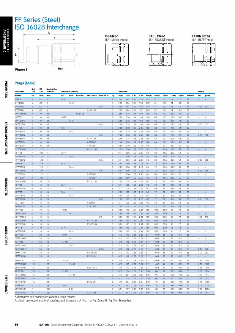
36
FLUID
TRAN
SFERA
ND
HYD
RAU
LICPN
EUM
ATICSPECIA
L APPLICATIO
NS
DIA
GN
OSTIC
AG
RICULTU
REREFRIG
ERAN
T
EATON Quick Disconnect Couplings EMEA E-MEQD-CC002-E4 December 2018
Plugs (Male) Body ISO Nominal Flow Part Number Size Size Diameter Thread Size*(Female) Dimensions Weight
NBR+AU (in) (mm) (mm) NPT BSPP ISO 6149-1 SAE J 1926-1 Eaton S013A Fig. D (in) E (in) F (in) G (in) Hex (in) D (mm) E (mm) F (mm) G (mm) Hex (mm) lbs grams
6FFP25 ¼ 6.3 6 ¼ 18f 3 2.01 0.64 0.94 1.58 0.87 51 16.2 24 40.1 22 – –
6FFP25BS ¼ 6.3 6 ¼-19 3 2.01 0.64 0.94 1.58 0.87 51 16.2 24 40.1 22 – –
6FFP25FG ¼ 6.3 6 G ¼ 3 2.01 0.64 0.94 1.58 0.87 51 16.2 24 40.1 22 0.20 90
6FFP56UN ¼ 6.3 6 18f UNF 3 2.05 0.64 0.94 1.62 0.87 52 16.2 24 41.1 22 – –
10FFP16FMET 10 8.6 M16x1,5 3 2.56 0.78 1.16 1.96 1.06 65 19.7 29.5 49.7 27 – –
10FFP37 10 8.6 18f 3 2.56 0.78 1.16 1.96 1.06 65 19.7 29.5 49.7 27 – –
10FFP37BS 10 8.6 -19 3 2.56 0.78 1.16 1.96 1.06 65 19.7 29.5 49.7 27 – –
10FFP37FG 10 8.6 G 3 2.56 0.78 1.16 1.96 1.06 65 19.7 29.5 49.7 27 0.35 157
10FFP50 10 8.6 ½ 14f 3 2.68 0.78 1.16 2.08 1.06 68 19.7 29.5 52.7 27 – –
10FFP50BS 10 8.6 ½-14 3 2.68 0.78 1.16 2.08 1.06 68 19.7 29.5 52.7 27 – –
10FFP50FG 10 8.6 G ½ 3 2.68 0.78 1.16 2.08 1.06 68 19.7 29.5 52.7 27 0.33 150
10FFP56UN 10 8.6 18f UNF 3 2.68 0.78 1.16 2.08 1.06 68 19.7 29.5 52.7 27 – –
10FFP75UN 10 8.6 ¾ 16f UNF 3 2.68 0.78 1.16 2.08 1.06 68 19.7 29.5 52.7 27 – –
10FFP87UN 10 8.6 14f UNF 3 2.80 0.78 1.30 2.19 1.18 71 19.7 33 55.7 30 – –
12FFP106UN ½ 12.5 11 1 12f UN 3 2.95 0.96 1.56 2.28 1.42 75 24.5 39.5 58 36 – –
12FFP50 ½ 12.5 11 ½ 14f 3 2.71 0.96 1.56 2.05 1.42 69 24.5 39.5 52 36 – –
12FFP50BS ½ 12.5 11 ½-14 3 2.71 0.96 1.56 2.05 1.42 69 24.5 39.5 52 36 – –
12FFP50FG ½ 12.5 11 G ½ 3 2.71 0.96 1.56 2.05 1.42 69 24.5 39.5 52 36 0.67 305
12FFP75 ½ 12.5 11 ¾ 14f 3 2.83 0.96 1.56 2.16 1.42 72 24.5 39.5 55 36 – –
12FFP75BS ½ 12.5 11 ¾-14 3 2.83 0.96 1.56 2.16 1.42 72 24.5 39.5 55 36 – –
12FFP75FG ½ 12.5 11 G ¾ 3 2.83 0.96 1.56 2.16 1.42 72 24.5 39.5 55 36 0.65 295
12FFP75UN ½ 12.5 11 ¾ 16f UNF 3 2.71 0.96 1.56 2.05 1.42 69 24.5 39.5 52 36 – –
12FFP87UN ½ 12.5 11 14f UNF 3 2.83 0.96 1.56 2.16 1.42 72 24.5 39.5 55 36 – –
16FFP106UN 16 13 1 12f UN 3 2.95 1.06 1.56 2.28 1.42 75 27 39.5 58 36 – –
16FFP50 16 13 ½ 14f 3 2.71 1.06 1.56 2.05 1.42 69 27 39.5 52 36 – –
16FFP50BS 16 13 ½-14 3 2.71 1.06 1.56 2.05 1.42 69 27 39.5 52 36 – –
16FFP75 16 13 ¾ 14f 3 2.83 1.06 1.56 2.16 1.42 72 27 39.5 55 36 – –
16FFP75BS 16 13 ¾-14 3 2.83 1.06 1.56 2.16 1.42 72 27 39.5 55 36 – –
16FFP75FG 16 13 G ¾ 3 2.83 1.06 1.56 2.16 1.42 72 27 39.5 55 36 0.7 317
16FFP75UN 16 13 ¾ 16f UNF 3 2.71 1.06 1.56 2.05 1.42 69 27 39.5 52 36 – –
16FFP87UN 16 13 14f UNF 3 2.83 1.06 1.56 2.16 1.42 72 27 39.5 55 36 – –
19FFP100 ¾ 19 15 1 11,5f 3 3.69 1.18 1.81 2.84 1.65 93.8 29.9 46 72 42 – –
19FFP100BS ¾ 19 15 1-11 3 3.69 1.18 1.81 2.84 1.65 93.8 29.9 46 72 42 – –
19FFP100FG ¾ 19 15 G 1 3 3.69 1.18 1.81 2.84 1.65 93.8 29.9 46 72 42 1.14 518
19FFP106UN ¾ 19 15 1 12f UN 3 3.69 1.18 1.81 2.84 1.65 93.8 29.9 46 72 42 – –
19FFP131UN ¾ 19 15 1 12f UN 3 3.69 1.18 1.81 2.84 1.65 93.8 29.9 46 72 42 – –
19FFP75 ¾ 19 15 ¾ 14f 3 3.69 1.18 1.81 2.84 1.65 93.8 29.9 46 72 42 – –
19FFP75BS ¾ 19 15 ¾-14 3 3.69 1.18 1.81 2.84 1.65 93.8 29.9 46 72 42 – –
25FFP100 1 25 18 1 11,5f 3 4.12 1.42 2.36 3.22 2.17 104.6 36 60 81.7 55 – –
25FFP100BS 1 25 18 1-11 3 4.12 1.42 2.36 3.22 2.17 104.6 36 60 81.7 55 – –
25FFP125 1 25 18 1 ¼ 11,5f 3 4.12 1.42 2.36 3.22 2.17 104.6 36 60 81.7 55 – –
25FFP125BS 1 25 18 1¼-11 3 4.12 1.42 2.36 3.22 2.17 104.6 36 60 81.7 55 – –
25FFP125FG 1 25 18 G 1¼ 3 4.12 1.42 2.36 3.22 2.17 104.6 36 60 81.7 55 2.08 948
25FFP131UN 1 25 18 1 12f UN 3 4.12 1.42 2.36 3.22 2.17 104.6 36 60 81.7 55 2.09 952
25FFP162UN 1 25 18 1 12f UN 3 4.12 1.42 2.36 3.22 2.17 104.6 36 60 81.7 55 – –
32FFP125 1 ¼ - 22.1 1 ¼-11,5 3 4.15 1.73 2.36 3.24 2.17 105.5 44 60 82.3 55 2.63 1193
32FFP125BS 1 ¼ - 22.1 1 ¼-11 3 4.15 1.73 2.36 3.24 2.17 105.5 44 60 82.3 55 2.60 1177
32FFP162UN 1 ¼ - 22.1 1 5/8 12 UN 3 4.15 1.73 2.36 3.24 2.17 105.5 44 60 82.3 55 2.59 1174
40FFP150 1 ½ - 30.1 1 ½ 11,5 3 4.13 2.24 2.61 3.01 2.36 105 57 66.3 76.5 60 3.15 1430
40FFP150BS 1 ½ - 30.1 1 ½-11 3 4.13 2.24 2.61 3.01 2.36 105 57 66.3 76.5 60 3.12 1417
40FFP150FG 1 ½ - 30.1 1" ½ 3 4.13 2.24 2.61 3.01 2.36 105 57 66.3 76.5 60 3.11 1412
40FFP187UN 1 ½ - 30.1 1 12 UN 3 4.13 2.24 2.61 3.01 2.36 105 57 66.3 76.5 60 3.10 1406
50FFP200 2 - 39.2 2 11,5 3 5.31 2.87 3.29 3.80 2.95 135 73 83.5 96.6 75 6.01 2725
50FFP200BS 2 - 39.2 2-11 3 5.31 2.87 3.29 3.80 2.95 135 73 83.5 96.6 75 5.97 2706
50FFP250UN 2 - 39.2 2 ½ 12 UN 3 5.31 2.87 3.29 3.80 2.95 135 73 83.5 96.6 75 5.78 2623
*Alternative end connections available upon request. To obtain connected length of coupling, add dimensions A (Fig. 1 or Fig. 2) and G (Fig. 3 or 4) together.
FF Series (Steel)ISO 16028 Interchange
ISO 6149-1 SAE J 1926-1 EATON S013A15° + Metric thread 15° + UN/UNF thread 15° + BSPP Thread
Figure 3
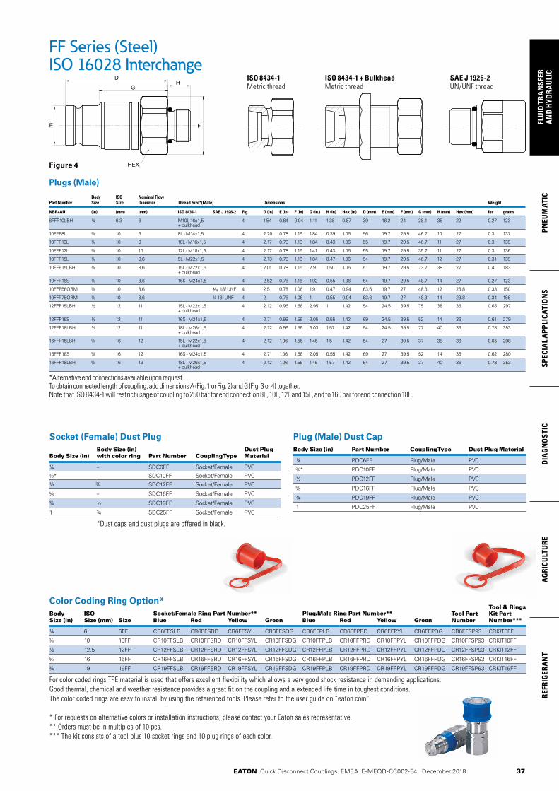
37
PNEU
MAT
ICSP
ECIA
L A
PPLI
CATI
ON
SD
IAG
NO
STIC
AG
RICU
LTU
RERE
FRIG
ERA
NT
FLU
ID T
RAN
SFER
AN
D H
YDRA
ULI
C
EATON Quick Disconnect Couplings EMEA E-MEQD-CC002-E4 December 2018
FF Series (Steel)ISO 16028 Interchange
Plugs (Male) Body ISO Nominal Flow Part Number Size Size Diameter Thread Size*(Male) Dimensions Weight
NBR+AU (in) (mm) (mm) ISO 8434-1 SAE J 1926-2 Fig. D (in) E (in) F (in) G (in.) H (in) Hex (in) D (mm) E (mm) F (mm) G (mm) H (mm) Hex (mm) lbs grams
6FFP10LBH ¼ 6.3 6 M10L 16x1,5 4 1.54 0.64 0.94 1.11 1.38 0.87 39 16.2 24 28.1 35 22 0.27 123 + bulkhead
10FFP8L 10 6 8L - M14x1,5 4 2.20 0.78 1.16 1.84 0.39 1.06 56 19.7 29.5 46.7 10 27 0.3 137
10FFP10L 10 8 10L - M16x1,5 4 2.17 0.78 1.16 1.84 0.43 1.06 55 19.7 29.5 46.7 11 27 0.3 135
10FFP12L 10 10 12L - M18x1,5 4 2.17 0.78 1.16 1.41 0.43 1.06 55 19.7 29.5 35.7 11 27 0.3 136
10FFP15L 10 8,6 5L - M22x1,5 4 2.13 0.78 1.16 1.84 0.47 1.06 54 19.7 29.5 46.7 12 27 0.31 139
10FFP15LBH 10 8,6 15L - M22x1,5 4 2.01 0.78 1.16 2.9 1.50 1.06 51 19.7 29.5 73.7 38 27 0.4 183 + bulkhead
10FFP16S 10 8,6 16S - M24x1,5 4 2.52 0.78 1.16 1.92 0.55 1.06 64 19.7 29.5 48.7 14 27 0.27 123
10FFP56ORM 10 8,6 18f UNF 4 2.5 0.78 1.06 1.9 0.47 0.94 63.6 19.7 27 48.3 12 23.8 0.33 150
10FFP75ORM 10 8,6 ¾ 16f UNF 4 2. 0.78 1.06 1. 0.55 0.94 63.6 19.7 27 48.3 14 23.8 0.34 156
12FFP15LBH ½ 12 11 15L - M22x1,5 4 2.12 0.96 1.56 2.95 1 1.42 54 24.5 39.5 75 38 36 0.65 297 + bulkhead
12FFP16S ½ 12 11 16S - M24x1,5 4 2.71 0.96 1.56 2.05 0.55 1.42 69 24.5 39.5 52 14 36 0.61 279
12FFP18LBH ½ 12 11 18L - M26x1,5 4 2.12 0.96 1.56 3.03 1.57 1.42 54 24.5 39.5 77 40 36 0.78 353 + bulkhead
16FFP15LBH 16 12 15L - M22x1,5 4 2.12 1.06 1.56 1.45 1.5 1.42 54 27 39.5 37 38 36 0.65 298 + bulkhead
16FFP16S 16 12 16S - M24x1,5 4 2.71 1.06 1.56 2.05 0.55 1.42 69 27 39.5 52 14 36 0.62 280
16FFP18LBH 16 13 18L - M26x1,5 4 2.12 1.06 1.56 1.45 1.57 1.42 54 27 39.5 37 40 36 0.78 353 + bulkhead
*Alternative end connections available upon request. To obtain connected length of coupling, add dimensions A (Fig. 1 or Fig. 2) and G (Fig. 3 or 4) together. Note that ISO 8434-1 will restrict usage of coupling to 250 bar for end connection 8L, 10L, 12L and 15L, and to 160 bar for end connection 18L.
ISO 8434-1 ISO 8434-1 + Bulkhead SAE J 1926-2Metric thread Metric thread UN/UNF threadG
B
E
HEX
C
HA
HEX
F
DH
G
B
E
HEX
C
HA
HEX
F
DH
G
B
E
HEX
C
HA
HEX
F
DHG
B
E
HEX
C
HA
HEX
F
DH
Socket (Female) Dust Plug
Body Size (in)Body Size (in) with color ring Part Number Coupling Type
Dust Plug Material
¼ – SDC6FF Socket/Female PVC
* – SDC10FF Socket/Female PVC
½ SDC12FF Socket/Female PVC
– SDC16FF Socket/Female PVC
¾ ½ SDC19FF Socket/Female PVC
1 ¾ SDC25FF Socket/Female PVC
*Dust caps and dust plugs are offered in black.
Plug (Male) Dust CapBody Size (in) Part Number Coupling Type Dust Plug Material
¼ PDC6FF Plug/Male PVC
* PDC10FF Plug/Male PVC
½ PDC12FF Plug/Male PVC
PDC16FF Plug/Male PVC
¾ PDC19FF Plug/Male PVC
1 PDC25FF Plug/Male PVC
Color Coding Ring Option*Tool & Rings Kit Part Number***
Body Size (in)
ISO Size (mm)
Socket/Female Ring Part Number** Plug/Male Ring Part Number** Tool Part NumberSize Blue Red Yellow Green Blue Red Yellow Green
¼ 6 6FF CR6FFSLB CR6FFSRD CR6FFSYL CR6FFSDG CR6FFPLB CR6FFPRD CR6FFPYL CR6FFPDG CR6FFSP93 CRKIT6FF
10 10FF CR10FFSLB CR10FFSRD CR10FFSYL CR10FFSDG CR10FFPLB CR10FFPRD CR10FFPYL CR10FFPDG CR10FFSP93 CRKIT10FF
½ 12.5 12FF CR12FFSLB CR12FFSRD CR12FFSYL CR12FFSDG CR12FFPLB CR12FFPRD CR12FFPYL CR12FFPDG CR12FFSP93 CRKIT12FF
16 16FF CR16FFSLB CR16FFSRD CR16FFSYL CR16FFSDG CR16FFPLB CR16FFPRD CR16FFPYL CR16FFPDG CR16FFSP93 CRKIT16FF
¾ 19 19FF CR19FFSLB CR19FFSRD CR19FFSYL CR19FFSDG CR19FFPLB CR19FFPRD CR19FFPYL CR19FFPDG CR19FFSP93 CRKIT19FF
For color coded rings TPE material is used that offers excellent flexibility which allows a very good shock resistance in demanding applications. Good thermal, chemical and weather resistance provides a great fit on the coupling and a extended life time in toughest conditions. The color coded rings are easy to install by using the referenced tools. Please refer to the user guide on “eaton.com”
* For requests on alternative colors or installation instructions, please contact your Eaton sales representative.** Orders must be in multiples of 10 pcs. *** The kit consists of a tool plus 10 socket rings and 10 plug rings of each color.
Figure 4

38
FLUID
TRAN
SFERA
ND
HYD
RAU
LICPN
EUM
ATICSPECIA
L APPLICATIO
NS
DIA
GN
OSTIC
AG
RICULTU
REREFRIG
ERAN
T
EATON Quick Disconnect Couplings EMEA E-MEQD-CC002-E4 December 2018
Physical Characteristics Maximum Operating Pressure Minimum Burst Pressure ISO Coupling Plug/ Socket/ Plug/ Socket/ Fluid Air Size* Size Connected Male Half Female Half Connected Male Half Female Half Rated Flow** Loss Inclusion Force to Connect(mm) (in) (bar) (psi) (bar) (psi) (bar) (psi) (bar) (psi) (bar) (psi) (bar) (psi) (lpm) (gpm) ml-cc. ml-cc. N Lbs
6.3 ¼ 250 3,625 250 3,625 250 3,625 2,335 33,858 1,640 23,780 1,330 19,285 17 4.49 0.004 0.007 80 18.0
10 250 3,625 250 3,625 250 3,625 1,672 24,244 1,664 24,128 845 12,253 29 7.66 0.006 0.010 140 31.5
12 ½ 250 3,625 250 3,625 250 3,625 1,679 24,346 997 14,457 993 14,399 55 14.53 0.012 0.013 195 43.8
16 250 3,625 250 3,625 250 3,625 1,190 17,255 950 13,775 880 12,760 67 17.70 0.016 0.030 205 46.1
19 ¾ 250 3,625 250 3,625 250 3,625 1,370 19,865 882 12,789 845 12,253 105 27.74 0.034 0.015 215 48.3
25 1 250 3,625 250 3,625 250 3,625 1,690 24,505 1,000 14,500 850 12,325 177 46.76 0.032 0.033 260 58.5
- 1"½ 250 3,625 250 3,625 250 3,625 750 10,875 750 10,875 750 10,875 450 118.9 0.265 0.445 385 86.6
- 2" 175 2,535 175 2,535 175 2,535 525 7,610 525 7,610 525 7,610 700 184.9 0.390 0.260 375 84.3
* The ISO size corresponds to the internal diameter of the hose or the external diameter of the rigid tube (as defined in ISO 4397 Standard) ** Indicated values refer to a 1 bar/14.5 psi pressure drop
Seal Elastomer Data*
ISO Size (6FF to 25FF) Non-ISO Size (40FF and 50FF) Maximum Operation Maximum Operation Seal Elastomer P/N Code Temperature Range Temperature Range
NBR (Nitrile) + AU (Polyurethane) - -25°C +100°C/-13°F +212°F on request
FKM -143 -20°C +200°C/-4°F +392°F -20°C +200°C/-4°F +392°F
EPDM (Ethylene-Propylene) -192 -40°C +150°C/-40°F +302°F on request
*For reference only, based on Eaton recommended temperatures. Contact Eaton technical support for further information on fluid compatibility.
Product Features
MLFF Series (Stainless Steel)ISO 16028 Flat Face/Dry Break
Applications & Markets• Construction• Agriculture• Iron and Steel Industry• Railway• Oil and Gas• Marine• Material Handling• General Hydraulic
Applications
Eaton’s MLFF Series stainless steel coupling is a flat face dry break coupling used for hydraulic applications. The MLFF Series interchanges with all ISO 16028 profiles. Due to its stainless steel design, it is corrosion resistant and can handle aggressive environments.
• Designed and manufactured under Article 4.3 of the European Pressure Equipment Directive PED 2014/68/EU
• Safety sleeve lock prevents accidental disconnections
• Push to connect with double shut-off valving
• Shock resistant color coding ring option available in sizes 10FF, 12FF, 16FF and 19FF to prevent accidental crossing of lines
• Resistant to aggressive environments and corrosion
• Utilize FF Series dust caps
• Standard body material: 316L Stainless steel corrosion resistant
• Alternative end connections available upon request
• Standard seal material: FKM, EPDM, NBR+AU, HNBR (upon request)
Flow Data
0.264 2.64 26.4 2641.45
14.5
0.1
1
1 10 100 1000
Flow rate (gpm)
Pres
sure
dro
p (P
SI)
Pres
sure
dro
p (b
ar)
Flow rate (l/min)
72,5 58,0
43,5
29,0
2,90
4,35
7,25
5 4
3
2
0,2
0,3
0,5
Hydraulic Oil viscosity: 30 Cst at 40°C/104°F
European Pressure Equipment DirectiveAll couplings are designed and manufactured under Article 4.3 of the European Pressure Equipment Directive PED 2014/68/EU. Couplings with nominal diameters greater than 25 mm should not be used to convey gases in Group 1 (hazardous). Maximum Operating Pressure
Non hazardous liquids Group 2 Non hazardous gases Group 2 Hazardous liquids Group 1
Coupling Size
Nominal Flow Diameter
Plug & Connected Socket
Plug & Connected Socket
Plug & Connected Socket
(in) bar (psi) bar (psi) bar (psi) bar (psi) bar (psi) bar (psi)
1 ½ 30.1 300 4350 270 3915 300 4350 270 3915 66 955 66 955
2 39.2 300 4350 225 3260 25 360 25 360 50 725 50 725
* Nominal diameters over 25mm should not be used to convey gases in group 1 (PED 2014/68/EU)
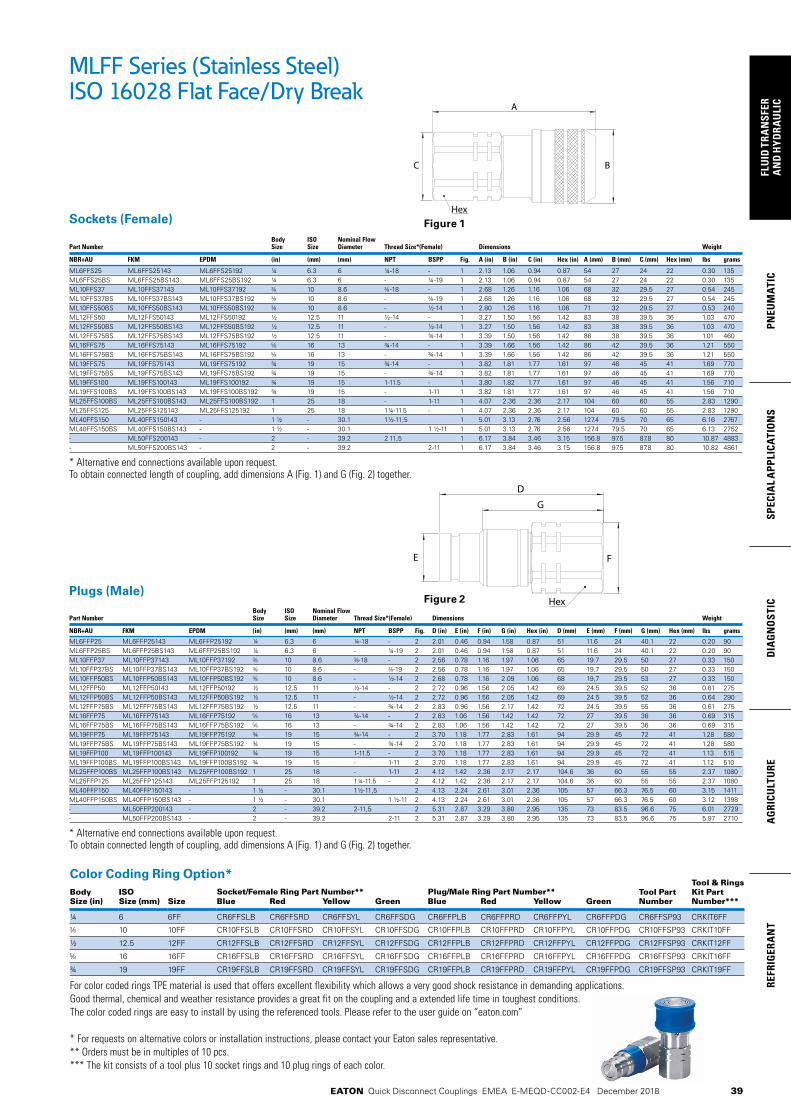
39
PNEU
MAT
ICSP
ECIA
L A
PPLI
CATI
ON
SD
IAG
NO
STIC
AG
RICU
LTU
RERE
FRIG
ERA
NT
FLU
ID T
RAN
SFER
AN
D H
YDRA
ULI
C
EATON Quick Disconnect Couplings EMEA E-MEQD-CC002-E4 December 2018
Color Coding Ring Option*Tool & Rings Kit Part Number***
Body Size (in)
ISO Size (mm)
Socket/Female Ring Part Number** Plug/Male Ring Part Number** Tool Part NumberSize Blue Red Yellow Green Blue Red Yellow Green
¼ 6 6FF CR6FFSLB CR6FFSRD CR6FFSYL CR6FFSDG CR6FFPLB CR6FFPRD CR6FFPYL CR6FFPDG CR6FFSP93 CRKIT6FF
10 10FF CR10FFSLB CR10FFSRD CR10FFSYL CR10FFSDG CR10FFPLB CR10FFPRD CR10FFPYL CR10FFPDG CR10FFSP93 CRKIT10FF
½ 12.5 12FF CR12FFSLB CR12FFSRD CR12FFSYL CR12FFSDG CR12FFPLB CR12FFPRD CR12FFPYL CR12FFPDG CR12FFSP93 CRKIT12FF
16 16FF CR16FFSLB CR16FFSRD CR16FFSYL CR16FFSDG CR16FFPLB CR16FFPRD CR16FFPYL CR16FFPDG CR16FFSP93 CRKIT16FF
¾ 19 19FF CR19FFSLB CR19FFSRD CR19FFSYL CR19FFSDG CR19FFPLB CR19FFPRD CR19FFPYL CR19FFPDG CR19FFSP93 CRKIT19FF
For color coded rings TPE material is used that offers excellent flexibility which allows a very good shock resistance in demanding applications. Good thermal, chemical and weather resistance provides a great fit on the coupling and a extended life time in toughest conditions. The color coded rings are easy to install by using the referenced tools. Please refer to the user guide on “eaton.com”
* For requests on alternative colors or installation instructions, please contact your Eaton sales representative.** Orders must be in multiples of 10 pcs. *** The kit consists of a tool plus 10 socket rings and 10 plug rings of each color.
Sockets (Female) Body ISO Nominal Flow Part Number Size Size Diameter Thread Size*(Female) Dimensions Weight
NBR+AU FKM EPDM (in) (mm) (mm) NPT BSPP Fig. A (in) B (in) C (in) Hex (in) A (mm) B (mm) C (mm) Hex (mm) lbs grams
ML6FFS25 ML6FFS25143 ML6FFS25192 ¼ 6.3 6 ¼-18 - 1 2.13 1.06 0.94 0.87 54 27 24 22 0.30 135ML6FFS25BS ML6FFS25BS143 ML6FFS25BS192 ¼ 6.3 6 - ¼-19 1 2.13 1.06 0.94 0.87 54 27 24 22 0.30 135ML10FFS37 ML10FFS37143 ML10FFS37192 10 8.6 -18 - 1 2.68 1.26 1.16 1.06 68 32 29.5 27 0.54 245ML10FFS37BS ML10FFS37BS143 ML10FFS37BS192 10 8.6 - -19 1 2.68 1.26 1.16 1.06 68 32 29.5 27 0.54 245ML10FFS50BS ML10FFS50BS143 ML10FFS50BS192 10 8.6 - ½-14 1 2.80 1.26 1.16 1.06 71 32 29.5 27 0.53 240ML12FFS50 ML12FFS50143 ML12FFS50192 ½ 12.5 11 ½-14 - 1 3.27 1.50 1.56 1.42 83 38 39.5 36 1.03 470ML12FFS50BS ML12FFS50BS143 ML12FFS50BS192 ½ 12.5 11 - ½-14 1 3.27 1.50 1.56 1.42 83 38 39.5 36 1.03 470ML12FFS75BS ML12FFS75BS143 ML12FFS75BS192 ½ 12.5 11 - ¾-14 1 3.39 1.50 1.56 1.42 86 38 39.5 36 1.01 460ML16FFS75 ML16FFS75143 ML16FFS75192 16 13 ¾-14 - 1 3.39 1.66 1.56 1.42 86 42 39.5 36 1.21 550ML16FFS75BS ML16FFS75BS143 ML16FFS75BS192 16 13 - ¾-14 1 3.39 1.66 1.56 1.42 86 42 39.5 36 1.21 550ML19FFS75 ML19FFS75143 ML19FFS75192 ¾ 19 15 ¾-14 - 1 3.82 1.81 1.77 1.61 97 46 45 41 1.69 770ML19FFS75BS ML19FFS75BS143 ML19FFS75BS192 ¾ 19 15 - ¾-14 1 3.82 1.81 1.77 1.61 97 46 45 41 1.69 770ML19FFS100 ML19FFS100143 ML19FFS100192 ¾ 19 15 1-11.5 - 1 3.80 1.82 1.77 1.61 97 46 45 41 1.56 710ML19FFS100BS ML19FFS100BS143 ML19FFS100BS192 ¾ 19 15 - 1-11 1 3.82 1.81 1.77 1.61 97 46 45 41 1.56 710ML25FFS100BS ML25FFS100BS143 ML25FFS100BS192 1 25 18 - 1-11 1 4.07 2.36 2.36 2.17 104 60 60 55 2.83 1290ML25FFS125 ML25FFS125143 ML25FFS125192 1 25 18 1¼-11.5 - 1 4.07 2.36 2.36 2.17 104 60 60 55 2.83 1290ML40FFS150 ML40FFS150143 - 1 ½ - 30.1 1½-11,5 1 5.01 3.13 2.76 2.56 127.4 79.5 70 65 6.16 2767ML40FFS150BS ML40FFS150BS143 - 1 ½ - 30.1 1 ½-11 1 5.01 3.13 2.76 2.56 127.4 79.5 70 65 6.13 2752- ML50FFS200143 - 2 - 39.2 2 11,5 1 6.17 3.84 3.46 3.15 156.8 97.5 87.8 80 10.87 4883- ML50FFS200BS143 - 2 - 39.2 2-11 1 6.17 3.84 3.46 3.15 156.8 97.5 87.8 80 10.82 4861
* Alternative end connections available upon request. To obtain connected length of coupling, add dimensions A (Fig. 1) and G (Fig. 2) together.
Plugs (Male) Body ISO Nominal Flow Part Number Size Size Diameter Thread Size*(Female) Dimensions Weight
NBR+AU FKM EPDM (in) (mm) (mm) NPT BSPP Fig. D (in) E (in) F (in) G (in) Hex (in) D (mm) E (mm) F (mm) G (mm) Hex (mm) lbs grams
ML6FFP25 ML6FFP25143 ML6FFP25192 ¼ 6.3 6 ¼-18 - 2 2.01 0.46 0.94 1.58 0.87 51 11.6 24 40.1 22 0.20 90ML6FFP25BS ML6FFP25BS143 ML6FFP25BS192 ¼ 6.3 6 - ¼-19 2 2.01 0.46 0.94 1.58 0.87 51 11.6 24 40.1 22 0.20 90ML10FFP37 ML10FFP37143 ML10FFP37192 10 8.6 -18 - 2 2.56 0.78 1.16 1.97 1.06 65 19.7 29.5 50 27 0.33 150ML10FFP37BS ML10FFP37BS143 ML10FFP37BS192 10 8.6 - -19 2 2.56 0.78 1.16 1.97 1.06 65 19,7 29.5 50 27 0.33 150ML10FFP50BS ML10FFP50BS143 ML10FFP50BS192 10 8.6 - ½-14 2 2.68 0.78 1.16 2.09 1.06 68 19,7 29.5 53 27 0.33 150ML12FFP50 ML12FFP50143 ML12FFP50192 ½ 12.5 11 ½-14 - 2 2.72 0.96 1.56 2.05 1.42 69 24.5 39.5 52 36 0.61 275ML12FFP50BS ML12FFP50BS143 ML12FFP50BS192 ½ 12.5 11 - ½-14 2 2.72 0.96 1.56 2.05 1.42 69 24.5 39.5 52 36 0.64 290ML12FFP75BS ML12FFP75BS143 ML12FFP75BS192 ½ 12.5 11 - ¾-14 2 2.83 0.96 1.56 2.17 1.42 72 24.5 39.5 55 36 0.61 275ML16FFP75 ML16FFP75143 ML16FFP75192 16 13 ¾-14 - 2 2.83 1.06 1.56 1.42 1.42 72 27 39.5 36 36 0.69 315ML16FFP75BS ML16FFP75BS143 ML16FFP75BS192 16 13 - ¾-14 2 2.83 1.06 1.56 1.42 1.42 72 27 39.5 36 36 0.69 315ML19FFP75 ML19FFP75143 ML19FFP75192 ¾ 19 15 ¾-14 - 2 3.70 1.18 1.77 2.83 1.61 94 29.9 45 72 41 1.28 580ML19FFP75BS ML19FFP75BS143 ML19FFP75BS192 ¾ 19 15 - ¾-14 2 3.70 1.18 1.77 2.83 1.61 94 29.9 45 72 41 1.28 580ML19FFP100 ML19FFP100143 ML19FFP100192 ¾ 19 15 1-11.5 - 2 3.70 1.18 1.77 2.83 1.61 94 29.9 45 72 41 1.13 515ML19FFP100BS ML19FFP100BS143 ML19FFP100BS192 ¾ 19 15 - 1-11 2 3.70 1.18 1.77 2.83 1.61 94 29.9 45 72 41 1.12 510ML25FFP100BS ML25FFP100BS143 ML25FFP100BS192 1 25 18 - 1-11 2 4.12 1.42 2.36 2.17 2.17 104.6 36 60 55 55 2.37 1080ML25FFP125 ML25FFP125143 ML25FFP125192 1 25 18 1¼-11.5 - 2 4.12 1.42 2.36 2.17 2.17 104.6 36 60 55 55 2.37 1080ML40FFP150 ML40FFP150143 - 1 ½ - 30.1 1½-11,5 2 4.13 2.24 2.61 3.01 2.36 105 57 66.3 76.5 60 3.15 1411ML40FFP150BS ML40FFP150BS143 - 1 ½ - 30.1 1 ½-11 2 4.13 2.24 2.61 3.01 2.36 105 57 66.3 76.5 60 3.12 1398- ML50FFP200143 - 2 - 39.2 2-11,5 2 5.31 2.87 3.29 3.80 2.95 135 73 83.5 96.6 75 6.01 2729- ML50FFP200BS143 - 2 - 39.2 2-11 2 5.31 2.87 3.29 3.80 2.95 135 73 83.5 96.6 75 5.97 2710
* Alternative end connections available upon request. To obtain connected length of coupling, add dimensions A (Fig. 1) and G (Fig. 2) together.
Figure 2
Figure 1
MLFF Series (Stainless Steel)ISO 16028 Flat Face/Dry Break

40
FLUID
TRAN
SFERA
ND
HYD
RAU
LICPN
EUM
ATICSPECIA
L APPLICATIO
NS
DIA
GN
OSTIC
AG
RICULTU
REREFRIG
ERAN
T
EATON Quick Disconnect Couplings EMEA E-MEQD-CC002-E4 December 2018
Flow rate (I/min)
Pres
sure
dro
p (b
ar)
Pres
sure
dro
p (b
ar)
Flow rate (gpm)Test Fluid: Oil viscosity 30 Cst at 40˚C/104˚F
Eaton’s FFCUP Series plug/male coupling is an ISO 16028 standard interchange. The flush face design prevents fluid loss on disconnection and air inclusion on connection guaranteeing excellent flow capability. An integrated patented system allows the FFCUP Series plug to be connected to a socket/female half coupling under 350 bar (5075 psi) residual pressure.
Product Features
FFCUP SeriesISO 16028 Connect Under Pressure Flat Face Plug/Male
• The plug can be connected against 350 bar/5075 psi residual pressure to sockets/females meeting ISO 16028 standard requirements.
• Plug only is under pressure while connected
• During the connection phase, the socket must not be under pressure
• Disconnection under pressure is strictly forbidden
• Connection under pressure may require a few seconds: the force to connect must be maintained during this lapse of time
Connect Under Pressure Operating Guidelines
Seal Elastomer Data*
Seal Elastomer Max. Operation Temperature Range
NBR (Nitrile) + AU (Polyurethane) -25°C +100°C/-13°F +212°F
* For reference only, based on Eaton recommended temperatures. Contact Eaton technical support for further information on fluid compatibility
Applications & Markets• Connection to Hydraulic
pumps, jacks, distributors and accessories
• Hydraulic Circuits• Material Handling• Construction• Agriculture• Iron and Steel Industry• Railway• Industrial Plants
Flow Data
Physical Characteristics
Body Size
ISO Size*
Nominal Flow Diameter
Max. Operating Pressure
Min. Burst Pressure
Rated Flow**
Air Inclusion
Fluid Loss
Force to Connect
(in) (mm) (mm) (bar) (psi) (bar) (psi) (lpm) (gpm) ml-cc. ml-cc. N lbf
3/8 10 8.6 350 5,075 1,400 20,300 29.4 7.76 0.010 0.006 350 79
1/2 12.5 11 350 5,075 1,400 20,300 46.8 12.36 0.013 0.012 270 60.7
* The ISO size corresponds to the internal diameter of the hose or the external diameter of the rigid tube(as defined in ISO 4397 Standard) ** Indicated values refer to a 1 bar/14.5 psi pressure drop
• Designed and manufactured in accordance with Article 4.3 of the European Pressure Equipment Directive PED 2014/68/EU
• Meets dimensional requirements of ISO 16028
• Push to connect
• Connect under residual pressure
• Shock resistant color coding ring option available to prevent accidental crossing of lines
• Standard Material: High-resistant carbon steel with Guardian SealTM plating, a whole new level of corrosion resistance with minimum 720 hours RR protection
• Guardian SealTM plating:
• Nickel-free
• Solvent-free
• Meets Global RoHS, ELV and REACH requirements
• Alternative end connections available upon request
• Standard seal material: NBR (Nitrile) + AU (Polyurethane)
• Utilize FF Series dust caps
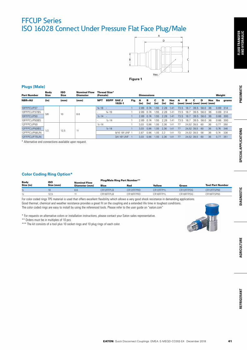
41
PNEU
MAT
ICSP
ECIA
L A
PPLI
CATI
ON
SD
IAG
NO
STIC
AG
RICU
LTU
RERE
FRIG
ERA
NT
FLU
ID T
RAN
SFER
AN
D H
YDRA
ULI
C
EATON Quick Disconnect Couplings EMEA E-MEQD-CC002-E4 December 2018
Color Coding Ring Option*
Body Size (in)
ISO Size (mm)
Nominal Flow Diameter (mm)
Plug/Male Ring Part Number**
Blue Red Yellow Green Tool Part Number
10 8.6 CR12FFPLB CR12FFPRD CR12FFPYL CR12FFPDG CR12FFSP93
½ 12,5 11 CR16FFPLB CR16FFPRD CR16FFPYL CR16FFPDG CR16FFSP93
For color coded rings TPE material is used that offers excellent flexibility which allows a very good shock resistance in demanding applications. Good thermal, chemical and weather resistance provides a great fit on the coupling and a extended life time in toughest conditions. The color coded rings are easy to install by using the referenced tools. Please refer to the user guide on “eaton.com”
* For requests on alternative colors or installation instructions, please contact your Eaton sales representative.** Orders must be in multiples of 10 pcs. *** The kit consists of a tool plus 10 socket rings and 10 plug rings of each color.
FFCUP SeriesISO 16028 Connect Under Pressure Flat Face Plug/Male
Plugs (Male)
Part NumberBody Size
ISO Size
Nominal Flow Diameter
Thread Size* (Female) Dimensions Weight
NBR+AU (in) (mm) (mm) NPT BSPP SAE J 1926-1
Fig. A (in)
B (in)
C (in)
D (in)
Hex (in)
A (mm)
B (mm)
C (mm)
D (mm)
Hex (mm)
lbs grams
10FFPCUP37
3/8 10 8.6
-18 - 1 2.89 0.74 1.55 2.28 1.41 73.5 18.7 39.5 58.0 36 0.69 31410FFPCUP37BS - -19 1 2.89 0.74 1.55 2.28 1.41 73.5 18.7 39.5 58.0 36 0.69 314
10FFPCUP50 ½-14 - 1 2.89 0.74 1.55 2.28 1.41 73.5 18.7 39.5 58.0 36 0.66 300
10FFPCUP50BS - ½-14 1 2.89 0.74 1.55 2.28 1.41 73.5 18.7 39.5 58.0 36 0.66 300
12FFPCUP50
1/2 12,5 11
½-14 1 3,03 0,96 1,55 2,36 1.41 77 24,52 39,5 60 36 0,77 350
12FFPCUP50BS ½-14 1 3,03 0,96 1,55 2,36 1.41 77 24,52 39,5 60 36 0,76 346
12FFPCUP56UN 9/16 18f UNF 1 2,87 0,96 1,55 2,2 1.41 73 24,52 39,5 56 36 0,74 336
12FFPCUP75UN 3/4 16f UNF 1 3,03 0,96 1,55 2,36 1.41 77 24,52 39,5 60 36 0,77 351
* Alternative end connections available upon request.
Figure 1
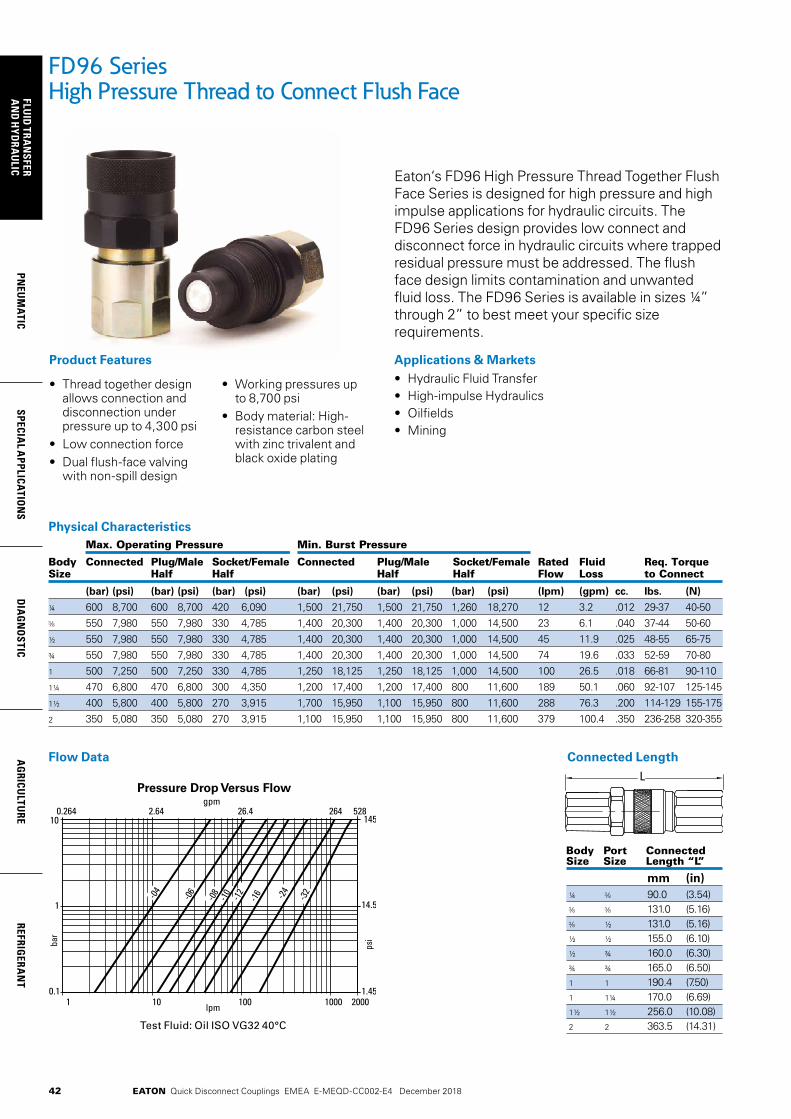
42
FLUID
TRAN
SFERA
ND
HYD
RAU
LICPN
EUM
ATICSPECIA
L APPLICATIO
NS
DIA
GN
OSTIC
AG
RICULTU
REREFRIG
ERAN
T
EATON Quick Disconnect Couplings EMEA E-MEQD-CC002-E4 December 2018
FD96 SeriesHigh Pressure Thread to Connect Flush Face
Eaton‘s FD96 High Pressure Thread Together Flush Face Series is designed for high pressure and high impulse applications for hydraulic circuits. The FD96 Series design provides low connect and disconnect force in hydraulic circuits where trapped residual pressure must be addressed. The flush face design limits contamination and unwanted fluid loss. The FD96 Series is available in sizes ¼” through 2” to best meet your specific size requirements.
Applications & Markets• Hydraulic Fluid Transfer• High-impulse Hydraulics• Oilfields• Mining
• Thread together design allows connection and disconnection under pressure up to 4,300 psi
• Low connection force• Dual flush-face valving
with non-spill design
• Working pressures up to 8,700 psi
• Body material: High- resistance carbon steel with zinc trivalent and black oxide plating
Product Features
Flow Data Connected Length
Body Port Connected Size Size Length “L”
mm (in) ¼ 90.0 (3.54) 131.0 (5.16) ½ 131.0 (5.16) ½ ½ 155.0 (6.10) ½ ¾ 160.0 (6.30) ¾ ¾ 165.0 (6.50) 1 1 190.4 (7.50) 1 1¼ 170.0 (6.69) 1½ 1½ 256.0 (10.08) 2 2 363.5 (14.31)
L
Physical Characteristics Max. Operating Pressure Min. Burst Pressure
Body Connected Plug/Male Socket/Female Connected Plug/Male Socket/Female Rated Fluid Req. Torque Size Half Half Half Half Flow Loss to Connect
(bar) (psi) (bar) (psi) (bar) (psi) (bar) (psi) (bar) (psi) (bar) (psi) (lpm) (gpm) cc. lbs. (N)
¼ 600 8,700 600 8,700 420 6,090 1,500 21,750 1,500 21,750 1,260 18,270 12 3.2 .012 29-37 40-50 550 7,980 550 7,980 330 4,785 1,400 20,300 1,400 20,300 1,000 14,500 23 6.1 .040 37-44 50-60
½ 550 7,980 550 7,980 330 4,785 1,400 20,300 1,400 20,300 1,000 14,500 45 11.9 .025 48-55 65-75¾ 550 7,980 550 7,980 330 4,785 1,400 20,300 1,400 20,300 1,000 14,500 74 19.6 .033 52-59 70-801 500 7,250 500 7,250 330 4,785 1,250 18,125 1,250 18,125 1,000 14,500 100 26.5 .018 66-81 90-1101¼ 470 6,800 470 6,800 300 4,350 1,200 17,400 1,200 17,400 800 11,600 189 50.1 .060 92-107 125-1451½ 400 5,800 400 5,800 270 3,915 1,700 15,950 1,100 15,950 800 11,600 288 76.3 .200 114-129 155-1752 350 5,080 350 5,080 270 3,915 1,100 15,950 1,100 15,950 800 11,600 379 100.4 .350 236-258 320-355
Pressure Drop Versus Flow Pressure Drop Versus FlowFD99FD96
Pressure Drop Versus FlowFD83 Pressure Drop Versus FlowFD89
1 10 100 1000 20000.1
1
10
bar
lpm
0.264 2.64 26.4 264 528
1.45
14.5
145
gpm
psi
40 100 200 3000.01
0.1
0.5
bar
lpm
10.56 26.4 52.8 79.2
0.145
1.45
7.25
gpm
psi
1 10 100 1000 40000.1
1
10
bar
lpm
0.264 2.64 26.4 264 1056
1.45
14.5
145
gpm
psi
1 10 100 1000 20000.1
1
10
bar
lpm
0.264 2.64 26.4 264 528
1.45
14.5
145
psi
gpm
-04
-06
-06
-08
-08
-10
-10
-12
-12
-16
-16
-20
-24
-24
-32
-16
-04
-06
-08
-10
-12
-16 -24
-32-04
Test Fluid: Oil ISO VG32 40°C
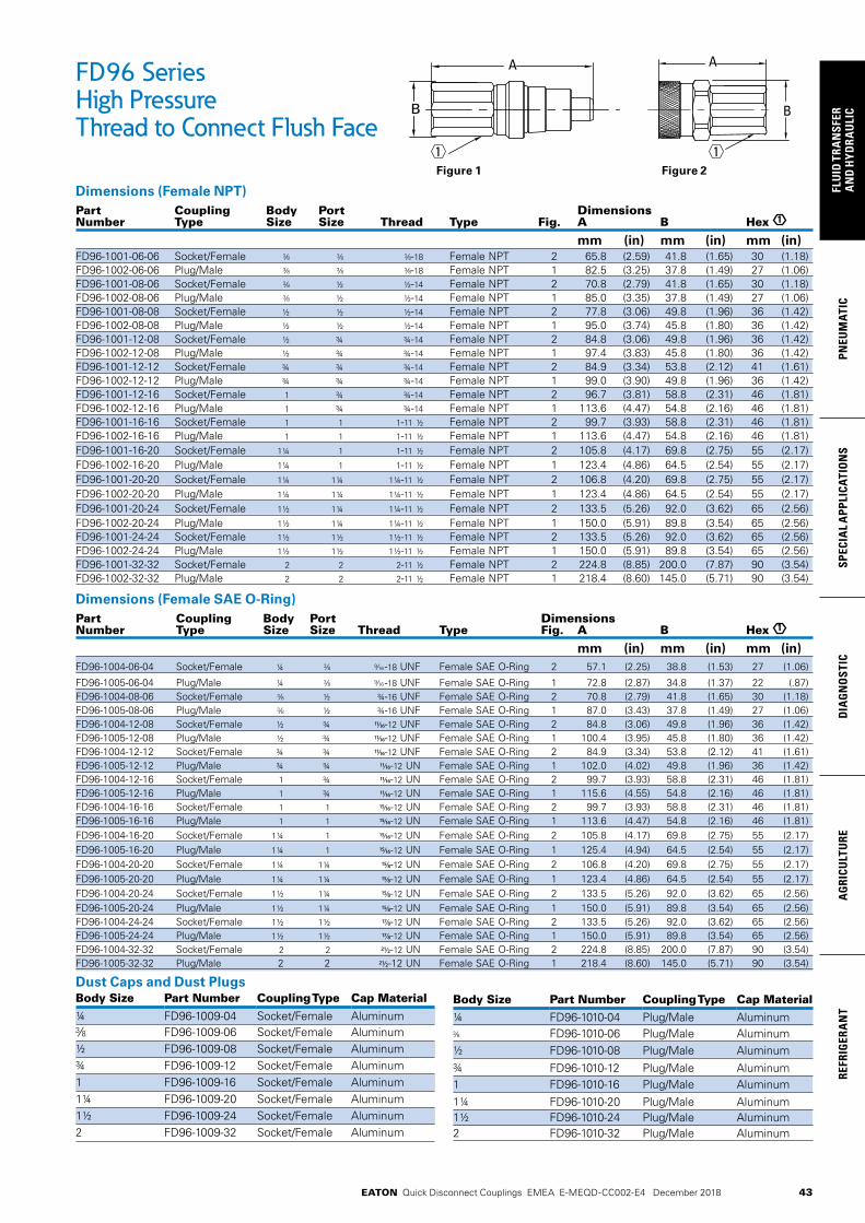
43
PNEU
MAT
ICSP
ECIA
L A
PPLI
CATI
ON
SD
IAG
NO
STIC
AG
RICU
LTU
RERE
FRIG
ERA
NT
FLU
ID T
RAN
SFER
AN
D H
YDRA
ULI
C
EATON Quick Disconnect Couplings EMEA E-MEQD-CC002-E4 December 2018
Body Size Part Number Coupling Type Cap Material¼ FD96-1009-04 Socket/Female Aluminum
FD96-1009-06 Socket/Female Aluminum½ FD96-1009-08 Socket/Female Aluminum¾ FD96-1009-12 Socket/Female Aluminum1 FD96-1009-16 Socket/Female Aluminum1¼ FD96-1009-20 Socket/Female Aluminum1½ FD96-1009-24 Socket/Female Aluminum2 FD96-1009-32 Socket/Female Aluminum
Dimensions (Female NPT)Part Coupling Body Port Dimensions Number Type Size Size Thread Type Fig. A B Hex 1
mm (in) mm (in) mm (in) FD96-1001-06-06 Socket/Female -18 Female NPT 2 65.8 (2.59) 41.8 (1.65) 30 (1.18)FD96-1002-06-06 Plug/Male -18 Female NPT 1 82.5 (3.25) 37.8 (1.49) 27 (1.06)FD96-1001-08-06 Socket/Female ½ ½-14 Female NPT 2 70.8 (2.79) 41.8 (1.65) 30 (1.18)FD96-1002-08-06 Plug/Male ½ ½-14 Female NPT 1 85.0 (3.35) 37.8 (1.49) 27 (1.06)FD96-1001-08-08 Socket/Female ½ ½ ½-14 Female NPT 2 77.8 (3.06) 49.8 (1.96) 36 (1.42)FD96-1002-08-08 Plug/Male ½ ½ ½-14 Female NPT 1 95.0 (3.74) 45.8 (1.80) 36 (1.42)FD96-1001-12-08 Socket/Female ½ ¾ ¾-14 Female NPT 2 84.8 (3.06) 49.8 (1.96) 36 (1.42)FD96-1002-12-08 Plug/Male ½ ¾ ¾-14 Female NPT 1 97.4 (3.83) 45.8 (1.80) 36 (1.42)FD96-1001-12-12 Socket/Female ¾ ¾ ¾-14 Female NPT 2 84.9 (3.34) 53.8 (2.12) 41 (1.61)FD96-1002-12-12 Plug/Male ¾ ¾ ¾-14 Female NPT 1 99.0 (3.90) 49.8 (1.96) 36 (1.42)FD96-1001-12-16 Socket/Female 1 ¾ ¾-14 Female NPT 2 96.7 (3.81) 58.8 (2.31) 46 (1.81)FD96-1002-12-16 Plug/Male 1 ¾ ¾-14 Female NPT 1 113.6 (4.47) 54.8 (2.16) 46 (1.81)FD96-1001-16-16 Socket/Female 1 1 1-11 ½ Female NPT 2 99.7 (3.93) 58.8 (2.31) 46 (1.81)FD96-1002-16-16 Plug/Male 1 1 1-11 ½ Female NPT 1 113.6 (4.47) 54.8 (2.16) 46 (1.81)FD96-1001-16-20 Socket/Female 1¼ 1 1-11 ½ Female NPT 2 105.8 (4.17) 69.8 (2.75) 55 (2.17)FD96-1002-16-20 Plug/Male 1¼ 1 1-11 ½ Female NPT 1 123.4 (4.86) 64.5 (2.54) 55 (2.17)FD96-1001-20-20 Socket/Female 1¼ 1¼ 1¼-11 ½ Female NPT 2 106.8 (4.20) 69.8 (2.75) 55 (2.17)FD96-1002-20-20 Plug/Male 1¼ 1¼ 1¼-11 ½ Female NPT 1 123.4 (4.86) 64.5 (2.54) 55 (2.17)FD96-1001-20-24 Socket/Female 1½ 1¼ 1¼-11 ½ Female NPT 2 133.5 (5.26) 92.0 (3.62) 65 (2.56)FD96-1002-20-24 Plug/Male 1½ 1¼ 1¼-11 ½ Female NPT 1 150.0 (5.91) 89.8 (3.54) 65 (2.56)FD96-1001-24-24 Socket/Female 1½ 1½ 1½-11 ½ Female NPT 2 133.5 (5.26) 92.0 (3.62) 65 (2.56)FD96-1002-24-24 Plug/Male 1½ 1½ 1½-11 ½ Female NPT 1 150.0 (5.91) 89.8 (3.54) 65 (2.56)FD96-1001-32-32 Socket/Female 2 2 2-11 ½ Female NPT 2 224.8 (8.85) 200.0 (7.87) 90 (3.54)FD96-1002-32-32 Plug/Male 2 2 2-11 ½ Female NPT 1 218.4 (8.60) 145.0 (5.71) 90 (3.54)
Dimensions (Female SAE O-Ring)Part Coupling Body Port Dimensions Number Type Size Size Thread Type Fig. A B Hex 1
mm (in) mm (in) mm (in)FD96-1004-06-04 Socket/Female ¼ -18 UNF Female SAE O-Ring 2 57.1 (2.25) 38.8 (1.53) 27 (1.06)
FD96-1005-06-04 Plug/Male ¼ -18 UNF Female SAE O-Ring 1 72.8 (2.87) 34.8 (1.37) 22 (.87)FD96-1004-08-06 Socket/Female ½ ¾-16 UNF Female SAE O-Ring 2 70.8 (2.79) 41.8 (1.65) 30 (1.18)FD96-1005-08-06 Plug/Male ½ ¾-16 UNF Female SAE O-Ring 1 87.0 (3.43) 37.8 (1.49) 27 (1.06)FD96-1004-12-08 Socket/Female ½ ¾ 11/16-12 UNF Female SAE O-Ring 2 84.8 (3.06) 49.8 (1.96) 36 (1.42)FD96-1005-12-08 Plug/Male ½ ¾ 11/16-12 UNF Female SAE O-Ring 1 100.4 (3.95) 45.8 (1.80) 36 (1.42)FD96-1004-12-12 Socket/Female ¾ ¾ 11/16-12 UNF Female SAE O-Ring 2 84.9 (3.34) 53.8 (2.12) 41 (1.61)FD96-1005-12-12 Plug/Male ¾ ¾ 11/16-12 UN Female SAE O-Ring 1 102.0 (4.02) 49.8 (1.96) 36 (1.42)FD96-1004-12-16 Socket/Female 1 ¾ 11/16-12 UN Female SAE O-Ring 2 99.7 (3.93) 58.8 (2.31) 46 (1.81)FD96-1005-12-16 Plug/Male 1 ¾ 11/16-12 UN Female SAE O-Ring 1 115.6 (4.55) 54.8 (2.16) 46 (1.81)FD96-1004-16-16 Socket/Female 1 1 15/16-12 UN Female SAE O-Ring 2 99.7 (3.93) 58.8 (2.31) 46 (1.81)FD96-1005-16-16 Plug/Male 1 1 15/16-12 UN Female SAE O-Ring 1 113.6 (4.47) 54.8 (2.16) 46 (1.81)FD96-1004-16-20 Socket/Female 1¼ 1 15/16-12 UN Female SAE O-Ring 2 105.8 (4.17) 69.8 (2.75) 55 (2.17)FD96-1005-16-20 Plug/Male 1¼ 1 15/16-12 UN Female SAE O-Ring 1 125.4 (4.94) 64.5 (2.54) 55 (2.17)FD96-1004-20-20 Socket/Female 1¼ 1¼ 15/8-12 UN Female SAE O-Ring 2 106.8 (4.20) 69.8 (2.75) 55 (2.17)FD96-1005-20-20 Plug/Male 1¼ 1¼ 15/8-12 UN Female SAE O-Ring 1 123.4 (4.86) 64.5 (2.54) 55 (2.17)FD96-1004-20-24 Socket/Female 1½ 1¼ 15/8-12 UN Female SAE O-Ring 2 133.5 (5.26) 92.0 (3.62) 65 (2.56)FD96-1005-20-24 Plug/Male 1½ 1¼ 15/8-12 UN Female SAE O-Ring 1 150.0 (5.91) 89.8 (3.54) 65 (2.56)FD96-1004-24-24 Socket/Female 1½ 1½ 17/8-12 UN Female SAE O-Ring 2 133.5 (5.26) 92.0 (3.62) 65 (2.56)FD96-1005-24-24 Plug/Male 1½ 1½ 17/8-12 UN Female SAE O-Ring 1 150.0 (5.91) 89.8 (3.54) 65 (2.56)FD96-1004-32-32 Socket/Female 2 2 21/2-12 UN Female SAE O-Ring 2 224.8 (8.85) 200.0 (7.87) 90 (3.54)FD96-1005-32-32 Plug/Male 2 2 21/2-12 UN Female SAE O-Ring 1 218.4 (8.60) 145.0 (5.71) 90 (3.54)
Dust Caps and Dust Plugs
FD96 SeriesHigh Pressure Thread to Connect Flush Face
B
A
B
A
1 1Figure 1 Figure 2
Body Size Part Number Coupling Type Cap Material¼ FD96-1010-04 Plug/Male Aluminum
FD96-1010-06 Plug/Male Aluminum½ FD96-1010-08 Plug/Male Aluminum¾ FD96-1010-12 Plug/Male Aluminum1 FD96-1010-16 Plug/Male Aluminum1¼ FD96-1010-20 Plug/Male Aluminum1½ FD96-1010-24 Plug/Male Aluminum2 FD96-1010-32 Plug/Male Aluminum
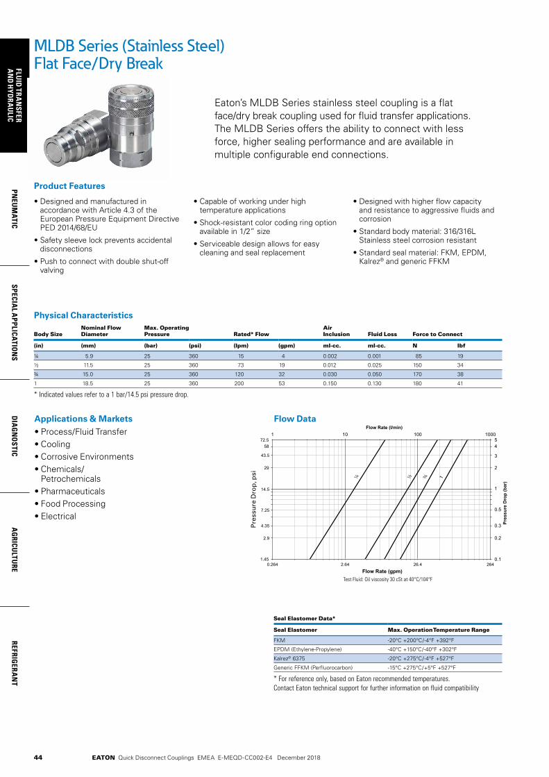
44
FLUID
TRAN
SFERA
ND
HYD
RAU
LICPN
EUM
ATICSPECIA
L APPLICATIO
NS
DIA
GN
OSTIC
AG
RICULTU
REREFRIG
ERAN
T
EATON Quick Disconnect Couplings EMEA E-MEQD-CC002-E4 December 2018
Eaton’s MLDB Series stainless steel coupling is a flat face/dry break coupling used for fluid transfer applications. The MLDB Series offers the ability to connect with less force, higher sealing performance and are available in multiple configurable end connections.
• Designed and manufactured in accordance with Article 4.3 of the European Pressure Equipment Directive PED 2014/68/EU
• Safety sleeve lock prevents accidental disconnections
• Push to connect with double shut-off valving
• Capable of working under high temperature applications
• Shock-resistant color coding ring option available in 1/2” size
• Serviceable design allows for easy cleaning and seal replacement
• Designed with higher flow capacity and resistance to aggressive fluids and corrosion
• Standard body material: 316/316L Stainless steel corrosion resistant
• Standard seal material: FKM, EPDM, Kalrez® and generic FFKM
Product Features
MLDB Series (Stainless Steel)Flat Face/Dry Break
Applications & Markets• Process/Fluid Transfer• Cooling• Corrosive Environments• Chemicals/
Petrochemicals• Pharmaceuticals• Food Processing • Electrical
Test Fluid: Oil viscosity 30 cSt at 40°C/104°FFlow Rate (gpm)
Pre
ssu
re d
rop
(P
SI)
Pre
ssu
re D
rop
(b
ar)
Flow Rate (l/min)
0.264 2.64 26.4 264 1.45
72.5
43.5
14.5
7.25
4.35
0.1
1
0.5
0.3
0.2
5 4
3
2
1 10 100 1000
58
29
2.9
¼ ½ ¾ 1
Physical Characteristics
Body SizeNominal Flow Diameter
Max. Operating Pressure Rated* Flow
Air Inclusion Fluid Loss Force to Connect
(in) (mm) (bar) (psi) (lpm) (gpm) ml-cc. ml-cc. N lbf
¼ 5.9 25 360 15 4 0.002 0.001 85 19
½ 11.5 25 360 73 19 0.012 0.025 150 34
¾ 15.0 25 360 120 32 0.030 0.050 170 38
1 18.5 25 360 200 53 0.150 0.130 180 41
* Indicated values refer to a 1 bar/14.5 psi pressure drop.
Seal Elastomer Data* Seal Elastomer Max. Operation Temperature Range
FKM -20°C +200°C/-4°F +392°F
EPDM (Ethylene-Propylene) -40°C +150°C/-40°F +302°F
Kalrez® 6375 -20°C +275°C/-4°F +527°F
Generic FFKM (Perfluorocarbon) -15°C +275°C/+5°F +527°F
* For reference only, based on Eaton recommended temperatures. Contact Eaton technical support for further information on fluid compatibility
Flow Data
Pre
ssu
re D
rop
, psi
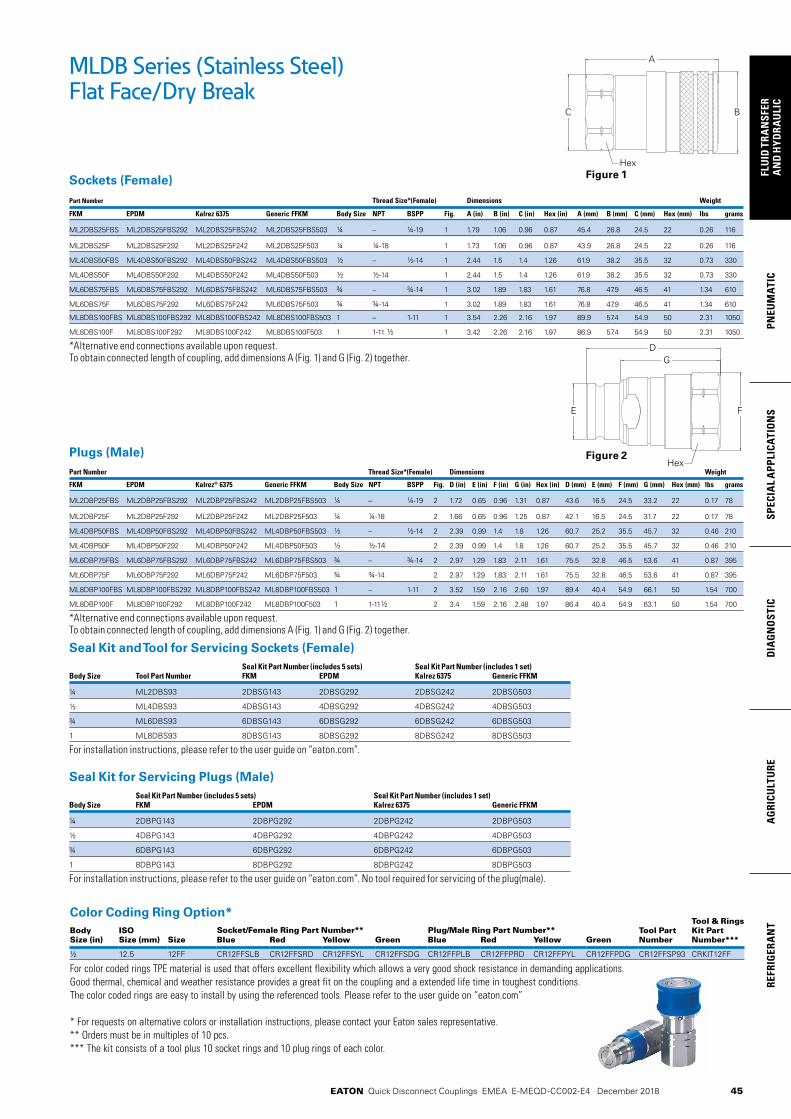
45
PNEU
MAT
ICSP
ECIA
L A
PPLI
CATI
ON
SD
IAG
NO
STIC
AG
RICU
LTU
RERE
FRIG
ERA
NT
FLU
ID T
RAN
SFER
AN
D H
YDRA
ULI
C
EATON Quick Disconnect Couplings EMEA E-MEQD-CC002-E4 December 2018
Color Coding Ring Option*Tool & Rings Kit Part Number***
Body Size (in)
ISO Size (mm)
Socket/Female Ring Part Number** Plug/Male Ring Part Number** Tool Part NumberSize Blue Red Yellow Green Blue Red Yellow Green
½ 12.5 12FF CR12FFSLB CR12FFSRD CR12FFSYL CR12FFSDG CR12FFPLB CR12FFPRD CR12FFPYL CR12FFPDG CR12FFSP93 CRKIT12FF
For color coded rings TPE material is used that offers excellent flexibility which allows a very good shock resistance in demanding applications. Good thermal, chemical and weather resistance provides a great fit on the coupling and a extended life time in toughest conditions. The color coded rings are easy to install by using the referenced tools. Please refer to the user guide on “eaton.com”
* For requests on alternative colors or installation instructions, please contact your Eaton sales representative.** Orders must be in multiples of 10 pcs. *** The kit consists of a tool plus 10 socket rings and 10 plug rings of each color.
Sockets (Female)Part Number Thread Size*(Female) Dimensions Weight
FKM EPDM Kalrez 6375 Generic FFKM Body Size NPT BSPP Fig. A (in) B (in) C (in) Hex (in) A (mm) B (mm) C (mm) Hex (mm) lbs grams
ML2DBS25FBS ML2DBS25FBS292 ML2DBS25FBS242 ML2DBS25FBS503 ¼ – ¼-19 1 1.79 1.06 0.96 0.87 45.4 26.8 24.5 22 0.26 116
ML2DBS25F ML2DBS25F292 ML2DBS25F242 ML2DBS25F503 ¼ ¼-18 1 1.73 1.06 0.96 0.87 43.9 26.8 24.5 22 0.26 116
ML4DBS50FBS ML4DBS50FBS292 ML4DBS50FBS242 ML4DBS50FBS503 ½ – ½-14 1 2.44 1.5 1.4 1.26 61.9 38.2 35.5 32 0.73 330
ML4DBS50F ML4DBS50F292 ML4DBS50F242 ML4DBS50F503 ½ ½-14 1 2.44 1.5 1.4 1.26 61.9 38.2 35.5 32 0.73 330
ML6DBS75FBS ML6DBS75FBS292 ML6DBS75FBS242 ML6DBS75FBS503 ¾ – ¾-14 1 3.02 1.89 1.83 1.61 76.8 47.9 46.5 41 1.34 610
ML6DBS75F ML6DBS75F292 ML6DBS75F242 ML6DBS75F503 ¾ ¾-14 1 3.02 1.89 1.83 1.61 76.8 47.9 46.5 41 1.34 610
ML8DBS100FBS ML8DBS100FBS292 ML8DBS100FBS242 ML8DBS100FBS503 1 – 1-11 1 3.54 2.26 2.16 1.97 89.9 57.4 54.9 50 2.31 1050
ML8DBS100F ML8DBS100F292 ML8DBS100F242 ML8DBS100F503 1 1-11 ½ 1 3.42 2.26 2.16 1.97 86.9 57.4 54.9 50 2.31 1050
*Alternative end connections available upon request. To obtain connected length of coupling, add dimensions A (Fig. 1) and G (Fig. 2) together.
Plugs (Male)Part Number Thread Size*(Female) Dimensions Weight
FKM EPDM Kalrez® 6375 Generic FFKM Body Size NPT BSPP Fig. D (in) E (in) F (in) G (in) Hex (in) D (mm) E (mm) F (mm) G (mm) Hex (mm) lbs grams
ML2DBP25FBS ML2DBP25FBS292 ML2DBP25FBS242 ML2DBP25FBS503 ¼ – ¼-19 2 1.72 0.65 0.96 1.31 0.87 43.6 16.5 24.5 33.2 22 0.17 78
ML2DBP25F ML2DBP25F292 ML2DBP25F242 ML2DBP25F503 ¼ ¼-18 2 1.66 0.65 0.96 1.25 0.87 42.1 16.5 24.5 31.7 22 0.17 78
ML4DBP50FBS ML4DBP50FBS292 ML4DBP50FBS242 ML4DBP50FBS503 ½ – ½-14 2 2.39 0.99 1.4 1.8 1.26 60.7 25.2 35.5 45.7 32 0.46 210
ML4DBP50F ML4DBP50F292 ML4DBP50F242 ML4DBP50F503 ½ ½-14 2 2.39 0.99 1.4 1.8 1.26 60.7 25.2 35.5 45.7 32 0.46 210
ML6DBP75FBS ML6DBP75FBS292 ML6DBP75FBS242 ML6DBP75FBS503 ¾ – ¾-14 2 2.97 1.29 1.83 2.11 1.61 75.5 32.8 46.5 53.6 41 0.87 395
ML6DBP75F ML6DBP75F292 ML6DBP75F242 ML6DBP75F503 ¾ ¾-14 2 2.97 1.29 1.83 2.11 1.61 75.5 32.8 46.5 53.6 41 0.87 395
ML8DBP100FBS ML8DBP100FBS292 ML8DBP100FBS242 ML8DBP100FBS503 1 – 1-11 2 3.52 1.59 2.16 2.60 1.97 89.4 40.4 54.9 66.1 50 1.54 700
ML8DBP100F ML8DBP100F292 ML8DBP100F242 ML8DBP100F503 1 1-11½ 2 3.4 1.59 2.16 2.48 1.97 86.4 40.4 54.9 63.1 50 1.54 700
*Alternative end connections available upon request. To obtain connected length of coupling, add dimensions A (Fig. 1) and G (Fig. 2) together.
Seal Kit and Tool for Servicing Sockets (Female) Seal Kit Part Number (includes 5 sets) Seal Kit Part Number (includes 1 set) Body Size Tool Part Number FKM EPDM Kalrez 6375 Generic FFKM
¼ ML2DBS93 2DBSG143 2DBSG292 2DBSG242 2DBSG503
½ ML4DBS93 4DBSG143 4DBSG292 4DBSG242 4DBSG503
¾ ML6DBS93 6DBSG143 6DBSG292 6DBSG242 6DBSG503
1 ML8DBS93 8DBSG143 8DBSG292 8DBSG242 8DBSG503
For installation instructions, please refer to the user guide on “eaton.com”.
Seal Kit for Servicing Plugs (Male) Seal Kit Part Number (includes 5 sets) Seal Kit Part Number (includes 1 set) Body Size FKM EPDM Kalrez 6375 Generic FFKM
¼ 2DBPG143 2DBPG292 2DBPG242 2DBPG503
½ 4DBPG143 4DBPG292 4DBPG242 4DBPG503
¾ 6DBPG143 6DBPG292 6DBPG242 6DBPG503
1 8DBPG143 8DBPG292 8DBPG242 8DBPG503
For installation instructions, please refer to the user guide on “eaton.com”. No tool required for servicing of the plug(male).
DG
E
Hex
F
A
C B
Hex
MLDB Series (Stainless Steel)Flat Face/Dry Break
Figure 1
Figure 2
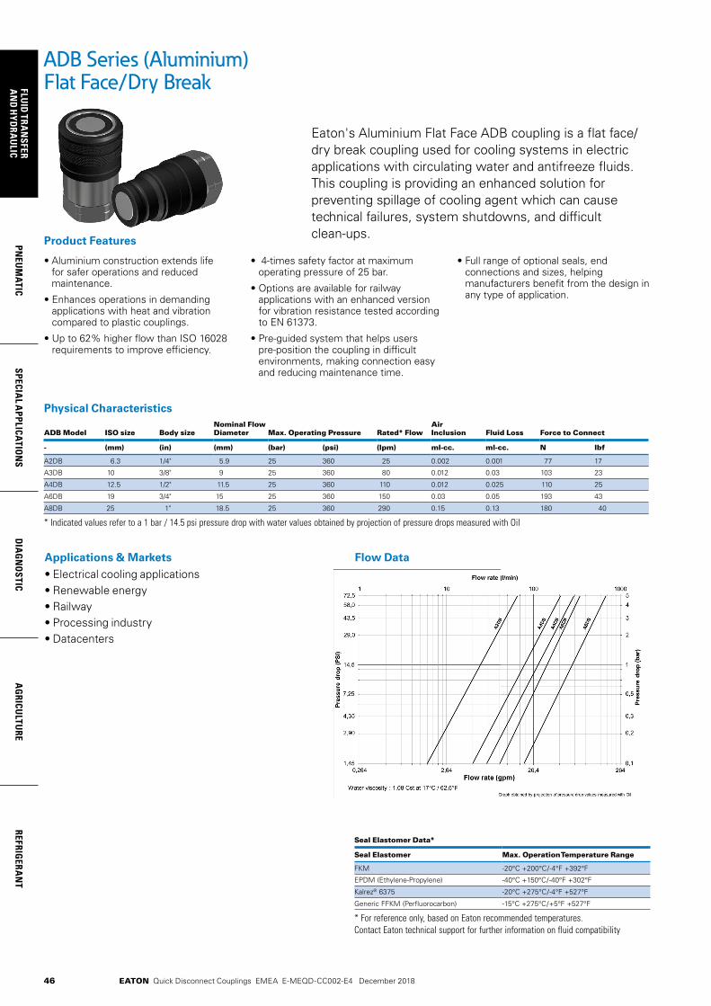
46
FLUID
TRAN
SFERA
ND
HYD
RAU
LICPN
EUM
ATICSPECIA
L APPLICATIO
NS
DIA
GN
OSTIC
AG
RICULTU
REREFRIG
ERAN
T
EATON Quick Disconnect Couplings EMEA E-MEQD-CC002-E4 December 2018
ADB Series (Aluminium)Flat Face/Dry Break
Eaton's Aluminium Flat Face ADB coupling is a flat face/dry break coupling used for cooling systems in electric applications with circulating water and antifreeze fluids. This coupling is providing an enhanced solution for preventing spillage of cooling agent which can cause technical failures, system shutdowns, and difficult clean-ups.
• Aluminium construction extends life for safer operations and reduced maintenance.
• Enhances operations in demanding applications with heat and vibration compared to plastic couplings.
• Up to 62% higher flow than ISO 16028 requirements to improve efficiency.
• 4-times safety factor at maximum operating pressure of 25 bar.
• Options are available for railway applications with an enhanced version for vibration resistance tested according to EN 61373.
• Pre-guided system that helps users pre-position the coupling in difficult environments, making connection easy and reducing maintenance time.
• Full range of optional seals, end connections and sizes, helping manufacturers benefit from the design in any type of application.
Product Features
Applications & Markets• Electrical cooling applications• Renewable energy• Railway• Processing industry• Datacenters
Physical Characteristics
ADB Model ISO size Body sizeNominal Flow Diameter Max. Operating Pressure Rated* Flow
Air Inclusion Fluid Loss Force to Connect
- (mm) (in) (mm) (bar) (psi) (lpm) ml-cc. ml-cc. N lbf
A2DB 6.3 1/4" 5.9 25 360 25 0.002 0.001 77 17
A3DB 10 3/8" 9 25 360 80 0.012 0.03 103 23
A4DB 12.5 1/2" 11.5 25 360 110 0.012 0.025 110 25
A6DB 19 3/4" 15 25 360 150 0.03 0.05 193 43
A8DB 25 1" 18.5 25 360 290 0.15 0.13 180 40
* Indicated values refer to a 1 bar / 14.5 psi pressure drop with water values obtained by projection of pressure drops measured with Oil
Seal Elastomer Data* Seal Elastomer Max. Operation Temperature Range
FKM -20°C +200°C/-4°F +392°F
EPDM (Ethylene-Propylene) -40°C +150°C/-40°F +302°F
Kalrez® 6375 -20°C +275°C/-4°F +527°F
Generic FFKM (Perfluorocarbon) -15°C +275°C/+5°F +527°F
* For reference only, based on Eaton recommended temperatures. Contact Eaton technical support for further information on fluid compatibility
Flow Data

47
PNEU
MAT
ICSP
ECIA
L A
PPLI
CATI
ON
SD
IAG
NO
STIC
AG
RICU
LTU
RERE
FRIG
ERA
NT
FLU
ID T
RAN
SFER
AN
D H
YDRA
ULI
C
EATON Quick Disconnect Couplings EMEA E-MEQD-CC002-E4 December 2018
Color Coding Ring Option*Tool & Rings Kit Part Number***
Body Size (in)
ISO Size (mm)
Socket/Female Ring Part Number** Plug/Male Ring Part Number** Tool Part NumberSize Blue Red Yellow Green Blue Red Yellow Green
½ 12.5 12FF CR12FFSLB CR12FFSRD CR12FFSYL CR12FFSDG CR12FFPLB CR12FFPRD CR12FFPYL CR12FFPDG CR12FFSP93 CRKIT12FF
For color coded rings TPE material is used that offers excellent flexibility which allows a very good shock resistance in demanding applications. Good thermal, chemical and weather resistance provides a great fit on the coupling and a extended life time in toughest conditions. The color coded rings are easy to install by using the referenced tools. Please refer to the user guide on “eaton.com”
* For requests on alternative colors or installation instructions, please contact your Eaton sales representative.** Orders must be in multiples of 10 pcs. *** The kit consists of a tool plus 10 socket rings and 10 plug rings of each color.
ADB Series (Aluminium)Flat Face/Dry Break
Sockets (Female)Part Number Thread Size Dimensions Weight
EPDM Body Size BSPP A (in) B (in) C (in) Hex (in) A (mm) B (mm) C (mm) Hex (mm) lbs grams
A2DBS25BS192 1/4' 1/4' 1.84 1.06 0.96 0.87 46.7 26.8 24.5 22 0.098 44.4
A3DBS37BS192 3/8' 3/8' 2.42 1.26 1.16 1.06 61.5 32 29.5 27 0.186 84.3
A4DBS50BS192 1/2' 1/2' 2.49 1.49 1.4 1.26 63.3 37.9 35.5 32 0.276 125.4
A6DBS75BS192 3/4' 3/4' 3.48 1.89 1.83 1.61 88.5 48 46.5 41 0.597 270.7
A8DBS100BS192 1' 1' 3.70 2.26 2.16 1.97 93.9 57.4 54.9 50 0.928 421
*Alternative end connections available upon request. To obtain connected length of coupling, add dimensions A (Fig. 1) and G (Fig. 2) together.
Figure 1
Figure 2Plugs (Male)Part Number Thread Size Dimensions Weight
EPDM Body Size BSPP D (in) E (in) F (in) G (in) Hex (in) D (mm) E (mm) F (mm) G (mm) Hex (mm) lbs grams
A2DBP25BS192 1/4' 1/4' 1.71 0.65 0.96 1.26 0.87 43.5 16.5 24.5 32.1 22 0.063 28.4
A3DBP37BS192 3/8' 3/8' 2.25 0.77 1.16 1.45 1.06 57.1 19.7 29.5 39.5 27 0.111 50.35
A4DBP50BS192 1/2' 1/2' 2.39 0.99 1.4 1.59 1.26 60.6 25.2 35.5 40.4 32 0.187 85
A6DBP75BS192 3/4' 3/4' 3.28 1.29 1.83 2.27 1.61 83.4 32.8 46.5 57.7 41 0.376 170.7
A8DBP100BS192 1' 1' 3.52 1.59 2.16 2.44 1.97 89.4 40.4 54.9 62 50 0.575 261
*Alternative end connections available upon request. To obtain connected length of coupling, add dimensions A (Fig. 1) and G (Fig. 2) together.
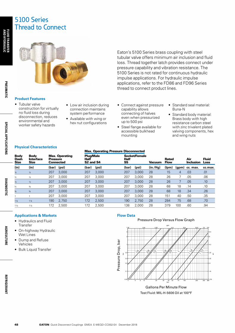
48
FLUID
TRAN
SFERA
ND
HYD
RAU
LICPN
EUM
ATICSPECIA
L APPLICATIO
NS
DIA
GN
OSTIC
AG
RICULTU
REREFRIG
ERAN
T
EATON Quick Disconnect Couplings EMEA E-MEQD-CC002-E4 December 2018
5100 Series Thread to Connect
Eaton’s 5100 Series brass coupling with steel tubular valve offers minimum air inclusion and fluid loss. Thread together latch provides connect under pressure capability and vibration resistance. The 5100 Series is not rated for continuous hydraulic impulse applications. For hydraulic impulse applications, refer to the FD86 and FD96 Series thread to connect product lines.
Product Features• Tubular valve
construction for virtually no fluid loss during disconnection, reduces environmental and worker safety hazards
Physical Characteristics Max. Operating Pressure DisconnectedBody Body Max. Operating Plug/Male Socket/Female Dash Interface Pressure Half Half Rated Air Fluid Size Size Connected S2 and S4 S5 Vacuum Flow Inclusion Loss
(in) (in) (bar) (psi) (bar) (psi) (bar) (psi) (in./Hg) (lpm) (gpm) cc. max. cc.max.
¼ ¼ 207 3,000 207 3,000 207 3,000 28 15 4 .03 .01 ½ 207 3,000 207 3,000 207 3,000 28 26 7 .05 .06
½ ½ 207 3,000 207 3,000 207 3,000 28 26 7 .05 .10 ¾ 207 3,000 207 3,000 207 3,000 28 68 18 .14 .10
¾ ¾ 207 3,000 207 3,000 207 3,000 28 68 18 .34 .261 1 207 3,000 207 3,000 207 3,000 28 151 40 .50 .351¼ 1¼ 190 2,750 172 2,500 190 2,750 28 284 75 .68 .701½ 1½ 172 2,500 172 2,500 138 2,000 28 379 100 .60 .94
• Low air inclusion during connection maintains system performance
• Available with wing or hex nut configurations
• Connect against pressure capability allows connecting of halves even when pressurized up to 500 psi
• Steel flange available for accessible bulkhead mounting
Applications & Markets• Hydraulics and Fluid
Transfer• On-highway Hydraulic
Wet Lines• Dump and Refuse
Vehicles• Bulk Liquid Transfer
• Standard seal material: Buna-N
• Standard body material: Brass body with high resistance carbon steel with zinc trivalent plated valving components, hex and wing nuts
Flow DataPressure Drop Versus Flow Graph
Gallons Per Minute Flow
Test Fluid: MIL-H-5606 Oil at 100°F
Pre
ssu
re D
rop
, bar
4 6 8 10 20 30 40 50 70 100 200 300 3800.05
0.1
0.2
0.3
0.5
1
2
3
bar
lpm
1.06 2.64 5.28 13.2 26.4 52.8 79 100
0.725
1.45
2.9
4.35
7.25
14.5
29
43.5
gpm
psi1/4 1/
2
5/8 13/8
3/4 1 1/4
1 1/2

49
PNEU
MAT
ICSP
ECIA
L A
PPLI
CATI
ON
SD
IAG
NO
STIC
AG
RICU
LTU
RERE
FRIG
ERA
NT
FLU
ID T
RAN
SFER
AN
D H
YDRA
ULI
C
EATON Quick Disconnect Couplings EMEA E-MEQD-CC002-E4 December 2018
Dimensions (Female NPT, Valved without Flange)Part Number Coupling Body Port Dimensions Buna-N Type Size Size Thread Type Fig. A B Hex 1 Hex 2
mm (in) mm (in) mm (in) mm (in)
5100-S2-4B Plug/Male ¼ -27 Female NPT 1 47.8 (1.88) 22.9 (.90) 17.5 (.69) - -
5110-S5-4B Socket/Female ¼ -27 Female NPT 2 53.3 (2.10) 33.5 (1.32) 14.2 (.56) 30.2 (1.19)
5111-4B Complete ¼ ¼ -27 Female NPT 3 81.3 (3.20) - - - - - -
5100-S2-6B Plug/Male ¼ ¼-18 Female NPT 1 65.5 (2.58) 26.7 1.05) 23.9 (.94) - -
5110-S5-6B Socket/Female ¼ ¼-18 Female NPT 2 61.0 (2.40) 38.9 (1.53) 19.3 (.76) 35.1 (1.38)
5111-6B Complete ¼ ¼-18 Female NPT 3 104.4 (4.11) - - - - - -
5100-S2-8B Plug/Male ½ -18 Female NPT 1 65.5 (2.58) 26.7 (1.05) 23.9 (.94) - -
5110-S5-8B Socket/Female ½ -18 Female NPT 2 61.0 (2.40) 38.9 (1.53) 19.3 (.76) 35.1 (1.38)
5111-8B Complete ½ -18 Female NPT 3 104.4 (4.11) - - - - - -
5100-S2-10B Plug/Male ½ ½-14 Female NPT 1 79.0 (3.11) 35.1 (1.38) 30.2 (1.19) - -
5110-S5-10B Socket/Female ½ ½-14 Female NPT 2 78.0 (3.07) 50.3 (1.98) 29.5 (1.16) 44.5 (1.75)
5111-10B Complete ½ ½-14 Female NPT 3 132.3 (5.21) - - - - - -
5100-S2-12B Plug/Male ¾ ¾ ¾-14 Female NPT 1 79.0 (3.11) 35.1 (1.38) 30.2 (1.19) - -
5110-S5-12B Socket/Female ¾ ¾ ¾-14 Female NPT 2 78.0 (3.07) 50.3 (1.98) 29.5 (1.16) 44.5 (1.75)
5111-12B Complete ¾ ¾ ¾-14 Female NPT 3 132.3 (5.21) - - - - - -
5100-S2-16B Plug/Male 1 1 1-11½ Female NPT 1 90.2 (3.55) 44.2 (1.74) 39.6 (1.56)
5110-S5-16B Socket/Female 1 1 1-11½ Female NPT 2 93.5 (3.68) 61.2 (2.41) 36.6 (1.44) 53.8 (2.12)
5111-16B Complete 1 1 1-11½ Female NPT 3 151.9 (5.98) - - - - - -
5100-S2-20B Plug/Male 1¼ 1¼ 1¼ - 11½ Female NPT 1 94.2 (3.71) 52.8 (2.08) 47.8 (1.88) - -
5110-S5-20B Socket/Female 1¼ 1¼ 1¼ - 11½ Female NPT 2 101.6 (4.00) 58.7 (2.31) 45.2 (1.78) 63.5 (2.50)
5111-20B Complete 1¼ 1¼ 1¼ - 11½ Female NPT 3 160.3 (6.31) - - - - - -
5100-S2-24B Plug/Male 1½ 1½ 1½ - 11½ Female NPT 1 104.6 (4.12) 62.5 (2.46) 55.6 (2.19) 55.6 (2.19)
5110-S5-24B Socket/Female 1½ 1½ 1½ - 11½ Female NPT 2 104.1 (4.10) 78.7 (3.1o) 50.8 (2.00) - -
5111-24B Complete 1½ 1½ 1½ - 11½ Female NPT 3 165.6 (6.52) - - - - - -
Figure 2Figure 1 Figure 3
5100 Series Thread to Connect
50
FLUID
TRAN
SFERA
ND
HYD
RAU
LICPN
EUM
ATICSPECIA
L APPLICATIO
NS
DIA
GN
OSTIC
AG
RICULTU
REREFRIG
ERAN
T
EATON Quick Disconnect Couplings EMEA E-MEQD-CC002-E4 December 2018
Dimensions (Female NPT, Valved WITH Flange)Part Number Coupling Body Port Dimensions Buna-N Type Size Size Thread Type Fig. A B Hex 1
mm (in) mm (in) mm (in)
5100-S4-4B Plug/Male ¼ -27 Female NPT 4 47.8 (1.88) 22.4 (.88) 23.3 (.96)5110-4B Complete ¼ -27 Female NPT 5 81.3 (3.20) - - - -5100-S4-6B Plug/Male ¼ ¼-18 Female NPT 4 65.5 (2.58) 26.7 (1.05) 28.5 (1.12)5110-6B Complete ¼ ¼-18 Female NPT 5 104.4 (4.11) - - - -5100-S4-8B Plug/Male ½ -18 Female NPT 4 65.5 (2.58) 26.7 (1.05) 28.5 (1.12)5110-8B Complete ½ -18 Female NPT 5 104.4 (4.11) - - - -5100-S4-10B Plug/Male ½ ½-14 Female NPT 4 79.0 (3.11) 35.2 (1.35) 41.2 (1.62)5110-10B Complete ½ ½-14 Female NPT 5 132.3 (5.21) - - - -5100-S4-12B Plug/Male ¾ ¾ ¾-14 Female NPT 4 79.0 (3.11) 35.2 (1.35) 41.2 (1.62)5110-12B Complete ¾ ¾ ¾-14 Female NPT 5 132.3 (5.21) - - - -5100-S4-16B Plug/Male 1 1 1-11½ Female NPT 4 90.2 (3.55) 44.2 (1.74) 47.8 (1.88)5100-S4-20B Plug/Male 1¼ 1¼ 1¼-11½ Female NPT 4 94.2 (3.71) 52.8 (2.08) 53.9 (2.12)5110-20B Complete 1¼ 1¼ 1¼-11½ Female NPT 5 160.3 (6.31) - - - -5100-S4-24B Plug/Male 1½ 1½ 1½-11½ Female NPT 4 104.6 (4.12) 62.5 (2.46) 63.5 (2.50)
5100 Series Thread to Connect
Figure 5Figure 4
Figure 6 Figure 7
Dimensions (Female NPT, Valved WITH Wing Nut Less Flange)Part Number Coupling Body Port Dimensions Buna-N Type Size Size Thread Type Fig. A B Hex 1
mm (in) mm (in) mm (in)
5100-S5-4B Socket/Female ¼ -27 Female NPT 6 53.3 (2.10) 77.0 (3.03) 14.2 (.56)5101-4B Complete ¼ -27 Female NPT 7 81.3 (3.20) - - - -5100-S5-6B Socket/Female ¼ ¼-18 Female NPT 6 61.0 (2.40) 87.4 (3.44) 19.3 (.76)5101-6B Complete ¼ ¼-18 Female NPT 7 104.4 (4.11) - - - -5100-S5-8B Socket/Female ½ -18 Female NPT 6 61.0 (2.40) 87.4 (3.44) 19.3 (.76)5101-8B Complete ½ -18 Female NPT 7 104.4 (4.11) - - - -5100-S5-10B Socket/Female ½ ½-14 Female NPT 6 78.0 (3.07) 104.9 (4.13) 29.5 (1.16)5101-10B Complete ½ ½-14 Female NPT 7 132.3 (5.21) - - - -5100-S5-12B Socket/Female ¾ ¾ ¾-14 Female NPT 6 78.0 (3.07) 104.9 (4.13) 29.5 (1.16)5101-12B Complete ¾ ¾ ¾-14 Female NPT 7 132.3 (5.21) - - - -5100-S5-16B Socket/Female 1 1 1-11½ Female NPT 6 93.5 (3.68) 111.3 (4.38) 36.6 (1.44)5101-16B Complete 1 1 1-11½ Female NPT 7 151.9 (5.98) - - - -5100-S5-20B Socket/Female 1¼ 1¼ 1¼-11½ Female Pipe 6 101.6 (4.00) 133.9 (5.27) 45.2 (1.78)5101-20B Complete 1¼ 1¼ 1¼-11½ Female NPT 7 160.3 (6.31) - - - -5100-S5-24B Socket/Female 1½ 1½ 1½-11½ Female NPT 6 104.1 (4.10) 136.7 (5.38) 50.8 (2.00) 5101-24B Complete 1½ 1½ 1½-11½ Female NPT 7 165.6 (6.52) - - - -
Note: Uses the 5100-S2 series plug/male half shown on page 49.

51
PNEU
MAT
ICSP
ECIA
L A
PPLI
CATI
ON
SD
IAG
NO
STIC
AG
RICU
LTU
RERE
FRIG
ERA
NT
FLU
ID T
RAN
SFER
AN
D H
YDRA
ULI
C
EATON Quick Disconnect Couplings EMEA E-MEQD-CC002-E4 December 2018
5100 Series Thread to Connect
Dimensions (Female NPT, Valved WITH Wing Nut and Flange)Part Number Coupling Body Port Dimensions Buna-N Type Size Size Thread Type Fig. A
mm (in)
5100-4B Complete ¼ -27 Female NPT 8 81.3 (3.24)5100-6B Complete ¼ ¼-18 Female NPT 8 104.4 (4.11)5100-8B Complete ½ -18 Female NPT 8 104.4 (4.11)5100-10B Complete ½ ½-14 Female NPT 8 132.3 (5.21)5100-12B Complete ¾ ¾ ¾-14 Female NPT 8 132.3 (5.21)5100-16B Complete 1 1 1-11½ Female NPT 8 151.9 (5.89)5100-20B Complete 1¼ 1¼ 1¼-11½ Female NPT 8 160.3 (6.33)5100-24B Complete 1½ 1½ 1½-11½ Female NPT 8 165.6 (6.54)
Note: Uses the 5100-S2 series plug/male half shown on page 49.
Repair KitsPart Number Body Buna-N Size
FF098-04 ¼
FF098-08 & ½FF098-12 & ¾FF098-16 1
FF098-20 1¼
FF098-24 1½
Note: Each kit will repair both plug/male and socket/female halves.
Dust Caps and Dust PlugsPart Number Body Dust Cap with Chain Dust Plug with Chain Size
5100-S7-5 5100-S9-5 ¼
5100-S7-8 5100-S9-8 & ½5100-S7-12 5100-S9-12 & ¾5100-S7-16 5100-S9-16 1
5100-S7-20 5100-S9-20 1¼
5100-S7-24 5100-S9-24 1½
6-Bolt Flange AssemblyPart Number Body Dimensions 6-Bolt Flange Assembly Size A B
mm (in) mm (in)
150-22-5 ¼ 5.11 (.201) 33.6 (1.44)150-22-8 & ½ 5.11 (.201) 42.9 (1.69)150-22-12 & ¾ 5.11 (.201) 53.8 (2.12)150-22-16 1 5.11 (.201) 60.5 (2.38)150-22-20 1¼ 5.11 (.201) 66.5 (2.62)5100-22-245 1½ 5.11 (.201) 82.6 (3.25)
*To order caps and plugs without chain, order cap by part number 5100-32-(size) and plug by part number 5100-41-(size).
**6 Bolt Flange-holes equally spaced. (See “A” for bolt hole diameter, and “B” for bolt circle diameter).
Dust Capwith Chain*
Dust Plugwith Chain*
6 Bolt Flange**Assembly
Figure 8
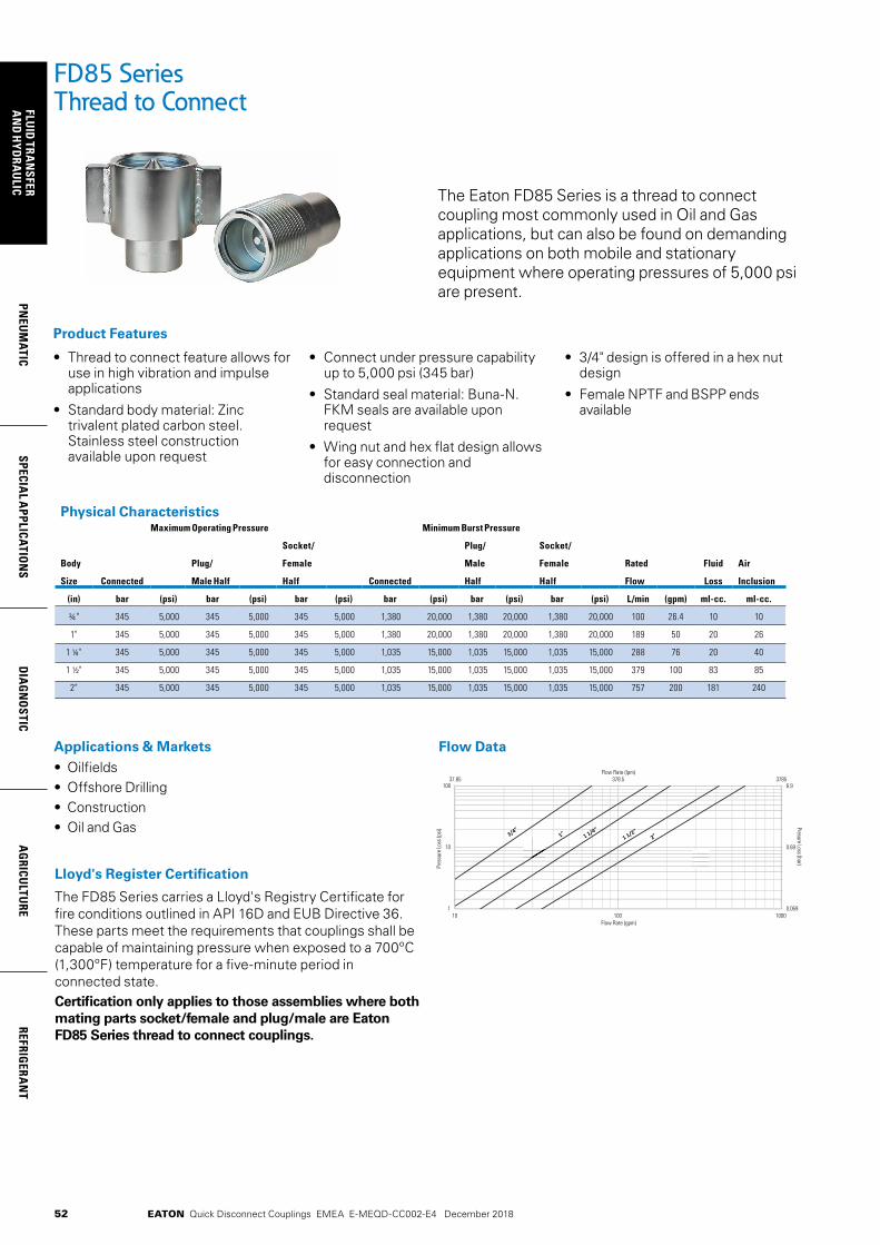
52
FLUID
TRAN
SFERA
ND
HYD
RAU
LICPN
EUM
ATICSPECIA
L APPLICATIO
NS
DIA
GN
OSTIC
AG
RICULTU
REREFRIG
ERAN
T
EATON Quick Disconnect Couplings EMEA E-MEQD-CC002-E4 December 2018
FD85 Series Thread to Connect
The Eaton FD85 Series is a thread to connect coupling most commonly used in Oil and Gas applications, but can also be found on demanding applications on both mobile and stationary equipment where operating pressures of 5,000 psi are present.
• Thread to connect feature allows for use in high vibration and impulse applications
• Standard body material: Zinc trivalent plated carbon steel. Stainless steel construction available upon request
• Connect under pressure capability up to 5,000 psi (345 bar)
• Standard seal material: Buna-N. FKM seals are available upon request
• Wing nut and hex flat design allows for easy connection and disconnection
• 3/4" design is offered in a hex nut design
• Female NPTF and BSPP ends available
Product Features
Applications & Markets• Oilfields• Offshore Drilling• Construction• Oil and Gas
Flow Data
Lloyd's Register Certification
The FD85 Series carries a Lloyd's Registry Certificate for fire conditions outlined in API 16D and EUB Directive 36. These parts meet the requirements that couplings shall be capable of maintaining pressure when exposed to a 700ºC (1,300ºF) temperature for a five-minute period in connected state.Certification only applies to those assemblies where both mating parts socket/female and plug/male are Eaton FD85 Series thread to connect couplings.
Physical CharacteristicsMaximum Operating Pressure Minimum Burst Pressure
Body
Size Connected
Plug/
Male Half
Socket/
Female
Half Connected
Plug/
Male
Half
Socket/
Female
Half
Rated
Flow
Fluid
Loss
Air
Inclusion
(in) bar (psi) bar (psi) bar (psi) bar (psi) bar (psi) bar (psi) L/min (gpm) ml-cc. ml-cc.
¾" 345 5,000
345 5,000
345
5,000 1,380 20,000
1,380 20,000 1,380
20,000 100 26.4 10 10
1" 345 5,000
345
5,000
345 5,000
1,380
20,000
1,380 20,000
1,380
20,000
189 50 20 26
1 ¼" 345 5,000 345
5,000
345
5,000
1,035
15,000
1,035
15,000
1,035
15,000 288 76 20 40
1 ½" 345 5,000 345
5,000
345
5,000
1,035
15,000
1,035
15,000
1,035
15,000
379 100 83 85
2" 345 5,000 345 5,000
345 5,000
1,035
15,000
1,035
15,000
1,035
15,000
757 200 181 240
37.85 378.5 3785
0.069
0.69
6.9
1
10
100
10 100 1000
Flow Rate (lpm)
Presure Loss (bar) Pr
essu
re Lo
ss (p
si)
Flow Rate (gpm)
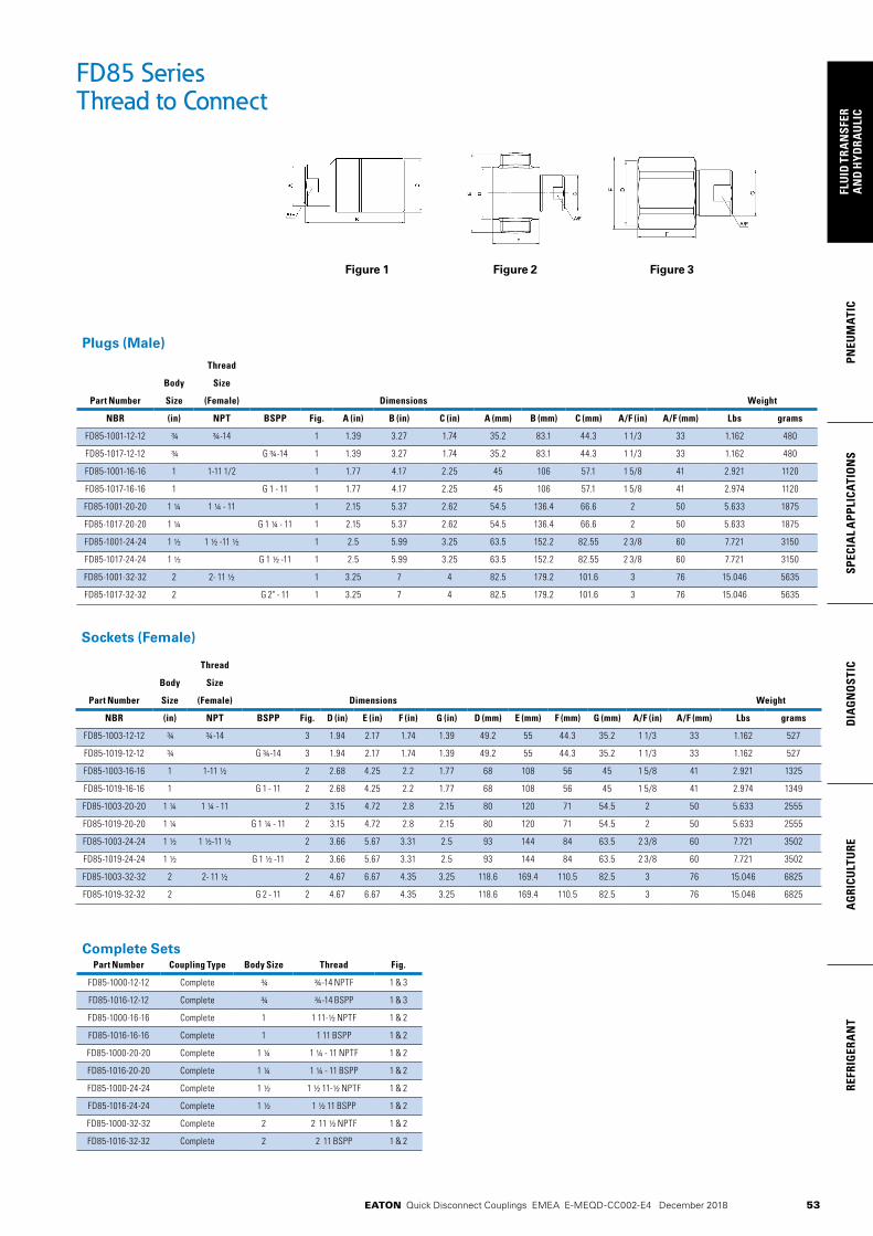
53
PNEU
MAT
ICSP
ECIA
L A
PPLI
CATI
ON
SD
IAG
NO
STIC
AG
RICU
LTU
RERE
FRIG
ERA
NT
FLU
ID T
RAN
SFER
AN
D H
YDRA
ULI
C
EATON Quick Disconnect Couplings EMEA E-MEQD-CC002-E4 December 2018
FD85 Series Thread to Connect
Plugs (Male)
Part Number
Body
Size
Thread
Size
(Female) Dimensions Weight
NBR (in) NPT BSPP Fig. A (in) B (in) C (in) A (mm) B (mm) C (mm) A/F (in) A/F (mm) Lbs grams
FD85-1001-12-12 ¾ ¾-14 1 1.39 3.27 1.74 35.2 83.1 44.3 1 1/3 33 1.162 480
FD85-1017-12-12 ¾ G ¾-14 1 1.39 3.27 1.74 35.2 83.1 44.3 1 1/3 33 1.162 480
FD85-1001-16-16 1 1-11 1/2 1 1.77 4.17 2.25 45 106 57.1 1 5/8 41 2.921 1120
FD85-1017-16-16 1 G 1 - 11 1 1.77 4.17 2.25 45 106 57.1 1 5/8 41 2.974 1120
FD85-1001-20-20 1 ¼ 1 ¼ - 11 1 2.15 5.37 2.62 54.5 136.4 66.6 2 50 5.633 1875
FD85-1017-20-20 1 ¼ G 1 ¼ - 11 1 2.15 5.37 2.62 54.5 136.4 66.6 2 50 5.633 1875
FD85-1001-24-24 1 ½ 1 ½ -11 ½ 1 2.5 5.99 3.25 63.5 152.2 82.55 2 3/8 60 7.721 3150
FD85-1017-24-24 1 ½ G 1 ½ -11 1 2.5 5.99 3.25 63.5 152.2 82.55 2 3/8 60 7.721 3150
FD85-1001-32-32 2 2- 11 ½ 1 3.25 7 4 82.5 179.2 101.6 3 76 15.046 5635
FD85-1017-32-32 2 G 2" - 11 1 3.25 7 4 82.5 179.2 101.6 3 76 15.046 5635
Sockets (Female)
Part Number
Body
Size
Thread
Size
(Female) Dimensions Weight
NBR (in) NPT BSPP Fig. D (in) E (in) F (in) G (in) D (mm) E (mm) F (mm) G (mm) A/F (in) A/F (mm) Lbs grams
FD85-1003-12-12 ¾ ¾-14 3 1.94 2.17 1.74 1.39 49.2 55 44.3 35.2 1 1/3 33 1.162 527
FD85-1019-12-12 ¾ G ¾-14 3 1.94 2.17 1.74 1.39 49.2 55 44.3 35.2 1 1/3 33 1.162 527
FD85-1003-16-16 1 1-11 ½ 2 2.68 4.25 2.2 1.77 68 108 56 45 1 5/8 41 2.921 1325
FD85-1019-16-16 1 G 1 - 11 2 2.68 4.25 2.2 1.77 68 108 56 45 1 5/8 41 2.974 1349
FD85-1003-20-20 1 ¼ 1 ¼ - 11 2 3.15 4.72 2.8 2.15 80 120 71 54.5 2 50 5.633 2555
FD85-1019-20-20 1 ¼ G 1 ¼ - 11 2 3.15 4.72 2.8 2.15 80 120 71 54.5 2 50 5.633 2555
FD85-1003-24-24 1 ½ 1 ½-11 ½ 2 3.66 5.67 3.31 2.5 93 144 84 63.5 2 3/8 60 7.721 3502
FD85-1019-24-24 1 ½ G 1 ½ -11 2 3.66 5.67 3.31 2.5 93 144 84 63.5 2 3/8 60 7.721 3502
FD85-1003-32-32 2 2- 11 ½ 2 4.67 6.67 4.35 3.25 118.6 169.4 110.5 82.5 3 76 15.046 6825
FD85-1019-32-32 2 G 2 - 11 2 4.67 6.67 4.35 3.25 118.6 169.4 110.5 82.5 3 76 15.046 6825
Complete SetsPart Number Coupling Type Body Size Thread Fig.
FD85-1000-12-12 Complete ¾ ¾-14 NPTF 1 & 3
FD85-1016-12-12 Complete ¾ ¾-14 BSPP 1 & 3
FD85-1000-16-16 Complete 1 1 11-½ NPTF 1 & 2
FD85-1016-16-16 Complete 1 1 11 BSPP 1 & 2
FD85-1000-20-20 Complete 1 ¼ 1 ¼ - 11 NPTF 1 & 2
FD85-1016-20-20 Complete 1 ¼ 1 ¼ - 11 BSPP 1 & 2
FD85-1000-24-24 Complete 1 ½ 1 ½ 11-½ NPTF 1 & 2
FD85-1016-24-24 Complete 1 ½ 1 ½ 11 BSPP 1 & 2
FD85-1000-32-32 Complete 2 2 11 ½ NPTF 1 & 2
FD85-1016-32-32 Complete 2 2 11 BSPP 1 & 2
Figure 1 Figure 2 Figure 3
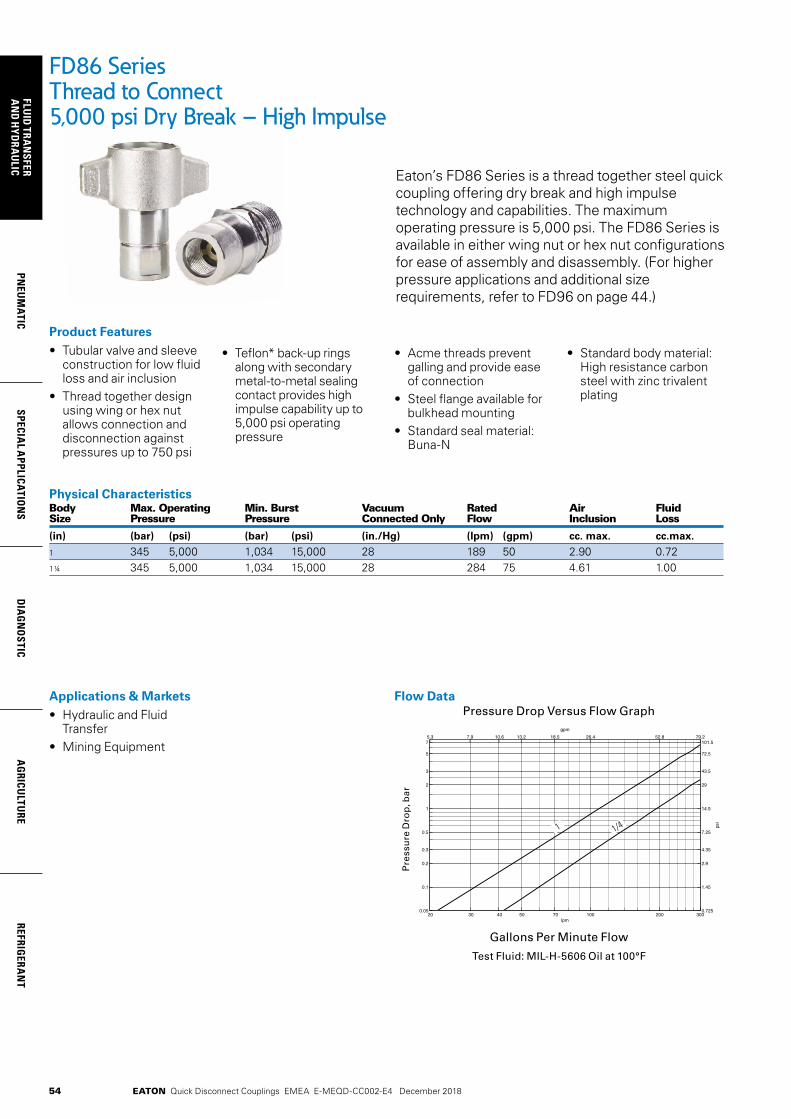
54
FLUID
TRAN
SFERA
ND
HYD
RAU
LICPN
EUM
ATICSPECIA
L APPLICATIO
NS
DIA
GN
OSTIC
AG
RICULTU
REREFRIG
ERAN
T
EATON Quick Disconnect Couplings EMEA E-MEQD-CC002-E4 December 2018
Flow DataPressure Drop Versus Flow Graph
Gallons Per Minute Flow
Test Fluid: MIL-H-5606 Oil at 100°F
20 30 40 50 70 100 200 3000.05
0.1
0.2
0.3
0.5
1
2
3
5
7
bar
lpm
5.3 7.9 10.6 13.2 18.5 26.4 52.8 79.2
0.725
1.45
2.9
4.35
7.25
14.5
29
43.5
72.5
101.5
gpm
psi
FD86 Series Thread to Connect 5,000 psi Dry Break – High Impulse
Eaton’s FD86 Series is a thread together steel quick coupling offering dry break and high impulse technology and capabilities. The maximum operating pressure is 5,000 psi. The FD86 Series is available in either wing nut or hex nut configurations for ease of assembly and disassembly. (For higher pressure applications and additional size requirements, refer to FD96 on page 44.)
Product Features• Tubular valve and sleeve
construction for low fluid loss and air inclusion
• Thread together design using wing or hex nut allows connection and disconnection against pressures up to 750 psi
• Teflon* back-up rings along with secondary metal-to-metal sealing contact provides high impulse capability up to 5,000 psi operating pressure
• Acme threads prevent galling and provide ease of connection
• Steel flange available for bulkhead mounting
• Standard seal material: Buna-N
• Standard body material: High resistance carbon steel with zinc trivalent plating
Physical Characteristics Body Max. Operating Min. Burst Vacuum Rated Air Fluid Size Pressure Pressure Connected Only Flow Inclusion Loss
(in) (bar) (psi) (bar) (psi) (in./Hg) (lpm) (gpm) cc. max. cc.max.
1 345 5,000 1,034 15,000 28 189 50 2.90 0.721¼ 345 5,000 1,034 15,000 28 284 75 4.61 1.00
Applications & Markets• Hydraulic and Fluid
Transfer• Mining Equipment
1 1/4
Pre
ssu
re D
rop
, bar

55
PNEU
MAT
ICSP
ECIA
L A
PPLI
CATI
ON
SD
IAG
NO
STIC
AG
RICU
LTU
RERE
FRIG
ERA
NT
FLU
ID T
RAN
SFER
AN
D H
YDRA
ULI
C
EATON Quick Disconnect Couplings EMEA E-MEQD-CC002-E4 December 2018
Figure 2 Figure 3Figure 1
Dimensions (Female SAE O-Ring)Part Number Body Port Dimensions Buna-N FKM EPDM Type Size Size Thread Type Fig. A B Hex 1
mm (in) mm (in) mm (in)
FD86-1008-16-16 FD86-1043-16-16 FD86-1053-16-16 Plug/Male 1 15/16 15/16 - 12 Female SAE O-Ring 1 102.4 (4.03) 53.6 (2.11) 44.5 (1.75)
FD86-1010-16-16 FD86-1044-16-16 FD86-1054-16-16 Socket/Female 1 15/16 15/16 - 12 Female SAE O-Ring 2 117.3 (4.62) 114.3 (4.50) - -
FD86-1006-16-16 FD86-1042-16-16 FD86-1052-16-16 Socket/Female 1 15/16 15/16 - 12 Female SAE O-Ring 3 117.3 (4.62) 71.4 (2.81) 15.8 (1.62)
FD86-1008-20-20 FD86-1043-20-20 FD86-1053-20-20 Plug/Male 1¼ 1 1 - 12 Female SAE O-Ring 1 105.7 (4.16) 63.0 (2.48) 57.2 (2.25)
FD86-1010-20-20 FD86-1044-20-20 FD86-1054-20-20 Socket/Female 1¼ 1 1 - 12 Female SAE O-Ring 2 132.6 (5.22) 133.4 (5.25) - -
FD86-1006-20-20 FD86-1042-20-20 FD86-1052-20-20 Socket/Female 1¼ 1 1 - 12 Female SAE O-Ring 3 132.6 (5.22) 86.4 (3.40) 50.8 (2.00)
Dimensions (Female NPT)Part Number Body Port Dimensions Buna-N FKM EPDM Type Size Size Thread Type Fig. A B Hex 1
mm (in) mm (in) mm (in)
FD86-1002-16-16 FD86-1040-16-16 FD86-1050-16-16 Plug/Male 1 1 - 11 ½ 1 - 11 ½ Female NPT 1 111.8 (4.40) 53.6 (2.11) 44.5 (1.75)
FD86-1001-16-16 FD86-1039-16-16 FD86-1049-16-16 Socket/Female 1 1 - 11½ 1 - 11 ½ Female NPT 2 126.5 (4.98) 114.3 (4.50) - -
FD86-1004-16-16 FD86-1041-16-16 FD86-1051-16-16 Socket/Female 1 1 - 11½ 1- 11½ Female NPT 3 126.5 (4.98) 71.4 (2.81) 15.8 (1.62)
FD86-1002-20-20 FD86-1040-20-20 FD86-1050-20-20 Plug/Male 1¼ 1¼ - 11½ 1¼ - 11 ½ Female NPT 1 112.5 (4.43) 63.0 (2.48) 57.2 (2.25)
FD86-1001-20-20 FD86-1039-20-20 FD86-1049-20-20 Socket/Female 1¼ 1¼ - 11½ 1¼ - 11 ½ Female NPT 2 142.8 (5.62) 133.4 (5.25) - -
FD86-1004-20-20 FD86-1041-20-20 FD86-1051-20-20 Socket/Female 1¼ 1¼ - 11½ 1¼ - 11 ½ Female NPT 3 142.8 (5.62) 86.4 (3.40) 50.8 (2.00)
Repair KitsPart Number Body Coupling Buna-N FKM EPDM Size Type
FF10596-16 FF10597-16 FF10598-16 1 MaleFF10593-16 FF10594-16 FF10595-16 1 FemaleFF10596-20 FF10597-20 FF10598-20 1¼ MaleFF10593-20 FF10594-20 FF10595-20 1¼ Female
Dust Caps and Dust PlugsPart Number Body Dust Cap with Chain Dust Plug with Chain Size
FD86-1018-16 FD86-1016-16 1
FD86-1018-20 FD86-1016-20 1¼
Dust Plugwith Chain
Dust Capwith Chain
FD86 Series Thread to Connect 5,000 psi Dry Break – High Impulse
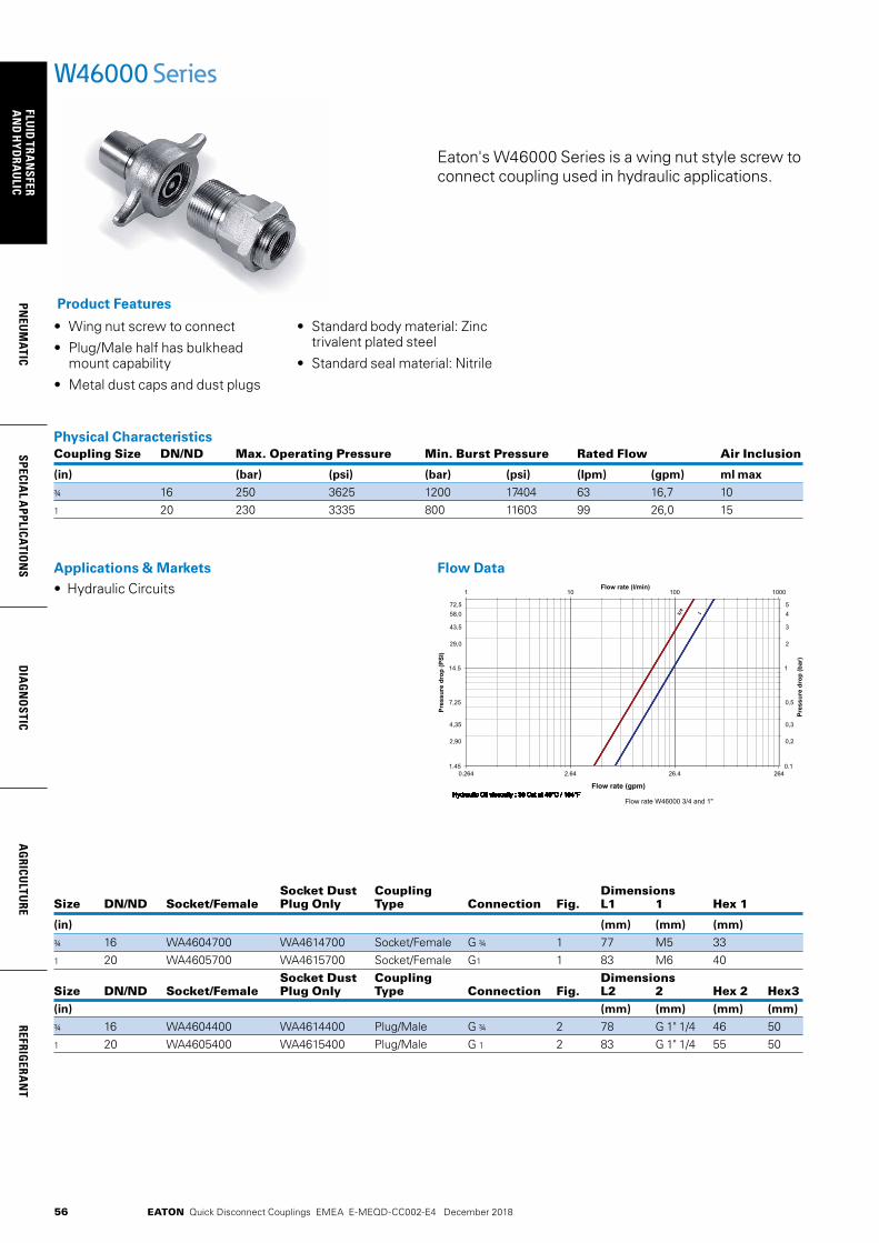
56
FLUID
TRAN
SFERA
ND
HYD
RAU
LICPN
EUM
ATICSPECIA
L APPLICATIO
NS
DIA
GN
OSTIC
AG
RICULTU
REREFRIG
ERAN
T
EATON Quick Disconnect Couplings EMEA E-MEQD-CC002-E4 December 2018
Eaton's W46000 Series is a wing nut style screw to connect coupling used in hydraulic applications.
• Wing nut screw to connect
• Plug/Male half has bulkhead mount capability
• Metal dust caps and dust plugs
• Standard body material: Zinc trivalent plated steel
• Standard seal material: Nitrile
Product Features
Physical Characteristics Coupling Size DN/ND Max. Operating Pressure Min. Burst Pressure Rated Flow Air Inclusion
(in) (bar) (psi) (bar) (psi) (lpm) (gpm) ml max
¾ 16 250 3625 1200 17404 63 16,7 101 20 230 3335 800 11603 99 26,0 15
W46000 Series
Socket Dust Coupling Dimensions Size DN/ND Socket/Female Plug Only Type Connection Fig. L1 1 Hex 1
(in) (mm) (mm) (mm)
¾ 16 WA4604700 WA4614700 Socket/Female G ¾ 1 77 M5 33 1 20 WA4605700 WA4615700 Socket/Female G1 1 83 M6 40 Socket Dust Coupling Dimensions Size DN/ND Socket/Female Plug Only Type Connection Fig. L2 2 Hex 2 Hex3(in) (mm) (mm) (mm) (mm) ¾ 16 WA4604400 WA4614400 Plug/Male G ¾ 2 78 G 1" 1/4 46 501 20 WA4605400 WA4615400 Plug/Male G 1 2 83 G 1" 1/4 55 50
Applications & Markets• Hydraulic Circuits
Flow Data
0.264 2.64 26.4 264 1.45
14.5
0.1
1
1 10 100 1000
Flow rate (gpm)
Pre
ssu
re d
rop
(P
SI)
Pre
ssu
re d
rop
(b
ar)
Flow rate (l/min)
Flow rate W46000 3/4 and 1" Hydraulic Oil viscosity : 30 Cst at 40°C / 104°F Hydraulic Oil viscosity : 30 Cst at 40°C / 104°F Hydraulic Oil viscosity : 30 Cst at 40°C / 104°F Hydraulic Oil viscosity : 30 Cst at 40°C / 104°F Hydraulic Oil viscosity : 30 Cst at 40°C / 104°F Hydraulic Oil viscosity : 30 Cst at 40°C / 104°F Hydraulic Oil viscosity : 30 Cst at 40°C / 104°F Hydraulic Oil viscosity : 30 Cst at 40°C / 104°F Hydraulic Oil viscosity : 30 Cst at 40°C / 104°F Hydraulic Oil viscosity : 30 Cst at 40°C / 104°F Hydraulic Oil viscosity : 30 Cst at 40°C / 104°F Hydraulic Oil viscosity : 30 Cst at 40°C / 104°F Hydraulic Oil viscosity : 30 Cst at 40°C / 104°F Hydraulic Oil viscosity : 30 Cst at 40°C / 104°F Hydraulic Oil viscosity : 30 Cst at 40°C / 104°F Hydraulic Oil viscosity : 30 Cst at 40°C / 104°F Hydraulic Oil viscosity : 30 Cst at 40°C / 104°F Hydraulic Oil viscosity : 30 Cst at 40°C / 104°F Hydraulic Oil viscosity : 30 Cst at 40°C / 104°F Hydraulic Oil viscosity : 30 Cst at 40°C / 104°F Hydraulic Oil viscosity : 30 Cst at 40°C / 104°F Hydraulic Oil viscosity : 30 Cst at 40°C / 104°F Hydraulic Oil viscosity : 30 Cst at 40°C / 104°F Hydraulic Oil viscosity : 30 Cst at 40°C / 104°F Hydraulic Oil viscosity : 30 Cst at 40°C / 104°F Hydraulic Oil viscosity : 30 Cst at 40°C / 104°F Hydraulic Oil viscosity : 30 Cst at 40°C / 104°F Hydraulic Oil viscosity : 30 Cst at 40°C / 104°F
72,5
58,0
43,5
29,0
2,90
4,35
7,25
5
4
3
2
0,2
0,3
0,5 13/4

57
PNEU
MAT
ICSP
ECIA
L A
PPLI
CATI
ON
SD
IAG
NO
STIC
AG
RICU
LTU
RERE
FRIG
ERA
NT
FLU
ID T
RAN
SFER
AN
D H
YDRA
ULI
C
EATON Quick Disconnect Couplings EMEA E-MEQD-CC002-E4 December 2018
• Designed and manufactured in accordance with Article 4.3 of the European Pressure Equipment Directive PED 2014/68/EU
• Proprietary profile
• Thread-to-connect with double shut-off valving
• Can be connected against 50 bar (725 psi) residual pressure
• Optional dust caps and plugs (PVC or aluminum)
• An alternative version can be offered with a safety feature which minimizes the risk of unscrewing in conditions of heavy vibration
• O-ring indication allows checking that connection is complete (thus guaranteeing full flow)
• Standard body material: Zinc trivalent plated steel
• Standard seal material: NBR
Product Features
Applications & Markets• Construction• Agriculture• Forestry Machinery• Snow-grooming
Machines
Seal Elastomer Data* Seal Elastomer Max. Operation Temperature Range
NBR (Nitrile) -20°C +100°C/-4°F +212°F
* For reference only, based on Eaton recommended temperatures.Contact Eaton technical support for further information on fluid compatibility.
W36000 SeriesThread-to-Connect
Eaton’s W36000 Series is a screw-to-connect quick disconnect coupling. Due to its design and the materials used, the W36000 Series quick disconnect coupling has excellent resistance to mechanical and hydraulic applications where vibration is present. The inner components of sizes ¾”, 1” & 1”¼ have a robust construction to withstand the harsh application needs. Additionally, the plug sleeve ensures protection of the sealing area upon disconnection.
Physical Characteristics
Body SizeNominal Flow Diameter Max. Operating Pressure
Max. Residual Pressure during Connection Rated Flow*
(in) (mm) bar (psi) bar (psi) L/min (gpm)
¼ 5.3 450 6525 50 725 12 3.17
7.3 450 6525 50 725 21 5.55
½ 10.2 400**250***
5800**3625*** 50 725 43 11.36
¾ 13.0 400 5800 50 725 77 20.34
1 16.9 300 4350 50 725 120 31.70
1¼ 22.4 300 4350 50 725 300 79.25
* Indicated values refer to a 1 bar / 14.5 psi pressure drop.** Operating pressures apply to BSPP and NPT threads.*** For ISO 8434-1 end connections.
0.264 2.64 26.4 0.1
1
0.5
0.3
0.2
54
3
1 10 100 1000
Flow rate (gpm)
Pres
sure
dro
p (P
SI)
Pres
sure
dro
p (b
ar)
Flow rate (l/min)
72.5
1.45
14.5
43.5
4.35
7.25
58
29
2.9
2
264
1/4
3/8
1/2
3/4
1" 1" 1
/4
Flow Data
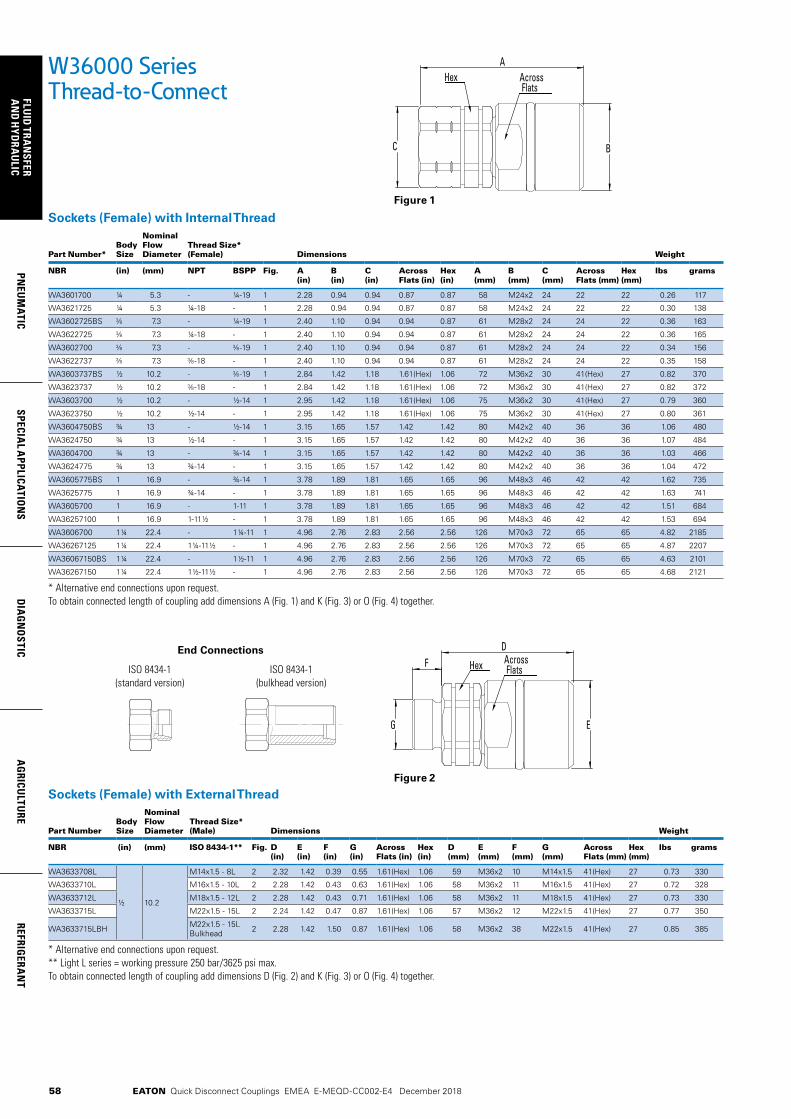
58
FLUID
TRAN
SFERA
ND
HYD
RAU
LICPN
EUM
ATICSPECIA
L APPLICATIO
NS
DIA
GN
OSTIC
AG
RICULTU
REREFRIG
ERAN
T
EATON Quick Disconnect Couplings EMEA E-MEQD-CC002-E4 December 2018
W36000 SeriesThread-to-Connect
Sockets (Female) with Internal Thread
Part Number*Body Size
Nominal Flow Diameter
Thread Size* (Female) Dimensions Weight
NBR (in) (mm) NPT BSPP Fig. A (in)
B (in)
C (in)
Across Flats (in)
Hex(in)
A (mm)
B (mm)
C (mm)
Across Flats (mm)
Hex (mm)
lbs grams
WA3601700 ¼ 5.3 - ¼-19 1 2.28 0.94 0.94 0.87 0.87 58 M24x2 24 22 22 0.26 117
WA3621725 ¼ 5.3 ¼-18 - 1 2.28 0.94 0.94 0.87 0.87 58 M24x2 24 22 22 0.30 138
WA3602725BS 7.3 - ¼-19 1 2.40 1.10 0.94 0.94 0.87 61 M28x2 24 24 22 0.36 163
WA3622725 7.3 ¼-18 - 1 2.40 1.10 0.94 0.94 0.87 61 M28x2 24 24 22 0.36 165
WA3602700 7.3 - -19 1 2.40 1.10 0.94 0.94 0.87 61 M28x2 24 24 22 0.34 156
WA3622737 7.3 -18 - 1 2.40 1.10 0.94 0.94 0.87 61 M28x2 24 24 22 0.35 158
WA3603737BS ½ 10.2 - -19 1 2.84 1.42 1.18 1.61(Hex) 1.06 72 M36x2 30 41(Hex) 27 0.82 370
WA3623737 ½ 10.2 -18 - 1 2.84 1.42 1.18 1.61(Hex) 1.06 72 M36x2 30 41(Hex) 27 0.82 372
WA3603700 ½ 10.2 - ½-14 1 2.95 1.42 1.18 1.61(Hex) 1.06 75 M36x2 30 41(Hex) 27 0.79 360
WA3623750 ½ 10.2 ½-14 - 1 2.95 1.42 1.18 1.61(Hex) 1.06 75 M36x2 30 41(Hex) 27 0.80 361
WA3604750BS ¾ 13 - ½-14 1 3.15 1.65 1.57 1.42 1.42 80 M42x2 40 36 36 1.06 480
WA3624750 ¾ 13 ½-14 - 1 3.15 1.65 1.57 1.42 1.42 80 M42x2 40 36 36 1.07 484
WA3604700 ¾ 13 - ¾-14 1 3.15 1.65 1.57 1.42 1.42 80 M42x2 40 36 36 1.03 466
WA3624775 ¾ 13 ¾-14 - 1 3.15 1.65 1.57 1.42 1.42 80 M42x2 40 36 36 1.04 472
WA3605775BS 1 16.9 - ¾-14 1 3.78 1.89 1.81 1.65 1.65 96 M48x3 46 42 42 1.62 735
WA3625775 1 16.9 ¾-14 - 1 3.78 1.89 1.81 1.65 1.65 96 M48x3 46 42 42 1.63 741
WA3605700 1 16.9 - 1-11 1 3.78 1.89 1.81 1.65 1.65 96 M48x3 46 42 42 1.51 684
WA36257100 1 16.9 1-11½ - 1 3.78 1.89 1.81 1.65 1.65 96 M48x3 46 42 42 1.53 694
WA3606700 1¼ 22.4 - 1¼-11 1 4.96 2.76 2.83 2.56 2.56 126 M70x3 72 65 65 4.82 2185
WA36267125 1¼ 22.4 1¼-11½ - 1 4.96 2.76 2.83 2.56 2.56 126 M70x3 72 65 65 4.87 2207
WA36067150BS 1¼ 22.4 - 1½-11 1 4.96 2.76 2.83 2.56 2.56 126 M70x3 72 65 65 4.63 2101
WA36267150 1¼ 22.4 1½-11½ - 1 4.96 2.76 2.83 2.56 2.56 126 M70x3 72 65 65 4.68 2121
* Alternative end connections upon request.To obtain connected length of coupling add dimensions A (Fig. 1) and K (Fig. 3) or O (Fig. 4) together.
Sockets (Female) with External Thread
Part NumberBody Size
Nominal Flow Diameter
Thread Size* (Male) Dimensions Weight
NBR (in) (mm) ISO 8434-1** Fig. D (in)
E (in)
F (in)
G (in)
Across Flats (in)
Hex(in)
D (mm)
E (mm)
F (mm)
G (mm)
Across Flats (mm)
Hex (mm)
lbs grams
WA3633708L
½ 10.2
M14x1.5 - 8L 2 2.32 1.42 0.39 0.55 1.61(Hex) 1.06 59 M36x2 10 M14x1.5 41(Hex) 27 0.73 330
WA3633710L M16x1.5 - 10L 2 2.28 1.42 0.43 0.63 1.61(Hex) 1.06 58 M36x2 11 M16x1.5 41(Hex) 27 0.72 328
WA3633712L M18x1.5 - 12L 2 2.28 1.42 0.43 0.71 1.61(Hex) 1.06 58 M36x2 11 M18x1.5 41(Hex) 27 0.73 330
WA3633715L M22x1.5 - 15L 2 2.24 1.42 0.47 0.87 1.61(Hex) 1.06 57 M36x2 12 M22x1.5 41(Hex) 27 0.77 350
WA3633715LBH M22x1.5 - 15L Bulkhead 2 2.28 1.42 1.50 0.87 1.61(Hex) 1.06 58 M36x2 38 M22x1.5 41(Hex) 27 0.85 385
* Alternative end connections upon request.** Light L series = working pressure 250 bar/3625 psi max.To obtain connected length of coupling add dimensions D (Fig. 2) and K (Fig. 3) or O (Fig. 4) together.
A
BC
Hex Across Flats
End Connections
ISO 8434-1(standard version)
ISO 8434-1(bulkhead version)
FD
G E
Hex Across Flats
Figure 1
Figure 2

59
PNEU
MAT
ICSP
ECIA
L A
PPLI
CATI
ON
SD
IAG
NO
STIC
AG
RICU
LTU
RERE
FRIG
ERA
NT
FLU
ID T
RAN
SFER
AN
D H
YDRA
ULI
C
EATON Quick Disconnect Couplings EMEA E-MEQD-CC002-E4 December 2018
W36000 SeriesThread-to-Connect
Plugs (Male) with Internal Thread
Part NumberBody Size
Nominal Flow Diameter
Thread Size* (Female) Dimensions Weight
NBR (in) (mm) NPT BSPP Fig. H (in)
I (in)
J (in)
K (in)
Hex 1 (in)
Hex 2(in)
H (mm)
I (mm)
J (mm)
K (mm)
Hex 1 (mm)
Hex 2 (mm)
lbs grams
WA3601400 ¼ 5.3 - ¼-19 3 2.17 1.26 0.94 1.22 1.14 0.87 55 32 24 31 29 22 0.41 184
WA3621425 ¼ 5.3 ¼-18 - 3 2.17 1.26 0.94 1.22 1.14 0.87 55 32 24 31 29 22 0.33 150
WA3602425BS 7.3 - ¼-19 3 2.28 1.38 0.94 1.26 1.26 0.87 58 35 24 32 32 22 0.36 164
WA3622425 7.3 ¼-18 - 3 2.28 1.38 0.94 1.26 1.26 0.87 58 35 24 32 32 22 0.37 166
WA3602400 7.3 - -19 3 2.28 1.38 0.94 1.26 1.26 0.87 58 35 24 32 32 22 0.35 158
WA3622437 7.3 -18 - 3 2.28 1.38 0.94 1.26 1.26 0.87 58 35 24 32 32 22 0.35 160
WA3603437BS ½ 10.2 - -19 3 2.52 1.77 1.18 1.46 1.61 1.06 64 45 30 37 41 27 0.61 276
WA3623437 ½ 10.2 -18 - 3 2.52 1.77 1.18 1.46 1.61 1.06 64 45 30 37 41 27 0.61 278
WA3603400 ½ 10.2 - ½-14 3 2.60 1.77 1.18 1.57 1.61 1.06 66 45 30 40 41 27 0.60 271
WA3623450 ½ 10.2 ½-14 - 3 2.60 1.77 1.18 1.57 1.61 1.06 66 45 30 40 41 27 0.60 273
WA3604450BS ¾ 13.0 - ½-14 3 3.03 1.97 1.57 1.85 1.81 1.42 77 50 40 47 46 36 1.01 456
WA3624450 ¾ 13.0 ½-14 - 3 3.03 1.97 1.57 1.85 1.81 1.42 77 50 40 47 46 36 1.01 460
WA3604400 ¾ 13.0 - ¾-14 3 3.03 1.97 1.57 1.85 1.81 1.42 77 50 40 47 46 36 0.97 442
WA3624475 ¾ 13.0 ¾-14 - 3 3.03 1.97 1.57 1.85 1.81 1.42 77 50 40 47 46 36 0.99 448
WA3605475BS 1 16.9 - ¾-14 3 3.62 2.36 1.81 2.24 2.17 1.65 92 60 46 57 55 42 1.77 805
WA3625475 1 16.9 ¾-14 - 3 3.62 2.36 1.81 2.24 2.17 1.65 92 60 46 57 55 42 1.79 811
WA3605400 1 16.9 - 1-11 3 3.62 2.36 1.81 2.24 2.17 1.65 92 60 46 57 55 42 1.66 751
WA36254100 1 16.9 1-11½ - 3 3.62 2.36 1.81 2.24 2.17 1.65 92 60 46 57 55 42 1.68 761
WA3606400 1¼ 22.4 - 1¼-11 3 4.72 3.50 2.83 2.76 3.03 2.56 120 89 72 70 77 65 5.56 2520
WA36264125 1¼ 22.4 1¼-11½ - 3 4.72 3.50 2.83 2.76 3.03 2.56 120 89 72 70 77 65 5.60 2542
WA36064150BS 1¼ 22.4 - 1½-11 3 4.72 3.50 2.83 2.76 3.03 2.56 120 89 72 70 77 65 5.37 2436
WA36264150 1¼ 22.4 1½-11½ - 3 4.72 3.50 2.83 2.76 3.03 2.56 120 89 72 70 77 65 5.41 2456
* Alternative end connections upon request.To obtain connected length of coupling add dimensions K (Fig. 3) and A (Fig. 1) or D (Fig. 2) together.
Plugs (Male) with External Thread
Part NumberBody Size
Nominal Flow Diameter
Thread Size* (Male) Dimensions Weight
NBR (in) (mm) ISO 8434-1**
Fig. L (in)
M (in)
N (in)
O (in)
P (in)
Hex 1 (in)
Hex 2(in)
L (mm)
M (mm)
N (mm)
O (mm)
P (mm)
Hex 1 (mm)
Hex 2 (mm)
lbs grams
WA3633408L
½ 10.2
M14x1.5 - 8L 4 1.93 1.77 0.39 1.42 0.55 1.61 1.06 49 45 10 36 M14x1.5 41 27 0.56 255
WA3633410L M16x1.5 - 10L 4 1.93 1.77 0.43 1.42 0.63 1.61 1.06 49 45 11 36 M16x1.5 41 27 0.56 253
WA3633412L M18x1.5 - 12L 4 1.93 1.77 0.43 1.42 0.71 1.61 1.06 49 45 11 36 M18x1.5 41 27 0.56 255
WA3633415L M22x1.5 - 15L 4 1.93 1.77 0.47 1.42 0.87 1.61 1.06 49 45 12 36 M22x1.5 41 27 0.61 275
WA3633415LBH M22x1.5 - 15LBulkhead 4 1.93 1.77 1.50 1.42 0.87 1.61 1.06 49 45 38 36 M22x1.5 41 27 0.68 310
* Alternative end connections upon request.** Light L series = working pressure 250 bar/3625 psi max.To obtain connected length of coupling add dimensions O (Fig. 4) and A (Fig. 1) or D (Fig. 2) together.
KH
I J
Hex 1 Hex 2
End Connections
ISO 8434-1(standard version)
ISO 8434-1(bulkhead version)
OL
N
M P
Hex 1 Hex 2
Figure 3
Figure 4

60
FLUID
TRAN
SFERA
ND
HYD
RAU
LICPN
EUM
ATICSPECIA
L APPLICATIO
NS
DIA
GN
OSTIC
AG
RICULTU
REREFRIG
ERAN
T
EATON Quick Disconnect Couplings EMEA E-MEQD-CC002-E4 December 2018
Metal Socket Dust Plug
PVC Socket Dust Plug
Metal Plug Dust Cap
PVC Plug Dust Cap
W36000 SeriesThread-to-Connect
Seal Kit for Servicing Sockets (Female)
Body SizeSeal & Back-up Ring Kit*Part Number NBR seals & PTFE back-up rings
(in)
¼ WG3601700 10 seals + 10 back-up rings
WG3602700 10 seals + 10 back-up rings
½ WG3603700 10 seals + 10 back-up rings
¾ WG3604700 5 seals + 5 back-up rings
1 WG3605700 5 seals + 5 back-up rings
1½ WG3606700 1 seal + 1 back-up ring
* The valve seal is not included in our repair kits
Dust Plugs and Dust CapsBody Size Socket Dust Plug Part Number Plug Dust Cap Part Number
(in) Anodized Aluminum
PVC Anodized Aluminum
PVC
¼ - WP3611700 - WP3611400
- WP3612700 - WP3612400
½ WD3613700 WP3613700 WD3613400 WP3613400
¾ - WP3614700 - WP3614400
1 - WP3615700 - WP3615400
1¼ - WP3616700 - WP3616400
For installation instructions, please contact your Eaton sales representative
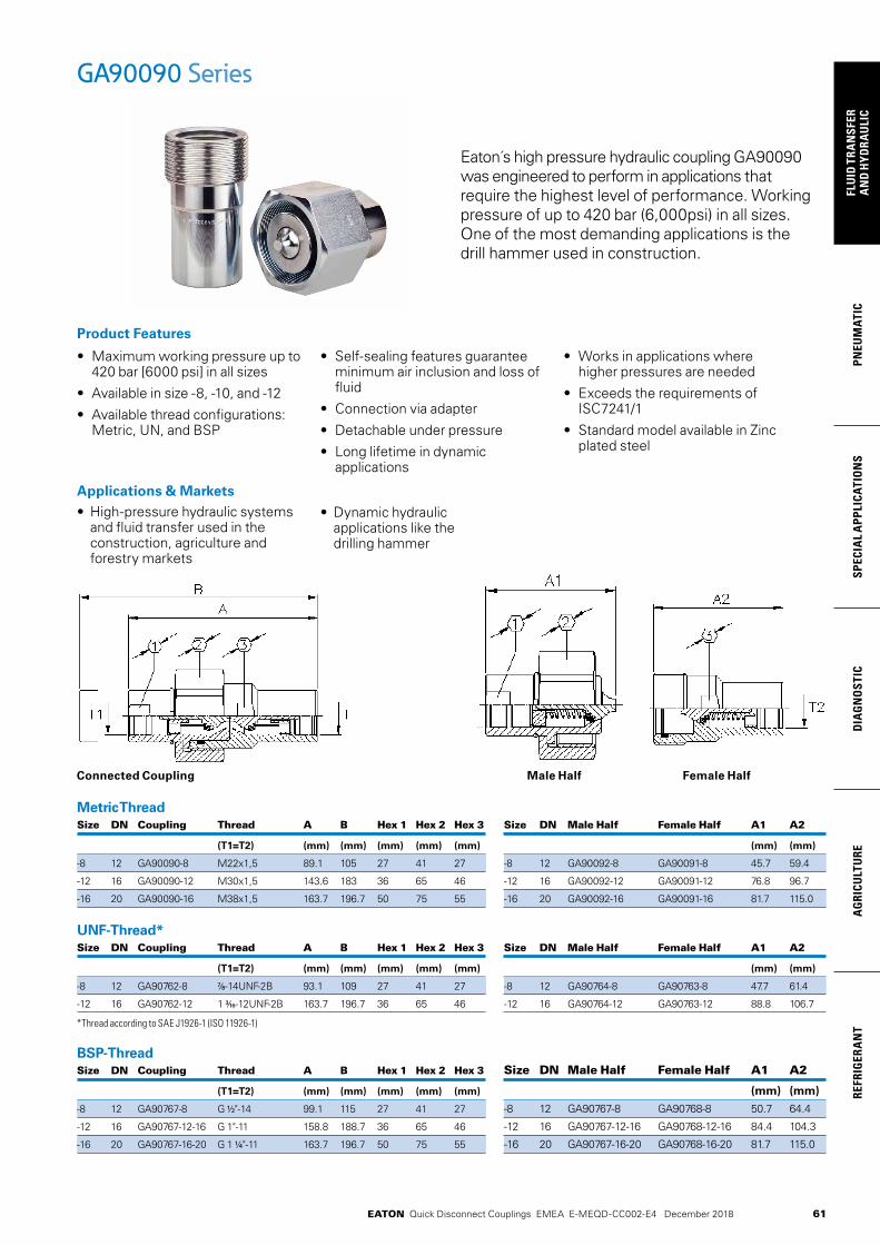
61
PNEU
MAT
ICSP
ECIA
L A
PPLI
CATI
ON
SD
IAG
NO
STIC
AG
RICU
LTU
RERE
FRIG
ERA
NT
FLU
ID T
RAN
SFER
AN
D H
YDRA
ULI
C
EATON Quick Disconnect Couplings EMEA E-MEQD-CC002-E4 December 2018
GA90090 Series
Applications & Markets• High-pressure hydraulic systems
and fluid transfer used in the construction, agriculture and forestry markets
Connected Coupling
Eaton´s high pressure hydraulic coupling GA90090 was engineered to perform in applications that require the highest level of performance. Working pressure of up to 420 bar (6,000psi) in all sizes. One of the most demanding applications is the drill hammer used in construction.
• Maximum working pressure up to 420 bar [6000 psi] in all sizes
• Available in size -8, -10, and -12
• Available thread configurations: Metric, UN, and BSP
• Self-sealing features guarantee minimum air inclusion and loss of fluid
• Connection via adapter
• Detachable under pressure
• Long lifetime in dynamic applications
• Works in applications where higher pressures are needed
• Exceeds the requirements of ISC7241/1
• Standard model available in Zinc plated steel
Product Features
• Dynamic hydraulic applications like the drilling hammer
Metric Thread Size DN Coupling Thread A B Hex 1 Hex 2 Hex 3
(T1=T2) (mm) (mm) (mm) (mm) (mm)
-8 12 GA90090-8 M22x1,5 89.1 105 27 41 27
-12 16 GA90090-12 M30x1,5 143.6 183 36 65 46
-16 20 GA90090-16 M38x1,5 163.7 196.7 50 75 55
UNF-Thread* Size DN Coupling Thread A B Hex 1 Hex 2 Hex 3
(T1=T2) (mm) (mm) (mm) (mm) (mm)
-8 12 GA90762-8 7/8-14UNF-2B 93.1 109 27 41 27
-12 16 GA90762-12 1 3/16-12UNF-2B 163.7 196.7 36 65 46
*Thread according to SAE J1926-1 (ISO 11926-1)
BSP-Thread Size DN Coupling Thread A B Hex 1 Hex 2 Hex 3
(T1=T2) (mm) (mm) (mm) (mm) (mm)
-8 12 GA90767-8 G 1/2"-14 99.1 115 27 41 27
-12 16 GA90767-12-16 G 1"-11 158.8 188.7 36 65 46
-16 20 GA90767-16-20 G 1 1/4"-11 163.7 196.7 50 75 55
Size DN Male Half Female Half A1 A2
(mm) (mm)
-8 12 GA90092-8 GA90091-8 45.7 59.4
-12 16 GA90092-12 GA90091-12 76.8 96.7
-16 20 GA90092-16 GA90091-16 81.7 115.0
Size DN Male Half Female Half A1 A2
(mm) (mm)
-8 12 GA90764-8 GA90763-8 47.7 61.4
-12 16 GA90764-12 GA90763-12 88.8 106.7
Size DN Male Half Female Half A1 A2
(mm) (mm)
-8 12 GA90767-8 GA90768-8 50.7 64.4
-12 16 GA90767-12-16 GA90768-12-16 84.4 104.3
-16 20 GA90767-16-20 GA90768-16-20 81.7 115.0
Male Half Female Half
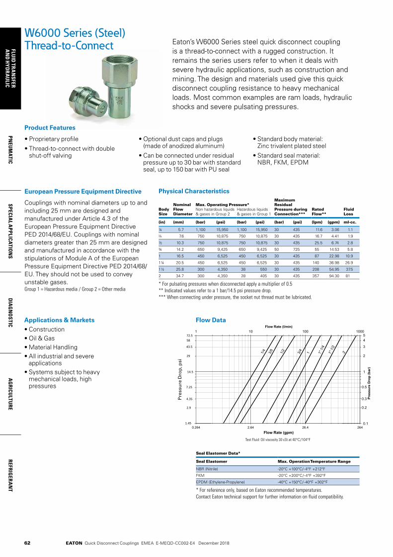
62
FLUID
TRAN
SFERA
ND
HYD
RAU
LICPN
EUM
ATICSPECIA
L APPLICATIO
NS
DIA
GN
OSTIC
AG
RICULTU
REREFRIG
ERAN
T
EATON Quick Disconnect Couplings EMEA E-MEQD-CC002-E4 December 2018
Physical Characteristics
Body Size
Nominal Flow Diameter
Max. Operating Pressure*Maximum Residual Pressure during Connection***
Non hazardous liquids & gases in Group 2
Hazardous liquids & gases in Group 1
Rated Flow**
Fluid Loss
(in) (mm) (bar) (psi) (bar) (psi) (bar) (psi) (lpm) (gpm) ml-cc.
¼ 5.7 1,100 15,950 1,100 15,950 30 435 11.6 3.06 1.1
7.6 750 10,875 750 10,875 30 435 16.7 4.41 1.9
½ 10.3 750 10,875 750 10,875 30 435 25.5 6.74 2.8
¾ 14.2 650 9,425 650 9,425 50 725 55 14.53 5.8
1 16.5 450 6,525 450 6,525 30 435 87 22.98 10.9
1¼ 20.5 450 6,525 450 6,525 30 435 140 36.98 26.9
1½ 25.8 300 4,350 38 550 30 435 208 54.95 37.5
2 34.7 300 4,350 28 405 30 435 357 94.30 81
* For pulsating pressures when disconnected apply a multiplier of 0.5** Indicated values refer to a 1 bar/14.5 psi pressure drop.*** When connecting under pressure, the socket nut thread must be lubricated.
• Proprietary profile
• Thread-to-connect with double shut-off valving
• Optional dust caps and plugs (made of anodized aluminum)
• Can be connected under residual pressure up to 30 bar with standard seal, up to 150 bar with PU seal
• Standard body material: Zinc trivalent plated steel
• Standard seal material: NBR, FKM, EPDM
Product Features
Eaton’s W6000 Series steel quick disconnect coupling is a thread-to-connect with a rugged construction. It remains the series users refer to when it deals with severe hydraulic applications, such as construction and mining. The design and materials used give this quick disconnect coupling resistance to heavy mechanical loads. Most common examples are ram loads, hydraulic shocks and severe pulsating pressures.
Seal Elastomer Data*
Seal Elastomer Max. Operation Temperature Range
NBR (Nitrile) -20°C +100°C/-4°F +212°F
FKM -20°C +200°C/-4°F +392°F
EPDM (Ethylene-Propylene) -40°C +150°C/-40°F +302°F
* For reference only, based on Eaton recommended temperatures.Contact Eaton technical support for further information on fluid compatibility.
Couplings with nominal diameters up to and including 25 mm are designed and manufactured under Article 4.3 of the European Pressure Equipment Directive PED 2014/68/EU. Couplings with nominal diameters greater than 25 mm are designed and manufactured in accordance with the stipulations of Module A of the European Pressure Equipment Directive PED 2014/68/EU. They should not be used to convey unstable gases.Group 1 = Hazardous media / Group 2 = Other media
European Pressure Equipment Directive
Applications & Markets• Construction• Oil & Gas• Material Handling• All industrial and severe
applications• Systems subject to heavy
mechanical loads, high pressures
0.264 2.64 26.4 0.1
1
0.5
0.3
0.2
54
3
1 10 100 1000
Flow Rate (gpm)
Pre
ssu
re d
rop
(P
SI)
Pre
ssu
re D
rop
(b
ar)
Flow Rate (l/min)
72.5
1.45
14.5
43.5
4.35
7.25
58
29
2.9
2
264
1/4
3/8
1/2
3/4
1" 1
/4
1" 1
/2
1 2
Test Fluid: Oil viscosity 30 cSt at 40°C/104°F
W6000 Series (Steel)Thread-to-Connect
Flow Data
Pre
ssu
re D
rop
, psi
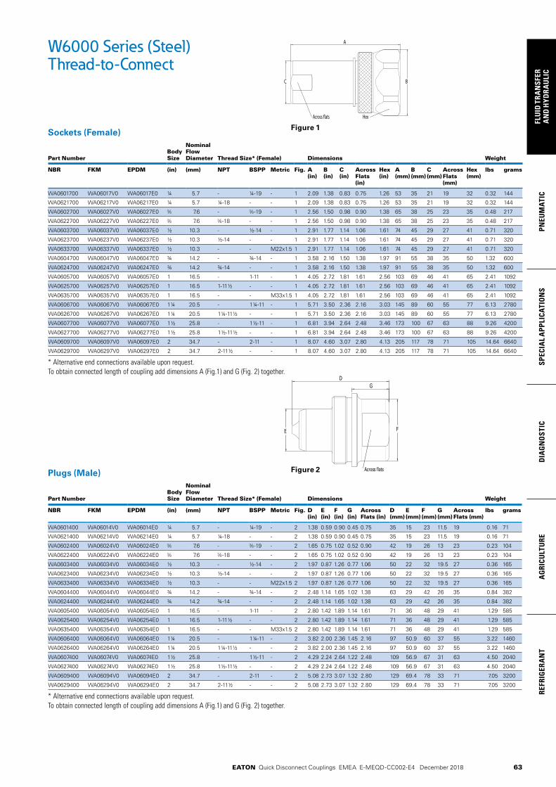
63
PNEU
MAT
ICSP
ECIA
L A
PPLI
CATI
ON
SD
IAG
NO
STIC
AG
RICU
LTU
RERE
FRIG
ERA
NT
FLU
ID T
RAN
SFER
AN
D H
YDRA
ULI
C
EATON Quick Disconnect Couplings EMEA E-MEQD-CC002-E4 December 2018
W6000 Series (Steel)Thread-to-Connect
Sockets (Female)
Part NumberBody Size
Nominal Flow Diameter Thread Size* (Female) Dimensions Weight
NBR FKM EPDM (in) (mm) NPT BSPP Metric Fig. A (in)
B (in)
C (in)
Across Flats (in)
Hex(in)
A (mm)
B (mm)
C (mm)
Across Flats (mm)
Hex (mm)
lbs grams
WA0601700 WA06017V0 WA06017E0 ¼ 5.7 - ¼-19 - 1 2.09 1.38 0.83 0.75 1.26 53 35 21 19 32 0.32 144
WA0621700 WA06217V0 WA06217E0 ¼ 5.7 ¼-18 - - 1 2.09 1.38 0.83 0.75 1.26 53 35 21 19 32 0.32 144
WA0602700 WA06027V0 WA06027E0 7.6 - -19 - 1 2.56 1.50 0.98 0.90 1.38 65 38 25 23 35 0.48 217
WA0622700 WA06227V0 WA06227E0 7.6 -18 - - 1 2.56 1.50 0.98 0.90 1.38 65 38 25 23 35 0.48 217
WA0603700 WA06037V0 WA06037E0 ½ 10.3 - ½-14 - 1 2.91 1.77 1.14 1.06 1.61 74 45 29 27 41 0.71 320
WA0623700 WA06237V0 WA06237E0 ½ 10.3 ½-14 - - 1 2.91 1.77 1.14 1.06 1.61 74 45 29 27 41 0.71 320
WA0633700 WA06337V0 WA06337E0 ½ 10.3 - - M22x1.5 1 2.91 1.77 1.14 1.06 1.61 74 45 29 27 41 0.71 320
WA0604700 WA06047V0 WA06047E0 ¾ 14.2 - ¾-14 - 1 3.58 2.16 1.50 1.38 1.97 91 55 38 35 50 1.32 600
WA0624700 WA06247V0 WA06247E0 ¾ 14.2 ¾-14 - - 1 3.58 2.16 1.50 1.38 1.97 91 55 38 35 50 1.32 600
WA0605700 WA06057V0 WA06057E0 1 16.5 - 1-11 - 1 4.05 2.72 1.81 1.61 2.56 103 69 46 41 65 2.41 1092
WA0625700 WA06257V0 WA06257E0 1 16.5 1-11½ - - 1 4.05 2.72 1.81 1.61 2.56 103 69 46 41 65 2.41 1092
WA0635700 WA06357V0 WA06357E0 1 16.5 - - M33x1.5 1 4.05 2.72 1.81 1.61 2.56 103 69 46 41 65 2.41 1092
WA0606700 WA06067V0 WA06067E0 1¼ 20.5 - 1¼-11 - 1 5.71 3.50 2.36 2.16 3.03 145 89 60 55 77 6.13 2780
WA0626700 WA06267V0 WA06267E0 1¼ 20.5 1¼-11½ - - 1 5.71 3.50 2.36 2.16 3.03 145 89 60 55 77 6.13 2780
WA0607700 WA06077V0 WA06077E0 1½ 25.8 - 1½-11 - 1 6.81 3.94 2.64 2.48 3.46 173 100 67 63 88 9.26 4200
WA0627700 WA06277V0 WA06277E0 1½ 25.8 1½-11½ - - 1 6.81 3.94 2.64 2.48 3.46 173 100 67 63 88 9.26 4200
WA0609700 WA06097V0 WA06097E0 2 34.7 - 2-11 - 1 8.07 4.60 3.07 2.80 4.13 205 117 78 71 105 14.64 6640
WA0629700 WA06297V0 WA06297E0 2 34.7 2-11½ - - 1 8.07 4.60 3.07 2.80 4.13 205 117 78 71 105 14.64 6640
* Alternative end connections available upon request.To obtain connected length of coupling add dimensions A (Fig.1) and G (Fig. 2) together.
Plugs (Male)
Part NumberBody Size
Nominal Flow Diameter Thread Size* (Female) Dimensions Weight
NBR FKM EPDM (in) (mm) NPT BSPP Metric Fig. D (in)
E (in)
F (in)
G (in)
Across Flats (in)
D (mm)
E (mm)
F (mm)
G (mm)
Across Flats (mm)
lbs grams
WA0601400 WA06014V0 WA06014E0 ¼ 5.7 - ¼-19 - 2 1.38 0.59 0.90 0.45 0.75 35 15 23 11.5 19 0.16 71
WA0621400 WA06214V0 WA06214E0 ¼ 5.7 ¼-18 - - 2 1.38 0.59 0.90 0.45 0.75 35 15 23 11.5 19 0.16 71
WA0602400 WA06024V0 WA06024E0 7.6 - -19 - 2 1.65 0.75 1.02 0.52 0.90 42 19 26 13 23 0.23 104
WA0622400 WA06224V0 WA06224E0 7.6 -18 - - 2 1.65 0.75 1.02 0.52 0.90 42 19 26 13 23 0.23 104
WA0603400 WA06034V0 WA06034E0 ½ 10.3 - ½-14 - 2 1.97 0.87 1.26 0.77 1.06 50 22 32 19.5 27 0.36 165
WA0623400 WA06234V0 WA06234E0 ½ 10.3 ½-14 - - 2 1.97 0.87 1.26 0.77 1.06 50 22 32 19.5 27 0.36 165
WA0633400 WA06334V0 WA06334E0 ½ 10.3 - - M22x1.5 2 1.97 0.87 1.26 0.77 1.06 50 22 32 19.5 27 0.36 165
WA0604400 WA06044V0 WA06044E0 ¾ 14.2 - ¾-14 - 2 2.48 1.14 1.65 1.02 1.38 63 29 42 26 35 0.84 382
WA0624400 WA06244V0 WA06244E0 ¾ 14.2 ¾-14 - - 2 2.48 1.14 1.65 1.02 1.38 63 29 42 26 35 0.84 382
WA0605400 WA06054V0 WA06054E0 1 16.5 - 1-11 - 2 2.80 1.42 1.89 1.14 1.61 71 36 48 29 41 1.29 585
WA0625400 WA06254V0 WA06254E0 1 16.5 1-11½ - - 2 2.80 1.42 1.89 1.14 1.61 71 36 48 29 41 1.29 585
WA0635400 WA06354V0 WA06354E0 1 16.5 - - M33x1.5 2 2.80 1.42 1.89 1.14 1.61 71 36 48 29 41 1.29 585
WA0606400 WA06064V0 WA06064E0 1¼ 20.5 - 1¼-11 - 2 3.82 2.00 2.36 1.45 2.16 97 50.9 60 37 55 3.22 1460
WA0626400 WA06264V0 WA06264E0 1¼ 20.5 1¼-11½ - - 2 3.82 2.00 2.36 1.45 2.16 97 50.9 60 37 55 3.22 1460
WA0607400 WA06074V0 WA06074E0 1½ 25.8 - 1½-11 - 2 4.29 2.24 2.64 1.22 2.48 109 56.9 67 31 63 4.50 2040
WA0627400 WA06274V0 WA06274E0 1½ 25.8 1½-11½ - - 2 4.29 2.24 2.64 1.22 2.48 109 56.9 67 31 63 4.50 2040
WA0609400 WA06094V0 WA06094E0 2 34.7 - 2-11 - 2 5.08 2.73 3.07 1.32 2.80 129 69.4 78 33 71 7.05 3200
WA0629400 WA06294V0 WA06294E0 2 34.7 2-11½ - - 2 5.08 2.73 3.07 1.32 2.80 129 69.4 78 33 71 7.05 3200
* Alternative end connections available upon request.To obtain connected length of coupling add dimensions A (Fig.1) and G (Fig. 2) together.
A
BC
Across �ats Hex
DG
FE
Across flats
Figure 1
Figure 2
64
FLUID
TRAN
SFERA
ND
HYD
RAU
LICPN
EUM
ATICSPECIA
L APPLICATIO
NS
DIA
GN
OSTIC
AG
RICULTU
REREFRIG
ERAN
T
EATON Quick Disconnect Couplings EMEA E-MEQD-CC002-E4 December 2018
W6000 Series (Steel)Thread-to-Connect
Dust Plugs and Dust CapsBody Size Socket Dust Plug Part Number Plug Dust Cap Part Number
(in) Anodized Aluminum Anodized Aluminum
¼ WD0611700 WD0611400
WD0612700 WD0612400
½ WD0613700 WD0613400
¾ WD0614700 WD0614400
1 WD0615700 WD0615400
1¼ WD0616700 WD0616400
1½ WD0617700 WD0617400
2 WD0619700 WD0619400
Seal kit for servicing sockets (Female)
Body Size Seal & Back-up Ring Kit* Qty
(in) NBR seals & PTFE back-up rings
FKM seals & PTFE back-up rings
1/4 WG0601700 WG06017V0 50 O-rings + 50 Backup rings
3/8 WG0602700 WG06027V0 50 O-rings + 50 Backup rings
1/2 WG0603700 WG06037V0 50 O-rings + 50 Backup rings
3/4 WG0604700 WG06047V0 50 O-rings + 50 Backup rings
1 WG0605700 WG06057V0 50 O-rings + 50 Backup rings
1 1/4 WG0606700 WG06067V0 15 O-rings + 15 Backup rings
1 1/2 WG0607700 WG06077V0 15 O-rings + 15 Backup rings
2 WG0609700 WG06097V0 15 O-rings + 15 Backup rings
*The valve seal is not included in our repair kits
EPDM seals (-40°C/+150°C) are also available but kit part number doesn’t exist. Please ask our technical support in case you need this compound.
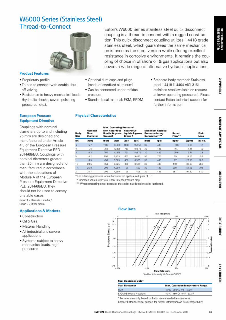
65
PNEU
MAT
ICSP
ECIA
L A
PPLI
CATI
ON
SD
IAG
NO
STIC
AG
RICU
LTU
RERE
FRIG
ERA
NT
FLU
ID T
RAN
SFER
AN
D H
YDRA
ULI
C
EATON Quick Disconnect Couplings EMEA E-MEQD-CC002-E4 December 2018
Physical Characteristics
Max. Operating Pressure*
Body Size
NominalFlow Diameter
Non hazardous liquids & gases Group 2
Hazardous liquids & gases Group 1
Maximum Residual Pressure during Connection***
RatedFlow**
FluidLoss
(in) (mm) (bar) (psi) (bar) (psi) (bar) (psi) (lpm) (gpm) ml-cc.
¼ 5.7 1100 15,950 1100 15,950 30 435 11.6 3.06 1.1
7.6 750 10,875 750 10,875 30 435 16.7 4.41 1.9
½ 10.3 750 10,875 750 10,875 30 435 25.5 6.74 2.8
¾ 14.2 650 9,425 650 9,425 50 725 55 14.53 5.8
1 16.5 450 6,525 450 6,525 30 435 87 22.98 10.9
1¼ 20.5 450 6,525 450 6,525 30 435 140 36.98 26.9
1½ 25.8 300 4,350 38 550 30 435 208 54.95 37.5
2 34.7 300 4,350 28 405 30 435 357 94.30 81.0
* For pulsating pressures when disconnected apply a multiplier of 0.5** Indicated values refer to a 1 bar/14.5 psi pressure drop.*** When connecting under pressure, the socket nut thread must be lubricated.
• Proprietary profile• Thread-to-connect with double shut-
off valving• Resistance to heavy mechanical loads
(hydraulic shocks, severe pulsating pressures, etc.).
• Optional dust caps and plugs (made of anodized aluminum)
• Can be connected under residual pressure
• Standard seal material: FKM, EPDM
• Standard body material: Stainless steel 1.4418 (1.4404 AISI 316L stainless steel available on request at lower operating pressures). Please contact Eaton technical support for further information
Product Features
Eaton’s W6000 Series stainless steel quick disconnect coupling is a thread-to-connect with a rugged construc-tion. This quick disconnect coupling utilizes 1.4418 grade stainless steel, which guarantees the same mechanical resistance as the steel version while offering excellent resistance in corrosive environments. It remains the cou-pling of choice in offshore oil & gas applications but also covers a wide range of alternative hydraulic applications.
Seal Elastomer Data*
Seal Elastomer Max. Operation Temperature Range
FKM -20°C +200°C/-4°F +392°F
EPDM (Ethylene-Propylene) -40°C +150°C/-40°F +302°F
* For reference only, based on Eaton recommended temperatures.Contact Eaton technical support for further information on fluid compatibility.
Couplings with nominal diameters up to and including 25 mm are designed and manufactured under Article 4.3 of the European Pressure Equipment Directive PED 2014/68/EU. Couplings with nominal diameters greater than 25 mm are designed and manufactured in accordance with the stipulations of Module A of the European Pressure Equipment Directive PED 2014/68/EU. They should not be used to convey unstable gases.Group 1 = Hazardous media /Group 2 = Other media
European Pressure Equipment Directive
Applications & Markets• Construction• Oil & Gas• Material Handling• All industrial and severe
applications• Systems subject to heavy
mechanical loads, high pressures
0.264 2.64 26.4 0.1
1
0.5
0.3
0.2
54
3
1 10 100 1000
Flow Rate (gpm)
Pre
ssu
re d
rop
(P
SI)
Pre
ssu
re D
rop
(b
ar)
Flow Rate (l/min)
72.5
1.45
14.5
43.5
4.35
7.25
58
29
2.9
2
264
1/4
3/8
1/2
3/4
1" 1
/4
1" 1
/2
1 2
Test Fluid: Oil viscosity 30 cSt at 40°C/104°F
W6000 Series (Stainless Steel)Thread-to-Connect
Flow Data
Pre
ssu
re D
rop
, psi

66
FLUID
TRAN
SFERA
ND
HYD
RAU
LICPN
EUM
ATICSPECIA
L APPLICATIO
NS
DIA
GN
OSTIC
AG
RICULTU
REREFRIG
ERAN
T
EATON Quick Disconnect Couplings EMEA E-MEQD-CC002-E4 December 2018
W6000 Series (Stainless Steel)Thread-to-Connect
Sockets (Female)
Part Number*Body Size
Nominal Flow Diameter
Thread Size** (Female) Dimensions Weight
FKM EPDM (in) (mm) NPT BSPP Fig. A (in)
B (in)
C (in)
Across Flats (in)
Hex(in)
A (mm)
B (mm)
C (mm)
Across Flats (mm)
Hex (mm)
lbs grams
WV06017V0 WV06017E0 ¼ 5.7 - ¼-19 1 2.09 1.38 0.83 0.75 1.26 53 35 21 19 32 0.32 144
WV06217V0 WV06217E0 ¼ 5.7 ¼-18 - 1 2.09 1.38 0.83 0.75 1.26 53 35 21 19 32 0.32 144
WV06027V0 WV06027E0 7.6 - -19 1 2.56 1.50 0.98 0.90 1.38 65 38 25 23 35 0.48 217
WV06227V0 WV06227E0 7.6 -18 - 1 2.56 1.50 0.98 0.90 1.38 65 38 25 23 35 0.48 217
WV06037V0 WV06037E0 ½ 10.3 - ½-14 1 2.91 1.77 1.14 1.06 1.61 74 45 29 27 41 0.71 320
WV06237V0 WV06237E0 ½ 10.3 ½-14 - 1 2.91 1.77 1.14 1.06 1.61 74 45 29 27 41 0.71 320
WV06047V0 WV06047E0 ¾ 14.2 - ¾-14 1 3.58 2.16 1.50 1.38 1.97 91 55 38 35 50 1.32 600
WV06247V0 WV06247E0 ¾ 14.2 ¾-14 - 1 3.58 2.16 1.50 1.38 1.97 91 55 38 35 50 1.32 600
WV06057V0 WV06057E0 1 16.5 - 1-11 1 4.05 2.72 1.81 1.61 2.56 103 69 46 41 65 2.41 1092
WV06257V0 WV06257E0 1 16.5 1-11½ - 1 4.05 2.72 1.81 1.61 2.56 103 69 46 41 65 2.41 1092
WV06067V0 WV06067E0 1¼ 20.5 - 1¼-11 1 5.71 3.50 2.36 2.16 3.03 145 89 60 55 77 6.13 2780
WV06267V0 WV06267E0 1¼ 20.5 1¼-11½ - 1 5.71 3.50 2.36 2.16 3.03 145 89 60 55 77 6.13 2780
WV06077V0 WV06077E0 1½ 25.8 - 1½-11 1 6.81 3.94 2.64 2.48 3.46 173 100 67 63 88 9.26 4200
WV06277V0 WV06277E0 1½ 25.8 1½-11½ - 1 6.81 3.94 2.64 2.48 3.46 173 100 67 63 88 9.26 4200
WV06097V0 WV06097E0 2 34.7 - 2-11 1 8.07 4.60 3.07 2.80 4.13 205 117 78 71 105 14.64 6640
WV06297V0 WV06297E0 2 34.7 2-11½ - 1 8.07 4.60 3.07 2.80 4.13 205 117 78 71 105 14.64 6640
* 1.4404 AISI 316L stainless steel available on request. Please contact Eaton technical support for further information.** Alternative end connections available upon request.To obtain connected length of coupling add dimensions A (Fig.1) and G (Fig. 2) together.
Plugs (Male)
Part Number*Body Size
Nominal Flow Diameter
Thread Size** (Female) Dimensions Weight
FKM EPDM (in) (mm) NPT BSPP Fig. D (in)
E (in)
F (in)
G (in)
Across Flats (in)
D (mm)
E (mm)
F (mm)
G (mm)
Across Flats (mm)
lbs grams
WV06014V0 WV06014E0 ¼ 5.7 - ¼-19 2 1.38 0.59 0.90 0.45 0.75 35 15 23 11.5 19 0.16 71
WV06214V0 WV06214E0 ¼ 5.7 ¼-18 - 2 1.38 0.59 0.90 0.45 0.75 35 15 23 11.5 19 0.16 71
WV06024V0 WV06024E0 7.6 - -19 2 1.65 0.75 1.02 0.52 0.90 42 19 26 13 23 0.23 104
WV06224V0 WV06224E0 7.6 -18 - 2 1.65 0.75 1.02 0.52 0.90 42 19 26 13 23 0.23 104
WV06034V0 WV06034E0 ½ 10.3 - ½-14 2 1.97 0.87 1.26 0.77 1.06 50 22 32 19.5 27 0.36 165
WV06234V0 WV06234E0 ½ 10.3 ½-14 - 2 1.97 0.87 1.26 0.77 1.06 50 22 32 19.5 27 0.36 165
WV06044V0 WV06044E0 ¾ 14.2 - ¾-14 2 2.48 1.14 1.65 1.02 1.38 63 29 42 26 35 0.84 382
WV06244V0 WV06244E0 ¾ 14.2 ¾-14 - 2 2.48 1.14 1.65 1.02 1.38 63 29 42 26 35 0.84 382
WV06054V0 WV06054E0 1 16.5 - 1-11 2 2.80 1.42 1.89 1.14 1.61 71 36 48 29 41 1.29 585
WV06254V0 WV06254E0 1 16.5 1-11½ - 2 2.80 1.42 1.89 1.14 1.61 71 36 48 29 41 1.29 585
WV06064V0 WV06064E0 1¼ 20.5 - 1¼-11 2 3.82 2.00 2.36 1.45 2.16 97 50.9 60 37 55 3.22 1460
WV06264V0 WV06264E0 1¼ 20.5 1¼-11½ - 2 3.82 2.00 2.36 1.45 2.16 97 50.9 60 37 55 3.22 1460
WV06074V0 WV06074E0 1½ 25.8 - 1½-11 2 4.29 2.24 2.64 1.22 2.48 109 56.9 67 31 63 4.50 2040
WV06274V0 WV06274E0 1½ 25.8 1½-11½ - 2 4.29 2.24 2.64 1.22 2.48 109 56.9 67 31 63 4.50 2040
WV06094V0 WV06094E0 2 34.7 - 2-11 2 5.08 2.73 3.07 1.32 2.80 129 69.4 78 33.5 71 7.05 3200
WV06294V0 WV06294E0 2 34.7 2-11½ - 2 5.08 2.73 3.07 1.32 2.80 129 69.4 78 33.5 71 7.05 3200
* 1.4404 AISI 316L stainless steel available on request. Please contact Eaton technical support for further information.** Alternative end connections available upon request.To obtain connected length of coupling add dimensions A (Fig.1) and G (Fig. 2) together.
A
BC
Across �ats Hex
DG
FE
Across flats
Figure 1
Figure 2

67
PNEU
MAT
ICSP
ECIA
L A
PPLI
CATI
ON
SD
IAG
NO
STIC
AG
RICU
LTU
RERE
FRIG
ERA
NT
FLU
ID T
RAN
SFER
AN
D H
YDRA
ULI
C
EATON Quick Disconnect Couplings EMEA E-MEQD-CC002-E4 December 2018
Dust Plugs and Dust CapsBody Size Socket Dust Plug Part Number Plug Dust Cap Part Number
(in) Anodized Aluminum Anodized Aluminum
¼ WD0611700 WD0611400
WD0612700 WD0612400
½ WD0613700 WD0613400
¾ WD0614700 WD0614400
1 WD0615700 WD0615400
1¼ WD0616700 WD0616400
1½ WD0617700 WD0617400
2 WD0619700 WD0619400
W6000 Series (Stainless Steel)Thread-to-Connect
Seal kit for servicing sockets (Female)
Body Size Seal & Back-up Ring Kit* Qty
(in) NBR seals & PTFE back-up rings
FKM seals & PTFE back-up rings
1/4 WG0601700 WG06017V0 50 O-rings + 50 Backup rings
3/8 WG0602700 WG06027V0 50 O-rings + 50 Backup rings
1/2 WG0603700 WG06037V0 50 O-rings + 50 Backup rings
3/4 WG0604700 WG06047V0 50 O-rings + 50 Backup rings
1 WG0605700 WG06057V0 50 O-rings + 50 Backup rings
1 1/4 WG0606700 WG06067V0 15 O-rings + 15 Backup rings
1 1/2 WG0607700 WG06077V0 15 O-rings + 15 Backup rings
2 WG0609700 WG06097V0 15 O-rings + 15 Backup rings
*The valve seal is not included in our repair kits
EPDM seals (-40°C/+150°C) are also available but kit part number doesn’t exist. Please ask our technical support in case you need this compound.
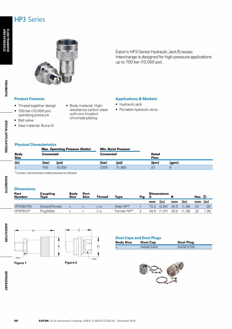
68
FLUID
TRAN
SFERA
ND
HYD
RAU
LICPN
EUM
ATICSPECIA
L APPLICATIO
NS
DIA
GN
OSTIC
AG
RICULTU
REREFRIG
ERAN
T
EATON Quick Disconnect Couplings EMEA E-MEQD-CC002-E4 December 2018
HP3 Series
Eaton’s HP3 Series Hydraulic Jack/Enerpac Interchange is designed for high-pressure applications up to 700 bar (10,000 psi).
Applications & Markets• Hydraulic jack• Portable hydraulic rams
• Thread together design• 700 bar (10,000 psi)
operating pressure• Ball valve• Seal material: Buna-N
• Body material: High- resistance carbon steel with zinc trivalent chromate plating
Product Features
Part Coupling Body Port Dimensions Number Type Size Size Thread Type Fig. A B Hex
mm (in) mm (in) mm (in)HP3SB37M Socket/Female -18 Male NPT 1 72.2 (2.84) 35.0 (1.38) 24 .94HP3PB37F Plug/Male -18 Female NPT 2 40.0 (1.57) 35.0 (1.38) 32 1.26
Dimensions
1
Physical Characteristics Max. Operating Pressure (Static) Min. Burst Pressure
Body Connected Connected Rated Size Flow
(in) (bar) (psi) (bar) (psi) (lpm) (gpm) 700 10,000 2200 31,900 23 6
* Connect and disconnect under pressure not allowed
Figure 1 Figure 2
Dust Caps and Dust Plugs Body Size Dust Cap Dust Plug
WA5612400 WA5612700B
A
D
C
HEX HEX
B
A
D
C
HEX HEX
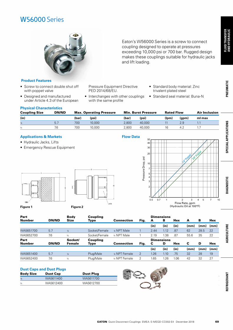
69
PNEU
MAT
ICSP
ECIA
L A
PPLI
CATI
ON
SD
IAG
NO
STIC
AG
RICU
LTU
RERE
FRIG
ERA
NT
FLU
ID T
RAN
SFER
AN
D H
YDRA
ULI
C
EATON Quick Disconnect Couplings EMEA E-MEQD-CC002-E4 December 2018
Applications & Markets• Hydraulic Jacks, Lifts• Emergency Rescue Equipment
Part Body Coupling Dimensions Number DN/ND Size Type Connection Fig. A B Hex A B Hex
(in) (in) (in) (mm) (mm) (mm)
WA5651700 5.7 ¼ Socket/Female ¼ NPT Male 1 2.44 1.12 .87 62 28.5 22 WA5652700 7.6 Socket/Female NPT Male 1 2.19 1.38 .87 55.6 35 22Part Socket/ Coupling Dimensions Number DN/ND Female Type Connection Fig. C D Hex C D Hex
(in) (in) (in) (mm) (mm) (mm)
WA5651400 5.7 ¼ Plug/Male ¼ NPT Female 2 1.26 1.10 .75 32 28 19 WA5652400 7.6 Plug/Male NPT Female 2 1.65 1.26 1.06 42 32 27
Dust Caps and Dust Plugs Body Size Dust Cap Dust Plug¼ WA5611400 WA5611700
WA5612400 WA5612700
Figure 1
Eaton’s W56000 Series is a screw to connect coupling designed to operate at pressures exceeding 10,000 psi or 700 bar. Rugged design makes these couplings suitable for hydraulic jacks and lift loading.
• Screw to connect double shut off with poppet valve
• Designed and manufactured under Article 4.3 of the European
Pressure Equipment Directive PED 2014/68/EU.
• Interchanges with other couplings with the same profile
• Standard body material: Zinc trivalent plated steel
• Standard seal material: Buna-N
Product Features
Physical Characteristics Coupling Size DN/ND Max. Operating Pressure Min. Burst Pressure Rated Flow Air Inclusion
(in) (bar) (psi) (bar) (psi) (lpm) (gpm) ml max
¼ 5.7 700 10,000 2,800 40,000 11 2.9 1.1 7.6 700 10,000 2,800 40,000 16 4.2 1.7
W56000 Series
Figure 2
Flow Data
Pre
ssu
re D
rop
, psi
Flow Rate, gpm(Hydraulic Oil at 100°F)

70
FLUID
TRAN
SFERA
ND
HYD
RAU
LICPN
EUM
ATICSPECIA
L APPLICATIO
NS
DIA
GN
OSTIC
AG
RICULTU
REREFRIG
ERAN
T
EATON Quick Disconnect Couplings EMEA E-MEQD-CC002-E4 December 2018
FD35 Series 10,000 psi Ball Latch
Eaton’s FD35 Series ball latch has a greater surface contact area for long surface life in rugged high pressure applications. The maximum operating pressure is 10,000 psi.
Product Features• Safety sleeve lock
prevents accidental disconnection
• Heavy duty back-up ring prevents O-Ring extrusion
Physical Characteristics Body Max. Operating Min. Burst Vacuum Rated Air Fluid Size Pressure Pressure Connected Only Flow Inclusion Loss
(bar) (psi) (bar) (psi) (in./Hg) (lpm) (gpm) cc. max. cc.max.
700 10,000 2,800 40,000 28 8 2 0.50 0.50
• Heat-treated and plated steel for greater wear and corrosion resistance
• Self-sealing poppet valves provide excellent high-and low-pressure sealing
• Standard seal material: FKM• Standard body material:
High-resistance carbon steel with Zinc trivalent plating
Applications & Markets• 10,000 psi Hydraulic
Applications• Hydraulic Tool• Hydraulic Ram and Work
Loading
Flow DataPressure Drop Versus Flow Graph
Gallons Per Minute FlowTest Fluid: MIL-H-5606 Oil at 100°F
4 5 6 7 8 9 10 12 14 16 18 20 30 400.05
0.1
0.5
1
2
3
4
bar
lpm
1.056 2.64 5.28 7.92 10.56
0.725
1.45
7.25
14.5
29
43.5
58
gpm
psi3/8
Pre
ssu
re D
rop
, bar

71
PNEU
MAT
ICSP
ECIA
L A
PPLI
CATI
ON
SD
IAG
NO
STIC
AG
RICU
LTU
RERE
FRIG
ERA
NT
FLU
ID T
RAN
SFER
AN
D H
YDRA
ULI
C
EATON Quick Disconnect Couplings EMEA E-MEQD-CC002-E4 December 2018
FD35 Series 10,000 psi
Figure 2Figure 1 Figure 3
Dimensions (Female NPT, Valved)Part Coupling Body Port Dimensions Number Type Size Size Thread Type Fig. A B Hex 1
mm (in) mm (in) mm (in)FD35-1002-06-06 Plug/Male -18 Female NPT 1 53.8 (2.12) - - 23.9 (.94)FD35-1001-06-06 Socket/Female -18 Female NPT 2 65.0 (2.56) 32.3 (1.27) 23.9 (.94)FD35-1000-06-06 Complete -18 Female NPT 3 89.9 (3.54) - - - -
Dimensions (Female SAE O-Ring, Valved)Part Coupling Body Port Dimensions Number Type Size Size Thread Type Fig. A B Hex 1
mm (in) mm (in) mm (in)FD35-1008-06-06 Plug/Male 9/16 9/16-18 Female SAE O-Ring 1 53.8 (2.12) - - 23.9 (.94)FD35-1007-06-06 Socket/Female 9/16 9/16-18 Female SAE O-Ring 2 65.0 (2.56) 32.3 (1.27) 23.9 (.94)FD35-1006-06-06 Complete 9/16 9/16-18 Female SAE O-Ring 3 89.9 (3.54) - - - -
Dimensions (Female SAE O-Ring, 125 PSI Bleed Valve) Coupling Body Port Dimensions Part Number Type Size Size Thread Type Fig. A Hex 1
mm (in) mm (in)FD35-1052-06-06 Plug/Male 9/16 9/16-18 Female SAE O-Ring 1 53.8 (2.12) 23.9 (.94)
Note: Incorporates a special relief valve set at 125 psi, preventing disconnected pressure build-up.
Dust Cap/PlugPart Body Number Size
FD35-1042-06
Note: Fits male and female halves Dust Cap/Plug
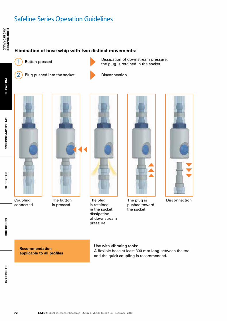
72
FLUID
TRAN
SFERA
ND
HYD
RAU
LICPN
EUM
ATICSPECIA
L APPLICATIO
NS
DIA
GN
OSTIC
AG
RICULTU
REREFRIG
ERAN
T
EATON Quick Disconnect Couplings EMEA E-MEQD-CC002-E4 December 2018
Safeline Series Operation Guidelines
Elimination of hose whip with two distinct movements:
Button pressedDissipation of downstream pressure: the plug is retained in the socket1
Plug pushed into the socket Disconnection2
Use with vibrating tooIs:A flexible hose at least 300 mm long between the tooland the quick coupling is recommended.
Recommendation applicable to all profiles
Couplingconnected
The buttonis pressed
The plugis retainedin the socket:dissipationof downstreampressure
The plug ispushed towardthe socket
Disconnection

73
PNEU
MAT
ICSP
ECIA
L A
PPLI
CATI
ON
SD
IAG
NO
STIC
AG
RICU
LTU
RERE
FRIG
ERA
NT
FLU
ID T
RAN
SFER
AN
D H
YDRA
ULI
C
EATON Quick Disconnect Couplings EMEA E-MEQD-CC002-E4 December 2018
Eaton’s Safeline Series is an Industrial Interchange pneumatic coupling with push button safety feature designed for use with compressed air. Two-step disconnect procedure shuts off air supply and releases downstream air pressure before plug can be removed from socket/female, which prevents hose whip.
• Safe and easy to connect and disconnect
• Light weight, compact ergonomic design
• Accepts 1/4” ISO 6150 Series B and A-A-59439 plugs/males
• Accepts all US industrial plugs/males
• Standard body material: Aluminum
• Standard seal material: Buna-N
Product Features
Safeline SeriesISO 6150 B GD10500 Safety-Type Quick-Release
Applications & Markets• General
Pneumatics• Air Tools• Industrial Plants• Maintenance
and Repair
Flow Data
Air flow-rate at 6 bar (87 psi)
Physical Characteristics Body Nominal Flow Max. Operating Pressure Air Flow Rate* Working Size Diameter Connected or Disconnected ∆p 0.6 bar/8.7 psi** ∆p 1 bar/14.5 psi*** Temperature
(mm) (bar) (psi) (lpm) (gpm) (lpm) (gpm) °C °F
¼ 5.5 16 232 525 139 660 174 -20° +100° -4° +212°
*Indicated values refer to an inlet pressure of 6 bar / 87 psi. **This flow rate allows the optimum output from a pneumatic tool. ** This flow rate is the maximum recommended for a suitable output from a pneumatic tool. For applications needing higher flow rates, it is recommended to select a larger
size coupling.
04624624.621.45
14.5
0.1
1
000010001001
Flow rate (gpm)
Pres
sure
dro
p (P
SI)
Pres
sure
dro
p (b
ar)
Flow rate (l/min)
0,2
0,3
0,5
29,0
2,90
4,35
7,25
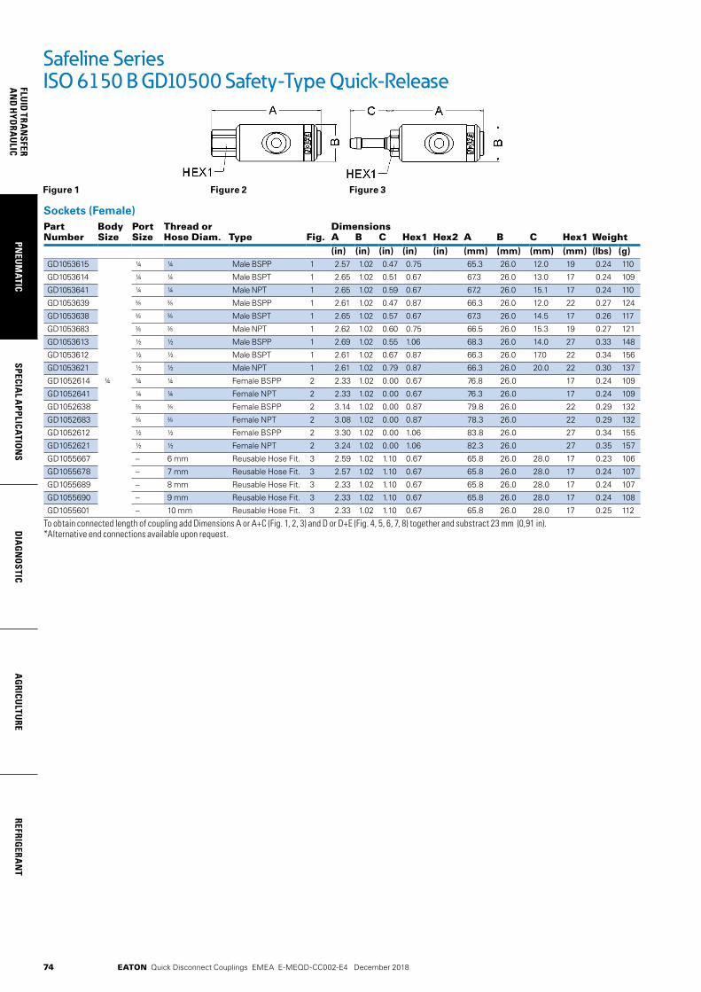
74
FLUID
TRAN
SFERA
ND
HYD
RAU
LICPN
EUM
ATICSPECIA
L APPLICATIO
NS
DIA
GN
OSTIC
AG
RICULTU
REREFRIG
ERAN
T
EATON Quick Disconnect Couplings EMEA E-MEQD-CC002-E4 December 2018
Figure 1 Figure 2 Figure 3
Sockets (Female)Part Body Port Thread or DimensionsNumber Size Size Hose Diam. Type Fig. A B C Hex1 Hex2 A B C Hex1 Weight
(in) (in) (in) (in) (in) (mm) (mm) (mm) (mm) (lbs) (g)GD1053615 ¼ ¼ Male BSPP 1 2.57 1.02 0.47 0.75 65.3 26.0 12.0 19 0.24 110
GD1053614 ¼ ¼ Male BSPT 1 2.65 1.02 0.51 0.67 67.3 26.0 13.0 17 0.24 109
GD1053641 ¼ ¼ Male NPT 1 2.65 1.02 0.59 0.67 67.2 26.0 15.1 17 0.24 110
GD1053639 Male BSPP 1 2.61 1.02 0.47 0.87 66.3 26.0 12.0 22 0.27 124
GD1053638 Male BSPT 1 2.65 1.02 0.57 0.67 67.3 26.0 14.5 17 0.26 117
GD1053683 Male NPT 1 2.62 1.02 0.60 0.75 66.5 26.0 15.3 19 0.27 121
GD1053613 ½ ½ Male BSPP 1 2.69 1.02 0.55 1.06 68.3 26.0 14.0 27 0.33 148
GD1053612 ½ ½ Male BSPT 1 2.61 1.02 0.67 0.87 66.3 26.0 17.0 22 0.34 156
GD1053621 ½ ½ Male NPT 1 2.61 1.02 0.79 0.87 66.3 26.0 20.0 22 0.30 137
GD1052614 ¼ ¼ ¼ Female BSPP 2 2.33 1.02 0.00 0.67 76.8 26.0 17 0.24 109
GD1052641 ¼ ¼ Female NPT 2 2.33 1.02 0.00 0.67 76.3 26.0 17 0.24 109
GD1052638 Female BSPP 2 3.14 1.02 0.00 0.87 79.8 26.0 22 0.29 132
GD1052683 Female NPT 2 3.08 1.02 0.00 0.87 78.3 26.0 22 0.29 132
GD1052612 ½ ½ Female BSPP 2 3.30 1.02 0.00 1.06 83.8 26.0 27 0.34 155
GD1052621 ½ ½ Female NPT 2 3.24 1.02 0.00 1.06 82.3 26.0 27 0.35 157
GD1055667 – 6 mm Reusable Hose Fit. 3 2.59 1.02 1.10 0.67 65.8 26.0 28.0 17 0.23 106
GD1055678 – 7 mm Reusable Hose Fit. 3 2.57 1.02 1.10 0.67 65.8 26.0 28.0 17 0.24 107
GD1055689 – 8 mm Reusable Hose Fit. 3 2.33 1.02 1.10 0.67 65.8 26.0 28.0 17 0.24 107
GD1055690 – 9 mm Reusable Hose Fit. 3 2.33 1.02 1.10 0.67 65.8 26.0 28.0 17 0.24 108
GD1055601 – 10 mm Reusable Hose Fit. 3 2.33 1.02 1.10 0.67 65.8 26.0 28.0 17 0.25 112
To obtain connected length of coupling add Dimensions A or A+C (Fig. 1, 2, 3) and D or D+E (Fig. 4, 5, 6, 7, 8) together and substract 23 mm (0,91 in). *Alternative end connections available upon request.
Safeline SeriesISO 6150 B GD10500 Safety-Type Quick-Release
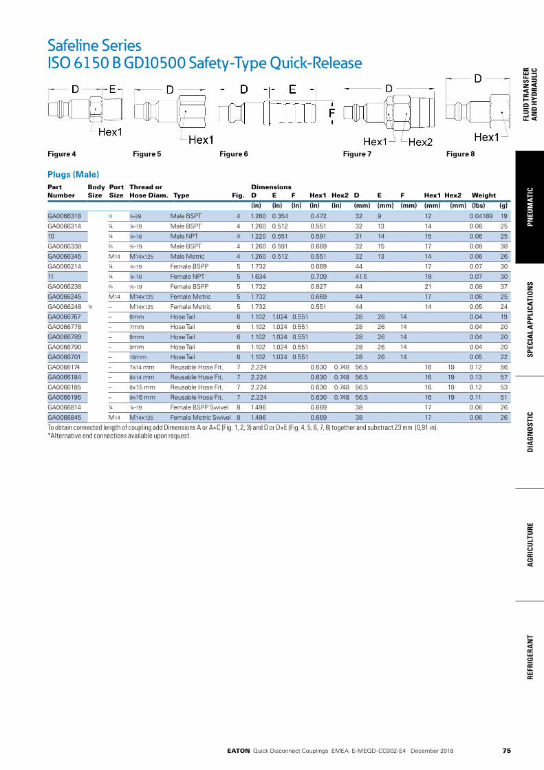
75
PNEU
MAT
ICSP
ECIA
L A
PPLI
CATI
ON
SD
IAG
NO
STIC
AG
RICU
LTU
RERE
FRIG
ERA
NT
FLU
ID T
RAN
SFER
AN
D H
YDRA
ULI
C
EATON Quick Disconnect Couplings EMEA E-MEQD-CC002-E4 December 2018
Figure 4 Figure 5 Figure 6 Figure 7 Figure 8
Plugs (Male)Part Body Port Thread or DimensionsNumber Size Size Hose Diam. Type Fig. D E F Hex1 Hex2 D E F Hex1 Hex2 Weight
(in) (in) (in) (in) (in) (mm) (mm) (mm) (mm) (mm) (lbs) (g)
GA0066318 -28 Male BSPT 4 1.260 0.354 0.472 32 9 12 0.04189 19
GA0066314 ¼ ¼-19 Male BSPT 4 1.260 0.512 0.551 32 13 14 0.06 25
10 ¼ ¼-18 Male NPT 4 1.220 0.551 0.591 31 14 15 0.06 25
GA0066338 -19 Male BSPT 4 1.260 0.591 0.669 32 15 17 0.08 38
GA0066345 M14 M14x125 Male Metric 4 1.260 0.512 0.551 32 13 14 0.06 26
GA0066214 ¼ ¼-19 Female BSPP 5 1.732 0.669 44 17 0.07 30
11 ¼ ¼-18 Female NPT 5 1.634 0.709 41.5 18 0.07 30
GA0066238 -19 Female BSPP 5 1.732 0.827 44 21 0.08 37
GA0066245 M14 M14x125 Female Metric 5 1.732 0.669 44 17 0.06 25
GA0066248 ¼ – M14x125 Female Metric 5 1.732 0.551 44 14 0.05 24
GA0066767 – 6mm Hose Tail 6 1.102 1.024 0.551 28 26 14 0.04 19
GA0066778 – 7mm Hose Tail 6 1.102 1.024 0.551 28 26 14 0.04 20
GA0066789 – 8mm Hose Tail 6 1.102 1.024 0.551 28 26 14 0.04 20
GA0066790 – 9mm Hose Tail 6 1.102 1.024 0.551 28 26 14 0.04 20
GA0066701 – 10mm Hose Tail 6 1.102 1.024 0.551 28 26 14 0.05 22
GA0066174 – 7x14 mm Reusable Hose Fit. 7 2.224 0.630 0.748 56.5 16 19 0.12 56
GA0066184 – 8x14 mm Reusable Hose Fit. 7 2.224 0.630 0.748 56.5 16 19 0.13 57
GA0066185 – 8x15 mm Reusable Hose Fit. 7 2.224 0.630 0.748 56.5 16 19 0.12 53
GA0066196 – 9x16 mm Reusable Hose Fit. 7 2.224 0.630 0.748 56.5 16 19 0.11 51
GA0066814 ¼ ¼-19 Female BSPP Swivel 8 1.496 0.669 38 17 0.06 26
GA0066845 M14 M14x125 Female Metric Swivel 8 1.496 0.669 38 17 0.06 26
To obtain connected length of coupling add Dimensions A or A+C (Fig. 1, 2, 3) and D or D+E (Fig. 4, 5, 6, 7, 8) together and substract 23 mm (0,91 in). *Alternative end connections available upon request.
Safeline SeriesISO 6150 B GD10500 Safety-Type Quick-Release
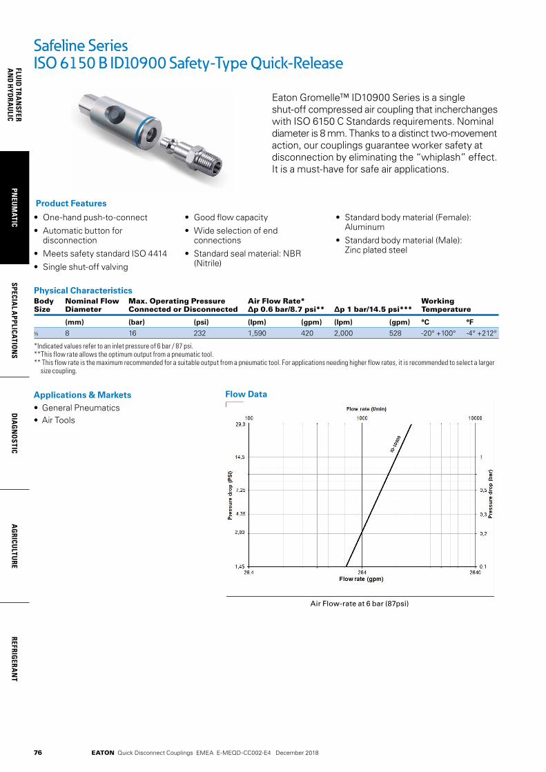
76
FLUID
TRAN
SFERA
ND
HYD
RAU
LICPN
EUM
ATICSPECIA
L APPLICATIO
NS
DIA
GN
OSTIC
AG
RICULTU
REREFRIG
ERAN
T
EATON Quick Disconnect Couplings EMEA E-MEQD-CC002-E4 December 2018
Safeline SeriesISO 6150 B ID10900 Safety-Type Quick-Release
Eaton Gromelle™ ID10900 Series is a single shut-off compressed air coupling that incherchanges with ISO 6150 C Standards requirements. Nominal diameter is 8 mm. Thanks to a distinct two-movement action, our couplings guarantee worker safety at disconnection by eliminating the “whiplash” effect. It is a must-have for safe air applications.
• One-hand push-to-connect
• Automatic button for disconnection
• Meets safety standard ISO 4414
• Single shut-off valving
• Good flow capacity
• Wide selection of end connections
• Standard seal material: NBR (Nitrile)
• Standard body material (Female): Aluminum
• Standard body material (Male): Zinc plated steel
Product Features
Applications & Markets• General Pneumatics• Air Tools
Flow Data
Physical Characteristics Body Nominal Flow Max. Operating Pressure Air Flow Rate* Working Size Diameter Connected or Disconnected ∆p 0.6 bar/8.7 psi** ∆p 1 bar/14.5 psi*** Temperature
(mm) (bar) (psi) (lpm) (gpm) (lpm) (gpm) °C °F
8 16 232 1,590 420 2,000 528 -20° +100° -4° +212°
*Indicated values refer to an inlet pressure of 6 bar / 87 psi. **This flow rate allows the optimum output from a pneumatic tool. ** This flow rate is the maximum recommended for a suitable output from a pneumatic tool. For applications needing higher flow rates, it is recommended to select a larger
size coupling.
Air Flow-rate at 6 bar (87psi)
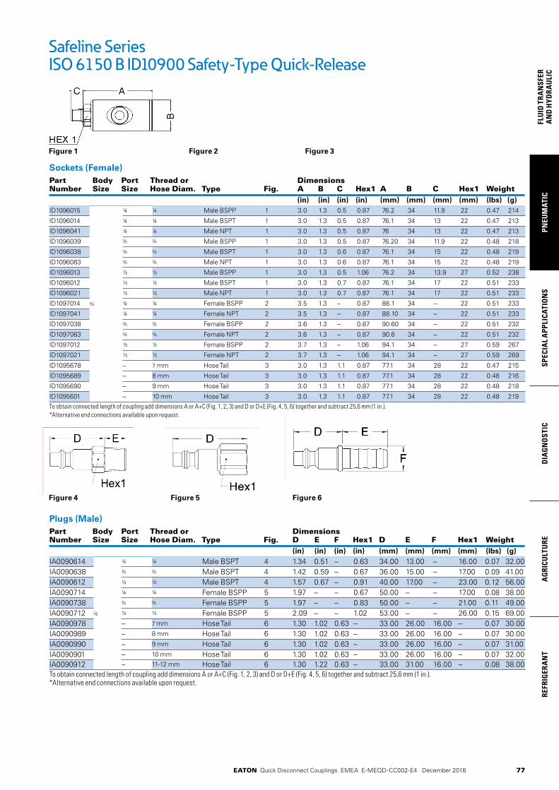
77
PNEU
MAT
ICSP
ECIA
L A
PPLI
CATI
ON
SD
IAG
NO
STIC
AG
RICU
LTU
RERE
FRIG
ERA
NT
FLU
ID T
RAN
SFER
AN
D H
YDRA
ULI
C
EATON Quick Disconnect Couplings EMEA E-MEQD-CC002-E4 December 2018
Safeline SeriesISO 6150 B ID10900 Safety-Type Quick-Release
Figure 1 Figure 2 Figure 3
Sockets (Female)Part Body Port Thread or DimensionsNumber Size Size Hose Diam. Type Fig. A B C Hex1 A B C Hex1 Weight
(in) (in) (in) (in) (mm) (mm) (mm) (mm) (lbs) (g)ID1096015 ¼ ¼ Male BSPP 1 3.0 1.3 0.5 0.87 76.2 34 11.9 22 0.47 214
ID1096014 ¼ ¼ Male BSPT 1 3.0 1.3 0.5 0.87 76.1 34 13 22 0.47 213
ID1096041 ¼ ¼ Male NPT 1 3.0 1.3 0.5 0.87 76 34 13 22 0.47 213
ID1096039 Male BSPP 1 3.0 1.3 0.5 0.87 76.20 34 11.9 22 0.48 218
ID1096038 Male BSPT 1 3.0 1.3 0.6 0.87 76.1 34 15 22 0.48 219
ID1096083 Male NPT 1 3.0 1.3 0.6 0.87 76.1 34 15 22 0.48 219
ID1096013 ½ ½ Male BSPP 1 3.0 1.3 0.5 1.06 76.2 34 13.9 27 0.52 238
ID1096012 ½ ½ Male BSPT 1 3.0 1.3 0.7 0.87 76.1 34 17 22 0.51 233
ID1096021 ½ ½ Male NPT 1 3.0 1.3 0.7 0.87 76.1 34 17 22 0.51 233
ID1097014 ¼ ¼ Female BSPP 2 3.5 1.3 – 0.87 88.1 34 – 22 0.51 233
ID1097041 ¼ ¼ Female NPT 2 3.5 1.3 – 0.87 88.10 34 – 22 0.51 233
ID1097038 Female BSPP 2 3.6 1.3 – 0.87 90.60 34 – 22 0.51 232
ID1097083 Female NPT 2 3.6 1.3 – 0.87 90.6 34 – 22 0.51 232
ID1097012 ½ ½ Female BSPP 2 3.7 1.3 – 1.06 94.1 34 – 27 0.59 267
ID1097021 ½ ½ Female NPT 2 3.7 1.3 – 1.06 94.1 34 – 27 0.59 269
ID1095678 – 7 mm Hose Tail 3 3.0 1.3 1.1 0.87 77.1 34 28 22 0.47 215
ID1095689 – 8 mm Hose Tail 3 3.0 1.3 1.1 0.87 77.1 34 28 22 0.48 216
ID1095690 – 9 mm Hose Tail 3 3.0 1.3 1.1 0.87 77.1 34 28 22 0.48 218
ID1095601 – 10 mm Hose Tail 3 3.0 1.3 1.1 0.87 77.1 34 28 22 0.48 219To obtain connected length of coupling add dimensions A or A+C (Fig. 1, 2, 3) and D or D+E (Fig. 4, 5, 6) together and subtract 25,6 mm (1 in.). *Alternative end connections available upon request.
Plugs (Male)Part Body Port Thread or DimensionsNumber Size Size Hose Diam. Type Fig. D E F Hex1 D E F Hex1 Weight
(in) (in) (in) (in) (mm) (mm) (mm) (mm) (lbs) (g)IA0090614 ¼ ¼ Male BSPT 4 1.34 0.51 – 0.63 34.00 13.00 – 16.00 0.07 32.00IA0090638 Male BSPT 4 1.42 0.59 – 0.67 36.00 15.00 – 17.00 0.09 41.00IA0090612 ½ ½ Male BSPT 4 1.57 0.67 – 0.91 40.00 17.00 – 23.00 0.12 56.00IA0090714 ¼ ¼ Female BSPP 5 1.97 – – 0.67 50.00 – – 17.00 0.08 38.00IA0090738 Female BSPP 5 1.97 – – 0.83 50.00 – – 21.00 0.11 49.00IA0090712 ½ ½ Female BSPP 5 2.09 – – 1.02 53.00 – – 26.00 0.15 69.00IA0090978 – 7 mm Hose Tail 6 1.30 1.02 0.63 – 33.00 26.00 16.00 – 0.07 30.00IA0090989 – 8 mm Hose Tail 6 1.30 1.02 0.63 – 33.00 26.00 16.00 – 0.07 30.00IA0090990 – 9 mm Hose Tail 6 1.30 1.02 0.63 – 33.00 26.00 16.00 – 0.07 31.00IA0090901 – 10 mm Hose Tail 6 1.30 1.02 0.63 – 33.00 26.00 16.00 – 0.07 32.00IA0090912 – 11-12 mm Hose Tail 6 1.30 1.22 0.63 – 33.00 31.00 16.00 – 0.08 38.00To obtain connected length of coupling add dimensions A or A+C (Fig. 1, 2, 3) and D or D+E (Fig. 4, 5, 6) together and subtract 25,6 mm (1 in.).*Alternative end connections available upon request.
Figure 4 Figure 5 Figure 6

78
FLUID
TRAN
SFERA
ND
HYD
RAU
LICPN
EUM
ATICSPECIA
L APPLICATIO
NS
DIA
GN
OSTIC
AG
RICULTU
REREFRIG
ERAN
T
EATON Quick Disconnect Couplings EMEA E-MEQD-CC002-E4 December 2018
Eaton's Safeline Series is an Industrial Interchange pneumatic coupling with push button safety feature designed for use with compressed air. Two-step disconnect procedure shuts off air supply and releases downstream air pressure before plug can be removed from socket/female, which prevents hose whip.
• Safe and easy to connect and disconnect
• Light weight, compact ergonomic design
• Meets Safety Standard ISO 4414
• Meets ISO 6150 Series C Standard
• Standard body material: Dural
• Standard seal material: Buna-N
Product Features
Safeline SeriesISO 6150 C GD18500/GK18600
Applications & Markets• General Pneumatics • Air Tools • Industrial Plants • Maintenance and Repair
Flow Data
Physical Characteristics Body Nominal Flow Max. Operating Pressure Air Flow Rate* Working Size Diameter Connected or Disconnected ∆p 0.6 bar/8.7 psi** ∆p 1 bar/14.5 psi*** Temperature
(mm) (bar) (psi) (lpm) (gpm) (lpm) (gpm) °C °F
¼ 5.5 16 232 515 136 650 172 -20° +100° -4° +212°
*Indicated values refer to an inlet pressure of 6 bar / 87 psi. **This flow rate allows the optimum output from a pneumatic tool. ** This flow rate is the maximum recommended for a suitable output from a pneumatic tool. For applications needing higher flow rates, it is recommended to select a larger
size coupling.
Air flow-rate at 6 bar (87 psi)
04624624.621.45
14.5
0.1
1
000010001001
Flow rate (gpm)
Pres
sure
dro
p (P
SI)
Pres
sure
dro
p (b
ar)
Flow rate (l/min)
29,0
2,90
4,35
7,25
2
0,2
0,3
0,5

79
PNEU
MAT
ICSP
ECIA
L A
PPLI
CATI
ON
SD
IAG
NO
STIC
AG
RICU
LTU
RERE
FRIG
ERA
NT
FLU
ID T
RAN
SFER
AN
D H
YDRA
ULI
C
EATON Quick Disconnect Couplings EMEA E-MEQD-CC002-E4 December 2018
Safeline SeriesISO 6150 C GD18500/GK18600
Figure 1 Figure 2
Figure 5 Figure 6
Sockets (Female)Part Body Port Thread or DimensionsNumber Size Size Hose Diam. Type Fig. A B C Hex1 A B C Hex1 Weight
(in) (in) (in) (in) (mm) (mm) (mm) (mm) (lbs) (g)GD1853615 ¼ ¼ Male BSPP 1 1.85 1.02 0.47 0.75 47 26 12 19 0.17 77
GD1853614 ¼ ¼ Male BSPT 1 1.93 1.02 0.51 0.67 49 26 13 17 0.17 76
GD1853639 Male BSPP 1 1.89 1.02 0.47 0.87 48 26 12 22 0.20 91
GD1853638 Male BSPT 1 1.93 1.02 0.57 0.67 49 26 14.5 17 0.19 84
GD1853613 ½ ½ Male BSPP 1 1.97 1.02 0.55 1.06 50 26 14 27 0.25 115
GD1853612 ½ ½ Male BSPT 1 1.89 1.02 0.67 0.87 48 26 17 22 0.27 123
GD1852614 ¼ ¼ Female BSPP 2 2.30 1.02 0.67 58.5 26 – 17 0.17 76
GD1852638 ¼ Female BSPP 2 2.42 1.02 0.87 61.5 26 – 22 0.22 99
GD1852612 ½ ½ Female BSPP 2 2.58 1.02 1.06 65.5 26 – 27 0.27 122
GD1855667 – 6 mm Hose Tail 3 1.87 1.02 1.10 0.67 47.5 26 28 17 0.16 73
GD1855678 – 7 mm Hose Tail 3 1.87 1.02 1.10 0.67 47.5 26 28 17 0.16 74
GD1855689 – 8 mm Hose Tail 3 1.87 1.02 1.10 0.67 47.5 26 28 17 0.16 74
GD1855690 – 9 mm Hose Tail 3 1.87 1.02 1.10 0.67 47.5 26 28 17 0.17 75
GD1855601 – 10 mm Hose Tail 3 1.87 1.02 1.10 0.67 47.5 26 28 17 0.17 79
GD1855613 – 13 mm Hose Tail 3 1.87 1.02 1.30 0.67 47.5 26 33 17 0.19 87
GD1855014 ¼ ¼ Female BSPP, Bulkhead* 4 1.83 1.02 0.67 1.06 46.5 26 17 27 0.25 112
GD1855038 Female BSPP, Bulkhead** 4 1.87 1.02 0.79 1.26 47.5 26 20 32 0.33 150To obtain connected length of coupling add Dimensions A or A+C (Fig. 1, 2, 3, 4) and D or D+E (Fig. 5, 6, 7) together and substract 26 mm (1,02 in). *Max bulkhead thickness: 10 mm (0,39 in) / Bulkhead hole diameter = 21 mm (0,83 in). **Max bulkhead thickness: 12 mm (0,47 in) / Bulkhead hole diameter = 25 mm (0,98 in)
Figure 3 Figure 4
Plugs (Male)Part Body Port Thread or DimensionsNumber Size Size Hose Diam. Type Fig. D E F Hex1 Hex2 D E F Hex1 Hex2 Weight
(in) (in) (in) (in) (in) (mm) (mm) (mm) (mm) (mm) (lbs) (g)
GK1866319 Male BSPP 5 1.38 0.31 0.55 35 8 14 0.04 17GK1866318 Male BSPT 5 1.34 0.31 0.47 34 8 12 0.03 14GK1866381 Male NPT 5 1.34 0.39 0.47 34 10 12 0.03 15GK1866315 ¼ ¼ Male BSPP 5 1.42 0.47 0.67 36 12 17 0.06 25GK1866314 ¼ ¼ Male BSPT 5 1.40 0.51 0.55 35.5 13 14 0.05 23GK1866341 ¼ ¼ Male NPT 5 1.42 0.59 0.67 36 15 17 0.07 30GK1866339 Male BSPP 5 1.46 0.47 0.87 37 12 22 0.09 39GK1866338 Male BSPT 5 1.48 0.47 0.75 37.5 12 19 0.08 37GK1866218 Female BSPP 6 1.63 0.55 41.5 14 0.04 18GK1866281 ¼ Female NPT 6 0.00 0.00 0.04 18GK1866214 ¼ ¼ Female BSPP 6 1.97 0.67 50 17 0.07 33GK1866241 ¼ ¼ Female NPT 6 1.97 0.67 50 17 0.07 32GK1866238 Female BSPP 6 1.85 0.83 47 21 0.08 35GK1866245 M 14 M 14 x 125 Female Metric 6 1.87 0.67 47.5 17 0.06 26GK1866767 – 6 mm Hose Tail 7 1.26 1.10 0.59 32 28 15 0.03 15GK1866778 – 7 mm Hose Tail 7 1.26 1.10 0.59 32 28 15 0.04 18GK1866789 – 8 mm Hose Tail 7 1.26 1.10 0.59 32 28 15 0.04 19GK1866790 – 9 mm Hose Tail 7 1.26 1.10 0.59 32 28 15 0.04 19GK1866701 – 10 mm Hose Tail 7 1.26 1.10 0.59 32 28 15 0.04 20GK1866713 – 13 mm Hose Tail 7 1.26 1.30 0.79 32 33 20 0.08 34To obtain connected length of coupling add Dimensions A or A+C (Fig. 1, 2, 3, 4) and D or D+E (Fig. 5, 6, 7) together and substract 26 mm (1,02 in).
Figure 7
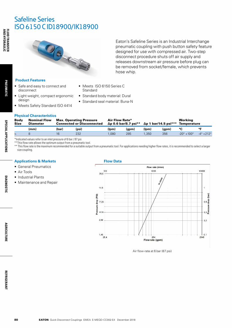
80
FLUID
TRAN
SFERA
ND
HYD
RAU
LICPN
EUM
ATICSPECIA
L APPLICATIO
NS
DIA
GN
OSTIC
AG
RICULTU
REREFRIG
ERAN
T
EATON Quick Disconnect Couplings EMEA E-MEQD-CC002-E4 December 2018
Physical Characteristics Body Nominal Flow Max. Operating Pressure Air Flow Rate* Working Size Diameter Connected or Disconnected ∆p 0.6 bar/8.7 psi** ∆p 1 bar/14.5 psi*** Temperature
(mm) (bar) (psi) (lpm) (gpm) (lpm) (gpm) °C °F
8 16 232 1,080 285 1,350 356 -20° +100° -4° +212°
*Indicated values refer to an inlet pressure of 6 bar / 87 psi. **This flow rate allows the optimum output from a pneumatic tool. ** This flow rate is the maximum recommended for a suitable output from a pneumatic tool. For applications needing higher flow rates, it is recommended to select a larger
size coupling.
Eaton’s Safeline Series is an Industrial Interchange pneumatic coupling with push button safety feature designed for use with compressed air. Two-step disconnect procedure shuts off air supply and releases downstream air pressure before plug can be removed from socket/female, which prevents hose whip.
• Safe and easy to connect and disconnect
• Light weight, compact ergonomic design
• Meets Safety Standard ISO 4414
• Meets ISO 6150 Series C Standard
• Standard body material: Dural
• Standard seal material: Buna-N
Product Features
Safeline SeriesISO 6150 C ID18900/IK18900
Applications & Markets• General Pneumatics • Air Tools • Industrial Plants • Maintenance and Repair
Flow Data
Air flow-rate at 6 bar (87 psi)
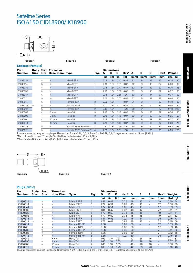
81
PNEU
MAT
ICSP
ECIA
L A
PPLI
CATI
ON
SD
IAG
NO
STIC
AG
RICU
LTU
RERE
FRIG
ERA
NT
FLU
ID T
RAN
SFER
AN
D H
YDRA
ULI
C
EATON Quick Disconnect Couplings EMEA E-MEQD-CC002-E4 December 2018
Safeline SeriesISO 6150 C ID18900/IK18900
Figure 1 Figure 2 Figure 3 Figure 4
Sockets (Female)Part Body Port Thread or DimensionsNumber Size Size Hose Diam. Type Fig. A B C Hex1 A B C Hex1 Weight
(in) (in) (in) (in) (mm) (mm) (mm) (mm) (lbs) (g)ID1896015 ¼ ¼ Male BSPP 1 2.45 1.34 0.47 0.87 62 34 12 22 0.35 160
ID1896014 ¼ ¼ Male BSPT 1 2.45 1.34 0.51 0.87 62 34 13 22 0.36 162
ID1896039 Male BSPP 1 2.45 1.34 0.47 0.87 62 34 12 22 0.36 165
ID1896038 Male BSPT 1 2.45 1.34 0.59 0.87 62 34 15 22 0.37 168
ID1896013 ½ ½ Male BSPP 1 2.45 1.34 0.55 1.06 62 34 14 27 0.37 168
ID1896012 ½ ½ Male BSPT 1 2.45 1.34 0.67 0.87 62 34 17 22 0.40 180
ID1897014 ¼ ¼ Female BSPP 2 2.92 1.34 – 0.87 74 34 – 22 0.40 182
ID1897038 Female BSPP 2 3.02 1.34 – 0.87 77 34 – 22 0.40 180ID1897012 ½ ½ Female BSPP 2 3.16 1.34 – 1.06 80 34 – 27 0.48 216ID1895689 – 8 mm Hose Tail 3 2.49 1.34 1.10 0.87 63 34 28 22 0.36 165
ID1895690 – 9 mm Hose Tail 3 2.49 1.34 1.10 0.87 63 34 28 22 0.35 160
ID1895601 – 10 mm Hose Tail 3 2.49 1.34 1.10 0.87 63 34 28 22 0.37 166
ID1895613 – 13 mm Hose Tail 3 2.49 1.34 1.30 0.87 63 34 33 22 0.39 177
ID1895038 Female BSPP, Bulkhead* 4 2.37 1.34 0.79 1.26 60 34 20 32 0.52 235
ID1895012 ½ Female BSPP, Bulkhead** 4 2.39 1.34 0.91 1.38 61 34 23 35 0.59 269To obtain connected length of coupling add Dimensions A or A+C (Fig. 1, 2, 3, 4) and D or D+E (Fig. 5, 6, 7) together and substract 40 mm (1,57 in). *Max bulkhead thickness: 12 mm (0,47 in) / Bulkhead hole diameter = 25 mm (0,98 in) **Max bulkhead thickness: 15 mm (0,59 in) / Bulkhead hole diameter = 31 mm (1,22 in)
Figure 5 Figure 6 Figure 7
Plugs (Male)Part Body Port Thread or DimensionsNumber Size Size Hose Diam. Type Fig. D E F Hex1 D E F Hex1 Weight
(in) (in) (in) (in) (mm) (mm) (mm) (mm) (lbs) (g)IK1890615 ¼ ¼ Male BSPP 5 1.81 0.47 0.75 46 12 – 19 0.10 44IK1890614 ¼ ¼ Male BSPT 5 1.77 0.51 0.67 45 13 – 17 0.08 38IK1890641 ¼ ¼ Male NPT 5 1.77 0.51 0.67 45 13 – 17 0.09 39IK1890639 Male BSPP 5 1.81 0.47 0.87 46 12 – 22 0.11 51IK1890638 Male BSPT 5 1.77 0.59 0.75 45 15 – 19 0.11 51IK1890683 Male NPT 5 1.77 0.59 0.75 45 15 – 19 0.11 52IK1890613 ½ ½ Male BSPP 5 1.81 0.55 1.02 46 14 – 26 0.16 73IK1890612 ½ ½ Male BSPT 5 1.77 0.67 0.87 45 17 – 22 0.15 66IK1890714 ¼ ¼ Female BSPP 6 2.36 0.67 60 – – 17 0.09 40IK1890741 ¼ ¼ Female NPT 6 2.36 0.67 60 – – 17 0.09 40IK1890738 Female BSPP 6 2.36 0.83 60 – – 21 0.11 52IK1890783 Female NPT 6 2.36 0.83 60 – – 21 0.12 55IK1890712 ½ ½ Female BSPP 6 2.36 1.02 60 – – 26 0.15 66IK1890989 – 8 mm Hose Tail 7 1.65 1.10 0.63 42 28 16 – 0.07 33IK1890990 – 9 mm Hose Tail 7 1.65 1.10 0.63 42 28 16 – 0.07 33IK1890901 – 10 mm Hose Tail 7 1.65 1.10 0.63 42 28 16 – 0.08 35IK1890913 – 13 mm Hose Tail 7 1.65 1.30 0.79 42 33 20 – 0.10 46To obtain connected length of coupling add Dimensions A or A+C (Fig. 1, 2, 3, 4) and D or D+E (Fig. 5, 6, 7) together and substract 40 mm (1,57 in).

82
FLUID
TRAN
SFERA
ND
HYD
RAU
LICPN
EUM
ATICSPECIA
L APPLICATIO
NS
DIA
GN
OSTIC
AG
RICULTU
REREFRIG
ERAN
T
EATON Quick Disconnect Couplings EMEA E-MEQD-CC002-E4 December 2018
Eaton's Safeline Series is an Industrial Interchange pneumatic coupling with push button safety feature designed for use with compressed air. Two-step disconnect procedure shuts off air supply and releases downstream air pressure before plug can be removed from socket/female, which prevents hose whip.
• Safe and easy to connect and disconnect
• Light weight, compact ergonomic design
• Meets Safety Standard ISO 4414
• Meets ISO 6150 Series C Standard
• Standard body material: Dural
• Standard seal material: Buna-N
Product Features
Safeline SeriesISO 6150 C TD18300/TK18300
Applications & Markets• General Pneumatics • Air Tools • Industrial Plants • Maintenance and Repair
Flow Data
Physical Characteristics Body Nominal Flow Max. Operating Pressure Air Flow Rate* Working Size Diameter Connected or Disconnected ∆p 0.6 bar/8.7 psi** ∆p 1 bar/14.5 psi*** Temperature
(mm) (bar) (psi) (lpm) (gpm) (lpm) (gpm) °C °F
½ 11 16 232 2,400 634 3,000 793 -20° +100° -4° +212°
*Indicated values refer to an inlet pressure of 6 bar / 87 psi. **This flow rate allows the optimum output from a pneumatic tool. ** This flow rate is the maximum recommended for a suitable output from a pneumatic tool. For applications needing higher flow rates, it is recommended to select a larger
size coupling.
Air flow-rate at 6 bar (87 psi)
04624624.621.45
14.5
0.1
1
000010001001
Flow rate (gpm)
Pres
sure
dro
p (P
SI)
Pres
sure
dro
p (b
ar)
Flow rate (l/min)
29,0
2,90
4,35
7,25
0,2
0,3
0,5

83
PNEU
MAT
ICSP
ECIA
L A
PPLI
CATI
ON
SD
IAG
NO
STIC
AG
RICU
LTU
RERE
FRIG
ERA
NT
FLU
ID T
RAN
SFER
AN
D H
YDRA
ULI
C
EATON Quick Disconnect Couplings EMEA E-MEQD-CC002-E4 December 2018
Safeline SeriesISO 6150 C TD18300/TK18300
Figure 1 Figure 2 Figure 3 Figure 4
Sockets (Female)Part Body Port Thread or DimensionsNumber Size Size Hose Diam. Type Fig. A B C Hex1 Hex2 A B C Hex1 Hex2 Weight
(in) (in) (in) (in) (in) (mm) (mm) (mm) (mm) (mm) (lbs) (g)
TD1832012 ½ ½ Male BSPT 1 2.78 1.56 0.67 1.06 70.6 39.5 17 27 0.58 262
TD1832034 ¾ ¾ Male BSPT 1 2.78 1.56 0.73 1.14 70.6 39.5 19 29 0.63 287
TD1832138 Female BSPP 2 3.27 1.56 1.06 83.1 39.5 - 27 0.62 280
TD1832112 ½ ½ Female BSPP 2 3.27 1.56 1.06 83.1 39.5 - 27 0.58 261
TD1832134 ½ ¾ ¾ Female BSPP 2 3.51 1.56 1.26 89.1 39.5 - 32 0.67 304
TD1835601 - 10 mm Hose Tail 3 2.84 1.56 1.10 1.06 72.1 39.5 28 27 0.56 256
TD1835613 - 13 mm Hose Tail 3 2.84 1.56 1.30 1.06 72.1 39.5 33 27 0.59 267
TD1835616 - 16 mm Hose Tail 3 2.84 1.56 1.30 1.06 72.1 39.5 33 27 0.60 270
TD1835012 ½ ½ Female BSPP, Bulkhead* 4 2.78 1.56 0.91 1.38 70.6 39.5 23 35 0.76 343
TD1835034 ¾ ¾ Female BSPP, Bulkhead** 4 2.82 1.56 0.98 1.50 71.6 39.5 25 38 0.77 350To obtain connected length of coupling add Dimensions A or A+C (Fig. 1, 2, 3, 4) and D or D+E (Fig. 5, 6, 7) together and substract 20 mm (0,79 in). *Max bulkhead thickness: 15 mm (0,59 in) / Bulkhead hole diameter = 31 mm (1,22 in) **Max bulkhead thickness: 16 mm (0,63 in) / Bulkhead hole diameter = 33 mm (1,30 in)
Plugs (Male)Part Body Port Thread or DimensionsNumber Size Size Hose Diam. Type Fig. D E F Hex1 D E F Hex1 Weight
(in) (in) (in) (in) (mm) (mm) (mm) (mm) (lbs) (g)TK1831539 Male BSPP 5 2.01 0.47 0.87 51.1 11.9 22 2.32 59TK1831512 ½ ½ Male BSPT 5 1.97 0.67 0.87 50 17 22 2.56 65TK1831534 ¾ ¾ Male BSPT 5 2.11 0.73 1.14 53.5 18.5 29 3.86 98TK1831638 Female BSPP 6 2.56 1.02 65 26 3.70 94TK1831612 ½ ½ ½ Female BSPP 6 2.56 1.02 65 26 3.02 77TK1831634 ¾ ¾ Female BSPP 6 2.87 1.26 73 32 5.02 128TK1831889 - 8 mm Hose Tail 7 1.85 1.10 0.79 47 28 20 1.87 48TK1831801 - 10 mm Hose Tail 7 1.85 1.10 0.79 47 28 20 1.91 48TK1831813 - 13 mm Hose Tail 7 1.85 1.30 0.79 47 33 20 2.19 56TK1831816 - 16 mm Hose Tail 7 1.85 1.30 0.79 47 33 20 2.40 61To obtain connected length of coupling add Dimensions A or A+C (Fig. 1, 2, 3, 4) and D or D+E (Fig. 5, 6, 7) together and substract 20 mm (0,79 in).
Figure 5 Figure 6 Figure 7
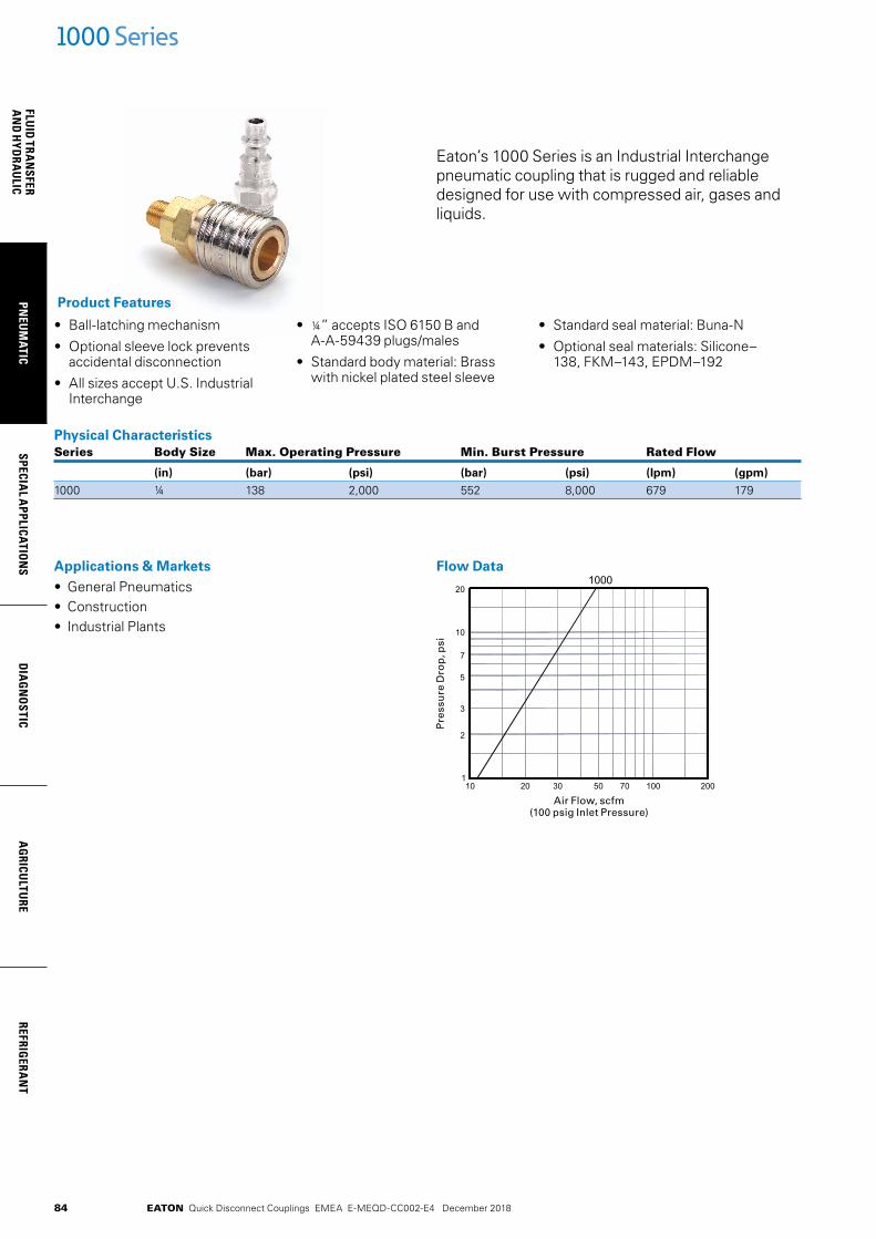
84
FLUID
TRAN
SFERA
ND
HYD
RAU
LICPN
EUM
ATICSPECIA
L APPLICATIO
NS
DIA
GN
OSTIC
AG
RICULTU
REREFRIG
ERAN
T
EATON Quick Disconnect Couplings EMEA E-MEQD-CC002-E4 December 2018
Eaton’s 1000 Series is an Industrial Interchange pneumatic coupling that is rugged and reliable designed for use with compressed air, gases and liquids.
• Ball-latching mechanism
• Optional sleeve lock prevents accidental disconnection
• All sizes accept U.S. Industrial Interchange
• ¼” accepts ISO 6150 B and A-A-59439 plugs/males
• Standard body material: Brass with nickel plated steel sleeve
• Standard seal material: Buna-N
• Optional seal materials: Silicone–138, FKM–143, EPDM–192
Product Features
Physical Characteristics Series Body Size Max. Operating Pressure Min. Burst Pressure Rated Flow
(in) (bar) (psi) (bar) (psi) (lpm) (gpm)
1000 ¼ 138 2,000 552 8,000 679 179
1000 Series
Applications & Markets• General Pneumatics• Construction• Industrial Plants
Flow Data
Pre
ssu
re D
rop
, psi
Air Flow, scfm(100 psig Inlet Pressure)

85
PNEU
MAT
ICSP
ECIA
L A
PPLI
CATI
ON
SD
IAG
NO
STIC
AG
RICU
LTU
RERE
FRIG
ERA
NT
FLU
ID T
RAN
SFER
AN
D H
YDRA
ULI
C
EATON Quick Disconnect Couplings EMEA E-MEQD-CC002-E4 December 2018
A
B
C
D
HEXHEX
1000 Series
Figure 1 Figure 2
Male NPTF ConnectionsPart Coupling Body Port Dimensions Number Type Size Size Thread Type Material Fig. A B Hex A B Hex
(in) (in) (in) (mm) (mm) (mm)
900 Socket/Female ¼ -27 NPTF Brass 1 1.97 1.00 0.69 50.04 25.40 17.53 1100 Socket/Female ¼ ¼ ¼-18 NPTF Brass 1 2.16 1.00 0.69 54.86 25.40 17.53 1300 Socket/Female ¼ -18 NPTF Brass 1 2.12 1.00 0.69 53.85 25.40 17.53 LL1100 Socket/Female ¼ ¼ ¼-18 NPTF Stainless 1 2.16 1.00 0.69 54.86 25.40 17.53Part Coupling Body Port Dimensions Number Type Size Size Thread Type Material Fig. C D Hex C D Hex
(in) (in) (in) (mm) (mm) (mm)
10 Plug/Male ¼ ¼ ¼-18 NPTF Steel 2 1.75 0.62 0.56 44.45 15.75 14.22 10C§ Plug/Male ¼ ¼ ¼-18 NPTF Steel 2 1.75 0.65 0.56 44.45 16.51 14.22 10G† Plug/Male ¼ ¼ ¼-18 NPTF Steel 2 1.75 0.65 0.56 44.45 16.51 14.22 12E Plug/Male ¼ -27 NPTF Steel 2 1.59 0.58 0.50 40.38 14.73 12.712G† Plug/Male ¼ -27 NPTF Steel 2 2.38 0.77 0.69 60.45 19.55 17.5214 Plug/Male ¼ -18 NPTF Steel 2 1.75 0.79 0.69 44.45 20.06 17.52 14G† Plug/Male ¼ -18 NPTF Steel 2 2.53 0.77 0.69 64.26 19.55 17.52 B10 Plug/Male ¼ ¼ ¼-18 NPTF Brass 2 1.75 0.62 0.56 44.45 16.25 14.22 LL10 Plug/Male ¼ ¼ ¼-18 NPTF Stainless 2 1.75 0.62 0.56 44.45 16.51 14.22 10NK* Plug/Male ¼ ¼ ¼-18 NPTF Steel 2 1.75 0.62 0.56 44.45 15.75 14.22
§ With Ball Check †With Bleeder Ball Check—Reduces Hose Whip *Nickel plated
Female NPTF ConnectionsPart Coupling Body Port Dimensions Number Type Size Size Thread Type Material Fig. A B Hex A B Hex
(in) (in) (in) (mm) (mm) (mm)
800E Socket/Female ¼ -27 NPTF Brass 3 1.86 1.00 0.69 47.24 25.40 17.53 1000E Socket/Female ¼ ¼ ¼-18 NPTF Brass 3 2.08 1.00 0.69 52.83 25.40 17.53 1200 Socket/Female ¼ -18 NPTF Brass 3 2.16 1.00 0.75 54.86 25.40 19.05 LL1000 Socket/Female ¼ ¼ ¼-18 NPTF Stainless 3 2.08 1.00 0.69 52.83 25.40 17.53Part Coupling Body Port Dimensions Number Type Size Size Thread Type Material Fig. C D Hex C D Hex
(in) (in) (in) (mm) (mm) (mm)
11 Plug/Male ¼ ¼ ¼-18 NPTF Steel 4 1.63 0.79 0.69 41.40 20.07 17.53 11G† Plug/Male ¼ ¼ ¼-18 NPTF Steel 4 2.44 0.77 0.69 61.98 19.56 17.53 13 Plug/Male ¼ -27 NPTF Steel 4 1.47 0.65 0.56 37.34 16.51 14.22 15E Plug/Male ¼ -18 NPTF Steel 4 1.69 0.94 0.81 42.93 23.88 20.57 11B Plug/Male ¼ ¼ ¼-18 NPTF Brass 4 1.63 0.78 0.69 41.40 19.81 17.53 LL11 Plug/Male ¼ ¼ ¼-18 NPTF Stainless 4 1.63 0.79 0.69 41.40 20.07 17.53 11NK* Plug/Male ¼ ¼ ¼-18 NPTF Steel 4 1.63 0.79 0.69 41.40 20.07 17.53
†With Bleeder Ball Check—Reduces Hose Whip *Nickel plated
A
B
C
D
HEXHEX
Figure 3 Figure 4
C
DB
A
HEXHEX
C
DB
A
HEXHEX
86
FLUID
TRAN
SFERA
ND
HYD
RAU
LICPN
EUM
ATICSPECIA
L APPLICATIO
NS
DIA
GN
OSTIC
AG
RICULTU
REREFRIG
ERAN
T
EATON Quick Disconnect Couplings EMEA E-MEQD-CC002-E4 December 2018
C
D
A
B
1000 Series
Figure 5 Figure 6
Hose Stem End Connections Part Coupling Body Hose Dimensions Number Type Size I.D. Material Fig. A B A B
(in) (in) (mm) (mm)
1600E Socket/Female ¼ ¼ Brass 5 2.60 1.00 66.04 25.40 1600P‡ Socket/Female ¼ ¼ Brass 5, 5A 2.37 1.00 60.20 25.40 1700E Socket/Female ¼ Brass 5 2.60 1.00 66.04 25.40 1700P‡ Socket/Female ¼ Brass 5, 5A 2.44 1.00 61.98 25.40 1800 Socket/Female ¼ Brass 5 2.60 1.00 66.04 25.40Part Coupling Body Hose Dimensions Number Type Size I.D. Material Fig. C D C D
(in) (in) (mm) (mm)
16 Plug/Male ¼ ¼ Steel 6 2.22 0.50 56.39 12.70 16G† Plug/Male ¼ ¼ Steel 6 2.97 0.77 75.44 19.56 16P‡ Plug/Male ¼ ¼ Steel 6, 6A 2.00 0.58 50.80 14.73 17 Plug/Male ¼ Steel 6 2.22 0.5 56.39 12.70 17G‡ Plug/Male ¼ Steel 6 2.96 0.77 75.18 19.56 17P‡ Plug/Male ¼ Steel 6, 6A 2.06 0.5 52.32 12.70 18E Plug/Male ¼ Steel 6 2.22 0.50 56.39 12.70 B17 Plug/Male ¼ Brass 6 2.22 0.5 56.39 12.70 16NK* Plug/Male ¼ ¼ Steel 6 2.22 0.50 56.39 12.70 17NK* Plug/Male ¼ Steel 6 2.22 0.5 56.39 12.70
†With Bleeder Ball Check—Reduces Hose Whip ‡ For use with push-on style hose *Nickel plated
1600P 1700P 16P 17P
Figure 5A Figure 6A
1600P 1700P 16P 17P

87
PNEU
MAT
ICSP
ECIA
L A
PPLI
CATI
ON
SD
IAG
NO
STIC
AG
RICU
LTU
RERE
FRIG
ERA
NT
FLU
ID T
RAN
SFER
AN
D H
YDRA
ULI
C
EATON Quick Disconnect Couplings EMEA E-MEQD-CC002-E4 December 2018
D
CA
B
HEXHEX
1000 Series
Figure 7 Figure 8
Hose Clamp End Connections Part Coupling Body Hose Hose Dimensions Number Type Size I.D. O.D. Material Fig. A B Hex A B Hex
(in) (in) (in) (mm) (mm) (mm)
1SB1 Socket/Female ¼ ¼ 15/32 Brass 7 2.69 1.00 0.69 68.33 25.40 17.53 1SB3 Socket/Female ¼ ¼ ½ Brass 7 2.69 1.00 0.69 68.33 25.40 17.53 1SB5E Socket/Female ¼ ¼ Brass 7 2.69 1.00 0.69 68.33 25.40 17.53 1SB7 Socket/Female ¼ ¼ 5/8 Brass 7 2.69 1.00 0.69 68.33 25.40 17.53 1SC5 Socket/Female ¼ Brass 7 2.75 1.00 0.69 69.85 25.40 17.53 1SC7 Socket/Female ¼ 5/8 Brass 7 2.75 1.00 0.69 69.85 25.40 17.53 1SC9 Socket/Female ¼ 11/16 Brass 7 2.75 1.00 0.69 69.85 25.40 17.53 1SD5 Socket/Female ¼ Brass 7 2.81 1.00 0.69 71.37 25.40 17.53 1SD7 Socket/Female ¼ 5/8 Brass 7 2.81 1.00 0.69 71.37 25.40 17.53 1SD9 Socket/Female ¼ 11/16 Brass 7 2.81 1.00 0.69 71.37 25.40 17.53 1SD11 Socket/Female ¼ ¾ Brass 7 2.81 1.00 0.69 71.37 25.40 17.53Part Coupling Body Hose Hose Dimensions Number Type Size I.D. O.D. Material Fig. C D Hex C D Hex
(in) (in) (in) (mm) (mm) (mm)
3PB1 Plug/Male ¼ ¼ 15/32 Steel 8 2.31 0.70 0.63 58.67 17.78 16.00 3PB3 Plug/Male ¼ ¼ ½ Steel 8 2.31 0.70 0.63 58.67 17.78 16.00 3PB5 Plug/Male ¼ ¼ Steel 8 2.31 0.77 0.69 58.67 19.56 17.53 3PB7 Plug/Male ¼ ¼ 5/8 Steel 8 2.31 0.84 0.75 58.67 21.34 19.05 3PB9 Plug/Male ¼ ¼ 11/16 Steel 8 2.31 0.94 0.81 58.67 23.88 20.57 3PB11 Plug/Male ¼ ¼ ¾ Steel 8 2.31 0.98 0.88 58.67 24.89 22.35 3PC5 Plug/Male ¼ Steel 8 2.38 0.77 0.69 60.45 19.56 17.53 3PC7 Plug/Male ¼ 5/8 Steel 8 2.38 0.84 0.75 60.45 21.34 19.05 3PC9 Plug/Male ¼ 11/16 Steel 8 2.38 0.91 0.81 60.45 23.11 20.57 3PD5 Plug/Male ¼ Steel 8 2.44 0.77 0.69 61.98 19.56 17.53 3PD7 Plug/Male ¼ 5/8 Steel 8 2.44 0.84 0.75 61.98 21.34 19.05 3PD9 Plug/Male ¼ 11/16 Steel 8 2.44 0.91 0.81 61.98 23.11 20.57 3PD11 Plug/Male ¼ ¾ Steel 8 2.44 1.01 0.88 61.98 25.65 22.35
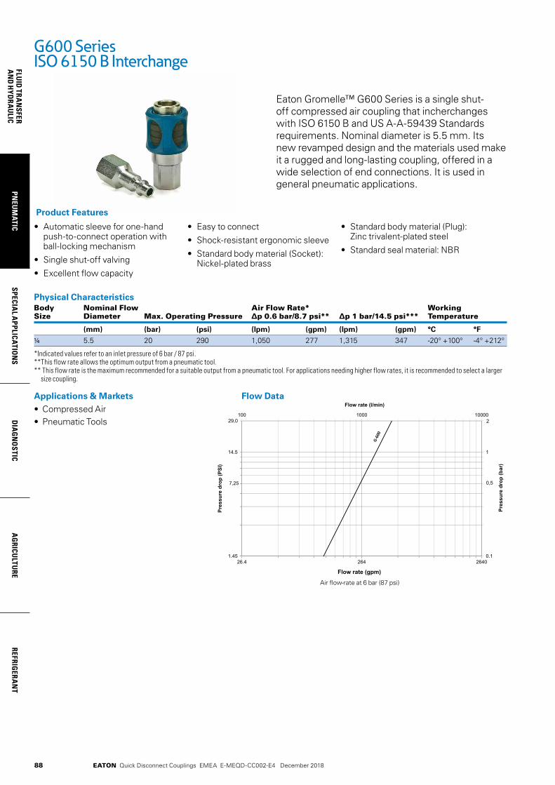
88
FLUID
TRAN
SFERA
ND
HYD
RAU
LICPN
EUM
ATICSPECIA
L APPLICATIO
NS
DIA
GN
OSTIC
AG
RICULTU
REREFRIG
ERAN
T
EATON Quick Disconnect Couplings EMEA E-MEQD-CC002-E4 December 2018
Eaton Gromelle™ G600 Series is a single shut- off compressed air coupling that incherchanges with ISO 6150 B and US A-A-59439 Standards requirements. Nominal diameter is 5.5 mm. Its new revamped design and the materials used make it a rugged and long-lasting coupling, offered in a wide selection of end connections. It is used in general pneumatic applications.
• Automatic sleeve for one-hand push-to-connect operation with ball-locking mechanism
• Single shut-off valving
• Excellent flow capacity
• Easy to connect
• Shock-resistant ergonomic sleeve
• Standard body material (Socket): Nickel-plated brass
• Standard body material (Plug): Zinc trivalent-plated steel
• Standard seal material: NBR
Product Features
Physical Characteristics Body Nominal Flow Air Flow Rate* Working Size Diameter Max. Operating Pressure ∆p 0.6 bar/8.7 psi** ∆p 1 bar/14.5 psi*** Temperature
(mm) (bar) (psi) (lpm) (gpm) (lpm) (gpm) °C °F
1/4 5.5 20 290 1,050 277 1,315 347 -20° +100° -4° +212°
*Indicated values refer to an inlet pressure of 6 bar / 87 psi. **This flow rate allows the optimum output from a pneumatic tool. ** This flow rate is the maximum recommended for a suitable output from a pneumatic tool. For applications needing higher flow rates, it is recommended to select a larger
size coupling.
G600 Series ISO 6150 B Interchange
Applications & Markets• Compressed Air • Pneumatic Tools
Flow Data
Air flow-rate at 6 bar (87 psi)
04624624.621.45
14.5
0.1
1
000010001001
Flow rate (gpm)
Pres
sure
dro
p (P
SI)
Pres
sure
dro
p (b
ar)
Flow rate (l/min)
Hydraulic Oil viscosity : 30 Cst at 40°C / 104°F
29,0
7,25
2
0,5
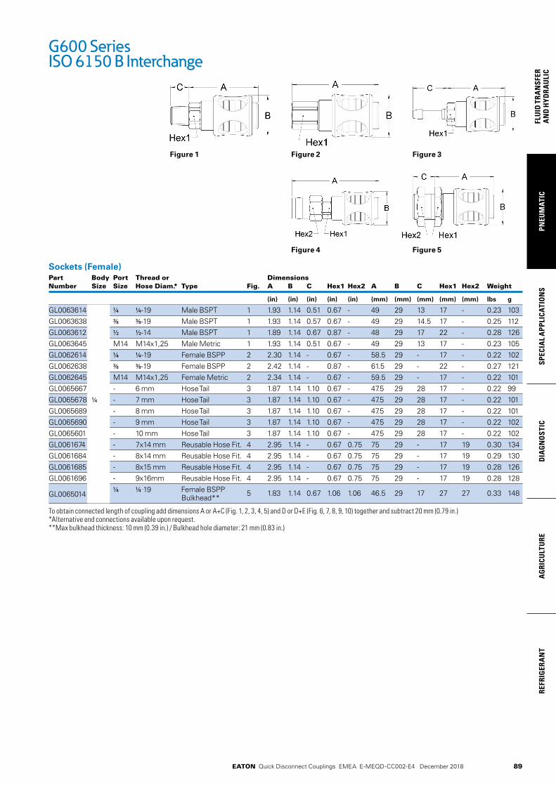
89
PNEU
MAT
ICSP
ECIA
L A
PPLI
CATI
ON
SD
IAG
NO
STIC
AG
RICU
LTU
RERE
FRIG
ERA
NT
FLU
ID T
RAN
SFER
AN
D H
YDRA
ULI
C
EATON Quick Disconnect Couplings EMEA E-MEQD-CC002-E4 December 2018
Figure 1
Sockets (Female)Part Body Port Thread or Dimensions Number Size Size Hose Diam.* Type Fig. A B C Hex1 Hex2 A B C Hex1 Hex2 Weight
(in) (in) (in) (in) (in) (mm) (mm) (mm) (mm) (mm) lbs g
GL0063614 1/4 1/4-19 Male BSPT 1 1.93 1.14 0.51 0.67 - 49 29 13 17 - 0.23 103GL0063638 3/8 3/8-19 Male BSPT 1 1.93 1.14 0.57 0.67 - 49 29 14.5 17 - 0.25 112GL0063612 1/2 1/2-14 Male BSPT 1 1.89 1.14 0.67 0.87 - 48 29 17 22 - 0.28 126GL0063645 M14 M14x1,25 Male Metric 1 1.93 1.14 0.51 0.67 - 49 29 13 17 - 0.23 105GL0062614 1/4 1/4-19 Female BSPP 2 2.30 1.14 - 0.67 - 58.5 29 - 17 - 0.22 102GL0062638 3/8 3/8-19 Female BSPP 2 2.42 1.14 - 0.87 - 61.5 29 - 22 - 0.27 121GL0062645 M14 M14x1,25 Female Metric 2 2.34 1.14 - 0.67 - 59.5 29 - 17 - 0.22 101GL0065667 - 6 mm Hose Tail 3 1.87 1.14 1.10 0.67 - 47.5 29 28 17 - 0.22 99GL0065678 1/4 - 7 mm Hose Tail 3 1.87 1.14 1.10 0.67 - 47.5 29 28 17 - 0.22 101GL0065689 - 8 mm Hose Tail 3 1.87 1.14 1.10 0.67 - 47.5 29 28 17 - 0.22 101GL0065690 - 9 mm Hose Tail 3 1.87 1.14 1.10 0.67 - 47.5 29 28 17 - 0.22 102GL0065601 - 10 mm Hose Tail 3 1.87 1.14 1.10 0.67 - 47.5 29 28 17 - 0.22 102GL0061674 - 7x14 mm Reusable Hose Fit. 4 2.95 1.14 - 0.67 0.75 75 29 - 17 19 0.30 134GL0061684 - 8x14 mm Reusable Hose Fit. 4 2.95 1.14 - 0.67 0.75 75 29 - 17 19 0.29 130GL0061685 - 8x15 mm Reusable Hose Fit. 4 2.95 1.14 - 0.67 0.75 75 29 - 17 19 0.28 126GL0061696 - 9x16mm Reusable Hose Fit. 4 2.95 1.14 - 0.67 0.75 75 29 - 17 19 0.28 128
GL0065014 1/4 1/4 -19 Female BSPP
Bulkhead** 5 1.83 1.14 0.67 1.06 1.06 46.5 29 17 27 27 0.33 148
To obtain connected length of coupling add dimensions A or A+C (Fig. 1, 2, 3, 4, 5) and D or D+E (Fig. 6, 7, 8, 9, 10) together and subtract 20 mm (0.79 in.) *Alternative end connections available upon request. **Max bulkhead thickness: 10 mm (0.39 in.) / Bulkhead hole diameter: 21 mm (0.83 in.)
G600 Series ISO 6150 B Interchange
Figure 2 Figure 3
Figure 4 Figure 5

90
FLUID
TRAN
SFERA
ND
HYD
RAU
LICPN
EUM
ATICSPECIA
L APPLICATIO
NS
DIA
GN
OSTIC
AG
RICULTU
REREFRIG
ERAN
T
EATON Quick Disconnect Couplings EMEA E-MEQD-CC002-E4 December 2018
Figure 6
Plug (Male)Part Body Port Thread or Dimensions Number Size Size Hose Diam.* Type Fig. D E F Hex1 Hex2 D E F Hex1 Hex2 Weight
(in) (in) (in) (in) (in) (mm) (mm) (mm) (mm) (mm) lbs g
GA0066318 1/8 1/8-28 Male BSPT 6 1.26 0.35 - 0.47 - 32 9 - 12 - 0.04 19
GA0066314 1/4 1/4-19 Male BSPT 6 1.26 0.51 - 0.55 - 32 13 - 14 - 0.06 25
10 1/4 1/4-18 Male NPT 6 1.22 0.55 - 0.59 - 31 14 - 15 - 0.06 25
GA0066338 3/8 3/8-19 Male BSPT 6 1.26 0.59 - 0.67 - 32 15 - 17 - 0.08 38
GA0066345 M14 M14x1,25 Male Metric 6 1.26 0.51 - 0.55 - 32 13 - 14 - 0.06 26
GA0066214 1/4 1/4-19 Female BSPP 7 1.73 - - 0.67 - 44 - - 17 - 0.07 30
11 1/4 1/4-18 Female NPT 7 1.63 - - 0.71 - 41.5 - - 18 - 0.07 30
GA0066238 3/8 3/8-19 Female BSPP 7 1.73 - - 0.83 - 44 - - 21 - 0.08 37
GA0066245 M14 M14x1,25 Female Metric 7 1.73 - - 0.67 - 44 - - 17 - 0.06 25
GA0066248 1/4 - M14x1,25 Female Metric 7 1.73 - - 0.55 - 44 - - 14 - 0.05 24
GA0066767 - 6 mm Hose Tail 8 1.10 1.02 0.55 - - 28 26 14 - - 0.04 19
GA0066778 - 7 mm Hose Tail 8 1.10 1.02 0.55 - - 28 26 14 - - 0.04 20
GA0066789 - 8 mm Hose Tail 8 1.10 1.02 0.55 - - 28 26 14 - - 0.04 20
GA0066790 - 9 mm Hose Tail 8 1.10 1.02 0.55 - - 28 26 14 - - 0.04 20
GA0066701 - 10 mm Hose Tail 8 1.10 1.02 0.55 - - 28 26 14 - - 0.05 22
GA0066174 - 7x14 mm Reusable Hose Fit. 9 2.22 - - 0.63 0.75 56.5 - - 16 19 0.12 56
GA0066184 - 8x14 mm Reusable Hose Fit. 9 2.22 - - 0.63 0.75 56.5 - - 16 19 0.13 57
GA0066185 - 8x15 mm Reusable Hose Fit. 9 2.22 - - 0.63 0.75 56.5 - - 16 19 0.12 53
GA0066196 - 9x16 mm Reusable Hose Fit. 9 2.22 - - 0.63 0.75 56.5 - - 16 19 0.11 51
GA0066814 1/4 1/4-19 Female BSPP Swivel 10 1.50 - - 0.67 - 38 - - 17 - 0.06 26
GA0066845 M14 M14x1,25 Female Metric Swivel 10 1.50 - - 0.67 - 38 - - 17 - 0.06 26
To obtain connected length of coupling add dimensions A or A+C (Fig. 1, 2, 3, 4, 5) and D or D+E (Fig. 6, 7, 8, 9, 10) together and subtract 20 mm (0.79 in.) *Alternative end connections available upon request.
G600 Series ISO 6150 B Interchange
Figure 7 Figure 8
Figure 9 Figure 10
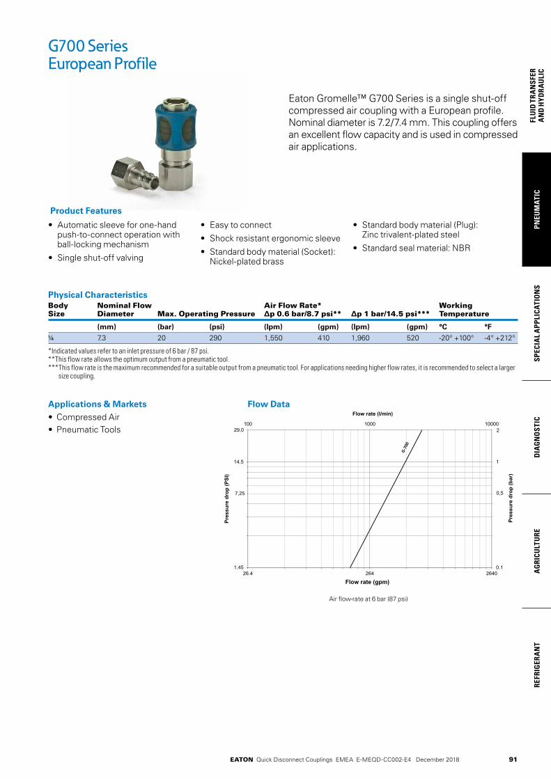
91
PNEU
MAT
ICSP
ECIA
L A
PPLI
CATI
ON
SD
IAG
NO
STIC
AG
RICU
LTU
RERE
FRIG
ERA
NT
FLU
ID T
RAN
SFER
AN
D H
YDRA
ULI
C
EATON Quick Disconnect Couplings EMEA E-MEQD-CC002-E4 December 2018
Eaton Gromelle™ G700 Series is a single shut-off compressed air coupling with a European profile. Nominal diameter is 7.2/7.4 mm. This coupling offers an excellent flow capacity and is used in compressed air applications.
• Automatic sleeve for one-hand push-to-connect operation with ball-locking mechanism
• Single shut-off valving
• Easy to connect
• Shock resistant ergonomic sleeve
• Standard body material (Socket): Nickel-plated brass
• Standard body material (Plug): Zinc trivalent-plated steel
• Standard seal material: NBR
Product Features
Physical Characteristics Body Nominal Flow Air Flow Rate* Working Size Diameter Max. Operating Pressure ∆p 0.6 bar/8.7 psi** ∆p 1 bar/14.5 psi*** Temperature
(mm) (bar) (psi) (lpm) (gpm) (lpm) (gpm) °C °F
1/4 7.3 20 290 1,550 410 1,960 520 -20° +100° -4° +212°
*Indicated values refer to an inlet pressure of 6 bar / 87 psi. **This flow rate allows the optimum output from a pneumatic tool. *** This flow rate is the maximum recommended for a suitable output from a pneumatic tool. For applications needing higher flow rates, it is recommended to select a larger
size coupling.
G700 Series European Profile
Applications & Markets• Compressed Air • Pneumatic Tools
Flow Data
Air flow-rate at 6 bar (87 psi)
04624624.621.45
14.5
0.1
1
000010001001
Flow rate (gpm)
Pres
sure
dro
p (P
SI)
Pres
sure
dro
p (b
ar)
Flow rate (l/min)
29,0
7,25
2
0,5
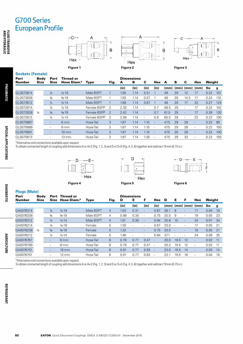
92
FLUID
TRAN
SFERA
ND
HYD
RAU
LICPN
EUM
ATICSPECIA
L APPLICATIO
NS
DIA
GN
OSTIC
AG
RICULTU
REREFRIG
ERAN
T
EATON Quick Disconnect Couplings EMEA E-MEQD-CC002-E4 December 2018
Figure 1
Sockets (Female)Part Body Port Thread or Dimensions Number Size Size Hose Diam.* Type Fig. A B C Hex A B C Hex Weight
(in) (in) (in) (in) (mm) (mm) (mm) (mm) lbs g
GL0073614 1/4 1/4-19 Male BSPT 1 1.93 1.14 0.51 1 49 29 13 17 0.22 101GL0073638 3/8 3/8-19 Male BSPT 1 1.93 1.14 0.57 1 49 29 14.5 17 0.24 110GL0073612 1/2 1/2-14 Male BSPT 1 1.89 1.14 0.67 1 48 29 17 22 0.27 124GL0072614 1/4 1/4-19 Female BSPP 2 2.30 1.14 - 0.7 58.5 29 - 17 0.22 102GL0072638 1/4 3/8 3/8-19 Female BSPP 2 2.42 1.14 - 0.7 61.5 29 - 17 0.26 120GL0072612 1/2 1/2-14 Female BSPP 2 2.58 1.14 - 0.9 65.5 29 - 22 0.22 100GL0075667 - 6 mm Hose Tail 3 1.87 1.14 1.10 - 47.5 29 28 - 0.22 98GL0075689 - 8 mm Hose Tail 3 1.87 1.14 1.10 - 47.5 29 28 - 0.22 100GL0075601 - 10 mm Hose Tail 3 1.87 1.14 1.10 - 47.5 29 28 - 0.22 100GL0075613 - 13 mm Hose Tail 3 1.87 1.14 1.30 - 47.5 29 33 - 0.22 100
*Alternative end connections available upon request. To obtain connected length of coupling add dimensions A or A+C (Fig. 1, 2, 3) and D or D+E (Fig. 4, 5, 6) together and subtract 19 mm (0.75 in.).
Plugs (Male)Part Body Port Thread or Dimensions Number Size Size Hose Diam.* Type Fig. D E F Hex D E F Hex Weight
(in) (in) (in) (in) (mm) (mm) (mm) (mm) lbs g
GA0076314 1/4 1/4-19 Male BSPT 4 1.03 0.31 - 0.67 26.1 8 - 17 0.04 19GA0076338 3/8 3/8-19 Male BSPT 4 0.99 0.35 - 0.75 25.0 9 - 19 0.05 23GA0076312 1/2 1/2-14 Male BSPT 4 1.01 0.39 - 0.94 25.6 10 - 24 0.07 34GA0076214 1/4 1/4-19 Female 5 1.30 - - 0.67 33.0 - - 17 0.05 21GA0076238 1/4 3/8 3/8-19 Female 5 1.32 - - 0.75 33.5 - - 19 0.05 21GA0076212 1/2 1/2-14 Female 5 1.46 - - 0.94 37.1 - - 24 0.08 35GA0076767 - 6 mm Hose Tail 6 0.79 0.77 0.47 - 20.0 19.5 12 - 0.02 11GA0076789 - 8 mm Hose Tail 6 0.79 0.77 0.47 - 20.2 19.5 12 - 0.02 11GA0076701 - 10 mm Hose Tail 6 0.91 0.77 0.55 - 23.0 19.5 14 - 0.03 14GA0076701 - 12 mm Hose Tail 6 0.91 0.77 0.63 - 23.1 19.5 16 - 0.04 19
*Alternative end connections available upon request. To obtain connected length of coupling add dimensions A or A+C (Fig. 1, 2, 3) and D or D+E (Fig. 4, 5, 6) together and subtract 19 mm (0.75 in.).
G700 Series European Profile
Figure 2 Figure 3
Figure 4 Figure 5 Figure 6
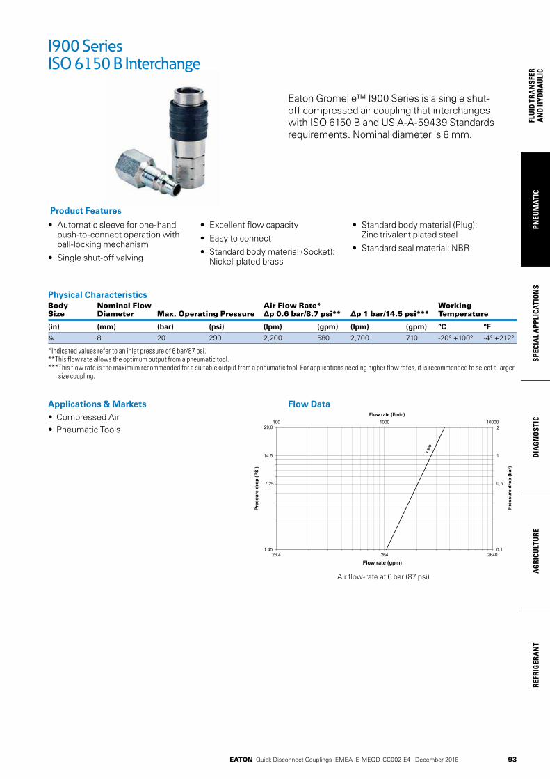
93
PNEU
MAT
ICSP
ECIA
L A
PPLI
CATI
ON
SD
IAG
NO
STIC
AG
RICU
LTU
RERE
FRIG
ERA
NT
FLU
ID T
RAN
SFER
AN
D H
YDRA
ULI
C
EATON Quick Disconnect Couplings EMEA E-MEQD-CC002-E4 December 2018
Eaton Gromelle™ I900 Series is a single shut- off compressed air coupling that interchanges with ISO 6150 B and US A-A-59439 Standards requirements. Nominal diameter is 8 mm.
• Automatic sleeve for one-hand push-to-connect operation with ball-locking mechanism
• Single shut-off valving
• Excellent flow capacity
• Easy to connect
• Standard body material (Socket): Nickel-plated brass
• Standard body material (Plug): Zinc trivalent plated steel
• Standard seal material: NBR
Product Features
Physical Characteristics Body Nominal Flow Air Flow Rate* Working Size Diameter Max. Operating Pressure ∆p 0.6 bar/8.7 psi** ∆p 1 bar/14.5 psi*** Temperature
(in) (mm) (bar) (psi) (lpm) (gpm) (lpm) (gpm) °C °F
3/8 8 20 290 2,200 580 2,700 710 -20° +100° -4° +212°
*Indicated values refer to an inlet pressure of 6 bar/87 psi. **This flow rate allows the optimum output from a pneumatic tool. *** This flow rate is the maximum recommended for a suitable output from a pneumatic tool. For applications needing higher flow rates, it is recommended to select a larger
size coupling.
I900 Series ISO 6150 B Interchange
Applications & Markets• Compressed Air • Pneumatic Tools
Flow Data
04624624.621.45
14.5
0.1
1
000010001001
Flow rate (gpm)
Pres
sure
dro
p (P
SI)
Pres
sure
dro
p (b
ar)
Flow rate (l/min)
29,0
7,25
2
0,5
Air flow-rate at 6 bar (87 psi)
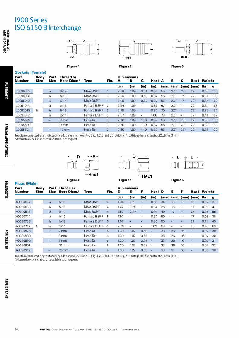
94
FLUID
TRAN
SFERA
ND
HYD
RAU
LICPN
EUM
ATICSPECIA
L APPLICATIO
NS
DIA
GN
OSTIC
AG
RICULTU
REREFRIG
ERAN
T
EATON Quick Disconnect Couplings EMEA E-MEQD-CC002-E4 December 2018
Figure 1
Sockets (Female)Part Body Port Thread or Dimensions Number Size Size Hose Diam.* Type Fig. A B C Hex1 A B C Hex1 Weight
(in) (in) (in) (in) (mm) (mm) (mm) (mm) lbs g
IL0096014 1/4 1/4-19 Male BSPT 1 2.16 1.09 0.51 0.87 55 27.7 13 22 0.30 135IL0096038 3/8 3/8-19 Male BSPT 1 2.16 1.09 0.59 0.87 55 27.7 15 22 0.31 139IL0096012 1/2 1/2-14 Male BSPT 1 2.16 1.09 0.67 0.87 55 27.7 17 22 0.34 152IL0097014 1/4 1/4-19 Female BSPP 2 2.64 1.09 - 0.87 67 27.7 - 22 0.34 153IL0097038 3/8 3/8 3/8-19 Female BSPP 2 2.76 1.09 - 0.87 70 27.7 - 22 0.35 157IL0097012 1/2 1/2-14 Female BSPP 2 2.87 1.09 - 1.06 73 27.7 - 27 0.41 187IL0095689 - 8 mm Hose Tail 3 2.20 1.09 1.10 0.87 56 27.7 28 22 0.30 135IL0095690 - 9 mm Hose Tail 3 2.20 1.09 1.10 0.87 56 27.7 28 22 0.30 138IL0095601 - 10 mm Hose Tail 3 2.20 1.09 1.10 0.87 56 27.7 28 22 0.31 139
To obtain connected length of coupling add dimensions A or A+C (Fig. 1, 2, 3) and D or D+E (Fig. 4, 5, 6) together and subtract 25,6 mm (1 in.) *Alternative end connections available upon request.
Plugs (Male)Part Body Port Thread or Dimensions Number Size Size Hose Diam.* Type Fig. D E F Hex1 D E F Hex1 Weight
(in) (in) (in) (in) (mm) (mm) (mm) (mm) lbs g
IA0090614 1/4 1/4-19 Male BSPT 4 1.34 0.51 - 0.63 34 13 - 16 0.07 32IA0090638 3/8 3/8-19 Male BSPT 4 1.42 0.59 - 0.67 36 15 - 17 0.09 41IA0090612 1/2 1/2-14 Male BSPT 4 1.57 0.67 - 0.91 40 17 - 23 0.12 56IA0090714 1/4 1/4-19 Female BSPP 5 1.97 - - 0.67 50 - - 17 0.08 38IA0090738 3/8 3/8-19 Female BSPP 5 1.97 - - 0.83 50 - - 21 0.11 49IA0090712 3/8 1/2 1/2-14 Female BSPP 5 2.09 - - 1.02 53 - - 26 0.15 69IA0090978 - 7 mm Hose Tail 6 1.30 1.02 0.63 - 33 26 16 - 0.07 30IA0090989 - 8 mm Hose Tail 6 1.30 1.02 0.63 - 33 26 16 - 0.07 30IA0090990 - 9 mm Hose Tail 6 1.30 1.02 0.63 - 33 26 16 - 0.07 31IA0090901 - 10 mm Hose Tail 6 1.30 1.02 0.63 - 33 26 16 - 0.07 32IA0090912 - 12 mm Hose Tail 6 1.30 1.22 0.63 - 33 31 16 - 0.08 38
To obtain connected length of coupling add dimensions A or A+C (Fig. 1, 2, 3) and D or D+E (Fig. 4, 5, 6) together and subtract 25,6 mm (1 in.) *Alternative end connections available upon request.
I900 Series ISO 6150 B Interchange
Figure 2 Figure 3
Figure 4 Figure 5 Figure 6

95
PNEU
MAT
ICSP
ECIA
L A
PPLI
CATI
ON
SD
IAG
NO
STIC
AG
RICU
LTU
RERE
FRIG
ERA
NT
FLU
ID T
RAN
SFER
AN
D H
YDRA
ULI
C
EATON Quick Disconnect Couplings EMEA E-MEQD-CC002-E4 December 2018
I1000 Series European Profile
Eaton Gromelle™ I1000 Series is a single shut-off compressed air coupling with a European profile. This coupling offers excellent flow capacity and is used in many compressed air applications.
• Automatic sleeve for one-hand push-to-connect operation with ball-locking mechanism
• Single shut-off valving
• Excellent flow capacity
• Easy to connect
• Standard body material (Socket): Nickel-plated brass
• Standard body material (Plug): Zinc trivalent plated steel
• Standard seal material: NBR
Product Features
Physical Characteristics Body Nominal Flow Air Flow Rate* Working Size Diameter Max. Operating Pressure ∆p 0.6 bar/8.7 psi** ∆p 1 bar/14.5 psi*** Temperature
(in) (mm) (bar) (psi) (lpm) (gpm) (lpm) (gpm) °C °F
3/8 10.3 20 290 3,000 790 3,700 980 -20° +100° -4° +212°
*Indicated values refer to an inlet pressure of 6 bar / 87 psi. **This flow rate allows the optimum output from a pneumatic tool. *** This flow rate is the maximum recommended for a suitable output from a pneumatic tool. For applications needing higher flow rates, it is recommended to select a larger
size coupling.
Applications & Markets• Compressed Air • Pneumatic Tools
Flow Data
04624624.621.45
14.5
0.1
1
000010001001
Flow rate (gpm)
Pres
sure
dro
p (P
SI)
Pres
sure
dro
p (b
ar)
Flow rate (l/min)
29,0
7,25
2
0,5
Air flow-rate at 6 bar (87 psi)
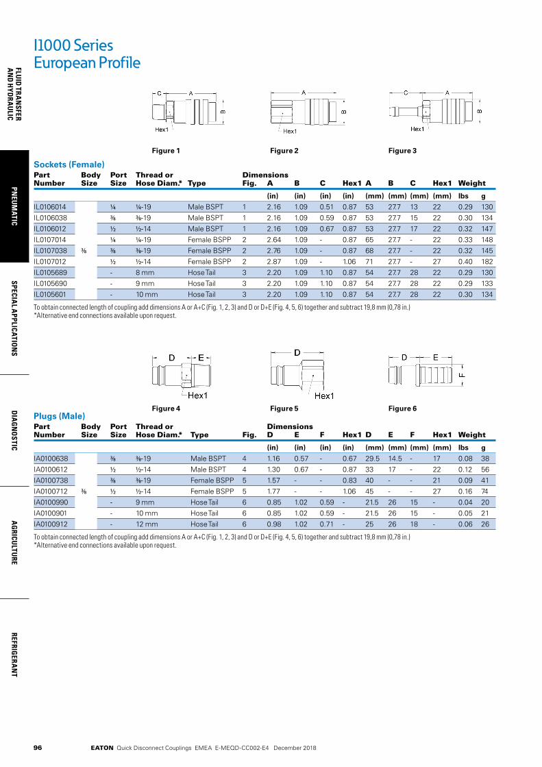
96
FLUID
TRAN
SFERA
ND
HYD
RAU
LICPN
EUM
ATICSPECIA
L APPLICATIO
NS
DIA
GN
OSTIC
AG
RICULTU
REREFRIG
ERAN
T
EATON Quick Disconnect Couplings EMEA E-MEQD-CC002-E4 December 2018
Figure 1
Sockets (Female)Part Body Port Thread or Dimensions Number Size Size Hose Diam.* Type Fig. A B C Hex1 A B C Hex1 Weight
(in) (in) (in) (in) (mm) (mm) (mm) (mm) lbs g
IL0106014 1/4 1/4-19 Male BSPT 1 2.16 1.09 0.51 0.87 53 27.7 13 22 0.29 130IL0106038 3/8 3/8-19 Male BSPT 1 2.16 1.09 0.59 0.87 53 27.7 15 22 0.30 134IL0106012 1/2 1/2-14 Male BSPT 1 2.16 1.09 0.67 0.87 53 27.7 17 22 0.32 147IL0107014 1/4 1/4-19 Female BSPP 2 2.64 1.09 - 0.87 65 27.7 - 22 0.33 148IL0107038 3/8 3/8 3/8-19 Female BSPP 2 2.76 1.09 - 0.87 68 27.7 - 22 0.32 145IL0107012 1/2 1/2-14 Female BSPP 2 2.87 1.09 - 1.06 71 27.7 - 27 0.40 182IL0105689 - 8 mm Hose Tail 3 2.20 1.09 1.10 0.87 54 27.7 28 22 0.29 130IL0105690 - 9 mm Hose Tail 3 2.20 1.09 1.10 0.87 54 27.7 28 22 0.29 133IL0105601 - 10 mm Hose Tail 3 2.20 1.09 1.10 0.87 54 27.7 28 22 0.30 134
To obtain connected length of coupling add dimensions A or A+C (Fig. 1, 2, 3) and D or D+E (Fig. 4, 5, 6) together and subtract 19,8 mm (0,78 in.) *Alternative end connections available upon request.
Plugs (Male)Part Body Port Thread or Dimensions Number Size Size Hose Diam.* Type Fig. D E F Hex1 D E F Hex1 Weight
(in) (in) (in) (in) (mm) (mm) (mm) (mm) lbs g
IA0100638 3/8 3/8-19 Male BSPT 4 1.16 0.57 - 0.67 29.5 14.5 - 17 0.08 38 IA0100612 1/2 1/2-14 Male BSPT 4 1.30 0.67 - 0.87 33 17 - 22 0.12 56 IA0100738 3/8 3/8-19 Female BSPP 5 1.57 - - 0.83 40 - - 21 0.09 41 IA0100712 3/8 1/2 1/2-14 Female BSPP 5 1.77 - - 1.06 45 - - 27 0.16 74 IA0100990 - 9 mm Hose Tail 6 0.85 1.02 0.59 - 21.5 26 15 - 0.04 20 IA0100901 - 10 mm Hose Tail 6 0.85 1.02 0.59 - 21.5 26 15 - 0.05 21 IA0100912 - 12 mm Hose Tail 6 0.98 1.02 0.71 - 25 26 18 - 0.06 26
To obtain connected length of coupling add dimensions A or A+C (Fig. 1, 2, 3) and D or D+E (Fig. 4, 5, 6) together and subtract 19,8 mm (0,78 in.) *Alternative end connections available upon request.
I1000 Series European Profile
Figure 2 Figure 3
Figure 4 Figure 5 Figure 6
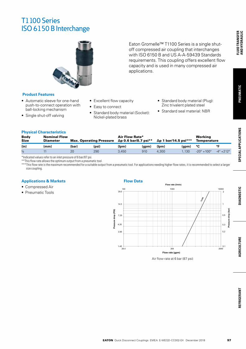
97
PNEU
MAT
ICSP
ECIA
L A
PPLI
CATI
ON
SD
IAG
NO
STIC
AG
RICU
LTU
RERE
FRIG
ERA
NT
FLU
ID T
RAN
SFER
AN
D H
YDRA
ULI
C
EATON Quick Disconnect Couplings EMEA E-MEQD-CC002-E4 December 2018
T1100 Series ISO 6150 B Interchange
Eaton Gromelle™ T1100 Series is a single shut- off compressed air coupling that interchanges with ISO 6150 B and US A-A-59439 Standards requirements. This coupling offers excellent flow capacity and is used in many compressed air applications.
• Automatic sleeve for one-hand push-to-connect operation with ball-locking mechanism
• Single shut-off valving
• Excellent flow capacity
• Easy to connect
• Standard body material (Socket): Nickel-plated brass
• Standard body material (Plug): Zinc trivalent plated steel
• Standard seal material: NBR
Product Features
Physical Characteristics Body Nominal Flow Air Flow Rate* Working Size Diameter Max. Operating Pressure ∆p 0.6 bar/8.7 psi** ∆p 1 bar/14.5 psi*** Temperature
(in) (mm) (bar) (psi) (lpm) (gpm) (lpm) (gpm) °C °F
1/2 11 20 290 3,450 910 4,300 1,130 -20° +100° -4° +212°
*Indicated values refer to an inlet pressure of 6 bar/87 psi. **This flow rate allows the optimum output from a pneumatic tool. *** This flow rate is the maximum recommended for a suitable output from a pneumatic tool. For applications needing higher flow rates, it is recommended to select a larger
size coupling.
Applications & Markets• Compressed Air • Pneumatic Tools
Flow Data
04624624.621.45
14.5
0.1
1
000010001001
Flow rate (gpm)
Pres
sure
dro
p (P
SI)
Pres
sure
dro
p (b
ar)
Flow rate (l/min)
29,0
2,90
4,35
7,25
2
0,2
0,3
0,5
Air flow-rate at 6 bar (87 psi)

98
FLUID
TRAN
SFERA
ND
HYD
RAU
LICPN
EUM
ATICSPECIA
L APPLICATIO
NS
DIA
GN
OSTIC
AG
RICULTU
REREFRIG
ERAN
T
EATON Quick Disconnect Couplings EMEA E-MEQD-CC002-E4 December 2018
Figure 1
Sockets (Female)Part Body Port Thread or Dimensions Number Size Size Hose Diam.* Type Fig. A B C Hex1 A B C Hex1 Weight
(in) (in) (in) (in) (mm) (mm) (mm) (mm) lbs g
TL0112038 3/8 3/8-19 Male BSPT 1 2.80 1.32 0.59 1.06 71 33.6 15 27 0.58 265TL0112012 1/2 1/2-14 Male BSPT 1 2.80 1.32 0.67 1.06 71 33.6 17.0 27 0.60 270TL0112034 ¾ ¾-14 Male BSPT 1 2.80 1.32 0.73 1.14 71 33.6 18.5 29 0.63 288TL0112138 3/8 3/8-19 Female BSPP 2 3.29 1.32 - 1.06 83.5 33.6 - 27 0.63 286TL0112112 1/2 1/2 1/2-14 Female BSPP 2 3.29 1.32 - 1.06 83.5 33.6 - 27 0.59 266TL0112134 ¾ ¾-14 Female BSPP 2 3.52 1.32 - 1.26 89.5 33.6 - 32 0.69 312TL0115601 - 10 mm Hose Tail 3 2.85 1.32 1.10 1.06 72.5 33.6 28 27 0.58 264TL0115613 - 13 mm Hose Tail 3 2.85 1.32 1.30 1.06 72.5 33.6 33 27 0.60 274TL0115616 - 16 mm Hose Tail 3 2.85 1.32 1.30 1.06 72.5 33.6 33 27 0.62 279
To obtain connected length of coupling add dimensions A or A+C (Fig. 1, 2, 3) and D or D+E (Fig. 4, 5, 6) together and subtract 34 mm ( 1,34 in.) *Alternative end connections available upon request.
Plugs (Male)Part Body Port Thread or Dimensions Number Size Size Hose Diam.* Type Fig. D E F Hex1 D E F Hex1 Weight
(in) (in) (in) (in) (mm) (mm) (mm) (mm) lbs g
TA0111538 3/8 3/8-19 Male BSPT 4 1.71 0.57 - 0.67 43.5 14.5 - 17 0.11 51TA0111512 1/2 1/2-14 Male BSPT 4 1.81 0.67 - 0.87 46 17 - 22 0.15 70TA0111638 3/8 3/8-19 Female BSPP 5 2.09 - - 0.83 53 - - 21 0.12 55TA0111612 1/2 1/2 1/2-14 Female BSPP 5 2.28 - - 1.06 58 - - 27 0.19 88TA0111813 - 13 mm Hose Tail 6 1.54 1.02 0.75 - 39 26 19 - 0.09 43TA0111816 - 16 mm Hose Tail 6 1.54 1.02 0.87 - 39 26 22 - 0.10 47TA0111819 - 19 mm Hose Tail 6 1.54 1.02 0.98 - 39 26 25 - 0.11 51
To obtain connected length of coupling add dimensions A or A+C (Fig. 1, 2, 3) and D or D+E (Fig. 4, 5, 6) together and subtract 34 mm ( 1,34 in.) *Alternative end connections available upon request.
T1100 Series ISO 6150 B Interchangea
Figure 2 Figure 3
Figure 4 Figure 5 Figure 6
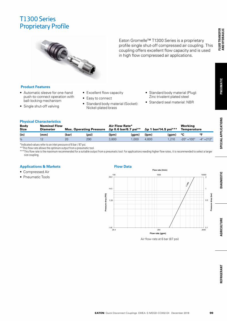
99
PNEU
MAT
ICSP
ECIA
L A
PPLI
CATI
ON
SD
IAG
NO
STIC
AG
RICU
LTU
RERE
FRIG
ERA
NT
FLU
ID T
RAN
SFER
AN
D H
YDRA
ULI
C
EATON Quick Disconnect Couplings EMEA E-MEQD-CC002-E4 December 2018
• Automatic sleeve for one-hand push-to-connect operation with ball-locking mechanism
• Single shut-off valving
• Excellent flow capacity
• Easy to connect
• Standard body material (Socket): Nickel-plated brass
• Standard body material (Plug): Zinc trivalent plated steel
• Standard seal material: NBR
Product Features
Physical Characteristics Body Nominal Flow Air Flow Rate* Working Size Diameter Max. Operating Pressure ∆p 0.6 bar/8.7 psi** ∆p 1 bar/14.5 psi*** Temperature
(in) (mm) (bar) (psi) (lpm) (gpm) (lpm) (gpm) °C °F
1/2 12 20 290 3,800 1,000 4,600 1,210 -20° +100° -4° +212°
*Indicated values refer to an inlet pressure of 6 bar / 87 psi. **This flow rate allows the optimum output from a pneumatic tool. *** This flow rate is the maximum recommended for a suitable output from a pneumatic tool. For applications needing higher flow rates, it is recommended to select a larger
size coupling.
Applications & Markets• Compressed Air • Pneumatic Tools
Flow Data
T1300 Series Proprietary Profile
Eaton Gromelle™ T1300 Series is a proprietary profile single shut-off compressed air coupling. This coupling offers excellent flow capacity and is used in high flow compressed air applications.
04624624.621.45
14.5
0.1
1
000010001001
Flow rate (gpm)
Pres
sure
dro
p (P
SI)
Pres
sure
dro
p (b
ar)
Flow rate (l/min)
29,0
7,25
2
0,5
Air flow-rate at 6 bar (87 psi)

100
FLUID
TRAN
SFERA
ND
HYD
RAU
LICPN
EUM
ATICSPECIA
L APPLICATIO
NS
DIA
GN
OSTIC
AG
RICULTU
REREFRIG
ERAN
T
EATON Quick Disconnect Couplings EMEA E-MEQD-CC002-E4 December 2018
Figure 1
Sockets (Female)Part Body Port Thread or Dimensions Number Size Size Hose Diam.* Type Fig. A B C Hex1 A B C Hex1 Weight
(in) (in) (in) (in) (mm) (mm) (mm) (mm) lbs g
TL0132038 3/8 3/8 -19 Male BSPT 1 2.74 1.32 0.59 1.06 69.7 33.6 15 27 0.54 247TL0132012 1/2 1/2 -14 Male BSPT 1 2.74 1.32 0.67 1.06 69.7 33.6 17.0 27 0.56 255TL0132034 ¾ ¾ -14 Male BSPT 1 2.74 1.32 0.73 1.14 69.7 33.6 18.5 29 0.62 279TL0132138 3/8 3/8 -19 Female BSPP 2 3.24 1.32 - 1.06 82.2 33.6 - 27 0.60 272TL0132112 1/2 1/2 1/2 -14 Female BSPP 2 3.24 1.32 - 1.06 82.2 33.6 - 27 0.60 270TL0132134 ¾ ¾ -14 Female BSPP 2 3.47 1.32 - 1.26 88.2 33.6 - 32 0.65 295TL0135601 - 10 mm Hose Tail 3 2.80 1.32 1.10 1.06 71.2 33.6 28 27 0.55 249TL0135613 - 13 mm Hose Tail 3 2.80 1.32 1.30 1.06 71.2 33.6 33 27 0.57 259TL0135616 - 16 mm Hose Tail 3 2.80 1.32 1.30 1.06 71.2 33.6 33 27 0.58 264
To obtain connected length of coupling add dimensions A or A+C (Fig. 1, 2, 3) and D or D+E (Fig. 4, 5, 6) together and subtract 32,5 mm ( 1,28 in.) *Alternative end connections available upon request.
Plugs (Male)Part Body Port Thread or Dimensions Number Size Size Hose Diam.* Type Fig. D E F Hex1 D E F Hex1 Weight
(in) (in) (in) (in) (mm) (mm) (mm) (mm) lbs g
TA0131538 3/8 3/8 -19 Male BSPT 4 1.75 0.59 - 0.83 44.5 15 - 21 0.14 65TA0131512 1/2 1/2 -14 Male BSPT 4 1.83 0.67 - 0.87 46.5 17 - 22 0.19 85TA0131638 3/8 3/8 -19 Female BSPP 5 2.17 - - 0.83 55 - - 21 0.14 65TA0131612 1/2 1/2 1/2 -14 Female BSPP 5 2.48 - - 1.02 63 - - 26 0.21 95TA0131813 - 13 mm Hose Tail 6 1.52 1.22 0.79 - 38.5 31 20 - 0.13 57TA0131816 - 16 mm Hose Tail 6 1.52 1.46 0.79 - 38.5 37 20 - 0.15 70TA0131819 - 19 mm Hose Tail 6 1.52 1.65 1.06 - 38.5 42 27 - 0.19 87
To obtain connected length of coupling add dimensions A or A+C (Fig. 1, 2, 3) and D or D+E (Fig. 4, 5, 6) together and subtract 32,5 mm ( 1,28 in.) *Alternative end connections available upon request.
T1300 Series Proprietary Profile
Figure 2 Figure 3
Figure 4 Figure 5 Figure 6
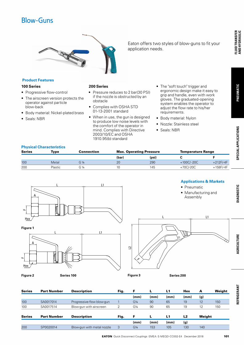
101
PNEU
MAT
ICSP
ECIA
L A
PPLI
CATI
ON
SD
IAG
NO
STIC
AG
RICU
LTU
RERE
FRIG
ERA
NT
FLU
ID T
RAN
SFER
AN
D H
YDRA
ULI
C
EATON Quick Disconnect Couplings EMEA E-MEQD-CC002-E4 December 2018
Blow-Guns
100 Series
• Progressive flow-control
• The airscreen version protects the operator against particle blow-back
• Body material: Nickel-plated brass
• Seals: NBR
200 Series
• Pressure reduces to 2 bar(30 PSI) if the nozzle is obstructed by an obstacle
• Complies with OSHA STD 01-13-2001 standard
• When in use, the gun is designed to produce low noise levels with the comfort of the operator in mind. Complies with Directive 2003/10/EC and OSHA 1910.95(b) standard
• The "soft touch" trigger and ergonomic design make it easy to grip and handle, even with work gloves. The graduated-opening system enables the operator to adjust the flow rate to his/her requirements.
• Body material: Nylon
• Nozzle: Stainless steel
• Seals: NBR
Product Features
Physical CharacteristicsSeries Type Connection Max. Operating Pressure Temperature Range
(bar) (psi) C F
100 Metal G 1/4 20 290 +100C/ -20C +212F/-4F 200 Plastic G 1/4 10 145 +70C/-20C +158F/-4F
Applications & Markets• Pneumatic • Manufacturing and
Assembly
Series Part Number Description Fig. F L L1 Hex A Weight
(mm) (mm) (mm) (mm) (g)
100 SA0017014 Progressive-flow blow-gun 1 G1/4 90 65 19 12 150 100 SA0017514 Blow-gun with airscreen 2 G1/4 90 65 19 12 150
Series Part Number Description Fig. F L L1 L2 Weight
(mm) (mm) (mm) (g)
200 SP0020014 Blow-gun with metal nozzle 3 G1/4 153 105 130 140
Eaton offers two styles of blow-guns to fit your application needs.
Series 100 Series 200
Figure 1
Figure 2 Figure 3
L L1
A
F
L L1
A
F
Hex
Hex
L L1
L2
F
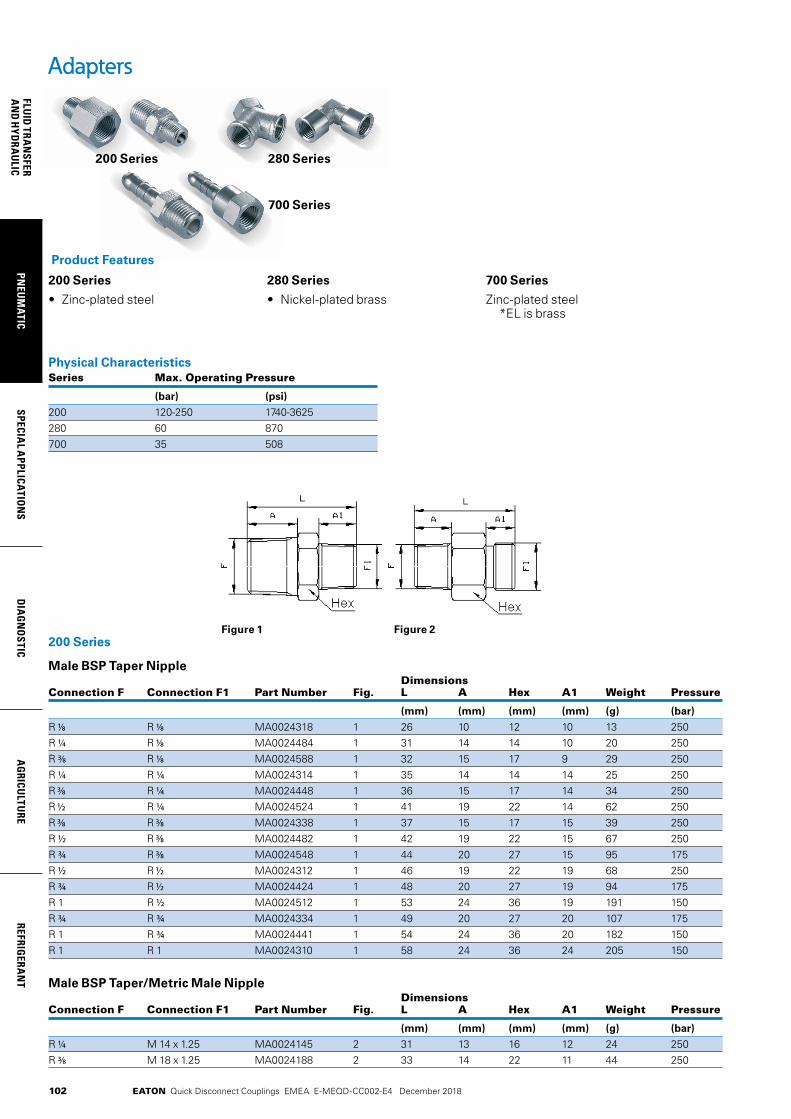
102
FLUID
TRAN
SFERA
ND
HYD
RAU
LICPN
EUM
ATICSPECIA
L APPLICATIO
NS
DIA
GN
OSTIC
AG
RICULTU
REREFRIG
ERAN
T
EATON Quick Disconnect Couplings EMEA E-MEQD-CC002-E4 December 2018
Adapters
200 Series 280 Series
700 Series
Physical CharacteristicsSeries Max. Operating Pressure
(bar) (psi)
200 120-250 1740-3625280 60 870700 35 508
200 Series
Male BSP Taper Nipple Dimensions Connection F Connection F1 Part Number Fig. L A Hex A1 Weight Pressure
(mm) (mm) (mm) (mm) (g) (bar)
R 1/8 R 1/8 MA0024318 1 26 10 12 10 13 250 R 1/4 R 1/8 MA0024484 1 31 14 14 10 20 250 R 3/8 R 1/8 MA0024588 1 32 15 17 9 29 250 R 1/4 R 1/4 MA0024314 1 35 14 14 14 25 250 R 3/8 R 1 /4 MA0024448 1 36 15 17 14 34 250 R 1/2 R 1/4 MA0024524 1 41 19 22 14 62 250 R 3/8 R 3/8 MA0024338 1 37 15 17 15 39 250 R 1/2 R 3/8 MA0024482 1 42 19 22 15 67 250 R ¾ R 3/8 MA0024548 1 44 20 27 15 95 175 R 1/2 R 1/2 MA0024312 1 46 19 22 19 68 250 R ¾ R 1/2 MA0024424 1 48 20 27 19 94 175 R 1 R 1/2 MA0024512 1 53 24 36 19 191 150 R ¾ R ¾ MA0024334 1 49 20 27 20 107 175 R 1 R ¾ MA0024441 1 54 24 36 20 182 150 R 1 R 1 MA0024310 1 58 24 36 24 205 150
Male BSP Taper/Metric Male Nipple Dimensions Connection F Connection F1 Part Number Fig. L A Hex A1 Weight Pressure
(mm) (mm) (mm) (mm) (g) (bar)
R 1/4 M 14 x 1.25 MA0024145 2 31 13 16 12 24 250 R 3/8 M 18 x 1.25 MA0024188 2 33 14 22 11 44 250
200 Series
• Zinc-plated steel
280 Series
• Nickel-plated brass
700 Series
Zinc-plated steel *EL is brass
Product Features
Figure 1 Figure 2
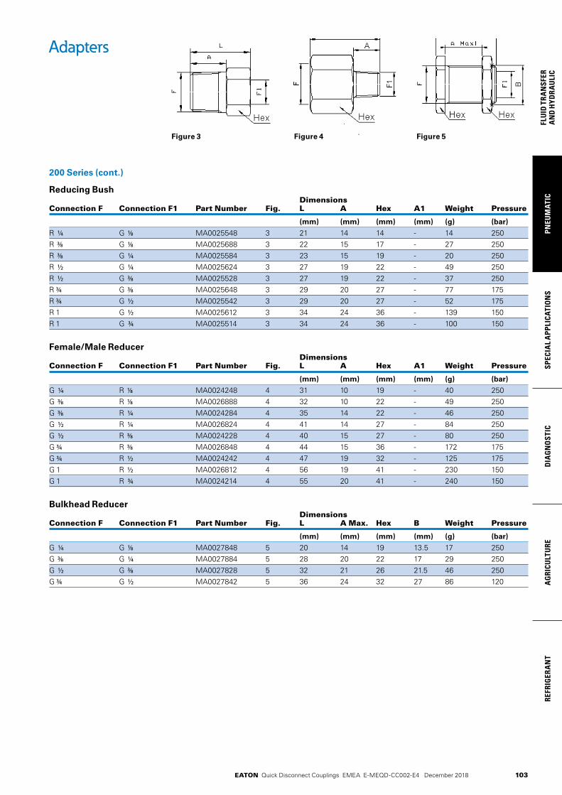
103
PNEU
MAT
ICSP
ECIA
L A
PPLI
CATI
ON
SD
IAG
NO
STIC
AG
RICU
LTU
RERE
FRIG
ERA
NT
FLU
ID T
RAN
SFER
AN
D H
YDRA
ULI
C
EATON Quick Disconnect Couplings EMEA E-MEQD-CC002-E4 December 2018
Adapters
200 Series (cont.)
Reducing Bush Dimensions Connection F Connection F1 Part Number Fig. L A Hex A1 Weight Pressure
(mm) (mm) (mm) (mm) (g) (bar)
R 1/4 G 1/8 MA0025548 3 21 14 14 - 14 250 R 3/8 G 1/8 MA0025688 3 22 15 17 - 27 250 R 3/8 G 1/4 MA0025584 3 23 15 19 - 20 250 R 1/2 G 1/4 MA0025624 3 27 19 22 - 49 250 R 1/2 G 3/8 MA0025528 3 27 19 22 - 37 250 R ¾ G 3/8 MA0025648 3 29 20 27 - 77 175 R ¾ G 1/2 MA0025542 3 29 20 27 - 52 175 R 1 G 1/2 MA0025612 3 34 24 36 - 139 150 R 1 G ¾ MA0025514 3 34 24 36 - 100 150
Female/Male Reducer Dimensions Connection F Connection F1 Part Number Fig. L A Hex A1 Weight Pressure
(mm) (mm) (mm) (mm) (g) (bar)
G 1/4 R 1/8 MA0024248 4 31 10 19 - 40 250 G 3/8 R 1/8 MA0026888 4 32 10 22 - 49 250 G 3/8 R 1/4 MA0024284 4 35 14 22 - 46 250 G 1/2 R 1/4 MA0026824 4 41 14 27 - 84 250 G 1/2 R 3/8 MA0024228 4 40 15 27 - 80 250 G ¾ R 3/8 MA0026848 4 44 15 36 - 172 175 G ¾ R 1/2 MA0024242 4 47 19 32 - 125 175 G 1 R 1/2 MA0026812 4 56 19 41 - 230 150 G 1 R ¾ MA0024214 4 55 20 41 - 240 150
Bulkhead Reducer Dimensions Connection F Connection F1 Part Number Fig. L A Max. Hex B Weight Pressure
(mm) (mm) (mm) (mm) (g) (bar)
G 1/4 G 1/8 MA0027848 5 20 14 19 13.5 17 250 G 3/8 G 1/4 MA0027884 5 28 20 22 17 29 250 G 1/2 G 3/8 MA0027828 5 32 21 26 21.5 46 250 G ¾ G 1/2 MA0027842 5 36 24 32 27 86 120
Figure 3 Figure 4 Figure 5
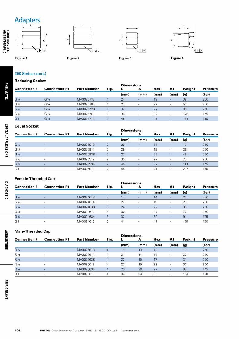
104
FLUID
TRAN
SFERA
ND
HYD
RAU
LICPN
EUM
ATICSPECIA
L APPLICATIO
NS
DIA
GN
OSTIC
AG
RICULTU
REREFRIG
ERAN
T
EATON Quick Disconnect Couplings EMEA E-MEQD-CC002-E4 December 2018
Adapters
200 Series (cont.)
Reducing Socket Dimensions Connection F Connection F1 Part Number Fig. L A Hex A1 Weight Pressure
(mm) (mm) (mm) (mm) (g) (bar)
G 1/4 G 1/8 MA0026748 1 24 - 19 - 39 250G 3/8 G 1/4 MA0026784 1 27 - 22 - 53 250G 1/2 G 3/8 MA0026728 1 32 - 27 - 89 250G ¾ G 1/2 MA0026742 1 36 - 32 - 126 175G 1 G ¾ MA0026714 1 45 - 41 - 131 150
Equal Socket Dimensions Connection F Connection F1 Part Number Fig. L A Hex A1 Weight Pressure
(mm) (mm) (mm) (mm) (g) (bar)
G 1/8 - MA0026918 2 20 - 14 - 17 250 G 1/4 - MA0026914 2 25 - 19 - 35 250 G 3/8 - MA0026938 2 27 - 22 - 45 250 G 1/2 - MA0026912 2 35 - 27 - 76 250 G ¾ - MA0026934 2 40 - 32 - 113 175 G 1 - MA0026910 2 45 - 41 - 217 150
Female-Threaded Cap Dimensions Connection F Connection F1 Part Number Fig. L A Hex A1 Weight Pressure
(mm) (mm) (mm) (mm) (g) (bar)
G 1/8 - MA0024618 3 17 - 14 - 23 250G 1/4 - MA0024614 3 22 - 19 - 29 250G 3/8 - MA0024638 3 24 - 22 - 38 250G 1/2 - MA0024612 3 30 - 27 - 70 250G ¾ - MA0024634 3 32 - 32 - 91 175G 1 - MA0024610 3 41 - 41 - 176 150
Male-Threaded Cap Dimensions Connection F Connection F1 Part Number Fig. L A Hex A1 Weight Pressure
(mm) (mm) (mm) (mm) (g) (bar)
R 1/8 - MA0026618 4 16 10 12 - 10 250 R 1/4 - MA0026614 4 21 14 14 - 22 250 R 3/8 - MA0026638 4 22 15 17 - 31 250 R 1/2 - MA0026612 4 27 19 22 - 55 250 R ¾ - MA0026634 4 29 20 27 - 89 175 R 1 - MA0026610 4 34 24 36 - 164 150
Figure 4Figure 3Figure 2Figure 1
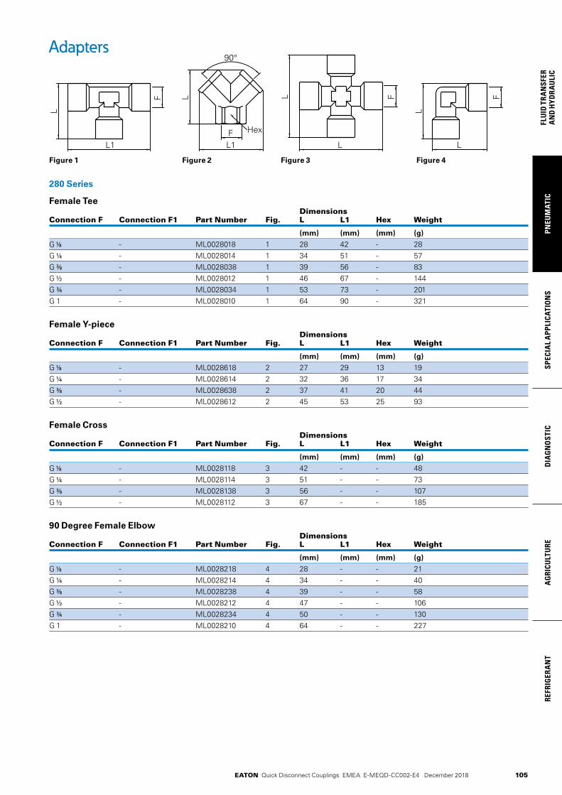
105
PNEU
MAT
ICSP
ECIA
L A
PPLI
CATI
ON
SD
IAG
NO
STIC
AG
RICU
LTU
RERE
FRIG
ERA
NT
FLU
ID T
RAN
SFER
AN
D H
YDRA
ULI
C
EATON Quick Disconnect Couplings EMEA E-MEQD-CC002-E4 December 2018
Adapters
280 Series
Female Tee Dimensions Connection F Connection F1 Part Number Fig. L L1 Hex Weight
(mm) (mm) (mm) (g)
G 1/8 - ML0028018 1 28 42 - 28G 1/4 - ML0028014 1 34 51 - 57G 3/8 - ML0028038 1 39 56 - 83G 1/2 - ML0028012 1 46 67 - 144G ¾ - ML0028034 1 53 73 - 201G 1 - ML0028010 1 64 90 - 321
Female Y-piece Dimensions Connection F Connection F1 Part Number Fig. L L1 Hex Weight
(mm) (mm) (mm) (g)
G 1/8 - ML0028618 2 27 29 13 19G 1/4 - ML0028614 2 32 36 17 34G 3/8 - ML0028638 2 37 41 20 44G 1/2 - ML0028612 2 45 53 25 93
Female Cross Dimensions Connection F Connection F1 Part Number Fig. L L1 Hex Weight
(mm) (mm) (mm) (g)
G 1/8 - ML0028118 3 42 - - 48G 1/4 - ML0028114 3 51 - - 73G 3/8 - ML0028138 3 56 - - 107G 1/2 - ML0028112 3 67 - - 185
90 Degree Female Elbow Dimensions Connection F Connection F1 Part Number Fig. L L1 Hex Weight
(mm) (mm) (mm) (g)
G 1/8 - ML0028218 4 28 - - 21G 1/4 - ML0028214 4 34 - - 40G 3/8 - ML0028238 4 39 - - 58G 1/2 - ML0028212 4 47 - - 106G ¾ - ML0028234 4 50 - - 130G 1 - ML0028210 4 64 - - 227
Figure 3Figure 1 Figure 2 Figure 4
L1F
L90°
F
L
L1
Hex
L
FL
L
F
L

106
FLUID
TRAN
SFERA
ND
HYD
RAU
LICPN
EUM
ATICSPECIA
L APPLICATIO
NS
DIA
GN
OSTIC
AG
RICULTU
REREFRIG
ERAN
T
EATON Quick Disconnect Couplings EMEA E-MEQD-CC002-E4 December 2018
280 Series (cont.)
90 Degree Male/Female Elbow Dimensions Connection F Connection F1 Part Number Fig. L L1 Hex Weight
(mm) (mm) (mm) (g)
G 1/8 - ML0028418 5 26 26 - 17G 1/4 - ML0028414 5 32 32 - 34G 3/8 - ML0028438 5 37 37 - 50G 1/2 - ML0028412 5 44 44 - 89G ¾ - ML0028434 5 50 50 - 124G 1 - ML0028410 5 60 60 - 206
700 Series
Male-Threaded Hose Tail Dimensions Connection F Hose I.D. Part Number Fig. L A Hex Weight
(mm) (mm) (mm) (mm) (g)
R 1/8 6 EL0070267 1 32 7.5 12 10R 1/8 7 EA0070278 1 41 9 14 15R 1/8 8 EA0070289 1 41 9 14 16R 1/8 9 EA0070290 1 41 9 14 18R 1/4 6 EA0070467 1 45 13 14 18R 1/4 7 EA0070478 1 45 13 14 19R 1/4 8 EA0070489 1 45 13 14 20R 1/4 9 EA0070490 1 45 13 14 20R 1/4 10 EA0070401 1 45 13 14 21R 1/4 11 EA0070411 1 50 13 14 24R 1/4 12 EA0070412 1 50 13 17 31R 1/4 13 EA0070413 1 50 13 17 36R 3/8 7 EA0070678 1 48 14 17 31R 3/8 8 EA0070689 1 48 14 17 32R 3/8 9 EA0070690 1 48 14 17 33R 3/8 10 EA0070601 1 48 14 17 33R 3/8 11 EA0070611 1 49 14 17 33R 3/8 12 EA0070612 1 53 14 17 36R 3/8 13 EA0070613 1 53 14 19 43R 3/8 16 EA0070616 1 60 14 19 50R 1/2 8 EA0070889 1 52 17 22 50R 1/2 11 EA0070811 1 57 17 22 55R 1/2 12 EA0070812 1 57 17 22 55R 1/2 13 EA0070813 1 57 17 22 58R 1/2 16 EA0070816 1 63 17 22 61R 1/2 19 EA0070819 1 69 17 22 73R ¾ 16 EA0071016 1 65 19 27 85R ¾ 19 EA0071019 1 71 19 27 100R ¾ 25 EA0071025 1 77 19 27 130R 1 19 EA0072019 1 76 22 35 165R 1 25 EA0072025 1 82 22 35 203R 1 30 EA0072030 1 94 22 35 270
Adapters L1
F
L
F1
Figure 5
Figure 1
I.DA
L
F
Hex
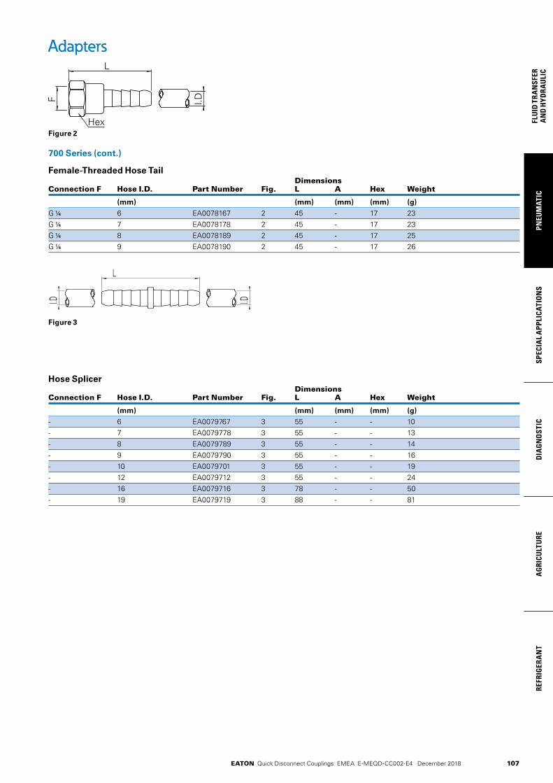
107
PNEU
MAT
ICSP
ECIA
L A
PPLI
CATI
ON
SD
IAG
NO
STIC
AG
RICU
LTU
RERE
FRIG
ERA
NT
FLU
ID T
RAN
SFER
AN
D H
YDRA
ULI
C
EATON Quick Disconnect Couplings EMEA E-MEQD-CC002-E4 December 2018
700 Series (cont.)
Female-Threaded Hose Tail Dimensions Connection F Hose I.D. Part Number Fig. L A Hex Weight
(mm) (mm) (mm) (mm) (g)
G 1/4 6 EA0078167 2 45 - 17 23G 1/4 7 EA0078178 2 45 - 17 23G 1/4 8 EA0078189 2 45 - 17 25G 1/4 9 EA0078190 2 45 - 17 26
Hose Splicer Dimensions Connection F Hose I.D. Part Number Fig. L A Hex Weight
(mm) (mm) (mm) (mm) (g)
- 6 EA0079767 3 55 - - 10- 7 EA0079778 3 55 - - 13- 8 EA0079789 3 55 - - 14- 9 EA0079790 3 55 - - 16- 10 EA0079701 3 55 - - 19- 12 EA0079712 3 55 - - 24- 16 EA0079716 3 78 - - 50- 19 EA0079719 3 88 - - 81
Adapters
Figure 2
I.D
L
F
Hex
I.DI.D
L
Figure 3

EATON Quick Disconnect Couplings EMEA E-MEQD-CC002-E4 December 2018108
FLUID
TRAN
SFERA
ND
HYD
RAU
LICPN
EUM
ATICSPECIA
L APPLICATIO
NS
DIA
GN
OSTIC
AG
RICULTU
REREFRIG
ERAN
T
108
FLUID
TRAN
SFERA
ND
HYD
RAU
LICPN
EUM
ATICSPECIA
L APPLICATIO
NS
DIA
GN
OSTIC
AG
RICULTU
REREFRIG
ERAN
T
Hose Reels
SPUBD Series
• Tube material: Polyurethane
• Swivel connections: Nickel-plated brass
ENR Series
• Guard material: Steel
• Polyurethane braided hose
• Plug material: Brass
• Swivel joint material: Steel
Product Features
Eaton offers air hose reels and coil assemblies for pneumatic applications.
Applications & Markets• Pneumatic • Manufacturing and
Assembly
Physical CharacteristicsSeries Connection Max. Operating Pressure Temperature Range
(bar) (psi) C F
SPUBD G 1/4 x G1/4 9 130.5 +50C/-40C +122F/-40F ENR R 1/4 15 220 +60C/-5C +140F/+23F
Series Part Number Connection Hose I.D./O.D. Max. Length Min. Length Coil Diameter Color
(mm) (m) (cm) (mm)
SPUBD SPUBD0584E G 1/4 x G 1/4 5 x 8 4 25 60 Blue SPUBD SPUBD65104E G 1/4 x G 1/4 6.5 x 10 4 32 70 Blue
End Hose Series Part Number Connection Hose I.D./O.D. L1 L2 H I1 I2 Length Weight
(mm) (mm) (mm) (mm) (mm) (mm) (m) (g)
ENR ENRTPU081210E R 1/4 8 x 12 345 380 320 121 170 10 9.5

EATON Quick Disconnect Couplings EMEA E-MEQD-CC002-E4 December 2018 109
PNEU
MAT
ICSP
ECIA
L A
PPLI
CATI
ON
SD
IAG
NO
STIC
AG
RICU
LTU
RERE
FRIG
ERA
NT
FLU
ID T
RAN
SFER
AN
D H
YDRA
ULI
C
FD17 Series
The Eaton FD17 high pressure coupling can be connected by hand while under pressure up to 5,500 psi/380 bar. This quick disconnect coupling is most commonly used in SCBA transfilling and buddy-breathing applications and is commonly found on SCBA equipment certified to various NIOSH, NFPA and CBRN standards.
Eaton® FD17 Series Quick Disconnect Coupling
Eaton FD17 high pressure quick disconnect coupling is designed for use in breathable air transfilling applications
Product Features
• Connectanddisconnectunderpressuresupto4,500psi/310bar
• CertifiedonSCBAequipmentthatmeetsNIOSH,NFPA,and
CBRNrequirements
• ComplieswithNFPA1981
• Standardbodymaterial:StainlessSteel,Aluminum
Eatonhasover25yearsofprovenexperienceandserviceinsupportofSCBAindustrywithquickdisconnectcouplings.Eaton’sFD17setstheindustrystandardwithit’sproven,reliabledesignandpresenceasaninnovativeproductinthemarket.
TheEatonFD17highpressurecouplingisdesignedforuseinbreathableairtransfillingapplications†.Thiscouplingcanbeconnectedbyhandwhileunderpressureupto4,500psi/310bar.ThisquickdisconnectcouplingismostcommonlyusedinbreathableairSCBAtransfillingandbuddybreathingapplicationsandiscommonlyfoundonSCBAequipmentcertifiedtovariousNIOSH,NFPAandCBRNstandards. Physical Characteristics
*Rated at 6.9 bar (100 psi)
† For other application opportunities not mentioned please contact an Eaton Sales Representative.
SeriesMax. Operating
PressureMin. Burst Pressure
Rated Flow*
Rated Temperature
bar psi bar psi lpm CFM
FD17 310 4,500 930 13,500 125 4.4 -25°F(-32°C)/+160°F(+71°C)
• Connect and disconnect under pressure up to 5,500 psi/380 bar
• Certified on SCBA equipment that meets NIOSH, NFPA and CBRN requirements
• Complies with NFPA 1981 and NFPA 2013
• Standard body material: Stainless steel, aluminum
Product Features
Physical Characteristics Series Max. Operating Pressure Min. Burst Pressure Rated Flow* Rated Temperature
(bar) (psi) (bar) (psi) (lpm) scfm
FD17 380 5,500 1140 16,500 125 4.4 -40°F (-40°C)/+160°F (+71°C)
©2013EatonAllRightsReservedPrintedinUSADocumentNo.E-MEQD-BB001-E June2013
Eaton HydraulicsGroupUSA 14615LoneOakRoad EdenPrairie,MN55344 USA Tel:952-937-9800 Fax:952-294-7722 www.eaton.com/hydraulics
EatonHydraulicsGroupEuropeRoutedelaLongeraie71110MorgesSwitzerlandTel:+41(0)218114600Fax:+41(0)218114601
EatonHydraulicsGroupAsiaPacificEatonBuildingNo.7Lane280LinhongRoadChangningDistrict,Shanghai200335ChinaTel:(+8621)52000099Fax:(+8621)22307240
Eaton Male Cap Part Number
FD17-1064-04
Eaton Female Cap Part Number
FD17-1062-04
Part Number Fig. Coupling Type Body Size Port Size Thread Type A (in) B (in) Hex (in)A
(mm)B
(mm)Hex
(mm)
FD17-1003-04-04 1 Socket/Female 1/4” -.4 7/16-20 ORB 2.85 1.38 0.75 72.4 35.1 19.1
FD17-1002-10-04 2 Plug/Male 1/4” -.10 7/8-14 ORB 1.93 1.43 1 49.0 36.3 25.4
Dimensions
Figure 1 Figure 2
A
A
B B
HEX
HEX
©2013EatonAllRightsReservedPrintedinUSADocumentNo.E-MEQD-BB001-E June2013
Eaton HydraulicsGroupUSA 14615LoneOakRoad EdenPrairie,MN55344 USA Tel:952-937-9800 Fax:952-294-7722 www.eaton.com/hydraulics
EatonHydraulicsGroupEuropeRoutedelaLongeraie71110MorgesSwitzerlandTel:+41(0)218114600Fax:+41(0)218114601
EatonHydraulicsGroupAsiaPacificEatonBuildingNo.7Lane280LinhongRoadChangningDistrict,Shanghai200335ChinaTel:(+8621)52000099Fax:(+8621)22307240
Eaton Male Cap Part Number
FD17-1064-04
Eaton Female Cap Part Number
FD17-1062-04
Part Number Fig. Coupling Type Body Size Port Size Thread Type A (in) B (in) Hex (in)A
(mm)B
(mm)Hex
(mm)
FD17-1003-04-04 1 Socket/Female 1/4” -.4 7/16-20 ORB 2.85 1.38 0.75 72.4 35.1 19.1
FD17-1002-10-04 2 Plug/Male 1/4” -.10 7/8-14 ORB 1.93 1.43 1 49.0 36.3 25.4
Dimensions
Figure 1 Figure 2
A
A
B B
HEX
HEXFigure 1 Figure 2
Part Coupling Body Port Dimensions Number Type Size Size Thread Type Fig. A B Hex A B Hex
(in) (in) (in) (mm) (mm) (mm)
FD17-1003-04-04 Socket/Female 1/4 -4 7/16-20 ORB 1 2.85 1.38 0.75 72.4 35.1 19.1FD17-1082-10-04 Plug/Male 1/4 -10 7/8-14 ORB 2 1.93 1.43 1 49.0 36.3 25.4
©2013EatonAllRightsReservedPrintedinUSADocumentNo.E-MEQD-BB001-E June2013
Eaton HydraulicsGroupUSA 14615LoneOakRoad EdenPrairie,MN55344 USA Tel:952-937-9800 Fax:952-294-7722 www.eaton.com/hydraulics
EatonHydraulicsGroupEuropeRoutedelaLongeraie71110MorgesSwitzerlandTel:+41(0)218114600Fax:+41(0)218114601
EatonHydraulicsGroupAsiaPacificEatonBuildingNo.7Lane280LinhongRoadChangningDistrict,Shanghai200335ChinaTel:(+8621)52000099Fax:(+8621)22307240
Eaton Male Cap Part Number
FD17-1064-04
Eaton Female Cap Part Number
FD17-1062-04
Part Number Fig. Coupling Type Body Size Port Size Thread Type A (in) B (in) Hex (in)A
(mm)B
(mm)Hex
(mm)
FD17-1003-04-04 1 Socket/Female 1/4” -.4 7/16-20 ORB 2.85 1.38 0.75 72.4 35.1 19.1
FD17-1002-10-04 2 Plug/Male 1/4” -.10 7/8-14 ORB 1.93 1.43 1 49.0 36.3 25.4
Dimensions
Figure 1 Figure 2
A
A
B B
HEX
HEX
Male Dust Cap Part Number
FD17-1064-04*
* Indicates patented product
Female Dust Cap Part Number
FD17-1062-04
©2013EatonAllRightsReservedPrintedinUSADocumentNo.E-MEQD-BB001-E June2013
Eaton HydraulicsGroupUSA 14615LoneOakRoad EdenPrairie,MN55344 USA Tel:952-937-9800 Fax:952-294-7722 www.eaton.com/hydraulics
EatonHydraulicsGroupEuropeRoutedelaLongeraie71110MorgesSwitzerlandTel:+41(0)218114600Fax:+41(0)218114601
EatonHydraulicsGroupAsiaPacificEatonBuildingNo.7Lane280LinhongRoadChangningDistrict,Shanghai200335ChinaTel:(+8621)52000099Fax:(+8621)22307240
Eaton Male Cap Part Number
FD17-1064-04
Eaton Female Cap Part Number
FD17-1062-04
Part Number Fig. Coupling Type Body Size Port Size Thread Type A (in) B (in) Hex (in)A
(mm)B
(mm)Hex
(mm)
FD17-1003-04-04 1 Socket/Female 1/4” -.4 7/16-20 ORB 2.85 1.38 0.75 72.4 35.1 19.1
FD17-1002-10-04 2 Plug/Male 1/4” -.10 7/8-14 ORB 1.93 1.43 1 49.0 36.3 25.4
Dimensions
Figure 1 Figure 2
A
A
B B
HEX
HEX

110
FLUID
TRAN
SFERA
ND
HYD
RAU
LICPN
EUM
ATICSPECIA
L APPLICATIO
NS
DIA
GN
OSTIC
AG
RICULTU
REREFRIG
ERAN
T
EATON Quick Disconnect Couplings EMEA E-MEQD-CC002-E3 December 2018
FD69 Series 10,000 psi Water Blast
Eaton’s FD69 Series design has a greater surface contact area for long service life in rugged high pressure and water blast applications. The maximum operating pressure is 10,000 psi with 40,000 psi minimum burst pressure.
Product Features• Safety sleeve lock guards
against accidental disconnection
• Smooth bore “straight through” design for high flow fluid requirements
• Heavy duty back-up ring to prevent O-Ring extrusion
• Available in plated steel and stainless steel for added corrosion resistance
• Standard seal material: Buna-N
• Standard body material: High resistance carbon steel with Zinc trivalent plating or stainless steel
Flow DataPressure Drop Versus Flow Graph
Gallons Per Minute FlowTest Fluid: Water at 70°F
40 60 80 100 120 140 200 240 300 3800.05
0.1
0.2
0.3
0.5
1
2
3
bar
lpm
10.6 15.8 21.1 26.4 37 52.8 63.4 79.2 100.3
0.725
1.45
2.9
4.35
7.25
14.5
29
43.5
gpmps
i
Physical Characteristics Coupling Max. Operating Min. Burst Pressure Vacuum Rated Air Fluid Size Pressure Connected Connected Only Flow Inclusion Loss
(in) (bar) (psi) (bar) (psi) (in./Hg) (lpm) (gpm) cc. max. cc.max.
1/2 689 10,000 2,758 40,000 28 170 45 - -
Applications & Markets• High pressure WaterBlast• Bridge/Concrete Repair• Paint Stripping• Shipyards
1/2
Pre
ssu
re D
rop
, bar

111
PNEU
MAT
ICSP
ECIA
L A
PPLI
CATI
ON
SD
IAG
NO
STIC
AG
RICU
LTU
RERE
FRIG
ERA
NT
FLU
ID T
RAN
SFER
AN
D H
YDRA
ULI
C
EATON Quick Disconnect Couplings EMEA E-MEQD-CC002-E3 December 2018
Dimensions (Female NPT)Part Number Coupling Body Port Dimensions Buna-N FKM EPDM Type Size Size Thread Type Fig. A B Hex 1
Steel mm (in) mm (in) mm (in)
FD69-1002-06-08 FD69-1002-06-08 FD69-1002-06-08 Plug/Male* 1/2 3/8 3/8-18 Female NPT 1 47.0 (1.85) 41.7 (1.64) 25.4 (1.00
FD69-1001-06-08 FD69-1026-06-08 FD69-1028-06-08 Socket/Female 1/2 3/8 3/8-18 Female NPT 2 54.1 (2.13) 41.1 (1.62) 31.8 (1.25)
FD69-1002-08-08 FD69-1002-08-08 FD69-1002-08-08 Plug/Male* 1/2 1/2 1/2-14 Female NPT 1 59.4 (2.34) 41.7 (1.64) 28.4 (1.12)
FD69-1001-08-08 FD69-1026-08-08 FD69-1028-08-08 Socket/Female 1/2 1/2 1/2-14 Female NPT 2 54.1 (2.13) 41.1 (1.62) 31.8 (1.25)
Stainless Steel
FD69-1012-08-08 FD69-1012-08-08 FD69-1012-08-08 Plug/Male* 1/2 1/2 1/2-14 Female NPT 1 59.4 (2.34) 41.7 (1.64) 28.4 (1.12)
FD69-1011-08-08 - - Socket/Female 1/2 1/2 1/2-14 Female NPT 2 54.1 (2.13) 41.1 (1.62) 33.3 (1.31)
*Male halves contain no seals.
Part Number Coupling Body Port Thread Dimensions Buna-N FKM EPDM Type Size Size (P) (P1) Type Fig. A
Steel mm (in)
FD69-1000-080808 FD69-1027-080808 FD69-1029-080808 Complete 1/2 1/2 1/2-14 1/2-14 Female NPT 3 87.1 (3.43)
FD69-1000-080806 FD69-1027-080806 FD69-1029-080806 Complete 1/2 1/2 & 3/8 1/2-14 3/8-18 Female NPT 3 87.1 (3.43)
FD69-1000-060808 FD69-1027-060808 FD69-1029-060808 Complete 1/2 3/8 & 1/2 3/8-18 1/2-14 Female NPT 3 74.7 (2.94)
FD69-1000-060806 FD69-1027-060806 FD69-1029-060806 Complete 1/2 3/8 3/8-18 3/8-18 Female NPT 3 74.7 (2.94)
Stainless Steel
FD69-1010-080808 - - Complete 1/2 1/2 1/2-14 1/2-14 Female NPT 3 87.1 (3.43)
Repair Kit, Female Interface SealPart Number Coupling Buna-N Size
FF10166 1/2
Figure 2 Figure 3Figure 1
FD69 Series 10,000 psi Water Blast
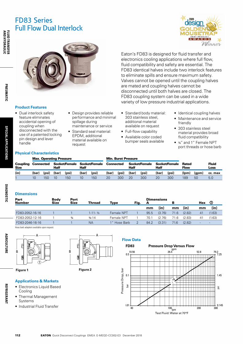
112
FLUID
TRAN
SFERA
ND
HYD
RAU
LICPN
EUM
ATICSPECIA
L APPLICATIO
NS
DIA
GN
OSTIC
AG
RICULTU
REREFRIG
ERAN
T
EATON Quick Disconnect Couplings EMEA E-MEQD-CC002-E3 December 2018
Pressure Drop Versus Flow Pressure Drop Versus FlowFD99FD96
Pressure Drop Versus FlowFD83 Pressure Drop Versus FlowFD89
1 10 100 1000 20000.1
1
10
bar
lpm
0.264 2.64 26.4 264 528
1.45
14.5
145
gpm
psi
40 100 200 3000.01
0.1
0.5
bar
lpm
10.56 26.4 52.8 79.2
0.145
1.45
7.25
gpm
psi
1 10 100 1000 40000.1
1
10
bar
lpm
0.264 2.64 26.4 264 1056
1.45
14.5
145
gpm
psi
1 10 100 1000 20000.1
1
10
bar
lpm
0.264 2.64 26.4 264 528
1.45
14.5
145
psi
gpm
-04
-06
-06
-08
-08
-10
-10
-12
-12
-16
-16
-20
-24
-24
-32
-16
-04
-06
-08
-10
-12
-16 -24
-32-04
Test Fluid: Water at 70°F
Pre
ssu
re D
rop
, bar
FD83 Series Full Flow Dual Interlock
Eaton’s FD83 is designed for fluid transfer and electronics cooling applications where full flow, fluid compatibility and safety are essential. The FD83 identical halves include two interlock features to eliminate spills and ensure maximum safety. Valves cannot be opened until the coupling halves are mated and coupling halves cannot be disconnected until both halves are closed. The FD83 coupling system can be used in a wide variety of low pressure industrial applications.
Applications & Markets• Electronics Liquid Based
Cooling• Thermal Management
Systems• Industrial Fluid Transfer
• Dual interlock safety feature eliminates accidental opening of coupling when disconnected with the use of a patented locking pin design and lever handle
• Design provides reliable performance and minimal spillage during maintenance or service
• Standard seal material: EPDM, additional material available on request
• Standard body material: 303 stainless steel, additional material available on request
• Full-flow capability • Available color coded
bumper seals available
• Identical coupling halves• Maintenance and service
friendly• 303 stainless steel
material provides broad fluid compatibility
• ¾” and 1” Female NPT port threads or hose barb
Product Features
Flow Data
DimensionsPart Body Port Dimensions Number Size Size Thread Type Fig. A B Hex
mm (in) mm (in) mm (in) FD83-2052-16-16 1 1 1-11- 1/2 Female NPT 1 95.5 (3.76) 71.6 (2.82) 41 (1.63) FD83-2052-12-16 1 ¾ ¾-14 Female NPT 1 70.1 (2.76) 71.6 (2.83) 41 (1.63) FD83-2046-16-16 1 1 NA 1” Hose Barb 2 84.2 (3.31) 71.6 (2.82) - - Hose barb adapters available upon request.
1
Figure 1 Figure 2
Physical Characteristics Max. Operating Pressure Min. Burst Pressure
Coupling Connected Socket/Female Socket/Female Connected Socket/Female Socket/Female Rated Fluid Size Half Half Half Half Flow Loss
(in) (bar) (psi) (bar) (psi) (bar) (psi) (bar) (psi) (bar) (psi) (bar) (psi) (lpm) (gpm) cc. max 1 10 150 10 150 10 150 20 300 20 300 20 300 189 50 5.0
1
A
B
A
B
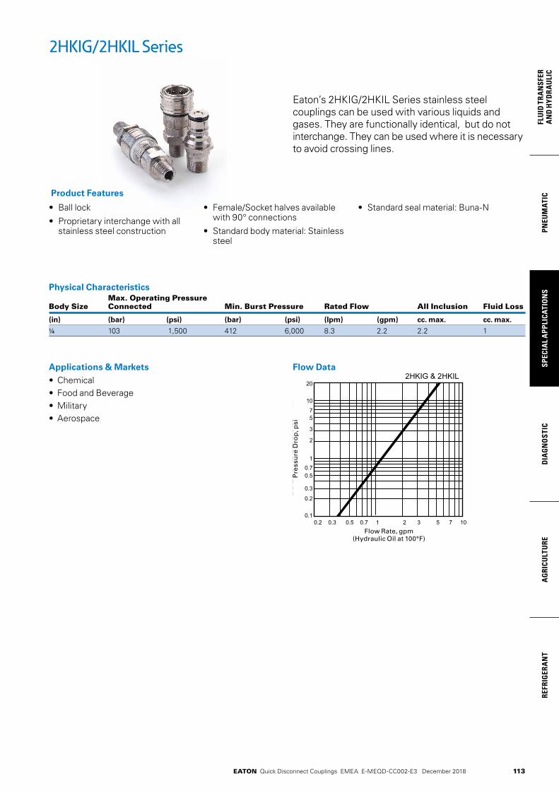
113
PNEU
MAT
ICSP
ECIA
L A
PPLI
CATI
ON
SD
IAG
NO
STIC
AG
RICU
LTU
RERE
FRIG
ERA
NT
FLU
ID T
RAN
SFER
AN
D H
YDRA
ULI
C
EATON Quick Disconnect Couplings EMEA E-MEQD-CC002-E3 December 2018
Eaton’s 2HKIG/2HKIL Series stainless steel couplings can be used with various liquids and gases. They are functionally identical, but do not interchange. They can be used where it is necessary to avoid crossing lines.
• Ball lock
• Proprietary interchange with all stainless steel construction
• Female/Socket halves available with 90° connections
• Standard body material: Stainless steel
• Standard seal material: Buna-N
Product Features
Physical Characteristics Max. Operating Pressure Body Size Connected Min. Burst Pressure Rated Flow All Inclusion Fluid Loss
(in) (bar) (psi) (bar) (psi) (lpm) (gpm) cc. max. cc. max.
1/4 103 1,500 412 6,000 8.3 2.2 2.2 1
2HKIG/2HKIL Series
Applications & Markets• Chemical• Food and Beverage• Military• Aerospace
Flow Data
Pre
ssu
re D
rop
, psi
Flow Rate, gpm(Hydraulic Oil at 100°F)

114
FLUID
TRAN
SFERA
ND
HYD
RAU
LICPN
EUM
ATICSPECIA
L APPLICATIO
NS
DIA
GN
OSTIC
AG
RICULTU
REREFRIG
ERAN
T
EATON Quick Disconnect Couplings EMEA E-MEQD-CC002-E3 December 2018
2HKIG Series
Male End ConnectionsPart Coupling Body Dimensions Number Type Size Thread Fig. A B Hex A B Hex
(in) (in) (in) (mm) (mm) (mm)
2HIG10 Socket/Female 1/4 1/8-27 NPTF 1 2.18 1.06 0.81 55.4 26.9 20.62HIG15 Socket/Female 1/4 1/4-18 NPTF 1 2.31 1.06 0.81 58.7 26.9 20.62HIG20 Socket/Female 1/4 3/8-18 NPTF 1 2.31 1.06 0.81 58.7 26.9 20.62HIG720 Socket/Female 1/4 7/16-20 NPTF 1 2.27 1.06 0.81 57.7 26.9 20.62HIGLLRA720 Socket/Female 1/4 7/16-20 NPTF 3 2.09 1.06 — 53.1 26.9 —Part Coupling Body Dimensions Number Type Size Thread Fig. C D Hex C D Hex
(in) (in) (in) (mm) (mm) (mm
2KIGF15 Plug/Male 1/4 1/4-18 NPTF 2 1.98 1.01 0.69 50.3 25.7 17.52KIGF20 Plug/Male 1/4 3/8-18 NPTF 2 1.98 1.01 0.69 50.3 25.7 17.5
Female End ConnectionsPart Coupling Body Dimensions Number Type Size Thread Fig. A B Hex A B Hex
(in) (in) (in) (mm) (mm) (mm)
2HIG11 Socket/Female 1/4 1/8 -27 NPTF 1 2.18 1.06 0.81 55.4 26.9 20.62HIG16 Socket/Female 1/4 1/4-18 NPTF 1 2.26 1.06 0.81 57.4 26.9 20.6Part Coupling Body Dimensions Number Type Size Thread Fig. C D Hex C D Hex
(in) (in) (in) (mm) (mm) (mm)
2KIGF16 Plug/Male 1/4 1/4 -18 NPTF 2 1.84 1.01 0.69 46.7 25.7 17.52KIGF720 Plug/Male 1/4 7/16 -20 2 1.61 1.01 0.69 40.9 25.7 17.52KIGF Plug/Male 1/4 9/16 -18 2 1.17 1.01 0.68 29.7 25.7 17.3
Figure 1 Figure 2 Figure 3
Figure 1 Figure 2
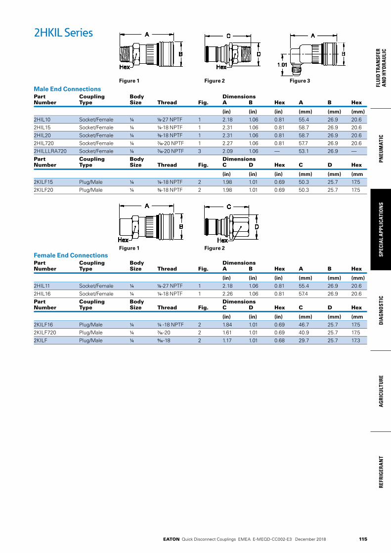
115
PNEU
MAT
ICSP
ECIA
L A
PPLI
CATI
ON
SD
IAG
NO
STIC
AG
RICU
LTU
RERE
FRIG
ERA
NT
FLU
ID T
RAN
SFER
AN
D H
YDRA
ULI
C
EATON Quick Disconnect Couplings EMEA E-MEQD-CC002-E3 December 2018
2HKIL Series
Male End ConnectionsPart Coupling Body Dimensions Number Type Size Thread Fig. A B Hex A B Hex
(in) (in) (in) (mm) (mm) (mm)
2HIL10 Socket/Female 1/4 1/8-27 NPTF 1 2.18 1.06 0.81 55.4 26.9 20.6 2HIL15 Socket/Female 1/4 1/4-18 NPTF 1 2.31 1.06 0.81 58.7 26.9 20.6 2HIL20 Socket/Female 1/4 3/8-18 NPTF 1 2.31 1.06 0.81 58.7 26.9 20.6 2HIL720 Socket/Female 1/4 7/16-20 NPTF 1 2.27 1.06 0.81 57.7 26.9 20.6 2HILLLRA720 Socket/Female 1/4 7/16-20 NPTF 3 2.09 1.06 — 53.1 26.9 —Part Coupling Body Dimensions Number Type Size Thread Fig. C D Hex C D Hex
(in) (in) (in) (mm) (mm) (mm
2KILF15 Plug/Male 1/4 1/4-18 NPTF 2 1.98 1.01 0.69 50.3 25.7 17.5 2KILF20 Plug/Male 1/4 3/8-18 NPTF 2 1.98 1.01 0.69 50.3 25.7 17.5
Female End ConnectionsPart Coupling Body Dimensions Number Type Size Thread Fig. A B Hex A B Hex
(in) (in) (in) (mm) (mm) (mm)
2HIL11 Socket/Female 1/4 1/8 -27 NPTF 1 2.18 1.06 0.81 55.4 26.9 20.62HIL16 Socket/Female 1/4 1/4-18 NPTF 1 2.26 1.06 0.81 57.4 26.9 20.6Part Coupling Body Dimensions Number Type Size Thread Fig. C D Hex C D Hex
(in) (in) (in) (mm) (mm) (mm
2KILF16 Plug/Male 1/4 1/4 -18 NPTF 2 1.84 1.01 0.69 46.7 25.7 17.52KILF720 Plug/Male 1/4 7/16 -20 2 1.61 1.01 0.69 40.9 25.7 17.52KILF Plug/Male 1/4 9/16 -18 2 1.17 1.01 0.68 29.7 25.7 17.3
Figure 1 Figure 2 Figure 3
Figure 1 Figure 2
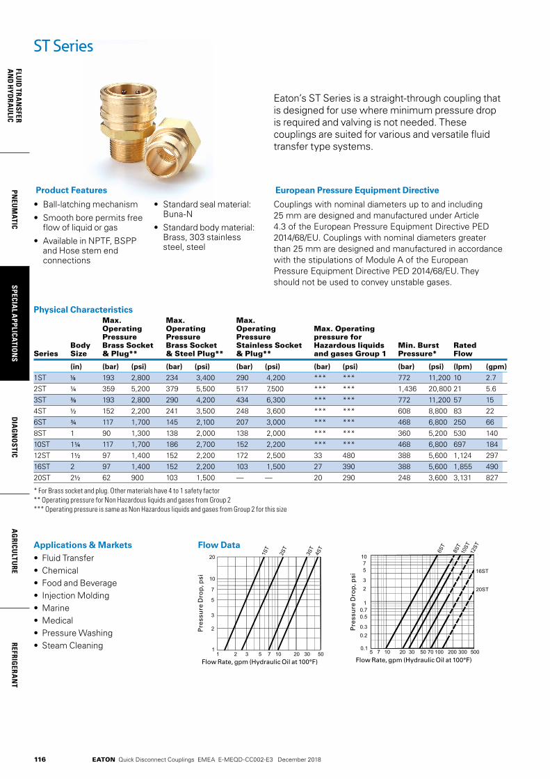
116
FLUID
TRAN
SFERA
ND
HYD
RAU
LICPN
EUM
ATICSPECIA
L APPLICATIO
NS
DIA
GN
OSTIC
AG
RICULTU
REREFRIG
ERAN
T
EATON Quick Disconnect Couplings EMEA E-MEQD-CC002-E3 December 2018
Eaton’s ST Series is a straight-through coupling that is designed for use where minimum pressure drop is required and valving is not needed. These couplings are suited for various and versatile fluid transfer type systems.
• Ball-latching mechanism
• Smooth bore permits free flow of liquid or gas
• Available in NPTF, BSPP and Hose stem end connections
• Standard seal material: Buna-N
• Standard body material: Brass, 303 stainless steel, steel
Product Features
Physical Characteristics Max. Max. Max. Operating Operating Operating Max. Operating Pressure Pressure Pressure pressure for Body Brass Socket Brass Socket Stainless Socket Hazardous liquids Min. Burst Rated Series Size & Plug** & Steel Plug** & Plug** and gases Group 1 Pressure* Flow
(in) (bar) (psi) (bar) (psi) (bar) (psi) (bar) (psi) (bar) (psi) (lpm) (gpm)
1ST 1/8 193 2,800 234 3,400 290 4,200 *** *** 772 11,200 10 2.72ST 1/4 359 5,200 379 5,500 517 7,500 *** *** 1,436 20,800 21 5.63ST 3/8 193 2,800 290 4,200 434 6,300 *** *** 772 11,200 57 154ST 1/2 152 2,200 241 3,500 248 3,600 *** *** 608 8,800 83 226ST ¾ 117 1,700 145 2,100 207 3,000 *** *** 468 6,800 250 668ST 1 90 1,300 138 2,000 138 2,000 *** *** 360 5,200 530 14010ST 11/4 117 1,700 186 2,700 152 2,200 *** *** 468 6,800 697 18412ST 11/2 97 1,400 152 2,200 172 2,500 33 480 388 5,600 1,124 29716ST 2 97 1,400 152 2,200 103 1,500 27 390 388 5,600 1,855 49020ST 21/2 62 900 103 1,500 — — 20 290 248 3,600 3,131 827
* For Brass socket and plug. Other materials have 4 to 1 safety factor ** Operating pressure for Non Hazardous liquids and gases from Group 2 *** Operating pressure is same as Non Hazardous liquids and gases from Group 2 for this size
ST Series
Applications & Markets• Fluid Transfer • Chemical • Food and Beverage • Injection Molding • Marine • Medical • Pressure Washing • Steam Cleaning
Pre
ssu
re D
rop
, psi
Flow Rate, gpm (Hydraulic Oil at 100°F)
Flow Data
Flow Rate, gpm (Hydraulic Oil at 100°F)
Pre
ssu
re D
rop
, psi
Couplings with nominal diameters up to and including 25 mm are designed and manufactured under Article 4.3 of the European Pressure Equipment Directive PED 2014/68/EU. Couplings with nominal diameters greater than 25 mm are designed and manufactured in accordance with the stipulations of Module A of the European Pressure Equipment Directive PED 2014/68/EU. They should not be used to convey unstable gases.
European Pressure Equipment Directive

117
PNEU
MAT
ICSP
ECIA
L A
PPLI
CATI
ON
SD
IAG
NO
STIC
AG
RICU
LTU
RERE
FRIG
ERA
NT
FLU
ID T
RAN
SFER
AN
D H
YDRA
ULI
C
EATON Quick Disconnect Couplings EMEA E-MEQD-CC002-E3 December 2018
ST Series
Male End ConnectionsPart Number Coupling Body Port Dimensions Brass Steel Stainless Type Size Size Thread Type Fig. A B Hex A B Hex
(in) (in) (in) (mm) (mm) (mm)
1S10 — LL1S10 Socket/Female 1/8 1/8 1/8 -27 NPTF 1 1.06 0.72 0.56 26.9 18.3 14.21S10BS — Socket/Female 1/8 1/8 1/8 -28 BSPP 1 1.00 0.72 0.56 25.4 18.3 14.22S15 — LL2S15 Socket/Female 1/4 1/4 1/4 -18 NPTF 1 1.72 0.97 0.81 43.7 24.6 20.63S20 — LL3S20 Socket/Female 3/8 3/8 3/8 -18 NPTF 1 1.75 1.16 1.00 44.5 29.5 25.43S20BS — LL3S20BS Socket/Female 3/8 3/8 3/8 -19 BSPP 1 1.71 1.16 1.00 43.4 29.5 25.44S25 — LL4S25 Socket/Female 1/2 1/2 1/2 -14 NPTF 1 2.03 1.34 1.13 51.6 34.0 28.74S25BS — LL4S25BS Socket/Female 1/2 1/2 1/2 -14 BSPP 1 1.80 1.34 1.13 45.7 34.0 28.76S30 — LL6S30 Socket/Female ¾ ¾ ¾ -14 NPTF 1 2.22 1.72 1.44 56.4 43.7 36.66S30BS — — Socket/Female ¾ ¾ ¾ -14 BSPP 1 2.03 1.72 1.44 51.6 43.7 36.68S35 — — Socket/Female 1 1 1 -111/2 NPTF 1 2.53 2.03 1.75 64.3 51.6 44.58S35BS — — Socket/Female 1 1 1 -11 BSPP 1 2.37 2.03 1.75 60.2 51.6 44.5Part Number Coupling Body Port Dimensions Brass Steel Stainless Type Size Size Thread Type Fig. C D Hex C D Hex
(in) (in) (in) (mm) (mm) (mm)
B1T10 1T10E LL1T10 Plug/Male 1/8 1/8 1/8 -27 NPTF 2 1.06 0.51 0.44 26.9 13.0 11.2B1T15 1T15 — Plug/Male 8 1/4 1/4 -18 NPTF 2 1.22 0.65 0.56 31.0 16.5 14.2B2T15 2T15 LL2T15 Plug/Male 1/4 1/4 1/4 -18 NPTF 2 1.56 0.65 0.56 39.6 16.5 14.2— — HL2T15** Plug/Male 1/4 1/4 1/4 -18 NPTF 2 1.56 0.65 0.56 39.6 16.5 14.2B2T15BS — LL2T15BS Plug/Male 1/4 1/4 1/4 -19 BSPP 2 1.46 0.87 0.75 37.1 22.1 19.1B3T20 3T20 LL3T20 Plug/Male 3/8 3/8 3/8 -18 NPTF 2 1.69 0.79 0.69 42.9 20.1 17.5— — HL3T20** Plug/Male 3/8 3/8 3/8 -18 NPTF 2 1.69 0.79 0.69 42.9 20.1 17.5B3T20BS — LL3T20BS Plug/Male 3/8 3/8 3/8 -19 BSPP 2 1.50 1.01 0.88 38.1 25.7 22.4B4T25 4T25 LL4T25 Plug/Male 1/2 1/2 1/2 -14 NPTF 2 2.01 1.01 0.88 51.1 25.7 22.4B4T25BS — LL4T25BS Plug/Male 1/2 1/2 1/2 -14 BSPP 2 1.82 1.15 1.00 46.2 29.2 25.4B6T30 6T30 LL6T30 Plug/Male ¾ ¾ ¾ -14 NPTF 2 2.2 1.23 1.06 55.9 31.2 26.9B6T30BS — LL6T30BS Plug/Male ¾ ¾ ¾ -14 BSPP 2 2.08 1.44 1.25 52.8 36.6 31.8B8T35 8T35 LL8T35 Plug/Male 1 1 1 -111/2 NPTF 2 2.49 1.59 1.38 63.2 40.4 35.1B8T35BS — — Plug/Male 1 1 1 -11 BSPP 2 2.36 2.02 1.75 59.9 51.3 44.5B10T40 10T40 LL10T40 Plug/Male 11/4 11/4 11/4-111/2 NPTF 2 2.72 2.02 1.75 69.1 51.3 44.5B10T40BS — — Plug/Male 11/4 11/4 11/4-11 BSPP 2 2.55 2.31 2.00 64.8 58.7 50.8B12T45 12T45 — Plug/Male 11/2 11/2 11/2 -111/2 NPTF 2 3.31 2.6 2.25 84.1 66.0 57.2B12T45BS — — Plug/Male 11/2 11/2 11/2 -11 BSPP 2 3.06 2.6 2.25 77.7 66.0 57.2B16T50 16T50 LL16T50 Plug/Male 2 2 2 -111/2 NPTF 2 3.5 3.18 2.75 88.9 80.8 69.9B20T55 — — Plug/Male 21/2 21/2 21/2-8 NPTF 2 4.24 3.75 3.25 107.7 95.3 82.6
**High impulse heat treated 416 stainless steel
Figure 1 Figure 2

118
FLUID
TRAN
SFERA
ND
HYD
RAU
LICPN
EUM
ATICSPECIA
L APPLICATIO
NS
DIA
GN
OSTIC
AG
RICULTU
REREFRIG
ERAN
T
EATON Quick Disconnect Couplings EMEA E-MEQD-CC002-E3 December 2018
ST Series
Female End ConnectionsPart Number Coupling Body Port Dimensions Brass Steel Stainless Type Size Size Thread Type Fig. A B Hex A B Hex
(in) (in) (in) (mm) (mm) (mm)
1S11 — LL1S11 Socket/Female 1/8 1/8 1/8 -27 NPTF 1 1.06 0.72 0.56 26.9 18.3 14.21S11BS — LL1S11BS Socket/Female 1/8 1/8 1/8 -28 BSPP 1 1.03 0.72 0.56 26.2 18.3 14.22S16 — LL2S16 Socket/Female 1/4 1/4 1/4-18 NPTF 1 1.5 0.97 0.81 38.1 24.6 20.62S16BS — LL2S16BS Socket/Female 1/4 1/4 1/4-19 BSPP 1 1.5 0.97 0.81 38.1 24.6 20.63S21 — LL3S21 Socket/Female 3/8 3/8 3/8 -18 NPTF 1 1.59 1.16 1.00 40.4 29.5 25.43S21BS — LL3S21BS Socket/Female 3/8 3/8 3/8 -19 BSPP 1 1.59 1.16 1.00 40.4 29.5 25.44S26 — LL4S26 Socket/Female 1/2 1/2 1/2-14 NPTF 1 1.91 1.34 1.13 48.5 34.0 28.74S26BS — LL4S26BS Socket/Female 1/2 1/2 1/2-14 BSPP 1 1.91 1.34 1.13 48.5 34.0 28.76S31 — LL6S31 Socket/Female ¾ ¾ ¾ -14 NPTF 1 2.06 1.72 1.44 52.3 43.7 36.66S31BS — LL6S31BS Socket/Female ¾ ¾ ¾-14 BSPP 1 2.06 1.72 1.44 52.3 43.7 36.68S36 — LL8S36 Socket/Female 1 1 1-111/2 NPTF 1 2.33 2.03 1.75 59.2 51.6 44.58S36BS — LL8S36BS Socket/Female 1 1 1-11 BSPP 1 2.33 2.03 1.75 59.2 51.6 44.510S41* — LL10S41 Socket/Female 11/4 11/4 11/4 -111/2 NPTF 1 2.44 2.5 2.00 62.0 63.5 50.810S41BS* — — Socket/Female 11/4 11/4 11/4 -11 BSPP 1 2.51 2.5 2.00 63.8 63.5 50.812S46* — LL12S46 Socket/Female 11/2 11/2 11/2 -111/2 NPTF 1 2.88 3.13 2.60 73.2 79.5 66.012S46BS* LL12S46BS Socket/Female 11/2 11/2 11/2 -11 BSPP 1 2.88 3.13 2.63 73.2 79.5 66.816S51* — LL16S51 Socket/Female 2 2 2-111/2 NPTF 1 3.09 3.75 3.00 78.5 95.3 76.216S51BS* — LL16S51BS Socket/Female 2 2 2-11 BSPP 1 3.3 3.75 3.00 83.8 95.3 76.220S56* — — Socket/Female 21/2 21/2 21/2 -8 NPTF 1 3.44 4.5 3.50 87.4 114.3 88.9Part Number Coupling Body Port Dimensions Brass Steel Stainless Type Size Size Thread Type Fig. C D Hex C D Hex
(in) (in) (in) (mm) (mm) (mm)
B1T11 1T11 LL1T11 Plug/Male 1/8 1/8 1/8 -27 NPTF 2 0.97 0.58 0.50 24.6 14.7 12.7B1T11BS — LL1T11BS Plug/Male 1/8 1/8 1/8 -28 BSPP 2 0.97 0.65 0.56 24.6 16.5 14.2B2T16 2T16 LL2T16 Plug/Male 1/4 1/4 1/4-18 NPTF 2 1.45 0.79 0.69 36.8 20.1 17.5— — HL2T16** Plug/Male 1/4 1/4 1/4-18 NPTF 2 1.45 0.79 0.69 36.8 20.1 17.5B2T16BS — LL2T16BS Plug/Male 1/4 1/4 1/4-19 BSPP 2 1.45 0.87 0.75 36.8 22.1 19.1B3T21 3T21 LL3T21 Plug/Male 3/8 3/8 3/8 -18 NPTF 2 1.63 0.94 0.81 41.4 23.9 20.6— — HL3T21** Plug/Male 3/8 3/8 3/8 -18 NPTF 2 1.63 0.94 0.81 41.4 23.9 20.6B3T21BS — LL3T21BS Plug/Male 3/8 3/8 3/8 -19 BSPP 2 1.63 1.01 0.88 41.4 25.7 22.4B4T26 4T26 LL4T26 Plug/Male 1/2 1/2 1/2 -14 NPTF 2 1.92 1.15 1.00 48.8 29.2 25.4B4T26BS — LL4T26BS Plug/Male 1/2 1/2 1/2 -14 BSPP 2 1.92 1.23 1.06 48.8 31.2 26.9B6T31 6T31 LL6T31 Plug/Male ¾ ¾ ¾-14 NPTF 2 2.01 1.37 1.19 51.1 34.8 30.2B6T31BS — LL6T31BS Plug/Male ¾ ¾ ¾-14 BSPP 2 2.01 1.51 1.31 51.1 38.4 33.3B8T36 8T36 LL8T36 Plug/Male 1 1 1-111/2 NPTF 2 2.21 1.8 1.56 56.1 45.7 39.6B8T36BS — LL8T36BS Plug/Male 1 1 1-11 BSPP 2 2.23 1.8 1.56 56.6 45.7 39.6B10T41 10T41 LL10T41 Plug/Male 11/4 11/4 11/4 -111/2 NPTF 2 2.34 2.31 2.00 59.4 58.7 50.8B10T41BS — LL10T41BS Plug/Male 11/4 11/4 11/4 -11 BSPP 2 2.53 2.31 2.00 64.3 58.7 50.8B12T46 12T46 LL12T46 Plug/Male 11/2 11/2 11/2 -111/2 NPTF 2 2.88 2.6 2.25 73.2 66.0 57.2B12T46BS — LL12T46BS Plug/Male 11/2 11/2 11/2 -11 BSPP 2 2.88 2.6 2.25 73.2 66.0 57.2B16T51 16T51 — Plug/Male 2 2 2-111/2 NPTF 2 3.03 3.18 2.75 77.0 80.8 69.9B16T51BS — — Plug/Male 2 2 2-11 BSPP 2 3.25 3.18 2.75 82.6 80.8 69.9B20T56 20T56 — Plug/Male 21/2 21/2 2 1/2 -8 NPTF 2 3.37 3.75 3.25 85.6 95.3 82.6*With Steel Sleeve ** High impulse heat treated 416 stainless steel
Figure 1 Figure 2
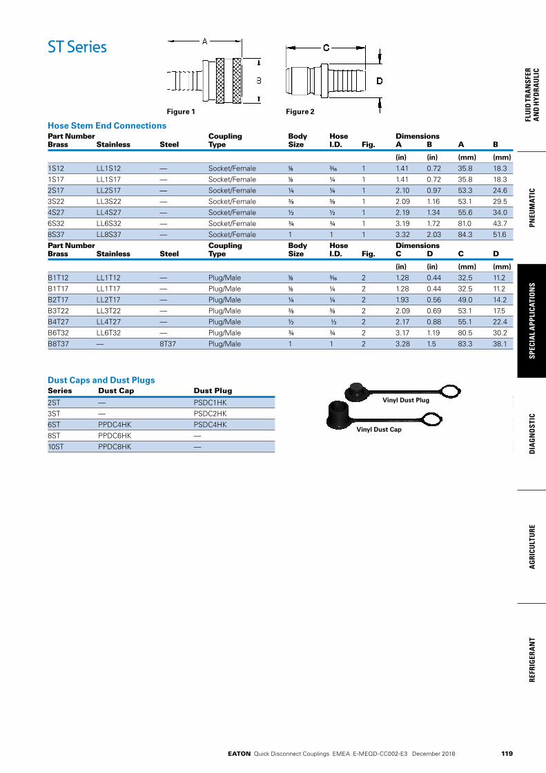
119
PNEU
MAT
ICSP
ECIA
L A
PPLI
CATI
ON
SD
IAG
NO
STIC
AG
RICU
LTU
RERE
FRIG
ERA
NT
FLU
ID T
RAN
SFER
AN
D H
YDRA
ULI
C
EATON Quick Disconnect Couplings EMEA E-MEQD-CC002-E3 December 2018
ST Series
Hose Stem End ConnectionsPart Number Coupling Body Hose Dimensions Brass Stainless Steel Type Size I.D. Fig. A B A B
(in) (in) (mm) (mm)
1S12 LL1S12 — Socket/Female 1/8 3/16 1 1.41 0.72 35.8 18.31S17 LL1S17 — Socket/Female 1/8 1/4 1 1.41 0.72 35.8 18.32S17 LL2S17 — Socket/Female 1/4 1/4 1 2.10 0.97 53.3 24.63S22 LL3S22 — Socket/Female 3/8 3/8 1 2.09 1.16 53.1 29.54S27 LL4S27 — Socket/Female 1/2 1/2 1 2.19 1.34 55.6 34.06S32 LL6S32 — Socket/Female ¾ ¾ 1 3.19 1.72 81.0 43.78S37 LL8S37 — Socket/Female 1 1 1 3.32 2.03 84.3 51.6Part Number Coupling Body Hose Dimensions Brass Stainless Steel Type Size I.D. Fig. C D C D
(in) (in) (mm) (mm)
B1T12 LL1T12 — Plug/Male 1/8 3/16 2 1.28 0.44 32.5 11.2B1T17 LL1T17 — Plug/Male 1/8 1/4 2 1.28 0.44 32.5 11.2B2T17 LL2T17 — Plug/Male 1/4 1/4 2 1.93 0.56 49.0 14.2B3T22 LL3T22 — Plug/Male 3/8 3/8 2 2.09 0.69 53.1 17.5B4T27 LL4T27 — Plug/Male 1/2 1/2 2 2.17 0.88 55.1 22.4B6T32 LL6T32 — Plug/Male ¾ ¾ 2 3.17 1.19 80.5 30.2B8T37 — 8T37 Plug/Male 1 1 2 3.28 1.5 83.3 38.1
Dust Caps and Dust Plugs Series Dust Cap Dust Plug
2ST — PSDC1HK 3ST — PSDC2HK 6ST PPDC4HK PSDC4HK 8ST PPDC6HK — 10ST PPDC8HK —
Vinyl Dust Cap
Vinyl Dust Plug
Figure 1 Figure 2

120
FLUID
TRAN
SFERA
ND
HYD
RAU
LICPN
EUM
ATICSPECIA
L APPLICATIO
NS
DIA
GN
OSTIC
AG
RICULTU
REREFRIG
ERAN
T
EATON Quick Disconnect Couplings EMEA E-MEQD-CC002-E3 December 2018
• Proprietary profile• Full flow pull-to-connect couplings• Ball-locking• Excellent flow performance
• Standard body material: Zinc trivalent plated steel
• Optional dust caps and plugs (made of anodized aluminum)
• Standard seal material: NBR, FKM, EPDM
Product Features
L7000 SeriesFull Flow (Steel)
Applications & Markets• Fluid Transfer Lines• Refrigerant Circuits• Applications where
maximum flow capacity is required
Physical Characteristics
Body Size
Nominal Flow Diameter
Max. Operating Pressure (connected)*Non hazardous liquids & gases in Group 2
Hazardous liquids & gases in Group 1
(in) (mm) bar (psi) bar (psi)
8 1,000 14,500 1,000 14,500
¼ 10 700 10,150 700 10,150
12 600 8,700 600 8,700
½ 15 500 7,250 500 7,250
¾ 20 400 5,800 400 5,800
1 25 300 4,350 300 4,350
1¼ 33 200 2,900 30 435
1½ 40 150 2,175 24 345
2 50 100 1,450 19 275
Seal Elastomer Data* Seal Elastomer Max. Operation Temperature Range
NBR (Nitrile) -20°C +100°C/-4°F +212°F
FKM (Fluorocarbon) -20°C +200°C/-4°F +392°F
EPDM (Ethylene-Propylene)** -40°C +150°C/-40°F +302°F
*For reference only, based on Eaton recommended temperatures. ** In accordance with NF L 17-241 or NAS 1613 rev. 5, depending on size.
Contact Eaton technical support for further information on fluid compatibility.
Couplings with nominal diameters up to and including 25 mm are designed and manufactured under Article 4.3 of the European Pressure Equipment Directive PED 2014/68/EU. Couplings with nominal diameters greater than 25 mm are designed and manufactured in accor-dance with the stipulations of Module A of the European Pressure Equipment Directive PED 2014/68/EU. They should not be used to convey unstable gases.*Group 1 = Hazardous media / Group 2 = Other media
Flow Data
The nominal flow diameter of the coupling has no impact on pressure drop, as it is wider than the circuit diameter.
European Pressure Equipment Directive*
Eaton’s L7000 Series steel quick disconnect coupling is a full-flow coupling with a rugged construction. Similar to the Eaton H5000 Series, the heat treatment and hardened materials give the coupling excellent resistance to mechanical and hy-draulic demands. It is suited for applications where maximum flow capacity is a requirement and valving is not needed.
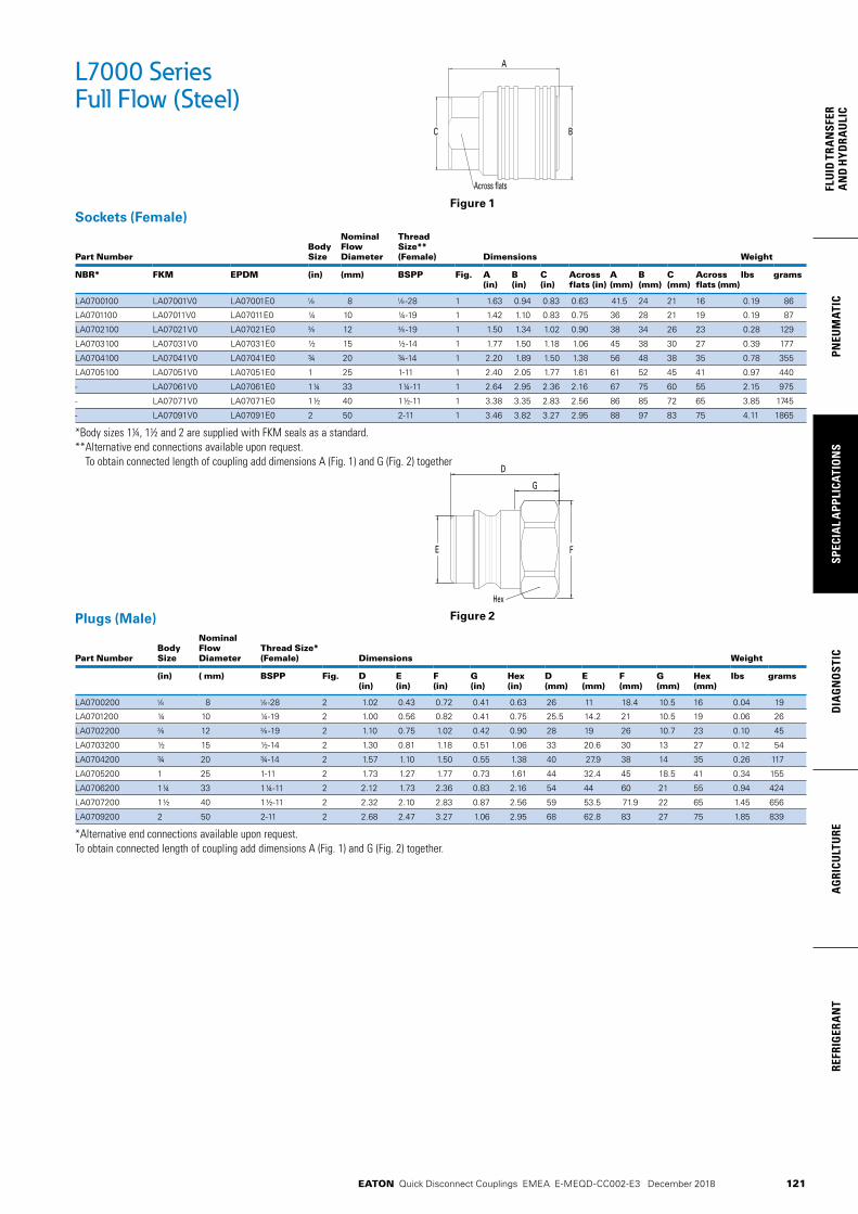
121
PNEU
MAT
ICSP
ECIA
L A
PPLI
CATI
ON
SD
IAG
NO
STIC
AG
RICU
LTU
RERE
FRIG
ERA
NT
FLU
ID T
RAN
SFER
AN
D H
YDRA
ULI
C
EATON Quick Disconnect Couplings EMEA E-MEQD-CC002-E3 December 2018
L7000 SeriesFull Flow (Steel)
Sockets (Female)
Part NumberBody Size
Nominal Flow Diameter
Thread Size** (Female) Dimensions Weight
NBR* FKM EPDM (in) (mm) BSPP Fig. A (in)
B (in)
C (in)
Across flats (in)
A (mm)
B (mm)
C (mm)
Across flats (mm)
lbs grams
LA0700100 LA07001V0 LA07001E0 8 -28 1 1.63 0.94 0.83 0.63 41.5 24 21 16 0.19 86
LA0701100 LA07011V0 LA07011E0 ¼ 10 ¼-19 1 1.42 1.10 0.83 0.75 36 28 21 19 0.19 87
LA0702100 LA07021V0 LA07021E0 12 -19 1 1.50 1.34 1.02 0.90 38 34 26 23 0.28 129
LA0703100 LA07031V0 LA07031E0 ½ 15 ½-14 1 1.77 1.50 1.18 1.06 45 38 30 27 0.39 177
LA0704100 LA07041V0 LA07041E0 ¾ 20 ¾-14 1 2.20 1.89 1.50 1.38 56 48 38 35 0.78 355
LA0705100 LA07051V0 LA07051E0 1 25 1-11 1 2.40 2.05 1.77 1.61 61 52 45 41 0.97 440
- LA07061V0 LA07061E0 1¼ 33 1¼-11 1 2.64 2.95 2.36 2.16 67 75 60 55 2.15 975
- LA07071V0 LA07071E0 1½ 40 1½-11 1 3.38 3.35 2.83 2.56 86 85 72 65 3.85 1745
- LA07091V0 LA07091E0 2 50 2-11 1 3.46 3.82 3.27 2.95 88 97 83 75 4.11 1865
*Body sizes 1¼, 1½ and 2 are supplied with FKM seals as a standard.** Alternative end connections available upon request.
To obtain connected length of coupling add dimensions A (Fig. 1) and G (Fig. 2) together
Plugs (Male)
Part NumberBody Size
Nominal Flow Diameter
Thread Size* (Female) Dimensions Weight
(in) ( mm) BSPP Fig. D (in)
E (in)
F (in)
G (in)
Hex (in)
D (mm)
E (mm)
F (mm)
G (mm)
Hex (mm)
lbs grams
LA0700200 8 -28 2 1.02 0.43 0.72 0.41 0.63 26 11 18.4 10.5 16 0.04 19
LA0701200 ¼ 10 ¼-19 2 1.00 0.56 0.82 0.41 0.75 25.5 14.2 21 10.5 19 0.06 26
LA0702200 12 -19 2 1.10 0.75 1.02 0.42 0.90 28 19 26 10.7 23 0.10 45
LA0703200 ½ 15 ½-14 2 1.30 0.81 1.18 0.51 1.06 33 20.6 30 13 27 0.12 54
LA0704200 ¾ 20 ¾-14 2 1.57 1.10 1.50 0.55 1.38 40 27.9 38 14 35 0.26 117
LA0705200 1 25 1-11 2 1.73 1.27 1.77 0.73 1.61 44 32.4 45 18.5 41 0.34 155
LA0706200 1¼ 33 1¼-11 2 2.12 1.73 2.36 0.83 2.16 54 44 60 21 55 0.94 424
LA0707200 1½ 40 1½-11 2 2.32 2.10 2.83 0.87 2.56 59 53.5 71.9 22 65 1.45 656
LA0709200 2 50 2-11 2 2.68 2.47 3.27 1.06 2.95 68 62.8 83 27 75 1.85 839
*Alternative end connections available upon request.To obtain connected length of coupling add dimensions A (Fig. 1) and G (Fig. 2) together.
G
D
FE
Hex
A
BC
Across flats
Figure 1
Figure 2
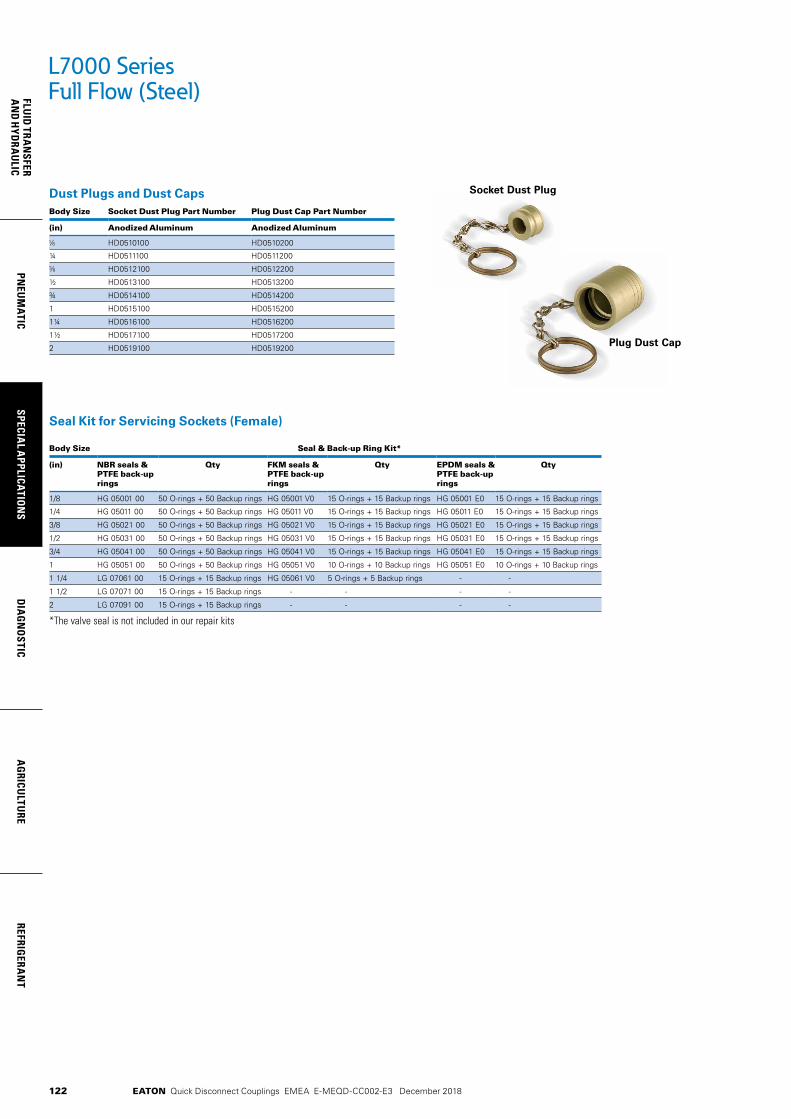
122
FLUID
TRAN
SFERA
ND
HYD
RAU
LICPN
EUM
ATICSPECIA
L APPLICATIO
NS
DIA
GN
OSTIC
AG
RICULTU
REREFRIG
ERAN
T
EATON Quick Disconnect Couplings EMEA E-MEQD-CC002-E3 December 2018
Seal Kit for Servicing Sockets (Female)
Body Size Seal & Back-up Ring Kit*
(in) NBR seals & PTFE back-up rings
Qty FKM seals & PTFE back-up rings
Qty EPDM seals & PTFE back-up rings
Qty
1/8 HG 05001 00 50 O-rings + 50 Backup rings HG 05001 V0 15 O-rings + 15 Backup rings HG 05001 E0 15 O-rings + 15 Backup rings
1/4 HG 05011 00 50 O-rings + 50 Backup rings HG 05011 V0 15 O-rings + 15 Backup rings HG 05011 E0 15 O-rings + 15 Backup rings
3/8 HG 05021 00 50 O-rings + 50 Backup rings HG 05021 V0 15 O-rings + 15 Backup rings HG 05021 E0 15 O-rings + 15 Backup rings
1/2 HG 05031 00 50 O-rings + 50 Backup rings HG 05031 V0 15 O-rings + 15 Backup rings HG 05031 E0 15 O-rings + 15 Backup rings
3/4 HG 05041 00 50 O-rings + 50 Backup rings HG 05041 V0 15 O-rings + 15 Backup rings HG 05041 E0 15 O-rings + 15 Backup rings
1 HG 05051 00 50 O-rings + 50 Backup rings HG 05051 V0 10 O-rings + 10 Backup rings HG 05051 E0 10 O-rings + 10 Backup rings
1 1/4 LG 07061 00 15 O-rings + 15 Backup rings HG 05061 V0 5 O-rings + 5 Backup rings - -
1 1/2 LG 07071 00 15 O-rings + 15 Backup rings - - - -
2 LG 07091 00 15 O-rings + 15 Backup rings - - - -
*The valve seal is not included in our repair kits
L7000 SeriesFull Flow (Steel)
Dust Plugs and Dust CapsBody Size Socket Dust Plug Part Number Plug Dust Cap Part Number
(in) Anodized Aluminum Anodized Aluminum
HD0510100 HD0510200
¼ HD0511100 HD0511200
HD0512100 HD0512200
½ HD0513100 HD0513200
¾ HD0514100 HD0514200
1 HD0515100 HD0515200
1¼ HD0516100 HD0516200
1½ HD0517100 HD0517200
2 HD0519100 HD0519200
Socket Dust Plug
Plug Dust Cap

123
PNEU
MAT
ICSP
ECIA
L A
PPLI
CATI
ON
SD
IAG
NO
STIC
AG
RICU
LTU
RERE
FRIG
ERA
NT
FLU
ID T
RAN
SFER
AN
D H
YDRA
ULI
C
EATON Quick Disconnect Couplings EMEA E-MEQD-CC002-E3 December 2018
Eaton’s L7000 Series brass quick disconnect coupling is a full-flow coupling suited for applications where maximum flow capacity is required and valving is not needed. Main-ly used in fluid transfer applications where stainless steel is not a requirement, it can vehicle a wide range of media and offers good corrosion resistance.
• Proprietary profile• Full flow pull-to-connect couplings• Ball-locking• Excellent flow performance
• Standard body material: Nickel-plated brass
• Optional dust caps and plugs (made of anodized aluminum)
• Standard seal material: NBR, FKM, EPDM
Product Features
L7000 SeriesFull Flow (Brass)
Physical CharacteristicsBody Size
Nominal Flow Diameter
Max. Operating Pressure (connected)*Liquids in Groups 1 and 2 Gases in Group 2
(in) (mm) bar (psi) bar (psi)
8 300 4,350 300 4,350
¼ 10 230 3,335 230 3,335
12 175 2,535 175 2,535
½ 15 150 2,175 150 2,175
¾ 20 125 1,810 125 1,810
1 25 100 1,450 100 1,450
1¼ 33 60 870 30 435
1½ 40 49 710 24 348
2 50 39 565 19 275
* Nominal diameters over 25 mm should not be used to convey gases in Group 1 (as per PED 2014/68/EU).
Seal Elastomer Data*
Seal Elastomer Max. Operation Temperature Range
NBR (Nitrile) -20°C +100°C/-4°F +212°F
FKM (Fluorocarbon) -20°C +200°C/-4°F +392°F
EPDM (Ethylene-Propylene)** -40°C +150°C/-40°F +302°F
*For reference only, based on Eaton recommended temperatures.** In accordance with NF L 17-241 or NAS 1613 rev. 5, depending on size.
Contact Eaton technical support for further information on fluid compatibility.
All couplings are designed and manufactured under Article 4.3 of the European Pressure Equipment Directive PED 2014/68/EU. Couplings with nominal diameters greater than 25 mm should not be used to convey gases in Group 1 (hazardous).* Group 1 = Hazardous media / Group 2 = Other media
European Pressure Equipment Directive*
Applications & Markets• Pressure Washing• Steam-Cleaning
Equipment• Fluid Transfer Lines• Refrigerant Circuits• Applications where
maximum flow capacity is required
Flow Data
The nominal flow diameter of the coupling has no impact on pressure drop, as it is wider than the circuit diameter.
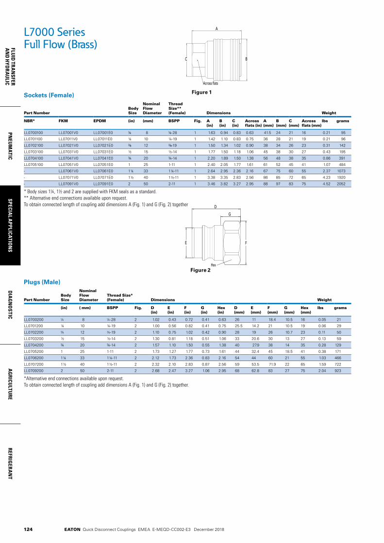
124
FLUID
TRAN
SFERA
ND
HYD
RAU
LICPN
EUM
ATICSPECIA
L APPLICATIO
NS
DIA
GN
OSTIC
AG
RICULTU
REREFRIG
ERAN
T
EATON Quick Disconnect Couplings EMEA E-MEQD-CC002-E3 December 2018
Sockets (Female)
Part NumberBody Size
Nominal Flow Diameter
Thread Size** (Female) Dimensions Weight
NBR* FKM EPDM (in) (mm) BSPP Fig. A (in)
B (in)
C (in)
Across flats (in)
A (mm)
B (mm)
C (mm)
Across flats (mm)
lbs grams
LL0700100 LL07001V0 LL07001E0 8 -28 1 1.63 0.94 0.83 0.63 41.5 24 21 16 0.21 95
LL0701100 LL07011V0 LL07011E0 ¼ 10 ¼-19 1 1.42 1.10 0.83 0.75 36 28 21 19 0.21 96
LL0702100 LL07021V0 LL07021E0 12 -19 1 1.50 1.34 1.02 0.90 38 34 26 23 0.31 142
LL0703100 LL07031V0 LL07031E0 ½ 15 ½-14 1 1.77 1.50 1.18 1.06 45 38 30 27 0.43 195
LL0704100 LL07041V0 LL07041E0 ¾ 20 ¾-14 1 2.20 1.89 1.50 1.38 56 48 38 35 0.86 391
LL0705100 LL07051V0 LL07051E0 1 25 1-11 1 2.40 2.05 1.77 1.61 61 52 45 41 1.07 484
- LL07061V0 LL07061E0 1¼ 33 1¼-11 1 2.64 2.95 2.36 2.16 67 75 60 55 2.37 1073
- LL07071V0 LL07071E0 1½ 40 1½-11 1 3.38 3.35 2.83 2.56 86 85 72 65 4.23 1920
- LL07091V0 LL07091E0 2 50 2-11 1 3.46 3.82 3.27 2.95 88 97 83 75 4.52 2052
* Body sizes 1¼, 1½ and 2 are supplied with FKM seals as a standard.** Alternative end connections available upon request.To obtain connected length of coupling add dimensions A (Fig. 1) and G (Fig. 2) together
G
D
FE
Hex
A
BC
Across flats
L7000 SeriesFull Flow (Brass)
Figure 1
Figure 2
Plugs (Male)
Part NumberBody Size
Nominal Flow Diameter
Thread Size* (Female) Dimensions Weight
(in) ( mm) BSPP Fig. D (in)
E (in)
F (in)
G (in)
Hex (in)
D (mm)
E (mm)
F (mm)
G (mm)
Hex (mm)
lbs grams
LL0700200 8 -28 2 1.02 0.43 0.72 0.41 0.63 26 11 18.4 10.5 16 0.05 21
LL0701200 ¼ 10 ¼-19 2 1.00 0.56 0.82 0.41 0.75 25.5 14.2 21 10.5 19 0.06 29
LL0702200 12 -19 2 1.10 0.75 1.02 0.42 0.90 28 19 26 10.7 23 0.11 50
LL0703200 ½ 15 ½-14 2 1.30 0.81 1.18 0.51 1.06 33 20.6 30 13 27 0.13 59
LL0704200 ¾ 20 ¾-14 2 1.57 1.10 1.50 0.55 1.38 40 27.9 38 14 35 0.28 129
LL0705200 1 25 1-11 2 1.73 1.27 1.77 0.73 1.61 44 32.4 45 18.5 41 0.38 171
LL0706200 1¼ 33 1¼-11 2 2.12 1.73 2.36 0.83 2.16 54 44 60 21 55 1.03 466
LL0707200 1½ 40 1½-11 2 2.32 2.10 2.83 0.87 2.56 59 53.5 71.9 22 65 1.59 722
LL0709200 2 50 2-11 2 2.68 2.47 3.27 1.06 2.95 68 62.8 83 27 75 2.04 923
*Alternative end connections available upon request.To obtain connected length of coupling add dimensions A (Fig. 1) and G (Fig. 2) together.
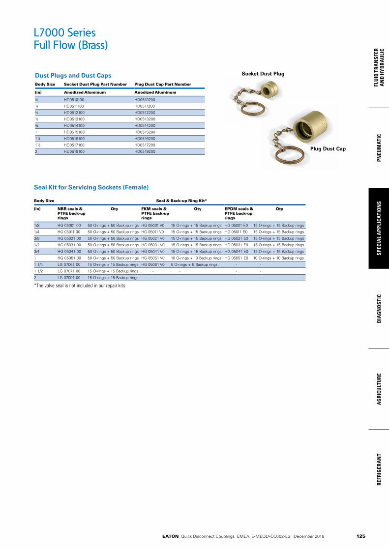
125
PNEU
MAT
ICSP
ECIA
L A
PPLI
CATI
ON
SD
IAG
NO
STIC
AG
RICU
LTU
RERE
FRIG
ERA
NT
FLU
ID T
RAN
SFER
AN
D H
YDRA
ULI
C
EATON Quick Disconnect Couplings EMEA E-MEQD-CC002-E3 December 2018
Seal Kit for Servicing Sockets (Female)
Body Size Seal & Back-up Ring Kit*
(in) NBR seals & PTFE back-up rings
Qty FKM seals & PTFE back-up rings
Qty EPDM seals & PTFE back-up rings
Qty
1/8 HG 05001 00 50 O-rings + 50 Backup rings HG 05001 V0 15 O-rings + 15 Backup rings HG 05001 E0 15 O-rings + 15 Backup rings
1/4 HG 05011 00 50 O-rings + 50 Backup rings HG 05011 V0 15 O-rings + 15 Backup rings HG 05011 E0 15 O-rings + 15 Backup rings
3/8 HG 05021 00 50 O-rings + 50 Backup rings HG 05021 V0 15 O-rings + 15 Backup rings HG 05021 E0 15 O-rings + 15 Backup rings
1/2 HG 05031 00 50 O-rings + 50 Backup rings HG 05031 V0 15 O-rings + 15 Backup rings HG 05031 E0 15 O-rings + 15 Backup rings
3/4 HG 05041 00 50 O-rings + 50 Backup rings HG 05041 V0 15 O-rings + 15 Backup rings HG 05041 E0 15 O-rings + 15 Backup rings
1 HG 05051 00 50 O-rings + 50 Backup rings HG 05051 V0 10 O-rings + 10 Backup rings HG 05051 E0 10 O-rings + 10 Backup rings
1 1/4 LG 07061 00 15 O-rings + 15 Backup rings HG 05061 V0 5 O-rings + 5 Backup rings - -
1 1/2 LG 07071 00 15 O-rings + 15 Backup rings - - - -
2 LG 07091 00 15 O-rings + 15 Backup rings - - - -
*The valve seal is not included in our repair kits
Dust Plugs and Dust CapsBody Size Socket Dust Plug Part Number Plug Dust Cap Part Number
(in) Anodized Aluminum Anodized Aluminum
HD0510100 HD0510200
¼ HD0511100 HD0511200
HD0512100 HD0512200
½ HD0513100 HD0513200
¾ HD0514100 HD0514200
1 HD0515100 HD0515200
1¼ HD0516100 HD0516200
1½ HD0517100 HD0517200
2 HD0519100 HD0519200
Socket Dust Plug
Plug Dust Cap
L7000 SeriesFull Flow (Brass)

126
FLUID
TRAN
SFERA
ND
HYD
RAU
LICPN
EUM
ATICSPECIA
L APPLICATIO
NS
DIA
GN
OSTIC
AG
RICULTU
REREFRIG
ERAN
T
EATON Quick Disconnect Couplings EMEA E-MEQD-CC002-E3 December 2018
Eaton’s L7000 Series stainless steel quick disconnect coupling is a full-flow coupling suited for applications where maximum flow capacity is required and valving is not needed. Mainly used in fluid transfer applications and offers excellent corrosion resistance.
• Proprietary profile• Full flow pull-to-connect couplings• Ball-locking• Excellent flow performance• Standard body material: AISI 316L Stainless steel• Optional dust caps and plugs (made of anodized aluminum)• Standard seal material: FKM, EPDM
Product Features
L7000 SeriesFull Flow (Stainless Steel)
Applications & Markets• Pressure Washing• Steam-cleaning
Equipment• Fluid Transfer Lines• Refrigerant Circuits• Applications where
maximum flow capacity is required
Physical Characteristics
Max. Operating Pressure (connected)
Body SizeNominal Flow Diameter
Non hazardous liquids & gases Group 2
Non hazardous liquids & gases Group 1
(in) (mm) (bar) (psi) (bar) (psi)
8 300 4,350 300 4,350
¼ 10 230 3,335 230 3,335
12 175 3,535 175 3,535
½ 15 150 2,175 150 2,175
¾ 20 125 1,810 125 1,810
1 25 100 1,450 100 1,450
1¼ 33 100 1,450 100 1,450
1½ 40 75 1,085 38 550
2 50 40 580 28 405
Seal Elastomer Data*
Seal Elastomer Max. Operation Temperature Range
FKM (Fluorocarbon) -20°C +200°C/-4°F +392°F
EPDM (Ethylene-Propylene)** -40°C +150°C/-40°F +302°F
*For reference only, based on Eaton recommended temperatures.** In accordance with NF L 17-241 or NAS 1613 rev. 5, depending on size.
Contact Eaton technical support for further information on fluid compatibility.
Flow Data
The nominal flow diameter of the coupling has no impact on pressure drop, as it is wider than the circuit diameter.
European Pressure Equipment Directive*
Couplings with nominal diameters up to and including 25 mm are designed and manufactured under Article 4.3 of the European Pressure Equipment Directive PED 2014/68/EU. Couplings with nominal diameters greater than 25 mm are designed and manufactured in accor-dance with the stipulations of Module A of the European Pressure Equipment Directive PED 2014/68/EU. They should not be used to convey unstable gases.*Group 1 = Hazardous media / Group 2 = Other media

127
PNEU
MAT
ICSP
ECIA
L A
PPLI
CATI
ON
SD
IAG
NO
STIC
AG
RICU
LTU
RERE
FRIG
ERA
NT
FLU
ID T
RAN
SFER
AN
D H
YDRA
ULI
C
EATON Quick Disconnect Couplings EMEA E-MEQD-CC002-E3 December 2018
L7000 Series Full Flow (Stainless Steel)
Sockets (Female)
Part NumberBody Size
Nominal Flow Diameter
Thread Size* (Female) Dimensions Weight
FKM EPDM (in) (mm) BSPP Fig. A (in)
B (in)
C (in)
Across flats (in)
A (mm)
B (mm)
C (mm)
Across flats (mm)
lbs grams
LZ07001V0 LZ07001E0 8 -28 1 1.63 0.94 0.83 0.63 41.5 24 21 16 0.19 86
LZ07011V0 LZ07011E0 ¼ 10 ¼-19 1 1.42 1.10 0.83 0.75 36 28 21 19 0.19 87
LZ07021V0 LZ07021E0 12 -19 1 1.50 1.34 1.02 0.90 38 34 26 23 0.28 129
LZ07031V0 LZ07031E0 ½ 15 ½-14 1 1.77 1.50 1.18 1.06 45 38 30 27 0.39 177
LZ07041V0 LZ07041E0 ¾ 20 ¾-14 1 2.20 1.89 1.50 1.38 56 48 38 35 0.78 355
LZ07051V0 LZ07051E0 1 25 1-11 1 2.40 2.05 1.77 1.61 61 52 45 41 0.97 440
LZ07061V0 LZ07061E0 1¼ 33 1¼-11 1 2.64 2.95 2.36 2.16 67 75 60 55 2.15 975
LZ07071V0 LZ07071E0 1½ 40 1½-11 1 3.38 3.35 2.83 2.56 86 85 72 65 3.85 1745
LZ07091V0 LZ07091E0 2 50 2-11 1 3.46 3.82 3.27 2.95 88 97 83 75 4.11 1865
*Alternative end connections available upon request.To obtain connected length of coupling add dimensions A (Fig. 1) and G (Fig. 2) together
Plugs (Male)
Part NumberBody Size
Nominal Flow Diameter
Thread Size* (Female) Dimensions Weight
(in) (mm) BSPP Fig. D (in)
E (in)
F (in)
G (in)
Hex (in)
D (mm)
E (mm)
F (mm)
G (mm)
Hex (mm)
lbs grams
LZ0700200 8 -28 2 1.02 0.43 0.72 0.41 0.63 26 11.0 18.4 10.5 16 0.04 19
LZ0701200 ¼ 10 ¼-19 2 1.00 0.56 0.82 0.41 0.75 25.5 14.2 21 10.5 19 0.06 26
LZ0702200 12 -19 2 1.10 0.75 1.02 0.42 0.90 28 19.0 26 10.7 23 0.10 45
LZ0703200 ½ 15 ½-14 2 1.30 0.81 1.18 0.51 1.06 33 20.6 30 13 27 0.12 54
LZ0704200 ¾ 20 ¾-14 2 1.57 1.10 1.50 0.55 1.38 40 27.9 38 14 35 0.26 117
LZ0705200 1 25 1-11 2 1.73 1.27 1.77 0.73 1.61 44 32.4 45 18.5 41 0.34 155
LZ0706200 1¼ 33 1¼-11 2 2.12 1.73 2.36 0.83 2.16 54 44.0 60 21 55 0.94 424
LZ0707200 1½ 40 1½-11 2 2.32 2.10 2.83 0.87 2.56 59 53.5 71.9 22 65 1.45 656
LZ0709200 2 50 2-11 2 2.68 2.47 3.27 1.06 2.95 68 62.8 83 27 75 1.85 839
*Alternative end connections available upon request.To obtain connected length of coupling add dimensions A (Fig. 1) and G (Fig. 2) together.
G
D
FE
Hex
A
BC
Across flats
Figure 1
Figure 2
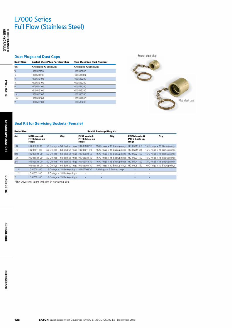
128
FLUID
TRAN
SFERA
ND
HYD
RAU
LICPN
EUM
ATICSPECIA
L APPLICATIO
NS
DIA
GN
OSTIC
AG
RICULTU
REREFRIG
ERAN
T
EATON Quick Disconnect Couplings EMEA E-MEQD-CC002-E3 December 2018
Seal Kit for Servicing Sockets (Female)
Body Size Seal & Back-up Ring Kit*
(in) NBR seals & PTFE back-up rings
Qty FKM seals & PTFE back-up rings
Qty EPDM seals & PTFE back-up rings
Qty
1/8 HG 05001 00 50 O-rings + 50 Backup rings HG 05001 V0 15 O-rings + 15 Backup rings HG 05001 E0 15 O-rings + 15 Backup rings
1/4 HG 05011 00 50 O-rings + 50 Backup rings HG 05011 V0 15 O-rings + 15 Backup rings HG 05011 E0 15 O-rings + 15 Backup rings
3/8 HG 05021 00 50 O-rings + 50 Backup rings HG 05021 V0 15 O-rings + 15 Backup rings HG 05021 E0 15 O-rings + 15 Backup rings
1/2 HG 05031 00 50 O-rings + 50 Backup rings HG 05031 V0 15 O-rings + 15 Backup rings HG 05031 E0 15 O-rings + 15 Backup rings
3/4 HG 05041 00 50 O-rings + 50 Backup rings HG 05041 V0 15 O-rings + 15 Backup rings HG 05041 E0 15 O-rings + 15 Backup rings
1 HG 05051 00 50 O-rings + 50 Backup rings HG 05051 V0 10 O-rings + 10 Backup rings HG 05051 E0 10 O-rings + 10 Backup rings
1 1/4 LG 07061 00 15 O-rings + 15 Backup rings HG 05061 V0 5 O-rings + 5 Backup rings - -
1 1/2 LG 07071 00 15 O-rings + 15 Backup rings - - - -
2 LG 07091 00 15 O-rings + 15 Backup rings - - - -
*The valve seal is not included in our repair kits
L7000 SeriesFull Flow (Stainless Steel)
Dust Plugs and Dust CapsBody Size Socket Dust Plug Part Number Plug Dust Cap Part Number
(in) Anodized Aluminum Anodized Aluminum
HD0510100 HD0510200
¼ HD0511100 HD0511200
HD0512100 HD0512200
½ HD0513100 HD0513200
¾ HD0514100 HD0514200
1 HD0515100 HD0515200
1¼ HD0516100 HD0516200
1½ HD0517100 HD0517200
2 HD0519100 HD0519200
Socket dust plug
Plug dust cap
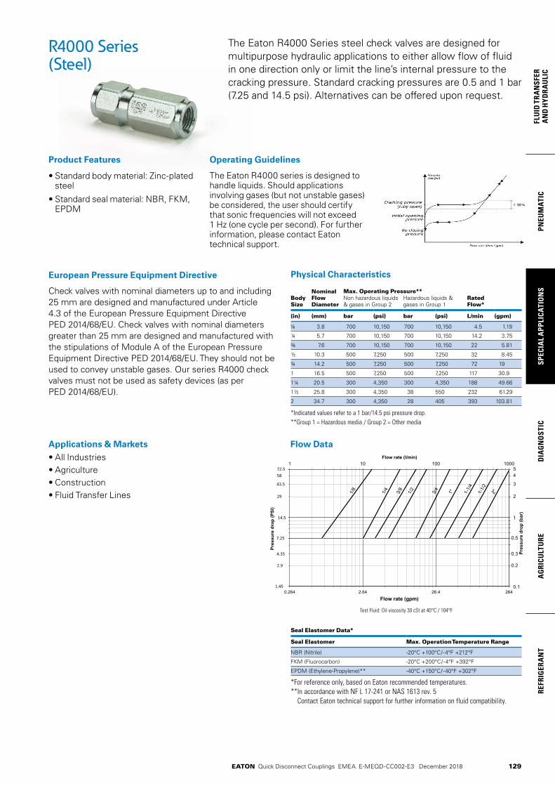
129
PNEU
MAT
ICSP
ECIA
L A
PPLI
CATI
ON
SD
IAG
NO
STIC
AG
RICU
LTU
RERE
FRIG
ERA
NT
FLU
ID T
RAN
SFER
AN
D H
YDRA
ULI
C
EATON Quick Disconnect Couplings EMEA E-MEQD-CC002-E3 December 2018
• Standard body material: Zinc-plated steel
• Standard seal material: NBR, FKM, EPDM
Physical Characteristics
Nominal Flow Diameter
Max. Operating Pressure**Body Size
Non hazardous liquids & gases in Group 2
Hazardous liquids & gases in Group 1
Rated Flow*
(in) (mm) bar (psi) bar (psi) L/min (gpm)
3.8 700 10,150 700 10,150 4.5 1.19
¼ 5.7 700 10,150 700 10,150 14.2 3.75
7.6 700 10,150 700 10,150 22 5.81
½ 10.3 500 7,250 500 7,250 32 8.45
¾ 14.2 500 7,250 500 7,250 72 19
1 16.5 500 7,250 500 7,250 117 30.9
1¼ 20.5 300 4,350 300 4,350 188 49.66
1½ 25.8 300 4,350 38 550 232 61.29
2 34.7 300 4,350 28 405 393 103.81
*Indicated values refer to a 1 bar/14.5 psi pressure drop.**Group 1 = Hazardous media / Group 2 = Other media
The Eaton R4000 Series steel check valves are designed for multipurpose hydraulic applications to either allow flow of fluid in one direction only or limit the line’s internal pressure to the cracking pressure. Standard cracking pressures are 0.5 and 1 bar (7.25 and 14.5 psi). Alternatives can be offered upon request.
Seal Elastomer Data*
Seal Elastomer Max. Operation Temperature Range
NBR (Nitrile) -20°C +100°C/-4°F +212°F
FKM (Fluorocarbon) -20°C +200°C/-4°F +392°F
EPDM (Ethylene-Propylene)** -40°C +150°C/-40°F +302°F
*For reference only, based on Eaton recommended temperatures.** In accordance with NF L 17-241 or NAS 1613 rev. 5
Contact Eaton technical support for further information on fluid compatibility.
Check valves with nominal diameters up to and including 25 mm are designed and manufactured under Article 4.3 of the European Pressure Equipment Directive PED 2014/68/EU. Check valves with nominal diameters greater than 25 mm are designed and manufactured with the stipulations of Module A of the European Pressure Equipment Directive PED 2014/68/EU. They should not be used to convey unstable gases. Our series R4000 check valves must not be used as safety devices (as per PED 2014/68/EU).
European Pressure Equipment Directive
Applications & Markets• All Industries• Agriculture• Construction • Fluid Transfer Lines
0.264 2.64 26.4 0.1
1
0.5
0.3
0.2
54
3
1 10 100 1000
Flow rate (gpm)
Pres
sure
dro
p (P
SI)
Pres
sure
dro
p (b
ar)
Flow rate (l/min)
72.5
1.45
14.5
43.5
4.35
7.25
58
29
2.9
2
264
1/8
1/4
3/8
1/2
3/4
1" 2"1-1/
2
1-1/
4
Test Fluid: Oil viscosity 30 cSt at 40°C / 104°F
R4000 Series(Steel)
Operating GuidelinesProduct Features
The Eaton R4000 series is designed to handle liquids. Should applications involving gases (but not unstable gases) be considered, the user should certify that sonic frequencies will not exceed 1 Hz (one cycle per second). For further information, please contact Eaton technical support.
Flow Data

130
FLUID
TRAN
SFERA
ND
HYD
RAU
LICPN
EUM
ATICSPECIA
L APPLICATIO
NS
DIA
GN
OSTIC
AG
RICULTU
REREFRIG
ERAN
T
EATON Quick Disconnect Couplings EMEA E-MEQD-CC002-E3 December 2018
R4000 Series(Steel)
Cracking Pressure 0.5 bar (7.25 psi)
Part Number Body Size
Nominal Flow Diameter
Thread Size** (Female) Dimensions Weight
NBR* FKM EPDM (in) (mm) BSPP Fig. A (in)
B (in)
Hex (in)
A (mm)
B (mm)
Hex (mm)
lbs grams
RA0400000 RA04000V0 RA04000E0 3.8 1 1.46 0.69 0.63 37 17.5 16 0.10 45
RA0401000 RA04010V0 RA04010E0 ¼ 5.7 ¼ 1 1.97 0.83 0.75 50 21 19 0.18 80
RA0402000 RA04020V0 RA04020E0 7.6 1 2.36 0.98 0.90 60 25 23 0.29 130
RA0403000 RA04030V0 RA04030E0 ½ 10.3 ½ 1 2.75 1.15 1.06 70 29.2 27 0.44 200
RA0404000 RA04040V0 RA04040E0 ¾ 14.2 ¾ 1 3.38 1.50 1.38 86 38 35 0.93 420
RA0405000 RA04050V0 RA04050E0 1 16.5 1 1 3.94 1.77 1.61 100 45 41 1.41 640
-- RA04060V0 RA04060E0 1¼ 20.5 1¼ 1 5.12 2.40 2.16 130 61 55 3.46 1570
-- RA04070V0 RA04070E0 1½ 25.8 1½ 1 5.31 2.83 2.56 135 72 65 5.16 2340
-- RA04090V0 RA04090E0 2 34.7 2 1 5.90 3.30 2.95***150 84 75*** 6.57 2980
*Body size 1¼, 1½ and 2 are supplied with FKM seals as a standard.**Alternative end connections available upon request. depending on size (please contact Eaton technical support).***Across flat dimension.
Cracking Pressure 1 bar (14.5 psi)
Part Number Body Size
Nominal Flow Diameter
Thread Size** (Female) Dimensions Weight
NBR* FKM EPDM (in) (mm) BSPP Fig. A (in)
B (in)
Hex (in)
A (mm)
B (mm)
Hex (mm)
lbs grams
RA040000B RA04000VB RA04000EB 3.8 1 1.46 0.69 0.63 37 17.5 16 0.10 45
RA040100B RA04010VB RA04010EB ¼ 5.7 ¼ 1 1.97 0.83 0.75 50 21 19 0.18 80
RA040200B RA04020VB RA04020EB 7.6 1 2.36 0.98 0.90 60 25 23 0.29 130
RA040300B RA04030VB RA04030EB ½ 10.3 ½ 1 2.75 1.15 1.06 70 29.2 27 0.44 200
RA040400B RA04040VB RA04040EB ¾ 14.2 ¾ 1 3.38 1.50 1.38 86 38 35 0.93 420
RA040500B RA04050VB RA04050EB 1 16.5 1 1 3.94 1.77 1.61 100 45 41 1.41 640
-- RA04060VB RA04060EB 1¼ 20.5 1¼ 1 5.12 2.40 2.16 130 61 55 3.46 1570
-- RA04070VB RA04070EB 1½ 25.8 1½ 1 5.31 2.83 2.56 135 72 65 5.16 2340
-- RA04090VB RA04090EB 2 34.7 2 1 5.90 3.30 2.95***150 84 75*** 6.57 2980
*Body size 1¼, 1½ and 2 are supplied with FKM seals as a standard.**Alternative end connections available upon request. depending on size (please contact Eaton technical support).***Across flat dimension.
A
B
HexArrow shows flow direction
Figure 1
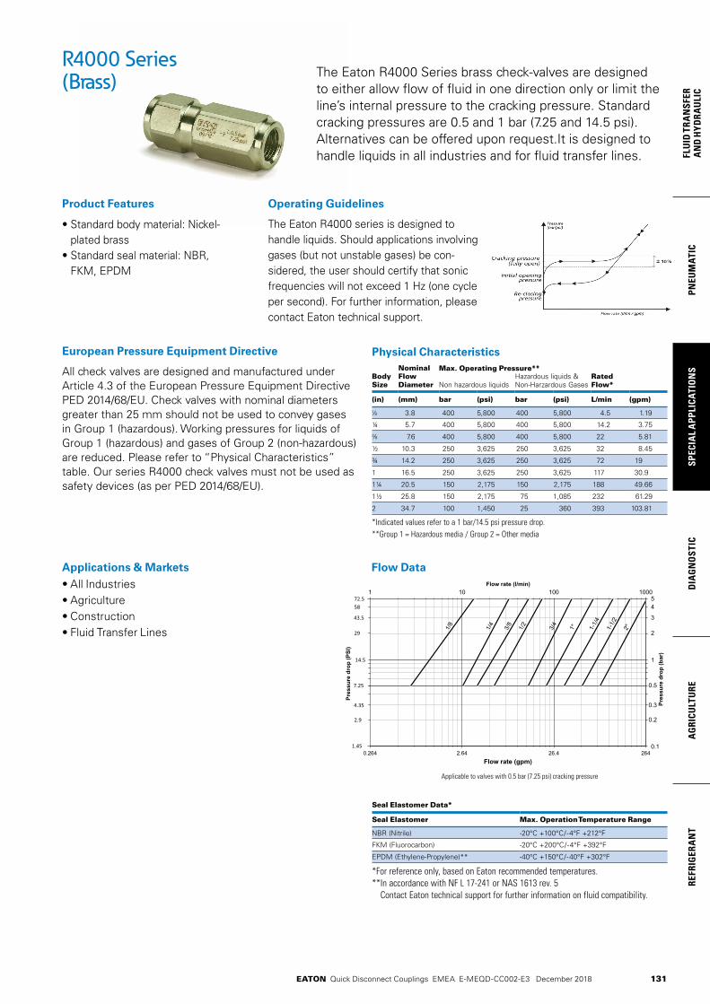
131
PNEU
MAT
ICSP
ECIA
L A
PPLI
CATI
ON
SD
IAG
NO
STIC
AG
RICU
LTU
RERE
FRIG
ERA
NT
FLU
ID T
RAN
SFER
AN
D H
YDRA
ULI
C
EATON Quick Disconnect Couplings EMEA E-MEQD-CC002-E3 December 2018
• Standard body material: Nickel- plated brass
• Standard seal material: NBR, FKM, EPDM
Physical Characteristics
Body Size
Nominal Flow Diameter
Max. Operating Pressure**Rated Flow*Non hazardous liquids
Hazardous liquids & Non-Harzardous Gases
(in) (mm) bar (psi) bar (psi) L/min (gpm)
3.8 400 5,800 400 5,800 4.5 1.19
¼ 5.7 400 5,800 400 5,800 14.2 3.75
7.6 400 5,800 400 5,800 22 5.81
½ 10.3 250 3,625 250 3,625 32 8.45
¾ 14.2 250 3,625 250 3,625 72 19
1 16.5 250 3,625 250 3,625 117 30.9
1¼ 20.5 150 2,175 150 2,175 188 49.66
1½ 25.8 150 2,175 75 1,085 232 61.29
2 34.7 100 1,450 25 360 393 103.81
*Indicated values refer to a 1 bar/14.5 psi pressure drop. **Group 1 = Hazardous media / Group 2 = Other media
The Eaton R4000 Series brass check-valves are designed to either allow flow of fluid in one direction only or limit the line’s internal pressure to the cracking pressure. Standard cracking pressures are 0.5 and 1 bar (7.25 and 14.5 psi). Alternatives can be offered upon request.It is designed to handle liquids in all industries and for fluid transfer lines.
Seal Elastomer Data*
Seal Elastomer Max. Operation Temperature Range
NBR (Nitrile) -20°C +100°C/-4°F +212°F
FKM (Fluorocarbon) -20°C +200°C/-4°F +392°F
EPDM (Ethylene-Propylene)** -40°C +150°C/-40°F +302°F
*For reference only, based on Eaton recommended temperatures.** In accordance with NF L 17-241 or NAS 1613 rev. 5
Contact Eaton technical support for further information on fluid compatibility.
All check valves are designed and manufactured under Article 4.3 of the European Pressure Equipment Directive PED 2014/68/EU. Check valves with nominal diameters greater than 25 mm should not be used to convey gases in Group 1 (hazardous). Working pressures for liquids of Group 1 (hazardous) and gases of Group 2 (non-hazardous) are reduced. Please refer to “Physical Characteristics” table. Our series R4000 check valves must not be used as safety devices (as per PED 2014/68/EU).
European Pressure Equipment Directive
Applications & Markets• All Industries• Agriculture• Construction• Fluid Transfer Lines
0.264 2.64 26.4 0.1
1
0.5
0.3
0.2
54
3
1 10 100 1000
Flow rate (gpm)
Pres
sure
dro
p (P
SI)
Pres
sure
dro
p (b
ar)
Flow rate (l/min)
72.5
1.45
14.5
43.5
4.35
7.25
58
29
2.9
2
264
1/8
1/4
3/8
1/2
3/4
1" 2"1-1/
2
1-1/
4
Applicable to valves with 0.5 bar (7.25 psi) cracking pressure
R4000 Series(Brass)
Product Features Operating Guidelines
The Eaton R4000 series is designed to handle liquids. Should applications involving gases (but not unstable gases) be con-sidered, the user should certify that sonic frequencies will not exceed 1 Hz (one cycle per second). For further information, please contact Eaton technical support.
Flow Data
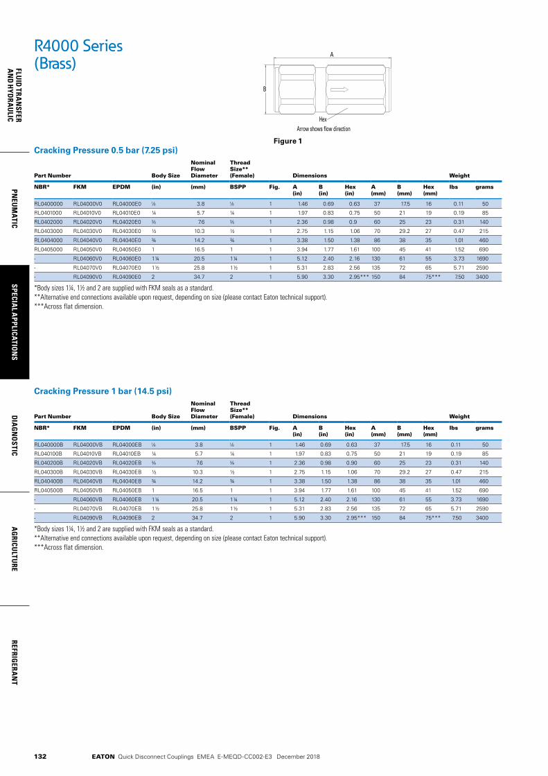
132
FLUID
TRAN
SFERA
ND
HYD
RAU
LICPN
EUM
ATICSPECIA
L APPLICATIO
NS
DIA
GN
OSTIC
AG
RICULTU
REREFRIG
ERAN
T
EATON Quick Disconnect Couplings EMEA E-MEQD-CC002-E3 December 2018
R4000 Series(Brass)
Cracking Pressure 0.5 bar (7.25 psi)
Part Number Body Size
Nominal Flow Diameter
Thread Size** (Female) Dimensions Weight
NBR* FKM EPDM (in) (mm) BSPP Fig. A (in)
B (in)
Hex (in)
A (mm)
B (mm)
Hex (mm)
lbs grams
RL0400000 RL04000V0 RL04000E0 3.8 1 1.46 0.69 0.63 37 17.5 16 0.11 50
RL0401000 RL04010V0 RL04010E0 ¼ 5.7 ¼ 1 1.97 0.83 0.75 50 21 19 0.19 85
RL0402000 RL04020V0 RL04020E0 7.6 1 2.36 0.98 0.9 60 25 23 0.31 140
RL0403000 RL04030V0 RL04030E0 ½ 10.3 ½ 1 2.75 1.15 1.06 70 29.2 27 0.47 215
RL0404000 RL04040V0 RL04040E0 ¾ 14.2 ¾ 1 3.38 1.50 1.38 86 38 35 1.01 460
RL0405000 RL04050V0 RL04050E0 1 16.5 1 1 3.94 1.77 1.61 100 45 41 1.52 690
- RL04060V0 RL04060E0 1¼ 20.5 1¼ 1 5.12 2.40 2.16 130 61 55 3.73 1690
- RL04070V0 RL04070E0 1½ 25.8 1½ 1 5.31 2.83 2.56 135 72 65 5.71 2590
- RL04090V0 RL04090E0 2 34.7 2 1 5.90 3.30 2.95*** 150 84 75*** 7.50 3400
*Body sizes 1¼, 1½ and 2 are supplied with FKM seals as a standard.**Alternative end connections available upon request, depending on size (please contact Eaton technical support).***Across flat dimension.
Cracking Pressure 1 bar (14.5 psi)
Part Number Body Size
Nominal Flow Diameter
Thread Size** (Female) Dimensions Weight
NBR* FKM EPDM (in) (mm) BSPP Fig. A (in)
B (in)
Hex (in)
A (mm)
B (mm)
Hex (mm)
lbs grams
RL040000B RL04000VB RL04000EB 3.8 1 1.46 0.69 0.63 37 17.5 16 0.11 50
RL040100B RL04010VB RL04010EB ¼ 5.7 ¼ 1 1.97 0.83 0.75 50 21 19 0.19 85
RL040200B RL04020VB RL04020EB 7.6 1 2.36 0.98 0.90 60 25 23 0.31 140
RL040300B RL04030VB RL04030EB ½ 10.3 ½ 1 2.75 1.15 1.06 70 29.2 27 0.47 215
RL040400B RL04040VB RL04040EB ¾ 14.2 ¾ 1 3.38 1.50 1.38 86 38 35 1.01 460
RL040500B RL04050VB RL04050EB 1 16.5 1 1 3.94 1.77 1.61 100 45 41 1.52 690
- RL04060VB RL04060EB 1¼ 20.5 1¼ 1 5.12 2.40 2.16 130 61 55 3.73 1690
- RL04070VB RL04070EB 1½ 25.8 1½ 1 5.31 2.83 2.56 135 72 65 5.71 2590
- RL04090VB RL04090EB 2 34.7 2 1 5.90 3.30 2.95*** 150 84 75*** 7.50 3400
*Body sizes 1¼, 1½ and 2 are supplied with FKM seals as a standard.**Alternative end connections available upon request, depending on size (please contact Eaton technical support).***Across flat dimension.
A
B
HexArrow shows flow direction
Figure 1
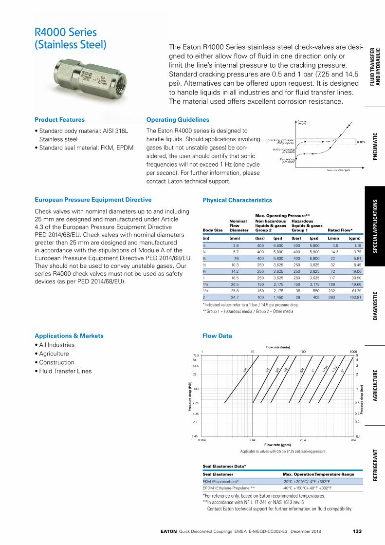
133
PNEU
MAT
ICSP
ECIA
L A
PPLI
CATI
ON
SD
IAG
NO
STIC
AG
RICU
LTU
RERE
FRIG
ERA
NT
FLU
ID T
RAN
SFER
AN
D H
YDRA
ULI
C
EATON Quick Disconnect Couplings EMEA E-MEQD-CC002-E3 December 2018
• Standard body material: AISI 316L Stainless steel
• Standard seal material: FKM, EPDM
Physical Characteristics
Max. Operating Pressure**
Body Size
Nominal Flow Diameter
Non hazardous liquids & gases Group 2
Hazardous liquids & gases Group 1 Rated Flow*
(in) (mm) (bar) (psi) (bar) (psi) L/min (gpm)
3.8 400 5,800 400 5,800 4.5 1.19
¼ 5.7 400 5,800 400 5,800 14.2 3.75
7.6 400 5,800 400 5,800 22 5.81
½ 10.3 250 3,625 250 3,625 32 8.45
¾ 14.2 250 3,625 250 3,625 72 19.00
1 16.5 250 3,625 250 3,625 117 30.90
1¼ 20.5 150 2,175 150 2,175 188 49.66
1½ 25.8 150 2,175 38 550 232 61.29
2 34.7 100 1,450 28 405 393 103.81
*Indicated values refer to a 1 bar / 14.5 psi pressure drop.**Group 1 = Hazardous media / Group 2 = Other media
Check valves with nominal diameters up to and including 25 mm are designed and manufactured under Article 4.3 of the European Pressure Equipment Directive PED 2014/68/EU. Check valves with nominal diameters greater than 25 mm are designed and manufactured in accordance with the stipulations of Module A of the European Pressure Equipment Directive PED 2014/68/EU. They should not be used to convey unstable gases. Our series R4000 check valves must not be used as safety devices (as per PED 2014/68/EU).
European Pressure Equipment Directive
Product Features
The Eaton R4000 Series stainless steel check-valves are desi-gned to either allow flow of fluid in one direction only or limit the line’s internal pressure to the cracking pressure. Standard cracking pressures are 0.5 and 1 bar (7.25 and 14.5 psi). Alternatives can be offered upon request. It is designed to handle liquids in all industries and for fluid transfer lines. The material used offers excellent corrosion resistance.
Seal Elastomer Data* Seal Elastomer Max. Operation Temperature Range
FKM (Fluorocarbon)* -20°C +200°C/-4°F +392°F
EPDM (Ethylene-Propylene)** -40°C +150°C/-40°F +302°F
*For reference only, based on Eaton recommended temperatures.** In accordance with NF L 17-241 or NAS 1613 rev. 5
Contact Eaton technical support for further information on fluid compatibility.
Applications & Markets• All Industries• Agriculture• Construction • Fluid Transfer Lines
0.264 2.64 26.4 0.1
1
0.5
0.3
0.2
54
3
1 10 100 1000
Flow rate (gpm)
Pres
sure
dro
p (P
SI)
Pres
sure
dro
p (b
ar)
Flow rate (l/min)
72.5
1.45
14.5
43.5
4.35
7.25
58
29
2.9
2
264
1/8
1/4
3/8
1/2
3/4
1" 2"1-1/
2
1-1/
4
Applicable to valves with 0.5 bar (7.25 psi) cracking pressure
R4000 Series(Stainless Steel)
Operating Guidelines
The Eaton R4000 series is designed to handle liquids. Should applications involving gases (but not unstable gases) be con-sidered, the user should certify that sonic frequencies will not exceed 1 Hz (one cycle per second). For further information, please contact Eaton technical support.
Flow Data
EATON Quick Disconnect Couplings EMEA E-MEQD-CC002-E4 December 2018134
FLUID
TRAN
SFERA
ND
HYD
RAU
LICPN
EUM
ATICSPECIA
L APPLICATIO
NS
DIA
GN
OSTIC
AG
RICULTU
REREFRIG
ERAN
T
R4000 Series(Stainless Steel)
Cracking Pressure 0.5 bar (7 psi)
Part Number Body Size
Nominal Flow Diameter
Thread Size* (Female) Dimensions Weight
FKM EPDM (in) (mm) BSPP Fig. A (in)
B (in)
Hex (in)
A (mm)
B (mm)
Hex (mm)
lbs grams
RZ04000V0 RZ04000E0 3.8 1 1.46 0.69 0.63 37 17.5 16 0.10 45
RZ04010V0 RZ04010E0 ¼ 5.7 ¼ 1 1.97 0.83 0.75 50 21 19 0.18 80
RZ04020V0 RZ04020E0 7.6 1 2.36 0.98 0.90 60 25 23 0.29 130
RZ04030V0 RZ04030E0 ½ 10.3 ½ 1 2.75 1.15 1.06 70 29.2 27 0.44 200
RZ04040V0 RZ04040E0 ¾ 14.2 ¾ 1 3.38 1.50 1.38 86 38 35 0.93 420
RZ04050V0 RZ04050E0 1 16.5 1 1 3.94 1.77 1.61 100 45 41 1.41 640
RZ04060V0 RZ04060E0 1¼ 20.5 1¼ 1 5.12 2.40 2.16 130 61 55 3.46 1570
RZ04070V0 RZ04070E0 1½ 25.8 1½ 1 5.31 2.83 2.56 135 72 65 5.16 2340
RZ04090V0 RZ04090E0 2 34.7 2 1 5.90 3.30 2.95** 150 84 75** 6.57 2980
*Alternative end connections available upon request, depending on size (please contact Eaton technical support).**Across flat dimension.
Cracking Pressure 1 bar (14.5 psi)
Part Number Body Size
Nominal Flow Diameter
Thread Size* (Female) Dimensions Weight
FKM EPDM (in) (mm) BSPP Fig. A (in)
B (in)
Hex (in)
A (mm)
B (mm)
Hex (mm)
lbs grams
RZ04000VB RZ04000EB 3.8 1 1.46 0.69 0.63 37 17.5 16 0.10 45
RZ04010VB RZ04010EB ¼ 5.7 ¼ 1 1.97 0.83 0.75 50 21 19 0.18 80
RZ04020VB RZ04020EB 7.6 1 2.36 0.98 0.90 60 25 23 0.29 130
RZ04030VB RZ04030EB ½ 10.3 ½ 1 2.75 1.15 1.06 70 29.2 27 0.44 200
RZ04040VB RZ04040EB ¾ 14.2 ¾ 1 3.38 1.50 1.38 86 38 35 0.93 420
RZ04050VB RZ04050EB 1 16.5 1 1 3.94 1.77 1.61 100 45 41 1.41 640
RZ04060VB RZ04060EB 1¼ 20.5 1¼ 1 5.12 2.40 2.16 130 61 55 3.46 1570
RZ04070VB RZ04070EB 1½ 25.8 1½ 1 5.31 2.83 2.56 135 72 65 5.16 2340
RZ04090VB RZ04090EB 2 34.7 2 1 5.90 3.30 2.95** 150 84 75** 6.57 2980
*Alternative end connections available upon request depending on size (please contact Eaton technical support).**Across flat dimension.
A
B
HexArrow shows flow direction
Figure 1
EATON Quick Disconnect Couplings EMEA E-MEQD-CC002-E4 December 2018 135
PNEU
MAT
ICSP
ECIA
L A
PPLI
CATI
ON
SD
IAG
NO
STIC
AG
RICU
LTU
RERE
FRIG
ERA
NT
FLU
ID T
RAN
SFER
AN
D H
YDRA
ULI
C
135
PNEU
MAT
ICSP
ECIA
L A
PPLI
CATI
ON
SD
IAG
NO
STIC
AG
RICU
LTU
RERE
FRIG
ERA
NT
FLU
ID T
RAN
SFER
AN
D H
YDRA
ULI
C
FD15 Series Oil Sampling Valve
Eaton’s FD15 Series Oil Sampling Valve is designed for in-line sampling of system fluids without system shutdown, usually in less than one minute, and without fluid contamination.
Product Features• Standard seal material:
Buna-N• Corrosion resistant plated
steel with brass internal components
• Operating Temperature Range: –65°F to +275°F (–53°C to +135°C)
Applications & Markets• Engine oil• Lubricating oil• Transmission fluid and
hydraulic fluids in mobile construction equipment, military vehicles, trucks and stationary equipment
• Minimum Burst Pressure: 12,000 psi
• Minimum Particle Restriction: 500 microns
• Maximum Torque to Operate: 10 in. lbs.
• FD15-1000-04 is qualified to the MIL-V-81940/2-1
Note: This valve is not intended for aerospace applications.
Operation• For best results, Eaton
FD15 Oil Sampling Valves should be installed in dynamic fluid lines in low pressure and return lines. If only one sampling point can be chosen, it should be in the return line, upstream of any return line filter. This will insure a representative sample of all components in the fluid system for their present condition.
Instructions1. Remove metal dustcover
on discharge port.2. Discharge approximately
200 ml of oil to flush valve by turning knurled knob 1/4 turn to the right. Dispose of this sample in the appropriate manner.
3. Locate clean oil sample bottle under discharge port. (Sample bottles are usually supplied by the oil analysis lab.)
4. Turn knurled knob 1/4 turn to the right until bottle is filled to the desired level. The knob can be backed off to throttle the rate of flow.
5. When bottle is filled let go of the knurled knob, the valve will close automatically. Replace metal dustcover wrench tight.
NotesAs required in MIL-V-81940/2-1 this valve’s flow rate is between 100 and 1500 milliliters per minute at pressures from 0–50 psi. (MIL-V-81940/2-1 applies only to pressures from 50–300 psi.)
The 1/4” NPTF version is qualified to MIL-V-81940/2-1 and its performance is representative of the other inlet port configurations listed above. QPL-81940-9 6-5-89

136
FLUID
TRAN
SFERA
ND
HYD
RAU
LICPN
EUM
ATICSPECIA
L APPLICATIO
NS
DIA
GN
OSTIC
AG
RICULTU
REREFRIG
ERAN
T
EATON Quick Disconnect Couplings EMEA E-MEQD-CC002-E4 December 2018
Dimensions (Male Pipe Thread)Part Number Sampling Port Dimensions Buna-N Type Size Thread Type Fig. A B C Hex 1 Hex 2 Hex 3
mm (in) mm (in) mm (in) mm (in) mm (in) mm (in)
FD15-1000-02 50-300 psi 1/8 1/8-27 Male Pipe Thread 1 61.5 (2.42) 25.4 (1.00) 33.0 (1.30) 17.5 (.69) 9.7 (.38) - -
FD15-1000-04 50-300 psi 1/4 1/4-18 Male Pipe Thread 1 65.0 (2.56) 25.4 (1.00) 33.0 (1.30) 17.5 (.69) 9.7 (.38) - -
Dimensions (Male SAE O-Ring Thread)Part Number Sampling Port Dimensions Buna-N Type Size Thread Type Fig. A B C Hex 1 Hex 2 Hex 3
mm (in) mm (in) mm (in) mm (in) mm (in) mm (in)
FD15-1002-04 50-300 psi 7/16 7/16-20 Male SAE O-Ring Thread 2 70.9 (2.79) 25.4 (1.00) 33.0 (1.30) 17.5 (.69) 9.7 (.38) 14.2 (.56)
Dimensions (Male Pipe Thread)Part Number Sampling Port Dimensions Buna-N Type Size Thread Type Fig. A B C Hex 1 Hex 2 Hex 3
mm (in) mm (in) mm (in) mm (in) mm (in) mm (in)
FD15-1026-04 0-50 psi 1/4 1/4-18 Male Pipe Thread 3 65.0 (2.56) 25.4 (1.00) 33.0 (1.30) 17.5 (.69) 9.7 (.38) - -
Dimensions Male SAE O-Ring Thread)Part Number Sampling Port Dimensions Buna-N Type Size Thread Type Fig. A B C Hex 1 Hex 2 Hex 3
mm (in) mm (in) mm (in) mm (in) mm (in) mm (in)
FD15-1025-04 0-50 psi 7/16 7/16-20 Male SAE O-Ring Thread 4 70.9 (2.79) 25.4 (1.00) 33.0 (1.30) 17.5 (.69) 9.7 (.38) 14.2 (.56)
Male Pipe Thread50-300 psi
Male SAE O-Ring Thread50-300 psi
Figure 1 Figure 2
Male Pipe Thread0-50 psi
Male SAE O-Ring Thread0-50 psi
Figure 3 Figure 4
FD15 Series Oil Sampling Valve

137
PNEU
MAT
ICSP
ECIA
L A
PPLI
CATI
ON
SD
IAG
NO
STIC
AG
RICU
LTU
RERE
FRIG
ERA
NT
FLU
ID T
RAN
SFER
AN
D H
YDRA
ULI
C
EATON Quick Disconnect Couplings EMEA E-MEQD-CC002-E4 December 2018
Figure 2
FD90 Series Diagnostic Coupling SAE J1502 Interchange
Eaton’s FD90 Series diagnostic coupling is designed to connect and disconnect pressure gauges to hydraulic systems, eliminating the need for permanent gauges. The maximum operating pressure is 7,000 psi.
Product Features• Automatic sleeve for one
hand push-to-connect operation
• Flush face valving provides minimal fluid loss and low air inclusion
• Self-sealing valve design allows connection and disconnection at 500 psi
• Broad range of end configurations for system accessibility
• Standard seal material: Buna-N
• Standard seal material: High resistance carbon steel with Zinc trivalent plating
Physical Characteristics Coupling Max. Operating Min. Burst Pressure Vacuum Rated Air Fluid Body Size Pressure Connected Connected Only Flow Inclusion Loss
(in) (bar) (psi) (bar) (psi) (in./Hg) (lpm) (gpm) cc. max. cc.max.
1/4 483 7,000 1,931 28,000 28 1.89 0.6 0.02 0.10
Dimensions (Female Pipe, Valved) Part Number Part Number with Dust Cap Coupling Body Port Dimensions Buna-N Buna-N Type Size Size Thread Type Fig. A B Hex 1
mm (in) mm (in) mm (in)
FD90-1034-02-04 FD90-1035-02-04 Plug/Male 1/4 1/8 1/8 - 27 Female NPT 1 43.2 (1.70) - - 15.7 (0.62)
FD90-1021-02-04 — Socket/Female 1/4 1/8 1/8 - 27 Female NPT 2 49.5 (1.95) 25.4 (1.00) 19.1 (0.75)
FD90-1034-04-04 FD90-1035-04-04 Plug/Male 1/4 1/4 1/4 - 18 Female NPT 1 48.3 (1.90) - - 19.1 (0.75)
FD90-1021-04-04 — Socket/Female 1/4 1/4 1/4 - 18 Female NPT 2 57.2 (2.25) 25.4 (1.00) 19.1 (0.75)
Dimensions (Male SAE O-Ring, Valved) Part Number Part Number with Dust Cap Coupling Body Port Dimensions Buna-N Buna-N Type Size Size Thread Type Fig. A B Hex 1
mm (in) mm (in) mm (in)
FD90-1044-03-04 FD90-1004-03-04 Plug/Male 1/4 3/8 3/8 - 24 Male SAE O-Ring 3 38.6 (1.52) - - 15.7 (0.62)FD90-1044-04-04 FD90-1004-04-04 Plug/Male 1/4 7/16 7/16 - 20 Male SAE O-Ring 3 40.1 (1.58) - - 15.7 (0.62)FD90-1044-05-04 FD90-1004-05-04 Plug/Male 1/4 1/2 1/2 - 20 Male SAE O-Ring 3 33.5 (1.32) - - 15.7 (0.62)FD90-1044-06-04 FD90-1004-06-04 Plug/Male 1/4 9/16 9/16 -18 Male SAE O-Ring 3 33.5 (1.32) - - 17.5 (0.69)
Dimensions (Male Pipe, Valved) Part Number Part Number with Dust Cap Coupling Body Port Dimensions Buna-N Buna-N Type Size Size Thread Type Fig. A B Hex 1
mm (in) mm (in) mm (in)
FD90-1012-02-04 FD90-1045-02-04 Plug/Male 1/4 1/8 1/8 - 27 Male NPT 4 40.6 (1.60) - - 15.7 (0.62)FD90-1012-04-04 FD90-1045-04-04 Plug/Male 1/4 1/4 1/4 -18 Male NPT 4 37.8 (1.49) - - 17.5 (0.69)
Figure 3Figure 1 Figure 4
• Diagnostic pressure testing for hydraulic systems

EATON Quick Disconnect Couplings EMEA E-MEQD-CC002-E4 December 2018138
FLUID
TRAN
SFERA
ND
HYD
RAU
LICPN
EUM
ATICSPECIA
L APPLICATIO
NS
DIA
GN
OSTIC
AG
RICULTU
REREFRIG
ERAN
T
Dimensions (Metric Male O-Ring, Valved) Part Number Part Number with Dust Cap Coupling Body Port Dimensions Buna-N Buna-N Type Size Size Thread Type Fig. A B Hex 1
mm (in) mm (in) mm (in)
FD90-1046-06-04 FD90-1047-06-04 Plug/Male 1/4 M14 M14x1.5 Male O-Ring 5 38.5 (1.52) - - 19.1 (0.75)
Dimensions (Female SAE O-Ring, Valved)Part Number Coupling Body Port Dimensions Buna-N Type Size Size Thread Type Fig. A B Hex 1
mm (in) mm (in) mm (in)
FD90-1041-04-04 Socket/Female 1/4 7/16 7/16 - 20 Female SAE O-Ring 2 55.9 (2.20) 25.40 (1.00) 19.1 (0.75)
Dimensions (Male ORS Bulkhead, Valved)Part Number Coupling Body Port Dimensions Buna-N Type Size Size Thread Type Fig. A B Hex 1
mm (in) mm (in) mm (in)
FD90-1206-04-04 Plug/Male 1/4 9/16 9/16 - 18 Male ORS Bulkhead 6 62.5 (2.46) 20.6 (0.81) 20.6 (0.81)
Dimensions (Male ORS Bulkhead, Valved)Part Number Coupling Body Port Dimensions Buna-N Type Size Size Thread Type Fig. A B Hex 1
mm (in) mm (in) mm (in)
FD90-1061-04-04 Plug/Male 1/4 9/16 9/16 - 18 Female ORS Swivel 7 46.5 (1.79) 22.1 (0.87) 17.5 (0.69)FD90-1061-06-04 Plug/Male 1/4 11/16 11/16 - 16 Female ORS Swivel 7 46.5 (1.83) 23.9 (0.94) 20.6 (0.81)FD90-1061-08-04 Plug/Male 1/4 13/16 13/16 - 16 Female ORS Swivel 7 49.0 (1.93) 27.4 (1.08) 23.9 (0.94)
Dimensions (Male Metric O-Ring, Valved)Part Number Coupling Body Port Dimensions Buna-N Type Size Size Thread Type Fig. A B Hex 1
mm (in) mm (in) mm (in)
FD90-1090-10-04 Plug/Male 1/4 M10 M10x1 Mertic O-Ring 8 40.1 (1.58) 18.3 (0.72) — —
Dust Cap for Plug/Male HalvesBody Size Part Number
1/4 FD90-1040-04
FD90 Series Diagnostic Coupling SAE J1502 Interchange
Figure 6 Figure 8Figure 7
Dust Cap for Plug/Male Halves
Figure 5
EATON Quick Disconnect Couplings EMEA E-MEQD-CC002-E4 December 2018 139
PNEU
MAT
ICSP
ECIA
L A
PPLI
CATI
ON
SD
IAG
NO
STIC
AG
RICU
LTU
RERE
FRIG
ERA
NT
FLU
ID T
RAN
SFER
AN
D H
YDRA
ULI
C
Socket and Socket Dust Coupling Dimensions Across DN/ND Dust Plug Plug Only Type Connection Fig. A B C Flats Hex
(mm) (mm) (mm) (mm) (mm)
8 KA0832718 KA0812700 Socket/Female M18X150 1 55 45.1 27.9 23 41 Plug and Plug Dust Coupling Dimensions DN/ND Dust Cap Cap Only Type Connection Fig. D E F G H I Tube Hex 1 Hex2
(mm) (mm) (mm) (mm) (mm) (mm) (mm) (mm) (mm)
KA0832412 Plug/Male M18X150 2 52 36 23 M18X1,50 5 38 12 36 278 KA0832413 KP0812400 Plug/Male M20X150 2 51 36 23 M20X1,50 5 37 13 36 27 KA0802412 Plug/Male G 1/2* 2 48 36 15 G 1/2-14* - 34 - 36 -
K8000 Series
Eaton's K8000 series hydraulic screw-to-connect quick disconnect coupling is best for applications where vibration is present and a threaded solution is needed to lock in place.
• Connection by screwing up the locking sleeve
• Offers internal flat face valve to minimize air inclusion and fluid loss
• Proprietary interchange
• Standard body material: Zinc trivalent plated steel
• Standard seal material: NBR
Product Features
Physical Characteristics DN/ND Max. Operating Pressure Rated Flow Air Inclusion
(bar) (psi) (bar) (gpm) ml max.
8 250 3,625 12 3.17 0.09
Applications & Markets• Agriculture and Forestry
Equipment
Flow Data
Figure 1 Figure 2
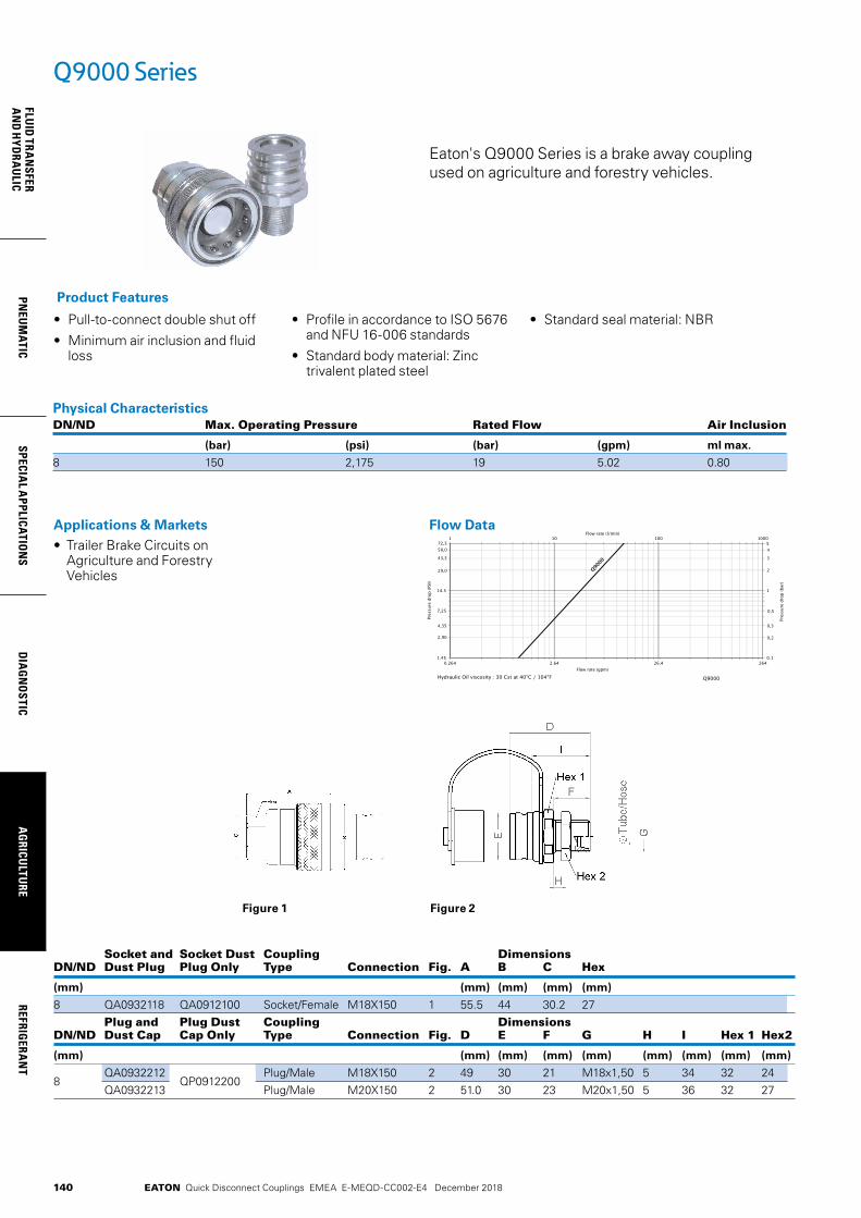
EATON Quick Disconnect Couplings EMEA E-MEQD-CC002-E4 December 2018140
FLUID
TRAN
SFERA
ND
HYD
RAU
LICPN
EUM
ATICSPECIA
L APPLICATIO
NS
DIA
GN
OSTIC
AG
RICULTU
REREFRIG
ERAN
T
Q9000 Series
Eaton's Q9000 Series is a brake away coupling used on agriculture and forestry vehicles.
• Pull-to-connect double shut off
• Minimum air inclusion and fluid loss
• Profile in accordance to ISO 5676 and NFU 16-006 standards
• Standard body material: Zinc trivalent plated steel
• Standard seal material: NBR
Product Features
Physical CharacteristicsDN/ND Max. Operating Pressure Rated Flow Air Inclusion
(bar) (psi) (bar) (gpm) ml max.
8 150 2,175 19 5.02 0.80
Applications & Markets• Trailer Brake Circuits on
Agriculture and Forestry Vehicles
Flow Data
Figure 1 Figure 2
Socket and Socket Dust Coupling Dimensions DN/ND Dust Plug Plug Only Type Connection Fig. A B C Hex
(mm) (mm) (mm) (mm) (mm)
8 QA0932118 QA0912100 Socket/Female M18X150 1 55.5 44 30.2 27 Plug and Plug Dust Coupling Dimensions DN/ND Dust Cap Cap Only Type Connection Fig. D E F G H I Hex 1 Hex2
(mm) (mm) (mm) (mm) (mm) (mm) (mm) (mm) (mm)
8 QA0932212
QP0912200 Plug/Male M18X150 2 49 30 21 M18x1,50 5 34 32 24
QA0932213 Plug/Male M20X150 2 51.0 30 23 M20x1,50 5 36 32 27

EATON Quick Disconnect Couplings EMEA E-MEQD-CC002-E4 December 2018
PNEU
MAT
ICSP
ECIA
L A
PPLI
CATI
ON
SD
IAG
NO
STIC
AG
RICU
LTU
RERE
FRIG
ERA
NT
FLU
ID T
RAN
SFER
AN
D H
YDRA
ULI
C
141
5400 Series Low Air Inclusion Refrigerant
4624.6246.2462.01.45
14.5
0.1
1
0001001011
Flow rate (gpm)
Pres
sure
dro
p (P
SI)
Pres
sure
dro
p (b
ar)
Flow rate (l/min)
Air flow rate at 100 PSI (6,89 bar) Inlet Pressure
29,0
2,90
4,35
7,25
2
0,2
0,3
0,5
Eaton’s 5400 Series low air inclusion product line is designed for air conditioning, refrigerant, gaseous and fluid transfer applications.
Product Features• Brazed or threaded end
connections for versatility of installation on tubing or hose
• Tubular valve construction for low fluid loss and air inclusion
• Thread together design allows connection and disconnection against pressure
• Lock washer and jam nut standard for optional bulkhead mounting
• Standard seal material: Neoprene
• Guardian Seal™ plating for excellent corrosion resistance
Physical Characteristics Max. Operating Pressure Vacuum Coupling Max. Operating Pressure Min. Burst Pressure Disconnected Connected Rated Air Fluid Size Connected Connected Male Half Female Half Only Flow Inclusion Loss
(in) (bar) (psi) (bar) (psi) (bar) (psi) (bar) (psi) (in./Hg) (lpm) (gpm) cc. max. cc.max.
1/4 207 3,000 621 9,000 172 2,500 52 750 28 8 2 .10 .051/2 121 1,750 359 5,200 121 1,750 52 750 28 53 14 .10 .10¾ 48 700 145 2,100 48 700 45 650 28 132 35 .30 .101 48 700 145 2,100 48 700 21 300 28 284 75 .50 .20
Applications & Markets• Mobile Air Conditioning
and Refrigerant
Flow Data

EATON Quick Disconnect Couplings EMEA E-MEQD-CC002-E4 December 2018
FLUID
TRAN
SFERA
ND
HYD
RAU
LICPN
EUM
ATICSPECIA
L APPLICATIO
NS
DIA
GN
OSTIC
AG
RICULTU
REREFRIG
ERAN
T
142
Figure 2 Figure 3Figure 1
Figure 4 Figure 6 Figure 7Figure 5
Dimensions – No AdapterPart Number Coupling Body Dimensions Neoprene Type Size Type Fig. A B Hex 1 Hex 2 Hex 3
mm (in) mm (in) mm (in) mm (in) mm (in)
5400-S2-4 Male 1/4 No Adapter 1 27.4 (1.08) 21.1 (.83) 19 (.75) - - - -5400-S5-4 Female 1/4 No Adapter 2 28.7 (1.13) 21.1 (.83) 16.0 (.63) 19 (.75) - -5400-S2-8 Male 1/2 No Adapter 1 34.8 (1.37) 32.0 (1.26) 29.0 (1.14) - - - -5400-S5-8 Female 1/2 No Adapter 2 40.6 (1.60) 33.0 (1.30) 26.0 (1.02) 30.0 (1.18) - -5400-S2-12 Male ¾ No Adapter 1 44.2 (1.74) 46.4 (1.83) 41.0 (1.61) - - - -5400-S5-12 Female ¾ No Adapter 2 55.1 (2.17) 45.0 (1.77) 35.0 (1.38) 41.0 (1.61) - -5400-S2-16 Male 1 No Adapter 1 46.5 (1.83) 53.0 (2.10) 48.0 (1.89) - - - -5400-S5-16 Female 1 No Adapter 2 61.1 (2.41) 56.0 (2.20) 45.0 (1.77) 50.0 (1.97) - -
Dimensions – SAE 37° (JIC) (Dimensional reference only)Part Number Coupling Body Port Dimensions Buna-N Type Size Size Thread Type Fig. A B Hex 1 Hex 2 Hex 3
*Couplings must be ordered by components as shown on page 147. mm (in) mm (in) mm (in) mm (in) mm (in)
5410-S17-4-4* Male 1/4 7/16 7/16-20 SAE 37° (JIC) 3 47.8 (1.88) 21.1 (.83) 19 (.75) - - 16.0 (.63)
5410-S14-4-4* Female 1/4 7/16 7/16-20 SAE 37° (JIC) 4 49.0 (1.93) 21.1 (.83) 16.0 (.63) 19 (.75) 15.7 (.62)
5410-4-4* Complete 1/4 7/16 7/16-20 SAE 37° (JIC) 5 89.9 (3.54) - - - - - - - -
5410-S17-6-4* Male 1/4 9/16 9/16-18 SAE 37° (JIC) 3 48.0 (1.89) 21.1 (.83) 19 (.75) - - 16.0 (.63)
5410-S14-6-4* Female 1/4 9/16 9/16-18 SAE 37° (JIC) 4 49.3 (1.94) 21.1 (.83) 16.0 (.63) 19 (.75) 15.7 (.62)
5410-6-4* Complete 1/4 9/16 9/16-18 SAE 37° (JIC) 5 90.4 (3.56) - - - - - - - -
5410-S17-6-8* Male 1/4 9/16 9/16-18 SAE 37° (JIC) 3 55.4 (2.18) 31.8 (1.25) 29 (1.14) - - 25.4 (1.00)
5410-S14-6-8* Female 1/2 9/16 9/16-18 SAE 37° (JIC) 4 61.7 (2.43) 33.3 (1.31) 26 (1.02) 30 (1.18) 25.4 (1.00)
5410-6-8* Complete 1/2 9/16 9/16-18 SAE 37° (JIC) 5 107.4 (4.23) - - - - - - - -
5410-S17-8-8* Male 1/2 ¾ ¾-16 SAE 37° (JIC) 3 57.9 (2.28) 31.8 (1.25) 29 (1.14) - - 25.4 (1.00)
5410-S14-8-8* Female 1/2 ¾ ¾-16 SAE 37° (JIC) 4 64.3 (2.53) 33.3 (1.31) 26 (1.02) 30 (1.18) 25.4 (1.00)
5410-8-8* Complete 1/2 ¾ ¾-16 SAE 37° (JIC) 5 112.8 (4.44) - - - - - - - -
5410-S17-10-12* Male ¾ 7/8 7/8-14 SAE 37° (JIC) 3 69.9 (2.75) 46.5 (1.83) 41 (1.62) - - 35.1 (1.38)
5410-S14-10-12* Female ¾ 7/8 7/8-14 SAE 37° (JIC) 4 80.3 (3.16) 45.7 (1.80) 35 (1.38) 41 (1.62) 35.1 (1.38)
5410-10-12* Complete ¾ 7/8 7/8-14 SAE 37° (JIC) 5 135.4 (5.33) - - - - - - - -
5410-S17-12-12* Male ¾ 1 1/16 1 1/16-12 SAE 37° (JIC) 3 72.6 (2.86) 46.5 (1.83) 41 (1.62) - - 35.1 (1.38)
5410-S14-12-12* Female ¾ 1 1/16 1 1/16-12 SAE 37° (JIC) 4 83.1 (3.27) 45.7 (1.80) 35 (1.38) 41 (1.62) 35.1 (1.38)
5410-12-12* Complete ¾ 1 1/16 1 1/16-12 SAE 37° (JIC) 5 140.7 (5.54) - - - - - - - -
5410-S17-16-16* Male 1 1 5/16 1 5/16-12 SAE 37° (JIC) 3 75.9 (2.99) 53.3 (2.10) 48 (1.89) - - 44.5 (1.75)
5410-S14-16-16* Female 1 1 5/16 1 5/16-12 SAE 37° (JIC) 4 89.7 (3.53) 56.9 (2.24) 45 (1.77) 50 (1.97) 44.5 (1.75)
5410-16-16* Complete 1 1 5/16 1 5/16-12 SAE 37° (JIC) 5 149.6 (5.89) - - - - - - - -
Above items must be ordered at the component level - see page 148.
5400 Series Low Air Inclusion Refrigerant
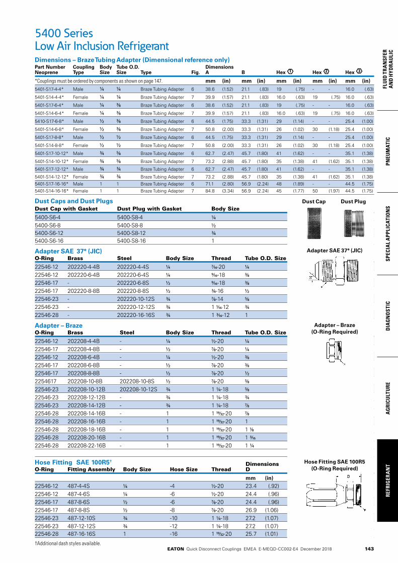
EATON Quick Disconnect Couplings EMEA E-MEQD-CC002-E4 December 2018
PNEU
MAT
ICSP
ECIA
L A
PPLI
CATI
ON
SD
IAG
NO
STIC
AG
RICU
LTU
RERE
FRIG
ERA
NT
FLU
ID T
RAN
SFER
AN
D H
YDRA
ULI
C
143
5400 Series Low Air Inclusion RefrigerantDimensions – Braze Tubing Adapter (Dimensional reference only)Part Number Coupling Body Tube O.D. Dimensions Neoprene Type Size Size Type Fig. A B Hex 1 Hex 2 Hex 3
*Couplings must be ordered by components as shown on page 147. mm (in) mm (in) mm (in) mm (in) mm (in)
5401-S17-4-4* Male 1/4 1/4 Braze Tubing Adapter 6 38.6 (1.52) 21.1 (.83) 19 (.75) - - 16.0 (.63)
5401-S14-4-4* Female 1/4 1/4 Braze Tubing Adapter 7 39.9 (1.57) 21.1 (.83) 16.0 (.63) 19 (.75) 16.0 (.63)
5401-S17-6-4* Male 1/4 3/8 Braze Tubing Adapter 6 38.6 (1.52) 21.1 (.83) 19 (.75) - - 16.0 (.63)
5401-S14-6-4* Female 1/4 3/8 Braze Tubing Adapter 7 39.9 (1.57) 21.1 (.83) 16.0 (.63) 19 (.75) 16.0 (.63)
5410-S17-6-8* Male 1/2 3/8 Braze Tubing Adapter 6 44.5 (1.75) 33.3 (1.31) 29 (1.14) - - 25.4 (1.00)
5401-S14-6-8* Female 1/2 3/8 Braze Tubing Adapter 7 50.8 (2.00) 33.3 (1.31) 26 (1.02) 30 (1.18) 25.4 (1.00)
5401-S17-8-8* Male 1/2 1/2 Braze Tubing Adapter 6 44.5 (1.75) 33.3 (1.31) 29 (1.14) - - 25.4 (1.00)
5401-S14-8-8* Female 1/2 1/2 Braze Tubing Adapter 7 50.8 (2.00) 33.3 (1.31) 26 (1.02) 30 (1.18) 25.4 (1.00)
5401-S17-10-12* Male ¾ 5/8 Braze Tubing Adapter 6 62.7 (2.47) 45.7 (1.80) 41 (1.62) - - 35.1 (1.38)
5401-S14-10-12* Female ¾ 5/8 Braze Tubing Adapter 7 73.2 (2.88) 45.7 (1.80) 35 (1.38) 41 (1.62) 35.1 (1.38)
5401-S17-12-12* Male ¾ ¾ Braze Tubing Adapter 6 62.7 (2.47) 45.7 (1.80) 41 (1.62) - - 35.1 (1.38)
5401-S14-12-12* Female ¾ ¾ Braze Tubing Adapter 7 73.2 (2.88) 45.7 (1.80) 35 (1.38) 41 (1.62) 35.1 (1.38)5401-S17-16-16* Male 1 1 Braze Tubing Adapter 6 71.1 (2.80) 56.9 (2.24) 48 (1.89) - - 44.5 (1.75)5401-S14-16-16* Female 1 1 Braze Tubing Adapter 7 84.8 (3.34) 56.9 (2.24) 45 (1.77) 50 (1.97) 44.5 (1.75)
Dust Caps and Dust PlugsDust Cap with Gasket Dust Plug with Gasket Body Size
5400-S6-4 5400-S8-4 1/45400-S6-8 5400-S8-8 1/25400-S6-12 5400-S8-12 ¾5400-S6-16 5400-S8-16 1
Adapter SAE 37° (JIC)O-Ring Brass Steel Body Size Thread Tube O.D. Size
22546-12 202220-4-4B 202220-4-4S 1/4 7/16-20 1/422546-12 202220-6-4B 202220-6-4S 1/4 9/16-18 3/822546-17 - 202220-6-8S 1/2 9/16-18 3/822546-17 202220-8-8B 202220-8-8S 1/2 ¾-16 1/222546-23 - 202220-10-12S ¾ 7/8-14 5/822546-23 - 202220-12-12S ¾ 1 1/16-12 ¾22546-28 - 202220-16-16S ¾ 1 3/16-12 1
Adapter – BrazeO-Ring Brass Steel Body Size Thread Tube O.D. Size
22546-12 202208-4-4B - 1/4 1/2-20 1/422546-17 202208-4-8B - 1/2 7/8-20 1/422546-12 202208-6-4B - 1/4 1/2-20 3/822546-17 202208-6-8B - 1/2 7/8-20 3/822546-17 202208-8-8B - 1/2 7/8-20 1/22254617 202208-10-8B 202208-10-8S 1/2 7/8-20 5/822546-23 202208-10-12B 202208-10-12S ¾ 1 1/4-18 5/822546-23 202208-12-12B - ¾ 1 1/4-18 ¾22546-23 202208-14-12B - ¾ 1 1/4-18 7/822546-28 202208-14-16B - 1 1 19/32-20 7/822546-28 202208-16-16B - 1 1 19/32-20 122546-28 202208-18-16B - 1 1 19/32-20 1 1/822546-28 202208-20-16B - 1 1 19/32-20 1 3/1622546-28 202208-22-16B - 1 1 19/32-20 1 1/4
Hose Fitting SAE 100R5† Dimensions
O-Ring Fitting Assembly Body Size Hose Size Thread D
mm (in)
22546-12 487-4-4S 1/4 -4 1/2-20 23.4 (.92)22546-12 487-4-6S 1/4 -6 1/2-20 24.4 (.96)22546-17 487-8-6S 1/2 -6 7/8-20 24.4 (.96)22546-17 487-8-8S 1/2 -8 7/8-20 26.9 (1.06)22546-23 487-12-10S ¾ -10 1 1/4-18 27.2 (1.07)22546-23 487-12-12S ¾ -12 1 1/4-18 27.2 (1.07)22546-28 487-16-16S 1 -16 1 19/32-20 25.7 (1.01)
†Additional dash styles available.
Adapter SAE 37° (JIC)
Adapter – Braze(O-Ring Required)
Hose Fitting SAE 100R5(O-Ring Required)
Dust Cap Dust Plug

EATON Quick Disconnect Couplings EMEA E-MEQD-CC002-E4 December 2018
FLUID
TRAN
SFERA
ND
HYD
RAU
LICPN
EUM
ATICSPECIA
L APPLICATIO
NS
DIA
GN
OSTIC
AG
RICULTU
REREFRIG
ERAN
T
144
5400 Series Low Air Inclusion Refrigerant
For assemblies, order by components as shown by base number and dash (-) size below. Example, if a 5401-S14-10-12 is required, order as components, (1) 5400-S5-12, (1) 202208-10-12B Adapter and (1) 22546-23 O-Ring.
Assembly 5400-S2 5400-S5 202208-Brass 202220-Steel Part Male Female Braze-On 37˚ SAE 22546 Number Half Quantity Half Quantity Adapter Quantity Adapter Quantity O-Ring Quantity
5401-S14-10-12 -12 1 -10 -12B 1 -23 15401-S14-10-8 -8 1 -10 -8B -17 15401-S14-12-12 -12 1 -12 -12B 1 -23 15401-S14-16-16 -16 1 -16 -16B 1 -28 15401-S14-4-4 -4 1 -4 -4B 1 -12 15401-S14-6-4 -4 1 -6 -4B 1 -12 15401-S14-6-8 -8 1 -6 -8B 1 -17 15401-S14-8-8 -8 1 -8 -8B 1 -17 15401-S17-10-12 -12 1 -10 -12B 1 -23 15401-S17-10-8 -8 1 -10 -8B 1 -17 15401-S17-12-12 -12 1 -12 -12 1 -23 15401-S17-14-16 -16 1 -16 -16 1 -28 15401-S17-4-4 -4 1 -4 -4B 1 -17 15401-S17-6-4 -4 1 -6 -4B 1 -12 15401-S17-6-8 -8 1 -6 -8B 1 -17 15401-S17-8-8 -8 1 -8 -8B 1 -17 15410-12-12 -12 1 -12 1 -12 -12S 2 -23 25410-16-16 -16 1 -16 1 -16 -16S 2 -28 25410-4-4 -4 1 -4 1 -4 -4S 2 -12 25410-6-8 -8 1 -8 1 -6 -8S 2 -17 25410-8-8 -8 1 -8 1 -8 -8S 2 -17 25410-S14-10-12 -12 1 -10 -12S 1 -23 15410-S14-12-12 -12 1 -12 -12S 1 -23 15410-S14-16-16 -16 1 -16 -16S 1 -28 15410-S14-4-4 -4 1 -4 -4S 1 -12 15410-S14-6-4 -4 1 -6 -4S 1 -12 15410-S14-6-8 -8 1 -6 -8S 1 -17 15410-S14-8-8 -8 1 -8 -8S 1 -17 15410-S17-10-12 -12 1 -10 -12S 1 -23 15410-S17-12-12 -12 1 -12 -12S 1 -23 15410-S17-16-16 -16 1 -16 -16S 1 -28 15410-S17-4-4 -4 1 -4 -4S 1 -12 15410-S17-6-4 -4 1 -6 -4S 1 -12 15410-S17-6-8 -8 1 -6 -8S 1 -17 15410-S17-8-8 -8 1 -8 -8S 1 -17 1
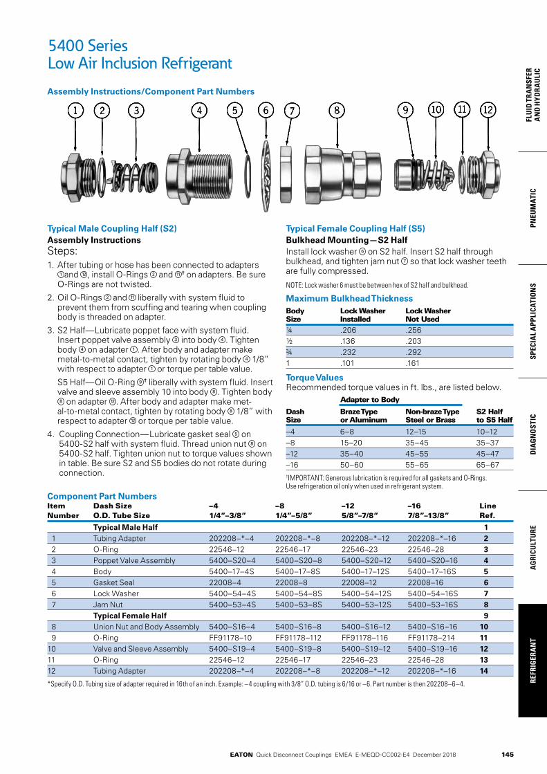
EATON Quick Disconnect Couplings EMEA E-MEQD-CC002-E4 December 2018
PNEU
MAT
ICSP
ECIA
L A
PPLI
CATI
ON
SD
IAG
NO
STIC
AG
RICU
LTU
RERE
FRIG
ERA
NT
FLU
ID T
RAN
SFER
AN
D H
YDRA
ULI
C
145
5400 Series Low Air Inclusion Refrigerant
Component Part NumbersItem Dash Size –4 –8 –12 –16 Line Number O.D. Tube Size 1/4”–3/8” 1/4”–5/8” 5/8”–7/8” 7/8”–13/8” Ref.
Typical Male Half 1 1 Tubing Adapter 202208–*–4 202208–*–8 202208–*–12 202208–*–16 2 2 O-Ring 22546–12 22546–17 22546–23 22546–28 3 3 Poppet Valve Assembly 5400–S20–4 5400–S20–8 5400–S20–12 5400–S20–16 4 4 Body 5400–17–4S 5400–17–8S 5400–17–12S 5400–17–16S 5 5 Gasket Seal 22008–4 22008–8 22008–12 22008–16 6 6 Lock Washer 5400–54–4S 5400–54–8S 5400–54–12S 5400–54–16S 7 7 Jam Nut 5400–53–4S 5400–53–8S 5400–53–12S 5400–53–16S 8 Typical Female Half 9 8 Union Nut and Body Assembly 5400–S16–4 5400–S16–8 5400–S16–12 5400–S16–16 10 9 O-Ring FF91178–10 FF91178–112 FF91178–116 FF91178–214 1110 Valve and Sleeve Assembly 5400–S19–4 5400–S19–8 5400–S19–12 5400–S19–16 1211 O-Ring 22546–12 22546–17 22546–23 22546–28 1312 Tubing Adapter 202208–*–4 202208–*–8 202208–*–12 202208–*–16 14
*Specify O.D. Tubing size of adapter required in 16th of an inch. Example: –4 coupling with 3/8” O.D. tubing is 6/16 or –6. Part number is then 202208–6–4.
Typical Male Coupling Half (S2)Assembly InstructionsSteps:1. After tubing or hose has been connected to adapters
1 and 12 , install O-Rings 2 and 11 † on adapters. Be sure O-Rings are not twisted.
2. Oil O-Rings 2 and 11 liberally with system fluid to prevent them from scuffing and tearing when coupling body is threaded on adapter.
3. S2 Half—Lubricate poppet face with system fluid. Insert poppet valve assembly 3 into body 4 . Tighten body 4 on adapter 1 . After body and adapter make metal-to-metal contact, tighten by rotating body 4 1/8” with respect to adapter 1 or torque per table value.
S5 Half—Oil O-Ring 9 † liberally with system fluid. In sert valve and sleeve assembly 10 into body 8 . Tighten body 8 on adapter 12 . After body and adapter make met-al-to-metal contact, tighten by rotating body 8 1/8” with respect to adapter 12 or torque per table value.
4. Coupling Connection—Lubricate gasket seal 5 on 5400-S2 half with system fluid. Thread union nut 8 on 5400-S2 half. Tighten union nut to torque values shown in table. Be sure S2 and S5 bodies do not rotate during connection.
Assembly Instructions/Component Part Numbers
Typical Female Coupling Half (S5)Bulkhead Mounting—S2 HalfInstall lock washer 6 on S2 half. Insert S2 half through bulkhead, and tighten jam nut 7 so that lock washer teeth are fully compressed.
NOTE: Lock washer 6 must be between hex of S2 half and bulkhead.
Maximum Bulkhead Thickness Body Lock Washer Lock Washer Size Installed Not Used¼ .206 .256½ .136 .203¾ .232 .2921 .101 .161
Torque ValuesRecommended torque values in ft. lbs., are listed below. Adapter to Body
Dash Braze Type Non-braze Type S2 Half Size or Aluminum Steel or Brass to S5 Half
–4 6–8 12–15 10–12–8 15–20 35–45 35–37–12 35–40 45–55 45–47–16 50–60 55–65 65–67†IMPORTANT: Generous lubrication is required for all gaskets and O-Rings. Use refrigeration oil only when used in refrigerant system.
146 EATON Quick Disconnect Couplings EMEA E-MEQD-CC002-E4 December 2018
Part Number Index
Part Number Page Number
10 75, 85, 90
11 75, 85, 90
13 85
14 85
16 86
17 86
900 85
1100 85
1200 85
1300 85
1800 86
2254617 147
1000E 85
10C 85
10FFP10L 37
10FFP12L 37
10FFP15L 37
10FFP15LBH 37
10FFP16FMET 36
10FFP16S 37
10FFP37 36
10FFP37BS 36
10FFP37FG 36
10FFP50 36
10FFP50BS 36
10FFP50FG 36
10FFP56ORM 37
10FFP56UN 36
10FFP75ORM 37
10FFP75UN 36
10FFP87UN 36
10FFP8L 37
10FFPCUP37 41
10FFPCUP37BS 41
10FFPCUP50 41
10FFPCUP50BS 41
10FFS10L 35
10FFS12L 35
10FFS15L 35
10FFS15LBH 35
10FFS16FMET 34
10FFS16S 35
10FFS37 34
10FFS37BS 34
10FFS37FG 34
10FFS50 34
10FFS50BS 34
10FFS50FG 34
Part Number Page Number
10FFS56ORM 35
10FFS56UN 34
10FFS75ORM 35
10FFS75UN 34
10FFS87UN 34
10FFS8L 35
10G 87
10H41 9
10H41BS 9
10K41 10
10K41BS 10
10NK 85
10S41 118
10S41BS 118
10T40 117
10T41 118
11B 85
11G 85
11NK 85
12E 85
12FFP106UN 36
12FFP15LBH 37
12FFP16S 37
12FFP18LBH 37
12FFP50 36
12FFP50BS 36
12FFP50FG 36
12FFP75 36
12FFP75BS 36
12FFP75FG 36
12FFP75UN 36
12FFP87UN 36
12FFPCUP50 41
12FFPCUP50BS 41
12FFPCUP56UN 41
12FFPCUP75UN 41
12FFS106UN 34
12FFS15LBH 35
12FFS16S 35
12FFS18LBH 35
12FFS50 34
12FFS50BS 34
12FFS50FG 34
12FFS75 34
12FFS75BS 34
12FFS75FG 34
12FFS75UN 34
12FFS87UN 34

147EATON Quick Disconnect Couplings EMEA E-MEQD-CC002-E4 December 2018
Part Number Index
Part Number Page Number
12G 87
12H41 9
12H41BS 9
12H46 9
12H46BS 9
12IAP10L 23
12IAP10LBH 23
12IAP12L 23
12IAP12LBH 23
12IAP12S 23
12IAP15L 23
12IAP15LBH 23
12IAP16FMET 23
12IAP16S 23
12IAP37 23
12IAP37BS 23
12IAP50 23
12IAP50BS 23
12IAP56ORM 23
12IAP56UN 23
12IAP75ORM 23
12IAP75UN 23
12IAP87UN 23
12IAP8L 23
12IAS10L 22
12IAS10LBH 22
12IAS12L 22
12IAS12LBH 22
12IAS12S 22
12IAS15L 22
12IAS15LBH 22
12IAS16FMET 22
12IAS16S 22
12IAS37 22
12IAS37BS 22
12IAS50 22
12IAS50BS 22
12IAS56ORM 22
12IAS56UN 22
12IAS75ORM 22
12IAS75UN 22
12IAS87UN 22
12IAS8L 22
12K41 10
12K41BS 10
12K46 10
12K46BS 10
12S46 118
Part Number Page Number
12S46BS 118
12T45 117
12T46 118
14G 85
150-22-12 51
150-22-16 51
150-22-20 51
150-22-5 51
150-22-8 51
15E 85
1600E 86
1600P 86
16FFP106UN 36
16FFP15LBH 37
16FFP16S 37
16FFP18LBH 37
16FFP50 36
16FFP50BS 36
16FFP75 36
16FFP75BS 36
16FFP75FG 36
16FFP75UN 36
16FFP87UN 36
16FFS106UN 34
16FFS15LBH 35
16FFS16S 35
16FFS18LBH 35
16FFS50 34
16FFS50BS 34
16FFS75 34
16FFS75BS 34
16FFS75FG 34
16FFS75UN 34
16FFS87UN 34
16G 86
16NK 86
16P 86
16S51 118
16S51BS 118
16T50 117
16T51 118
1700E 86
1700P 86
17G 86
17NK 86
17P 86
18E 86
19FFP100 36
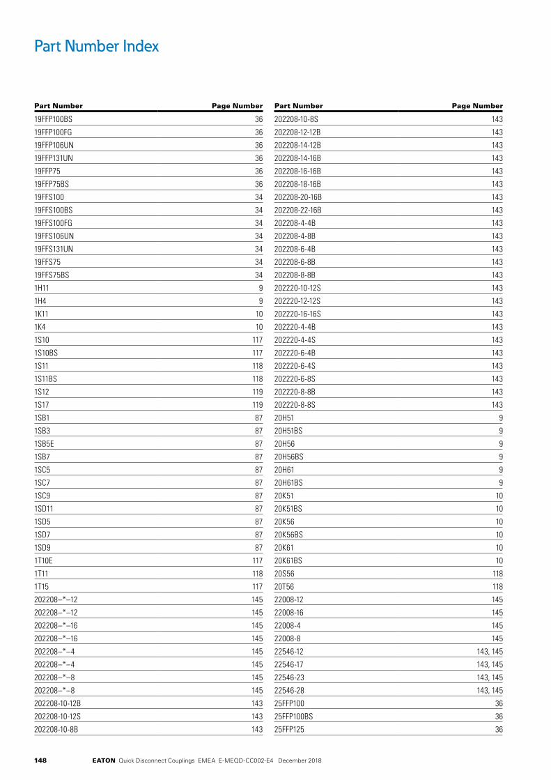
148 EATON Quick Disconnect Couplings EMEA E-MEQD-CC002-E4 December 2018
Part Number Index
Part Number Page Number
19FFP100BS 36
19FFP100FG 36
19FFP106UN 36
19FFP131UN 36
19FFP75 36
19FFP75BS 36
19FFS100 34
19FFS100BS 34
19FFS100FG 34
19FFS106UN 34
19FFS131UN 34
19FFS75 34
19FFS75BS 34
1H11 9
1H4 9
1K11 10
1K4 10
1S10 117
1S10BS 117
1S11 118
1S11BS 118
1S12 119
1S17 119
1SB1 87
1SB3 87
1SB5E 87
1SB7 87
1SC5 87
1SC7 87
1SC9 87
1SD11 87
1SD5 87
1SD7 87
1SD9 87
1T10E 117
1T11 118
1T15 117
202208–*–12 145
202208–*–12 145
202208–*–16 145
202208–*–16 145
202208–*–4 145
202208–*–4 145
202208–*–8 145
202208–*–8 145
202208-10-12B 143
202208-10-12S 143
202208-10-8B 143
Part Number Page Number
202208-10-8S 143
202208-12-12B 143
202208-14-12B 143
202208-14-16B 143
202208-16-16B 143
202208-18-16B 143
202208-20-16B 143
202208-22-16B 143
202208-4-4B 143
202208-4-8B 143
202208-6-4B 143
202208-6-8B 143
202208-8-8B 143
202220-10-12S 143
202220-12-12S 143
202220-16-16S 143
202220-4-4B 143
202220-4-4S 143
202220-6-4B 143
202220-6-4S 143
202220-6-8S 143
202220-8-8B 143
202220-8-8S 143
20H51 9
20H51BS 9
20H56 9
20H56BS 9
20H61 9
20H61BS 9
20K51 10
20K51BS 10
20K56 10
20K56BS 10
20K61 10
20K61BS 10
20S56 118
20T56 118
22008-12 145
22008-16 145
22008-4 145
22008-8 145
22546-12 143, 145
22546-17 143, 145
22546-23 143, 145
22546-28 143, 145
25FFP100 36
25FFP100BS 36
25FFP125 36

149EATON Quick Disconnect Couplings EMEA E-MEQD-CC002-E4 December 2018
Part Number Index
Part Number Page Number
25FFP125BS 36
25FFP125FG 36
25FFP131UN 36
25FFP162UN 36
32FFP125 36
32FFP162UN 36
40FFP150 36
40FFP150BS 36
40FFP187UN 36
50FFP200 36
50FFP200BS 36
50FFP250UN 36
32FFS125 34
25FFS100 34
25FFS100BS 34
25FFS125 34
25FFS125BS 34
25FFS125FG 34
25FFS131UN 34
25FFS162UN 34
32FFS125BS 34
32FFS162UN 34
40FFS150 39
40FFS150BS 39
40FFS187UN 34
50FFS200 39
50FFS200BS 39
50FFS250UN 34
2DBPG143 45
2DBPG242 45
2DBPG292 45
2DBPG503 45
2DBSG143 45
2DBSG242 45
2DBSG292 45
2DBSG503 45
2H16 9
2H16BS 9
2H6 9
2HIG10 114
2HIG11 114
2HIG15 114
2HIG16 114
2HIG20 114
2HIG720 114
2HIGLLRA720 114
2HIL10 115
2HIL11 115
Part Number Page Number
2HIL15 115
2HIL16 115
2HIL20 115
2HIL720 115
2HILLLRA720 115
2K16 10
2K16BS 10
2K6 10
2KIGF 114
2KIGF15 114
2KIGF16 114
2KIGF20 114
2KIGF720 114
2KILF 115
2KILF15 115
2KILF16 115
2KILF20 115
2KILF720 115
2S15 117
2S16 118
2S16BS 118
2S17 119
2T15 117
2T16 118
2UHP25 36
2UHP25BS 36
2UHS25 36
2UHS25BS 36
3H21 9
3H21BS 9
3H8 9
3K21 10
3K21BS 10
3K8 10
3PB1 87
3PB11 87
3PB3 87
3PB5 87
3PB7 87
3PB9 87
3PC5 87
3PC7 87
3PC9 87
3PD11 87
3PD5 87
3PD7 87
3PD9 87
3S20 117

150 EATON Quick Disconnect Couplings EMEA E-MEQD-CC002-E4 December 2018
Part Number Index
Part Number Page Number
3S20BS 117
3S21 118
3S21BS 118
3S22 119
3T20 117
3T21 118
487-12-10S 143
487-12-12S 143
487-16-16S 143
487-4-4S 143
487-4-6S 143
487-8-6S 143
487-8-8S 143
4DBPG143 45
4DBPG242 45
4DBPG292 45
4DBPG503 45
4DBSG143 45
4DBSG242 45
4DBSG292 45
4DBSG503 45
4HP10 9
4HP26 9
4HP26BS 9
4KP10 10
4KP26 10
4KP26BS 10
4S25 117
4S25BS 117
4S26 118
4S26BS 118
4S27 119
4T25 117
4T26 118
5100-10B 51
5100-12B 51
5100-16B 51
5100-20B 51
5100-22-245 51
5100-24B 51
5100-4B 51
5100-6B 51
5100-8B 51
5100-S2-10B 49
5100-S2-12B 49
5100-S2-16B 49
5100-S2-20B 49
5100-S2-24B 49
Part Number Page Number
5100-S2-4B 49
5100-S2-6B 49
5100-S2-8B 49
5100-S4-10B 50
5100-S4-12B 50
5100-S4-16B 50
5100-S4-20B 50
5100-S4-24B 50
5100-S4-4B 50
5100-S4-6B 50
5100-S4-8B 50
5100-S5-10B 50
5100-S5-12B 50
5100-S5-16B 50
5100-S5-20B 50
5100-S5-24B 50
5100-S5-4B 50
5100-S5-6B 50
5100-S5-8B 50
5100-S7-12 51
5100-S7-16 51
5100-S7-20 51
5100-S7-24 51
5100-S7-5 51
5100-S7-8 51
5100-S9-12 51
5100-S9-16 51
5100-S9-20 51
5100-S9-24 51
5100-S9-5 51
5100-S9-8 51
5101-10B 50
5101-12B 50
5101-16B 50
5101-20B 50
5101-24B 50
5101-4B 50
5101-6B 50
5101-8B 50
5110-10B 50
5110-12B 50
5110-20B 50
5110-4B 50
5110-6B 50
5110-8B 50
5110-S5-10B 49
5110-S5-12B 49
5110-S5-16B 49
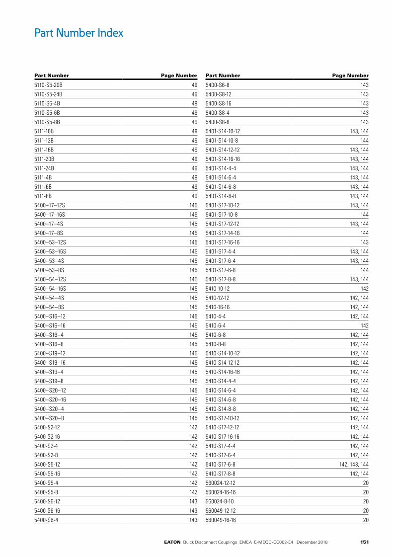
151EATON Quick Disconnect Couplings EMEA E-MEQD-CC002-E4 December 2018
Part Number Index
Part Number Page Number
5110-S5-20B 49
5110-S5-24B 49
5110-S5-4B 49
5110-S5-6B 49
5110-S5-8B 49
5111-10B 49
5111-12B 49
5111-16B 49
5111-20B 49
5111-24B 49
5111-4B 49
5111-6B 49
5111-8B 49
5400–17–12S 145
5400–17–16S 145
5400–17–4S 145
5400–17–8S 145
5400–53–12S 145
5400–53–16S 145
5400–53–4S 145
5400–53–8S 145
5400–54–12S 145
5400–54–16S 145
5400–54–4S 145
5400–54–8S 145
5400–S16–12 145
5400–S16–16 145
5400–S16–4 145
5400–S16–8 145
5400–S19–12 145
5400–S19–16 145
5400–S19–4 145
5400–S19–8 145
5400–S20–12 145
5400–S20–16 145
5400–S20–4 145
5400–S20–8 145
5400-S2-12 142
5400-S2-16 142
5400-S2-4 142
5400-S2-8 142
5400-S5-12 142
5400-S5-16 142
5400-S5-4 142
5400-S5-8 142
5400-S6-12 143
5400-S6-16 143
5400-S6-4 143
Part Number Page Number
5400-S6-8 143
5400-S8-12 143
5400-S8-16 143
5400-S8-4 143
5400-S8-8 143
5401-S14-10-12 143, 144
5401-S14-10-8 144
5401-S14-12-12 143, 144
5401-S14-16-16 143, 144
5401-S14-4-4 143, 144
5401-S14-6-4 143, 144
5401-S14-6-8 143, 144
5401-S14-8-8 143, 144
5401-S17-10-12 143, 144
5401-S17-10-8 144
5401-S17-12-12 143, 144
5401-S17-14-16 144
5401-S17-16-16 143
5401-S17-4-4 143, 144
5401-S17-6-4 143, 144
5401-S17-6-8 144
5401-S17-8-8 143, 144
5410-10-12 142
5410-12-12 142, 144
5410-16-16 142, 144
5410-4-4 142, 144
5410-6-4 142
5410-6-8 142, 144
5410-8-8 142, 144
5410-S14-10-12 142, 144
5410-S14-12-12 142, 144
5410-S14-16-16 142, 144
5410-S14-4-4 142, 144
5410-S14-6-4 142, 144
5410-S14-6-8 142, 144
5410-S14-8-8 142, 144
5410-S17-10-12 142, 144
5410-S17-12-12 142, 144
5410-S17-16-16 142, 144
5410-S17-4-4 142, 144
5410-S17-6-4 142, 144
5410-S17-6-8 142, 143, 144
5410-S17-8-8 142, 144
560024-12-12 20
560024-16-16 20
560024-8-10 20
560049-12-12 20
560049-16-16 20
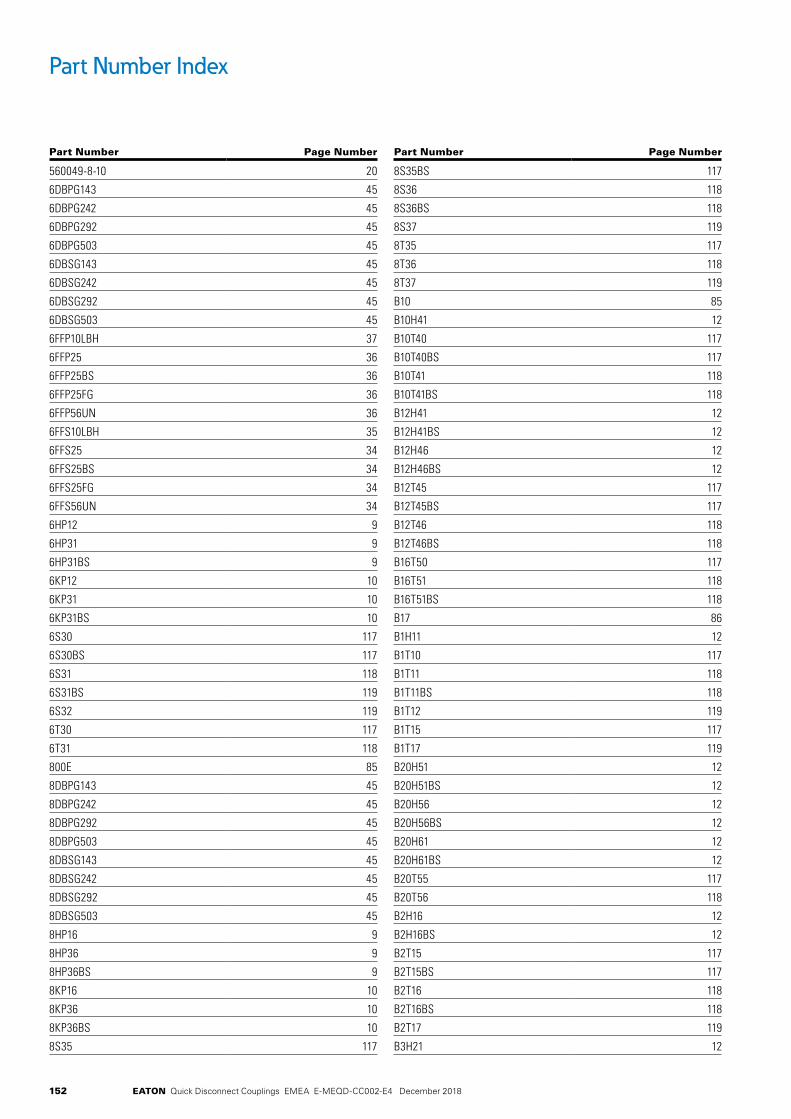
152 EATON Quick Disconnect Couplings EMEA E-MEQD-CC002-E4 December 2018
Part Number Index
Part Number Page Number
560049-8-10 20
6DBPG143 45
6DBPG242 45
6DBPG292 45
6DBPG503 45
6DBSG143 45
6DBSG242 45
6DBSG292 45
6DBSG503 45
6FFP10LBH 37
6FFP25 36
6FFP25BS 36
6FFP25FG 36
6FFP56UN 36
6FFS10LBH 35
6FFS25 34
6FFS25BS 34
6FFS25FG 34
6FFS56UN 34
6HP12 9
6HP31 9
6HP31BS 9
6KP12 10
6KP31 10
6KP31BS 10
6S30 117
6S30BS 117
6S31 118
6S31BS 119
6S32 119
6T30 117
6T31 118
800E 85
8DBPG143 45
8DBPG242 45
8DBPG292 45
8DBPG503 45
8DBSG143 45
8DBSG242 45
8DBSG292 45
8DBSG503 45
8HP16 9
8HP36 9
8HP36BS 9
8KP16 10
8KP36 10
8KP36BS 10
8S35 117
Part Number Page Number
8S35BS 117
8S36 118
8S36BS 118
8S37 119
8T35 117
8T36 118
8T37 119
B10 85
B10H41 12
B10T40 117
B10T40BS 117
B10T41 118
B10T41BS 118
B12H41 12
B12H41BS 12
B12H46 12
B12H46BS 12
B12T45 117
B12T45BS 117
B12T46 118
B12T46BS 118
B16T50 117
B16T51 118
B16T51BS 118
B17 86
B1H11 12
B1T10 117
B1T11 118
B1T11BS 118
B1T12 119
B1T15 117
B1T17 119
B20H51 12
B20H51BS 12
B20H56 12
B20H56BS 12
B20H61 12
B20H61BS 12
B20T55 117
B20T56 118
B2H16 12
B2H16BS 12
B2T15 117
B2T15BS 117
B2T16 118
B2T16BS 118
B2T17 119
B3H21 12

153EATON Quick Disconnect Couplings EMEA E-MEQD-CC002-E4 December 2018
Part Number Index
Part Number Page Number
B3H21BS 12
B3T20 117
B3T20BS 117
B3T21 118
B3T21BS 118
B3T22 119
B4HP26 12
B4HP26BS 12
B4T25 117
B4T25BS 117
B4T26 118
B4T26BS 118
B4T27 119
B6HP31 12
B6HP31BS 12
B6T30 117
B6T30BS 117
B6T31 118
B6T31BS 118
B6T32 119
B8HP36 12
B8HP36BS 12
B8T35 117
B8T35BS 117
B8T36 118
B8T36BS 118
B8T37 119
CR10FFPDG 37, 39, 41, 45, 47
CR10FFPLB 37, 39, 41, 45, 47
CR10FFPRD 37, 39, 41, 45, 47
CR10FFPYL 37, 39, 41, 45, 47
CR10FFSDG 37, 39, 41, 45, 47
CR10FFSLB 37, 39, 41, 45, 47
CR10FFSP93 37, 39, 41, 45, 47
CR10FFSRD 37, 39, 41, 45, 47
CR10FFSYL 37, 39, 41, 45, 47
CR12FFPDG 37, 39, 41, 45, 47
CR12FFPLB 37, 39, 41, 45, 47
CR12FFPRD 37, 39, 41, 45, 47
CR12FFPYL 37, 39, 41, 45, 47
CR12FFSDG 37, 39, 41, 45, 47
CR12FFSLB 37, 39, 41, 45, 47
CR12FFSP93 37, 39, 41, 45, 47
CR12FFSRD 37, 39, 41, 45, 47
CR12FFSYL 37, 39, 41, 45, 47
CR16FFPDG 37, 39, 41, 45, 47
CR16FFPLB 37, 39, 41, 45, 47
CR16FFPRD 37, 39, 41, 45, 47
Part Number Page Number
CR16FFPYL 37, 39, 41, 45, 47
CR16FFSDG 37, 39, 41, 45, 47
CR16FFSLB 37, 39, 41, 45, 47
CR16FFSP93 37, 39, 41, 45, 47
CR16FFSRD 37, 39, 41, 45, 47
CR16FFSYL 37, 39, 41, 45, 47
CR19FFPDG 37, 39, 41, 45, 47
CR19FFPLB 37, 39, 41, 45, 47
CR19FFPRD 37, 39, 41, 45, 47
CR19FFPYL 37, 39, 41, 45, 47
CR19FFSDG 37, 39, 41, 45, 47
CR19FFSLB 37, 39, 41, 45, 47
CR19FFSP93 37, 39, 41, 45, 47
CR19FFSRD 37, 39, 41, 45, 47
CR19FFSYL 37, 39, 41, 45, 47
CR4DBSP93 37, 39, 41, 45, 47
CRKIT10FF 37, 39, 41, 45, 47
CRKIT12FF 37, 39, 41, 45, 47
CRKIT16FF 37, 39, 41, 45, 47
CRKIT19FF 37, 39, 41, 45, 47
CRKIT4DB 37, 39, 41, 45, 47
EA0070278 106
EA0070289 106
EA0070290 106
EA0070401 106
EA0070411 106
EA0070412 106
EA0070413 106
EA0070467 106
EA0070478 106
EA0070489 106
EA0070490 106
EA0070601 106
EA0070611 106
EA0070612 106
EA0070613 106
EA0070616 106
EA0070678 106
EA0070689 106
EA0070690 106
EA0070811 106
EA0070812 106
EA0070813 106
EA0070816 106
EA0070819 106
EA0070889 106
EA0071016 106
EA0071019 106
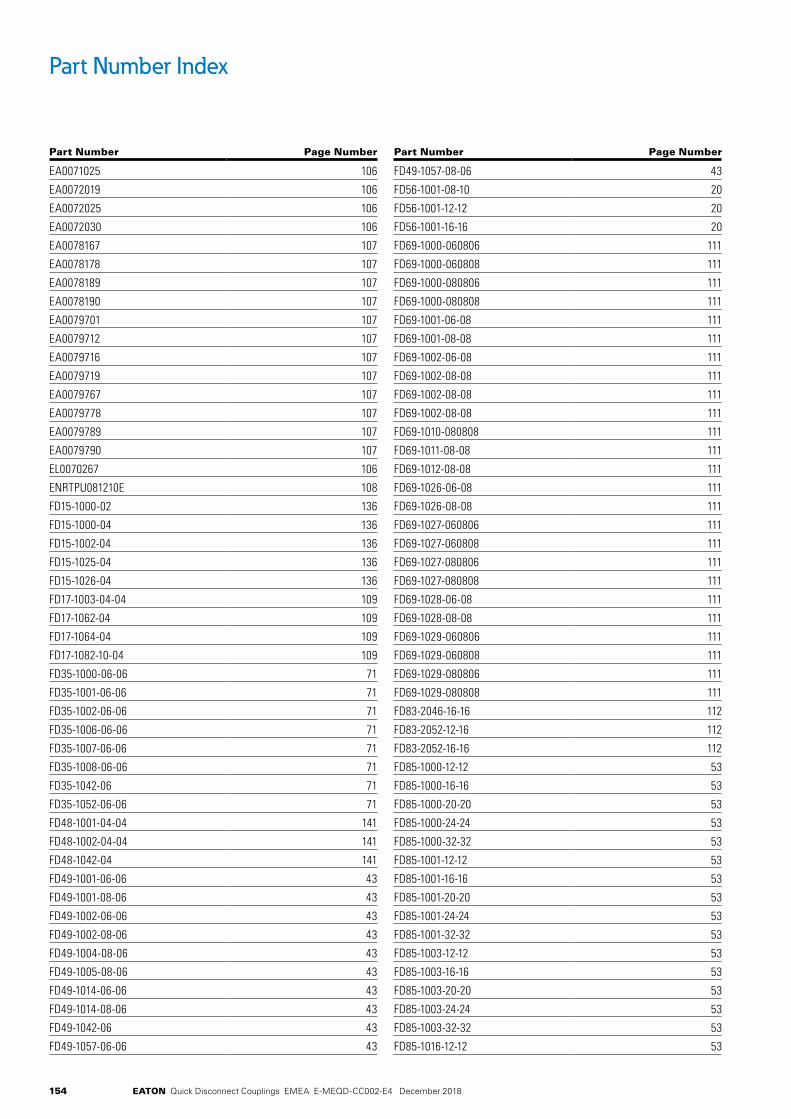
154 EATON Quick Disconnect Couplings EMEA E-MEQD-CC002-E4 December 2018
Part Number Index
Part Number Page Number
EA0071025 106
EA0072019 106
EA0072025 106
EA0072030 106
EA0078167 107
EA0078178 107
EA0078189 107
EA0078190 107
EA0079701 107
EA0079712 107
EA0079716 107
EA0079719 107
EA0079767 107
EA0079778 107
EA0079789 107
EA0079790 107
EL0070267 106
ENRTPU081210E 108
FD15-1000-02 136
FD15-1000-04 136
FD15-1002-04 136
FD15-1025-04 136
FD15-1026-04 136
FD17-1003-04-04 109
FD17-1062-04 109
FD17-1064-04 109
FD17-1082-10-04 109
FD35-1000-06-06 71
FD35-1001-06-06 71
FD35-1002-06-06 71
FD35-1006-06-06 71
FD35-1007-06-06 71
FD35-1008-06-06 71
FD35-1042-06 71
FD35-1052-06-06 71
FD48-1001-04-04 141
FD48-1002-04-04 141
FD48-1042-04 141
FD49-1001-06-06 43
FD49-1001-08-06 43
FD49-1002-06-06 43
FD49-1002-08-06 43
FD49-1004-08-06 43
FD49-1005-08-06 43
FD49-1014-06-06 43
FD49-1014-08-06 43
FD49-1042-06 43
FD49-1057-06-06 43
Part Number Page Number
FD49-1057-08-06 43
FD56-1001-08-10 20
FD56-1001-12-12 20
FD56-1001-16-16 20
FD69-1000-060806 111
FD69-1000-060808 111
FD69-1000-080806 111
FD69-1000-080808 111
FD69-1001-06-08 111
FD69-1001-08-08 111
FD69-1002-06-08 111
FD69-1002-08-08 111
FD69-1002-08-08 111
FD69-1002-08-08 111
FD69-1010-080808 111
FD69-1011-08-08 111
FD69-1012-08-08 111
FD69-1026-06-08 111
FD69-1026-08-08 111
FD69-1027-060806 111
FD69-1027-060808 111
FD69-1027-080806 111
FD69-1027-080808 111
FD69-1028-06-08 111
FD69-1028-08-08 111
FD69-1029-060806 111
FD69-1029-060808 111
FD69-1029-080806 111
FD69-1029-080808 111
FD83-2046-16-16 112
FD83-2052-12-16 112
FD83-2052-16-16 112
FD85-1000-12-12 53
FD85-1000-16-16 53
FD85-1000-20-20 53
FD85-1000-24-24 53
FD85-1000-32-32 53
FD85-1001-12-12 53
FD85-1001-16-16 53
FD85-1001-20-20 53
FD85-1001-24-24 53
FD85-1001-32-32 53
FD85-1003-12-12 53
FD85-1003-16-16 53
FD85-1003-20-20 53
FD85-1003-24-24 53
FD85-1003-32-32 53
FD85-1016-12-12 53
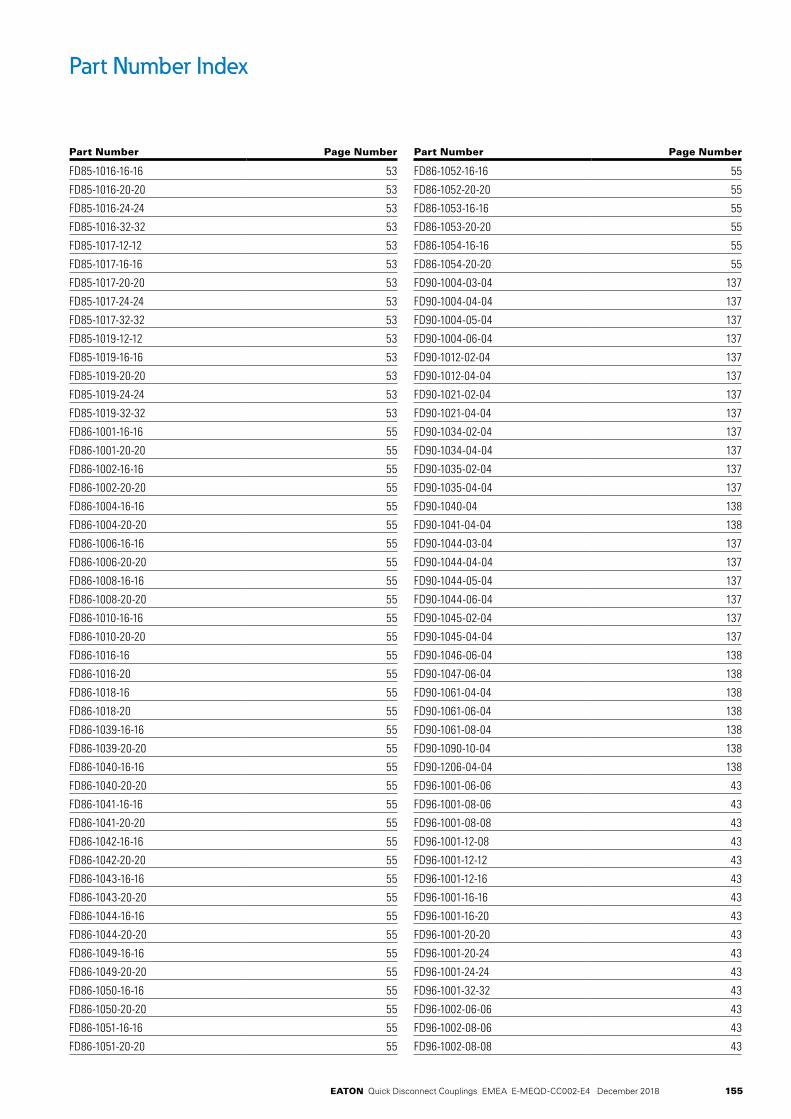
155EATON Quick Disconnect Couplings EMEA E-MEQD-CC002-E4 December 2018
Part Number Index
Part Number Page Number
FD85-1016-16-16 53
FD85-1016-20-20 53
FD85-1016-24-24 53
FD85-1016-32-32 53
FD85-1017-12-12 53
FD85-1017-16-16 53
FD85-1017-20-20 53
FD85-1017-24-24 53
FD85-1017-32-32 53
FD85-1019-12-12 53
FD85-1019-16-16 53
FD85-1019-20-20 53
FD85-1019-24-24 53
FD85-1019-32-32 53
FD86-1001-16-16 55
FD86-1001-20-20 55
FD86-1002-16-16 55
FD86-1002-20-20 55
FD86-1004-16-16 55
FD86-1004-20-20 55
FD86-1006-16-16 55
FD86-1006-20-20 55
FD86-1008-16-16 55
FD86-1008-20-20 55
FD86-1010-16-16 55
FD86-1010-20-20 55
FD86-1016-16 55
FD86-1016-20 55
FD86-1018-16 55
FD86-1018-20 55
FD86-1039-16-16 55
FD86-1039-20-20 55
FD86-1040-16-16 55
FD86-1040-20-20 55
FD86-1041-16-16 55
FD86-1041-20-20 55
FD86-1042-16-16 55
FD86-1042-20-20 55
FD86-1043-16-16 55
FD86-1043-20-20 55
FD86-1044-16-16 55
FD86-1044-20-20 55
FD86-1049-16-16 55
FD86-1049-20-20 55
FD86-1050-16-16 55
FD86-1050-20-20 55
FD86-1051-16-16 55
FD86-1051-20-20 55
Part Number Page Number
FD86-1052-16-16 55
FD86-1052-20-20 55
FD86-1053-16-16 55
FD86-1053-20-20 55
FD86-1054-16-16 55
FD86-1054-20-20 55
FD90-1004-03-04 137
FD90-1004-04-04 137
FD90-1004-05-04 137
FD90-1004-06-04 137
FD90-1012-02-04 137
FD90-1012-04-04 137
FD90-1021-02-04 137
FD90-1021-04-04 137
FD90-1034-02-04 137
FD90-1034-04-04 137
FD90-1035-02-04 137
FD90-1035-04-04 137
FD90-1040-04 138
FD90-1041-04-04 138
FD90-1044-03-04 137
FD90-1044-04-04 137
FD90-1044-05-04 137
FD90-1044-06-04 137
FD90-1045-02-04 137
FD90-1045-04-04 137
FD90-1046-06-04 138
FD90-1047-06-04 138
FD90-1061-04-04 138
FD90-1061-06-04 138
FD90-1061-08-04 138
FD90-1090-10-04 138
FD90-1206-04-04 138
FD96-1001-06-06 43
FD96-1001-08-06 43
FD96-1001-08-08 43
FD96-1001-12-08 43
FD96-1001-12-12 43
FD96-1001-12-16 43
FD96-1001-16-16 43
FD96-1001-16-20 43
FD96-1001-20-20 43
FD96-1001-20-24 43
FD96-1001-24-24 43
FD96-1001-32-32 43
FD96-1002-06-06 43
FD96-1002-08-06 43
FD96-1002-08-08 43

156 EATON Quick Disconnect Couplings EMEA E-MEQD-CC002-E4 December 2018
Part Number Index
Part Number Page Number
FD96-1002-12-08 43
FD96-1002-12-12 43
FD96-1002-12-16 43
FD96-1002-16-16 43
FD96-1002-16-20 43
FD96-1002-20-20 43
FD96-1002-20-24 43
FD96-1002-24-24 43
FD96-1002-32-32 43
FD96-1004-06-04 43
FD96-1004-08-06 43
FD96-1004-12-08 43
FD96-1004-12-12 43
FD96-1004-12-16 43
FD96-1004-16-16 43
FD96-1004-16-20 43
FD96-1004-20-20 43
FD96-1004-20-24 43
FD96-1004-24-24 43
FD96-1004-32-32 43
FD96-1005-06-04 43
FD96-1005-08-06 43
FD96-1005-12-08 43
FD96-1005-12-12 43
FD96-1005-12-16 43
FD96-1005-16-16 43
FD96-1005-16-20 43
FD96-1005-20-20 43
FD96-1005-20-24 43
FD96-1005-24-24 43
FD96-1005-32-32 43
FD96-1009-04 43
FD96-1009-06 43
FD96-1009-08 43
FD96-1009-12 43
FD96-1009-16 43
FD96-1009-20 43
FD96-1009-24 43
FD96-1009-32 43
FD96-1010-04 43
FD96-1010-06 43
FD96-1010-08 43
FD96-1010-12 43
FD96-1010-16 43
FD96-1010-20 43
FD96-1010-24 43
FD96-1010-32 43
FF098-04 51
Part Number Page Number
FF098-08 51
FF098-12 51
FF098-16 51
FF098-20 51
FF098-24 51
FF10166 111
FF10593-16 55
FF10593-20 55
FF10594-16 55
FF10594-20 55
FF10595-16 55
FF10595-20 55
FF10596-16 55
FF10596-20 55
FF10597-16 55
FF10597-20 55
FF10598-16 55
FF10598-20 55
FF91178–10 145
FF91178–112 145
FF91178–116 145
FF91178–214 145
GA0066174 75, 90
GA0066184 75, 90
GA0066185 75, 90
GA0066196 75, 90
GA0066214 75, 90
GA0066238 75, 90
GA0066245 75, 90
GA0066248 75, 90
GA0066314 75, 90
GA0066318 75, 90
GA0066338 75, 90
GA0066345 75, 90
GA0066701 75, 90
GA0066767 75, 90
GA0066778 75, 90
GA0066789 75, 90
GA0066790 75, 90
GA0066814 75, 90
GA0066845 75, 90
GA0076212 92
GA0076214 92
GA0076238 92
GA0076312 92
GA0076314 92
GA0076338 92
GA0076701 92

157EATON Quick Disconnect Couplings EMEA E-MEQD-CC002-E4 December 2018
Part Number Index
Part Number Page Number
GA0076713 92
GA0076767 92
GA0076789 92
GA90090-12 61
GA90090-16 61
GA90090-8 61
GA90091-12 61
GA90091-16 61
GA90091-8 61
GA90092-12 61
GA90092-16 61
GA90092-8 61
GA90762-12 61
GA90762-8 61
GA90763-12 61
GA90763-8 61
GA90767-12-16 61
GA90767-16-20 61
GA90767-8 61
GA90768-12-16 61
GA90768-16-20 61
GA90768-8 61
GD1052612 74
GD1052614 74
GD1052621 74
GD1052638 74
GD1052641 74
GD1052683 74
GD1053612 74
GD1053613 74
GD1053614 74
GD1053615 74
GD1053621 74
GD1053638 74
GD1053639 74
GD1053641 74
GD1053683 74
GD1055601 74
GD1055667 74
GD1055678 74
GD1055689 74
GD1055690 74
GD1852612 79
GD1852614 79
GD1852638 79
GD1853612 79
GD1853613 79
GD1853614 79
Part Number Page Number
GD1853615 79
GD1853638 79
GD1853639 79
GD1855014 79
GD1855038 79
GD1855601 79
GD1855613 79
GD1855667 79
GD1855678 79
GD1855689 79
GD1855690 79
GK1866214 79
GK1866218 79
GK1866238 79
GK1866241 79
GK1866245 79
GK1866281 79
GK1866314 79
GK1866315 79
GK1866318 79
GK1866319 79
GK1866338 79
GK1866339 79
GK1866341 79
GK1866381 79
GK1866701 79
GK1866713 79
GK1866767 79
GK1866778 79
GK1866789 79
GK1866790 79
GL0061674 89
GL0061684 89
GL0061685 89
GL0061696 89
GL0062614 89
GL0062638 89
GL0062645 89
GL0063612 89
GL0063614 89
GL0063638 89
GL0063645 89
GL0065014 89
GL0065601 89
GL0065667 89
GL0065678 89
GL0065689 89
GL0065690 89
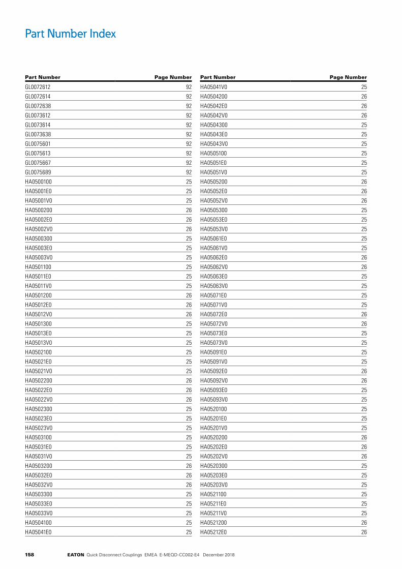
158 EATON Quick Disconnect Couplings EMEA E-MEQD-CC002-E4 December 2018
Part Number Index
Part Number Page Number
GL0072612 92
GL0072614 92
GL0072638 92
GL0073612 92
GL0073614 92
GL0073638 92
GL0075601 92
GL0075613 92
GL0075667 92
GL0075689 92
HA0500100 25
HA05001E0 25
HA05001V0 25
HA0500200 26
HA05002E0 26
HA05002V0 26
HA0500300 25
HA05003E0 25
HA05003V0 25
HA0501100 25
HA05011E0 25
HA05011V0 25
HA0501200 26
HA05012E0 26
HA05012V0 26
HA0501300 25
HA05013E0 25
HA05013V0 25
HA0502100 25
HA05021E0 25
HA05021V0 25
HA0502200 26
HA05022E0 26
HA05022V0 26
HA0502300 25
HA05023E0 25
HA05023V0 25
HA0503100 25
HA05031E0 25
HA05031V0 25
HA0503200 26
HA05032E0 26
HA05032V0 26
HA0503300 25
HA05033E0 25
HA05033V0 25
HA0504100 25
HA05041E0 25
Part Number Page Number
HA05041V0 25
HA0504200 26
HA05042E0 26
HA05042V0 26
HA0504300 25
HA05043E0 25
HA05043V0 25
HA0505100 25
HA05051E0 25
HA05051V0 25
HA0505200 26
HA05052E0 26
HA05052V0 26
HA0505300 25
HA05053E0 25
HA05053V0 25
HA05061E0 25
HA05061V0 25
HA05062E0 26
HA05062V0 26
HA05063E0 25
HA05063V0 25
HA05071E0 25
HA05071V0 25
HA05072E0 26
HA05072V0 26
HA05073E0 25
HA05073V0 25
HA05091E0 25
HA05091V0 25
HA05092E0 26
HA05092V0 26
HA05093E0 25
HA05093V0 25
HA0520100 25
HA05201E0 25
HA05201V0 25
HA0520200 26
HA05202E0 26
HA05202V0 26
HA0520300 25
HA05203E0 25
HA05203V0 25
HA0521100 25
HA05211E0 25
HA05211V0 25
HA0521200 26
HA05212E0 26
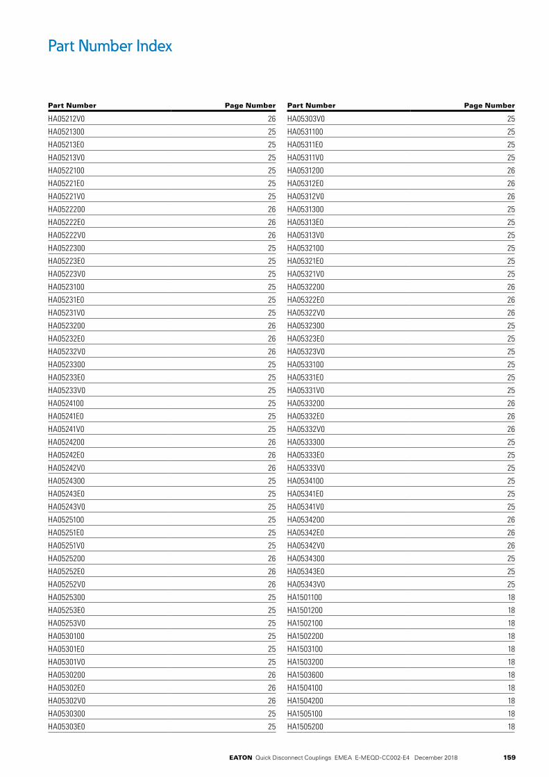
159EATON Quick Disconnect Couplings EMEA E-MEQD-CC002-E4 December 2018
Part Number Index
Part Number Page Number
HA05212V0 26
HA0521300 25
HA05213E0 25
HA05213V0 25
HA0522100 25
HA05221E0 25
HA05221V0 25
HA0522200 26
HA05222E0 26
HA05222V0 26
HA0522300 25
HA05223E0 25
HA05223V0 25
HA0523100 25
HA05231E0 25
HA05231V0 25
HA0523200 26
HA05232E0 26
HA05232V0 26
HA0523300 25
HA05233E0 25
HA05233V0 25
HA0524100 25
HA05241E0 25
HA05241V0 25
HA0524200 26
HA05242E0 26
HA05242V0 26
HA0524300 25
HA05243E0 25
HA05243V0 25
HA0525100 25
HA05251E0 25
HA05251V0 25
HA0525200 26
HA05252E0 26
HA05252V0 26
HA0525300 25
HA05253E0 25
HA05253V0 25
HA0530100 25
HA05301E0 25
HA05301V0 25
HA0530200 26
HA05302E0 26
HA05302V0 26
HA0530300 25
HA05303E0 25
Part Number Page Number
HA05303V0 25
HA0531100 25
HA05311E0 25
HA05311V0 25
HA0531200 26
HA05312E0 26
HA05312V0 26
HA0531300 25
HA05313E0 25
HA05313V0 25
HA0532100 25
HA05321E0 25
HA05321V0 25
HA0532200 26
HA05322E0 26
HA05322V0 26
HA0532300 25
HA05323E0 25
HA05323V0 25
HA0533100 25
HA05331E0 25
HA05331V0 25
HA0533200 26
HA05332E0 26
HA05332V0 26
HA0533300 25
HA05333E0 25
HA05333V0 25
HA0534100 25
HA05341E0 25
HA05341V0 25
HA0534200 26
HA05342E0 26
HA05342V0 26
HA0534300 25
HA05343E0 25
HA05343V0 25
HA1501100 18
HA1501200 18
HA1502100 18
HA1502200 18
HA1503100 18
HA1503200 18
HA1503600 18
HA1504100 18
HA1504200 18
HA1505100 18
HA1505200 18

160 EATON Quick Disconnect Couplings EMEA E-MEQD-CC002-E4 December 2018
Part Number Index
Part Number Page Number
HA1521100 18
HA1521200 18
HA1522100 18
HA1522200 18
HA1523100 18
HA1523200 18
HA1524100 18
HA1524200 18
HA1525100 18
HA1525200 18
HA5502100 144
HA5502200 144
HA5503100 144
HA5503200 144
HD0510100 26, 29, 32, 122, 125, 128
HD0510200 26, 29, 32, 122, 125, 128
HD0511100 26, 29, 32, 122, 125, 128
HD0511200 26, 29, 32, 122, 125, 128
HD0512100 26, 29, 32, 122, 125, 128
HD0512200 26, 29, 32, 122, 125, 128
HD0513100 26, 29, 32, 122, 125, 128
HD0513200 26, 29, 32, 122, 125, 128
HD0514100 26, 29, 32, 122, 125, 128
HD0514200 26, 29, 32, 122, 125, 128
HD0515100 26, 29, 32, 122, 125, 128
HD0515200 26, 29, 32, 122, 125, 128
HD0516100 26, 29, 32, 122, 125, 128
HD0516200 26, 29, 32, 122, 125, 128
HD0517100 26, 29, 32, 122, 125, 128
HD0517200 26, 29, 32, 122, 125, 128
HD0519100 26, 29, 32, 122, 125, 128
HD0519200 26, 29, 32, 122, 125, 128
HL0500100 28
HL05001E0 28
HL05001V0 28
HL0500200 29
HL05002E0 29
HL05002V0 29
HL0500300 28
HL05003E0 28
HL05003V0 28
HL0501100 28
HL05011E0 28
HL05011V0 28
HL0501200 29
HL05012E0 29
HL05012V0 29
HL0501300 28
Part Number Page Number
HL05013E0 28
HL05013V0 28
HL0502100 28
HL05021E0 28
HL05021V0 28
HL0502200 29
HL05022E0 29
HL05022V0 29
HL0502300 28
HL05023E0 28
HL05023V0 28
HL0503100 28
HL05031E0 28
HL05031V0 28
HL0503200 29
HL05032E0 29
HL05032V0 29
HL0503300 28
HL05033E0 28
HL05033V0 28
HL0504100 28
HL05041E0 28
HL05041V0 28
HL0504200 29
HL05042E0 29
HL05042V0 29
HL0504300 28
HL05043E0 28
HL05043V0 28
HL0505100 28
HL05051E0 28
HL05051V0 28
HL0505200 29
HL05052E0 29
HL05052V0 29
HL0505300 28
HL05053E0 28
HL05053V0 28
HL0506100 28
HL05061E0 28
HL05061V0 28
HL05062E0 29
HL05062V0 29
HL0506300 28
HL05063E0 28
HL05063V0 28
HL0507100 28
HL05071E0 28
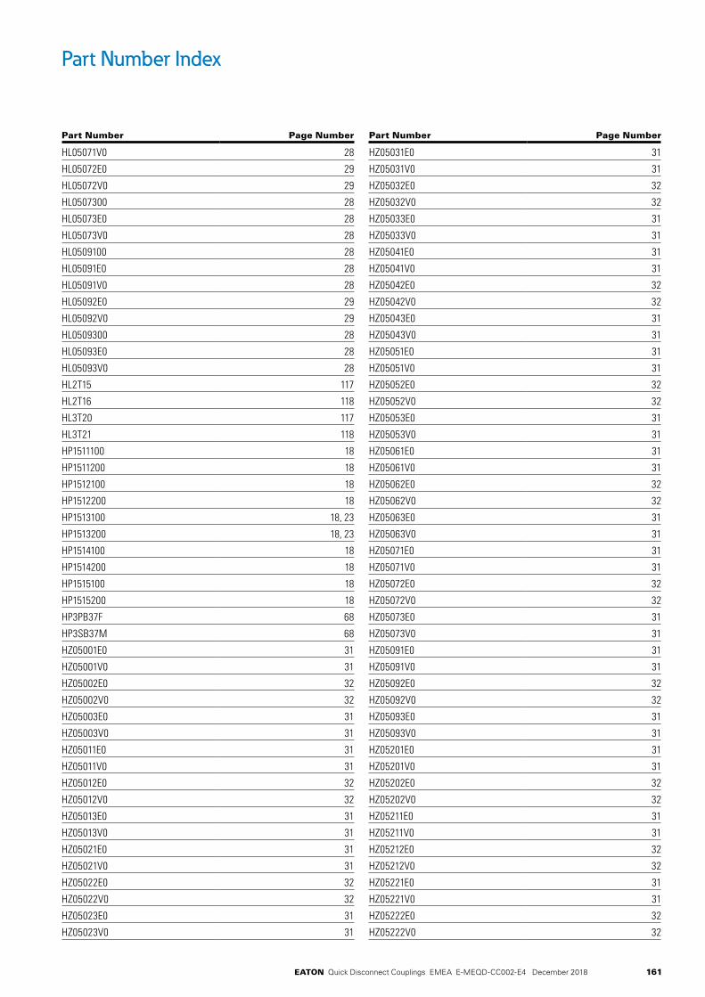
161EATON Quick Disconnect Couplings EMEA E-MEQD-CC002-E4 December 2018
Part Number Index
Part Number Page Number
HL05071V0 28
HL05072E0 29
HL05072V0 29
HL0507300 28
HL05073E0 28
HL05073V0 28
HL0509100 28
HL05091E0 28
HL05091V0 28
HL05092E0 29
HL05092V0 29
HL0509300 28
HL05093E0 28
HL05093V0 28
HL2T15 117
HL2T16 118
HL3T20 117
HL3T21 118
HP1511100 18
HP1511200 18
HP1512100 18
HP1512200 18
HP1513100 18, 23
HP1513200 18, 23
HP1514100 18
HP1514200 18
HP1515100 18
HP1515200 18
HP3PB37F 68
HP3SB37M 68
HZ05001E0 31
HZ05001V0 31
HZ05002E0 32
HZ05002V0 32
HZ05003E0 31
HZ05003V0 31
HZ05011E0 31
HZ05011V0 31
HZ05012E0 32
HZ05012V0 32
HZ05013E0 31
HZ05013V0 31
HZ05021E0 31
HZ05021V0 31
HZ05022E0 32
HZ05022V0 32
HZ05023E0 31
HZ05023V0 31
Part Number Page Number
HZ05031E0 31
HZ05031V0 31
HZ05032E0 32
HZ05032V0 32
HZ05033E0 31
HZ05033V0 31
HZ05041E0 31
HZ05041V0 31
HZ05042E0 32
HZ05042V0 32
HZ05043E0 31
HZ05043V0 31
HZ05051E0 31
HZ05051V0 31
HZ05052E0 32
HZ05052V0 32
HZ05053E0 31
HZ05053V0 31
HZ05061E0 31
HZ05061V0 31
HZ05062E0 32
HZ05062V0 32
HZ05063E0 31
HZ05063V0 31
HZ05071E0 31
HZ05071V0 31
HZ05072E0 32
HZ05072V0 32
HZ05073E0 31
HZ05073V0 31
HZ05091E0 31
HZ05091V0 31
HZ05092E0 32
HZ05092V0 32
HZ05093E0 31
HZ05093V0 31
HZ05201E0 31
HZ05201V0 31
HZ05202E0 32
HZ05202V0 32
HZ05211E0 31
HZ05211V0 31
HZ05212E0 32
HZ05212V0 32
HZ05221E0 31
HZ05221V0 31
HZ05222E0 32
HZ05222V0 32

162 EATON Quick Disconnect Couplings EMEA E-MEQD-CC002-E4 December 2018
Part Number Index
Part Number Page Number
HZ05231E0 31
HZ05231V0 31
HZ05232E0 32
HZ05232V0 32
HZ05241E0 31
HZ05241V0 31
HZ05242E0 32
HZ05242V0 32
HZ05251E0 31
HZ05251V0 31
HZ05252E0 32
HZ05252V0 32
IA0090612 77, 94
IA0090614 77, 94
IA0090638 77, 94
IA0090712 77, 94
IA0090714 77, 94
IA0090738 77, 94
IA0090901 77, 94
IA0090912 77, 94
IA0090978 77, 94
IA0090989 77, 94
IA0090990 77, 94
IA0100612 96
IA0100638 96
IA0100712 96
IA0100738 96
IA0100901 96
IA0100912 96
IA0100990 96
ID1095601 77
ID1095678 77
ID1095689 77
ID1095690 77
ID1096012 77
ID1096013 77
ID1096014 77
ID1096015 77
ID1096021 77
ID1096038 77
ID1096039 77
ID1096041 77
ID1096083 77
ID1097012 77
ID1097014 77
ID1097021 77
ID1097038 77
ID1097041 77
Part Number Page Number
ID1097083 77
ID1895012 81
ID1895038 81
ID1895601 81
ID1895613 81
ID1895689 81
ID1895690 81
ID1896012 81
ID1896013 81
ID1896014 81
ID1896015 81
ID1896038 81
ID1896039 81
ID1897012 81
ID1897014 81
ID1897038 81
IK1890612 81
IK1890613 81
IK1890614 81
IK1890615 81
IK1890638 81
IK1890639 81
IK1890641 81
IK1890683 81
IK1890712 81
IK1890714 81
IK1890738 81
IK1890741 81
IK1890783 81
IK1890901 81
IK1890913 81
IK1890989 81
IK1890990 81
IL0095601 94
IL0095689 94
IL0095690 94
IL0096012 94
IL0096014 94
IL0096038 94
IL0097012 94
IL0097014 94
IL0097038 94
IL0105601 96
IL0105689 96
IL0105690 96
IL0106012 96
IL0106014 96
IL0106038 96

163EATON Quick Disconnect Couplings EMEA E-MEQD-CC002-E4 December 2018
Part Number Index
Part Number Page Number
IL0107012 96
IL0107014 96
IL0107038 96
J62P082 120
J62P083 120
J62P122 120
J62P123 120
JL7083114 120
JL7083118 120
JL7083214 120
JL7083218 120
JL7083314 120
JL7083318 120
JL7083414 120
JL7083614 120
JL7083618 120
JL7083638 120
JL7086214 120
JL7086701 119
JL7086712 119
JL7086789 119
JL7086812 120
JL7086838 120
JL7088201 119
JL7088212 119
JL7088289 119
JL7088301 120
JL7088312 120
JL7088389 120
JL7123612 120
JL7123638 120
JL7126212 120
JL7126713 119
JL7126716 119
JX5062614 118
JX5067215 118
JX5068214 118
JX5092638 118
JX5097239 118
KA0802412 139
KA0812700 139
KA0832412 139
KA0832413 139
KA0832718 139
KP0812400 139
LA0700100 121
LA07001E0 121
LA07001V0 121
Part Number Page Number
LA0700200 121
LA0701100 121
LA07011E0 121
LA07011V0 121
LA0701200 121
LA0702100 121
LA07021E0 121
LA07021V0 121
LA0702200 121
LA0703100 121
LA07031E0 121
LA07031V0 121
LA0703200 121
LA0704100 121
LA07041E0 121
LA07041V0 121
LA0704200 121
LA0705100 121
LA07051E0 121
LA07051V0 121
LA0705200 121
LA07061E0 121
LA07061V0 121
LA0706200 121
LA07071E0 121
LA07071V0 121
LA0707200 121
LA07091E0 121
LA07091V0 121
LA0709200 121
LL0700100 124
LL07001E0 124
LL07001V0 124
LL0700200 124
LL0701100 124
LL07011E0 124
LL07011V0 124
LL0701200 124
LL0702100 124
LL07021E0 124
LL07021V0 124
LL0702200 124
LL0703100 124
LL07031E0 124
LL07031V0 124
LL0703200 124
LL0704100 124
LL07041E0 124

164 EATON Quick Disconnect Couplings EMEA E-MEQD-CC002-E4 December 2018
Part Number Index
Part Number Page Number
LL07041V0 124
LL0704200 124
LL0705100 124
LL07051E0 124
LL07051V0 124
LL0705200 124
LL07061E0 124
LL07061V0 124
LL0706200 124
LL07071E0 124
LL07071V0 124
LL0707200 124
LL07091E0 124
LL07091V0 124
LL0709200 124
LL10 85
LL1000 85
LL10H41 15
LL10H41BS 15
LL10K41 16
LL10K41BS 16
LL10S41 118
LL10T40 117
LL10T41 118
LL10T41BS 118
LL11 85
LL1100 85
LL12H41 15
LL12H41BS 15
LL12H46 15
LL12H46BS 15
LL12K41 16
LL12K41BS 16
LL12K46 16
LL12K46BS 16
LL12S46 118
LL12S46BS 118
LL12T46 118
LL12T46BS 118
LL16S51 118
LL16S51BS 118
LL16T50 117
LL1H11 15
LL1H4 15
LL1K11 16
LL1K4 16
LL1S10 117
LL1S11 118
Part Number Page Number
LL1S11BS 118
LL1S12 119
LL1S17 119
LL1T10 117
LL1T11 118
LL1T11BS 118
LL1T12 119
LL1T17 119
LL20H51 15
LL20H51BS 15
LL20H56 15
LL20H56BS 15
LL20H61 15
LL20H61BS 15
LL20K51 16
LL20K51BS 16
LL20K56 16
LL20K56BS 16
LL20K61 16
LL20K61BS 16
LL2H16 15
LL2H16BS 15
LL2H6 15
LL2K16 16
LL2K16BS 16
LL2K6 16
LL2S15 117
LL2S16 118
LL2S16BS 118
LL2S17 119
LL2T15 117
LL2T15BS 117
LL2T16 118
LL2T16BS 118
LL2T17 119
LL3H21 15
LL3H21BS 15
LL3H8 15
LL3K21 16
LL3K21BS 16
LL3K8 16
LL3S20 117
LL3S20BS 117
LL3S21 118
LL3S21BS 118
LL3S22 119
LL3T20 117
LL3T20BS 117
165EATON Quick Disconnect Couplings EMEA E-MEQD-CC002-E4 December 2018
Part Number Index
Part Number Page Number
LL3T21 118
LL3T21BS 118
LL3T22 119
LL4HP10 15
LL4HP26 15
LL4HP26BS 15
LL4KP10 16
LL4KP26 16
LL4KP26BS 16
LL4S25 117
LL4S25BS 117
LL4S26 118
LL4S26BS 118
LL4S27 119
LL4T25 117
LL4T25BS 117
LL4T26 118
LL4T26BS 118
LL4T27 119
LL6HP12 15
LL6HP31 15
LL6HP31BS 15
LL6KP12 16
LL6KP31 16
LL6KP31BS 16
LL6S30 117
LL6S31 118
LL6S31BS 118
LL6S32 119
LL6T30 117
LL6T30BS 117
LL6T31 118
LL6T31BS 118
LL6T32 119
LL8HP16 15
LL8HP36 15
LL8HP36BS 15
LL8KP16 16
LL8KP36 16
LL8KP36BS 16
LL8S36 118
LL8S36BS 118
LL8S37 119
LL8T35 117
LL8T36 118
LL8T36BS 118
LZ07001E0 127
LZ07001V0 127
Part Number Page Number
LZ0700200 127
LZ07011E0 127
LZ07011V0 127
LZ0701200 127
LZ07021E0 127
LZ07021V0 127
LZ0702200 127
LZ07031E0 127
LZ07031V0 127
LZ0703200 127
LZ07041E0 127
LZ07041V0 127
LZ0704200 127
LZ07051E0 127
LZ07051V0 127
LZ0705200 127
LZ07061E0 127
LZ07061V0 127
LZ0706200 127
LZ07071E0 127
LZ07071V0 127
LZ0707200 127
LZ07091E0 127
LZ07091V0 127
LZ0709200 127
MA0024145 102
MA0024188 102
MA0024214 103
MA0024228 103
MA0024242 103
MA0024248 103
MA0024284 103
MA0024310 102
MA0024312 102
MA0024314 102
MA0024318 102
MA0024334 102
MA0024338 102
MA0024424 102
MA0024441 102
MA0024448 102
MA0024482 102
MA0024484 102
MA0024512 102
MA0024524 102
MA0024548 102
MA0024588 102
MA0024610 104

166 EATON Quick Disconnect Couplings EMEA E-MEQD-CC002-E4 December 2018
Part Number Index
Part Number Page Number
MA0024612 104
MA0024614 104
MA0024618 104
MA0024634 104
MA0024638 104
MA0025514 103
MA0025528 103
MA0025542 103
MA0025548 103
MA0025584 103
MA0025612 103
MA0025624 103
MA0025648 103
MA0025688 103
MA0026610 104
MA0026612 104
MA0026614 104
MA0026618 104
MA0026634 104
MA0026638 104
MA0026714 104
MA0026728 104
MA0026742 104
MA0026748 104
MA0026784 104
MA0026812 103
MA0026824 103
MA0026848 103
MA0026888 103
MA0026910 104
MA0026912 104
MA0026914 104
MA0026918 104
MA0026934 104
MA0026938 106
MA0027828 103
MA0027842 103
MA0027848 103
MA0027884 103
ML0028010 105
ML0028012 105
ML0028014 105
ML0028018 105
ML0028034 105
ML0028038 105
ML0028112 105
ML0028114 105
ML0028118 105
Part Number Page Number
ML0028138 105
ML0028210 105
ML0028212 105
ML0028214 105
ML0028218 105
ML0028234 105
ML0028238 105
ML0028410 106
ML0028412 106
ML0028414 106
ML0028418 106
ML0028434 106
ML0028438 106
ML0028612 105
ML0028614 105
ML0028618 105
ML0028638 105
ML10FFP37 39
ML10FFP37143 39
ML10FFP37192 39
ML10FFP37BS 39
ML10FFP37BS143 39
ML10FFP37BS192 39
ML10FFP50BS 39
ML10FFP50BS143 39
ML10FFP50BS192 39
ML10FFS37 39
ML10FFS37143 39
ML10FFS37192 39
ML10FFS37BS 39
ML10FFS37BS143 39
ML10FFS37BS192 39
ML10FFS50BS 39
ML10FFS50BS143 39
ML10FFS50BS192 39
ML12FFP50 39
ML12FFP50143 39
ML12FFP50192 39
ML12FFP50BS 39
ML12FFP50BS143 39
ML12FFP50BS192 39
ML12FFP75BS 39
ML12FFP75BS143 39
ML12FFP75BS192 39
ML12FFS50 39
ML12FFS50143 39
ML12FFS50192 39
ML12FFS50BS 39

167EATON Quick Disconnect Couplings EMEA E-MEQD-CC002-E4 December 2018
Part Number Index
Part Number Page Number
ML12FFS50BS143 39
ML12FFS50BS192 39
ML12FFS75BS 39
ML12FFS75BS143 39
ML12FFS75BS192 39
ML16FFP75 39
ML16FFP75143 39
ML16FFP75192 39
ML16FFP75BS 39
ML16FFP75BS143 39
ML16FFP75BS192 39
ML16FFS75 39
ML16FFS75143 39
ML16FFS75192 39
ML16FFS75BS 39
ML16FFS75BS143 39
ML16FFS75BS192 39
ML19FFP100 39
ML19FFP100143 39
ML19FFP100192 39
ML19FFP100BS 39
ML19FFP100BS143 39
ML19FFP100BS192 39
ML19FFP75 39
ML19FFP75143 39
ML19FFP75192 39
ML19FFP75BS 39
ML19FFP75BS143 39
ML19FFP75BS192 39
ML19FFS100 39
ML19FFS100143 39
ML19FFS100192 39
ML19FFS100BS 39
ML19FFS100BS143 39
ML19FFS100BS192 39
ML19FFS75 39
ML19FFS75143 39
ML19FFS75192 39
ML19FFS75BS 39
ML19FFS75BS143 39
ML19FFS75BS192 39
ML1H11 15
ML1K11 16
ML25FFP100BS 39
ML25FFP100BS143 39
ML25FFP100BS192 39
ML25FFP125 39
ML25FFP125143 39
Part Number Page Number
ML25FFP125192 39
ML40FFP150 39
ML40FFP150143 39
ML40FFP150BS 39
ML50FFP200143 39
ML25FFS100BS 39
ML25FFS100BS143 39
ML25FFS100BS192 39
ML25FFS125 39
ML25FFS125143 39
ML25FFS125192 39
ML40FFS150 39
ML40FFS150143 39
ML40FFS150BS 39
ML50FFS200143 39
ML2DBP25F 45
ML2DBP25F242 45
ML2DBP25F292 45
ML2DBP25F503 45
ML2DBP25FBS 45
ML2DBP25FBS242 45
ML2DBP25FBS292 45
ML2DBP25FBS503 45
ML2DBS25F 45
ML2DBS25F242 45
ML2DBS25F292 45
ML2DBS25F503 45
ML2DBS25FBS 45
ML2DBS25FBS242 45
ML2DBS25FBS292 45
ML2DBS25FBS503 45
ML2DBS93 45
ML2H16 15
ML2H16BS 15
ML2K16 16
ML2K16BS 16
ML2K16C 16
ML3H21 15
ML3H21BS 15
ML3K21BS 16
ML3K21C 16
ML4DBP50F 45
ML4DBP50F242 45
ML4DBP50F292 45
ML4DBP50F503 45
ML4DBP50FBS 45
ML4DBP50FBS242 45
ML4DBP50FBS292 45
168 EATON Quick Disconnect Couplings EMEA E-MEQD-CC002-E4 December 2018
Part Number Index
Part Number Page Number
ML4DBP50FBS503 45
ML4DBS50F 45
ML4DBS50F242 45
ML4DBS50F292 45
ML4DBS50F503 45
ML4DBS50FBS 45
ML4DBS50FBS242 45
ML4DBS50FBS292 45
ML4DBS50FBS503 45
ML4DBS93 45
ML4HP26 15
ML4HP26BS 15
ML4KP26 16
ML4KP26BS 16
ML50FFP200143 39
ML50FFS200143 39
ML6DBP75F 45
ML6DBP75F242 45
ML6DBP75F292 45
ML6DBP75F503 45
ML6DBP75FBS 45
ML6DBP75FBS242 45
ML6DBP75FBS292 45
ML6DBP75FBS503 45
ML6DBS75F 45
ML6DBS75F242 45
ML6DBS75F292 45
ML6DBS75F503 45
ML6DBS75FBS 45
ML6DBS75FBS242 45
ML6DBS75FBS292 45
ML6DBS75FBS503 45
ML6DBS93 45
ML6FFP25 39
ML6FFP25143 39
ML6FFP25192 39
ML6FFP25BS 39
ML6FFP25BS143 39
ML6FFP25BS192 39
ML6FFS25 39
ML6FFS25143 39
ML6FFS25192 39
ML6FFS25BS 39
ML6FFS25BS143 39
ML6FFS25BS192 39
ML6HP31 15
ML6HP31BS 15
ML6KP31 16
Part Number Page Number
ML6KP31BS 16
ML8DBP100F 45
ML8DBP100F242 45
ML8DBP100F292 45
ML8DBP100F503 45
ML8DBP100FBS 45
ML8DBP100FBS242 45
ML8DBP100FBS292 45
ML8DBP100FBS503 45
ML8DBS100F 45
ML8DBS100F242 45
ML8DBS100F292 45
ML8DBS100F503 45
ML8DBS100FBS 45
ML8DBS100FBS242 45
ML8DBS100FBS292 45
ML8DBS100FBS503 45
ML8DBS93 45
ML8HP36 15
ML8HP36BS 15
ML8KP36 16
ML8KP36BS 16
PDC10FF 37
PDC12FF 37
PDC12HK 10, 13, 16
PDC16FF 37
PDC19FF 37
PDC1HK 10, 13, 16
PDC20HK 10, 13, 16
PDC25FF 37
PDC2HK 10, 13, 16
PDC3HK 10, 13, 16
PDC4HK 10, 13, 16
PDC6FF 37
PDC6HK 10, 13, 16
PDC8HK 10, 13, 16
PPDC1HK 10, 13, 16
PPDC2HK 10, 13, 16
PPDC2UH 72
PPDC3HK 10, 13, 16
PPDC4HK 124
PPDC4HK(RD) 10, 13, 16
PPDC6HK 124
PPDC6HK(RD) 10, 13, 16
PPDC8HK 124
PPDC8HK(RD) 10, 13, 16
PSDC1HK 10, 13, 16
PSDC1HK 119

169EATON Quick Disconnect Couplings EMEA E-MEQD-CC002-E4 December 2018
Part Number Index
Part Number Page Number
PSDC2HK 10, 13, 16
PSDC2HK 119
PSDC2UH 72
PSDC3HK 10, 13, 16
PSDC4HK 119
PSDC4HK(RD) 10, 13, 16
PSDC6HK(RD) 10, 13, 16
PSDC8HK(RD) 10, 13, 16
QA0912100 140
QA0932118 140
QA0932212 140
QA0932213 140
QP0912200 140
RA0400000 130
RA040000B 130
RA04000E0 130
RA04000EB 130
RA04000V0 130
RA04000VB 130
RA0401000 130
RA040100B 130
RA04010E0 130
RA04010EB 130
RA04010V0 130
RA04010VB 130
RA0402000 130
RA040200B 130
RA04020E0 130
RA04020EB 130
RA04020V0 130
RA04020VB 130
RA0403000 130
RA040300B 130
RA04030E0 130
RA04030EB 130
RA04030V0 130
RA04030VB 130
RA0404000 130
RA040400B 130
RA04040E0 130
RA04040EB 130
RA04040V0 130
RA04040VB 130
RA0405000 130
RA040500B 130
RA04050E0 130
RA04050EB 130
RA04050V0 130
Part Number Page Number
RA04050VB 130
RA04060E0 130
RA04060EB 130
RA04060V0 130
RA04060VB 130
RA04070E0 130
RA04070EB 130
RA04070V0 130
RA04070VB 130
RA04090E0 130
RA04090EB 130
RA04090V0 130
RA04090VB 130
RL0400000 132
RL040000B 132
RL04000E0 132
RL04000EB 132
RL04000V0 132
RL04000VB 132
RL0401000 132
RL040100B 132
RL04010E0 132
RL04010EB 132
RL04010V0 132
RL04010VB 132
RL0402000 132
RL040200B 132
RL04020E0 132
RL04020EB 132
RL04020V0 132
RL04020VB 132
RL0403000 132
RL040300B 132
RL04030E0 132
RL04030EB 132
RL04030V0 132
RL04030VB 132
RL0404000 132
RL040400B 132
RL04040E0 132
RL04040EB 132
RL04040V0 132
RL04040VB 132
RL0405000 132
RL040500B 132
RL04050E0 132
RL04050EB 132
RL04050V0 132
170 EATON Quick Disconnect Couplings EMEA E-MEQD-CC002-E4 December 2018
Part Number Index
Part Number Page Number
RL04050VB 132
RL04060E0 132
RL04060EB 132
RL04060V0 132
RL04060VB 132
RL04070E0 132
RL04070EB 132
RL04070V0 132
RL04070VB 132
RL04090E0 132
RL04090EB 132
RL04090V0 132
RL04090VB 132
RZ04000E0 134
RZ04000EB 134
RZ04000V0 134
RZ04000VB 134
RZ04010E0 134
RZ04010EB 134
RZ04010V0 134
RZ04010VB 134
RZ04020E0 134
RZ04020EB 134
RZ04020V0 134
RZ04020VB 134
RZ04030E0 134
RZ04030EB 134
RZ04030V0 134
RZ04030VB 134
RZ04040E0 134
RZ04040EB 134
RZ04040V0 134
RZ04040VB 134
RZ04050E0 134
RZ04050EB 134
RZ04050V0 134
RZ04050VB 134
RZ04060E0 134
RZ04060EB 134
RZ04060V0 134
RZ04060VB 134
RZ04070E0 134
RZ04070EB 134
RZ04070V0 134
RZ04070VB 134
RZ04090E0 134
RZ04090EB 134
RZ04090V0 134
Part Number Page Number
RZ04090VB 134
SA0017014 101
SA0017514 101
SDC10FF 37
SDC12FF 37
SDC12HK 10, 13, 16
SDC16FF 37
SDC19FF 37
SDC1HK 10, 13, 16
SDC20HK 10, 13, 16
SDC25FF 37
SDC2HK 10, 13, 16
SDC3HK 10, 13, 16
SDC4HK 10, 13, 16
SDC6FF 37
SDC6HK 10, 13, 16
SDC8HK 10, 13, 16
SP0020014 101
SPUBD0584E 108
SPUBD65104E 108
TA0111512 98
TA0111538 98
TA0111612 98
TA0111638 98
TA0111813 98
TA0111816 98
TA0111819 98
TA0131512 100
TA0131538 100
TA0131612 100
TA0131638 100
TA0131813 100
TA0131816 100
TA0131819 100
TD1832012 83
TD1832034 83
TD1832112 83
TD1832134 83
TD1832138 83
TD1835012 83
TD1835034 83
TD1835601 83
TD1835613 83
TD1835616 83
TK1831512 83
TK1831534 83
TK1831539 83
TK1831612 83

171EATON Quick Disconnect Couplings EMEA E-MEQD-CC002-E4 December 2018
Part Number Index
Part Number Page Number
TK1831634 83
TK1831638 83
TK1831801 83
TK1831813 83
TK1831816 83
TK1831889 83
TL0112012 98
TL0112034 98
TL0112038 98
TL0112112 98
TL0112134 98
TL0112138 98
TL0115601 98
TL0115613 98
TL0115616 98
TL0132012 100
TL0132034 100
TL0132038 100
TL0132112 100
TL0132134 100
TL0132138 100
TL0135601 100
TL0135613 100
TL0135616 100
WA0601400 63
WA06014E0 63
WA06014V0 63
WA0601700 63
WA06017E0 63
WA06017V0 63
WA0602400 63
WA06024E0 63
WA06024V0 63
WA0602700 63
WA06027E0 63
WA06027V0 63
WA0603400 63
WA06034E0 63
WA06034V0 63
WA0603700 63
WA06037E0 63
WA06037V0 63
WA0604400 63
WA06044E0 63
WA06044V0 63
WA0604700 63
WA06047E0 63
WA06047V0 63
Part Number Page Number
WA0605400 63
WA06054E0 63
WA06054V0 63
WA0605700 63
WA06057E0 63
WA06057V0 63
WA0606400 63
WA06064E0 63
WA06064V0 63
WA0606700 63
WA06067E0 63
WA06067V0 63
WA0607400 63
WA06074E0 63
WA06074V0 63
WA0607700 63
WA06077E0 63
WA06077V0 63
WA0609400 63
WA06094E0 63
WA06094V0 63
WA0609700 63
WA06097E0 63
WA06097V0 63
WA0621400 63
WA06214E0 63
WA06214V0 63
WA0621700 63
WA06217E0 63
WA06217V0 63
WA0622400 63
WA06224E0 63
WA06224V0 63
WA0622700 63
WA06227E0 63
WA06227V0 63
WA0623400 63
WA06234E0 63
WA06234V0 63
WA0623700 63
WA06237E0 63
WA06237V0 63
WA0624400 63
WA06244E0 63
WA06244V0 63
WA0624700 63
WA06247E0 63
WA06247V0 63
172 EATON Quick Disconnect Couplings EMEA E-MEQD-CC002-E4 December 2018
Part Number Index
Part Number Page Number
WA0625400 63
WA06254E0 63
WA06254V0 63
WA0625700 63
WA06257E0 63
WA06257V0 63
WA0626400 63
WA06264E0 63
WA06264V0 63
WA0626700 63
WA06267E0 63
WA06267V0 63
WA0627400 63
WA06274E0 63
WA06274V0 63
WA0627700 63
WA06277E0 63
WA06277V0 63
WA0629400 63
WA06294E0 63
WA06294V0 63
WA0629700 63
WA06297E0 63
WA06297V0 63
WA0633400 63
WA06334E0 63
WA06334V0 63
WA0633700 63
WA06337E0 63
WA06337V0 63
WA0635400 63
WA06354E0 63
WA06354V0 63
WA0635700 63
WA06357E0 63
WA06357V0 63
WA3601400 59
WA3601700 58
WA3602400 59
WA3602425BS 59
WA3602700 58
WA3602725BS 58
WA3603400 59
WA3603437BS 59
WA3603700 58
WA3603737BS 58
WA3604400 59
WA3604450BS 59
Part Number Page Number
WA3604700 58
WA3604750BS 58
WA3605400 59
WA3605475BS 59
WA3605700 58
WA3605775BS 58
WA3606400 59
WA36064150BS 59
WA3606700 58
WA36067150BS 58
WA3621425 59
WA3621725 58
WA3622425 59
WA3622437 59
WA3622725 58
WA3622737 58
WA3623437 59
WA3623450 59
WA3623737 58
WA3623750 58
WA3624450 59
WA3624475 59
WA3624750 58
WA3624775 58
WA36254100 59
WA3625475 59
WA36257100 58
WA3625775 58
WA36264125 59
WA36264150 59
WA36267125 58
WA36267150 58
WA3633408L 59
WA3633410L 59
WA3633412L 59
WA3633415L 59
WA3633415LBH 59
WA3633708L 58
WA3633710L 58
WA3633712L 58
WA3633715L 58
WA3633715LBH 58
WA4604400 56
WA4604700 56
WA4605400 56
WA4605700 56
WA4614400 56
WA4614700 56
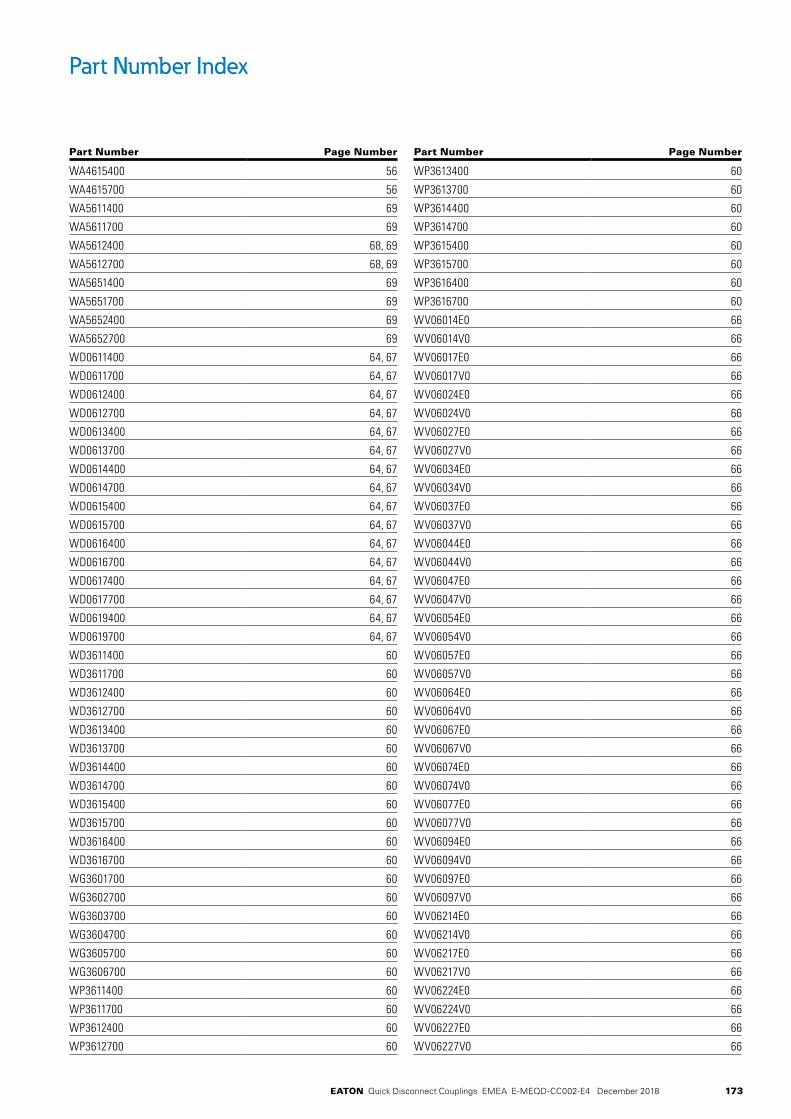
173EATON Quick Disconnect Couplings EMEA E-MEQD-CC002-E4 December 2018
Part Number Index
Part Number Page Number
WA4615400 56
WA4615700 56
WA5611400 69
WA5611700 69
WA5612400 68, 69
WA5612700 68, 69
WA5651400 69
WA5651700 69
WA5652400 69
WA5652700 69
WD0611400 64, 67
WD0611700 64, 67
WD0612400 64, 67
WD0612700 64, 67
WD0613400 64, 67
WD0613700 64, 67
WD0614400 64, 67
WD0614700 64, 67
WD0615400 64, 67
WD0615700 64, 67
WD0616400 64, 67
WD0616700 64, 67
WD0617400 64, 67
WD0617700 64, 67
WD0619400 64, 67
WD0619700 64, 67
WD3611400 60
WD3611700 60
WD3612400 60
WD3612700 60
WD3613400 60
WD3613700 60
WD3614400 60
WD3614700 60
WD3615400 60
WD3615700 60
WD3616400 60
WD3616700 60
WG3601700 60
WG3602700 60
WG3603700 60
WG3604700 60
WG3605700 60
WG3606700 60
WP3611400 60
WP3611700 60
WP3612400 60
WP3612700 60
Part Number Page Number
WP3613400 60
WP3613700 60
WP3614400 60
WP3614700 60
WP3615400 60
WP3615700 60
WP3616400 60
WP3616700 60
WV06014E0 66
WV06014V0 66
WV06017E0 66
WV06017V0 66
WV06024E0 66
WV06024V0 66
WV06027E0 66
WV06027V0 66
WV06034E0 66
WV06034V0 66
WV06037E0 66
WV06037V0 66
WV06044E0 66
WV06044V0 66
WV06047E0 66
WV06047V0 66
WV06054E0 66
WV06054V0 66
WV06057E0 66
WV06057V0 66
WV06064E0 66
WV06064V0 66
WV06067E0 66
WV06067V0 66
WV06074E0 66
WV06074V0 66
WV06077E0 66
WV06077V0 66
WV06094E0 66
WV06094V0 66
WV06097E0 66
WV06097V0 66
WV06214E0 66
WV06214V0 66
WV06217E0 66
WV06217V0 66
WV06224E0 66
WV06224V0 66
WV06227E0 66
WV06227V0 66
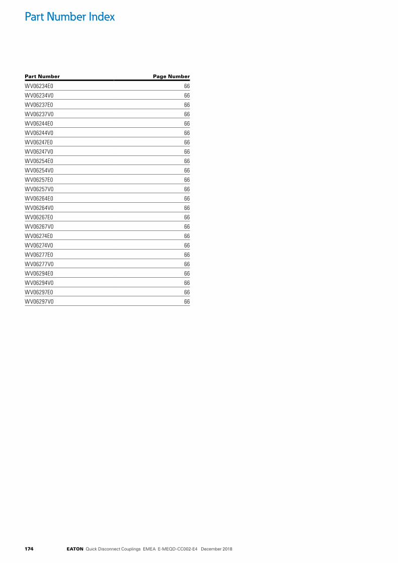
174 EATON Quick Disconnect Couplings EMEA E-MEQD-CC002-E4 December 2018
Part Number Index
Part Number Page Number
WV06234E0 66
WV06234V0 66
WV06237E0 66
WV06237V0 66
WV06244E0 66
WV06244V0 66
WV06247E0 66
WV06247V0 66
WV06254E0 66
WV06254V0 66
WV06257E0 66
WV06257V0 66
WV06264E0 66
WV06264V0 66
WV06267E0 66
WV06267V0 66
WV06274E0 66
WV06274V0 66
WV06277E0 66
WV06277V0 66
WV06294E0 66
WV06294V0 66
WV06297E0 66
WV06297V0 66

175EATON Quick Disconnect Couplings EMEA E-MEQD-CC002-E4 December 2018
Notes

© 2018 EatonAll Rights Reserved Printed in USADocument No. E-MEQD-CC002-E4December 2018
Eaton Hydraulics Group USA14615 Lone Oak RoadEden Prairie, MN 55344USATel: 952-937-9800Fax: 952-294-7722www.eaton.com/hydraulics
EatonHydraulics Group EuropeRoute de la Longeraie 71110 MorgesSwitzerlandTel: +41 (0) 21 811 4600Fax: +41 (0) 21 811 4601
Eaton Hydraulics Group Asia PacificEaton BuildingNo.7 Lane 280 Linhong Road Changning District, Shanghai 200335 ChinaTel: (+86 21) 5200 0099Fax: (+86 21) 2230 7240