easyPIC-40 User Manual
21
easyPIC-40 Development Board Users Manual www.LogiFind.com 1 To our valued customers I want to express my thanks to you for being interested in our products and for having confidence in LogiFind International CO.,Ltd. The primary aim of our company is to design and produce high quality electronic products and to constantly improve the performance thereof in order to better suit your needs. Please share your thoughts and feelings regarding our operation so that we can serve you better in the future. I thank you for your continued support and patronage. Your Dream is our Destination! The Microchip, TI,Freescale,ST,Atmel,Silicon and CYPRESS name, logo and products names are trade marks of Microchip, TI,Freescale,ST,Atmel,Silicon and CYPRESS Inc. in the U.S.A. and other countries. Sincerely, Owner and General Manager of LogiFind Tech CO., Ltd.
Transcript of easyPIC-40 User Manual

easyPIC-40 Development Board Users Manual
www.LogiFind.com 1
To our valued customers I want to express my thanks to you for being interested in our products and for having confidence in LogiFind International CO.,Ltd. The primary aim of our company is to design and produce high quality electronic products and to constantly improve the performance thereof in order to better suit your needs. Please share your thoughts and feelings regarding our operation so that we can serve you better in the future. I thank you for your continued support and patronage. Your Dream is our Destination! The Microchip, TI,Freescale,ST,Atmel,Silicon and CYPRESS name, logo and products names are trademarks of Microchip, TI,Freescale,ST,Atmel,Silicon and CYPRESS Inc. in the U.S.A. and other countries.
Sincerely,
Owner and General Manager of LogiFind Tech CO., Ltd.

easyPIC-40 Development Board Users Manual
www.LogiFind.com 2
CONTENTS Chapter 1: Introduction ....................................................................................................................................... 3
What’s easyPIC-40? ..................................................................................................................................... 3 What’s on Board? ......................................................................................................................................... 3 Power Supply ................................................................................................................................................. 4 Programmer/Debugger Requirement ...................................................................................................... 4 Devices Supported ....................................................................................................................................... 4
Chapter 2: Hardware Details .............................................................................................................................. 5 1.Power Supply and USB Connector ....................................................................................................... 5 2.DIP40 MCU Socket and Pinouts ............................................................................................................. 6 3.System Clock .............................................................................................................................................. 6 4.Six Digit 7-seg LED Display .................................................................................................................... 7 5.Eight LEDs ................................................................................................................................................... 7 6.4X4 Matrix Keypad ..................................................................................................................................... 8 7.Joystick ........................................................................................................................................................ 8 8.ULN2003A for Step Motor and Buzzer ................................................................................................. 9 9.DS18B20,Remote and ADC Modules .................................................................................................. 10 10.Real Time Clock and EEPROM Module ............................................................................................ 12 11.SD/MMC Card Module .......................................................................................................................... 14 12.UART via RS-232 ................................................................................................................................... 14 13.LCD 2x16 characters (Socket) ............................................................................................................ 15 14.GLCD 128x64(Socket) .......................................................................................................................... 17 15.ICSP Programming Port ...................................................................................................................... 18 16.System Reset ......................................................................................................................................... 19
Contact Us ............................................................................................................................................................ 20 DISCLAIMER ........................................................................................................................................................ 21 HIGH RISK ACTIVITIES ...................................................................................................................................... 21 TRADEMARKS ..................................................................................................................................................... 21

easyPIC-40 Development Board Users Manual
www.LogiFind.com 3
Chapter 1: Introduction
What’s easyPIC-40? The easyPIC-40 Development Board is a flexible and convenient development, demonstration and testing platform for Microchip's 8-bit PIC16F and PIC18F microcontrollers (MCUs) with 40 DIP packaging. It features lots of simple and basic modules to begin developing and learning a complete embedded application. All the modules on board are fully independent, which makes it easy and free to connect. The easyPIC-40 is an old friend. It has been with us for three generations. Many of us made our first steps in embedded world with easyPIC-40. Today it has thousands of users: students, hobbyists, enthusiasts and professionals. It is used in many schools and other educational institutions across the globe. We have sold them over 3000pcs in the world in the passed 3 years. It provides an low-cost easy-to-use platform with common modules to bring you into the colorful embedded world. Of course, we are not perfect and we asking ourselves what we can do to make such a board even better, and at the same time, we are looking forward to receiving your valuable suggestions.
What’s on Board?
Figure 1-1.What’s on board

easyPIC-40 Development Board Users Manual
www.LogiFind.com 4
Power Supply For connection with a power supply source the easyPIC-40 uses a Jack EX-PWR. The power supply voltage level can vary from +7-10V DC.
Programmer/Debugger Requirement An external PIC programmer or Debugger is required to download code to the DIP-40 PICs on the board.It supports many Programmers or Debuggers like PICKIT2,PICKIT3 or ICD2 etc.
Devices Supported The easyPIC-40 supports most 8bit DIP40 PICs,the following table shows the common devices.

easyPIC-40 Development Board Users Manual
www.LogiFind.com 5
Chapter 2: Hardware Details
1.Power Supply and USB Connector
单片机系统
(MC
U S
yste
m)
1 2 3
POWERSW
D1
PWR
12
3
VOUTVIN
GND
78M05
R2
1
2
POWER(7-10V)
J1
FUSE 5V3.3V
VCC
VCC
C7
104+C8
470uF
1234
USBPWR
12
3
VOUTVIN
GND
LM1117-3.3V
C4
104+C3
10uF
C6
104+C5
10uF
RC4RC5
Figure 2-1: Dual power supply unit schematic
easyPIC-40 Board contains power supply that creates stable voltage 5V and 3.3V and current levels necessary for powering each part of the board. Power supply section contains two power regulators: 78M05, which generates VCC-5V, and LM1117-3.3 which creates VCC-3.3V power supply. The board can be powered in two different ways: with USB power supply (USB/POWER), or using external adapters via adapter connector Jack (POWER(7-10V)). External adapter voltage levels must be in range of 7-10V DC. Use J1 to specify whether you are using 5V or 3.3V power supply for the system. Upon providing the power using either external adapter or USB power source you can turn on power supply by using POWERSW (Figure 2-1). Power LED (PWR) will indicate the presence of power supply.
12
USB-EN C27
106
RC3
单片机系统
(MC
U S
yste
m)
Figure 2-2: USB enable Jumper
The D- and D+ lines on USB power supply connector (USB/POWER) are connected to the Microcontroller socket, which are for creating a USB HID application if you are using a microcontroller

easyPIC-40 Development Board Users Manual
www.LogiFind.com 6
with USB module inside like PIC18F4550. The USB enable Jumper(Figure 2-2) is used to enable the USB function.
2.DIP40 MCU Socket and Pinouts The board contains a DIP40 socket which supports over 50 microcontrollers from PIC16F, PIC16LF, PIC18F and PIC18LF families. The easyPIC-40 development system comes with the PIC16F877A microcontroller in a DIP40 package by default.
123456789
1011121314151617181920 21
22232425262728293031323334353637383940
PIC-DIP40
MCLRRA0RA1RA2RA3RA4RA5RE0RE1RE2VCC
VCC
GND
GND
OSC1OSC2RC0RC1RC2RC3 RC4
RC5RC6RC7
RD0RD1 RD2
RD3
RD4RD5RD6RD7
RB0RB1RB2RB3RB4RB5RB6RB7
10
23
12345678
PORT-A
54
63
RA0RA1RA2RA3RA4RA5
12345678
PORT-B
12345678
PORT-C
12345678
PORT-D
RB0RB1RB2RB3RB4RB5RB6RB7
RC0RC1RC2RC3RC4RC5RC6RC7
RD0RD1RD2RD3RD4RD5RD6RD7
123
PORT-ERE0RE1RE2 VCC
C17104
VCC
C18104
VCCVCC
单片机系统
(MC
U S
yste
m)
Figure 2-3: DIP40 MCU Socket and Pinouts
3.System Clock The board contains a socket(Y1) which allow you to change the different crystal very easily.
Y1
C15 22PF
C16 22PF
OSC1
OSC2单片机系统(MCU Syst em)
Figure 2-4: System Clock

easyPIC-40 Development Board Users Manual
www.LogiFind.com 7
4.Six Digit 7-seg LED Display One seven segment digit consist of 7+1 LEDs which are arranged in a specific formation which can be used to represent digits from 0 to 9 and even some letters. One additional LED is used for marking the decimal dot, in case you want to write a decimal point in the desired segment. The easyPIC-40 contains six of these digits put together to form 6-digit 7-segment display. Driving such a display is done using multiplexing techniques. Data lines are shared between segments, and therefore the same segment LEDs in each digit are connected in parallel. Each digit has it’s unique digit select line, which is used to enable the digit to which the data is currently being sent. By multiplexing data through all six segments fast enough, you create an illusion that all six segments are in operation simultaneously. This is possible because human eye has a slower reaction time than the mention changes. This way you can represent numbers in decimal or hexadecimal form. Eight data lines that are common for all the digits are connected to connector (CN5), and digit select lines are connected to connector (CN6). The two connectors does not be connected to any IOs by default, and it makes your experiments more flexible. In order to enable Six Digit 7-seg Display Module, it is necessary to connected it to the appropriate IOs Port via connector (CN5) and (CN6) using dupont wires.
VOUTVIN
GND
13 12 6 5 4 14 11 7
1 2 3 10 9 8
a b c d e f g dp
D IG1 D IG2 DIG3 DIG4 D IG5 D IG6
7-SEGMENT
VCC
Q1Q2Q3Q4Q5Q6
VCCVCCVCCVCCVCC
R41R42R43R44R45R46
a b c d e f g dp
12345678
CN5
10
23
54
67
12345678
CN6
10
23
54
67
R33R34R35R36R37R38R39R40 dp
abcdefg
DIG1DIG2DIG3DIG4
DIG5DIG6
DIG1DIG2DIG3DIG4DIG5DIG6
Figure 2-5: Six Digit 7-seg Display Module
5.Eight LEDs LED (Light-Emitting Diode) is a highly efficient electronic light source. When connecting LEDs, it is necessary to place a current limiting resistor in series so that LEDs are provided with the current value specified by the manufacturer. The current varies from 0.2mA to 20mA, depending on the type of the LED and the manufacturer. The easyPIC-40 board uses low-current LEDs with typical current consumption of 0.2mA or 0.3mA, depending of VCC voltage selection. Board contains 8 LEDs which can be used for visual indication of the logic state on PORT pins. An active LED indicates that a logic high (1) is present on the pin.

easyPIC-40 Development Board Users Manual
www.LogiFind.com 8
The CN1 connector does not be connected to any IOs by default, and it makes your experiments more flexible. In order to enable LEDs, it is necessary to connected them to the appropriate IOs Port via connector (CN1) using dupont wires.
Figure 2-6: LEDs
6.4X4 Matrix Keypad 4X4 Matrix Keypad is used for loading numerics into the microcontroller. It consists of 16 buttons arranged in a form of an array containig four Rows and four columns. The CN3 connector does not be connected to any IOs by default, and it makes your experiments more flexible. In order to enable the 4X4 Matrix Keypad, it is necessary to connected it to the appropriate IOs Port via connector (CN3) using dupont wires.
VCC
1 2
3 4
KEY2
1 2
3 4
KEY1
1 2
3 4
KEY3
12345678
CN3
1 2
3 4
KEY4
1 2
3 4
KEY6
1 2
3 4
KEY5
1 2
3 4
KEY7
1 2
3 4
KEY8
1 2
3 4
KEY10
1 2
3 4
KEY9
1 2
3 4
KEY11
1 2
3 4
KEY12
1 2
3 4
KEY14
1 2
3 4
KEY13
1 2
3 4
KEY15
1 2
3 4
KEY16
R22R23R24R25
R29R28R27R26
Figure 2-7: 4X4 Matrix Keypad
7.Joystick Joystick is a smart navigation key concept based on contactless, magnetic movement detection. You can think it simply as 5 Tact Switchs installed on one device, and they are the Left, Right, Up, Down and Center. The easyPIC-40 contains a 5-Direction Jostick.
L1 L2 L3 L4 L5 L6 L7 L8
R7
R8
R9
R10
R11
R12
R13
R14
1 2 3 4 5 6 7 8
CN1

easyPIC-40 Development Board Users Manual
www.LogiFind.com 9
The CN2 connector does not be connected to any IOs by default, and it makes your experiments more flexible.In order to enable the Joystick, it is necessary to connected it to the appropriate IOs Port via connector (CN2) using dupont wires.
UP
CE NTE R
LEFT D OWN
RIG H TJoystick
VCC
12345678
CN2
10
23
54
67
R21R20R19R18R17
RIGHT
DOWN
LEFTUP
CENTER
RIGHT
DOWN
LEFTUP
CENTER
Figure 2-8: Joystick
8.ULN2003A for Step Motor and Buzzer The ULN2003A is high-voltage high-current Darlington transistor arrays. Each consists of seven npn Darlington pairs that feature high-voltage outputs with common-cathode clamp diodes for switching inductive loads. The collector-current rating of a single Darlington pair is 500 mA. The Darlington pairs can be paralleled for higher current capability. Applications include relay drivers, hammer drivers, lamp drivers, display drivers (LED and gas discharge), line drivers, and logic buffers. We use the ULN2003A to drive a Buzzer and a Stepper Motor (Figure 2-9).
VCC
VCC
1234 13
141516
5678 9
101112
IN1
IN3IN4
IN2OUT3OUT4
OUT2OUT1
IN5
IN7GND
IN6OUT7VCC
OUT6OUT5
ULN2003A
VCC
C24104
5V
32
54
1
VCCABCD
STEPMOTOR
10
23
12345678
CN4
54
63
+
BUZZER/SPEAKER
Figure 2-9: ULN2003A Drive Module for Step Motor and Buzzer

easyPIC-40 Development Board Users Manual
www.LogiFind.com 10
Figure 2-10: BYJ-48-5V Step Motor
The CN4 connector does not be connected to any IOs by default, and it makes your experiments more flexible.In order to enable the ULN2003A Drive Module to drive the stepmotor, it is necessary to connected it to the appropriate IOs Port via connector (CN4) using dupont wires.
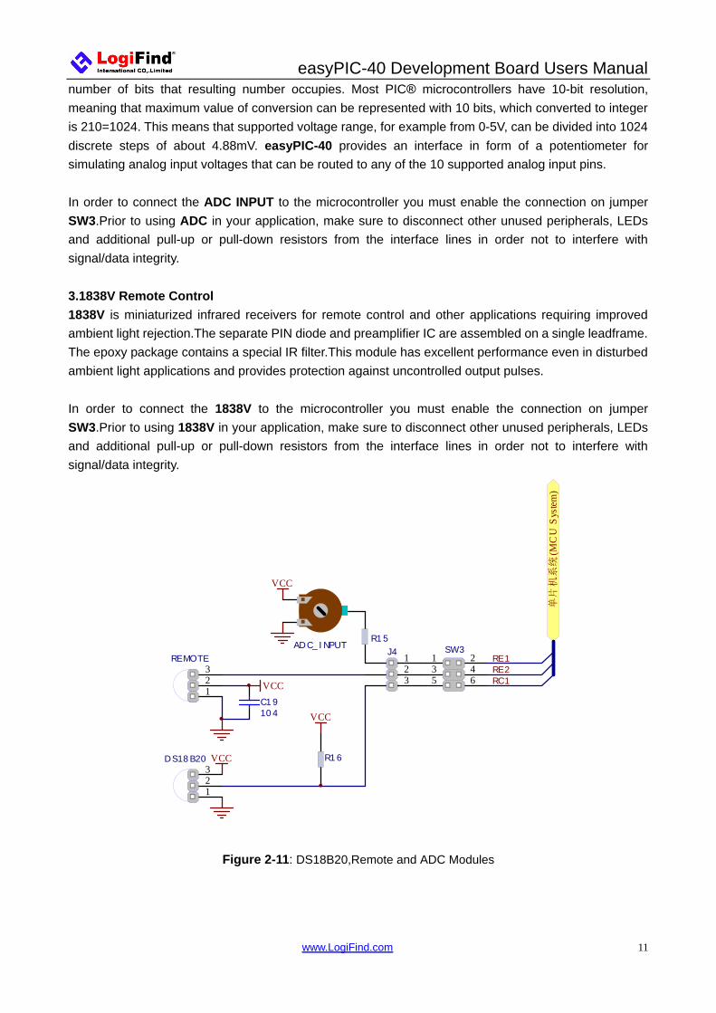
9.DS18B20,Remote and ADC Modules 1.DS18B20 - Digital Temperature Sensor DS18B20 is a digital temperature sensor that uses 1-wire® interface for it’s operation. It is capable of measuring temperatures within the range of -55 to 128°C, and provides ±0.5°C accuracy for temperatures within the range of -10 to 85°C. It requires 3V to 5.5V power supply for stable operation. It takes maximum of 750ms for the DS18B20 to calculate temperature with 9-bit resolution. 1-wire® serial communication enables data to be transferred over a single communication line, while the process itself is under the control of the master microcontroller. The advantage of such communication is that only one microcontroller pin is used. Multiple sensors can be connected on the same line. All slave devices by default have a unique ID code, which enables the master device to easily identify all devices sharing the same interface.The easyPIC-40 provides a separate socket for the DS18B20. Communication line with the microcontroller is connected via jumper SW3.3. In order to connect the DS18B20 to the microcontroller you must enable the connection on jumper SW3.Prior to using DS18B20 in your application,make sure to disconnect other unused peripherals, LEDs and additional pull-up or pull-down resistors from the interface lines in order not to interfere with signal/data integrity. 2.ADC input Digital signals have two discrete states, which are decoded as high and low, and interpreted as logic 1 and logic 0. Analog signals, on the other hand, are continuous, and can have any value within defined range. A/D converters are specialized circuits which can convert analog signals (voltages) into a digital representation, usually in form of an integer number. The value of this number is linearly dependent on the input voltage value. Most microcontrollers nowadays internally have A/D converters connected to one or more input pins. Some of the most important parameters of A/D converters are conversion time and resolution. Conversion time determines how fast can an analog voltage be represented in form of a digital number. This is an important parameter if you need fast data acquisition. The other parameter is resolution. Resolution represents the number of discrete steps that supported voltage range can be divided into. It determines the sensitivity of the A/D converter. Resolution is represented in maximum
easyPIC-40 Development Board Users Manual
www.LogiFind.com 11
number of bits that resulting number occupies. Most PIC® microcontrollers have 10-bit resolution, meaning that maximum value of conversion can be represented with 10 bits, which converted to integer is 210=1024. This means that supported voltage range, for example from 0-5V, can be divided into 1024 discrete steps of about 4.88mV. easyPIC-40 provides an interface in form of a potentiometer for simulating analog input voltages that can be routed to any of the 10 supported analog input pins. In order to connect the ADC INPUT to the microcontroller you must enable the connection on jumper SW3.Prior to using ADC in your application, make sure to disconnect other unused peripherals, LEDs and additional pull-up or pull-down resistors from the interface lines in order not to interfere with signal/data integrity. 3.1838V Remote Control 1838V is miniaturized infrared receivers for remote control and other applications requiring improved ambient light rejection.The separate PIN diode and preamplifier IC are assembled on a single leadframe. The epoxy package contains a special IR filter.This module has excellent performance even in disturbed ambient light applications and provides protection against uncontrolled output pulses. In order to connect the 1838V to the microcontroller you must enable the connection on jumper SW3.Prior to using 1838V in your application, make sure to disconnect other unused peripherals, LEDs and additional pull-up or pull-down resistors from the interface lines in order not to interfere with signal/data integrity.
VCC
VCC
VCC
VCC
RE1
RC1
C19104
RE2321
REMOTE
321
DS18B20
ADC_INPUT123
J4 1 23 45 6
SW3R15
R16
单片机系统
(MC
U S
yste
m)
Figure 2-11: DS18B20,Remote and ADC Modules

easyPIC-40 Development Board Users Manual
www.LogiFind.com 12
10.Real Time Clock and EEPROM Module 1.EEPROM EEPROM is short for Electrically Erasable Programmable Read Only Memory. It is usually a secondary storage memory in devices containing data that is retained even if the device looses power supply. Because of the ability to alter single bytes of data, EEPROM devices are used to store personal preference and configuration data in a wide spectrum of consumer, automotive, telecommunication, medical, industrial, and PC applications. The easyPIC-40 supports serial EEPROM which uses I2C communication interface and has 1024 bytes of available memory. Board contains socket for serial EEPROMs in DIP8 packaging, so you can easily exchange it with different memory size EEPROM IC. EEPROM itself supports single byte or 16-byte (page) write and read operations. Data rate is 400 kHz for both 3.3V and 5V power supply. I2C is a multi-master serial single-ended bus that is used to attach low-speed peripherals to computer or embedded systems. I²C uses only two open-drain lines, Serial Data Line (SDA) and Serial Clock (SCL), pulled resistors. SCL line is driven by a master, while SDA is used as bidirectional line either by master or slave Up to 112 slave devices can be connected to the same bus. Each slave must have a unique address.
1234 5
678
VCC2
X2VSS
X1
RSTIO
SLCKVCC1
DS1302
1234 5
678
A0
A2VSS
A1
SDASCLWP
VCC
24CXX
Y2
C22
104
C23
104 VCC
VCC
VCCVCC
C20104
VCC
C21104
12345
J5 1 23 45 67 89 10
SW4
RB0RB4RB5
RC3RC4
R30 R31
BT
单片机系统
(MC
U S
yste
m)
Figure 2-12: Real Time Clock and EEPROM Module
In order to connect I2C EEPROM to the microcontroller you must enable the connection on jumper SW4.Prior to using EEPROM in your application,make sure to disconnect other unused peripherals, LEDs and additional pull-up or pull-down resistors from the interface lines in order not to interfere with signal/data integrity. 2.DS1302 Real Time Clock The DS1302 Trickle Charge Timekeeping Chip contains a real time clock/calendar and 31 bytes of static RAM. It communicates with a microprocessor via a simple serial interface. The real time clock/calendar

easyPIC-40 Development Board Users Manual
www.LogiFind.com 13
provides seconds, minutes, hours, day, date, month, and year information. The end of the month date is automatically adjusted for months with less than 31 days, including corrections for leap year. The clock operates in either the 24–hour or 12–hour format with an AM/PM indicator. Interfacing the DS1302 with a microprocessor is simplified by using synchronous serial communication. Only three wires are required to communicate with the clock/RAM: (1) RST (Reset), (2) I/O (Data line), and (3) SCLK (Serial clock). Data can be transferred to and from the clock/RAM 1 byte at a time or in a burst of up to 31 bytes. The DS1302 is designed to operate on very low power and retain data and clock information on less than 1 microwatt. The DS1302 is the successor to the DS1202. In addition to the basic timekeeping functions of the DS1202, the DS1302 has the additional features of dual power pins for primary and back–up power supplies, programmable trickle charger for VCC1, and seven additional bytes of scratchpad memory.
Figure 2-13: DS1302 pin assignment
Num Name Function 1 VCC2 Power Supply Pins 2 X1, 32.768 kHz Crystal Pins 3 X2 32.768 kHz Crystal Pins 4 GND Ground 5 RST Reset 6 I/O Data Input/Output 7 SCLK Serial Clock 8 VCC1 Power Supply Pins
In order to connect DS1302 module to the microcontroller you must enable the connection on jumper SW4 .Prior to using DS1302 RTC in your application,make sure to disconnect other unused peripherals, and additional pull-up or pull-down resistors from the interface lines in order not to interfere with signal/data integrity.

easyPIC-40 Development Board Users Manual
www.LogiFind.com 14
11.SD/MMC Card Module 单片机系统
(MC
U S
yste
m)
3.3V
VCCC14
104
R3R4 R5 R6
3.3V
1234
J3CS1
Din2
3.3V4
SCK5
GND6
Dout7
NC8
DAT29
GND3
SD Card
1 23 45 67 8
SW2RC2
RC3RC4
RC5
Figure 2-14: SD/MMC Card Module A MultiMedia Card (MMC) is a memory card manufactured in Flash technology. The standard size of these cards is 24×32×1.4 mm. MMC cards have been superseded by Secure Digital Cards (SD cards) lately, but they are still very popular and widely used because they can be utilized with most devices that support SD cards. Both types of cards are used as memory data storage in portable devices such as cameras, digital audio players, cellular phones, etc. Most modern computers are supplied with an MMC/SD slot that can read both MMC and SD cards. The MMC/SD module enables data read/write between a microcontroller and MMC/SD cards. Data transfer is performed via a standard Serial Peripheral Interface (SPI). This module only 3.3V power supply. In order to connect SD/MMC Card Module to the microcontroller you must enable the connection on jumper SW2 . Prior to using The SD/MMC Card Module in your application, make sure to disconnect other unused peripherals, and additional pull-up or pull-down resistors from the interface lines in order not to interfere with signal/data integrity.
12.UART via RS-232 The UART (universal asynchronous receiver/transmitter) is one of the most common ways of exchanging data between the MCU and peripheral components. It is a serial protocol with separate transmit and receive lines, and can be used for full-duplex communication. Both sides must be initialized with the same baud rate, otherwise the data will not be received correctly. RS-232 serial communication is performed through a 9-pin SUB-D connector and the microcontroller UART module. In order to enable this communication, it is necessary to establish a connection between RX and TX

easyPIC-40 Development Board Users Manual
www.LogiFind.com 15
lines on SUB-D connector and the same pins on the target microcontroller using jumper SW1. Since RS-232 communication voltage levels are different than microcontroller logic levels, it is necessary to use a RS-232 Transceiver circuit, such as SP232 as shown on Figure 2-15.
单片机系统
(MC
U S
yste
m)1
2
3
4
5
6
7
8 9
10
11
12
13
14
15
16C1+
C1 -
C2 -
C2+
V+
V-
T2OUT
T1OUT
R2 IN
T2 IN
R2OUT
T1 IN
R1 IN
R1OUT
GND
VCC
RS232
1
2
3
4
5
6
7
8
9
UART
VCC
VCC
C10104
C11
104
C9
104
C12
104
VCC
C13104
12
J2 1 23 4
SW1 RC6RC7
Figure 2-15: RS232 Module
In order to connect RS232 Module to the microcontroller you enable the connection on jumper SW1. Prior to using The RS232 Module in your application, make sure to disconnect other unused peripherals, and additional pull-up or pull-down resistors from the interface lines in order not to interfere with signal/data integrity.
13.LCD 2x16 characters (Socket) Liquid Crystal Displays or LCDs are cheap and popular way of representing information to the end user of some electronic device. Character LCDs can be used to represent standard and custom characters in the predefined number of fields. The easyPIC-40 provides the connector and the necessary interface for supporting 2x16 character LCDs. This type of display has two rows consisted of 16 character fields. Each field is a 7x5 pixel matrix. Board equips an universal socket allowing you to install 16x2 LCD very easily. Connector pinout explained 1-GND 2-5V 3-Vo,LCD contrast level from potentiometer 1602-VOL 4-RS,Register Select Signal 5-E,Display Enable 6-R/W,Determines whether display is in Read or Write mode. It’s always connected to GND, leaving the display in Write mode all the time. 7~14-Data Port,Display is supported in 8-bit data mode. 15-LED+,Connection with 5V 16-LED-,Connection with GND

easyPIC-40 Development Board Users Manual
www.LogiFind.com 16
单片机系统
(MC
U S
yste
m)
5V1602-VOL
5V
5V
RA1RA2RA3RD0RD1RD2RD3RD4RD5RD6RD7 5V
C26104
12345678910111213141516
VSSVDDVORS
R/WE
D0D1D2D3D4D5D6D7
AK
LCD1602
Figure 2-16: LCD 2x16 characters Socket
IMPORTANT: Make sure to Place the LCD1602 in the right direction. Make sure to turn off the power supply before placing LCD onto the board. Otherwise your display can be permanently damaged.
Figure 2-17: LCD1602 Installing Direction

easyPIC-40 Development Board Users Manual
www.LogiFind.com 17
14.GLCD 128x64(Socket) Graphical Liquid Crystal Displays, or GLCDs are used to display monochromatic graphical content, such as text, images, humanmachine interfaces and other content. The easyPIC-40 provides the connector and necessary interface for supporting GLCD with resolution of 128x64 pixels and proper PINOUTs.It is compatible with the most popular LCD12864 in the market with KS108 or ST7920 display controller.The example we provide is only for LCD12864 with ST7920 display controller.The easyPIC-40 equips an universal socket allowing you to install 128*64 Graphical LCD very easily.
单片机系统(MCU Syst em)
5V
5V
5V
12864-VOL
RA0
RA1
RA2
RD0
RD1
RD2
RD3
RD4
RD5
RD6
RD7
RA3
RA4
1 2 3 4 5 6 7 8 9 10 11 12 13 14 15 16
VS
SVD
DVO RS
R/W E D0 D1 D2 D3 D4 D5 D6 D7 CS
1CS
217 18 19 20
RS
TVE
E A K
LCD12864 ` Figure 2-18: LCD12864 characters Socket
Connector pinout explained: 1-GND 2-VCC 3-Vo,GLCD contrast level from potentiometer 12864-VOL 4-RS,Data (High), Instruction (Low) selection 5-R/W,Determines whether display is in Read or Write mode. 6-E,Display Enable line 7~14,D0–D7,Data lines 15-PSB,Parallel/Serial Mode Selection 16-NC 17-RST 18-VEE 19-LEDA - 5V 20-LEDK – GND

easyPIC-40 Development Board Users Manual
www.LogiFind.com 18
Figure 2-19: LCD12864 Installing Direction IMPORTANT: Make sure to Place the LCD12864 in the right direction. Make sure to turn off the power supply before placing LCD onto the board. Otherwise your display can be permanently damaged.
15.ICSP Programming Port In-Circuit Serial Programming (ICSP) is an enhanced ISP technique implemented in Microchip’s PICmicro One-Time-Programmable (OTP) and FLASH RISC microcontrollers (MCU). Use of only two I/O pins to serially input and output data makes ICSP easy to use and less intrusive on the normal operation of the MCU.
VCC 123456
ICSP1
NCPG CPG DG NDVCCVP P/MCLR1
23456
ICSP2
VCC
RB6RB7
MCLR
单片机系统
(MC
U S
yste
m)
Figure 2-20: ICSP Connector

easyPIC-40 Development Board Users Manual
www.LogiFind.com 19
The easyPIC-40 has two standard ICSP interfaces (ICSP1 and ICSP2) which allow you to connect PICKIT2, PICKIT3, ICD2 or other Third-party Programmer/debugger directly.
16.System Reset The easyPIC-40 reset circuit is made with 10K pull-up resistor, RESET button connected to GND and a 0.1uF capacitor for filtering.
单片机系统
(MC
U S
yste
m)
C25
104
VCC
1 2
3 4
RESET
MCLRR32
Figure 2-21: System Reset

easyPIC-40 Development Board Users Manual
www.LogiFind.com 20
Contact Us
Nanning LogiFind Tech CO.,LTD
Room 2409,B# of Nanguo Building,NO.16,Zhuxi South Road,Nanning,Guangxi,P.R.China
Mobile:(0086)15978193886/TEL: (0086)0771-5677749
Skype:love100mhz
E-MAIL:[email protected]
Website:www.LogiFind.com
www.MicroHello.com
If you want to learn more about our products, please visit our website at:
www.LogiFind.com or www.MicroHello.com
If you have any questions, comments or business proposals, contact us at:

easyPIC-40 Development Board Users Manual
www.LogiFind.com 21
DISCLAIMER All the products owned by LogiFind are protected by copyright law and international copyright treaty. Therefore, this
manual is to be treated as any other copyright material. No part of this manual, including product and software described
herein, must be reproduced, stored in a retrieval system, translated or transmitted in any form or by any means, without
the prior written permission of LogiFind. The manual PDF edition can be printed for private or local use, but not for
distribution. Any modification of this manual is prohibited.
LogiFind provides this manual ‘as is’ without warranty of any kind, either expressed or implied, including, but not limited
to, the implied warranties or conditions of merchantability or fitness for a particular purpose.
LogiFind shall assume no responsibility or liability for any errors, omissions and inaccuracies that may appear in this
manual. In no event shall LogiFind, its directors, officers, employees or distributors be liable for any indirect, specific,
incidental or consequential damages (including damages for loss of business profits and business information, business
interruption or any other pecuniary loss) arising out of the use of this manual or product, even if LogiFind has been
advised of the possibility of such damages. LogiFind reserves the right to change information contained in this manual at
any time without prior notice, if necessary.
HIGH RISK ACTIVITIES The products of LogiFind are not fault – tolerant nor designed, manufactured or intended for use or resale as on – line
control equipment in hazardous environments requiring fail – safe performance, such as in the operation of nuclear
facilities, aircraft navigation or communication systems, air traffic control, direct life support machines or weapons systems
in which the failure of Software could lead directly to death, personal injury or severe physical or environmental damage
(‘High Risk Activities’). LogiFind and its suppliers specifically disclaim any expressed or implied warranty of fitness for
High Risk Activities.
TRADEMARKS The LogiFind name and logo are trademarks of LogiFind. All other trademarks mentioned herein are property of their
respective companies.All other product and corporate names appearing in this manual may or may not be registered
trademarks or copyrights of their respective companies, and are only used for identification or explanation and to the
owners’ benefit, with no intent to infringe.
Copyright © LogiFind, 2019, All Rights Reserved.