EASA Operational Suitability Data (OSD) Flight Crew … Report... · EASA Operational Suitability...
28
EASA Operational Suitability Data (OSD) Flight Crew Data EC 175B 31 10 2014 Jean-Marc SACAZES Deputy Head of Rotorcraft Department Certification Directorate- EASA European Aviation Safety Agency (EASA), Postfach 10 12 53 D-50452 Köln, Germany
Transcript of EASA Operational Suitability Data (OSD) Flight Crew … Report... · EASA Operational Suitability...

EASA Operational Suitability Data (OSD) Flight Crew Data
EC 175B 31 10 2014
Jean-Marc SACAZES Deputy Head of Rotorcraft Department
Certification Directorate- EASA
European Aviation Safety Agency (EASA), Postfach 10 12 53 D-50452 Köln, Germany

3
Revision Record
Revision No. Content Pages N° Date
OSD FC Original EC175-B Initial Evaluation
31/10/2014

4
Contents
EASA Operational Suitability Data (OSD) ........... ...................................... …………….2
Revision Record ................................... ...................................................... …………….3
Preamble/ General ................................. .......................................................................... 8
1. Introduction ................................... ............................................................................... 8
2. Operational Evaluations – Group Composition .... .................................................... 8
3. Airbus Helicopters Specialists Subgroup involved in the process ......................... 8
4. Purpose and applicability ...................... ..................................................................... 8
Subpart A / General ............................... .......................................................................... 9
Aircraft Specifics ................................ ......................................................................... 9
General ........................................... .............................................................................. 9
Main Rotor ........................................ ............................................................................ 9
Tail Rotor ........................................ .............................................................................. 9
Flight controls.................................... .......................................................................... 10
Drive System ...................................... .......................................................................... 10
Engines ........................................... ............................................................................. 10
Fuel system ....................................... ........................................................................... 10
Avionic ........................................... .............................................................................. 11
Automatic Flight Control System ................... ............................................................ 11
Hydraulic system .................................. ....................................................................... 11
Electric system ................................... ......................................................................... 11
Subpart B / Minimum Traning Syllabus Requirement .. ................................................ 12
1. Applicability ..................................... ...................................................................... 12
4. Type rating courses [M] ........................... ............................................................. 12
5. Training Areas of Specific Emphasis [M]. .......... ................................................. 15

5
Subpart C / Recommendations for training and operat ions ........................................ 18
Acceptable Means of Compliance [AMC] .............. ........................................................ 18
1. Applicability ..................................... ...................................................................... 18
2. Special Events Training ........................... ............................................................. 18
3. Multi Engine Consolidation ........................ .......................................................... 18
4. Transition to Digital Cockpit ..................... ........................................................... 18
5. Specific Trainings ................................ ................................................................. 19
6. Training Means .................................... .................................................................. 20
7. Recurrent Training ................................ ................................................................ 21
8. Recurrent Checking (OPC and LPC) .................. ................................................. 22
9. Recent experience ................................. ............................................................... 22
10. Line flying under supervision (LIFUS) / Supervised Operating Experience (SOE) ...................................................................................................................... 22
Appendix 1 – EC175 HMI concepts ................... ............................................................. 23
1. Fly the rotorcraft ................................ ................................................................... 23
2. Managing systems of the rotorcraft ................ .................................................... 26

6
Acronyms
ATO .............................. Approved Training Organisation
CAS ............................. Crew Alerting System
CBT ............................. Computer Based Training
CCP .............................. Crew Coordination Procedure
CPD .............................. Common Procedures Document for conducting Operational Evaluation Boards, dated 10 June 2004
CS-FCD ....................... Certification Specifications for Operational Suitability Data (OSD) Flight Crew Data CS-FCD, Initial issue, 31 January 2014
CS-FSTD(H) ................ Certification Specifications for Helicopter Flight Simulation Training Devices of 4 July 2012
Difference Level ........... a designated level of difference as defined in CS-FCD for the evaluation of pilot training, checking and currency
DU ................................ Display Unit
EASA ............................ European Aviation Safety Agency
ECL ............................. Electronic Checklist
EFB .............................. Electronic Flight Bag
EFIS ............................. Electronic Flight Instrument System
EGPWS ........................ Enhanced Ground Proximity Warning System
EICAS........................... Engine Indicating and Crew Alerting System
EU-OPS ....................... Commission Regulation (EC) No 859/2008 of 20 August 2008, amending Council Regulation (EEC) No 3922/91 as regard common technical requirements and administrative procedures applicable to commercial transportation by aeroplane
FAA .............................. Federal Aviation Administration
FCL ............................... Flight Crew Licensing
FD ................................. Flight Director
FFS ............................... Full Flight Simulator
FMS .............................. Flight Management System
FSB .............................. Flight Standardization Board
FSTD ........................... Flight Simulation Training Device
FT ................................. Flight Time
GPWS .......................... Ground Proximity Warning System
IPT ............................... Instrument Procedure Trainer
IR ................................. Instrument Rating
JAA ............................... Joint Aviation Authorities
LIFUS ........................... Line Flying Under Supervision
LPC ............................. License Proficiency Check
MDR ............................ Master Differences Requirements
ME ................................ Multi-Engine
MFD.............................. Multi-Function Display
MP ................................ Multi-Pilote
MPA.............................. Multi-Pilot Aeroplane
NAA .............................. National Aviation Authority
ODR ............................ Operator Differences Requirements
OEB .............................. Operational Evaluation Board
OPC ............................. Operator Proficiency Check
OSD ............................. Operational Suitability Data
OTD ............................. Other Training Device

7
Part-ARA ...................... Annex VI to Commission Regulation (EU) No 290/2012 of 30 March 2012 amending Regulation (EU) No 1178/2011 laying down technical requirements and administrative procedures related to civil aviation aircrew pursuant to Regulation (EC) No 216/2008 of the European Parliament and of the Council (as amended)
Part-ARO ...................... Annex II to Commission Regulation (EU) No 965/2012 of 05 Oct 2012 laying down technical requirements and administrative procedures related to air operations pursuant to Regulation (EC) No 216/2008 of the European Parliament and of the Council (as amended)
Part-CAT ...................... Annex IV to Commission Regulation (EU) No 965/2012 of 05 Oct 2012 laying down technical requirements and administrative procedures related to air operations pursuant to Regulation (EC) No 216/2008 of the European Parliament and of the Council (as amended)
Part-FCL ....................... Annex I to Commission Regulation (EU) No 1178/2011 of 3 November 2011 laying down technical requirements and administrative procedures related to civil aviation aircrew pursuant to Regulation (EC) No 216/2008 of the European Parliament and of the Council (as amended)
Part-ORA ...................... Annex VII to Commission Regulation (EU) No 290/2012 of 30 March 2012 amending Regulation (EU) No 1178/2011 laying down technical requirements and administrative procedures related to civil aviation aircrew pursuant to Regulation (EC) No 216/2008 of the European Parliament and of the Council (as amended)
Part-ORO ..................... Annex III to Commission Regulation (EU) No 965/2012 of 05 Oct 2012 laying down technical requirements and administrative procedures related to air operations pursuant to Regulation (EC) No 216/2008 of the European Parliament and of the Council (as amended)
Part-SPA ...................... Annex V to Commission Regulation (EU) No 965/2012 of 05 Oct 2012 laying down technical requirements and administrative procedures related to air operations pursuant to Regulation (EC) No 216/2008 of the European Parliament and of the Council (as amended)
PF/PM .......................... Pilot Flying/Pilot Monitoring
PFD .............................. Primary Flight Display
PIC ............................... Pilot In Command
Route Sector ............... as defined in Part-FCL [“Route sector" means a flight comprising take-off, departure, cruise of not less than 15 minutes, arrival, approach and landing phases]
SOE .............................. Supervised Operating Experience
SOP .............................. Standard Operating Procedure
TASE ............................ Training Areas of Special Emphasis
TAWS ........................... Terrain Awareness and Warning System
TCAS ............................ Traffic Alert and Collision Avoidance System VFR ............................ Visual Flight Rules

8
Preamble
1. Introduction
Where references are made to requirements and where extracts of reference texts are provided, these are at the amendment state at the date of evaluation or publication of this document. Users should take account of subsequent amendments to any references, in particular concerning requirement for civil aviation aircrew and air operations.
Determinations made in this document are based on the evaluations of specific configurations of aircraft models, equipped in a given configuration and in accordance with current regulations and guidance.
Modifications and upgrades to the aircraft evaluated require additional OSD assessment for type designation, training / checking / currency, operational credits, and other elements within the scope of the OSD evaluations.
In accordance with Commission Regulation (EU) No 69/2014 of 27 Jan 2014, the Operational Suitability Data contained in this document are identified as follows: [M]…….Mandatory Operational Suitability Data, bearing the status of rule (see GM No 3 to 21A.15(d)) [AMC] …Non-mandatory Operational Suitability Data, bearing the status of Acceptable Means of Compliance
(see GM No 3 to 21A.15(d)) 2. Operational Evaluations – Group Composition
Name Organization Function
Alexandre ANTUNES DGAC / France-DSAC/PN/Pôle Expertises du Personnel Navigant Team Member
Jean-Marc SACAZES EASA Chairman –
HoD of Rotorcraft Department
3. Airbus Helicopters Specialists Subgroup involved in the process
4. Purpose and applicability Data is being submitted by Airbus Helicopters in support of the EC175 helicopter certification process. This document: Provides a general description of the EC175 Updates the Type Rating List by including the EC175 helicopter type Makes recommendations for minimum training syllabus for type rating Gives specification for Training Areas of Specific Emphasis (TASE).
Name Position Office / Branch
Alain Di Bianca Experimental Test Pilot Airbus Helicopters France - ETXPF
Laurent Vautherin Vice President Training Simulation and Customer Flight Operations Department
Jérôme Combe Head of Product Policy Marketing Department - EBMX
Christophe Meny Experimental Test Pilot Airbus Helicopters France - ETXPF
Christophe Marchal Head of Pilot Training Airbus Helicopters Training Services - E.ETS-V
William Pasquon Chief Flight Instructor Airbus Helicopters Training Services - E.ETS-V
Luc Nouvel TheoreticalTraining Instructor Airbus Helicopters Training Services - E.ETS-V
Bruno Plaquin TheoreticalTraining Instructor Airbus Helicopters Training Services -E.ETS-V
Martin Burnand Training & Simulation Expert Airbus Helicopters France - EBSTS
François-Xavier de BENGY
Training & Simulation Expert Airbus Helicopters France - EBSTS
Stéphanie PEREIRA EC175 Certif/Qualification Airbus Helicopters France - ETIC

9
Subpart A
General
Aircraft Specifics
EC175-B was evaluated in accordance with CS-FCD and the relevant requirements for pilot licensing and air operations which were applicable at the time of the evaluation. AIRBUS HELICOPTERS Manufacturer produces the EC175 in a single variant “EC175-B”.This helicopter is a twin Turbine Engine Helicopter approved as Large Rotorcraft under CS-29, Category A and category B.
General
The EC175 is a 7 tons class multi-mission helicopter, approved for VFR and IFR operations, day and night, in non-icing conditions. Minimum crew is: • two pilots, • one pilot for VFR flights (refer to Rotorcraft Flight Manual).
Passengers: EC175-B can accommodate up to 18 passengers (excluding flight crew).
Main Rotor
The main rotor system is a five bladed type rotor rotating clockwise (as seen from above). Each glass/carbon-fibre blade is fitted on a SPHERIFLEX® rotor head with lower and upper gust and droop stops. The hub is dissociated from the mast in order to allow disassembling the swash-plates without having to remove the mast and the upper housing.
Tail Rotor
The tail rotor is a three bladed type rotor located on the left side of the aircraft. It is composed of three glass / carbon-fibre blades. It has also one SPHERIFLEX® rotor head fitted with flapping stops on a tail rotor mast-hub. The integrated mast-hub belongs to the TGB assembly.

10
Flight controls
The EC175-B flight controls consist in one mechanical/hydraulic flight control system in a side-by-side configuration. Controls are totally separated between the main rotor and the tail rotor: • Main rotor control is fitted with three fixed tandem body main servo-units (on cyclic and collective pitch channels). • Tail rotor control is fitted with one fixed tandem body rear servo-unit (on tail rotor pitch control channel).
Drive System
One main gearbox (MGB) with oil level sight, a filler plug with breather device, oil pressure and temperature sensors, and six chip detectors. The main gearbox accessories stage includes two accessory gearboxes for power transmission to accessories. • One rotor brake system. • One lubrication system with one main oil pump and one emergency oil
pump. • One main gearbox oil cooling system consisting in a cooling fan, a heat
exchanger and oil pipes. • MGB suspension system so that the bottom of the MGB is directly linked to the suspension (MGB
isolating system).
The tail drive system is composed of the following elements: • One tail rotor drive line to transmit the power from tail rotor output flange to the tail rotor gearbox via the
intermediate gearbox • One splash lubricated intermediate gearbox. • One splash lubricated tail gearbox.
Engines
The EC175 is powered by two Pratt & Whitney PT6C-67E engines installed in parallel to each other in two engine compartments. They are controlled via a Full Authority Digital Engine Control (FADEC) system . The PT6C-67E is a free turbine turbo shaft engine with an output shaft speed of 21000 rpm. It is made of: One gas generator - 4 Axial compressor stages, One centrifugal compressor stage, One Combustion chamber with reverse flow, One Single Crystal compressor turbine stage (with blade melting concept), Two Power turbine stages (with blade shedding protection) linked to output shaft power in connection
with H/C Main Gear Box. The unusual AEO HIP/SARM rating allows the rotorcraft to fly extended hover manoeuvres while performing search and rescue missions. It corresponds to the same power level than TOP and is limited to a 30 minutes continuous usage.
Fuel system
The fuel system is crashworthy and includes storage, distribution and indicating system. The fuel tank installation has five tanks with a total usable capacity of 2,533 litres (669 US gal). They are refuelled via a single port gravity fuel filler or a ground pressure refuelling equipment that increases usable capacity to 2,616 litres (691 US gal).
11
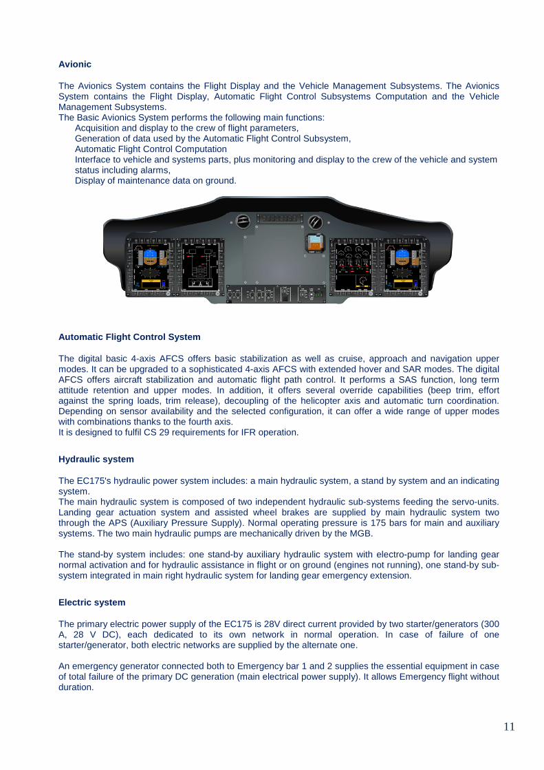
Avionic
The Avionics System contains the Flight Display and the Vehicle Management Subsystems. The Avionics System contains the Flight Display, Automatic Flight Control Subsystems Computation and the Vehicle Management Subsystems. The Basic Avionics System performs the following main functions:
Acquisition and display to the crew of flight parameters, Generation of data used by the Automatic Flight Control Subsystem, Automatic Flight Control Computation Interface to vehicle and systems parts, plus monitoring and display to the crew of the vehicle and system status including alarms, Display of maintenance data on ground.
Automatic Flight Control System
The digital basic 4-axis AFCS offers basic stabilization as well as cruise, approach and navigation upper modes. It can be upgraded to a sophisticated 4-axis AFCS with extended hover and SAR modes. The digital AFCS offers aircraft stabilization and automatic flight path control. It performs a SAS function, long term attitude retention and upper modes. In addition, it offers several override capabilities (beep trim, effort against the spring loads, trim release), decoupling of the helicopter axis and automatic turn coordination. Depending on sensor availability and the selected configuration, it can offer a wide range of upper modes with combinations thanks to the fourth axis. It is designed to fulfil CS 29 requirements for IFR operation.
Hydraulic system
The EC175's hydraulic power system includes: a main hydraulic system, a stand by system and an indicating system. The main hydraulic system is composed of two independent hydraulic sub-systems feeding the servo-units. Landing gear actuation system and assisted wheel brakes are supplied by main hydraulic system two through the APS (Auxiliary Pressure Supply). Normal operating pressure is 175 bars for main and auxiliary systems. The two main hydraulic pumps are mechanically driven by the MGB. The stand-by system includes: one stand-by auxiliary hydraulic system with electro-pump for landing gear normal activation and for hydraulic assistance in flight or on ground (engines not running), one stand-by sub-system integrated in main right hydraulic system for landing gear emergency extension.
Electric system
The primary electric power supply of the EC175 is 28V direct current provided by two starter/generators (300 A, 28 V DC), each dedicated to its own network in normal operation. In case of failure of one starter/generator, both electric networks are supplied by the alternate one. An emergency generator connected both to Emergency bar 1 and 2 supplies the essential equipment in case of total failure of the primary DC generation (main electrical power supply). It allows Emergency flight without duration.

12
Subpart B
Minimum Training Syllabus Requirement
1. Applicability
In accordance with CS FCD.100 (1) and (3) (Operational Suitability Data Box concept), all data provided in this subpart are mandatory [M] for the end users. 2. Aircraft Type Designation and Pilot License Endo rsement [M]
the EC 175-B has been evaluated for aircraft categorisation and license endorsement as “ EC175”. It will be include in the EASA Type Rating & License Endorsement List – Helicopter as follows :
3. Course pre-entry requirements [M]
3.1 Initial type rating
All candidates must fulfil the FCL.725 requirements for the issue of class and type rating and those of FCL.720.H specific for the issue of an initial multi-engine type rating.
3.2 Additional type rating
Candidates for an additional type rating must: • Hold or have held a valid MET MP type rating for a multi-pilot type rating • Hold or have held a valid MET SP type rating for a single pilot type rating.
3.3 IR extension
All candidates for obtaining a multi-pilot helicopter IR extension must: • Hold a first helicopter multi-pilot type rating or be able to show a certificate of completion of a Multi-Crew
Cooperation course (MCC), • Hold a valid IR-H for Multi-Engine helicopter, • Satisfy to the prerequisites stated in the FCL.610 IR requirement, • Hold a valid EC175 VFR type rating qualification. All elements of Section 5 to Appendix 9 to FCL.630.H IR(H) (b) (Instrument flight procedures) should be covered during the training.
4. Type rating courses [M]
For Multi-Engine Turbine helicopter, training follows two phases, supported by specific training means: Theoretical instruction program and exam (a minimum of 75% of good results is requested). Practical instruction that can be either on helicopter only or on both, helicopter and flight simulation training device.
Manufacturer Helicopter
Model / Name Differences License
Endorsement Complex
OEB Report /
OSD FCD available
Remarks
Airbus Helicopters
- ME Turbine - EC175-B - EC175 X X -

13
4.1 Theoretical knowledge Syllabus summary for init ial and additional type rating
Theoretical knowledge instruction should be provided in accordance with Part-FCL Subpart H Section 1 FCL.710. The following sections present a summary of the material a theoretical type rating training programme should consider. For theoretical training, different methodologies and aids can be used (distant training, virtual reality devices etc…). Depending on trainees’ background and technology available, ATOs will set up training programs that guaranties competencies are acquired, with particular emphasis on distance training. The following table shows a traditional approach with full on-site training. Subpart C shows alternative means of compliance based on other pedagogical approaches.
Theoretical training (1) for type rating courses Total
1. helicopter description, normal and abnormal systems operations 24h
2. Limitations 3h
3. Performance, flight planning and monitoring 3h
4. Weight and balance, servicing 3h
5. Emergency procedures 5h
6. Integrated avionic system and digital AFCS 16h
Theoretical test 3h
Total training with test 57h
7. (Optional equipment) (6h)
8. (IFR Extension: optional) (3h)
(1)Theoretical instruction elements can be covered during theoretical training course and/or during flight training briefing phase.
4.2 Practical Training for Initial and additional t ype rating
a) Training duration
The following tables summarise the minimum training hours required for each Type Rating and its associated IR extension. Standard flight sessions last 1h30 to 2h but can be reduced at the discretion of the instructor. Additional flight could also be necessary if the trainee has not successfully demonstrated the ability to perform all manoeuvres with a sufficient degree of proficiency. All this could result in total course length significantly different from amounts given below. Additional flights may also be performed by ATOs to enhance basic initial type rating training (minimum syllabus) for different purposes:
• For operations in hostile and congested environment (Ref; Part-ORO), • In multi-pilot or even more in mixed single-pilot/multi-pilots environments, for PF/PM duties
training (this should be carried out in an FTD or other acceptable FSTD where CRM techniques can be properly trained and assessed),
• Depending on the specific configuration of the aircraft used, • On request of customers.
these additional modules are detailed in subpart C. Where ATOs integrate type rating training into an operator’s commercial training requirements, figures proposed below may be integrated into the operator’s training package. Furthermore CRM, MCC and Line training should provide additional training benefit, which should be aggregated and acknowledged.

14
b) Skill Test
All following tables provide flight training duration without skill test. As per EASA Part-FCL, skill test is required for Initial Type Rating, Additional and IR extension. It can be performed on helicopter, FFS C or D and FSTD dual qualified FFS B and FTD 3. Recommended duration is similar to standard training sessions and can be adapted to specific environmental constraints.
c) Training Device
In reference to EASA CS-FCD issued on the 31st of January 2014, CS-FCD.415, Airbus Helicopters recommends extensive use of FSTDs by Approved Training Organisations. Fidelity level, technical criteria and operational features of such devices allow different achievement of training objectives. In this document, FFS designate standard EASA qualification levels FFS C or D and devices having dual qualification FFS B & FTD 3. Due to the complexity of the systems of the EC 175, especially displays and systems integration, to better understand their function, to integrate a training device (OTD) into the theoretical course and before Flight training . Those OTDs can be a VIPT, CBT, but also a FNPT and if those are not available, upper level devices like FTD, FFS or an equivalent way of cockpit training proposed by the training organizations, it could be also the aircraft. However no credit towards flight training is given hereby.
d) In-Flight Initial Type Rating courses
Initial Type Rating (ITR) MET MP IR MET SP or MP VFR
Helicopter only
FFS + Helicopter
FTD + Helicopter
Helicopter only
FFS + Helicopter
FTD + Helicopter
Helicopter 16h30 2h 4h 12h30 2h 4h
FFS 14h30 12h30
FTD 16h 12h30
Total PF(1) 16h30 16h30 20h 12h30 14h30 16h30
Total PF + PM(1) 20h30 33h 36h30 16h30 29h 31h (1) Skill test excluded Note : Before starting flight training, it is recommended a practical training duration of 8 hours with an OTD
e) In-Flight Additional Type Rating courses
Additional Type Rating (ATR) MET MP IR MET SP or MP VFR
Helicopter only
FFS + Helicopter
FTD + Helicopter
Helicopter only
FFS + Helicopter
FTD + Helicopter
Helicopter 11h30 2h 4h 9h30 2h 4h FFS 13h00 11h FTD 14h 11h Total PF(1) 11h30 15h 18h 9h30 13h 15h
Total PF + PM(1) 13h30 30h 33h 11h30 26h 28h (1) Skill test excluded Note : Before starting flight training, it is recommended a practical training duration of 8 hours with an OTD

15
f) In-Flight IR Extension:
IR MP extension – ITR
Helicopter only
FFS & Helicopter
FTD & Helicopter
FTD 6h
Helicopter 6h 6h
FFS
Total PF(1) 6h 6h 6h Total PF + PM(1) 10h 12h 12h (1) Skill test excluded
IR MP extension – ATR
Helicopter only
FFS & Helicopter
FTD & Helicopter
FTD 4h
Helicopter 4h 4h
FFS
Total PF(1) 4h 4h 4h
Total PF + PM(1) 6h 8h 8h (1) Skill test excluded
5. Training Areas of Specific Emphasis [M].
For detailed evaluation of EC175 cockpit interface and HMI, refer to Appendix 1, HMI concepts which provides additional recommendations for operations and training of the EC175.
5.1 Helicopter Handling
The EC175 helicopter is a highly automated aircraft and training should be specifically designed to ensure that pilots master all features, automations of the avionics. Several studies have identified that automation (its use and its limitations) is not well understood by a part of the pilot community. This in turn can lead to situations where pilots are unable to satisfactorily control the flight path of their aircraft. This leads to two separate but connected issues:
• Understanding how to use automation, associated failures and hurdles, and • For all AFCS failures, the ability to identify remaining system capabilities.
Initial training and recurrent training are the major effective mitigation actions for these issues. Automation and its integration with all the helicopter’s systems should be taught in a comprehensive and global approach, rather than treating it as a separate subject. Training providers should ensure that pilots completing training courses for highly automated aircraft have a detailed operational knowledge of the automatic flight systems and have demonstrated competence in their use. The Type Rating examination question paper should test a pilot’s understanding of how the automatics affect the operation of the aircraft. Furthermore operators should have put in place a programme of training that will ensure pilots are able to retain their manual flying skills.
5.2 Operations and training
a) AFCS
AFCS is a one of the key feature of the EC 175, as stated in the description Part of the EC 175 FLM. In order to alleviate the flying task, EC175 is permanently piloted through a four axis AFCS offering a basic stabilization mode and upper modes:
• The basic stabilization of the AFCS is performed through modes that are engaged by default by the system once it is initialized and without additional action of the flight crew.

16
• The upper modes are selected (engaged or armed) by the flight crew through the dedicated control of the Auto Pilot Control Panel. Specific modes are provided (GTC, TRK, FPA).
• In case of disconnection (respectively disarmament), specific aural alerts are triggered. EC 175 must not be flown without any stabilization and it has been demonstrated that it is extremely improbable to loose in flight both AP and SAS:
• Protection over basic stabilization disengagement is insured thanks to the double action that is required to disengage SAS using the dedicated control of the cyclic grip. The first action on that control disengages on-going AP upper mode, hence the remaining SAS allows piloting, and then the pilot can reengage an upper mode through AP control panel.
• Untimely disengagement of the basic stabilization is signalled in FND through the AFCS strip symbols and an aural alert. To recover, the pilot has to reengage SAS mode through AP control panel.
AFCS Training Objectives • AFCS upper modes procedures (see in FLM autopilot description - chap 7.13 and instruction for use (chap 4.10) • DG mode specificities for Rig Approaches. (see FLM Chap 4.8)
b) Engine
Engine Governing • FADEC failures ENG X TALK, FADEC FAIL and PWR SPLIT should be particularly studied. These
procedures deal with events which can cause engines misalignments. Due to the part time display a particular HMI has been developed in the FLI and the master list. This HMI permits to revert to OEI as soon as misalignment is no more acceptable.
Other Engine Training Objectives • Engine start up procedure (see FLM Chap 4.3) and start up on IDLE position. Put emphasis on engine
trim check prior to start up • Variable NR law for noise abatement must be clarified to trainees • FLI display, linked to safety pitch, RMCP • no de-synchronisation.
Declutch mode • Declutch mode is an option that allows to start the engine driving only the accessory box without the
rotor. Then electrical power, hydraulic power and heating/ air conditioning are available. In order to avoid any damage, the declutch/clutch LSK is available only when conditions to execute perform a declutch are met. All limitations and HMI related to that mode should be demonstrated.
Engine Failure • As soon as an engine failure occur, the pilot is also helped by a low Rpm audio and the engine topping
which allows to drive the low Rpm while looking at more critical parameters such as altitude and IAS. The pilot doesn’t even have to monitor FLI to maintain the good pitch value. When Vtoss is reached and the climb phase begins, the pilot can reduce the pitch to maintain OEI Hi limitation while increasing Nr to 100%. Then OEI 2’ can be selected and a standard OEI second segment climb can be followed thanks to the FND. It is important to highlight the fact that in case of NR drop while torque is limited, power transmitted to the rotor is reduced. It is the reason why during second segment, rotor Rpm target is 100% which is above NR low RPM audio.
Training mode The training mode is used to meet training objective of simulated engine failure required for flight crew (Part FCL and Part Ops). It allows safer and more realistic training of OEI situations in the helicopter (clear area or runway is mandatory to perform such exercises). However, synthetic device shall be preferred for OEI training procedures. • The training to simulated engine failure can be divided in two parts:
o An emergency phase including the recognition of an engine failure and the handling of the helicopter trajectory during the transient phase up to the stabilised flight attitude. To be consistent with the part time display concept, it will be recommended to start the engine failure training with VMS not displayed during this first phase.

17
o A stabilised phase consisting in the follow-up procedure in stabilised flight attitude, when the crew can perform the diagnosis of the engine failure.
• In training mode all red warning are replaced by green information in order to be able to detect and react
quickly in case a real failure occurs.
• As soon as the training switch is engaged manually, in the FND the FLI present OEI limits, the T symbol is displayed and the Training mode message is displayed in the master list. All other information in the FND is real cues. In the VMS the biased information are the analogue Torque, N1 and TOT as well as the inverse video which is coherent of the needle position. All limitations are also removed on the simulated failed engine. The numerical values are all real and all other parameters in the VMS page are real.
c) Emergency procedures
Following particular procedures described in the EC 175 FLM should be highlighted: o Emergency generator benefit. o No tail rotor control failure procedure due to flight control design. o Estimated Nr which doesn’t allow NR/N2 de-synchronization. o MGB total loss of oil. Upon EASA request, a ‘nota’ has been added in the corresponding FLM
emergency procedure so as to give further information to the crew on the total loss of oil test conditions (30min in AEO conditions at MCP and ambient temperature). The procedure limits the flight time after red warning to 15min.
o Cargo fire procedure. After amber caution smoke detection, temperature monitoring is requested using sensors located behind the cargo panels. They raise a red warning in case of temperature reaching 80°C and landing as soon as possible is required. Alarm is re-triggered (same message) when temperature reaches 120°C and immediate landing is required. The red warning is latched even if the temperature drops below 80°C.
d) Fuel system
• Fuel transfer logic makes centre of gravity computation easier. • An estimated fuel quantity is given to the flight crew in case of degraded gauging.
e) Other Systems
Avionic Crew resource management is facilitated by cockpit symmetry: one action done by one crew member and verification through displays. Part time display principles must be fully understood (no VMS page available in flight). Pre-flight tests in lieu of pilot actions. MMEL Considerations
Electrical failures All electrical procedures can be demonstrated on FSTDs. With actual aircraft, the electric procedures are limited and shall be performed only on ground when the instruction flight is completed.
f) Performances
Take-off at maximum weight and associated domain. Ground Helipad Centre of gravity calculation and in flight Cg evolution. LIMIT indicator demonstration

18
Subpart C Recommendations for training and operations
Acceptable Means of Compliance [AMC]
1. Applicability
In accordance with CS FCD.100 (2) and (4) (Operational Suitability Data Box concept), all data provided in this subpart are Non-mandatory Operational Suitability Data, bearing the status of Acceptable Means of Compliance [AMC] (see GM No 3 to 21A.15(d)). Approved Training Organisation should refer to the following recommendations.
2. Special Events Training
Special events training to improve basic crew understanding and confidence regarding aircraft handling qualities, options and procedures as these relate to design characteristics and limitations may include the following:
• recovery from unusual attitudes; • manual flight with minimum use of automation, including flight under degraded levels of automation; • handling qualities and procedures during recovery from an upset condition with AFCS and degraded
modes • Controlled Flight Into Terrain (CFIT), TCAS, EGPWS (emphasis on avoidance and escape
manoeuvres, altitude awareness, TCAS / EGPWS warnings, situational awareness and crew co-ordination, as appropriate).
For those special events training FSTDs are strongly recommended.
3. Multi Engine Consolidation
Pilots from a single engine background need to develop skills and competence in operating a multi-engine helicopter. A specific module must be integrated in training to provide trainees with additional multi-engine consolidation training: o PC1 and PC2 normal procedures o OEI during take-off and landing o OEI scenarios in the cruise o Engine shutdown and re-start o Entry into autorotation
Multi Engine Consolidation - Specific Training
Theoretical OTD
Recommended duration 1h 3h
4. Transition to Digital Cockpit
The switch from an analogue cockpit to a glass/digital cockpit with last generation of AFCS and the Helionix avionic suite, will represent a challenge and imply specific training requirements. To support the acquisition of the identified skills linked to the effective use of such systems, training must be adapted with additional sessions to consolidate: o “Hands-off” piloting into flying manoeuvres that are performed “hands-on” on other helicopter types o Scanning techniques and situational awareness adapted to digital display design and multiple information
versus analogue cockpits o Crew workload assessment to tackle the risk for a pilot to be overwhelmed by the availability of data and
information
Transition to Digital Cockpit - Specific Training
Theoretical OTD
Module description 1h 8h

19
5. Specific Trainings
5.1 Practical Training - Conversion to Role
Conversion to Role consists of stand-alone modules that train the knowledge, skills and attitudes required for individual aircraft roles. Using a modularised approach to CTR allows maximum flexibility for companies to target skills appropriate to their needs. Conversions to role and mission phases are essential for a safe and efficient entry into service of flight crew. Indications on role training module content are given below.
5.2 Offshore module - Role Training
Training objectives: o Stabilized approaches to a rig o Rig operating procedures, AFCS modes o Take-offs and landings to stable and moving rig decks o Rig instrument approaches utilising the GPS and weather radar o Management of emergencies when operating to a rig and platform (Dichting)
Offshore - Role Training -
Theoretical OTD FSTD-H/C Total FT Without Previous Experience 2h 6h 6h 12h With Previous Experience 1h 2h 3h 5h
5.3 Performance Class 1 Advanced Techniques - Role Training
Training objectives: o PC1 techniques and procedures from a clear area, confined area and elevated helipad o Vertical approach techniques o OEI during PC1 operations o PC1 techniques during night take-offs and landings
Performance Class 1 Advanced Techniques - Role Training -
Theoretical OTD FSTD-H/C Total FT Without Previous Experience 2h 3h 1.5h 4.5h With Previous Experience 1h 1.5h 1.5h 3h
5.4 SAR Technique module - Role Training
Training objectives: o SAR techniques and procedures o Crew coordination o Search patterns, AFCS modes o Workload management and optimization of automation o Night search techniques o Management of emergencies during SAR
SAR Technique - Role Training -
Theoretical OTD FSTD-H/C Total FT Without Previous Experience 5h 10h 6h 16h With Previous Experience 2h 3h 4h 7h
5.5 Hoisting module - Role Training
Training objectives: o Hoist operation and limitations

20
o Crew coordination during a hoist o Maintaining an OGE hover manually and using automation o Hoisting from a vessel techniques o Night hoist technique o Management of hoisting emergencies
Hoisting - Role Training -
Theoretical OTD FSTD-H/C Total FT Without Previous Experience 3h 6h 6h 12h With Previous Experience 1h 2h 3h 5h
5.6 External Loads module - Role Training
Training objectives: o External load techniques and procedures o Crew coordination o Flying with an external load o Use of automation o Management of emergencies during external load operations
External Loads - Role Training -
Theoretical OTD FSTD-H/C Total FT Without Previous Experience 2h 3h 3h 6h With Previous Experience 1h 1h 1h 2h
6. Training Means
6.1 Considerations on Distance Learning (DL)
Distance learning concept allows additional value and progressive discovery of the helicopter and the main technical and operational concepts which underline its design. Training providers should design their distance learning modules focusing on general presentation of helicopter and systems. The intended benefit is to allow self-pace training during this phase. To increase trainee motivation, a limited part of distance learning can be presented as a serious game. In any case, it is recommended to take advantage of visualisation, interactivity and repetition to ensure a deep anchorage of core knowledge.
6.2 Instructor Lead Training (ILD)
Based on experience and charisma of instructors, traditional classroom training remains one of the most affordable and efficient pedagogical approach. It is one of the key elements for theoretical training. ATOs will pay attention to instructor deep knowledge of the helicopter systems and behaviour. Trainees most benefit from classroom presentations with exchanges and discussions with the instructor. It enhances comprehension and understanding of systems and avionic logic. However, Airbus Helicopters Group recommends supplementing Instructor Lead Training with other Theoretical Training approaches that will tackle the need for trainees to interact with systems.
6.3 Computer Based Training (CBT)
Deployable or On-Site, Computer Base Training is a pedagogical approach that aims at putting the trainee in situation to interact with the helicopter system. Based on avionic emulators that can be very realistic and include a basic flight loop, CBT will guide the trainee from discovering avionic design to using basic and complex functions and modes to get familiar with their use. EC175 is a highly automated helicopter and requires a deep understanding of its AFCS and Avionic suite. CBT is an effective way to consolidate knowledge prior to practical training and thus allows better effectiveness of flight and simulator training time.

21
6.4 Other Training Devices (OTD)
With regards to the fully integrated avionic of the EC175 and its high level of automation, trainees must be given the opportunity to get familiar to the avionic general concept and philosophy and its standard use. Devices of different level of fidelity and accreditation can be used for this purpose and Airbus Helicopters highly recommends their integration in any training plan. Training organisations should provide elements to develop required job skill in a simulated, job specific environment. Training programmes should allow a progressive immersion of trainees in the aircraft avionic system from the beginning of theoretical phase to the end of in-flight training. OTDs enable development of such skills without risk to aircraft or personnel and reduce cost to conduct each flying sequence. Integration of an OTD in a training plan is highly encouraged by Airbus Helicopters in dedicated instructor lead sessions. However, such a device should be kept accessible to trainees during the theoretical training phase to support individual consolidation of knowledge. The following points should be considered: Technical aspect:
- Type Specific cockpit layout with switches and controls in a spatially correct position. - Avionic and system integration should be representative of EC175 avionic. - Subsystems, control panels, instruments and switches can be actuals or graphically simulated with
interactive touch panels - Helicopter systems must be operative for flight and ground conditions. Simulated systems must be
fully integrated to ensure correct interaction, especially between FMS, AFCS, flight instrument displays.
- Warning and caution system must be representative and fully integrated. Flight Loop:
- The device must be capable of aircraft performance and should be representative to all AFCS upper modes.
Operating System:
- Environment must be realistic and capable of different set of conditions, in flight and on ground. Other recommendations: • Specific operator customisation can be included • The competent Authority approving the Training Organisation should review the device for suitability to
complete the customer specific training programme. • If the training device used is not certified to a specific FSTD standard, the training organisation
operating the device should have a Quality Assurance Programme in place to cover, at least, the following training device aspects:
- Recording, monitoring and rectification of failures and discrepancies; - Failure analysis and reliability figures; - Link with the aircraft manufacturer to ensure the device continuously reflects the real aircraft; - Link with the training device manufacturer for the incorporation of updates and modifications; - Configuration control processes to ensure adequate tracking and recording of software and
hardware modifications; - Resources and personnel training to support its operation.
Mixed Devices Management Mixing devices qualified at different level in the same training course must be clearly planned and training objectives dedicated to each training device must be specified. In such configuration, one device, if unavailable, must be replaced by a device of equivalent or higher level of fidelity (e.g. An FTD unavailable must be replaced by an FFS or the helicopter).
7. Recurrent Training
Recurrent training must be performed as specified in Part-FCL and Part-ORO and must be compliant with aircrew and air operations, as applicable, and include the identified Training Areas of Special Emphasis.
Operators must establish an approved recurrent training and checking programme which is relevant to the aircraft variant flown and its intended operation.
The requirements for a recurrent training programme may vary with several factors which have a significant influence. Some of these factors are: actual exposure of the flight crew member(s), specific routes and aerodromes (heliport, helidecks etc…) used by the operator and new developments in technology. These factors and/or a combination thereof will determine the required recurrent training.

22
The applicable requirements established in EU regulations for civil aviation aircrew and air operations should be considered as a minimum and expanded, as appropriate, for pilots who have had only limited exposure and/or who do no longer fulfil the currency requirements.
Recurrent training should incorporate special events training as described in this report, on a rotational basis.
8. Recurrent Checking (OPC and LPC)
Checking must be performed in accordance with applicable EU regulations for civil aviation aircrew and air operations.
Recurrent checking should incorporate Training Area of Special Emphasis as described in this report, on a rotational basis.
9. Recent experience
Recurrent training must be performed as specified in Part-FCL and Part-ORO.
10. Line flying under supervision (LIFUS) / Supervi sed Operating Experience (SOE)
LIFUS should be performed in accordance with ORO.FC.220 and AMC1 ORO.FC.220(e). Furthermore, GM1 ORO.FC.220(d) provides guidelines for operators to use when establishing their individual requirements. In the case of a type rating course the Operator should conduct Line Flying under supervision as required, followed by a line check on type.
Where there is a change of operating conditions or route structure this should also be taken into account and may need the addition of route sectors to cover these elements.

23
Appendix 1 – EC175 HMI concepts
All data provided in this appendix are non-mandatory, it provides additional recommendations for operating instruction and training purpose issued from flight test experience (development and certification ground and flight tests) and Human factor analysis. For evaluation of HMI, reference is done to the most recent variants of Airbus Helicopters range like Super Puma EC225 and Dauphin EC155 in what regards novel aspects and human factors aspects. In the Airbus helicopter fleet the EC 175 is the most advanced helicopter in this HMI concept.
1. Fly the rotorcraft
AFCS
Navigation sources selection and coupling to AFCS are performed by the flight crew through dedicated MFD keys (one key to manage the selection, one other key to manage coupling) available on both FND and NAVD. A dedicated VMS sub-format provides a synoptic view of AFCS systems. This synoptic view eases the normal monitoring of the AFCS, as well as information gathering in case of emergency procedures.
Automatic reconfiguration
Novel aspects
The H/C system (i.e. Flight Monitoring Function / Primary sensors management) will perform an automatic reconfiguration of primary sensors in case of: • Localized discrepancy between sensors or channels • Failure or degradation of a sensor or a channel As this novel feature is fully integrated within the overall concept of alerting, the flight crew is made aware of the reconfiguration and of the resulting system status. Nevertheless, due to the high level of redundancy, possibly automatic reconfiguration is not signalled to the flight crew because the level of redundancy requested for the current flight or the next take off is still granted. Tasks and responsibility of the flight crew are modified because the system is partially responsible of the reconfiguration task, as the flight crew has to cope manually with any unsolved discrepancy. The notion of operational source corresponds to one sensor associated to a computed channel that allows displaying related information to crewmembers. The automatic reconfiguration role is to ensure the continuous availability of the sources in case of localized discrepancy between sources and in case of failure of source. The crew is notified about the automatic reconfiguration of a source (e.g. ATT1, HDG2) when only one operational sensor (e.g. APIRS1) remains or when both operational computed channels linked to one sensor have failed (e.g. AHRS), because in that case the next failure will lead to use the IESI. The number of events before notification depends therefore on the redundancy of the sensors and the number of computed channel. This logic does not apply to IESI, the failure of which is signalled independently. • Indications displayed in FND
o The notification about the automatic reconfiguration is done through master list messages.
o Caution for the total loss of a source and caution for unsolved discrepancy are presented directly through the related indicator.
• Indications displayed in VMS The reconfiguration page is dedicated to the reconfiguration of the primary sources: Attitude, Altitude and IAS, magnetic heading. It presents the resulting system status after an automatic or a manual reconfiguration and allows the pilots to reconfigure manually among available sources.

24
Human Factor aspects
• Actions necessary to reach an intended goal Regarding actions necessary to reach an intended goal, automatic reconfiguration aims at decreasing the amount of tasks linked to sources reconfiguration and limiting crew action to the monitoring of the automatisms. Compared to previous design, the flight crew has to get to the reconfiguration page in order to reconfigure manually. • Feedback As in previous design, EC175 reconfiguration concept is based on a gathered presentation of information necessary to monitor the configuration of the sources in FND. This encompasses the behaviour of the automatic reconfiguration, manual reconfiguration need and the current functional status of the sources. In addition, the principle that consists in gathering information and controls dedicated to a function is reinforced for detailed information presentation. Detailed information is available on reconfiguration and system pages to support crew comprehension of the result of automatic reconfiguration and the current functional status of the sources. The reconfiguration page also allows crewmembers to perform manual reconfiguration and to see directly the result of the action on the H/C system. • Integration aspects
o After an automatic reconfiguration the on-going task can be pursued without an immediate interruption, because the system is functioning properly with the remaining sources. In that case the automatic reconfiguration is able to alleviate the level of workload.
o In case of unsolved discrepancy, the flight crew may choose to interrupt or not the on-going task
in order to manage the unsolved discrepancy. Compared to previous design, the access to related controls is no more direct; the flight crew has to get to the reconfiguration page. Here a little delay is introduced by the new design. This is acceptable due to the fact that manual reconfiguration becomes remote.
NR/N2 indicator
Novel aspects
NR/N2 indicator is integrated in MFD as a dedicated symbol: • In FND as a partial scale indicator • Complementary indicator (full scale) in VMS display This novel design feature is part of an overall concept where power indications are grouped inside FND (NR/ N2 indicator plus FLI) and associated with audio alerting. In FND, NR/N2 indicator is located above the FLI scale, in that way power indications are grouped inside FND. This layout is of importance in case of exceeding of NR limits. Visual alerting cues are displayed for NR high and low limits (i.e. amber or red filled arcs and reverse video of numerical value). Complementary visual alerting cues are displayed in FLI (i.e. amber or red flashing chevrons), indicating the action to be achieved on the collective grip (upward vs. downward). In addition, for red limits of NR, specific audio alerts are generated, indicating as well the way to handle the collective grip. Visual alerting cues are displayed for N2 high and low limits (i.e. amber or red needles and arcs. Inverse video of numerical values are displayed in VMS page only). In case of NR sensor loss, a NR ESTIM message appears in the master list. Training should highlight that in case of autorotation, the NR value is no more valid in case of NR and N2 split. The NR law induce some variation following IAS, Altitude or height variation. Especially, in case of climb at MCP, the NR increase makes torque to increase and then MCP could be exceeded if the collective pitch is not decreased. For that purpose, a reference in the FLI scale is indicated in order to be able to climb or fly over mountain area and permit the NR to change without exceeding MCP.

25
Human Factor aspects
• Perception and mnemonic load Regarding perception and mnemonic load, this design do not introduces specific issues as it follows HMI design conventions for EC175:
o Normal operating ranges are not marked with green arcs (application of dark cockpit concept). o Precautionary operating ranges are marked with amber arcs associated to numerical values
displayed using reverse video colour coding (black text over amber background). o Maximum/minimum operating ranges are marked with red arcs associated to numerical values
displayed using reverse video colour coding (white text over red background). o The respective arcs are displayed "empty" (i.e. only with the outline and no filling colour) when
the current monitored value is out of the precautionary or Min/Max areas; then the arc is filled once the indicating needle has entered the corresponding area.
o As usual in FND after a failure (input data failure), only the frame of the indicator remains displayed in amber, values and limits are not displayed.
• Feedback Considering the feedback, compared to a conventional NR/N2 indicator, there is no additional time delay between the action on collective and the display of the NR value, and the resulting range after a corrective action is clearly stated. • Integration aspects There is no tasks linked to the use of FLI (FND) and the parameters relating to engines (TQ, TOT and N1 displayed in VMS main), which are the other power indicators used in the same sequence of time than the NR/N2 indicator, that can be modified (extended time of use or workload) by the presence of NR/N2 indicator. Quite the reverse, a significant and positive difference from previous design is the fact that engines and NR indicators are displayed on the same formats (FND and VMS main), as such this layout is intended to ease information gathering, because there is no need to glance out of a given screen.
OEI limitations
Engine Governing
• A specific rotor Rpm variation is done for noise reduction purpose while maintaining the full performance capability. The system automatically change the N2 governed value depending on IAS, Height, Altitude and Temperature. The law is described in the FLM EC 175.
• Due to rotor Rpm change, the power can change while FLI position stays steady. A collective pitch symbol has been added in the FLI in order to be able to position the FLI pitch at low altitude and avoid exceeding limitation while the Rpm is increasing during climb or non-flat ground.
• A white symbol in the FLI has been added for the pilot to detected pitch of rotor de-synchronization from the free turbine. Below this pitch the torque is around zero and the rotor Rpm increase.
• A blue line in the FLI gives the information of the pitch which permits to continue the flight path in case of power loss of one engine.
Engine Failure
• The EC 175 is equipped with very powerful engines and gear box. Inside an important flight envelope, torque is the only limitation in case of engine failure.
• The Audio triple gong linked to the engine power loss is the primary cue for the pilot to detect an engine failure. It is the reason why this audio is triggered on ground during engine start in order to accustom the pilot to recognize this critical sound.
Training mode
• The power available in training mode is the same as with a real engine failure. Both engines deliver half the power which is computed by FADEC and supposed to be the one that FADEC would deliver in case of real power loss. It means that in case of real engine failure in training, the power delivered would be
26
the same. In order to give safety margin, it is recommended that training sessions are performed at lower weight.
• Several safety devices are available to increase safety. It is developed in the SUP 3 of the EC 175 FLM. For example, training is automatically disabled when any of the following conditions are met on either engine:
o OEI condition is detected o Request to disable training is received o Engine crosstalk fault is detected o A major or critical fault is set on either engine or EECU o One engine is not in FLIGHT mode o Appropriate low Nr detection
Performance
• Performance charts of the FLM must be studied and especially the high performances capability at low speed. The blue safety pitch symbol in the FLI helps to know the OEI margin. This symbol identifies the pitch value to keep the current flight path (hover, descent …). It is calculated according to the OEI power: above 70kt, it refers to OEI 2 minutes, under 70kt, it refers to OEI 30 seconds.
Manœuvrability
• A limit warning with gong is triggered to protect the EC 175 from excessive load during turn and particularly at high altitude. In such case, the advice is to reduce bank angle or speed or altitude. It is to be noted that generally there is a vibration increase and that the consequence is mainly an impact on life limit of helicopter parts in case of prolonged periods of flight in such condition.
2. Managing systems of the rotorcraft
Part time display
Novel aspects
As a set of vehicle parameters (i.e. parameters for power plant, rotor drives, hydro mechanical and electrical systems) supposed to be monitored regularly are displayed part time on VMS, EC175 cockpit provides to flight crew compensating factors, i.e. compensating display and compensating monitoring for parameters subject to part time display. It consists in permanent presentation of synthetic indications in FND (FLI, NR/N2, and Fuel Quantity), and in presentation of alerting messages within the master list, which is also permanently displayed in the FND. Alerting messages are displayed in the master list after the monitoring system of vehicle parameters has detected a significant event, including a novel trend monitoring regarding the significant behaviour of a vehicle parameter inside its normal operating range. Those alerting messages are warning, caution and, a novel type of advisory for advance notice in normal operating range. The detection of an undesired event, regarding part time displayed vehicle parameters, is now a primary responsibility of the system when VMS is not displayed. This task is shared with the flight crew if VMS is displayed. In the first case, which is the basic concept, flight crew's task to monitor vehicle parameter is therefore modified. The flight crew will monitor full time displayed indicators and alerts. The efficiency of the concept depends on the fact that full time displayed information is understandable by the flight crew without referring to the VMS. The crew has the possibility to check at each moment, but especially after a message has been triggered on the FND format master list, the part time displayed parameter on the VMS page. In order to ease localization of the parameter for which a significant behaviour has been, corresponding numerical value is highlighted.
Human Factor aspects
• Perception and mnemonic load The novel item that relates to the monitoring within the normal operating range is considered as an advisory condition. To distinguish this message from abnormal conditions, the associated message in the master list is displayed in white. In the VMS the reverse video design convention is used in order to indicate which parameter is associated to the message displayed in the master list. The white colour is therefore used for background of the numerical value.

27
• Intrinsic vulnerabilities In order to avoid masking of primary information displayed in FND, the following procedure will be applied:
o On a crew station occupied by a pilot, if only one screen is operative it is configured with FND page. o The pilot is authorized to consult shortly other pages.
Master list
Novel aspects
Design of alerts so far based on flight crew’s interpretation of discrete lights will be now based on avionic system synthesis, which result is explicit messages (i.e. indications at warning, caution, advisory and system message levels), displayed in FND (Master list area). This novel design feature is part of an overall concept of alerting, including aural alerting, and where the FND is the primary display to present alerting annunciations. This design induced a new kind of interaction between the flight crew and the alerting system, linked to location of related indications in FND, use of messages, scrolling mode and automatisms implemented to manage presentation of messages.
The master list is a permanently displayed and dedicated area of the FND where each non-normal rotorcraft system conditions and annunciations are displayed as a dedicated message. In association with aural alerts and the warning panel, the master list is one of the main primary alerting cues. The location of the master list within the FND, itself installed within the primary field of view of each pilot, aims at insuring the visibility of the alerting cues and the readability of the messages.
In the master list area, the list of messages for not-acknowledged alerting items, if any, is displayed instead of the list of messages for acknowledged alerting items. Master alerting cues consist of HMI means to highlight the master list where messages are displayed and the messages themselves such as inverse video, blinking, boxing. After acknowledgement, those master alerting cues are removed. Only the messages that are effectively visible on the MFD are considered as acknowledgeable. After acknowledgement, the alerting items are sorted and displayed within the list of acknowledged alerting items. To avoid untimely acknowledgement of the master list, acknowledgement is inhibited if a non-acknowledgeable aural display (not linked to the master list) is being played. The messages in the master list are sorted from top to bottom according to the category of the alerting item (i.e. warnings, then cautions, then advisories, then information messages), and its rank in the allocation table. Concatenation logic is managed by the system in order to alleviate the number of messages. Hence, two or more messages can be replaced by one message. Scrolling of the list is possible when acknowledged alerting items are displayed. In that case, specific indications are presented within the master list area, and by default, the rotary knob is assigned to scrolling. After a time delay without any scrolling action, the message corresponding to the first alerting item is displayed on top of the master list area. Functionality allows the crew to recall temporarily the previous set of not acknowledged alerting items (i.e. Alerting items that were untimely acknowledged by the crew and/or alerting items that became inactive before being acknowledged by the crew).
Human Factor aspects
• Perception and mnemonic load Regarding perception and mnemonic load, this design has introduced specific issues for the design concerning:
o The influence of the layout and the vocabulary of the messages on data reading. o The influence of the logic of concatenation of the messages on the comprehension of the system
status.

28
• Feedback Considering the feedback, the design introduces tasks for the management of the master list. The design is foreseen so that the response time between acknowledgement, as well as scrolling actuation, and updating of the display is adequate with flight crew's expectation. • Integration aspects
o Due to the integration of the master list, the density of information in the FND is increased. Behind this, there is a rational in order to provide to the flight crew a single location for primary information, including a consistent gathering of all alerting information.
o VMS pages are not redundant with the master list. The master list is the reference to determine
the severity of the alert(s). As in previous designs, vehicle indicators present complementary information in order to help the crewmembers to make a diagnosis upon the situation as far as the vehicle system is concerned by the alert(s).
o Routine monitoring is compatible with the other possible tasks (i.e. to fly, navigate,
communicate), because alerting information is part of the primary data displayed in FND. Then, there is no specific effort linked to a check of the master list when using data of the FND that may impair the performance of other possible tasks. In case of alert, the tasks that are required to be performed during the same sequence of time are not additional due to the integration of the master list, nor unusual compared to the use of a conventional panel of alerts.
Pre-flight test
As a general constraint of design, the cockpit of EC175 is arranged without overhead panel. This induces a cockpit arrangement where the number of controls installed on control panels has been decreased, in order to control from control panels only relevant functionalities. This has been done for example through the automation of several pre-flight tests: • Helionix system • FDS equipment (VOR, ADF, FMS…) • Vehicle systems • AFCS The flight crew can take benefit of an automatic and systematic testing of the equipment, compared to a checklist where items may be missed. The testing phase does not induce time loss before the flight and enhances the accuracy of the tests, compared to tests using indicator lights where interpretation can be requested. Some tests, concerning hydraulic system remains that have to be triggered and managed by the flight crew (i.e. Auxiliary pump and AFCS). This is done through dedicated controls located on the instrument panel. The results of the tests are displayed in FND as master list messages. Details of the test failure are displayed on vehicle page. The test of aural displays generation and visual indications display is triggered on flight crew demand through a dedicated control located on the instrument panel. When the test is activated, visual indications are displayed and the speech message "audio test" sent out once. When the lamp test is released, visual indications are removed (except relevant indications). • Clearance test process is performed following 4 steps:
o Automatic power up test is initiated automatically when both AMCs powered-up and VMS is operational. o Pre-start tests are initiated manually when activating the Auxiliary Hydraulic Pump. o Automatic after start-up tests are initiated automatically when one of the engines has finished starting. o Pre-flight tests are initiated manually.
• Clearance tests failure messages
o A concatenated message reminds any test failure even during the flight. o Tests messages do not indicate the impact on the flight, reference to MEL is necessary.