Earthquake resistance of multi-storey massive timber buildings · Earthquake resistance of...
12
2. Forum Holzbau Beaune 12 Earthquake resistance of multi-storey massive timber buildings | C. Sandhaas 1 Earthquake resistance of multi-storey massive timber buildings Erdbebensicherheit von mehrgeschossigen Massivholzbauten Sécurité au risque sismique en constructions pluriétage en bois massif Carmen Sandhaas Institute for Timber Structures and Building Construction Karlsruhe Institute of Technology (KIT) DE-Karlsruhe Ario Ceccotti Professor, IUAV Venice University Director, CNR-IVALSA Trees and Timber Institute IT-San Michele a/A
-
Upload
truonglien -
Category
Documents
-
view
225 -
download
0
Transcript of Earthquake resistance of multi-storey massive timber buildings · Earthquake resistance of...

2. Forum Holzbau Beaune 12
Earthquake resistance of multi-storey massive timber buildings | C. Sandhaas
1
Earthquake resistance of multi-storey massive timber buildings
Erdbebensicherheit von mehrgeschossigen
Massivholzbauten
Sécurité au risque sismique en constructions pluriétage
en bois massif
Carmen Sandhaas
Institute for Timber Structures and Building Construction
Karlsruhe Institute of Technology (KIT)
DE-Karlsruhe
Ario Ceccotti
Professor, IUAV Venice University
Director, CNR-IVALSA Trees and Timber Institute
IT-San Michele a/A

2. Forum Holzbau Beaune 12
Earthquake resistance of multi-storey massive timber buildings | C. Sandhaas
2

2. Forum Holzbau Beaune 12
Earthquake resistance of multi-storey massive timber buildings | C. Sandhaas
3
Earthquake resistance of multi-storey massive timber buildings
1. Introduction
Structural design of multi-storey massive timber buildings must include verifications of
their lateral stiffness and stability under horizontal loading, e.g. wind loading. A special
case of horizontal loading is earthquakes whose im-
pact on buildings is dependent on the soil condi-
tions, different seismic parameters such as accelera-
tion values and the building itself through its natural
frequency. In France, seismic zonation maps are
defined which give geologically possible peak ground
acceleration (PGA) values needed to calculate seis-
mic shear forces acting on structures (see Figure 1
[1]). However, earthquakes not only cause high
horizontal loads, but seismic loading is also cyclic
and dynamic. The more complex a structure is, the
more difficult it is to evaluate the structure's re-
sponse under seismic loading.
Therefore, good earthquake design is based on the
best possible compliance of construction principles
such as structural simplicity, regularity, uniformity
and symmetry of structures or redundancy through
creation of alternative loading paths and load redis-
tribution. If these principles are maintained, struc-
tures can be designed with simplified methods without
the need of undertaking complex modal analyses
and dynamic calculations. Furthermore, earthquake
behaviour of structurally simple buildings is easier to understand which leads to more
reliable design. Design concepts and construction principles are defined in modern seis-
mic codes (e.g. EC8 [2]). Comprehensive descriptions are available in the introducing
literature (e.g. in [3]).
However, in order to carry out a reliable seismic design, certain parameters are necessary
which capture the construction principle of the structure to be designed. These seismic
design parameters must be established in standards and are evaluated by research
projects. The evolution of such a research project and the implementation of seismic
parameters in standards are shown in this article by presenting an example project. The
example project shows the suitability of massive multi-storey timber buildings in earth-
quake-prone areas.
2. Project SOFIE
2.1. Basic Idea
The SOFIE project was a comprehensive research project carried out by the Trees and
Timber Institute of the Italian National Research Council, CNR-IVALSA, and was financed
by the Autonomous Province of Trento. The scope of the project was to investigate multi-
storey massive timber buildings made from cross-laminated timber (CLT) panels by con-
sidering all technical aspects; from fire resistance over acoustics to durability and building
physics.
A main objective was to evaluate the earthquake behaviour of massive CLT timber build-
ings. Italy is highly seismic, the whole national territory is seismic region and seismic
design is hence indispensable. However, no information was available about the seismic
resistance of CLT buildings. No structural details or design parameters for CLT buildings
are given in the European earthquake standard EC8.
Figure 1: Seismic zonation France [1]

2. Forum Holzbau Beaune 12
Earthquake resistance of multi-storey massive timber buildings | C. Sandhaas
4
Therefore, extensive testing series have been carried out in order to classify CLT con-
structions and to establish seismic design factors.
The earthquake project was divided in different research parts following a hierarchical
structure; the tests started at material level over structural element level up to tests on
full-scale buildings:
Monotonic and cyclic tests on wall elements in order to evaluate the load carrying
capacity in-plane; different connections, openings and vertical loads were considered;
Pseudo-dynamic tests on a single-storey CLT specimen, 7x7 m in plane, three different
openings and no vertical loads;
1D shaking table tests on a three-storey building of about 7x7 m in plan and 10 m of total
height with 3 different ground floor openings and 15 tonnes additional weight per storey;
3D shaking table tests on a seven-storey building of about 7.5x13.5 m in plan and
23.5 m of total height with 30 tonnes additional weight per storey.
The first two testing series were needed to calibrate the connections of the CLT buildings.
No brittle failure modes should occur and all connections should be ductile and energy-
dissipating. Furthermore, numerical models can be developed based on test results of
wall elements. Numerical models are necessary to vary building geometries and earth-
quakes in order to develop reliable seismic design parameters which can be inserted in
EC8. However, a first indicative design parameter can be derived based on full-scale
shaking table tests which is valid for the tested geometry under the tested loading.
The first two testing series are not presented here, please refer to literature for more
information [4, 5, 6].
2.2. SOFIE Buildings
Geometry
Figure 2: Three-storey SOFIE building in configuration C
Before presenting the tests, test results and design approaches in seismic standards, the
two tested SOFIE buildings and some important construction details are presented here.
Both buildings are pure CLT buildings. Walls and floors are made of CLT panels with dif-
ferent thicknesses. Connections are standard timber connections using steel anchors,
screws and nails.
The three-storey building was tested in three configurations with different opening sizes
on ground floor level. Configuration A had three openings with a width of 1.20 m each.
The three openings were broadened in configuration B to a width of 2.25 m each. Con-
figuration C finally is shown in

2. Forum Holzbau Beaune 12
Earthquake resistance of multi-storey massive timber buildings | C. Sandhaas
5
Figure 2 and had an asymmetric big opening of 4.00 m in one external wall. The height of
the openings was not changed and was 2.20 m for all configurations. The thickness of
the CLT wall elements was 85 mm and 142 mm for the floor elements.
The floor element thickness of the seven-storey building remained the same with
142 mm. However, the thickness of the wall elements was varying per storey due to dif-
ferent structural needs. Inner and outer walls were of the same thickness. On ground
and first floor, the wall elements were 142 mm thick, 125 mm in storeys two and three
and 85 mm in the upper floors. The plan views of the 7.5x13.5 mm building are shown in
Figure 3 whereas a rendering is shown in Figure 4. 13,4
4
13,4
41,6
0
LEVEL 1 (Groundfloor) LEVELS 2-5
1,6
07,68 7,68
X
y
z
EAST
WEST
NO
RTH
SO
UTH
Y3 Y2
X1
Y1
X3
X2
Figure 3: Plan view of the seven-storey building
Figure 4: Seven-storey SOFIE building, Rendering
Additional Loads
Figure 5: Additional Loads
A finished CLT building is usually quite heavy. Due to acoustic insulation, the floor build-
up consists of an extra layer sand and a floating floor. The wall panels are usually cov-
ered with an insulating layer and an installation level with gypsum plaster boards (fire
resistance). Furthermore, according to EC0 [7], 30% of the imposed loads must be con-
sidered. On the shaking table, only the „building shell” could be tested. The additional
loading was simulated with steel plates as shown in Figure 5 in order to carry out a seismic
test under realistic conditions. Especially for dynamic loading, it is essential to simulate
the correct masses of the tested structures.
The three-storey building was loaded with 15 tonnes additional mass per storey (total of
30 tonnes). 30 tonnes per storey were used for the seven-storey building (total of 150
tonnes). The total mass of the buildings was 47 tonnes of the three-storey building and
285 tonnes of the seven-storey building.
Connections
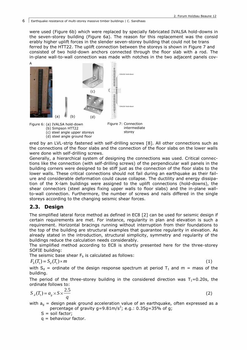
All connections were carried out with standard connectors. The shear forces were trans-
mitted by steel angles placed at regular intervals that connected the floor panels with the
upper wall panels (Figure 6; c+d). Hold-downs were used in the building corners and at
openings to accommodate the high uplift forces that can be generated by high horizontal
seismic loads (Figure 6, a+b). For the three-storey building, Simpson HTT22 hold-downs
2. Forum Holzbau Beaune 12
Earthquake resistance of multi-storey massive timber buildings | C. Sandhaas
6
were used (Figure 6b) which were replaced by specially fabricated IVALSA hold-downs in
the seven-storey building (Figure 6a). The reason for this replacement was the consid
erably higher uplift forces in the slender seven-storey building that could not be trans
ferred by the HTT22. The uplift connection between the storeys is shown in Figure 7 and
consisted of two hold-down anchors connected through the floor slab with a rod. The
in-plane wall-to-wall connection was made with notches in the two adjacent panels cov-
ered by an LVL-strip fastened with self-drilling screws [8]. All other connections such as
the connections of the floor slabs and the connection of the floor slabs on the lower walls
were done with self-drilling screws.
Generally, a hierarchical system of designing the connections was used. Critical connec-
tions like the connection (with self-drilling screws) of the perpendicular wall panels in the
building corners were designed to be stiff just as the connection of the floor slabs to the
lower walls. These critical connections should not fail during an earthquake as their fail-
ure and considerable deformation could cause collapse. The ductility and energy dissipa-
tion of the X-lam buildings were assigned to the uplift connections (hold-downs), the
shear connectors (steel angles fixing upper walls to floor slabs) and the in-plane wall-
to-wall connection. Furthermore, the number of screws and nails differed in the single
storeys according to the changing seismic shear forces.
2.3. Design
The simplified lateral force method as defined in EC8 [2] can be used for seismic design if
certain requirements are met. For instance, regularity in plan and elevation is such a
requirement. Horizontal bracings running without interruption from their foundations to
the top of the building are structural examples that guarantee regularity in elevation. As
already stated in the introduction, structural simplicity, symmetry and regularity of the
buildings reduce the calculation needs considerably.
The simplified method according to EC8 is shortly presented here for the three-storey
SOFIE building:
The seismic base shear Fb is calculated as follows:
1 1( ) ( )b dF T S T m (1)
with Sd = ordinate of the design response spectrum at period T1 and m = mass of the
building.
The period of the three-storey building in the considered direction was T1=0.20s, the
ordinate follows to:
1
2.5( )d gS T a S
q (2)
with ag = design peak ground acceleration value of an earthquake, often expressed as a
percentage of gravity g=9.81m/s2; e.g.: 0.35g=35% of g;
S = soil factor;
q = behaviour factor.
A
(a) (b)
(c)
(d)
IVALSA hold-down
142
IVALSA hold-down
Figure 6: (a) IVALSA hold-down (b) Simpson HTT22 (c) steel angle upper storeys (d) steel angle ground floor
Figure 7: Connection intermediate storey

2. Forum Holzbau Beaune 12
Earthquake resistance of multi-storey massive timber buildings | C. Sandhaas
7
The seismic base shear is then distributed in horizontal forces per storey:
i ii b
j j
z mF F
z m (3)
with zi, zj the heights of the masses mi, mj above the level where Fb acts (usually founda-
tions).
Afterwards, a „static” design applying the evaluated horizontal forces can be carried out.
Soil parameters, peak ground accelerations and design response spectra are defined in
seismic standards.
The relevant design parameter that is of interest for a timber engineer is the behaviour
factor q, Equation (2). In order to avoid complicated nonlinear calculations, a linear veri-
fication is carried out. The applicable seismic forces are reduced by the behaviour factor
q in order to account for the nonlinear response of the structure, associated with the ma-
terial, the structural system and the design procedures [2]. This q-factor has to be cho-
sen by the earthquake engineer for every building. In other words, the introduction of
the behaviour factor q simplifies the design calculations considerably as instead of com-
plex nonlinear calculations, linear verifications can be carried out with reduced forces that
account for the ductility and energy dissipation of the building. The design of the three-
storey SOFIE building from
Figure 2 has been carried out with the parameters for Italy. The design peak ground accel-
eration has been ag=0.35g, the highest PGA in Italy (in mainland France, aléa moyen ag
= 3 m/s2 = 0.3g), and the soil factor was S = 1.25. The initial design assumed a purely
elastic building with no energy dissipation. This means
that a q-factor q = 1.0 was used. If for instance, the q-factor would have been assumed
to be q = 2.0, then the seismic base shear would have been half the value shown in
Table 1. With the evaluated horizontal seismic forces as given in Table 1, the building
and the connections have been designed. Therefore, it is the behaviour factor q that has
to be determined in order to be able to design CLT buildings in seismic regions.
3. Shaking Table Tests
For the shaking table tests, FSC/PEFC certified spruce was transported from the Trentino
region to Germany where the CLT panels were produced. Afterwards, the panels and the
connectors were transported to Japan. Only one building per test (three and seven storeys)
was produced. The two buildings have been subjected to a whole series of earthquakes
Table 1: Seismic forces of three-storey building
Mass of the building
roof 45 kN
floor 2 210 kN
floor 1 210 kN
TOT 465 kN
seismic forces
seismic base shear
Zone 1; ag = 0.35
T1 0.20
Soil class B S= 1.25
q 1
Fb = 2,5*(W*S*ag)/q 509 kN
distribution on storeys
height
Zr (roof) = 9.40 m
Z2 (floor 2) = 6.18 m
Z1 (floor 1) = 3.09 m
horizontal forces per storey
Fr = 91 kN
F2 = 279 kN
F1 = 139 kN
shear per storey
Tr = 91 kN
T2 = 370 kN
T1 = 509 kN

2. Forum Holzbau Beaune 12
Earthquake resistance of multi-storey massive timber buildings | C. Sandhaas
8
and, if necessary, repaired in between. The chosen earthquakes were the Japanese Kobe
earthquake from 1995 (JMA Kobe), an Italian earthquake (Nocera Umbra 1997), the El
Centro quake as a reference earthquake for research (only three-storey building) and the
Kashiwazaki earthquake from July 2007 that occurred a couple of weeks before the tests
(only seven-storey building). All earthquakes were applied with small peak ground accel-
erations that were gradually increased in the course of the testing series. The single
earthquakes were followed by a so-called step input that subjected the buildings to free
vibrations. With a step input, the development of the eigenfrequencies of the buildings
could be measured and therewith the damage induced by the earthquakes.
Below, the original peak ground acceleration (PGA) values of the chosen earthquakes are
given:
JMA Kobe: North-South 0.82g, East-West 0.6g, Up-Down 0.34g
(three-storey building only N-S), magnitude 7.2 on Richter scale;
El Centro: 0.3g, magnitude 6.7 on Richter scale;
Nocera Umbra: 0.5g, magnitude 5.8 on Richter scale;
Kashiwazaki R1: North-South 0.68g, East-West 0.311g, Up-Down 0.408g
(seven-storey building), magnitude 6.8 on Richter scale.
3.1. Method to Determine Behaviour Factor q
An important concept in modern force-based seismic standards is the behaviour factor q.
As already stated, the q-factor reflects the capacity of buildings to dissipate energy through
nonlinear behaviour and thus to survive destructive seismic events without collapse (loss of
lives) – the so-called „near-collapse” state. The q-factor is determined by developing a
numerical model that is able to simulate the nonlinear response of structures (different
geometries and masses) subjected to different earthquakes. However, such a numerical
model is difficult to verify without experimental data. Therefore, for every „new” construc-
tion typology that should be inserted in seismic standards, tests must be carried out. The
experimental determination of the behaviour factor q is done as follows:
Design the structure using q = 1 according to the seismic code for a given design peak
ground acceleration ag (here 0.35g);
Define a near-collapse criterion, here the failure in hold-down anchors (one or more)
and increase the PGA until near-collapse is reached, ag,test;
Analyse the test results and calculate q as the ratio between the value ag,test that caused the near-collapse of the building and the design value ag.
This experimental approach gives an initial value for the behavior factor q that is valid
only for the tested building and the earthquake which caused the near-collapse state.
More information about design and determination of behavior factor q can be taken from
literature [9, 10]. However, an experimental approach gives a qualitative measurement
of the earthquake behaviour of a certain construction typology.
3.2. Measuring Techniques
A major challenge of full-scale shaking table tests is the question, which values should be
measured and how. The four main measured values are listed below:
Interstorey drift, measured from lower to upper floor slab (Figure 8);
Uplift at corner hold-downs (Figure 9);
Relative deformation of the in-plane wall-to-wall connection (Figure 10);
Accelerations in the different storeys (Figure 11).
The first three connections are designed to behave in a ductile mode and to dissipate
energy. The displacements of all other connections (i.e. between single floor slabs or at
wall corners) was designed to be small, no energy should be dissipated in these important
connections for structural safety. As already stated, this hierarchical design approach of

2. Forum Holzbau Beaune 12
Earthquake resistance of multi-storey massive timber buildings | C. Sandhaas
9
the connections should avoid failure in connections that could trigger collapse. However,
also there transducers were used to control the displacements and to verify that indeed
only very small displacements occurred as defined in the design.
Figure 8: Interstorey drift
Figure 9: Uplift
Figure 10: Relative slip in plane wall-to wall connection
Figure 11: Accelerometers
3.3. Testing Series and Results Three-Storey Building
The three-storey SOFIE building was tested in three configurations (
Figure 2). The near-collapse criterion could only be reached in the last asymmetric configu-
ration C as otherwise, the damage would have been too big already in configurations A
and B and it would not have been possible to continue testing. The near-collapse criterion
of the SOFIE criterion was the failure of one or more hold-downs.
The tests were carried out in July 2006 on the shaking table of the ’National Institute for
Earth Science and Disaster Prevention’ (NIED) in Tsukuba, Japan. The shaking table in
Tsukuba is one-dimensional, it can be moved only in one horizontal direction – the earth-
quake direction is indicated in
Figure 2. Table 2 lists the observed damage for all earthquakes with a PGA bigger than
0.5g in configuration C. Before testing configuration C, also configurations A and B were
already subjected to all three earthquakes with ag = 0.15g und ag = 0.5g. Also configura-
tion C was subjected to smaller earthquakes with a PGA of 0.15g – a total of 15 earth-
quakes were applied before configuration C was tested up to near-collapse. Until 0.15g,
no damage was observed in any configuration (no change of eigenfrequency) and the
observed damage at 0.5g was small and repairable.
Table 2: Results for configuration C and earthquakes from 0.5g
Record PGA [g] Restoring intervention
(before the test) Observed damage (after the test)
Nocera Umbra
0.50 Tightening of hold-down anchor bolts
None
El Centro 0.50 Tightening of hold-down anchor bolts. Replacing of screws in vertical joints between panel
None
JMA Kobe 0.50 Idem None
JMA Kobe 0.80 Idem
Slight deformation of screws in vertical joints between panels
JMA Kobe 0.50 Idem None
JMA Kobe 0.50 Tightening of hold-down anchor bolts
None
JMA Kobe 0.80 Replacing of hold-down anchors and tightening of bolts. Replacing
of screws in vertical joints
between panel
Slight deformation of screws in vertical joints between panels
Nocera Umbra
1.20 Tightening of hold-down anchor bolts. Replacing of screws in vertical joints between panel
Hold-down failure (see Figure 12) and deformation of screws in vertical
joints between panels

2. Forum Holzbau Beaune 12
Earthquake resistance of multi-storey massive timber buildings | C. Sandhaas
10
The near-collapse criterion was reached during the Nocera Umbra quake with
ag,test = 1.20g as can be seen in Table 2. The hold-down failure is shown in Figure 12. It
must be emphasised that the three-storey building survived a series of 12 destructive
earthquakes with peak ground accelerations of 0.5g and more without any major restor-
ing interventions. In reality, the building has to survive one single of these earthquakes
without collapsing. Even after Nocera Umbra 1.20g and hold-down failure, the building
did not collapse and remained standing without permanent deformations. No influence of
the asymmetric opening could be observed.
Figure 12: Hold-down failure after Nocera Umbra 1.20g
3.4. Determination of Behaviour Factor q
The design peak ground acceleration was ag = 0.35g. The near-collapse criterion was met
at a peak ground acceleration of ag,test = 1.20g. If now the above described method is
used, the q-factor can be determined to:
, 1.203.4
0.35
g test
g
aq
a (4)
The evaluated q-factor is valid only for the tested configuration and the earthquake of
Nocera Umbra. To derive a general q-factor for CLT buildings, a numerical model has
been developed [9] whose simulations with different earthquakes resulted in q-factors
between 3.0 and 4.57. However, still different geometries and building masses must be
simulated in order to derive a final reliable behaviour factor q.
However, a value of q = 3.4 is a good indication. Together with the test results it can be
concluded that CLT buildings show a good seismic resistance and that they are an ade-
quate construction technique for earthquake-prone regions. More conclusions can be
drawn after the shaking table test on the seven-storey building.
3.5. Testing Series and Results Seven-Storey Building
After the successful test series with a three-storey CLT building, a seven–storey CLT
building (Figure 4) was tested on the big shaking table of the NIED in Kobe, Japan, in
October 2007 – seven storeys because a higher building would not have fitted in the
laboratory. The 15x20 m shaking table is three-dimensional. Therefore, all three spatial
components of an earthquake, North-South, East-West and Up-Down, can be applied on
a structure.
The design of the seven-storey building was not carried out with q = 1, but with q = 3
instead. This value of 3 resulted from the test series on the three-storey building.

2. Forum Holzbau Beaune 12
Earthquake resistance of multi-storey massive timber buildings | C. Sandhaas
11
The testing series is listed in Table 3 and was reduced in comparison to the three-storey
building, only one configuration was tested. The three chosen earthquakes, JMA Kobe,
El Centro and Kashiwazaki, were firstly applied in 1D. The direction x as defined in Figure
3 corresponded to the North-South components acting along the long side of the building
whereas direction y, the short side, was subjected to the East-West components. After
the 1D quakes, the three earthquakes were applied with all three spatial components,
in 3D and their original intensity. Analogously to the series on the three-storey building,
a step input was applied between the earthquakes to observe the development of the
eigenfrequencies and thus the damage. The percentages after the earthquake name and
used spatial component in Table 3 indicate the scaling of the earthquakes, i.e. whether
they have been applied at 100% intensity and their original PGA or if the PGA has been
scaled.
Similar to the previous tests, also here no significant damage has been observed up to
near-collapse, i.e. failure of one or more hold-downs. After the 3D tests, the bolts of the
hold-downs had to be tightened and some nails in the shear angles close to building cor-
ners and openings had been withdrawn and needed to be re-inserted. Furthermore, when
dismantling the building, no bending of the screws in the in-plane wall-to-wall joints
could be observed.
Also the seven-storey building could withstand a whole series of large earthquakes al-
though it had been designed with a behaviour factor of q = 3, reducing the seismic forces
in comparison to a purely elastic behaviour. No permanent deformations could be ob-
served, the building remained standing and kept its shape. The damaged connections
could be repaired. Apart from embedment in the connections, the CLT elements were not
damaged.
The measured deformation values for uplift and interstorey drift did not result in critical
values in comparison to the preliminary test results on wall elements. For instance, the
maximum uplift value on ground floor during the 3D JMA Kobe earthquake at 100% in-
tensity resulted to 13 mm. This is a smaller value than the deformation at failure of
30 mm that was observed during the preliminary tests on the wall elements.
Table 3: Testing series seven-storey building
in x in y in z
step 2D 0.3g 0.3g -
Nocera Umbra O-W 1D 70% - 0.35g -
Nocera Umbra O-W 1D 100% - 0.5g -
JMA Kobe N-S 1D 60% - 0.5g -
JMA Kobe O-W 1D 50% 0.3g - -
step 2D 0.3g 0.3g -
JMA Kobe N-S 1D 100% - 0.82g -
step 2D 0.3g 0.3g -
JMA Kobe O-W 1D 100% 0.6g -
step 2D 0.3g 0.3g -
step 2D 0.3g 0.3g -
JMA Kobe 3D 100% 0.6g 0.82g 0.34g
step 2D 0.3g 0.3g -
step 2D 0.3g 0.3g -
Kashiwazaki R1 3D 50% 0.155g 0.34g 0.204g
step 2D 0.3g 0.3g -
step 2D 0.3g 0.3g -
JMA Kobe 3D 100% 0.6g 0.82g 0.34g
step 2D 0.3g 0.3g -
step 2D 0.3g 0.3g -
Kashiwazaki R1 3D 100% 0.311g 0.68g 0.408g
step 2D 0.3g 0.3g -
PGAinput

2. Forum Holzbau Beaune 12
Earthquake resistance of multi-storey massive timber buildings | C. Sandhaas
12
4. Final discussion
Both shaking table tests confirmed the earthquake resistance of CLT buildings. Neither
the three-storey building nor the seven-storey building were seriously damaged. No per-
manent deformations could be observed after all tests although the buildings were sub-
jected to a whole series of major earthquakes with peak ground accelerations of 0.5g and
more. Furthermore, by means of the test results on the three-storey building, an indica-
tive value for the behaviour factor q could be derived with whom earthquake engineers
are able to carry out a simple and straightforward seismic design. With this indicative
behaviour factor of q = 3, the seven-storey building was designed which could equally
sustain a whole series of destructive earthquakes. With the test results on the seven-
storey building and a numerical model, the indicative value of q = 3 could be confirmed.
Other researchers also confirm the results and the generally good behaviour of CLT build-
ings under earthquake loading [11].
5. Acknowledgements
The earthquake team of the SOFIE project consisted of the following people:
Prof. Ario Ceccotti (head of research), Gabriele Bonamini, Marco Pio Lauriola, Maurizio
Follesa, Mario Pinna, Giovanna Franch, Mario Moschi.
Thanks to the Autonomous Province of Trento who financed the SOFIE project.
Special thanks go to our Japanese colleagues without whom the project would not have
been possible, Dr. Chikahiro Minowa from NIED, Prof. Motoi Yasumura from the Universi-
ty of Shizuoka, Dr Minoru Okabe from Centre for Better Living and Dr Naohito Kawai from
Building Research Institute.
Furthermore, thanks go to the company Rothoblaas from Kurtatsch, in Italy, for the fab-
rication and participation in the development of the IVALSA hold-down and to the com-
pany Simpson for the HTT-hold-downs.
6. References
[1] http://www.planseisme.fr. Décret n° 2010-1255 du 22 octobre 2010 portant délimitation des zones de sismicité du territoire français.
[2] EN 1998-1:2004, Eurocode 8: Design of structures for earthquake resistance – Part 1: General rules, seismic actions and rules for buildings, CEN, 2004
[3] Erdbebengerechtes Entwerfen und Konstruieren von mehrgeschossigen Holzbauten, Ligna-tec No. 23, Editor Lignum Switzerland, ISSN 1421-0320, 2008
[4] Ceccotti A, Lauriola M P, Pinna M, Sandhaas C, SOFIE Project – Cyclic Tests on Cross-
Laminated Wooden Panels, Proceedings WCTE, Portland, USA, 2006
[5] Sandhaas C, Projekt SOFIE – Erdbebenverhalten von Häusern aus XLAM, Proceedings Gra-zer Holzbaufachtagung, Graz, Austria, 2006
[6] Lauriola M P, Sandhaas C, Quasi-static and Pseudo-Dynamic Tests on XLAM Walls and Buildings, Proceedings COST ACTION E29, Coimbra, Portugal, 2006
[7] EN 1990:2002, Eurocode 0: Basis of structural design, CEN, 2002
[8] Sandhaas C, Van de Kuilen J-W G, Boukes J, Ceccotti A, Analysis of X-lam Panel-to-Panel Connections under Monotonic and Cyclic Loading, Proceedings CIB-W18 Meeting 42, Paper 42-12-2, Dübendorf, Switzerland, 2009
[9] Ceccotti A, New Technologies for Construction of Medium-Rise Buildings in Seismic Regions: The XLAM Case, Structural Engineering International, Volume 18, Number 2, Seiten 156-165, 2008
[10] Ceccotti A, Yasumura M, Minowa C, Lauriola M P, Follesa M, Sandhaas C, Which Seismic
Behaviour Factor for Multi-Storey Buildings made of Cross-Laminated Wooden Panels?, Pro-ceedings CIB W18 Meeting 39, Paper 39-15-2, Florence, Italy, 2006
[11] Dujič B, Hristovski V, Stojmanovska M, Žarnić R, Experimental investigation of massive wooden wall panel systems subjected to seismic excitation, Proceedings First European
Conference on Earthquake Engineering and Seismology, Genf, Switzerland, 2006
More information on the SOFIE project: www.progettosofie.it
Information on the 3D shaking table: www.bosai.go.jp/hyogo/ehyogo/index.html