EARTHING CONSTRUCTION MANUAL - UK Power Networks...planner/designer and the earthing construction...
22
EARTHING CONSTRUCTION MANUAL SECTION 3 SECONDARY DISTRIBUTION NETWORK EARTHING CONSTRUCTION
Transcript of EARTHING CONSTRUCTION MANUAL - UK Power Networks...planner/designer and the earthing construction...
EARTHING CONSTRUCTION MANUAL
SECTION 3
SECONDARY DISTRIBUTION NETWORK EARTHING CONSTRUCTION
EARTHING CONSTRUCTION MANUAL SECTION 3 - SECONDARY DISTRIBUTION NETWORK EARTHING CONSTRUCTION
25/10/2010 © UK Power Networks 2010 All rights reserved
HISTORY
Version Date Description Originator
1 20/02/2009 Original Stephen Tucker
1.1 09/04/2009 Legal Notice removed John Lowe
2.0 20/10/2010 Document rebranded Mariann Mulligan
EARTHING CONSTRUCTION MANUAL SECTION 3 - SECONDARY DISTRIBUTION NETWORK EARTHING CONSTRUCTION
25/10/2010 © UK Power Networks 2010 All rights reserved
CONTENTS
3.1 SCOPE.......................................................................................................................................4
3.2 GROUND-MOUNTED SUBSTATION EARTHING ...................................................................5
3.3 POLE-MOUNTED EARTHING ................................................................................................15
3.4 LV EARTHING.........................................................................................................................16
3.5 EARTH ELECTRODE OPTIONS ............................................................................................17
3.6 MATERIALS LIST ...................................................................................................................18
3.7 CONNECTION TECHNIQUES ................................................................................................19
3.8 MEASUREMENTS...................................................................................................................20
3.9 EARTHING BACKGROUND INFORMATION ........................................................................21
3.10 DEFINITIONS ..........................................................................................................................22
EARTHING CONSTRUCTION MANUAL SECTION 3 - SECONDARY DISTRIBUTION NETWORK EARTHING CONSTRUCTION
25/10/2010 © UK Power Networks 2010 All rights reserved
3.1 SCOPE
The earthing construction manual provides guidance for field staff on the practical application of earthing and applies to:
New secondary substations. Switchgear replacement at secondary substations. Fencing replacement at secondary substations. Existing substations where a material alteration is to take place, eg an increase in fault level etc.
This document includes the following sections:
1. Scope (this section). 2. Ground-mounted substation earthing - standard earthing requirements and designs. 3. Pole-mounted equipment earthing - reserved for future use. 4. LV earthing (reserved for future use). 5. Earth electrode options - vertical earth rod and horizontal conductor options to achieve desired
resistance values in various soil types. 6. Materials list. 7. Construction techniques. 8. Measurements (reserved for future use). 9. Purpose of earthing - a brief description of what happens during an earth fault and why earthing is
required. 10. Definitions - a list of definitions and terms used in this document.
This document does not cover the requirements of special situations, including:
Construction sites. Agricultural and horticultural premises. Caravan/camping parks.
The earthing construction manual is not a substitute for the earthing design manual which covers the earthing design in detail. In general the earthing design should be provided by the project planner/designer and the earthing construction manual can then be used to apply the design. However, if detailed design information is not available this manual can also be used to install an appropriate earthing system.
Modern materials, in particular polymeric cables, mean that earthing requires greater consideration than before. In the past, potential grading and a reduction in the earth resistance were convenient by-products of metallic sheathed cable systems. The use of polymeric cables means this contribution can no longer be relied upon and as a consequence higher voltages may appear on the site during an earth fault.
Refer to Section 3.9 for further information.

EARTHING CONSTRUCTION MANUAL SECTION 3 - SECONDARY DISTRIBUTION NETWORK EARTHING CONSTRUCTION
25/10/2010 © UK Power Networks 2010 All rights reserved
3.2 GROUND-MOUNTED SUBSTATION EARTHING
3.2.1 PROCESS
The design of earthing for new secondary ground-mounted substations should be carried out by the designer/planner to ensure that the design criteria outlined in Section 4 of the new earthing design manual are fulfilled. However, if detailed design information is not available or for existing sites this manual can be used to install an appropriate earthing system.
The designer/planner should provide the following for each project:
An earthing design form specifying the required HV earth resistance, and whether the HV and LV earths are to be combined (for COLD sites) or segregated (for HOT sites).
An earthing drawing based on one of the standard layouts.
Using the available information:
1. Install the earthing as detailed on the drawing provided by the project designer/planner or, if this is not available, select a suitable arrangement from Section 3.2.4 and apply the requirements of Section 3.2.1.1.
2. Apply the earthing requirements shown in Section 3.2.2 to the earthing arrangement. 3. Select the materials and connections from Sections 3.6 and 3.7. 4. Measure the values of the HV and (if segregated) LV earths in accordance with Section 3.8 to
confirm that the required earth resistance has been achieved.
3.2.1.1 INTERIM EARTHING DESIGN
Until the earthing design manual is updated designers/planners will not be able to provide the required value of HV earth resistance and whether the site is COLD or HOT. As an interim solution the following criteria can be applied:
1. The substation must be assumed to be HOT unless it is fed from the source substation by a continuous underground cable.
2. The HV earth must have a maximum resistance of 1 unless it is a compact or micro substation fed by overhead line when a maximum HV earth resistance of 10 should be used.
3.2.2 GENERAL EARTHING REQUIREMENTS
The sections below detail the common earthing requirements that should be applied with the earthing layouts in Section 3.2.4.
3.2.2.1 HV ELECTRODE
Bare copper cable and copper clad or galvanised rods are used as earth electrodes.
For earth fault levels up to 8kA use 70mm2 bare stranded copper cable. For earth fault levels greater than 8kA use 120mm2 (or 2 x 70mm2) bare stranded copper cable. HV rod electrode should be made up from 1m or 1.2m copper clad or galvanised rods.
Note - in ground types expected to have high resistivity (eg sand/gravel/slate/shale/rock) additional HV electrode may be needed to achieve the required resistance to earth. In these instances it is advisable to install horizontal bare copper electrode and earth rods (from Section 3.5) in a cable trench at least 200mm underneath an HV cable (or if not possible alongside the HV cable).

EARTHING CONSTRUCTION MANUAL SECTION 3 - SECONDARY DISTRIBUTION NETWORK EARTHING CONSTRUCTION
25/10/2010 © UK Power Networks 2010 All rights reserved
3.2.2.2 BONDING
All main items of plant (LV boards, ACBs, RTUs etc) must be bonded to the main transformer or switchgear earth terminal.
For earth fault levels up to 8kA use 70mm2 PVC covered stranded copper cable. For earth fault levels greater than 8kA use 120mm2 PVC covered stranded copper cable. For surface mounting in indoor substations an alternative is 25mm x 6mm (or larger) aluminium
tape.
3.2.2.3 HV CABLES
All cable earth screens must be bonded to the transformer or switchgear earth terminal in accordance with Section 4 of the 11kV Cable Jointing Manual.
3.2.2.4 LV CABLES
CNE cables - the outer sheath of the cable must be connected to the neutral bar in the LV pillar/cabinet in accordance with Section 4 of the LV Cable Jointing Manual.
SNE cables - the outer sheath and armouring must be bonded together and connected to the neutral bar in the LV pillar/cabinet. The neutral conductor must be connected to the neutral bar in the LV pillar/cabinet. This must be completed in accordance with Section 4 of the LV Cable Jointing Manual.
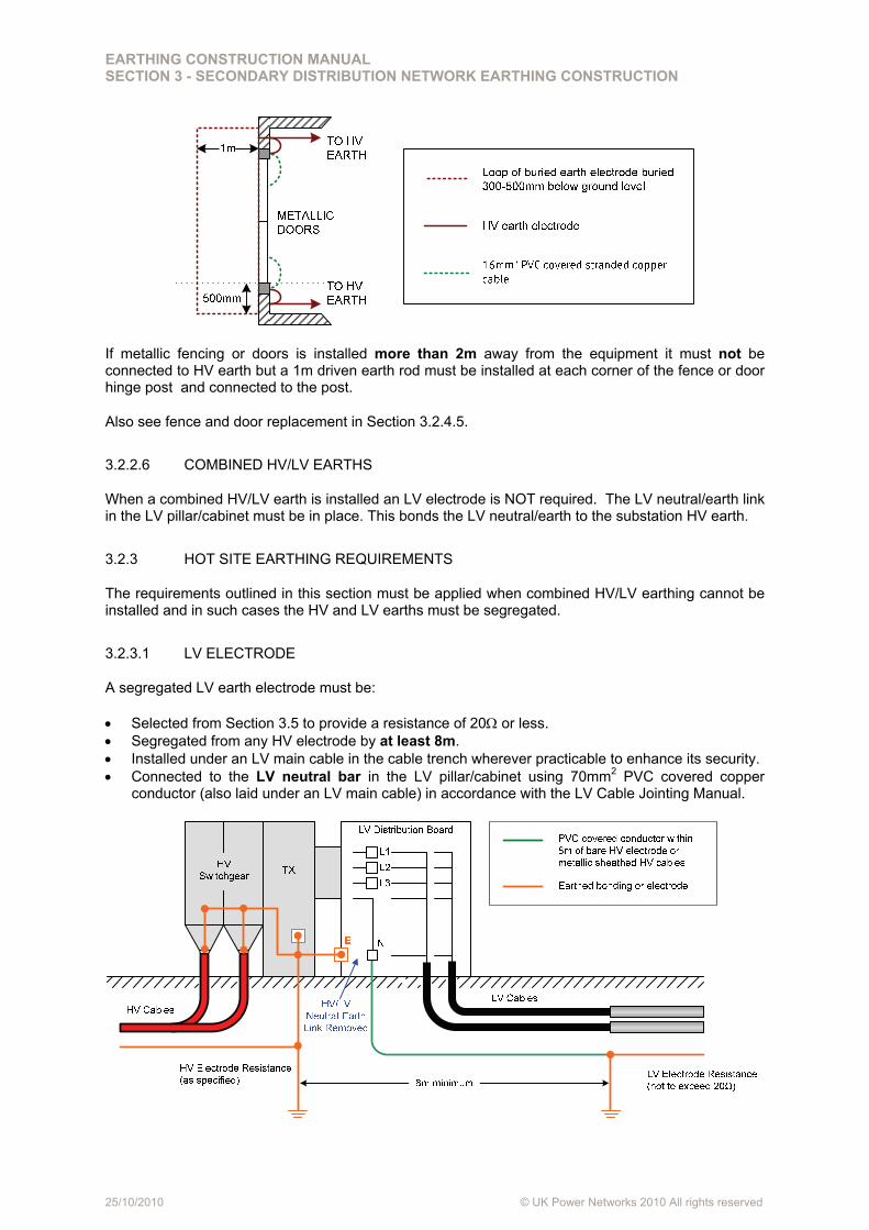
3.2.2.5 FENCING AND DOORS
If a metallic fence is installed within 2m of equipment:
It must be connected to the HV earth and A grading electrode of 70mm2 bare copper cable must as a minimum be installed under the
fence line, or just inside, ideally at a depth of 500mm (300mm minimum) and connected to the fence in order to protect staff and the public from dangerous touch potentials. If practicable the grading electrode should be installed outside the fence at a distance of 300-500mm away from the fence.
If metallic doors are installed within 2m of equipment:
A loop of 70mm2 bare copper cable must as a minimum be installed directly under the door at a depth of 300mm to 500mm. If practicable it should be outside the door, 1m from the door front and 500mm beyond each door frame as shown below. Each end of the loop must be connected to the existing HV electrode and be covered with a 100mm thickness of concrete to provide protection against damage or theft.
Alternatively, a steel or copper mesh may be installed in concrete to depth of 200mm to 300mm, covering the same area as above.
Each metal door must be bonded to the framework (if metallic), and to the HV earth using flexible 16mm2 PVC covered stranded copper cable.
EARTHING CONSTRUCTION MANUAL SECTION 3 - SECONDARY DISTRIBUTION NETWORK EARTHING CONSTRUCTION
25/10/2010 © UK Power Networks 2010 All rights reserved
If metallic fencing or doors is installed more than 2m away from the equipment it must not be connected to HV earth but a 1m driven earth rod must be installed at each corner of the fence or door hinge post and connected to the post.
Also see fence and door replacement in Section 3.2.4.5.
3.2.2.6 COMBINED HV/LV EARTHS
When a combined HV/LV earth is installed an LV electrode is NOT required. The LV neutral/earth link in the LV pillar/cabinet must be in place. This bonds the LV neutral/earth to the substation HV earth.
3.2.3 HOT SITE EARTHING REQUIREMENTS
The requirements outlined in this section must be applied when combined HV/LV earthing cannot be installed and in such cases the HV and LV earths must be segregated.
3.2.3.1 LV ELECTRODE
A segregated LV earth electrode must be:
Selected from Section 3.5 to provide a resistance of 20 or less. Segregated from any HV electrode by at least 8m. Installed under an LV main cable in the cable trench wherever practicable to enhance its security. Connected to the LV neutral bar in the LV pillar/cabinet using 70mm2 PVC covered copper
conductor (also laid under an LV main cable) in accordance with the LV Cable Jointing Manual.

EARTHING CONSTRUCTION MANUAL SECTION 3 - SECONDARY DISTRIBUTION NETWORK EARTHING CONSTRUCTION
25/10/2010 © UK Power Networks 2010 All rights reserved
3.2.3.2 NEUTRAL-EARTH LINK
The HV/LV neutral-earth link must be removed for a segregated HV/LV earth.
3.2.3.3 WARNING NOTICES FOR SEGREGATED EARTHS
Where the HV and LV earths are segregated, warning notices as detailed below are required.
Label Type Label Text Location Stores Code
Plate Separate HV & LV Earths Install in prominent position inside fence/enclosure
19208X
Plate Do Not Close Earth Link between Separate HV & LV Earths
Install in LV equipment adjacent to LV Neutral - HV earth link
19210L
Plate
CAUTION:
Separate HV & LV Earths Treat LV Neutral as Live
Install in LV cabinet or next to fuse board in close proximity to LV neutral
Not currently available - procure locally1
Adhesive Label
Wear HV Rubber Gloves to Operate
On HV switchgear near operating position
19209G
3.2.3.4 LIGHTING AND SOCKET SUPPLIES
Care must also be taken with lighting and socket supplies to avoid operator contact between different earthing systems. Therefore at HOT sites:
Metallic light switches, 13A sockets and conduits must not be installed within 2m of any metalwork bonded to the HV earth.
13A sockets must be removed from transformer mounted fuse cabinets, LV pillars and LV boards unless the earth terminal is connected to the HV earth and an RCD is provided.
1 These labels will be added as stores items in the future.
EARTHING CONSTRUCTION MANUAL SECTION 3 - SECONDARY DISTRIBUTION NETWORK EARTHING CONSTRUCTION
25/10/2010 © UK Power Networks 2010 All rights reserved
3.2.3.5 STREET LIGHTING COLUMNS
Metal street lighting columns within 2m of a HOT site must have their columns earthed via a separate earth rod installed adjacent to the column and not use the neutral/earth of a PME supply.
3.2.4 SECONDARY SUBSTATION EARTHING DESIGNS
The section contains general earthing arrangements designs, showing the installation of the HV and LV (if required) earthing electrode, for the following types of ground-mounted secondary substation:
Standard GRP substations. Fully-bunded GRP substations. Brick-built substations. Compact and micro pad-mount outdoor substations. Existing outdoor substations. Fence and door replacement.
These are based on the following standard substation design drawings contained in EI 07-0102.
Standard GRP enclosure unit/package substation EI 07-0102-0002 Standard GRP compact substation EI 07-0102-0012 Standard GRP micro/pad-mount unit substation EI 07-0102-0008 Standard GRP HV metering substation EI 07-0102-0006 Fully-bunded GRP enclosure unit/package substation EI 07-0102-0004 Fully-bunded GRP compact substation EI 07-0102-0014 Brick-built unit/package substation EI 07-0102-0017 Brick-built unit/package substation with ACB EI 07-0102-0020 Double brick-built unit substation EI 07-0102-0023 Compact and micro/pad-mount outdoor substations EI 07-0102-0024 Connection techniques EI 07-0102-0025
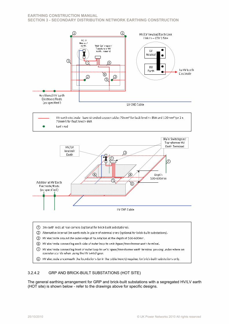
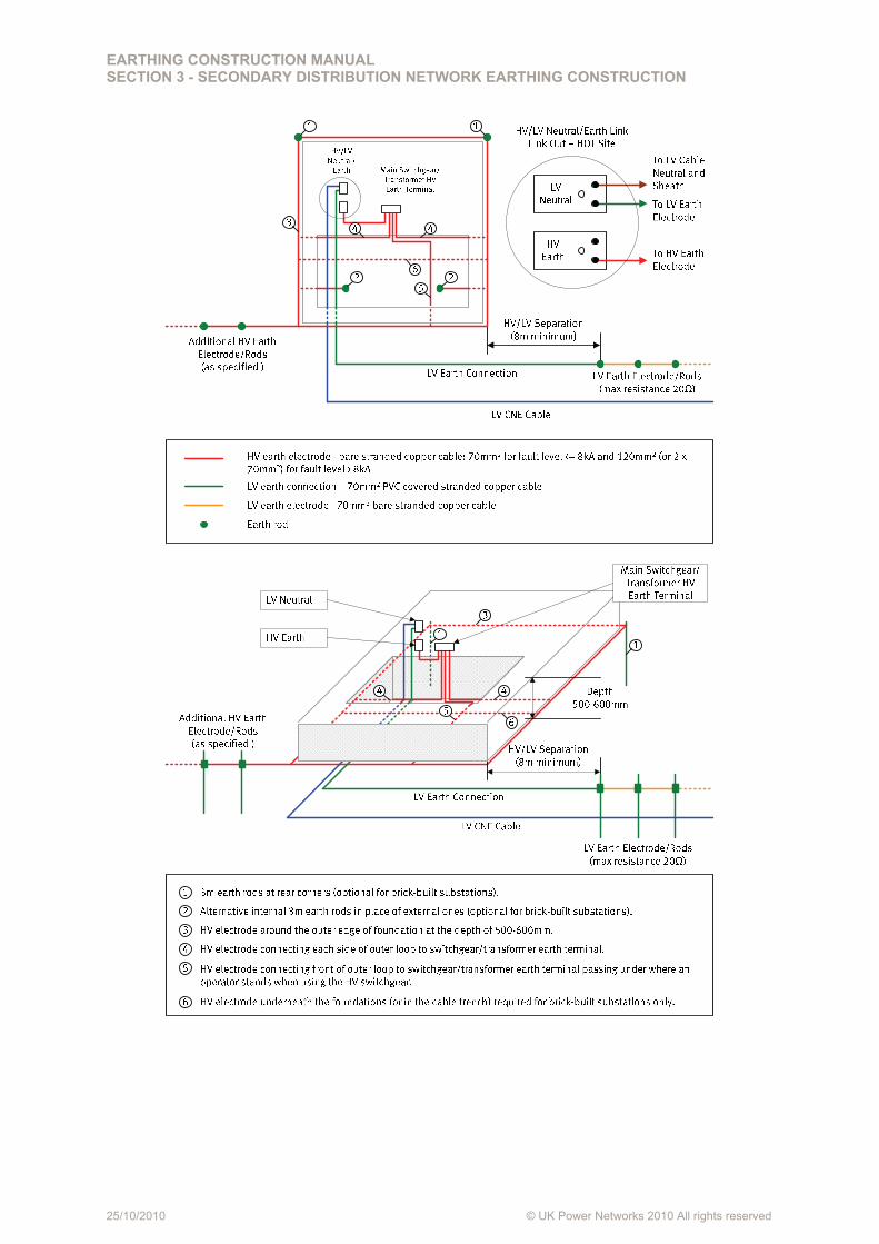
3.2.4.1 GRP AND BRICK-BUILT SUBSTATIONS (COLD SITE)
The general earthing arrangement for GRP and brick-built substations with a combined HV/LV earth (COLD site) is shown below - refer to the drawings above for specific designs.
EARTHING CONSTRUCTION MANUAL SECTION 3 - SECONDARY DISTRIBUTION NETWORK EARTHING CONSTRUCTION
25/10/2010 © UK Power Networks 2010 All rights reserved
3.2.4.2 GRP AND BRICK-BUILT SUBSTATIONS (HOT SITE)
The general earthing arrangement for GRP and brick-built substations with a segregated HV/LV earth (HOT site) is shown below - refer to the drawings above for specific designs.
EARTHING CONSTRUCTION MANUAL SECTION 3 - SECONDARY DISTRIBUTION NETWORK EARTHING CONSTRUCTION
25/10/2010 © UK Power Networks 2010 All rights reserved
EARTHING CONSTRUCTION MANUAL SECTION 3 - SECONDARY DISTRIBUTION NETWORK EARTHING CONSTRUCTION
25/10/2010 © UK Power Networks 2010 All rights reserved
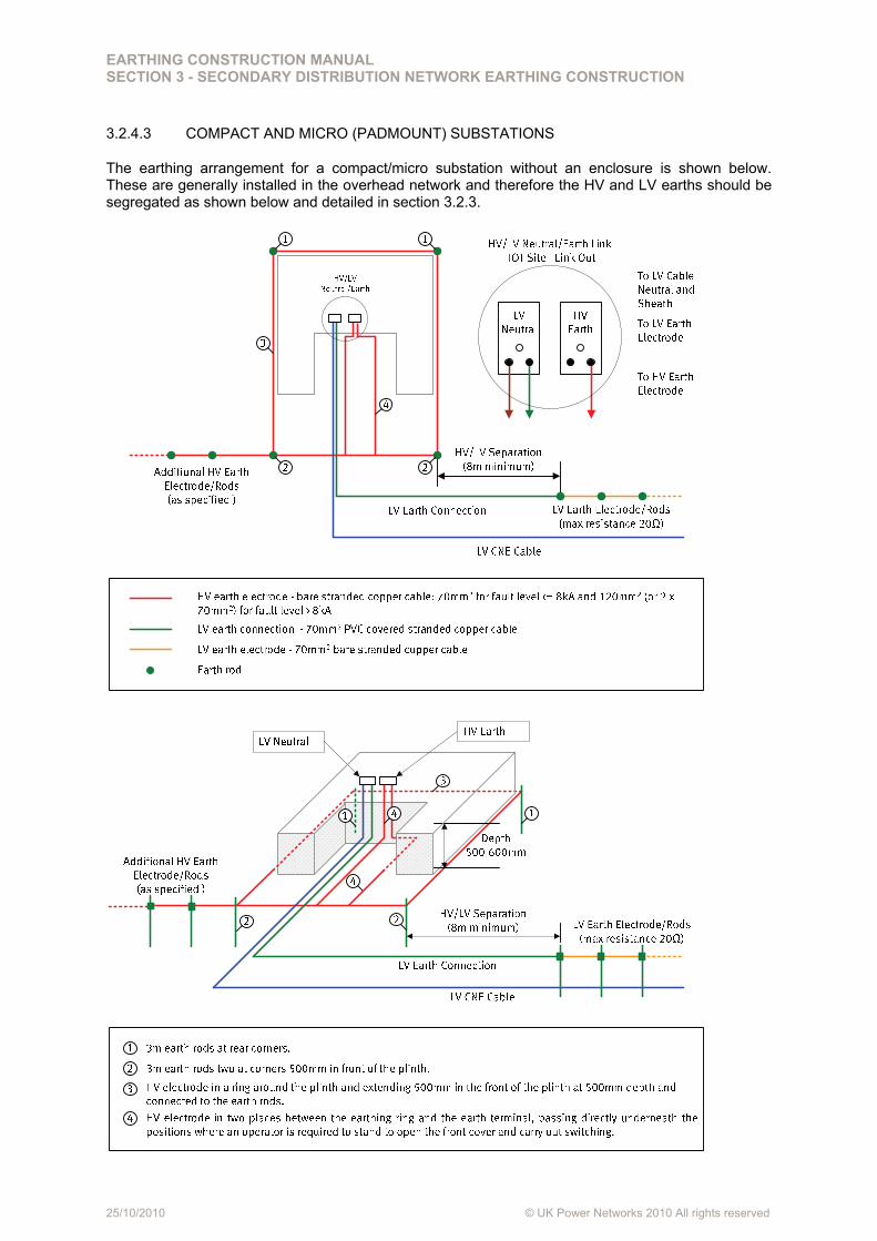
3.2.4.3 COMPACT AND MICRO (PADMOUNT) SUBSTATIONS
The earthing arrangement for a compact/micro substation without an enclosure is shown below. These are generally installed in the overhead network and therefore the HV and LV earths should be segregated as shown below and detailed in section 3.2.3.
EARTHING CONSTRUCTION MANUAL SECTION 3 - SECONDARY DISTRIBUTION NETWORK EARTHING CONSTRUCTION
25/10/2010 © UK Power Networks 2010 All rights reserved
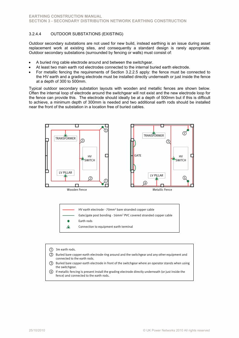
3.2.4.4 OUTDOOR SUBSTATIONS (EXISTING)
Outdoor secondary substations are not used for new build, instead earthing is an issue during asset replacement work at existing sites, and consequently a standard design is rarely appropriate. Outdoor secondary substations (surrounded by fencing or walls) must consist of:
A buried ring cable electrode around and between the switchgear. At least two main earth rod electrodes connected to the internal buried earth electrode. For metallic fencing the requirements of Section 3.2.2.5 apply: the fence must be connected to
the HV earth and a grading electrode must be installed directly underneath or just inside the fence at a depth of 300 to 500mm.
Typical outdoor secondary substation layouts with wooden and metallic fences are shown below. Often the internal loop of electrode around the switchgear will not exist and the new electrode loop for the fence can provide this. The electrode should ideally be at a depth of 500mm but if this is difficult to achieve, a minimum depth of 300mm is needed and two additional earth rods should be installed near the front of the substation in a location free of buried cables.
HV earth electrode - 70mm2 bare stranded copper cable
Gate/gate post bonding - 16mm2 PVC covered stranded copper cable
Earth rods
Connection to equipment earth terminal
GATE HV SWITCH
LV PILLAR
Metallic Fence
HV SWITCH
TRANSFORMER
LV PILLAR
Wooden Fence
TRANSFORMER
Buried bare copper earth electrode in front of the switchgear where an operator stands when using the switchgear.
3m earth rods.
Buried bare copper earth electrode ring around and the switchgear and any other equipment and connected to the earth rods.
1
3
2
1
3 3
1
1
1
2
If metallic fencing is present install the grading electrode directly underneath (or just inside the fence) and connected to the earth rods.
4
4
EARTHING CONSTRUCTION MANUAL SECTION 3 - SECONDARY DISTRIBUTION NETWORK EARTHING CONSTRUCTION
25/10/2010 © UK Power Networks 2010 All rights reserved
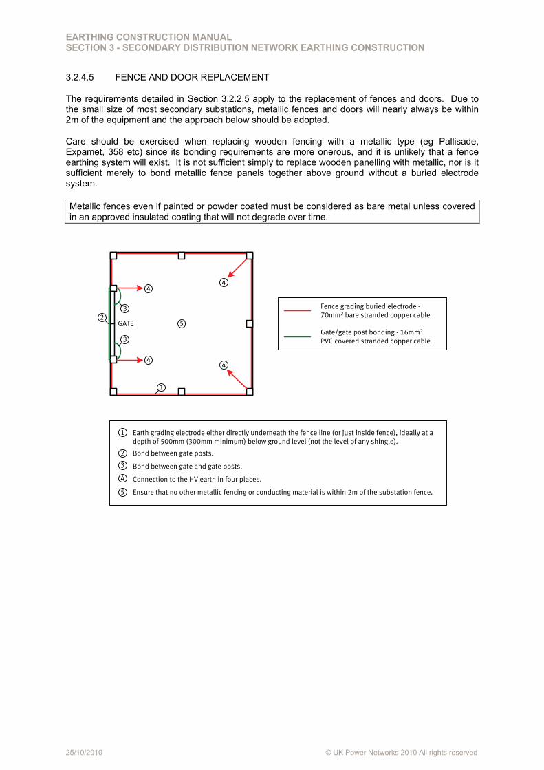
3.2.4.5 FENCE AND DOOR REPLACEMENT
The requirements detailed in Section 3.2.2.5 apply to the replacement of fences and doors. Due to the small size of most secondary substations, metallic fences and doors will nearly always be within 2m of the equipment and the approach below should be adopted.
Care should be exercised when replacing wooden fencing with a metallic type (eg Pallisade, Expamet, 358 etc) since its bonding requirements are more onerous, and it is unlikely that a fence earthing system will exist. It is not sufficient simply to replace wooden panelling with metallic, nor is it sufficient merely to bond metallic fence panels together above ground without a buried electrode system.
Metallic fences even if painted or powder coated must be considered as bare metal unless covered in an approved insulated coating that will not degrade over time.
GATEGate/gate post bonding - 16mm2
PVC covered stranded copper cable
Fence grading buried electrode -70mm2 bare stranded copper cable
Bond between gate and gate posts.
Earth grading electrode either directly underneath the fence line (or just inside fence), ideally at a depth of 500mm (300mm minimum) below ground level (not the level of any shingle).
Bond between gate posts.
1
3
2
Connection to the HV earth in four places.4
Ensure that no other metallic fencing or conducting material is within 2m of the substation fence.5
1
2
3
3
4
44
4
5
EARTHING CONSTRUCTION MANUAL SECTION 3 - SECONDARY DISTRIBUTION NETWORK EARTHING CONSTRUCTION
25/10/2010 © UK Power Networks 2010 All rights reserved
3.3 POLE-MOUNTED EARTHING
Reserved for future use - refer to the pole-mounted section of the earthing design manual.
EARTHING CONSTRUCTION MANUAL SECTION 3 - SECONDARY DISTRIBUTION NETWORK EARTHING CONSTRUCTION
25/10/2010 © UK Power Networks 2010 All rights reserved
3.4 LV EARTHING
Reserved for future use - refer to the LV section of the earthing design manual.
EARTHING CONSTRUCTION MANUAL SECTION 3 - SECONDARY DISTRIBUTION NETWORK EARTHING CONSTRUCTION
25/10/2010 © UK Power Networks 2010 All rights reserved
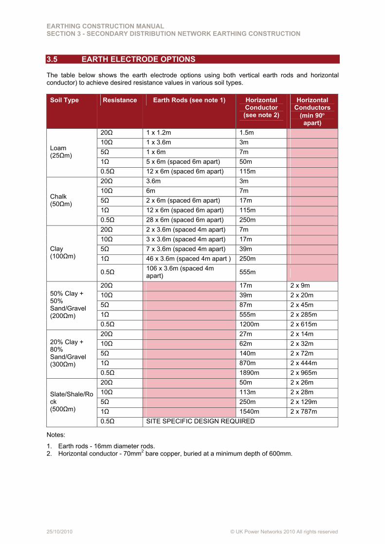
3.5 EARTH ELECTRODE OPTIONS
The table below shows the earth electrode options using both vertical earth rods and horizontal conductor) to achieve desired resistance values in various soil types.
Soil Type Resistance Earth Rods (see note 1) Horizontal Conductor (see note 2)
Horizontal Conductors
(min 90 apart)
20Ω 1 x 1.2m 1.5m
10Ω 1 x 3.6m 3m
5Ω 1 x 6m 7m
1Ω 5 x 6m (spaced 6m apart) 50m
Loam (25Ωm)
0.5Ω 12 x 6m (spaced 6m apart) 115m
20Ω 3.6m 3m
10Ω 6m 7m
5Ω 2 x 6m (spaced 6m apart) 17m
1Ω 12 x 6m (spaced 6m apart) 115m
Chalk (50Ωm)
0.5Ω 28 x 6m (spaced 6m apart) 250m
20Ω 2 x 3.6m (spaced 4m apart) 7m
10Ω 3 x 3.6m (spaced 4m apart) 17m
5Ω 7 x 3.6m (spaced 4m apart) 39m
1Ω 46 x 3.6m (spaced 4m apart ) 250m
Clay (100Ωm)
0.5Ω 106 x 3.6m (spaced 4m apart)
555m
20Ω 17m 2 x 9m
10Ω 39m 2 x 20m
5Ω 87m 2 x 45m
1Ω 555m 2 x 285m
50% Clay + 50% Sand/Gravel (200Ωm)
0.5Ω 1200m 2 x 615m
20Ω 27m 2 x 14m
10Ω 62m 2 x 32m
5Ω 140m 2 x 72m
1Ω 870m 2 x 444m
20% Clay + 80% Sand/Gravel (300Ωm)
0.5Ω 1890m 2 x 965m
20Ω 50m 2 x 26m
10Ω 113m 2 x 28m
5Ω 250m 2 x 129m
1Ω 1540m 2 x 787m
Slate/Shale/Rock (500Ωm)
0.5Ω SITE SPECIFIC DESIGN REQUIRED
Notes:
1. Earth rods - 16mm diameter rods. 2. Horizontal conductor - 70mm2 bare copper, buried at a minimum depth of 600mm.
EARTHING CONSTRUCTION MANUAL SECTION 3 - SECONDARY DISTRIBUTION NETWORK EARTHING CONSTRUCTION
25/10/2010 © UK Power Networks 2010 All rights reserved
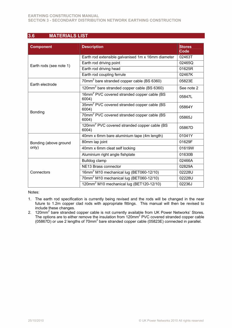
3.6 MATERIALS LIST
Component Description Stores Code
Earth rod extensible galvanised 1m x 16mm diameter 02463T
Earth rod driving point 02465Q
Earth rod driving head 01625R Earth rods (see note 1)
Earth rod coupling ferrule 02467K
70mm2 bare stranded copper cable (BS 6360) 05823E Earth electrode
120mm2 bare stranded copper cable (BS 6360) See note 2
16mm2 PVC covered stranded copper cable (BS 6004)
05847L
35mm2 PVC covered stranded copper cable (BS 6004)
05864Y
70mm2 PVC covered stranded copper cable (BS 6004)
05865J Bonding
120mm2 PVC covered stranded copper cable (BS 6004)
05867D
40mm x 6mm bare aluminium tape (4m length) 01041Y
80mm lap joint 01629F
40mm x 6mm cleat self locking 01619W Bonding (above ground only)
Aluminium right angle fishplate 01630B
Bulldog clamp 02466A
NE13 Brass connector 02829A
16mm2 M10 mechanical lug (BET060-12/10) 02228U
70mm2 M10 mechanical lug (BET060-12/10) 02228U
Connectors
120mm2 M10 mechanical lug (BET120-12/10) 02236J
Notes:
1. The earth rod specification is currently being revised and the rods will be changed in the near future to 1.2m copper clad rods with appropriate fittings. This manual will then be revised to include these changes.
2. 120mm2 bare stranded copper cable is not currently available from UK Power Networks’ Stores. The options are to either remove the insulation from 120mm2 PVC covered stranded copper cable (05867D) or use 2 lengths of 70mm2 bare stranded copper cable (05823E) connected in parallel.
EARTHING CONSTRUCTION MANUAL SECTION 3 - SECONDARY DISTRIBUTION NETWORK EARTHING CONSTRUCTION
25/10/2010 © UK Power Networks 2010 All rights reserved
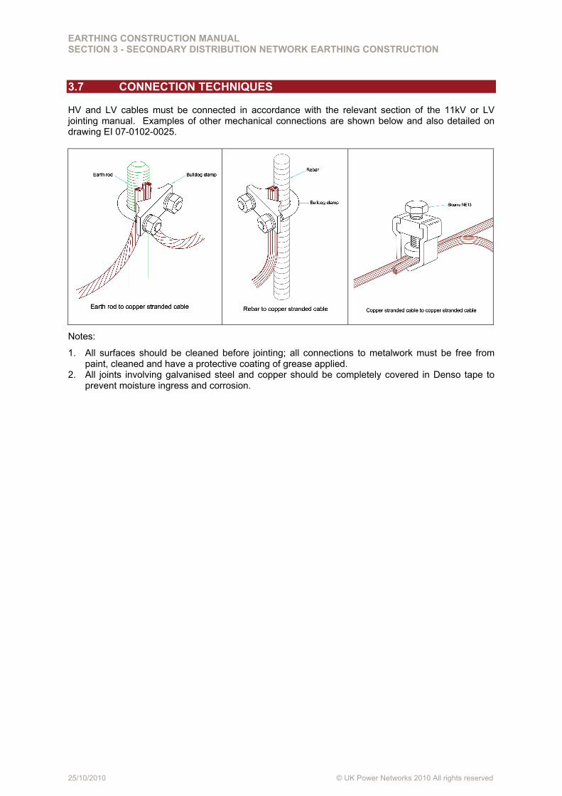
3.7 CONNECTION TECHNIQUES
HV and LV cables must be connected in accordance with the relevant section of the 11kV or LV jointing manual. Examples of other mechanical connections are shown below and also detailed on drawing EI 07-0102-0025.
Notes:
1. All surfaces should be cleaned before jointing; all connections to metalwork must be free from paint, cleaned and have a protective coating of grease applied.
2. All joints involving galvanised steel and copper should be completely covered in Denso tape to prevent moisture ingress and corrosion.
EARTHING CONSTRUCTION MANUAL SECTION 3 - SECONDARY DISTRIBUTION NETWORK EARTHING CONSTRUCTION
25/10/2010 © UK Power Networks 2010 All rights reserved
3.8 MEASUREMENTS
Reserved for future use - refer to the measurements section of the earthing construction manual and use existing practices.
EARTHING CONSTRUCTION MANUAL SECTION 3 - SECONDARY DISTRIBUTION NETWORK EARTHING CONSTRUCTION
25/10/2010 © UK Power Networks 2010 All rights reserved
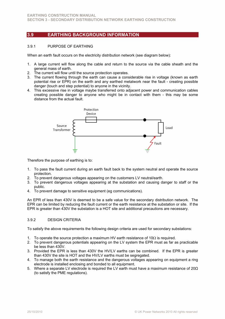
3.9 EARTHING BACKGROUND INFORMATION
3.9.1 PURPOSE OF EARTHING
When an earth fault occurs on the electricity distribution network (see diagram below):
1. A large current will flow along the cable and return to the source via the cable sheath and the general mass of earth.
2. The current will flow until the source protection operates. 3. The current flowing through the earth can cause a considerable rise in voltage (known as earth
potential rise or EPR) on the earth and any earthed metalwork near the fault - creating possible danger (touch and step potential) to anyone in the vicinity.
4. This excessive rise in voltage maybe transferred onto adjacent power and communication cables creating possible danger to anyone who might be in contact with them - this may be some distance from the actual fault.
Protection Device
Load
Fault
Source Transformer
Therefore the purpose of earthing is to:
1. To pass the fault current during an earth fault back to the system neutral and operate the source protection.
2. To prevent dangerous voltages appearing on the customers LV neutral/earth. 3. To prevent dangerous voltages appearing at the substation and causing danger to staff or the
public. 4. To prevent damage to sensitive equipment (eg communications).
An EPR of less than 430V is deemed to be a safe value for the secondary distribution network. The EPR can be limited by reducing the fault current or the earth resistance at the substation or site. If the EPR is greater than 430V the substation is a HOT site and additional precautions are necessary.
3.9.2 DESIGN CRITERIA
To satisfy the above requirements the following design criteria are used for secondary substations:
1. To operate the source protection a maximum HV earth resistance of 10 is required. 2. To prevent dangerous potentials appearing on the LV system the EPR must as far as practicable
be less than 430V. 3. Provided the EPR is less than 430V the HV/LV earths can be combined. If the EPR is greater
than 430V the site is HOT and the HV/LV earths must be segregated. 4. To manage both the earth resistance and the dangerous voltages appearing on equipment a ring
electrode is installed enclosing and bonded to all equipment. 5. Where a separate LV electrode is required the LV earth must have a maximum resistance of 20Ω
(to satisfy the PME regulations).
EARTHING CONSTRUCTION MANUAL SECTION 3 - SECONDARY DISTRIBUTION NETWORK EARTHING CONSTRUCTION
25/10/2010 © UK Power Networks 2010 All rights reserved
3.10 DEFINITIONS
This section defines some of the terms used in this guide. Further details can be found in Section 1 and 2 of the earthing manual.
Earth Potential Rise (EPR)
EPR is the potential (or voltage) rise that occurs on any metalwork due to the current that flows through the ground when an earth fault occurs on the HV or LV network. Note - some current will flow through the cable sheath back to the source and some will flow through the ground, it is only the current that flows through the ground that causes the earth potential rise.
Installing a buried grading electrode around the site and equipment and bonding exposed metalwork together helps to reduce potential differences between a person's hands and feet such that any current flowing through the body is kept to a safe level.
Touch Potential
The touch potential is the potential difference between a person’s hands and feet when standing up to 1m away from any earthed metalwork they are touching.
Step Potential
The step potential is the potential difference between a person’s feet assumed to be 1m apart.
EPR Database
The EPR database (Intranet > Applications > Reporting Centre) is UK Power Networks' database of grid and primary substations with details of the EPR, whether the site is hot or cold, and other relevant earthing information.
Cold Site
A cold site is a primary or secondary substation where the EPR is less than 430V.
Hot Site
A hot site is a primary or secondary substation where the EPR is greater than 430V. At a hot secondary site the HV and LV earths must be segregated so that the potential on the HV earth during an earth fault is not transferred to the customer's LV earth terminal.
Combined Neutral Earth (CNE) Cable
A CNE cable has a combined neutral and earth metallic outer sheath with a PVC covering and is used in a PME (protective multiple earthing) LV earthing system; in BS 7671 (IEE Wiring Regulations) this is called TN-C-S. This has a combined neutral and earth up to the cutout and then a separate neutral and earth on the customers side.
Separate Neutral Earth (SNE) Cable
An SNE cable has separate neutral and earth conductors. Generally the neutral conductor is a fourth core and the earth conductor forms a protective sheath. This cable is generally used in a TN-S (separate neutral and earth) LV earthing system.