
Earth-Rite II FIBC - Newson Gale · Earth-Rite® II FIBC ... This label is fitted behind the window...
16
Earth ® -Rite II FIBC Static Grounding System For Flexible Intermediate Bulk Containers (Type “C” Bags) For use on 110-120 Volt and 220-240 Volt AC Supplies Installation & Operating Instructions READ MANUAL BEFORE COMMENCING WITH INSTALLATION Model: ERII - June 13 II 2 (1) GD The safety of any system incorporating the equipment referred to in this manual is the responsibility of the installer of the system. If the equipment is used in a manner not specified by the manufacturer, the protection provided by the equipment may be impaired. Any warranty is made void if the equipment is not installed, or used, in accordance with the manufacturers instructions. www.newson-gale.co.uk EN ATEX / IECEx
Transcript of Earth-Rite II FIBC - Newson Gale · Earth-Rite® II FIBC ... This label is fitted behind the window...

#
Earth ®-Rite II FIBC Static Grounding System
For Flexible Intermediate Bulk Containers (Type “C” Bags)
For use on 110-120 Volt and 220-240 Volt AC Supplies
Installation & Operating Instructions
READ MANUALBEFORE COMMENCINGWITH INSTALLATION
Model: ERII - June 13
II 2 (1) GD
The safety of any system incorporating the equipment referred to in this manual is the responsibility of the installer of the system. If the equipment is used in a manner not specified by the manufacturer, the protection provided by the equipment may be impaired. Any warranty is made void if the equipment is not installed, or used, in accordance with the manufacturers instructions.
www.newson-gale.co.uk
EN
ATEX / IECEx

2 3
Earth-Rite II FIBCStatic Earth Monitoring System
System using an Exd IIC Control Unit
The Earth-Rite II FIBC system is intended for use with Type “C” FIBC Bags. It is set to show permissive only when the system detects that the connection to the Type “C” FIBC Bag, and to
8earth, is less than 10 Ohms* nominal resistance. Until this condition is achieved, the system remains non-permissive.
7* For systems using FIBC’s manufactured to the 10 Ohms 7 standard, the healthy Loop Resistance needs to be < 10 Ohms.
Installation
The installation shall be carried out by suitably trained personnel in accordance with the relevant sections of IEC 60079 and EN 60079.
All cables entering the monitoring unit must be connected through approved cable glands in accordance with EN 60079-14.
The glands should be fitted in such a way as to maintain the ingress protection rating of the enclosure.
Unused entries must be fitted with approved stopper plugs.
The system should be connected as per the enclosed installation drawings.
The Earth-Rite II system should be powered from 110-120 Volts or 220-240 Volts 50Hz.
The system should be protected using a 2A fast blow fuse mounted in the distribution board / fuse box.
The monitoring unit should be mounted, with the indicator window facing away from direct sunlight, at a convenient location, visible to the operator.
The lid of the Monitoring Unit enclosure is removed by rotating it in an anti-clockwise direction. A pair of tools, which locate in the two holes in the lid, are provided to assist in this operation.
After installation of wiring, secure the cover to the body making sure it is fully tightened.
Note: It is recommended that the transfer operation is interlocked with the contacts of the Earth-Rite II unit. This will ensure that the operation is stopped if the earth connection is inadvertently lost.
Maintenance: Periodically check exterior of enclosure for damage or deterioration.
Other Approvals
Functional Safety
The Earth-Rite II has been given a SIL (Safety Integrity Level) rating of 2.
IF YOU HAVE ANY QUERIES REGARDING THE ABOVE POINTS THEN PLEASE CONTACT NEWSON GALE, OR THEIR APPROVED DISTRIBUTOR, WITHOUT DELAY.
Certification Label Detail
This label is fitted behind the window of the Earth-Rite II Exd enclosure
Newson Gale LtdNottingham NG4 2JX UK
Sira 09ATEX2047
II 2 (1) GD0518
DO NOT OPEN WHEN AN EXPLOSIVE GASAND/OR DUST ATMOSPHERE MAY BE PRESENT
Earth-Rite II
Um = 250V ac or dc
Model Number mmmmm
Serial Number
Control Drg.: CCCCC
: YY/XXXXX
Ex d[ia] IIC T6 Gb(Ga)Ex tb IIIC T80°C IP66 Db
Ta = -40°C to +55°CIECEx SIR 09.0018
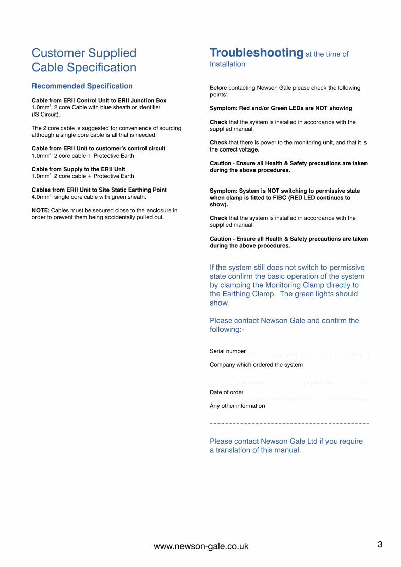
Customer SuppliedCable Specification
Recommended Specification
Cable from ERII Control Unit to ERII Junction Box21.0mm 2 core Cable with blue sheath or identifier
(IS Circuit).
The 2 core cable is suggested for convenience of sourcing although a single core cable is all that is needed.
Cable from ERII Unit to customer’s control circuit21.0mm 2 core cable + Protective Earth
Cable from Supply to the ERII Unit21.0mm 2 core cable + Protective Earth
Cables from ERII Unit to Site Static Earthing Point 24.0mm single core cable with green sheath.
NOTE: Cables must be secured close to the enclosure in order to prevent them being accidentally pulled out.
Troubleshooting at the time of
Installation
Before contacting Newson Gale please check the following points:-
Symptom: Red and/or Green LEDs are NOT showing
Check that the system is installed in accordance with the supplied manual.
Check that there is power to the monitoring unit, and that it is the correct voltage.
Caution - Ensure all Health & Safety precautions are taken during the above procedures.
Symptom: System is NOT switching to permissive state when clamp is fitted to FIBC (RED LED continues to show).
Check that the system is installed in accordance with the supplied manual.
Caution - Ensure all Health & Safety precautions are taken during the above procedures.
If the system still does not switch to permissive state confirm the basic operation of the system by clamping the Monitoring Clamp directly to the Earthing Clamp. The green lights should show.
Please contact Newson Gale and confirm the following:-
Serial number
Company which ordered the system
Date of order
Any other information
Please contact Newson Gale Ltd if you require a translation of this manual.
www.newson-gale.co.ukwww.newson-gale.co.uk
2 3
Earth-Rite II FIBCStatic Earth Monitoring System
System using an Exd IIC Control Unit
The Earth-Rite II FIBC system is intended for use with Type “C” FIBC Bags. It is set to show permissive only when the system detects that the connection to the Type “C” FIBC Bag, and to
8earth, is less than 10 Ohms* nominal resistance. Until this condition is achieved, the system remains non-permissive.
7* For systems using FIBC’s manufactured to the 10 Ohms 7 standard, the healthy Loop Resistance needs to be < 10 Ohms.
Installation
The installation shall be carried out by suitably trained personnel in accordance with the relevant sections of IEC 60079 and EN 60079.
All cables entering the monitoring unit must be connected through approved cable glands in accordance with EN 60079-14.
The glands should be fitted in such a way as to maintain the ingress protection rating of the enclosure.
Unused entries must be fitted with approved stopper plugs.
The system should be connected as per the enclosed installation drawings.
The Earth-Rite II system should be powered from 110-120 Volts or 220-240 Volts 50Hz.
The system should be protected using a 2A fast blow fuse mounted in the distribution board / fuse box.
The monitoring unit should be mounted, with the indicator window facing away from direct sunlight, at a convenient location, visible to the operator.
The lid of the Monitoring Unit enclosure is removed by rotating it in an anti-clockwise direction. A pair of tools, which locate in the two holes in the lid, are provided to assist in this operation.
After installation of wiring, secure the cover to the body making sure it is fully tightened.
Note: It is recommended that the transfer operation is interlocked with the contacts of the Earth-Rite II unit. This will ensure that the operation is stopped if the earth connection is inadvertently lost.
Maintenance: Periodically check exterior of enclosure for damage or deterioration.
Other Approvals
Functional Safety
The Earth-Rite II has been given a SIL (Safety Integrity Level) rating of 2.
IF YOU HAVE ANY QUERIES REGARDING THE ABOVE POINTS THEN PLEASE CONTACT NEWSON GALE, OR THEIR APPROVED DISTRIBUTOR, WITHOUT DELAY.
Certification Label Detail
This label is fitted behind the window of the Earth-Rite II Exd enclosure
Newson Gale LtdNottingham NG4 2JX UK
Sira 09ATEX2047
II 2 (1) GD0518
DO NOT OPEN WHEN AN EXPLOSIVE GASAND/OR DUST ATMOSPHERE MAY BE PRESENT
Earth-Rite II
Um = 250V ac or dc
Model Number mmmmm
Serial Number
Control Drg.: CCCCC
: YY/XXXXX
Ex d[ia] IIC T6 Gb(Ga)Ex tb IIIC T80°C IP66 Db
Ta = -40°C to +55°CIECEx SIR 09.0018
Customer SuppliedCable Specification
Recommended Specification
Cable from ERII Control Unit to ERII Junction Box21.0mm 2 core Cable with blue sheath or identifier
(IS Circuit).
The 2 core cable is suggested for convenience of sourcing although a single core cable is all that is needed.
Cable from ERII Unit to customer’s control circuit21.0mm 2 core cable + Protective Earth
Cable from Supply to the ERII Unit21.0mm 2 core cable + Protective Earth
Cables from ERII Unit to Site Static Earthing Point 24.0mm single core cable with green sheath.
NOTE: Cables must be secured close to the enclosure in order to prevent them being accidentally pulled out.
Troubleshooting at the time of
Installation
Before contacting Newson Gale please check the following points:-
Symptom: Red and/or Green LEDs are NOT showing
Check that the system is installed in accordance with the supplied manual.
Check that there is power to the monitoring unit, and that it is the correct voltage.
Caution - Ensure all Health & Safety precautions are taken during the above procedures.
Symptom: System is NOT switching to permissive state when clamp is fitted to FIBC (RED LED continues to show).
Check that the system is installed in accordance with the supplied manual.
Caution - Ensure all Health & Safety precautions are taken during the above procedures.
If the system still does not switch to permissive state confirm the basic operation of the system by clamping the Monitoring Clamp directly to the Earthing Clamp. The green lights should show.
Please contact Newson Gale and confirm the following:-
Serial number
Company which ordered the system
Date of order
Any other information
Please contact Newson Gale Ltd if you require a translation of this manual.
www.newson-gale.co.ukwww.newson-gale.co.uk

4 5
nc
2
PL3
PL2
1
+vPL1
PL4
PL1
PL2 PL3
no no ncc c
0vsw
N120V L2240V
G1
C1
C2
G2
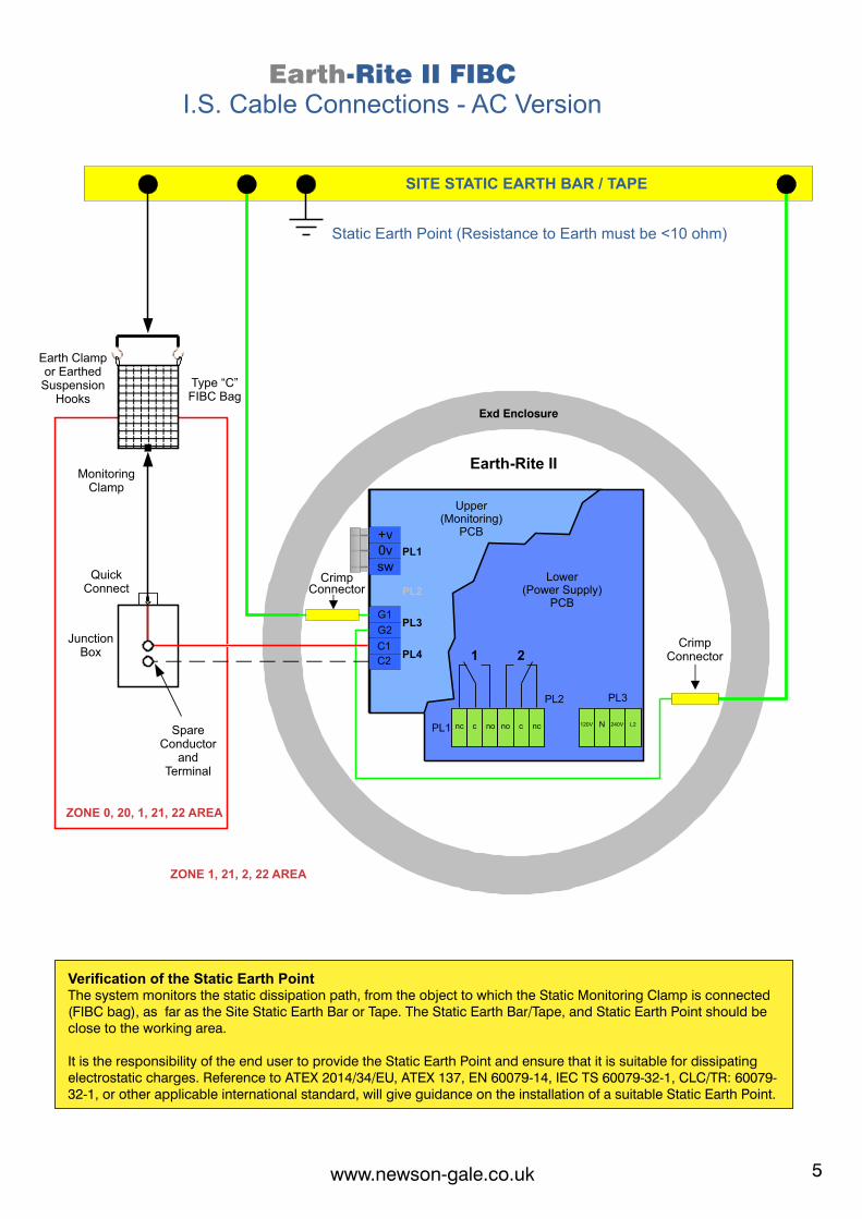
ZONE 0, 20, 1, 21, 22 AREA
ZONE 1, 21, 2, 22 AREA
Upper (Monitoring)
PCB
Lower(Power Supply)
PCB
Earth Clampor Earthed
Suspension Hooks
Type “C” FIBC Bag
Earth-Rite II
Exd Enclosure
Spare Conductor
andTerminal
QuickConnect
MonitoringClamp
CrimpConnector
CrimpConnector
JunctionBox
SITE STATIC EARTH BAR / TAPE
Static Earth Point (Resistance to Earth must be <10 ohm)
Earth-Rite II FIBCI.S. Cable Connections - AC Version
www.newson-gale.co.ukwww.newson-gale.co.uk
-RITE II SYSTEMEARTHComponent Identification
AC POWER SUPPLY PCBVAC - FORM INSULATING COVERMONITORING PCB
Avoiding Electrostatic Discharge (ESD) damage to the ERII monitoring PCB /Card
Always take precautions to ensure that you are not electrostatically charged whilst handling the monitoring PCB / Card.
Always handle the PCB / Card by the edges, or terminal block, and avoid touching the components.
When not fitted inside the ERII enclosure, always keep the PCB / Card in the static dissipative bag provided.
Internal Component Assembly
Always observe precautions against damage to the PCB’s from electrostatic discharge.
1. Remove the lid of the enclosure and remove the blue approval label. This can be achieved by unscrewing the left-hand screws 4 revolutions anti-clockwise and removing the right-hand screw completely.
2. Disconnect the three wires of the ribbon cable from the terminal block.Remove the monitoring PCB by unscrewing the three hexagonal metal pillars. Place the PCB in the anti-static bag provided and keep it safe.
3. Remove the vac-form insulating cover.
4. Install the various cables into the enclosure using suitable glands and/or conduit. Make the connections to the Power Supply PCB.
5. Replace the vac-form insulating cover.
6. Replace the monitoring PCB and secure using the three hexagonal metal pillars. Reconnect the ribbon cable and make the external I.S. wiring connections into the Terminal block.
7. Replace the blue approval label and secure using the screws provided. Replace the lid of the enclosure securely.
Verification of the Static Earth PointThe system monitors the static dissipation path, from the object to which the Static Monitoring Clamp is connected (FIBC bag), as far as the Site Static Earth Bar or Tape. The Static Earth Bar/Tape, and Static Earth Point should be close to the working area.
It is the responsibility of the end user to provide the Static Earth Point and ensure that it is suitable for dissipating electrostatic charges. Reference to ATEX 2014/34/EU, ATEX 137, EN 60079-14, IEC TS 60079-32-1, CLC/TR: 60079-32-1, or other applicable international standard, will give guidance on the installation of a suitable Static Earth Point.
4 5
nc
2
PL3
PL2
1
+vPL1
PL4
PL1
PL2 PL3
no no ncc c
0vsw
N120V L2240V
G1
C1
C2
G2
ZONE 0, 20, 1, 21, 22 AREA
ZONE 1, 21, 2, 22 AREA
Upper (Monitoring)
PCB
Lower(Power Supply)
PCB
Earth Clampor Earthed
Suspension Hooks
Type “C” FIBC Bag
Earth-Rite II
Exd Enclosure
Spare Conductor
andTerminal
QuickConnect
MonitoringClamp
CrimpConnector
CrimpConnector
JunctionBox
SITE STATIC EARTH BAR / TAPE
Static Earth Point (Resistance to Earth must be <10 ohm)
Earth-Rite II FIBCI.S. Cable Connections - AC Version
www.newson-gale.co.ukwww.newson-gale.co.uk
-RITE II SYSTEMEARTHComponent Identification
AC POWER SUPPLY PCBVAC - FORM INSULATING COVERMONITORING PCB
Avoiding Electrostatic Discharge (ESD) damage to the ERII monitoring PCB /Card
Always take precautions to ensure that you are not electrostatically charged whilst handling the monitoring PCB / Card.
Always handle the PCB / Card by the edges, or terminal block, and avoid touching the components.
When not fitted inside the ERII enclosure, always keep the PCB / Card in the static dissipative bag provided.
Internal Component Assembly
Always observe precautions against damage to the PCB’s from electrostatic discharge.
1. Remove the lid of the enclosure and remove the blue approval label. This can be achieved by unscrewing the left-hand screws 4 revolutions anti-clockwise and removing the right-hand screw completely.
2. Disconnect the three wires of the ribbon cable from the terminal block.Remove the monitoring PCB by unscrewing the three hexagonal metal pillars. Place the PCB in the anti-static bag provided and keep it safe.
3. Remove the vac-form insulating cover.
4. Install the various cables into the enclosure using suitable glands and/or conduit. Make the connections to the Power Supply PCB.
5. Replace the vac-form insulating cover.
6. Replace the monitoring PCB and secure using the three hexagonal metal pillars. Reconnect the ribbon cable and make the external I.S. wiring connections into the Terminal block.
7. Replace the blue approval label and secure using the screws provided. Replace the lid of the enclosure securely.
Verification of the Static Earth PointThe system monitors the static dissipation path, from the object to which the Static Monitoring Clamp is connected (FIBC bag), as far as the Site Static Earth Bar or Tape. The Static Earth Bar/Tape, and Static Earth Point should be close to the working area.
It is the responsibility of the end user to provide the Static Earth Point and ensure that it is suitable for dissipating electrostatic charges. Reference to ATEX 2014/34/EU, ATEX 137, EN 60079-14, IEC TS 60079-32-1, CLC/TR: 60079-32-1, or other applicable international standard, will give guidance on the installation of a suitable Static Earth Point.

6 7
nc
1 2
2
PL3
PL2
1
+vPL1
PL4
PL1
PL2 PL3
no no ncc c
G1
C1
0vsw
N120V L2
G2
C2
L N
240V
Earth-Rite II FIBC
Non - I.S. Cable Connections - AC Version220-240V 50/60Hz Live and Neutral Supply
ZONE 1, 21, 2, 22 AREA
nc
1 2
2
PL3
PL2
1
+vPL1
PL4
PL1
PL2 PL3
no no ncc c
G1
C1
0vsw
N120V L2
G2
C2
LN
240V
Upper (Monitoring)
PCB
Lower(Power Supply)
PCB
Pillar forProtective Earth(PE) Conductor
Protective Earth(PE) Conductor
Earth-Rite II
Exd Enclosure
Non-Intrinsically Safe Wiring
CustomerInterlockCircuits
220-240V 50/60HzSupply
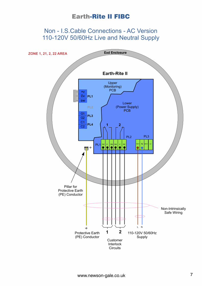
Earth-Rite II FIBC
Non - I.S.Cable Connections - AC Version110-120V 50/60Hz Live and Neutral Supply
ZONE 1, 21, 2, 22 AREA
Upper (Monitoring)
PCB
Lower(Power Supply)
PCB
Pillar forProtective Earth(PE) Conductor
Protective Earth(PE) Conductor
Earth-Rite II
Exd Enclosure
Non-Intrinsically Safe Wiring
CustomerInterlockCircuits
110-120V 50/60HzSupply
www.newson-gale.co.ukwww.newson-gale.co.uk
6 7
nc
1 2
2
PL3
PL2
1
+vPL1
PL4
PL1
PL2 PL3
no no ncc c
G1
C1
0vsw
N120V L2
G2
C2
L N
240V
Earth-Rite II FIBC
Non - I.S. Cable Connections - AC Version220-240V 50/60Hz Live and Neutral Supply
ZONE 1, 21, 2, 22 AREA
nc
1 2
2
PL3
PL2
1
+vPL1
PL4
PL1
PL2 PL3
no no ncc c
G1
C1
0vsw
N120V L2
G2
C2
LN
240V
Upper (Monitoring)
PCB
Lower(Power Supply)
PCB
Pillar forProtective Earth(PE) Conductor
Protective Earth(PE) Conductor
Earth-Rite II
Exd Enclosure
Non-Intrinsically Safe Wiring
CustomerInterlockCircuits
220-240V 50/60HzSupply
Earth-Rite II FIBC
Non - I.S.Cable Connections - AC Version110-120V 50/60Hz Live and Neutral Supply
ZONE 1, 21, 2, 22 AREA
Upper (Monitoring)
PCB
Lower(Power Supply)
PCB
Pillar forProtective Earth(PE) Conductor
Protective Earth(PE) Conductor
Earth-Rite II
Exd Enclosure
Non-Intrinsically Safe Wiring
CustomerInterlockCircuits
110-120V 50/60HzSupply
www.newson-gale.co.ukwww.newson-gale.co.uk

8 9
STATIC DISSIPATION GROUND
MONITORING CLAMP, VIA JUNCTION BOX
JUNCTION BOX SPARE TERMINAL
INTERNAL CONNECTIONS TO LOWER (PSU) PCB
Intrinsically Safe PCB Connections
Monitoring PCB
Power Supply PCB
INTERNAL CONNECTIONS TOUPPER (MONITORING) PCB
nc
21
PL4
Lower (PSU) PCB - AC
PL1
PL2
no no ncc c
+v0vsw
PL3
N120V L2240V
PL3
PL1
PL4
+v
G1
C1
0vsw
G2
C2
PL2
SPARE CONDUCTOR
Upper (Monitoring) PCB
www.newson-gale.co.ukwww.newson-gale.co.uk
Remove Lid Keys from packaging Place Lid Keys into the two ERIImetal enclosure lid holes
With Lid Keys securely located in holes,rotate clockwise to tighten the lid ontothe enclosure.
With Lid Keys securely located in holes,rotate counter-clockwise to loosen the lid from the enclosure.
Earth-Rite II Metal Enclosure Lid Keys

10 11www.newson-gale.co.ukwww.newson-gale.co.uk
Operation System using Monitoring Clamp and Lifting Gear with Grounded Hooks
Important Note: The Earthing Circuit should be fitted prior any other operation, as per the
recommendations of IEC TS 60079-32-1, CLC/TR: 60079-32-1, NFPA 77 and API RP 2003.
Operation - System using Monitoring Clamp and Supplementary Earthing Clamp
Important Note: The Clamp/s should be fitted prior to any other operation, as per the recommendations
of IEC TS 60079-32-1,CLC/TR: 60079-32-1, NFPA 77 and API RP 2003.
ERIIJunction Box
Clamp
GaleNewson
GaleNewson
ERIIJunction Box
Clamp
GaleNewson
GaleNewson
GaleNewson
GaleNewson
X
A. In the normal "rest" state, with the Monitoring Clamp
(blue cable) stowed on the insulated pin, the RedNegative Earth Condition LED will be showing.
B. Attach the Supplementary Earthing Clamp (green
cable) onto a top seam of the FIBC (bag).
C. Attach the Monitoring Clamp (blue cable) onto the FIBC
(bag) bottom earth point.
8If the connection is healthy (Loop Resistance <10 Ohms*),
the Positive Earth Condition LEDs will flash and the Green
interlock contacts will close. (This may take a few seconds).
The product transfer can now take place.
D. If the earth monitoring loop circuit is broken during the
transfer operation, the LED Red Negative Earth Condition
will show and the interlock contacts will open.
E. On completion the Monitoring Clamp should be
removed from the FIBC (bag) and stowed on the insulated
pin on the front of the junction box. The Red Negative
Earth Condition LED will show and the interlock contacts
will open. The Earthing Clamp should then be
disconnected from the FIBC (bag).
Type “C”FIBC Bag
EarthPoint
GaleNewson
GaleNewson
7* For systems using FIBC’s manufactured to the 10 ohm standard, 7 the healthy Loop Resistance needs to be < 10 ohms.
ERIIJunction Box
Clamp
GaleNewson
GaleNewson
ERIIJunction Box
Clamp
GaleNewson
GaleNewson
GaleNewson
GaleNewson
X
A. In the normal "rest" state, with the Monitoring Clamp
(blue cable) stowed on the insulated pin, the Negative RedEarth Condition LED will be showing.
B. Attach the FIBC (bag) to the lifting hooks and check that
the lifting loops are in good contact with the lifting hooks.
C. Attach the Monitoring Clamp (blue cable) onto the FIBC
(bag) bottom earth tag.
8If the connection is healthy, (Loop Resistance <10 Ohms*),
the Positive Earth Condition LEDs will flash and the Green
interlock contacts will close. (This may take a few seconds).
The product transfer can now take place.
D. If the earth monitoring loop circuit is broken during the
transfer operation, the LED Red Negative Earth Condition
will show and the interlock contacts will open.
E. On completion the Monitoring Clamp should be
removed from the FIBC (bag) and stowed on the insulated
pin on the front of the junction box. The Red Negative
Earth Condition LED will show and the interlock contacts will
open.
7* For systems using FIBC’s manufactured to the 10 ohm standard, 7 the healthy Loop Resistance needs to be < 10 ohms.
Lifting Loop
Top Seam
FIBC “C” FIBC Bag
GaleNewson
GaleNewson
Earth Point
12 13
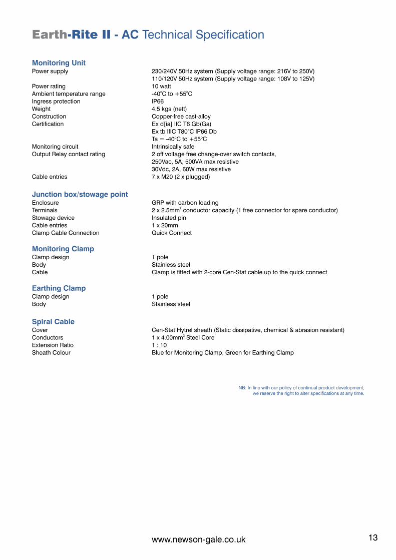
Earth-Rite II - AC Technical Specification
Monitoring UnitPower supply 230/240V 50Hz system (Supply voltage range: 216V to 250V)
110/120V 50Hz system (Supply voltage range: 108V to 125V)
Power rating 10 watto oAmbient temperature range -40 C to +55 C
Ingress protection IP66
Weight 4.5 kgs (nett)
Construction Copper-free cast-alloy
Certification Ex d[ia] IIC T6 Gb(Ga)
Ex tb IIIC T80°C IP66 Db
Ta = -40°C to +55°C
Monitoring circuit Intrinsically safe
Output Relay contact rating 2 off voltage free change-over switch contacts,
250Vac, 5A, 500VA max resistive
30Vdc, 2A, 60W max resistive
Cable entries 7 x M20 (2 x plugged)
Junction box/stowage pointEnclosure GRP with carbon loading
2Terminals 2 x 2.5mm conductor capacity (1 free connector for spare conductor)
Stowage device Insulated pin
Cable entries 1 x 20mm
Clamp Cable Connection Quick Connect
Monitoring ClampClamp design 1 pole
Body Stainless steel
Cable Clamp is fitted with 2-core Cen-Stat cable up to the quick connect
Earthing ClampClamp design 1 pole
Body Stainless steel
Spiral CableCover Cen-Stat Hytrel sheath (Static dissipative, chemical & abrasion resistant)
2Conductors 1 x 4.00mm Steel Core
Extension Ratio 1 : 10
Sheath Colour Blue for Monitoring Clamp, Green for Earthing Clamp
NB: In line with our policy of continual product development,we reserve the right to alter specifications at any time.
www.newson-gale.co.ukwww.newson-gale.co.uk
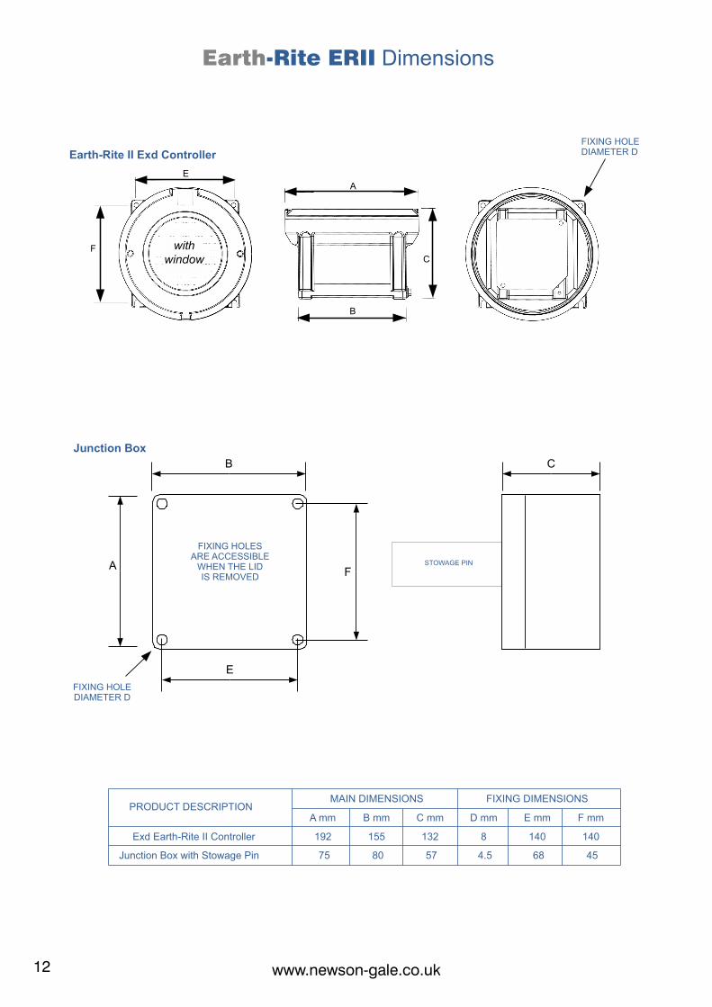
Junction Box
B
E
AF
C
FIXING HOLE DIAMETER D
STOWAGE PIN
FIXING HOLES ARE ACCESSIBLE
WHEN THE LIDIS REMOVED
A mm B mm C mm
75 80 57
PRODUCT DESCRIPTION
Junction Box with Stowage Pin
MAIN DIMENSIONS
D mm E mm F mm
4.5 68 45
FIXING DIMENSIONS
192 155 132Exd Earth-Rite II Controller 8 140 140
Earth-Rite ERII Dimensions
F
Earth-Rite II Exd Controller
C
A
E
B
FIXING HOLE DIAMETER D
with window
12 13
Earth-Rite II - AC Technical Specification
Monitoring UnitPower supply 230/240V 50Hz system (Supply voltage range: 216V to 250V)
110/120V 50Hz system (Supply voltage range: 108V to 125V)
Power rating 10 watto oAmbient temperature range -40 C to +55 C
Ingress protection IP66
Weight 4.5 kgs (nett)
Construction Copper-free cast-alloy
Certification Ex d[ia] IIC T6 Gb(Ga)
Ex tb IIIC T80°C IP66 Db
Ta = -40°C to +55°C
Monitoring circuit Intrinsically safe
Output Relay contact rating 2 off voltage free change-over switch contacts,
250Vac, 5A, 500VA max resistive
30Vdc, 2A, 60W max resistive
Cable entries 7 x M20 (2 x plugged)
Junction box/stowage pointEnclosure GRP with carbon loading
2Terminals 2 x 2.5mm conductor capacity (1 free connector for spare conductor)
Stowage device Insulated pin
Cable entries 1 x 20mm
Clamp Cable Connection Quick Connect
Monitoring ClampClamp design 1 pole
Body Stainless steel
Cable Clamp is fitted with 2-core Cen-Stat cable up to the quick connect
Earthing ClampClamp design 1 pole
Body Stainless steel
Spiral CableCover Cen-Stat Hytrel sheath (Static dissipative, chemical & abrasion resistant)
2Conductors 1 x 4.00mm Steel Core
Extension Ratio 1 : 10
Sheath Colour Blue for Monitoring Clamp, Green for Earthing Clamp
NB: In line with our policy of continual product development,we reserve the right to alter specifications at any time.
www.newson-gale.co.ukwww.newson-gale.co.uk
Junction Box
B
E
AF
C
FIXING HOLE DIAMETER D
STOWAGE PIN
FIXING HOLES ARE ACCESSIBLE
WHEN THE LIDIS REMOVED
A mm B mm C mm
75 80 57
PRODUCT DESCRIPTION
Junction Box with Stowage Pin
MAIN DIMENSIONS
D mm E mm F mm
4.5 68 45
FIXING DIMENSIONS
192 155 132Exd Earth-Rite II Controller 8 140 140
Earth-Rite ERII Dimensions
F
Earth-Rite II Exd Controller
C
A
E
B
FIXING HOLE DIAMETER D
with window
14 15
1 2
3 4
5
ERII
Junction Box
Monitoring Clamp
Site Static EarthBar / Tape
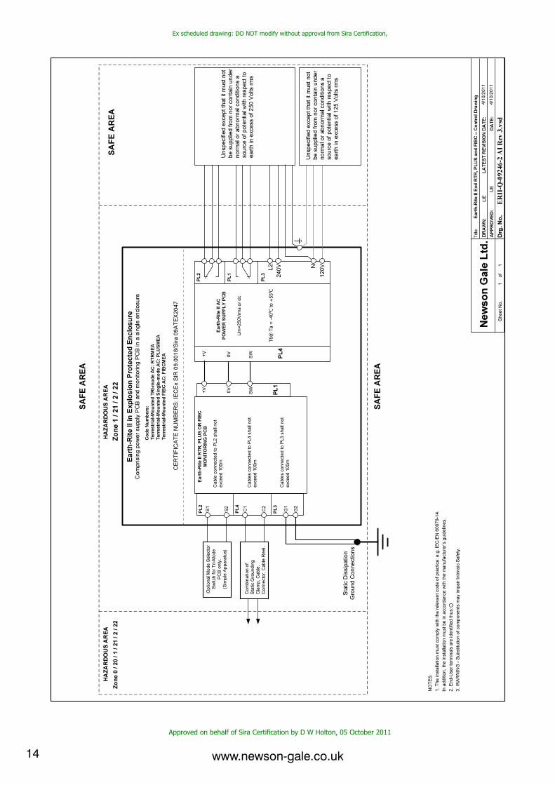
Ex scheduled
drawing:
DO NOT modify without
approval from
Sira Certification,
Approved on behalf
of
Sira
Certification by
D
W
Holton,
05
October 2011
www.newson-gale.co.ukwww.newson-gale.co.uk
Avoiding Electrostatic Discharge (ESD) damage to the ERII monitoring PCB /Card
Ÿ Always take precautions to ensure that you are not electrostatically charged whilst handling the monitoring
PCB / Card.Ÿ Always handle the PCB / Card by the edges, or terminal block, and avoid touching the components.Ÿ When not fitted inside the ERII enclosure, always keep the PCB / Card in the static dissipative bag provided.
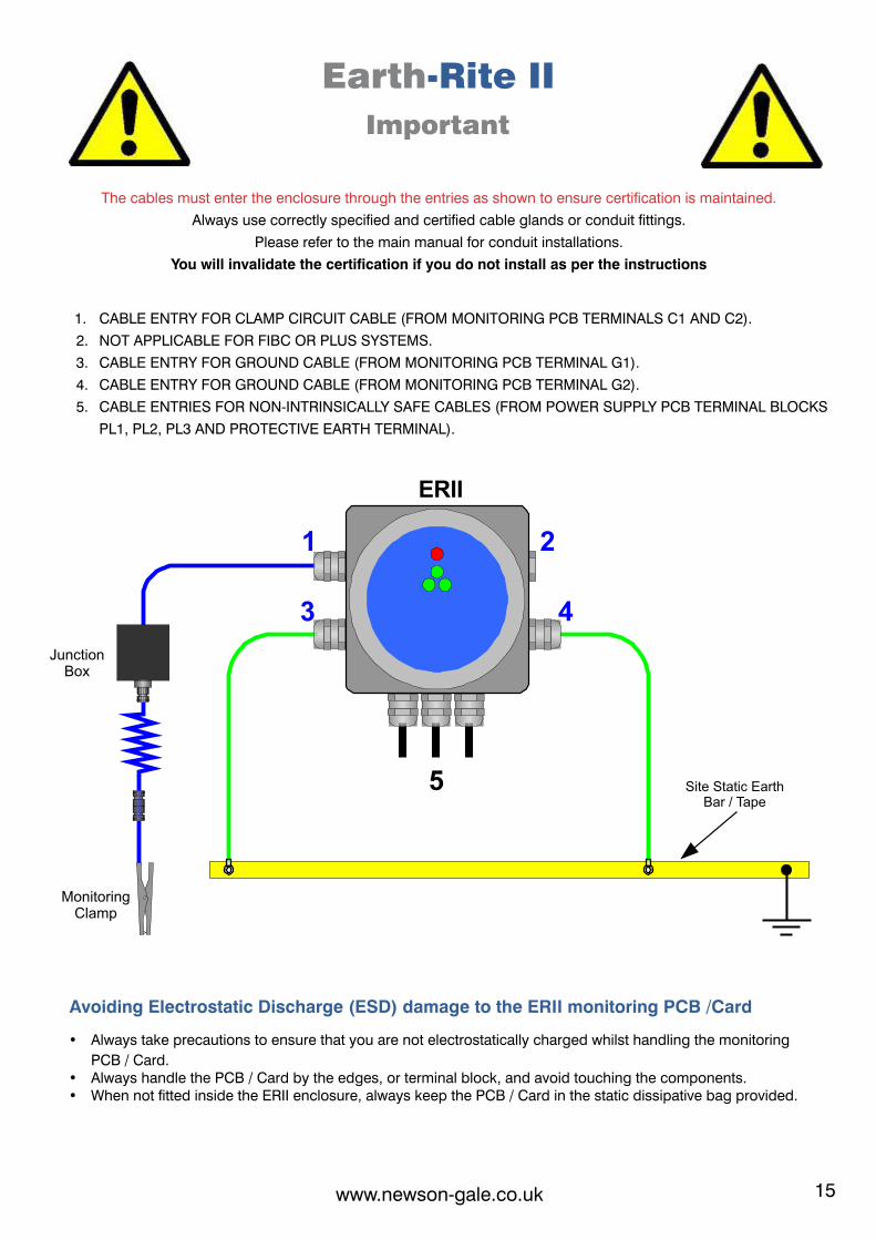
Earth-Rite II
Important
The cables must enter the enclosure through the entries as shown to ensure certification is maintained.
Always use correctly specified and certified cable glands or conduit fittings.
Please refer to the main manual for conduit installations.
You will invalidate the certification if you do not install as per the instructions
1. CABLE ENTRY FOR CLAMP CIRCUIT CABLE (FROM MONITORING PCB TERMINALS C1 AND C2).
2. NOT APPLICABLE FOR FIBC OR PLUS SYSTEMS.
3. CABLE ENTRY FOR GROUND CABLE (FROM MONITORING PCB TERMINAL G1).
4. CABLE ENTRY FOR GROUND CABLE (FROM MONITORING PCB TERMINAL G2).
5. CABLE ENTRIES FOR NON-INTRINSICALLY SAFE CABLES (FROM POWER SUPPLY PCB TERMINAL BLOCKS
PL1, PL2, PL3 AND PROTECTIVE EARTH TERMINAL).
14 15
1 2
3 4
5
ERII
Junction Box
Monitoring Clamp
Site Static EarthBar / Tape
Ex scheduled
drawing:
DO NOT modify without
approval from
Sira Certification,
Approved on behalf
of
Sira
Certification by
D
W
Holton,
05
October 2011
www.newson-gale.co.ukwww.newson-gale.co.uk
Avoiding Electrostatic Discharge (ESD) damage to the ERII monitoring PCB /Card
Ÿ Always take precautions to ensure that you are not electrostatically charged whilst handling the monitoring
PCB / Card.Ÿ Always handle the PCB / Card by the edges, or terminal block, and avoid touching the components.Ÿ When not fitted inside the ERII enclosure, always keep the PCB / Card in the static dissipative bag provided.
Earth-Rite II
Important
The cables must enter the enclosure through the entries as shown to ensure certification is maintained.
Always use correctly specified and certified cable glands or conduit fittings.
Please refer to the main manual for conduit installations.
You will invalidate the certification if you do not install as per the instructions
1. CABLE ENTRY FOR CLAMP CIRCUIT CABLE (FROM MONITORING PCB TERMINALS C1 AND C2).
2. NOT APPLICABLE FOR FIBC OR PLUS SYSTEMS.
3. CABLE ENTRY FOR GROUND CABLE (FROM MONITORING PCB TERMINAL G1).
4. CABLE ENTRY FOR GROUND CABLE (FROM MONITORING PCB TERMINAL G2).
5. CABLE ENTRIES FOR NON-INTRINSICALLY SAFE CABLES (FROM POWER SUPPLY PCB TERMINAL BLOCKS
PL1, PL2, PL3 AND PROTECTIVE EARTH TERMINAL).
16 #NG
UK
AT
EX
FIB
C E
xd A
C IS
M 2
81
11
7 R
6
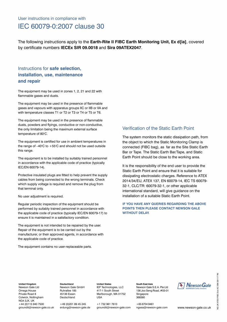
Instructions for safe selection,
installation, use, maintenance
and repair
The equipment may be used in zones 1, 2, 21 and 22 with
flammable gases and dusts.
The equipment may be used in the presence of flammable
gases and vapours with apparatus groups IIC or IIB or IIA and
with temperature classes T1 or T2 or T3 or T4 or T5 or T6.
The equipment may be used in the presence of flammable
dusts, powders and flyings, conductive or non-conductive,
the only limitation being the maximum external surface otemperature of 80 C.
The equipment is certified for use in ambient temperatures in o othe range of –40 C to +55 C and should not be used outside
this range.
The equipment is to be installed by suitably trained personnel
in accordance with the applicable code of practice (typically
IEC/EN 60079-14).
Protective insulated plugs are fitted to help prevent the supply
cables from being connected to the wrong terminals. Check
which supply voltage is required and remove the plug from
that terminal only.
No user adjustment is required.
Regular periodic inspection of the equipment should be
performed by suitably trained personnel in accordance with
the applicable code of practice (typically IEC/EN 60079-17) to
ensure it is maintained in a satisfactory condition.
The equipment is not intended to be repaired by the user.
Repair of the equipment is to be carried out by the
manufacturer, or their approved agents, in accordance with
the applicable code of practice.
The equipment contains no user-replaceable parts.
Verification of the Static Earth Point
The system monitors the static dissipation path, from
the object to which the Static Monitoring Clamp is
connected (FIBC bag), as far as the Site Static Earth
Bar or Tape. The Static Earth Bar/Tape, and Static
Earth Point should be close to the working area.
It is the responsibility of the end user to provide the
Static Earth Point and ensure that it is suitable for
dissipating electrostatic charges. Reference to ATEX
2014/34/EU, ATEX 137, EN 60079-14, IEC TS 60079-
32-1, CLC/TR: 60079-32-1, or other applicable
international standard, will give guidance on the
installation of a suitable Static Earth Point.
IF YOU HAVE ANY QUERIES REGARDING THE ABOVE
POINTS THEN PLEASE CONTACT NEWSON GALE
WITHOUT DELAY.
User instructions in compliance with
IEC 60079-0:2007 clause 30
The following instructions apply to the Earth-Rite II FIBC Earth Monitoring Unit, Ex d[ia], covered
by certificate numbers IECEx SIR 09.0018 and Sira 09ATEX2047.
www.newson-gale.co.uk
United Kingdom
Newson Gale Ltd
Omega House
Private Road 8
Colwick, Nottingham
NG4 2JX, UK
+44 (0)115 940 7500
Deutschland
Newson Gale GmbH
Ruhrallee 185
45136 Essen
Deutschland
+49 (0)201 89 45 245
South East Asia
Newson Gale S.E.A. Pte Ltd
136 Joo Seng Road, #03-01
Singapore
368360
+65 6704 9461
United States
IEP Technologies, LLC
417-1 South Street
Marlborough, MA 01752
USA
+1 732 961 7610


![THE LOCKHEED LOUNGE BY MARC NEWSON [CATALOGUE]](https://static.fdocuments.us/doc/165x107/579053de1a28ab900c8e128a/the-lockheed-lounge-by-marc-newson-catalogue.jpg)

