Earth Fault Relay - penbro.co.zapenbro.co.za/strike-technologies/strike-pdfs/ADIT-E Brochure...
2
The ADIT is an adjustable current and time earth fault relay, used in the following areas: transformers, motors, line - gear. feeders and switch Key Features: • Manufactured and supported in South Africa • Protection of high and low voltage systems • Fully electronic - H.V systems • Requires auxiliary power supply - Transformer protection • Easy to use - Motor protection • High impact plastic enclosure - Dropped overhead line protection • LED status indicator - Neutral compensator restricted earth fault protection • ADIT suitable for panel door mounting - L.V systems • Low and high voltage applications - Switchgear incomer circuit protection • Independent time and current settings - High current sub-feeder protection • Normally open and normally closed contacts - Protection of large motors • Same settings for 1A and 5A CT’s - Protection of rising mains • Sensitivity - 25mA to 2000mA Functions: • Current settings: - 1 Amp CT - 2.5 to 200% - 5 Amp CT - 0.5 to 40% • Time settings: - 1 Amp unit - 0.25 to 2.5 seconds ADIT - 5 Amp unit - 0.25 to 2.5 seconds Earth Fault Relay System Applications:
Transcript of Earth Fault Relay - penbro.co.zapenbro.co.za/strike-technologies/strike-pdfs/ADIT-E Brochure...
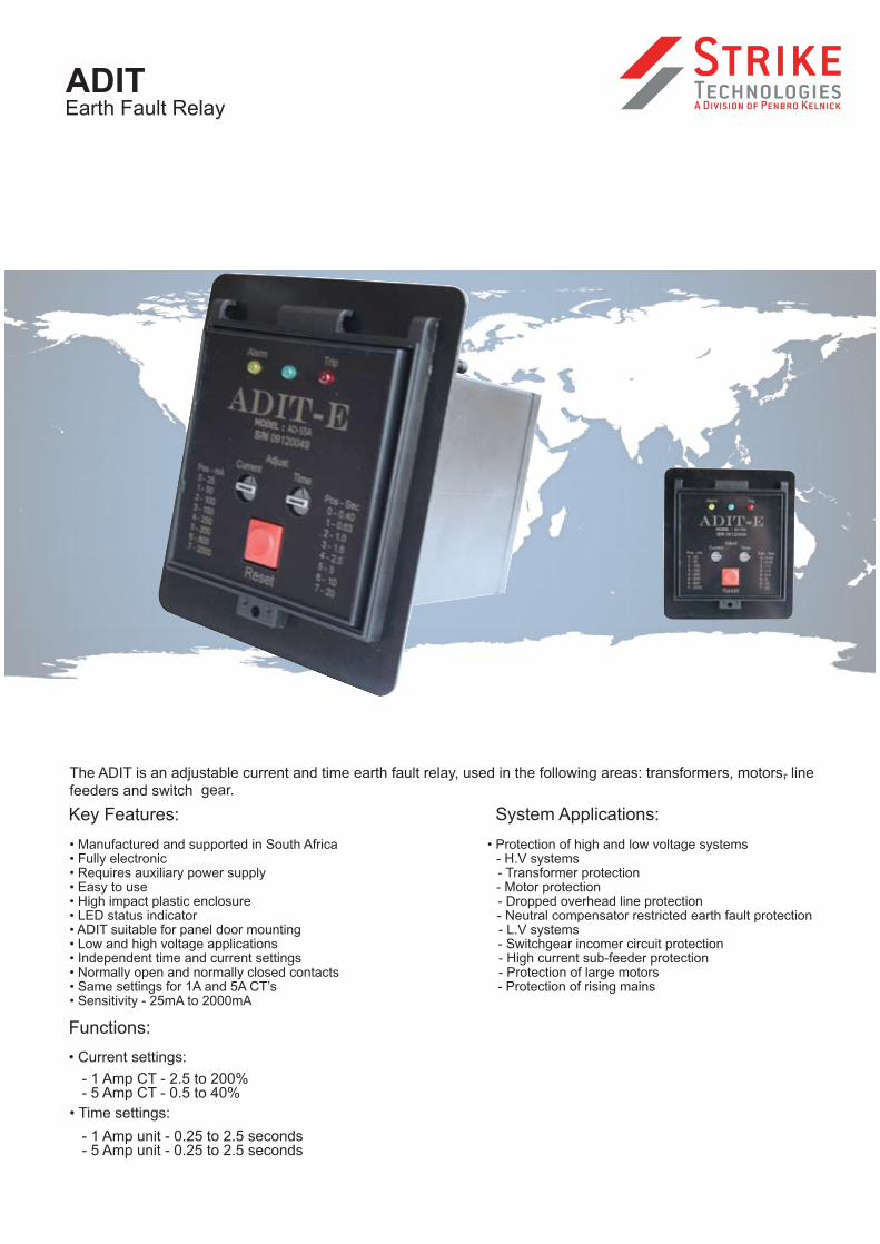
The ADIT is an adjustable current and time earth fault relay, used in the following areas: transformers, motors, line -
gear.feeders and switch
Key Features:
• Manufactured and supported in South Africa • Protection of high and low voltage systems• Fully electronic - H.V systems• Requires auxiliary power supply - Transformer protection• Easy to use - Motor protection• High impact plastic enclosure - Dropped overhead line protection• LED status indicator - Neutral compensator restricted earth fault protection• ADIT suitable for panel door mounting - L.V systems• Low and high voltage applications - Switchgear incomer circuit protection• Independent time and current settings - High current sub-feeder protection• Normally open and normally closed contacts - Protection of large motors• Same settings for 1A and 5A CT’s - Protection of rising mains• Sensitivity - 25mA to 2000mA
Functions:
• Current settings:
- 1 Amp CT - 2.5 to 200% - 5 Amp CT - 0.5 to 40%
• Time settings:
- 1 Amp unit - 0.25 to 2.5 seconds
ADIT
- 5 Amp unit - 0.25 to 2.5 seconds
Earth Fault Relay
System Applications:

MILLI-AMP THRESHOLD SETTINGS
Table of settings for switch position:
* Note position 8 & 9 are not used, but will select settings as indicated.
CURRENT TIME
Switch position
Milli-amp sensitivity
Switch position
Definite time in seconds
0 25 0 0.40 1 50 1 0.63 2 100 2 1.00 3 150 3 1.60 4 250 4 2.50 5 300 5 5.00 6 800 6 10.00 7 2000 7 20.00
* 8 25 * 8 0.40 * 9 50 * 9 0.63
PERCENTAGE OF CT SECONDARY
Table of percentage settings for 1A & 5A CT:
This table is to assist the users of the superseded electro-mechanical ADIT.
ADIT-E mA setting %In [1A CT] %In [5A CT]
25 2.5 0.5 50 5 1 100 10 2 150 15 3 250 25 5 300 30 6 800 80 16
2000 200 40
SPECIFICATIONS
• Operating conditions:
• Trip accuracy:
• Auxiliary supply.
- Model AD-55A:
- Model AD-12A:
• Relay outputs:
- Contact load -
- Contactor coil operation.AC15
- Solenoid operation.DC13
• LED trip indication will continue for approximately 8hrs
after auxiliary power failure. Note relays will be
de-energised during this period. With auxiliary power
off for 8hrs, the full backup time will only be available
when powered for approximately 3hrs.
Earth leakageTrip coilCurrent transformer
L1
BreakerL2
Customers
L3
control
Auxiliary power
station
supply method AAuxiliary powersupply method B
Method of auxiliary supplyconnection will affect the ADIT-E
indication and trip condition.
Circuit shown when theADIT-E relay output is usedto energise the customers
control-station trip coilcircuit.
The auxiliary powerconnection will depend on
the model and system voltageavailable.
1
2
3
4
7
9
8
10
K1 N/O
5
K2 N/C Auxiliarysupply
Common
?
?
oror
Contact form
Load
= 1 x N/O & 1 x N/C Ф @ 1).= 5A 550V AC (cos
= 5A 48V DC (L/R = 0ms).
= 2A 60V DC, 50ms.
220VAC and 380-550VAC ± 20%.
110VAC/DC - 220VAC/DC ± 20%.
± 20% @ 25mA &
0 – 70 Deg C Ambient.
= 1.5A 480V AC.
± 10% @ >50mA