
Early Aviation History - 1909
184
All about Mechanical Flight, THE MANUAL UC-NRLF COMPILED -BY- THE STAFF OF ISO SPECIAL- ILLUSTRATIONS
-
Upload
beatrice-rescazzi -
Category
Documents
-
view
101 -
download
16
description
History of the aviation. Pre-flight machines and airplanes. Illustrated book.
Transcript of Early Aviation History - 1909
All about Mechanical Flight,
THE
MANUALUC-NRLF
COMPILED -BY-THE STAFF OF
ISO SPECIAL- ILLUSTRATIONS


EVERYTHING AVIATION"AEROLITE
PETROL MOTOR, B.H.P.
The"ARIEL "MOTOR
(Reversing).Highest-class workman-ship. Greatest possible
power for weight. Alu-minium base. Total
weight, 6 ozs. Takesi ampere at 4 volts.
Price - 17s. 6d.
Postage 3d.
Specially designed for driving Model
Aeroplanes, Racing Boats, etc.
ll in. bore, if in. stroke.
WEIGHT 8 Ibs. 1 oz.
PISTON Domed top with 2 rings.
CONNECTING ROD PhosphorBronze.
CRANKS Ubas steel, i in. diam.
BEARINGS Phosphor Bronze, I in.
diam.x 1 in. and 5 in. diam.x i in. long.
CRANK CASE Aluminium Alloy.
WATER JACKET Copper welded tocast - iron cylinder by specialprocess.
FLY- WHEEL 4f in. diam., weight33 Ibs.
DIMENSIONS Over-all, height 10 in.,width 5 in.
SPEED 2,000 revs, per min.
IGNITION Electric.
CATALOGUES POST FREE,
6ENETFINK u*.
QtEAPSIDEr.
E. H. LANCASTERM.I.A.E. & A.M.I.IM.E.
CONSULTING ENGINEER,
1, Albemarle St., Piccadilly, W.
SPECIALIST ON
Engines for Aeroplanes
Designs for Motor Vehicles&C.
Telephone:567 Gerrarcl.
Telegrams :
" Lancamoto, London.'
DROP IT!now. Just a P.C. with your address.We send our useful 100-page list.
POST FREE.
NEW "AERO "MOTORWeight, including prqaeller, under 3 ozs.This motor is self-starting, low currentconsumption, 2| amps. Powerful, Silent,Well Balanced. Size ll in. diam., 2g inchlong.
Each 7/6 Post2d.'N.Br Full particulars, see lists.
WRITE for it. ESTABLISHED 1896.

Aluminium Castings.
R. W. COAN, 219, Goswell Road, E.C.
Markham & Prance(R. G. L. Markham, M.I.Mech.E., M.I.A.E.,H. Waymouth Prance, A.I.E.E., A. M.I. A. E.),
CONSULTING MOTOR ENGINEERS(Land, Marine, and Aeronautical).
All types of Aeroplanes supplied, includingFarman, Wright, R.E. P., Bleriot and Antoinettemachines ; specified flights guaranteed, andinstruction of clients arranged for. Dirigibleballoons supplied. Kxpert advice concerningengine installations ; tests and trials super-vised ; reports made. All makes of motors,
gliders, and accessories and fittings supplied.
143 Strand,London,W.C.Telephone : 3439 Gerrard.
Telegrams:"Motoneers, London."
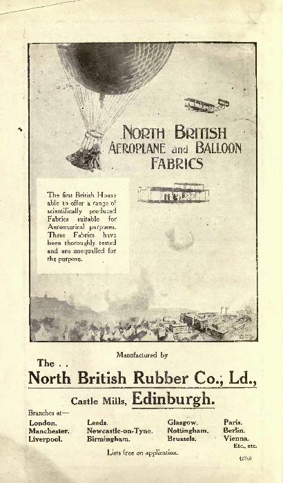
NORTH BRITISHAEROPLANE and BALLOON
FABRICS
The first British
able to offer a range of
scientifically producedFabrics suitable for
Aeronautical purposes.
These Fabrics havs
been thoroughly tested
and are unequalled for
the purpose.
Manufactured by
The . .
North British Rubber Co., Ld.,
Lists free on application.(280)

THE AERO MANUAL.
Don't
Experimentwith ignition apparatus.
There is no need. Just
order your engines fitted
with
BOSCHSpecialAeroplane
MAGNETOWrite for particulars
The Bosch Magneto Co.,
Ltd. .v 23, Store St.,
London, w.c.Telephone: Telegrams:
8610 Gerrard (2 lines)."Bomag, London.
Tightening Screws(Right and Left Threads)
ALL SIZES STOCKED.
Tubes, Rods & Castingsin all Metals.
Steel Tension Wires
H. ROLLET & CO.,12 & 13, ColdUth Square, Rose
1
cry AvenueTelephone:4674 Holbori London, E.G.
Telegrams:"Anterior, London."
Eleventh Edition.
t
jotoramial
130th Thousand.
Up-to-date and keeping abreastwith the motorcar itself.*'
The Referee.
Motor Mechanismin all its details
described in non-technical language.
pages and
200illustrations.
Every motorist should keep a copyof the
" Motor Manual " on the car.One day or olhtr it is bound to be
very useftil and save time andtemper.
''THE MOTOR" Offices,7-15, Rosebery Ave., London, E.G.
WHOLESALE :
E. J. LARBY, 1. Paternoster Ave.,London, E.C.
THE
AERO MANUALA MANUAL OF MECHANICALLY-PROPELLED HUMANFLIGHT, COVERING THE HISTORY OF THE
WORK OF EARLY INVESTIGATORS, AND OF THE
PIONEER WORK OF THE LAST CENTURY.
RECENT SUCCESSES, AND THE REASONS
THEREFOR, ARE DEALT WITH, TOGETHERWITH FULL CONSTRUCTIVE DETAILS
CONCERNING iAIRSHIPS, AEROPLANES,
GLIDERS, Et~.
Compiled by .the Staff of" The Motor"
First Edition.
LONDON :
TEMPLE PRESS LTD., 7, 9, 11, 13 & 15, Rosebery Avenue, E.C.
1909.

The News Journalof the n . . .
Automobile World"The MOTOR" is FIRST OUT with
all the news of the week, having repre-sentatives in all the most importantcentres at home and abroad. It is
published every Tuesday morning,and contains news items received aslate as 3 p.m. on Mondays. Thecirculation of "The MOTOR" (whichis certified by chartered accountants)is, in round figures
43,000 copies weeklyThe sale of "The MOTOR" is
claimed to exceed the combined sales
of all other motorcar papers. It cir-
culates into the farthest corners of the
earth, and finds its way every weekinto the hands of the leading men in
every branch of automobilism.
The trend of events in Mechanical Flight
and Aeronautics, is thoroughly dealt with
and illustrated in "The MOTOR."
Offices of "The MOTOR,"7-15, Rosebery Avenue,
tLondon, E.G., England.

INDEX.
Frontispiece 50 Years Hence... ...
Introduction
Preface: Aeroplane Design and Construction (Professor
Chatley)Human Flight: The Solved Problem 13The Gliding Experiments of the Wright Brothers ... A 33
The Man and the Machine ... ... 34
The Principles Underlying Human Flight ... ... ... 35 40
The History of Human Flight-
Early History ... 41 43-
In England 4448In Germany 49 52
In America ... ... .. ... .... ... ... 53 56
In France ... 5773Human Flight from the Military Point of View ... 7482The Flying Figure on the Tomb of Rameses III. ... 82
Dirigible Balloons 8388How to Pilot a Voisin Aeroplane ... ... ... ... 89 91
Constructional : Streamline Form 92 94
The Dipping Front Edge 9598The Sport of Gliding and How to Con-
struct a Glider 99105;Modern Aeroplanes
The Wright 106115Voisin 115
R.E.P 119
Henry Farman HI.'
120
,, Avroplane ... ... ... ... 120
Antoinette 122
Cody 123
Howard Wright 124
Bleriot 125
Silver Dart 126
Short Bros. 126
Rigging Eyes and Cables ... ... ... 127130Plane Materials 131
Propellers 132134Aerial Engines 135153
Light Ignition Apparatus 154 155
The Cycloplane 156
Table of Wind Pressures ... 157
44G833
Ignition is as
important as designPeifection in both is essential before
successful flight can be accomplished. For
years SIMMS MAGNETOS have been
written on and recommended by all the
well-known experts, therefore Aeroplane
experimenters should write for parti-culars of the
SIMMSSPECIAL
AEROMAGNETO
THE SIMMS MAGNETO CO., LTD.,Welbeck Works, Kimberley Road, Kilburn, London, N.W.
Tel. 3843 Paddlngton Tels,"Expansible, London."
And at 95-97, Liberty Street, New York, U.S.A.
REPRESENTATIVES Midlands : H. J. Baker, GodivaStreet. Coventry. Ireland : C. E. Jacob, 17, Bachelor'sWalk, Dublin. Scotland : Jas. Thomson & Son, LadyLawson Street, Edinburgh, and 15, Renfield Street,Glasgow. Franc* : Baudot & Paz, 22, Avenue de la
Grande Armee, Paris. Belgium: Maurice Wanson, 84,
Rue du Marais, Brussels, Italy : Bussolotti & Co.,Turin. Switzerland : A. Carfagni, Geneva.
INTRODUCTION.
At first thought, the man in the street would probably be in-
clined to assert that, in connection with the art of humanflight, very little indeed had been written. And, although hewould be in error, he would, paradoxically, be justified in his
assertion. As a matter of fact, an immense amount has beenwritten concerning aviation : from the earliest times the subjecthas appealed to the imagination and has inflamed the desires of
man. Condemned to inhabit the lowest depths of an ocean of
air, man has never ceased to envy the ability of the birds to rise
off the solid bottom and float in the elastic medium that encloses
them, and he has never ceased to study the means employed bythem, or to investigate the possibilities of imitating them.
And, although the advanced thinker along this line of thoughthas ever had to bear the sneers of his contemporaries, not a
little of his work has been placed on record to serve some pur-
pose more or less useful in the elucidation of the problem.Thus a complete library of all that has been written on the
subject of aviation would equal in bulk the contents of many an
average bookcase. But and it is a very big but the litera-
ture of aviation is in many languages and considerably scattered,and much of it, in the light of latter-day knowledge, is mere
chaff, the only difficulty about the sifting of the wheat from it
being that we are only just learning to distinguish between the
grain and the husk. The work of experimenters in the veryfirst decade of the twentieth century has already provided us
with some power of differentiation, and it is in the exercise of
this power admittedly imperfect that " THE AERO MANUAL "
has been prepared.The scheme underlying its compilation has been first a very
severe winnowing of the wheat from the chaff and the present-ment of the work of those investigators of the past whose workwould now appear to count. And it has been found that muchof the work that, had this Manual been prepared ten years ago,would have been dealt with therein, can now be disregarded.No previous decade has ever permitted of such extensive anduseful weeding out. The importance of this lies in the fact
that by our mistakes we learn and by our ability to recogniseand disregard that which is useless so do we progress. This
vein of thought has dominated the preparation of the historical
section of'' THE AERO MANUAL ''
in order that it may usefullycontribute to further investigation of the subject.The work of the brothers Wilbur and Orville Wright is dealt
with fully and in their own words, because of its immense value.
Their achievements have set the seal on the work of the school
which, starting with Lilienthal, has attained the success that

man has sought through many centuries. The Wrights havetold us personally that gliding is the basis of aviation and thatto first gain perfection in gliding will materially quicken theattainment of the art of flying. For this reason, we havedevoted space to the subject of gliding and have prepared de-
signs for a suitable machine, based upon practical experience of
men who have actually glided with them.The information given in the Manual concerning airships is
not carried so far as is that dealing with aeroplanes and glidersfor the obvious reason that the airship is less likely to interesteither the student or the sportsman, its function being almost
entirely different to that of the heavier-than-air machine. Theinformation about existing aeroplanes, engines suitable for
aviation, component parts, constructional details, etc., has beenvery carefully written and revised up to the last moment, for
improvement is always going on, naturally.
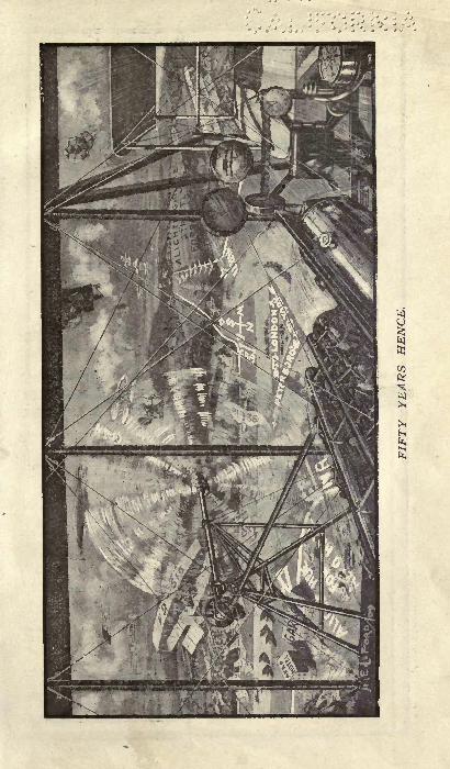
OUR FRONTISPIECE.The scene, as observed from the pilot's seat of an aeroplane,
50 years hence, will show great departures from present-daymethods of locomotion. The difficulty of the aeronaut in ascer-
taining his whereabouts has been overcome by the artist. Tomeet the many difficulties the highways have been considerablywidened, the broad road for motor traffic being bordered oneither side by great green swards, which serve as landing placesfor flying machines. Over these great trackways flying machines
may travel, and, to facilitate night travelling, each track-
way is bordered with a broad band of white chalk so that the
searchlights of the flying machines may pick out the roadboundaries. Each road is given a distinguishing symbol, the
great national roads being lettered N B and numbered. Thusthe aeroplane in the picture is travelling over N R 71, the
great north road between London and York, whilst branch-
ing to the left is C R 3, the county road to Peterborough.The names and the signs are all laid in white chalk set into the
green grass, and the name of each place is similarly shown as
clearly as possible. The artist has assumed that navigation in
the air will be governed by the same rules that control the
navigation of ships at sea. A new regulation is needed only for
the variation of altitude. It can be defined by a parody on the
verse that refers to ships crossing:
If, beneath you, planes appear,It is your duty to keep clear;To act as judgment says is proper,To port or starboard rise, or drop her !
Flying clubs can be seen in the picture at a couple of points,
and the Aero Hotel at Norman Cross has made ample provi-
sion in the way of landing space and machine storage.
PREFACE.
Aeroplane Design and Construction.
By Professor Herbert Chatley, B.Sc., A.M.I.C.E., ImperialEngineering College, North China.
There are quite a number of books on the subject of aviation
which profess to tell the reader how to construct a machine, arid,
doubtless, by the exercise of considerable mental effort, useful
information can be obtained from them, but the average manwho has a bent for mechanical invention and is drawn into the
glamour of this subject, wants to know a few particular thingsand not much more. He is, probably, aware that very few
people know much about the subject, and thinks that, by break-
ing out in a new direction, he may do something fresh. Within
limits, this is probably true. What, then, are the points he
wants to get hold of ?
He hears a lot about gliding angles, skin friction, etc., butthe features that interest him most are sizes, shapes and weights.To start with, what size must a man-carrying machine be?
Well, for every pound weight (including that of itself and the
load) there must be nearly a square foot of supporting surface,so that, when the machine is being designed, the inventor must
figure out whether there is enough surface to support the
weight. This means that there is a considerable width and
length. As may be recognised from the numerous photographsof machines now accessible, the surfaces may be superposed, i.e.,
subdivided and placed in sheets one over another. The only
precaution necessary is that the vertical distance between the
planes must be equal to the smaller dimension thereof. Thus,two surfaces 4 ft. wide must be 4 ft., at least, apart. Further-
more, the surfaces must be narrow in the direction of motion,the breadth across the machine being 10 or 12 times the length.Next, how shall we arrange these surfaces P Well, as far as
present information is concerned, they may be arranged just asone pleases, provided that two rules are observed. The first is
that the centre of gravity (i.e., the place where the whole
weight can be supported without turning) should lie betweenthe surfaces so that the lift on those surfaces shall balance aboutthe centre of gravity.The second is similar to the first, and is that the surfaces must
be symmetrically placed about the centre line.
What shape should the surfaces be ? In section they shouldbe curved if possible in this way : <! < ^-"-""--^-^ <S < Thecurvature should be quite small (about l-12th or less of the
width). In plan, they should taper away from the centre line.
The surfaces should.be fixed in open frames, made of sometough timber with metal joints and good piano-wire stays.
Coupling nuts should be used for tightening the latter. Theframe should be arranged to rest on an under frame supportedby springs on light wheels. The springs should have a totalstiffness equal to at least twice the weight.

Steering is performed by surfaces which can be rotated aboutaxes parallel to the length of the machine, perpendicular to the
length of the machine and parallel to the breadth of themachine. These surfaces should also be balanced about thecentre of gravity. As an alternative, the main surfaces maybe warped, the joints of the frames being able to turn in suit-
able directions, and the planes pulled to the required shape with
controlling wires.
Before the inventor thinks of a motor, he should try the
machine down a slight slope against the wind and see if it will
glide stably. A tail or balancer will probably be necessary at
the rear of the machine. If he finds the machine will glide a
certain number of feet from a given height, then the gliding
height of glide
angle for his machine is measured by the .
length of glide
Multiply this fraction into the weight, and the result is the headresistance of the machine. This should be cut down as much as
possible by carefully shaping all the exposed parts with easilycurved sections so that the wind gets no grip on them.Now as to the motor. If the propeller is properly designed,
the motor should carry about 50 Ib. per brake-horse-power, so
that a machine weighing 1,000 Ib. requires 20 b.h.p. This
assumes, however, that the propeller is a good one, and thatboth it and the motor are running at the best speeds. It will
be wisest for an amateur to purchase his propeller, since thereis considerable knowledge required in the correct formation, andto ascertain what torque is required to drive it at the specified
speed of advance and revolutions. He should then see that themotor is working with high efficiency, and, when direct coupledto the propeller, at the same number of revolutions and withthe same torque. If the propeller is driven through gearing,then the torque and revolutions at the driving shaft should bethe same as that of the propeller. This matter is most im-
portant. No good results can be expected unless the motor,
propeller and aeroplane are in harmony. This involves a further
equality between the propeller thrust and the aeroplane resist-
ance at the specified speed of advance. The resistance will berather higher than that mentioned above as the " head resist-
ance " on account of the surface of the motor and accessories,
and, perhaps, a rather higher speed, but in any case the thrustshould be upwards of one-quarter the total weight.The propellers should run at a level between the superposed
surfaces, so that the head resistance on these is balanced. Well-
designed, moderate-speed propellers are preferable to high-speed small ones. Unless one has thoroughly studied the sub-
ject, the making of a propeller should not even be attempted.For those whose knowledge of mechanics is fairly advanced,
there is plenty of scope for acquiring a fund of preliminaryinformation. It must, however, be realised that no book-
knowledge is comparable with experiment, but the books mayhelp one to avoid unnecessary repetition of work and also to
concentrate research on to the lines of known error and doubt.
HUMAN FLIGHT: THE SOLVEDPROBLEM.
Man, the great adventurer, has sought to penetrate into
every domain, to pry into the habits and methods of all other
living creatures, and to imitate and adopt such of their methodsas should prove interesting and useful to him. And, at last,
after many centuries, he has evolved a machine which shall
give him the mastery of the air as his machines have alreadygiven him the mastery of the land and the sea. He has alwaysenvied the bird and its freedom and sense of easy, perfectmotion, and he has wondered and thought and experimentedand tried, never daunted by failure a thousand times repeated,until the first decade of the twentieth century sees him rise
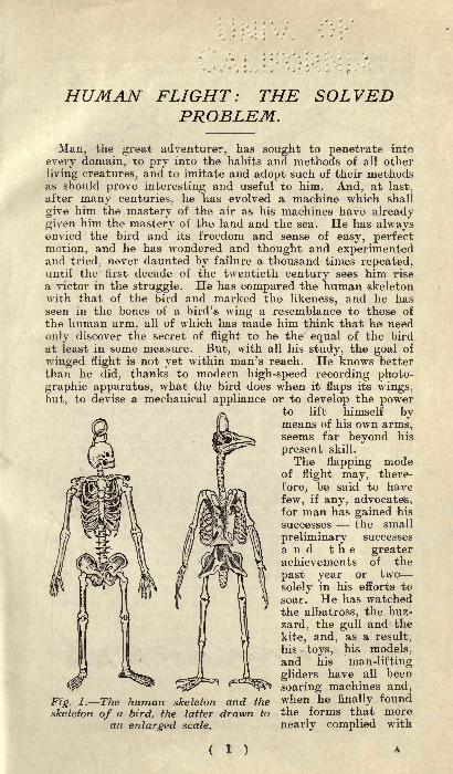
a victor in the struggle. He has compared the human skeletonwith that of the bird and marked the likeness, and he hasseen in the bones of a bird's wing a resemblance to those of
the human arm, all of which has made him think that he need
only discover the secret of flight to be the equal of the bird
at least in some measure. But, with all his study, the goal of
winged flight is not yet within man's reach. He knows betterthan he did, thanks to modern high-speed recording photo-graphic apparatus, what the bird does when it flaps its wings,but, to devise a mechanical appliance or to develop the power
to lift himself bymeans of his own arms,seems far beyond his
present skill.
The flapping modeof flight may, there-
fore, be said to have
few, if any, advocates,for man has gained his
successes the small
preliminary successes
and the greaterachievements of the
past year or two
solely in his efforts to
soar. He has watchedthe albatross, the buz-
zard, the gull and the
kite, and, as a result,his toys, his models,and his man-lifting
gliders have all been
soaring machines and,
Fig. l.The human skeleton and the when he finally found
skeleton of a bird, the latter drawn to the forms that morean enlarged scale, nearly complied with
the conditions laic? dcf.\vj> by nature, Enterprise in another direc-
tion had prepared Joi- him a source' of power light enough forhis purpose, and so, with the petrol engine, he used his adap-tation of the reciprocating action of the tail and fins of the
fish and the
wings of thebird therotary pro-
p e 1 1 e r
and his fly-
ing appara-t u s wascom plete.
And, almostas marvel-lous as this
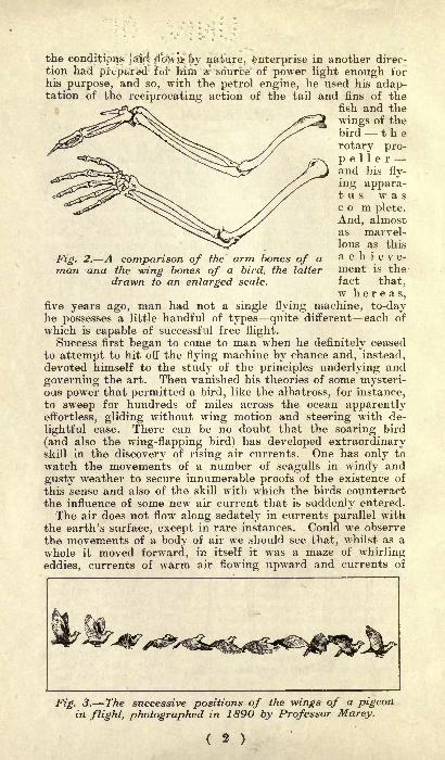
Fig. 2. A comparison of the arm bones of a achieve-man ana the -wing bones of a bird, the latter ment is the
drawn to an enlarged scale. fact that,w h e r e a s,
five years ago, man had not a single flying machine, to-dayhe possesses a little handful of types quite different each of
which is capable of successful free flight.Success first began to come to man when he definitely ceased
to attempt to hit off the flying machine by chance and, instead,devoted himself to the study of the principles underlying and
governing the art. Then vanished his theories of some mysteri-ous power that permitted a bird, like the albatross, for instance,to sweep for hundreds of miles across the ocean apparentlyeffortless, gliding without wing motion and steering with de-
lightful ease. There can be no doubt that the soaring bird
(and also the wing-flapping bird) has developed extraordinaryskill in the discovery of rising air currents. One has only to
watch the movements of a number of seagulls in windy and
gusty weather to secure innumerable proofs of the existence of
this sense and also of the skill with which the birds counteractthe influence of some new air current that is suddenly entered.
The air does not flow along sedately in currents parallel with
the earth's surface, except in rare instances. Could we observe
the movements of a body of air we should see that, whilst as a
whole it moved forward, in itself it was a maze of whirling
eddies, currents of warm air flowing upward and currents of
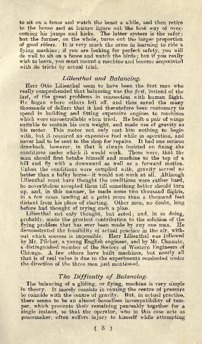
Fig. 3. The successive positions of the wings of a pigeonin flight, photographed in 1890 by Professor Marey.

'
.Fz^. 4. TVze szzccesszve positions of the wings of a seagullflying, with the trajectory of a fixed point on its wing, at Aon a horizontal plane, at B on a vertical plane parallel to
the line of flight, and at C on a vertical plane obliquely to
the line of flight.
cooled air flowing downward to fill the space. Obstructions,such as a cliff face, will deflect the current upward, leaving a
partial void at the summit, into which air will enter in a
whirling mass of eddies. By taking advantage of all risingcurrents the soaring bird is able to lift itself at such intervals
as will allow it to maintain the elevation desired by it. If weregard the bird as being in a constant state of falling by gravitytowards the ground, of utilising this tendency to secure forward
motion, and of opposing it by taking advantage of each risingcurrent of air to maintain or increase its elevation, we get amuch clearer idea of the work which the bird has to do, andwe see that its soaring flights are not so effortless as theyappear. In fact, there is the same deceptiveness about thewalk of a man, for his efforts to maintain a balance are not
noticeable, although they are constantly at work. That manwill never approach the birds in skill is as obvious as is alreadythe fact that he cannot emulate the feats of fish in their ownelement. He has equipped himself to move at moderate speedson the surface of the waters and is content therewith, and hewill equip himself with mechanism that in the air will enablehim to attain a certain level of proficiency and be equallycontent.
That the problem of human flight has been solved is nowbeyond need of argument. The feats and performances of the
past 18 months in 1907, 1908 and 1909 amply support the con-
tention that man has at last planted his foot firmly upon theladder of human flight, and from this time forward advance-ment in design and methods of construction will be rapid.
A2

THE WRIGHT BROTHERS' FIRSTGLIDING EXPERIMENTS.
As related by Mr. Wilbur Wright before the Society of Western
Engineers of Chicago, on September 18th, 1901.
__-The difficulties which obstruct the pathway to success in flying-machine construction are of three general classes : (1) Thosewhich relate to the construction of the sustaining wings ; (2)-those which relate to the generation and application of the
power required to drive the machine through the air; (3) those
^relating to the balancing and steering of the machine after it is
actually in flight. Of these difficulties, two are already to acertain extent solved. Men already know how to construct
wings or aeroplanes, which, when driven through the air at
sufficient speed, will not only sustain the weight of the wingsthemselves, but also that of the engine and of the engineer as
well. Men also know how to build engines and screws of suffi-
cient lightness and power to drive these planes at sustainingspeed. As long ago as 1893 a machine weighing 8,0001b.* de-
monstrated its power both to lift itself from the ground and to
maintain a speed of from 30 to 40 miles per hour;but it came to
grief in an accidental free flight, owing to the inability of the
operators to balance and steer it properly. This inability to
balance and steer still confronts students of the flying problem,although nearly ten years have passed. When this one featurehas been worked out, the age of flying machines will have
arrived, for all other difficulties are of minor importance.The person who merely watches the flight of a bird gathers
the impression that the bird has nothing to think of but the
flapping of its wings. As a matter of fact, this is a very small partof its mental labour. To even mention all the things the bird
must constantly keep in mind, in order to fly securely throughthe air, wpuld take a considerable time. If I take a piece of
paper, and after placing it parallel with the ground, quickly let
it fall, it will not settle steadily down as a staid, sensible pieceof paper ought to do, but it insists on contravening every recog-nised rule of decorum, turning over and darting hither andthither in the most erratic manner, much after the style of anuntrained horse. Yet this is the style of steed that men must'earn to manage before flying can become an every-day sport.The bird has learned this art of equilibrium, and learnt it so
thoroughly that its skill is not apparent to our sight. We onlylearn to appreciate it when we try to imitate it.
Now, there are only two ways of learning how to ride a
fractious horse : one is to get on him and learn by actual prac-tice how each motion and trick may be best met; the other is
* Made by Maxim.
( 4 )
to sit on a fence and watch the beast a while, and then retire
to the house and at leisure figure out the best way of over-
coming his jumps and kicks. The latter system is the safer;
but the former, on the whole, turns out the larger proportionof good riders. It is very much the same in learning to ride a
flying machine;
if you are looking for perfect safety, you will
do well to sit on a fence and watch the birds;but if you really
wish to learn, you must mount a machine and become acquaintedwith its tricks by actual trial.
Lilienthal and Balancing.Herr Otto Lilienthal seem to have been the first man who
really comprehended that balancing was the first, instead of the
last, of the great problems in connection with human flight.He began where others left off, and thus saved the manythousands of dollars that it had theretofore been customary to
spend in building and fitting expensive engines to machineswhich were uncontrollable when tried. He built a pair of wingssuitable to sustain his own weight, and made use of gravity as
his motor. This motor not only cost him nothing to beginwith, but it required no expensive fuel while in operation, andnever had to be sent to the shop for repairs. It had one serious
drawback, however, in that it always insisted on fixing theconditions under which it would work. These were, that theman should first betake himself and machine to the top of a
hill and fly with a downward as well as a forward motion.Unless the conditions were complied with, gravity served nobetter than a balky horse it would not work at all. AlthoughLilienthal must have thought the conditions were rather hard,he nevertheless accepted them till something better should turn
up, and, in this manner, he made some two thousand flights,in a few cases landing at a point more than a thousand feet
distant from his place of starting. Other men, no doubt, longbefore had thought of trying such a plan.
Lilienthal not only thought, but acted; and, in so doing,
probably, made the greatest contribution to the solution of the
flying problem that has ever been made by any one man. Hedemonstrated the feasibility of actual practice in the air, with-out which success is impossible. Herr Lilienthal was followed
by Mr. Pilcher, a young English engineer, and by Mr. Chanute,a distinguished member of the Society of Western Engineers of
Chicago. A few others have built machines, but nearly all
that is of real value is due to the experiments conducted underthe direction of the three men just mentioned.
The Difficulty of Balancing.The balancing of a gliding, or flying, machine is very simple
in theory. It merely consists in causing the centre of pressureto coincide with the centre of gravity. But, in actual practice,there seems to be an almost -boundless incompatibility of tem-
per, which prevents their remaining peaceably together for a
single instant, so that the operator, who in this case acts as
peacemaker, often suffers injury to himself while attempting
( 5 )
to bring them together. If a wind strikes a vertical plane, the
pressure on that part to one side of the centre will exactlybalance that on the other side, and the part above the centrewill balance that below. This point we call the centre of
pressure. But if the plane be slightly inclined, the pressure onthe part nearest the wind is increased, and the pressure on theother part decreased, so that the centre of pressure is nowlocated, not in the centre of the surface, but a little towardsthe side which is in advance. If the plane be still further in-
clined, the centre of pressurewill move still farther forward.
And, if the wind blow a little,
to one side, it will also moveover as if to meet it. Now,since neither the wind nor the
machine, for even an instant,maintains exactly the samedirection and velocity, it is evi-
dent that the man who wouldtrace the course of the centre of
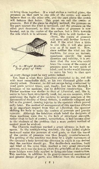
Fig. 5. Wright Brothers'pressure must be very quick of
first ghder of 1900. mind . and ^e who would attemptto move his body to that spot
at every change must be very active indeed.
Yet, that is what Herr Lilienthal attempted to do, and did
with most remarkable skill, as his two thousand glides suffi-
ciently attest. However, he did not escape being overturned bywind gusts several times, and, finally, lost his life through a
breakage of his machine, due to defective construction. ThePilcher machine was similar to that of Lilienthal, and, like it,
seems to have been structurally weak, for, on one occasion, while
exhibiting the flight of his machine to several members of theAeronautical Society of Great Britain, it suddenly collapsed andfell to the ground, causing injuries to the operator which provedsadly fatal. The method of management of this machine differed
in no important respect from that of Lilienthal, the operatorshifting his body to make the centres of pressure and gravitycoincide. Although the fatalities which befell the designers of
these machines were due to the lack of structural strength,rather than to lack of control, nevertheless, it had become clear
to the students of the problem that a more perfect method of
control must be evolved.
The Chanute machines marked a great advance in both re-
spects. In the multiple-wing machine, the tips folded slightlybackward under the pressure of wind gusts, so that the travel
of the centre of pressure was thus largely counterbalanced.The guiding of the machine was done by a slight movement of
the operator's body toward the direction in which it was desired
that the machine should go. The double-deck machine, built
and tried at the same time, marked a very great structural
advance, as it was the first in which the principles of the moderntruss .bridges were fully applied to flying-machine construction.This machine, in addition to its greatly-improved construction
and general design of parts, also differed from the machine of
( 6 )
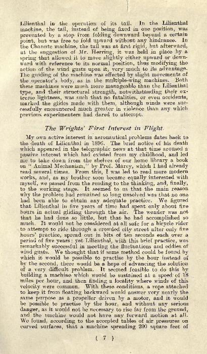
Lilienthal in the operation of its tail. In the Lilienthal
machine, the tail, instead of being fixed in one position, was
prevented by a stop from folding downward beyond a certain
point, but was free to fold upward without any hindrance. In
the Chanute machine, the tail was at first rigid, but afterward,at the suggestion of Mr. Herring, it was held in place by a
spring that allowed it to move slightly either upward or down-ward with reference to its normal position, thus modifying the
action of the wind gusts upon it, very much to its advantage.The guiding of the machine was effected by slight movements of
the operator's body, as in the multiple-wing machines. Boththese machines were much more manageable than the Lilienthal
type, and their structural strength, notwithstanding their ex-
treme lightness, was such that no fatalities, or even accidents,
marked the glides made with them, although winds were suc-
cessfully encountered much greater in violence than any which
previous experimenters had dared to attempt.
The Wrights' First Interest in Flight.
My own active interest in aeronautical problems dates back to
the death of Lilienthal in 1896. The brief notice of his deathwhich appeared in the telegraphic news at that time aroused a
passive interest which had existed from my childhood, and led
me to take down from the shelves of our home library a bookon " Animal Mechanism," by Prof. Marey, which I had alreadyread several times. From this, I was led to read more modernworks, and, as my brother soon became equally interested with
myself, we passed from the reading to the thinking, and, finally,
to the working stage. It seemed to us that the main reason
why the problem had remained so long unsolved was that no onehad been able to obtain any adequate practice. We figuredthat Lilienthal in five years of time had spent only about five
hours in actual gliding through the air. The wonder was notthat he had done so little, but that he had accomplished so
much. It would not be considered at all safe for a bicycle rider
to attempt to ride through a crowded city street after only five
hours' practice, spread out in bits of ten seconds each over a
period of five years ; yet Lilienthal, with this brief practice, was
remarkably successful in meeting the fluctuations and eddies of
wind gusts. We thought that if some method could be found bywhich it would be possible to practise by the hour instead of
by the second, there would be a hope of advancing the solutionof a very difficult problem. It seemed feasible to do this bybuilding a machine which would be sustained at a speed of 18miles per hour, and then finding a locality where winds of this
velocity were common. With these conditions, a rope attachedto keep it from floating backward would answer very nearly thesame purpose as a propeller driven by a motor, and it wouldbe possible to practise by the hour, and without any serious
danger, as it would not be necessary to rise far from the ground,and the machine would not have any forward motion at all.
We found, according to the accepted tables of air pressures oncurved surfaces, that a machine spreading 200 square feet of
( 7 )
wing surface would be sufficient for our purpose, and that placescould easily be found along the Atlantic coast where winds of
16 to 25 miles were not at all uncommon. When the winds were
low, it was our plan to glide from the tops of sand hills, andwhen they were sufficiently strong, to use a rope for our motorand fly over one spot.Our next work was to draw up the plans for a suitable
machine. After much study, we finally concluded that tails
were a source of trouble rather than of assistance; and, there-
fore, we decided to dispense with them altogether. It seemedreasonable that, if the body of the operator could be placed in
a horizontal position instead of the upright, as in the machinesof Lilienthal, Pilcher, and Chanute, the wind resistance couldbe very materially reduced, since only one square foot instead
of five would be exposed. As a full half-horse-power could besaved by this change, we arranged to try at least the horizontal
position. Then, the method of control used by Lilienthal, whichconsisted in shifting the body, did not seem quite as quick or
effective as the case required ; so, after long study, we contriveda system consisting of two large surfaces on the Chanute double-deck plan, and a smaller surface placed a short distance in
front of the main surfaces in such a position that the action of
the wind upon it would counterbalance the effect of the travel
of the centre of pressure on the main surfaces. Thus, changesin the direction and velocity of the wind would have little dis-
turbing effect, and the operator would be required to attend
only to the steering of the machine, which was to be effected bycurving the forward surface up or down. The lateral equilibriumand the steering to right or left were to be attained by a peculiartorsion of the main surfaces, which was equivalent to presentingone end of the wings at a greater angle than the other. In the
main frame 1
,a few changes were also made in the details of
construction and trussing employed by Mr. Chanute. Themost important of these were : (1) the moving of the forwardmain cross-piece of the frame to the extreme front edge ; (2)
the encasing in the cloth of all cross-pieces and ribs of the
surfaces; (3) a rearrangement of the wires used in trussing the
two surfaces together, which rendered it possible to tighten all
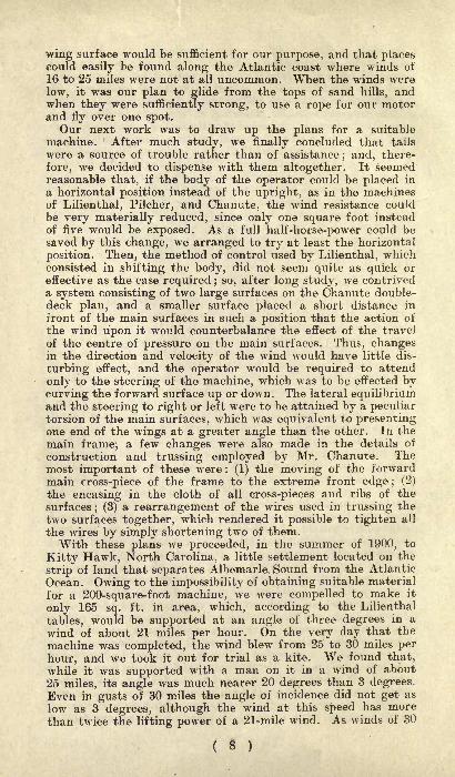
the wires by simply shortening two of them.With these plans we proceeded, in the summer of 1900, to
Kitty Hawk, North Carolina, a little settlement located on the
strip of land that separates Albemarle. Sound from the Atlantic
Ocean. Owing to the impossibility of obtaining suitable material
for a 200-square-foot machine, we were compelled to make it
only 165 sq. ft. in area, which, according to the Lilienthal
tables, would be supported at an angle of three degrees in a
wind of about 21 miles per hour. On the very day that the
machine was completed, the wind blew from 25 to 30 miles per
hour, and we took it out for trial as a kite. We found that,
while it was supported with a man on it in a wind of about
25 miles, its angle was much nearer 20 degrees than 3 degrees.Even in gusts of 30 miles the angle of incidence did not get as
low as 3 degrees, although the wind at this speed has more
than twice the lifting power of a 21-mile wind. As winds of 30
( 8 )

miles per hour are not plentiful on clear days, it was at once
evident that our plan of practising by the hour, day after day,would have to be postponed. Our system of twisting the sur-
faces to regulate the lateral balance was tried and found to be
much more effective than shifting the operator's body. On
subsequent days, when the wind was too light to support the
machine with a man on it, we tested it as a kite, working the
rudders by cords reaching to the ground. The results were very
satisfactory, yet we were well aware that this method of testing
is never wholly convincing until the results are confirmed byactual gliding experience.
Lift and Drift Experiments.
We then turned our attention to making a series of actual
measurements of the lift and drift of the machine under various
loads. So far as we were aware, this had never previously been
done with any full-size machine. The results obtained weremost astonishing, for it appeared that the total horizontal pullof the machine, while sustaining a weight of 521b., was only
S.olb., which was less than had previously been estimated for
head resistance of the framing alone. Making allowance for the
weight carried, it appeared that the head resistance of the fram-
ing was little more than 50 per cent, of the amount which Mr.Chanute had estimated as the head resistance of the framingof his machine. On the other hand, it appeared sadly deficient
in lifting power as compared with the calculated lift of curvedsurfaces of its size. This deficiency we supposed might be due to
one or more of the following causes : (1) That the depth of the
curvature of our surfaces was insufficient, being only about 1 in
22, instead of 1 in 12; (2) that the cloth used in our wings was
not sufficiently airtight; (3) that the Lilienthal tables mightthemselves be somewhat in error. We decided to arrange our
machine for the following year so that the depth of curvature of
its surfaces could be varied at will, and its covering air-proofed.Our attention was next turned to gliding, but no hill suitable
for the purpose could be found near our camp at Kitty Hawk.This compelled us to take the machine to a point four miles
south, where the Kill Devil sandhill rises from the flat sand to
a height of more than 100ft. Its main slope is toward the
north-east and has an inclination of 10 degrees. On the day ot
our arrival the wind blew about 25 miles an hour, and, as
we had had no experience at all in gliding, we deemed it unsafe
to attempt to leave the ground. But, on the day following,the wind having subsided to 14 miles per hour, we made abouta dozen glides. It had been the original intention that the
operator should run with the machine to obtain initial velocity,and assume the horizontal position only after the machine wasin free flight. When it came time to land he was to resumethe upright position and alight on his feet, after the style of
previous gliding experimenters. But, on actual trial, we foundit much better to employ the help of two assistants in starting,which the peculiar form of our machine enabled us readily to
do; and, in landing, we found that it was entirely practicable
( 9 )
to land while still reclining in a horizontal position upon themachine. Although the landings were made while moving at
speeds of more than 20 miles an hour, neither machine noroperator suffered any injury.The slope of the hill was 9.5 degrees, or a drop of 1ft. in 6ft.
We found that, after attaining a speed of about 25 or 30 mileswith reference to the wind, or 10 to 15 miles over the ground,the machine not only glided parallel to the slope of the hill,
but greatly increased its speed, thus indicating its ability to
glide on a somewhat less angle than 9.5 degrees, when we shouldfeel it safe to rise higher from the surface. The control of themachine proved even better than we had dared to pxpect, re-
sponding quickly to the slightest motion of the rudder.
The Conclusions of 1900.With these glides our experiments for the year 1900 closed.
Although the hours and hours of practice we had hoped toobtain finally dwindled down to about two minutes, we were verymuch pleased with the general results of the trip, for, settingout as we did, with almost revolutionary theories on manypoints and an entirely untried form of machine, we consideredit quite a point to be able to return without having our pettheories completely knocked on the head by' the hard logic of
experience, and our own brains dashed out in the bargain.
Everything seemed to us to confirm the correctness of our
original opinions : (1) that practice is the key to the secret of
flying; (2) that it is practicable to assume the horizontal posi-tion
; (3) that a smaller surface set at a negative angle in frontof the main bearing surfaces or wings will largely counteractthe effect of the fore and aft travel of the centre of pressure ;
(4) that steering up and down can be attained with a rudder,without moving the position of the operator's body; (5) that
twisting the wings so as to present their ends to the wind at
different angles is a "more prompt and efficient way of main-
taining lateral equilibrium than shifting the body of the
operator.
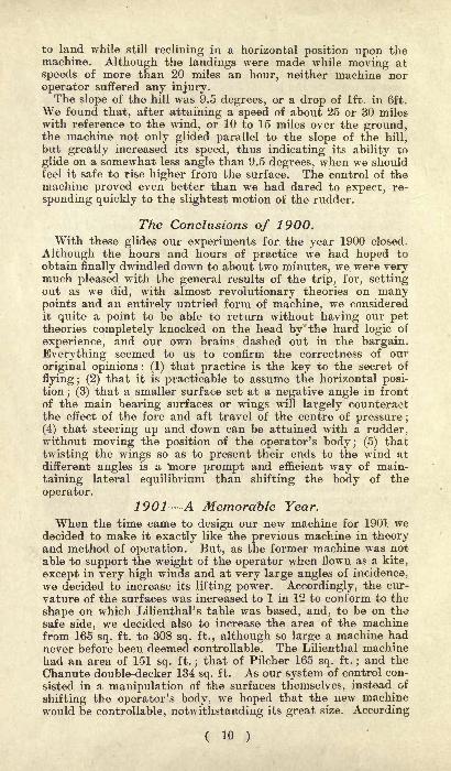
1901 A Memorable Year.
When the time came to design our new machine for 1901 wedecided to make it exactly like the previous machine in theoryand method of operation. But, as the former machine was not
able to support the weight of the operator when flown as a kite,
except in very high winds and at very large angles of incidence,we decided to increase its lifting power. Accordingly, the cur-
vature of the surfaces was increased to 1 in 12 to conform to the
shape on which Lilienthal's table was based, and, to be on thesafe side, we decided also to increase the area of the machinefrom 165 sq. ft. to 308 sq. ft., although so large a machine hadnever before been deemed controllable. The Lilienthal machinehad an area of 151 sq. ft.
;that of Pilcher 165 sq. ft.
;and the
Chanute double-decker 134 sq. ft. As our system of control con-
sisted in a manipulation of the surfaces themselves, instead of
shifting the operator's body, we hoped that the new machinewould be controllable, notwithstanding its great size. According
( 10 )
to our calculations, it would obtain support in a wind of 17 miles
per hour with an angle of incidence of only 3 degrees.Our experience of the previous year having shown the necessity
of a suitable building for housing the machine, we erected a
cheap frame building 16ft. wide, 25ft. long, and 7ft. high atthe eaves. As our machine was 22ft. wide, 14ft. long (includingthe rudder) and about 6ft. high, it was not necessary to takethe machine apart in any way in order to house it. Both endsof the building, except the gable parts, were made into doors,which hinged above, so that when opened they formed an
awning at each end, and left an entrance the full width of the
building. We went into camp about the middle of July, andwere soon joined by Mr. E. C. Huffaker, of Tennessee, an ex-
perienced aeronautical investigator in the employ of Mr. Cha-nute, by whom his services were kindly loaned, and by Dr.G. A. Spratt, of Pennsylvania, a young man who has made somevaluable investigations of the properties of variously-curved sur-
faces and the travel of the centre of pressure thereon. Earlyin August Mr. Chanute came down from Chicago to witnessour experiments, and spent a week in camp with us.
The machine was completed and tried for the first time on
July 27th in a wind blowing about 13 miles an hour. Theoperator having taken a position where the centre of pressurewas supposed to be, an attempt at gliding was made
;but the
machine turned downward and landed after going only a few
yards. This indicated that the centre of gravity was too far
in front of the centre of pressure. In the second attempt the
operator took a position several inches further back, but theresult was much the same. He kept moving further and furtherback with each trial, till finally he occupied a position nearly afoot back of that at which we had expected to find the centreof pressure. The machine then sailed off, and made an undulat-
ing flight of a little more than 300ft. To the onlookers this
flight seemed very successful, but, to the operator, it was knownthat the full power of the rudder had been required to keepthe machine from either running into the ground or rising so
high as to lose all headway. In the 1900 machine one-fourthas much rudder action had been sufficient to give much bettercontrol. It was apparent that something was radically wrong,though we were for some time unable to locate the trouble.
In one glide the machine rose higher and higher till it lost
all headway. This was the position from which Lilienthal had
always found difficulty in extricating himself, as his machine
then, in spite of his greatest exertions, manifested a tendencyto dive downward almost vertically and strike the ground headon with frightful velocity. In this case a warning cry from the
ground caused the operator to turn the rudder to its full extentand also to move his body slightly forward. The machine thensettled slowly to the ground, maintaining its horizontal positionalmost perfectly, and landed without any injury at all.
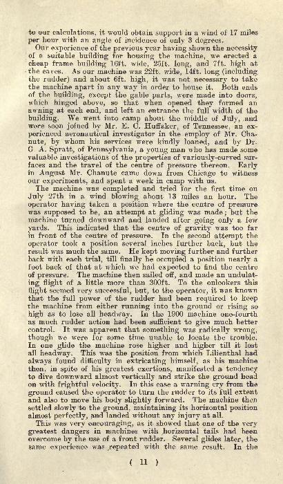
This was very encouraging, as it showed that one of the verygreatest dangers in machines with horizontal tails had beenovercome by the use of a front rudder. Several glides later, thesame experience was repeated with the same result. In the
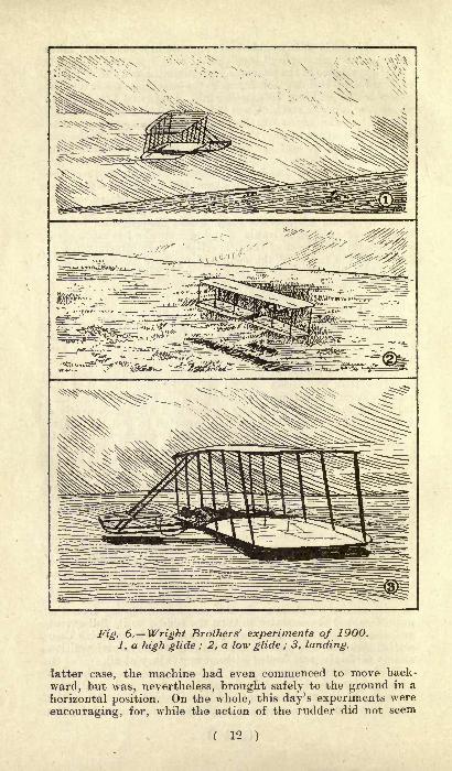
jr^. 6. Wright Brothers' experiments of 1900.
1, a high glide ; 2, a low glide ; 3, landing,
latter case, the machine had even commenced to move back-
ward, but was, nevertheless, brought safely to the ground in a
horizontal position. On the whole, this day's experiments were
encouraging, for, while the action of the rudder did not seem
( 12 )

at all like that of our 1900 machine, yet we had escaped without
difficulty from positions which had proved very dangerous to
preceding experimenters, and, after less than one minute's
actual practice, had made a glide of more than 300 feet, at an
angle of descent of 10 degrees, and with a machine nearly twiceas large as had previously been considered safe.
The trouble with its control, which has been mentioned, webelieved could be corrected when we should have located its
cause. Several possible explanations occurred to us, but we
finally concluded that the trouble was due to a reversal of the
direction of the travel of the centre of pressure at small angles.In deeply-curved surfaces, the centre of pressure at 90 degreesis near the centre of the surface, but moves forward as the anglebecomes less, till a certain point is reached, varying with the
depth of curvature. After this point is passed, the centre of
pressure, instead of continuing to move forward, with the de-
creasing angle, turns and moves rapidly towards the rear. Thephenomena are due to the fact that, at small angles, the windstrikes the forward part of the surface on the upper side insteadof the lower, and, thus, this part altogether ceases to lift, in-
stead of being the most effective part of all, as in the case of
the plane. Lilienthal had called attention to the danger of
using surfaces with a curvature as great as one in eight, onaccount of this action on the upper side
;but he seems never to
have investigated the curvature and angle at which the pheno-mena entirely cease.
My brother and I had never made any original investigationof the matter, but assumed that a curvature of 1 in 12 wouldbe safe, as this was the curvature on which Lilienthal based his
tables. However, to be on the safe side, instead of using thearc of a circle, we had made the curve of our machine veryabrupt at the front, so as to expose the least possible area tothis downward pressure. While the machine was building,Messrs. Huffaker and Spratt had suggested that we would find
this reversal of the centre of pressure, but we believed it suffi-
ciently guarded against. Accordingly, we were not at first disposedto believe that this reversal actually existed in our machine,although it offered a perfect explanation of the action we hadnoticed in gliding. Our peculiar plan of control by forward
surfaces, instead of tails, was based on the assumption that the
Fig. 7.C, cord ; Pr
centre of pressure ;
G, centre of gravity.
( 13 )
centre of pressure would continue to move farther and farther
forward, as the angle of incidence became less, and it will be
readily perceived that it would make quite a difference if thefront surface, instead of counteracting this assumed forward
travel, should in reality be expediting an actual backward move-ment. For several days we were in a state of indecision, butwere finally convinced, by observing the following phenomena(Fig. 7). We had removed the upper surface from the machine andwere flying it in a wind, to see at what angles it would be sup-ported in winds of different strengths. We noticed that, in lightwinds, it flew in the upper position (X) shown in the figure,with a strong upward pull on the cord (C). As the wind became
stronger, the angle of incidence became less, and the surfaceflew in the position shown in the middle of the figure, with a
slight horizontal pull. But when the wind became still stronger,it took the lower position shown in the figure, with a strongdownward pull. It at once occurred to me that here was theanswer to our problem, for it is evident that, in the first case,the centre of pressure was in front of the centre of gravity andthen pushed up the front edge ;
in the second case, they were in
coincidence, and the surface in equilibrium, while, in the third
case, the centre of pressure had reached a point even behindthe centre of gravity, and there was therefore a downward pullon the cord. This point having been definitely settled, we pro-ceeded to truss down the ribs of the whole machine, so as to
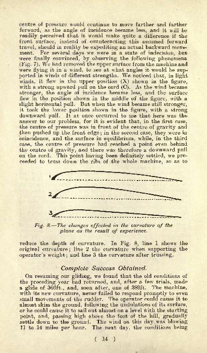
Fig. 8. The changes effected in the curvature of the
plane as the result of experience.
reduce the depth of curvature. In Fig. 8, line 1 shows the
original curvature;line 2 the curvature when supporting the
operator's weight; and line 3 the curvature after trussing.
Complete Success Obtained.
On resuming our gliding, we found that the old conditions of
the preceding year had returned, and, after a few trials, madea glide of 366ft., and, soon after, one of 389ft. The machine,with its new curvature, never failed to respond promptly to evensmall movements of the rudder. The operator could cause it to
almost skim the ground, following the undulations of its surface,or he could cause it to sail out almost on a level with the starting
point, and, passing high above the foot of the hill, graduallysettle down to the ground. The wind on this day was blowing11 to 14 miles per hour. The next day, the conditions being
( 14 )
favourable, the machine was again taken out for trial. This
time the velocity of the wind was 18 to 22 miles per hour. Atfirst we felt some doubt as to the safety of attempting free flightin so strong a wind, with a machine of over 300 sq. ft., and a
practice of less than five minutes spent in actual flight. But,after several preliminary experiments, we decided to try a glide.The control of the machine seemed so good that we then felt no
apprehension in sailing boldly forth. And, thereafter, we made
glide after glide, sometimes following the ground closely, andsometimes sailing high in the air. Mr. Chanute had his camerawith him, and took pictures of some of these glides.We made glides on subsequent days, whenever the conditions
were favourable. The highest wind thus experimented in wasa little over 12 metres per second nearly 27 miles per hour.
It had been our intention, when building the machine, to do
the larger part of the experimenting in the following manner :
When the wind blew 17 miles an hour, or more, we would attach
a rope to the machine and let it rise as a kite with the operator
upon it. When it should reach a proper height, the operatorwould cast off the rope and glide down to the ground just as fromthe top of a hill. In this way, we would be saved the trouble of
carrying the machine up hill after each glide, and could makeat least 10 glides in the time required for one in the other way.But when we came to try it we found that a wind of 17 miles,
as measured by Richard's anemometer, instead of sustaining the
machine with its operator, a total weight of 2401b., at an angleof incidence of three degrees, in reality would not sustain the
machine alone lOOlb. at this angle. Its lifting capacityseemed scarcely one-third of the calculated amount. In order
to make sure that this was not due to the porosity of the cloth,
we constructed two small experimental surfaces of equal size,
one of which was air-proofed and the other left in its natural
state;but we could detect no difference in their lifting powers.
For a time, Ave were led to suspect that the lift of curved sur-
faces little exceeded that of planes of the same size, but further
investigation and experiment led to the opinion that (1) the
anemometer used by us over-recorded the true velocity of the
wind by nearly 15 per cent. ; (2) that the well-known Smeatoncoefficient of .005 V2 for the wind pressure at 90 degrees is
probably too great by at least 20 per cent.; (3) that Lilienthal's
estimate that the pressure on a curved surface having an angleof incidence of 3 degrees equals .545 of the pressure of 90 degreesis too large, being nearly 50 per cent, greater than very recent
experiments of our own with a special pressure-testing machine
indicator ; (4) that the superposition of the surfaces somewhatreduced the lift per square foot, as compared with a single
surface of equal area.
The Importance of the Ratio of Lift to Drift.
In gliding experiments, however, the amount of lift is of less
relative importance than the ratio of lift to drift, as this alone
decides the angle of gliding descent. In a plane, the pressureis always perpendicular to the surface, and the ratio of lift to
( 15 )
drift is therefore the same as that of the cosine to the sine of the
angle of incidence. But, in curved surfaces, a very remarkable
situation is found. The pressure, instead of being uniformlynormal to the chord of the arc, is usually inclined considerablyin front of the perpendicular. The result is that the lift is
greater and the drift less than if the pressure were normal.
Lilienthal was the first to discover this exceedingly importantfact, which is fully set forth in his book,
" Bird Flight the
Basis of the Flying Art," but, owing to some errors in the
methods he used in making measurements, question was raised
by other investigators not only as to the accuracy of his figures,but even as to the existence of any tangential force at all. Our
experiments confirm the existence of this force, though our mea-surements differ considerably from those of Lilienthal. Whileat Kitty Hawk, we spent much time in measuring the horizontal
pressure on our unloaded machine at various angles of incidence.
We found that at 13 degrees the horizontal pressure was about231b. This included not only the drift proper, or horizontal
component of the pressure on the side of the surface, but also
the head resistance of the framing as well. The weight of the
machine at the time of this test was about 1081b. Now, if the
pressure had been normal to the chord of the surface, the drift
proper would have been to the lift (1081b.), as the sine of
.22 X 10813 degrees is to the cosine of 13 degrees or = 24^ Ib.
;
.97
but this slightly exceeds the total pull of 231b. on our scales.
Therefore, it is evident that the average pressure on the sur-
face, instead of being normal to the chord, was so far inclined
toward the front that all the head resistance of framing andwires used in the construction was more than overcome. In awind of 14 miles per hour resistance is by no means a negligiblefactor, so that tangential force is evidently a force of consider-able value. In a higher wind, which sustained the machine atan angle of 10 degrees, the pull on the scales was 181b. Withthe pressure normal to the chord, the drift proper would have
.17 X 98been = 171b., so that although the higher wind
.98
velocity must have caused an increase in the head resistance, the
tangential force still came within lib. of overcoming it.
Pressures on Curved Surfaces.
After our return from Kitty Hawk, we began a series of ex-
periments to accurately determine the amount and direction ofthe pressure produced on curved surfaces when acted upon bywinds at the various angles from zero to 90 degrees. These ex-
periments are not yet concluded, but, in general, they supportLilienthal in the claim that the curves give pressures morefavourable in amount and direction than planes ;
but we findmarked differences in the exact values, especially at anglesbelow 10 degrees.We were unable to obtain direct measurements of the
( 16 )
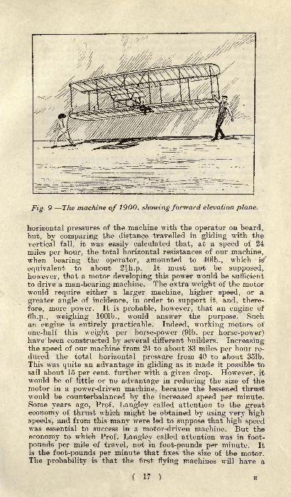
Fig. 9 The machine of 1900, showing forward elevation plane.
horizontal pressures of the machine with the operator on board,
but, by comparing the distance travelled in gliding with thevertical fall, it was easily calculated that, at a speed of 24
miles per hour, the total horizontal resistances of our machine,when bearing the operator, amounted to 401b., which is''
equivalent to about 2^h.p. It must not be supposed,however, that a motor developing this power would be sufficient
to drive a man-bearing machine. The extra weight of the motorwould require either a larger machine, higher speed, or a
greater angle of incidence, in order to support it, and, there-
fore, more power. It is probable, however, that an engine of
6h.p., weighing lOOlb., would answer the purpose. Suchan engine is entirely practicable. Indeed, working motors ofone-half this weight per horse-power (91b. per horse-power)have been constructed by several different builders. Increasingthe speed of our machine from 24 to about 33 miles per hour re-
duced the total horizontal pressure from 40 to about 351b.
This was quite an advantage in gliding as it made it possible tosail about 15 per cent, further with a given drop. However, it
would be of little or no advantage in reducing the size of themotor in a power-driven machine, because the lessened thrustwould be counterbalanced by the increased speed per minute.Some years ago, Prof. Langley called attention to the greateconomy of thrust which might be obtained by using very highspeeds, and from this many were led to suppose that high speedwas essential to success in a motor-driven machine. But the
economy to which Prof. Langley called attention was in foot-
pounds per mile of travel, not in foot-pounds per minute. Itis the foot-pounds per minute that fixes the size of the motor.The probability is that the first flying machines will have a
( 17 ) B
relatively low speed, perhaps not much exceeding 20 miles perhour, but the problem of increasing the speed will be muchsimpler in some respects than that ot increasing the speed of a
steamboat, for, whereas in 'the latter case the size of the enginemust increase as the cube of the speed in the flying machineuntil extremely high speeds are reached, the capacity of themotor increases in less than simple ratio
;and there is even a
decrease in the fuel consumption per mile of travel. In other
words, to double the speed of a steamship (and the same is trueof thfc balloon type of airship) eight times the engine and boiler
capacity would be required, and four times the fuel consumptionper mile of travel; while a flying machine would require en-
gines of less than double the size, and there would be an actualdecrease in the fuel consumption per mile of travel.
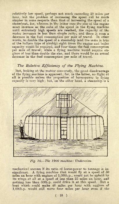
The Relative Efficiency of the Flying Machine.
But, looking at the matter conversely, the great disadvantageof the flying machine is apparent ; for, in the latter, no flight atall is possible unless the proportion of horse-power to flying
capacity is very high; but, on the other hand, a steamship'is a
Fig. 10. The 1900 machine: Under-view.
mechanical success if its ratio of horse-power to tonnage is in-
significant. A flying machine that would fly at a speed of 50miles an hour with engines of l,000h.p., would not be upheld byits wings at all at a speed of less than 25 miles an hour, and
nothing less than 500h.p. could drive it at this speed. But a
boat which could make 40 miles per hour with engines of
l,000h.p. would still move four miles per hour even if the
( 18 )

engines were reduced to Ih.p. The problems of land and watertravel were solved in the 19th century, because it was possibleto begin with small achievements and gradually work up to our
present success. The flying problem was left over to the 20th
century, because, in this case, the art must be highly developedbefore any flight of any considerable duration at all can beobtained.
However, there is another way of flying which requires noartificial motor, and many workers believe that success will first
come by this road. I refer to the soaring flight, by which .the
machine is permanently sustained in the air by the same meansthat are employed by soaring birds. They spread their wingsto the wind, and sail by the hour, with no perceptible exertion
beyond that required to balance and steer themselves. Whatsustains them is not definitely known, though it is almost cer-
Fig. 11. A soaring flight, the machine being practicallyat a standstill.
tain that it is a rising current of air. But, whether it be a
rising current or something else, it is as well able to supporta flying machine as a bird, if man once learns the art of
utilising it. In gliding experiments it has long been knownthat the rate of vertical descent is very much retarded and the
duration of the flight greatly prolonged if a strong wind blows
up the face of the hill parallel to its surface. Our machine,when gliding in still air, has a rate of vertical descent of nearly6ft. per second, while in a wind blowing 26 miles per hour up a
steep hill we made glides in which the rate of descent was less
than 2ft. per second; and, during the larger part of this- time,
( 19 ) B2
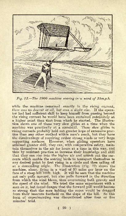
Fig. 12. The 1900 machine soaring in a wind of 35m.p.h.
while the machine remained exactly in the rising current,there was no descent at all, but even a slight rise. If the opera-tor had had sufficient skill to keep himself from passing beyondthe rising current he would have been sustained indefinitely ata higher point than that from which he started. The illustra-
tion shows one of these very slow glides at a time when themachine was practically at a standstill. These slow glides in
rising currents probably hold out greater hope of extensive prac-tice than any other method within man's reach, but they havethe disadvantage of requiring rather strong winds or very large
supporting surfaces. However, when gliding operators haveattained greater skill, they can, with comparative safety, main-tain themselves in the air for hours at a time in this way, andthus by con'stant practice so increase their knowledge and skill
that they can rise into the higher air and search out the cur-
rents which enable the soaring birds to transport themselves to
any desired point by first rising in a circle and then sailing off
at a descending angle. The illustration (Fig. 12) shows the
machine, alone, flying in a wind of 35 miles per hour on theface of a steep hill 100ft. high. It will be seen that the machinenot only pulls upward, but also pulls forward in the direction
from which the wind blows, thus overcoming both gravity andthe speed of the wind. We tried the same experiment with a
man on it, but found danger that the forward pull would becomeso strong that the men holding the ropes would be draggedfrom their insecure foothold on the slope of the hill. So this
form of experimenting was discontinued after four or five
minutes' trial.

The Conclusions of 1901.
In looking over our experiments of the past two years, with
models and full-size machines, the following points stand outwith clearness :
1. That the lifting power of a large machine, held stationaryin a wind at a small distance from the earth, is much less thanthe Lilienthal table and our own laboratory experiments wouldlead us to expect. When the machine is moved through the air,
as in gliding, the discrepancy seems much less marked.2. That the ratio of drift to lift in well-shaped surfaces is less
at angles of incidence of 5 degrees to 12 degrees than at an
angle of 3 degrees.3. That, in arched surfaces, the centre of pressure at 90 de-
grees is near the centre of the surface, but moves slowly forwardas the angle becomes less, till a critical angle varying with the
shape and depth of the curve is reached, after which it movesrapidly toward the rear till the angle of no lift is found.
4. That, with similar conditions, large surfaces may be con-trolled with not much greater difficulty than small ones, if thecontrol is effected by manipulation of the surface themselves,rather than by a movement of the body of the operator.
5. That the head resistances of the framing can be brought toa point much below that usually estimated as necessary.
6. That tails, both vertical and horizontal, may with safetybe eliminated in gliding and other flying experiments.
7. That a horizontal position of the operator's body may beassumed without excessive danger, and thus the head resistancereduced to about one-fifth that of the upright position.
8. That a pair of superposed or tandem surfaces has less lift
in proportion to drift than either surface separately, even after
making allowance for weight and head resistance of the con-nections.
Fig. 13. The manner in which the wings of a Wright aeroplaneare warped. The left ends of the wings are raised and the
right ends depressed for a turn to the left. Drawn from oneof the latest machines.
( 21 )
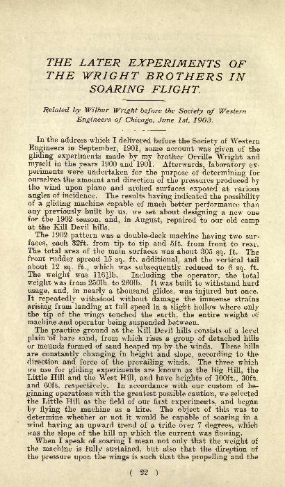
THE LATER EXPERIMENTS OFTHE WRIGHT BROTHERS IN
SOARING FLIGHT.
Related by Wilbur Wright before the Society of Western
Engineers of Chicago, June 1st, 1903.
In the address which I delivered before the Society of WesternEngineers in September, 1901, some account was given of the
gliding experiments made by my brother Orville Wright andmyself in the years 1900 and 1901. Afterwards, laboratory ex-
periments were undertaken for the purpose of determining forourselves the amount and direction of the pressures produced bythe wind upon plane and arched surfaces exposed at various
angles of incidence. The results having indicated the possibilityof a gliding machine capable of much better performance thanany previously built by us, we set about designing a new onefor the 1902 season, and, in August, repaired to our old campat the Kill Devil hills.
The 1902 pattern was a double-deck machine having two sur-
faces, each 32ft. from tip to tip and 5ft. from front to rear.The total area of the main surfaces was about 305 sq. ft. Thefront rudder spread 15 sq. ft. additional, and the vertical tail
about 12 sq. ft., which was subsequently reduced to 6 sq. ft.
The weight was 116^1b. Including the operator, the total
weight was from 2501b. to 2601b. It was built to withstand hard
usage, and, in nearly a thousand glides, was injured but once.It repeatedly withstood without damage the immense strains
arising from landing at full speed in a slight hollow where onlythe tip of the wings touched the earth, the entire weight oi:
machine and operator being suspended between.The practice ground at the Kill Devil hills consists of a level
plain of bare sand, from which rises a group of detached hills
or mounds formed of sand heaped up by the winds. These hills
are constantly changing in height and slope, according to thedirection and force of the prevailing winds. The three whi^hwe use for gliding experiments are known as the Big Hill, theLittle Hill and the West Hill, and have heights of 100ft., 30ft.
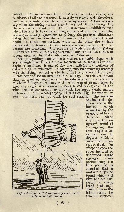
and 60ft. respectively. In accordance with our custom of be-
ginning operations with the greatest possible caution, we selectedthe Little Hill as the field of our first experiments, and beganby flying the machine as a kite. The object of this was todetermine whether or not it would be capable of soaring in a
wind having an upward trend of a trifle over 7 degrees, whichwas the slope of the hill up which the current was flowing.When I speak of soaring I mean not only that the weight of
the machine is fully sustained, but also that the direction of
the pressure upon the wings is such that the propelling and the
( 22 )
retarding forces are exactly in balance; in other words, theresultant of all the pressures is exactly vertical, and, therefore,without any unbalanced horizontal component. A kite is soar-
ing when the string stands exactly vertical, this showing that
there is no backward pull. The phenomenon is exhibited onlywhen the kite is flown in a rising current of air. In principle,
soaring is exactly equivalent to gliding, the practical difference
being that in one case the wind moves with an upward trend
against a motionless surface, while in the other the surface
moves with a downward trend against motionless air. The re-
actions are identical. The soaring of birds consists in glidingdownwards through a rising current of air, which has a rate of
ascent equal to the bird's relative rate of descent.
Testing a gliding machine as a kite on a suitable slope, with
just enough wind to sustain the machine at its most favourable
angle of incidence, is one of the most satisfactory methods of"
determining its efficiency. In soaring, the kite must fly steadilywith the string vertical or a little to the front. Merely darting upto this position for an instant is not soaring. On trial, we foundthat the machine would soar on the side of a hill having a slopeof about 7 degrees, whenever the wind was of proper force to
keep the angle of incidence between 4 and 8 degrees. If the
wind became too strong or too weak the ropes would incline
to leeward. The accompanying illustration (Fig. 14) was taken
when the wind was too weak for real soaring. The surfaces
are inclined 4 de-
grees above the
horizon, whichis marked by the
ocean level in thedistance. Since
the wind had an
upward trend of
7 degrees, thetotal angle of in-
cidence was 11
degrees, which is
outside the limits
specified. Onsteeper slopes the
ropes inclined to
windward quite
strongly. In ex-
perimenting o nthis plan it is
essential that auniform slope befound which will
give the air cur-
r e n t a risingtrend just suffi-
cient to cause the
Fig. 14. The 1902 machine flown as a kite string tokite in a light wind. stand vertical.
Then, both gravity and the pull on the string, which togetherprovide the force counteracting the wind pressure on the sur-
faces, are applied in a single direction. It is, therefore, notmaterial what proportion of the total counteracting force is
due to each of the several components, nor even what is their
total amount, because the experiment is exclusively for the pur-pose of determining the direction of the pressure on the surfaces
by observing the direction of the reaction. When the kite stringinclines to windward the slope is too steep ;
if to leeward, not
steep enough. But it is not advisable to attempt to determinehow much the slope varies from the proper amount by observingthe angle of the string from the vertical, for, when the pull of
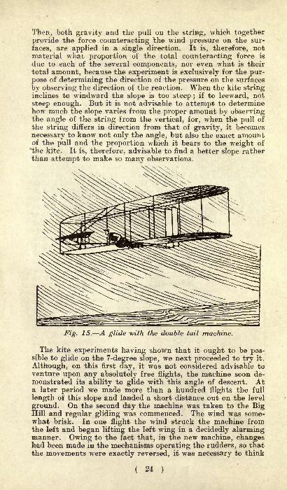
the string differs in direction from that of gravity, it becomes
necessary to know not only the angle, but also the exact amountof the pull and the proportion which it bears to the weight of
the kite. It is, therefore, advisable to find a better slope ratherthan attempt to make so many observations.
Fig. 15. A glide with the double tail machine.
The kite experiments having shown that it ought to be pos-sible to glide on the 7-degree slope, we next proceeded to try it.
Although, on this first day, it was not considered advisable toventure upon any absolutely free flights, the machine soon de-monstrated its ability to glide with this angle of descent. Ata later period we made more than a hundred flights the full
length of this slope and landed a short distance out on the level
ground. On the second day the machine was taken to the BigHill and regular gliding was commenced. The wind was some-what brisk. In one flight the wind struck the machine fromthe left and began lifting the left wing in a decidedly alarmingmanner. Owing to the fact that, in the new machine, changeshad been made in the mechanisms operating the rudders, so thatthe movements were exactly reversed, it was necessary to think
( 24 )
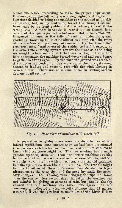
a moment before proceeding to make the proper adjustment.But meanwhile the left wing was rising higher and higher. I
therefore decided to bring the machine to the ground as quicklyas possible, but, in my confusion, forgot the change that hadbeen made in the front rudder, and instinctively turned it the
wrong way. Almost instantly it reared up as though benton a mad attempt to pierce the heavens. But, after a moment,it seemed to perceive the folly of such an undertaking and
gradually slowed up till it came almost to a stop with the front
of the machine still pointing heavenward. By this time I hadrecovered myself and reversed the rudder to its full extent, at
the same time climbing upward toward the front so as to bringmy weight to bear on the part that was too high. Under this
heroic treatment the machine turned downward and soon beganto gather headway again. By the time the ground was reached,it was under fair control, but, as one wing touched first, it swungaround in landing and came to rest with the wind blowing in
from the rear. There was no unusual shock in landing and no
damage at all resulted.
Fig. 16. Rear view of machine with single tail.
In several other glides there were the disturbances of the
lateral equilibrium more marked than we had been accustomedto experience with the former machines, and we were at a loss to
know what the cause might be. The new machine had a muchgreater tip-to-tip dimension than our former machines
;it also
had a vertical tail, while the earlier ones were tailless, and the
wing tips were on a line with the centre, while the old machineshad the tips drawn down like a gull's wings. The trouble mightbe due to either of these differences. We decided to beginalterations at the wing tips, and the next day made the neces-
sary changes in the trussing, thus bringing the tips Gin. lowerthan the centre. For several days thereafter the Aveather wasnot suitable for gliding on account of rain, but, finally, the skycleared and the machine was taken out again. As theanemometer indicated a wind velocity of more than 11 metresa second, it was thought best to make use of the Little Hill in
( 25 )

testing the effect of the changes that had been made. But laterin the day, when the velocity fell to about nine metres a second,the Big Hill was tried again.On this day my brother Orville did most of the gliding. After
a few preliminary flights, to accustom himself to the newmethod of operating the front rudder, he felt himself ready toundertake the management of the lateral control also. Shortlyafterwards he started on a flight with one wing slightly higherthan the other. This caused the machine to veer to the left.
He waited a moment to see whether it would right itself, butfinding that it did not, then decided to apply the control. Atthe very instant he did this, however, the right wing most un-
expectedly rose much higher than before and led him to thinkthat possibly he had made a mistake. A moment of thoughtwas required to assure himself that he had made the rightmotion, and another to increase the movement. Meanwhile hehad neglected the front rudder, by which the fore-and-aftbalance was maintained. The machine turned up in front moreand more till it assumed a most dangerous attitude. We whowere on the ground noticed this in advance of the aviator, whowas thoroughly absorbed in the attempt to restore the lateral
balance, but our shouts of alarm were drowned by the howlingof the wind. It was only when the machine came to a stop andstarted backward that he at length realised the true situation.
From the height of nearly 30ft. the machine sailed diagonallybackward till it struck the ground. The unlucky aeronaut hadtime for one hasty glance behind him and the next instantfound himself the centre of a mass of fluttering wreckage. Howhe escaped injury I do not know, but, afterwards, he was unableto show a scratch or bruise anywhere, though his clothes weretorn in one place. This little misadventure, which occurredalmost at the very beginning of our practice with the newmachine, was the only thing approaching an accident that hap-pened during these experiments, and was the only occasion onwhich the machine suffered any injury. The latter was made as
good as new by a few days' labour, and was not again broken in
any of the many hundred glides which we subsequently madewith it.
By long practice the management of a flying machine shouldbecome as instinctive as the balancing movements a man un-
consciously employs with every step in walking, but, in the earlydays, it is easy to make blunders. For the purpose of reducingthe danger to the lowest possible point we usually kept close tothe ground. Often, a glide of several hundred feet would bemade at a height of a few feet or even a few inches sometimes.It was the aim to avoid unnecessary risk. While the high flightswere more spectacular, the low ones were fully as valuable for
training purposes. Skill comes by the constant repetition of
familiar feats rather than by a few over-bold attempts at feats
for which the performer is yet poorly prepared.It had been noticed during the day that, when a side gust
struck the machine, its effect was at first partly counteracted
by the vertical tail, but, after a time, when the machine had
acquired a lateral motion, the tail made matters worse instead
( 26 )
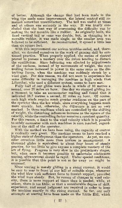
of better. Although the change that had been made in the
wing tips made some improvement, the lateral control still re-
mained somewhat unsatisfactory. The tail was useful at times
and at others was seriously in the way. It was finally con-
cluded that the best way of overcoming the difficulty was by'
making the tail movable like a rudder. As originally built, the
fixed vertical tail or vane was double, but, in changing to amovable rudder, it was made single, as the smaller area wasbelieved to be sufficient. As reconstructed, it spread a little less
than six square feet.
With this improvement our serious troubles ended, and, there-
after, we devoted ourselves to the work of gaining skill by con-
tinued practice. When properly applied, the means of control
proved to possess a mastery over the forces tending to disturbthe equilibrium. Since balancing was eifected by adjustmentsof the surfaces, instead of by movements of weight, the con-
trolling forces increased in power in the same ratio as the dis-
turbing forces, when the machine was suddenly struck by awind gust. For this reason, we did not seem to experience thesame difficulty in managing the machine in high winds that
Lilienthal, who used a different system, seems to have met.
Fully half of our glides were made in winds of 10 metres a
second, over 20 miles an hour. One day we stopped gliding for
a moment to take an anemometer reading and found that it
indicated 16.7 metres a second, 37 miles an hour. Of course,such high winds require much greater readiness on the part of
the operator than the low winds, since everything happens muchmore quickly, but, otherwise, the difference is not so verymarked. In those machines which are controlled by the shiftingof weight, the disturbing influences increase as the square of the
velocity, while the controlling factor remains a constant quantity.For this reason, a limit to the wind velocity which it is possibleto safely encounter with such machines is soon reached, regard-less of the skill of the operator.With the method we have been using, the capacity of control
is evidently very great. The machine seems to have reached a
higher state of development than the operators. As yet, we con-sider ourselves little more than novices in management. Athousand glides is equivalent to about four hours of steadypractice, far too little to give anyone a complete mastery of theart of flying. Progress is very slow in the preliminary stages,but, when once it becomes possible to undertake continuous
soaring, advancement should be rapid. Under special conditions,it is possible that this point is not so far away as might be
supposed.Since soaring is merely gliding in a rising current, it would
be easy to soar in front of any hill of suitable slope, wheneverthe wind blew with sufficient force to furnish support, providedthe wind were steady. But, by reason of changes in wind velo-
city, there is more support at times than is needed, while, at
others, there is too little, so that a considerable degree of skill,
experience, and sound judgment are required in order to keepthe machine exactly in the rising current. So far, our onlyattempts at soaring have been made on the Little Hill, which
( 27 ).
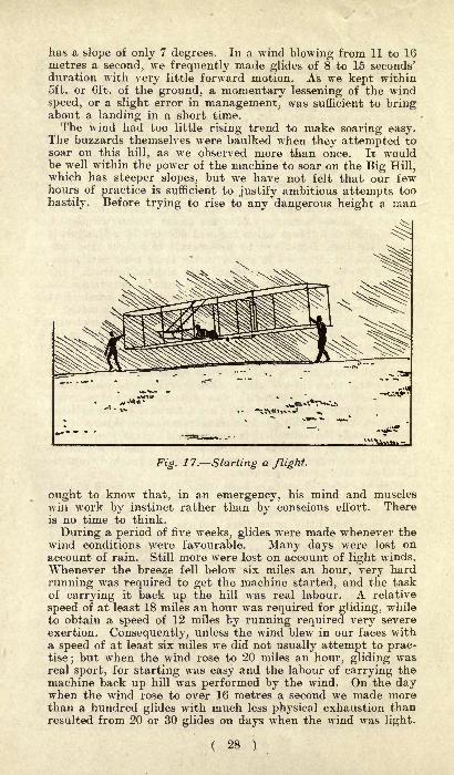
has a slope of only 7 degrees. In a wind blowing from 11 to 16metres a second, we frequently made glides of 8 to 15 seconds'duration with very little forward motion. As we kept within5ft. or 6ft. of the ground, a momentary lessening of the wind
speed, or a slight error in management, was sufficient to bringabout a landing in a short time.The wind had too little rising trend to make soaring easy.
The buzzards themselves were baulked when they attempted tosoar on this hill, as we observed more than oiice. It wouldbe well within the power of the machine to soar on the Big Hill,which has steeper slopes, but we have not felt that our fewhours of practice is sufficient to justify ambitious attempts too
hastily. Before trying to rise to any dangerous height a man
*.<*5i
Fig. 1 7. Starting a flight.
ought to know that, in an emergency, his mind and muscleswin work by instinct rather than by conscious effort. Thereis no time to think.
During a period of five weeks, glides were made whenever thewind conditions were favourable. Many days were lost onaccount of rain. Still more were lost on account of light winds.
Whenever the breeze fell below six miles an hour, very hard
running was required to get the machine started, and the taskof carrying it back up the hill was real labour. A relative
speed of at least 18 miles an hour was required for gliding, whileto obtain a speed of 12 miles by running required very severe
exertion. Consequently, unless the wind blew in our faces witha speed of at least six miles we did not usually attempt to prac-tise; but when the wind rose to 20 miles an hour, gliding wasreal sport, for starting was easy and the labour of carrying themachine back up hill was performed by the wind. On the daywhen the wind rose to over 16 metres a second we made morethan a hundred glides with much less physical exhaustion thanresulted from 20 or 30 glides on days when the wind was light.
( 28 )

Xo complete record was kept of all the glides made duringthe season. In the last six days of experiment, we made morethan 375, but these included our very best days. The total
number for the season was probably between 700 and 1,000. The
longest glide was 622^ft., and the time 26sec.
The prime object in these experiments was to obtain practicein the management of a man-carrying machine, but an object of
scarcely less importance was to obtain data for the study of thescientific problems involved in flight. Observations wrere almost
constantly being made for the purpose of determining theamount and direction of the pressures upon the sustaining wings ;
the minimum speed required for support ;the speed and angle
of incidence at which the horizontal resistance became least;
and the minimum angle of descent at which it was possible to
glide.To determine any of these points with exactness was found
to be very difficult indeed, but by careful observations undertest conditions it was possible to obtain reasonably close approxi-mations. It was found that a speed of about 16 miles an hourwould produce a pressure sufficient to support machine andoperator, but the angle of incidence was too great for generalgliding purposes. At 18 miles, the angle of incidence was about8 degrees, and the machine would glide on the Little Hill, de-
scending at an angle of a little over 7 degrees. Although the wing&
Fig. 18. Making a turn to the right.
were inclined slightly above the horizon, the machine continuedto glide without loss of velocity. With a speed of 22 miles an
hour, the angle of incidence required for support was 4 or 5degrees, and the angle of descent a little less than 7 degrees.At this speed, the surfaces were inclined several degrees belowthe horizon. As the speed became greater, the angle of incidencecontinued to grow less, but the angle of descent became greateragain, thus showing that the point of minimum resistance hadbeen passed. Scores of glides were made at angles of descentunder 6 degrees, and, in a few cases, we reached 5 degrees. Onthe last day of experiment, we made a few attempts at records.A line was drawn a short distance up the slope as a starting
( 29 )
mark, and four trials were made. Twice the machine landed onthe same spot. The distance was 156^ft., and the angle of
descent exactly 5 degrees. Time, 6^sec. From a point higher upthe slope, the best angle was 5 degrees and 25min. for a glideof 225ft. Time, lO^sec.
The wind was blowing about nine miles
an hour. The glides were made directly to windward and
straight down the slope. Taking 7 degrees as a conservative
estimate of the normal angle of descent, the horizontal resist-
ance of the machine was 301b., as computed by multiplying thetotal weight, 2501b., by the tangent of the angle of descent.
This resistance remained nearly constant at speeds between 18
and 25 miles an hour. Above or below these limits, there wasa somewhat rapid increase. At 18 miles, the power consumedwas l^h.p. ;
at 25 miles, 2h.p. At the lower speed, 1661b. weresustained for each horse-power consumed; at the higher speed,1251b. per horse-power. Between 18 and 25 miles, the horse-
power increased almost in exact ratio in the increase in speed,but above or below these limits the power increased rapidly, andwith a constantly accelerating ratio.
On two occasions we observed a phenomenon whose naturewe were not able to determine with certainty. One day mybrother noticed, in several glides, a peculiar tapping, as if somepart of the machine were loose and flapping. Careful examina-tion failed to disclose anything about the machine which could
possibly cause it. Some weeks later, while I was making a
glide, the same peculiar tapping began again in the midst of awind gust. It felt like little waves striking the bottom of aflat-bottomed row-boat. While I was wondering what thecause could be, the machine suddenly, but without any notice-
able change in its inclination to the horizon, dropped a distanceof nearly 10ft., and in the twinkling of an eye was flat on the
ground. I am certain that the gust went out with a downwardtrend, which struck the surfaces on the upper side. The descentwas at first more rapid than that due to gravity, for my bodyapparently rose off the machine till only my hands and feet
touched it. Toward the end the descent was slower. It maybe that the tapping was caused by the wind rapidly strikingthe surfaces alternately on the upper and the lower sides. It is arule almost universal that gusts come on with a rising trendand die out with a descending trend, but, on these particularoccasions, there must have been a most unusual turmoil duringthe continuance of the gust which would have exhibited a veryinteresting spectacle had it been visible to the eye.
Irregularities of the wind are most noticeable when the windis high, on account of the greater power then exhibited, but
light winds show almost equal relative variations. An aviator
must expect to encounter in every flight variations in velocity,in direction, and in upward or downward trend. And these
variations not only give rise to those disturbances of the equi-librium which result from the travel of the centre of pressuredue to the changed angle of incidence, but also, by reason of
the fact that the wind changes do not occur simultaneously or
uniformly over the entire machine, give rise to a second series
of disturbances of even more troublesome character. Thus, a
( 30 )

gust coming on very suddenly will strike the front of the
machine and throw it up before the back part is acted upon at
all. Or the right wing may encounter a wind of very different
velocity and trend from the left wing and the machine will tend
to turn over sideways. The problem of overcoming these dis-
turbances by automatic means has engaged the attention of
many very ingenious minds, but, to my brother and myself, it
has seemed preferable to depend entirely on intelligent control.
In all of ourmachines themaintenance of
the equilibriumhas been depen-dent on the skill
and constant
vigilarfce of theaviators.
In addition to
the work withthe machine wealso mademany observa-t i o n s on the
flight of soaring& 19. Skimming the ground.
birds, which were
very abundant in the vicinity of our camp. Bald eagles, ospreys,
hawks, and buzzards gave us daily exhibitions of their powers.The buzzards were the most numerous and were the most per-sistent soarers. They apparently never napped except when it
was absolutely necessary, while the eagles and hawks usuallysoared only when they were at leisure. Two methods of soaringwere employed. When the weather was cold and damp andthe wind strong, the buzzards would be seen soaring back andforth along the hills, or at the edge of a clump of trees. Theywere evidently taking advantage of the current of air flowing
upward over these obstructions. On such days they were often
utterly unable to soar, except in these special places. But on
warm, clear days, when the wind was light, they would beseen high in the air soaring in great circles. Usually, however,it seemed to be necessary to reach a height of several hundredfeet by flapping before this style of soaring became possible.
Frequently a great number of them would begin circling in
one spot, rising together higher and higher till finally theywould disperse, each gliding off in Avhatever direction it wishedto go. At such times other buzzards only a short distance
away found it necessary to flap frequently in order to maintainthemselves. But when they reached a point beneath the
circling flock, they began to rise on motionless wings. This
seemed to indicate that rising columns of air do not exist every-
where, but that the birds must find them. They evidentlywatch each other, and when one finds a rising current the
others quickly make their way to it. One day, when scarce a
breath of wind was stirring on the ground, we noticed two bald
eagles sailing in circling sweeps at a height of probably 500ft.
31 )
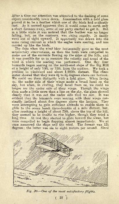
After a time our attention was attracted to the Hashing of someobject considerably lower down. Examination with a held glassproved it to be a feather which one of the birds had evidentlycast. As it seemed apparent that it would come to earth onlya short distance away, some of our party started to get it. Butin a little while it was noticed that the feather was no longerfalling, but, on the contrary, was rising rapidly. It finallywent out of sight upward. It apparently was drawn into thesame rising current in which the eagles were soaring, and wascarried up like the birds.
The days w^hen the wind blew horizontally gave us the most
satisfactory observations, as then the birds were compelled tomake use of the currents flowing up the sides of the hills, andit was possible for us to measure the velocity and trend of thewind in which the soaring was performed. One day fourbuzzards began soaring on the north-east slope of the Big Hill
at a height of only 10ft. or 12ft. from the surface. We took a
position to windward and about 1,200ft. distant. The clino-
meter showed that they were 4^ to 5^ degrees above our horizon.
We could see them distinctly with a field glass. When facingus, the under side of their wings made a broad band on the
sky, but when, in circling, they faced from us, we could no
longer see the under side of their \vings. Though the wingsthen made a little more than a line on the sky, the glass showed
clearly that it was not the under side that we saw. It wasevident that the buzzards were soaring with their wings con-
stantly inclined about five degrees above the horizon. Theywere attempting to gain sufficient altitude to enable them to
glide to the ocean beach three-fourths of a mile distant, but,after reaching a height of about 75ft. above the top of the hill,
they seemed to be unable to rise higher, though they tried a
long time. At last they started to glide toward the ocean, butwere compelled to begin flapping almost immediately. We at
once measured the slope and the wind. The former was 12|degrees ;
the latter was six to eight metres per second. Since
Fig. 20. One of the most satisfactory flights.
( 32 ')

tne wings were inclined five degrees above the horizon and thewind had a rising trend of tuny 12 degrees, the angle of inci-
dence was about 17 degrees. The wind did not average morethan seven metres 15 miles an hour. For the most part thebirds faced the wind steadily, but in the hills they were com-
pelled to circle or glide back and forth, in order to obtain speedsufficient to provide support. As the buzzard weighs about .81b.
per square foot of wing area, the lifting power of the wind at
17 degrees angle of incidence was apparently as great as it
would have been had it been blowing straight upward with equalvelocity. The pressure was inclined five degrees in front of
the normal, and the angle of the descent was 12^ degrees.On another day I stood on top of the West Hill, directly
behind a buzzard which was soaring on the steep southern
slope. It was just on a level with my eye and not more than75ft. distant. For some time it remained almost motionless.
Although the wings were inclined about five degrees above the
horizon, it was not driven backward by the wind. This bird is
specially adapted to soaring at large angles of incidence in
strongly-rising currents. Its wings are deeply curved. Unlessthe upward trend amounts to at least eight degrees, it seemsto be unable to maintain itself. One day we watched a flock
attempting to soar on the west slope of the Big Hill, whichhas a descent of nearly nine degrees. The birds would start
near the top and glide down along the slope very much as wedid with the machine, but we noticed that whenever theyglided parallel with the slope their speed diminished, and whentheir speed was maintained the angle of descent was greaterthan that of the hill. In every case they found it necessaryto flap before they had gone 200ft. They tried time and again,but always with the same results. Finally, they resorted to
hard flapping until a height of about 150ft. above the top of thehill was reached, after which they were able to soar in circles
without difficulty.On another day they finally succeeded in rising on almost the
same slope, from which it was concluded that the buzzards' best
angle of descent could not be far from eight degrees. Thereis no question in my mind that men can build wings havingas little as, or less relative resistance than, that of the best
soaring birds.
The bird's wings are undoubtedly very well designed indeed,but it is not any extraordinary efficiency that strikes with
astonishment, but rather the marvellous skill with which theyare used. It is true that I have seen birds perform soaringfeats of almost incredible nature in positions where it was not
possible to measure the speed and trend of the wind, but when-ever it was possible to determine, by actual measurement, theconditions under which the soaring was performed, it was easyto account for it on the basis of the results obtained withartificial wings. The soaring problem is apparently not so
much one of better wings as of better operators.
( 33 )
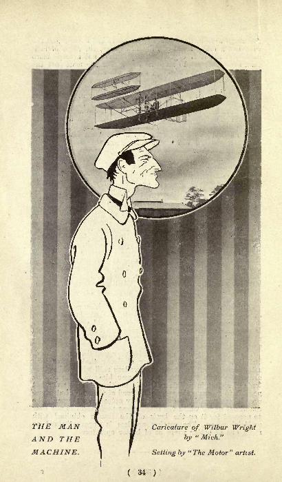
THE MANAND THEMACHINE.
Caricature of Wilbur Wright
by" Mich."
Setting by "The Motor" artist.
( 34 )
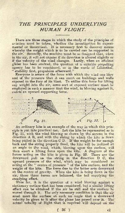
THE PRINCIPLES UNDERLYINGHUMAN FLIGHT.
There are three stages in which the study of the principles of
aviation must be taken, whether the investigation be experi-mental or theoretical. It is necessary first to discover means
whereby the weight which is to be carried can be supported in
the air. Secondly, the machine must be so designed that, whenin the air, it will not capsize if its direction is altered slightly or
if the velocity of the wind changes. Lastly, when an efficient
glider has been evolved, the question of a suitable propellingagency has to be considered, or in the words of Lilienthal,"stability first, propulsion afterward."
Everyone is aware of the force with which the wind can blowand of the pressure that it can exert on buildings and walls
exposed to the fury of its blast. To utilise this force for lifting
any weight into the air, some sort of exposed surface must be
employed in such a manner that the wind, in blowing against it,
exerts an upward supporting force.
An ordinary kite is an example of the way in which this prin-
ciple is put into practical use. Let the kite be represented as in
Fig. 21, with the wind blowing as shown by the arrows in thedirection A B, and with the string by which the kite is flown
being pulled in the direction CD. If the weight be far enoughback and the string properly fixed, the kite will be inclined atan angle to the wind, which, blowing upon- the surface, will
then exert a lifting force upon the kite. A diagram of theforces acting on the kite is given in Fig. 22. There are thedownward pull on the string in the direction D C, the
upward pressure of the wind, which may be considered as
acting at the " centre of pressure"
of the kite surface, and the
weight of the kite. The force due to the latter acts downwardat the centre of gravity. When the kite is being flown in the
air, these three forces are balanced, the tail supplying the
steadying effect.
Thus far, it is the question of a wind blowing against a
stationary surface that has been considered, but a similar liftingeffect can be obtained if the air be still and the surface bemoved through it. The only necessary condition is that the air
must meet the surface at such an angle that a downwardvelocity be given to it after the plane has passed over it. Theactual velocity of flight that is required will depend on ;the
( 35 ) c2
amount of weight that has to be carried, and on the supportingsurface that is used. The greater the weight or the less the
surface, the greater must be the speed of the machine, and vice
versa.
Just as in flying a kite in the air a considerable pull must be
exerted on the string by which it is flown, so in an aeroplane or
glider which is in flight there must be a force exerted to push it
through the air. This force has to overcome the resistance
caused by pushing the framework, etc., of the machine throughthe air, and is similar in effect to that which has to be exerted
to drive a car at high speeds. It is usually termed the "drift,"
as distinguished from the upward or lifting force called the"
lift." Both lift and drift will vary considerably with different
types of machines, with the loads carried, and with the speedsof flight. If, however, the area of supporting surface and the
weight that has to be carried both be limited, it is evident that,
by trying all manner of shapes of plane with varying cross-
sections and thicknesses, different values for the drift will be
obtained, supposing that in each case the area were sufficient to
support the weight. The most efficient shape would be that re-
quiring the least force to push it through the air, that is it
would have the least drift. For this plane the ratio of lift/drift
would be the highest.The aim in designing an aeroplane is to make this value as
high as possible, provided that it does not involve a very high
speed of flight, it 'is well to investigate the factors on which
the efficiency depends.If one could see the air as the plane meets it when gliding, it
would be apparent that the air does not flow closely round the
contour of the plane but forms a " dead water "region at the
back of the plane. With the plane inclined at a large angle the
effect is much more pronounced, usually resulting in turbu-
lence, i.e., a churning up of the air all round the surface of the
plane. This turbulent effect requires energy to set it in motion,so that if one obtains a certain lift with a plane the drift will
be much less if the turbulence can be eliminated. This is
effected by making the cross-section of the planes such that it is
of" stream line
"form, so that the air flows evenly around with
a minimum disturbance.
The pioneer work in the experimental investigation of the best
form to be used for plane cross-section was carried out byHoratio Phillips, whose dipping front edge forms are treated in
a separate chapter in the book.
Phillips also advocates the use of wood for plane surfaces,because it forms a hard polished surface, offering much less
resistance than a surface formed of canvas stretched over a
frame. For Phillips' s machine (described on page 46) wood was,no doubt, the best substance, but, for the modern aeroplane,its weight would, probably, be excessive.
In addition to the cross-section of the planes there is still the
plan form to be considered, and this, too, has a considerable
effect on the efficiency. The ratio of the spread of the planes to
the fore and aft depth is usually termed the "aspect ratio
" of
the plane. It has been found experimentally, with a plane in
( 36 )
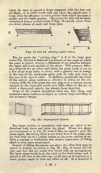
which the span or spread is large compared with the fore and
aft depth, or in other words with one where the aspect ratio is
large, that the efficiency is much greater than where the span is
smaller and the depth greater. The reason for this will be easily
understood from a consideration of Figs. 23 and 24, where there
are shown planes of small and large span.
<s
(b)
A
Figs. 23 and 24, showing aspect ratios.
The air meets the "cutting edge
" A B of the large spanplane (Fig. 23) and is deflected downwards at the angle at whichthe plane is placed, causing a difference of air pressure betweenthe upper and lower surface of the plane. This pressure differ-
ence between the air above and below the plane tends to set upa flow of air from below to above, with a greater loss of energyin the case of the small-span plane with its wide ends than in
the case of the narrow plane. In addition, practically the wholeof the narrow plane surfaces is effective in acting on the air,
whereas with the wide plane the rear edge is to a certain extent
shielded by the front and exerts very little effect on the air, to
which a downward velocity has already been imparted.Many of the modern aeroplanes have one, two, three, and
sometimes more surfaces arranged in various ways according to
the inventor's design.
Fig. 25. Superposed biplane.
The single surface or monoplane acts upon air which is un-
disturbed both above and below the plane. Where two planesare superposed as in Fig. 25, even if they be spaced a good dis-
tance apart, the lifting effect is not twice that of the single one,for they both act to a certain extent on the same cushion of air.
With a triplane or multiplane this relative diminution of lifting
effort is even more pronounced.Instead of fitting the planes one above the other they may be
placed in tandem, as shown in Fig. 26. Fig. 27 shows the endview and how the air would flow round such an arrangement.The back plane would be in the wash of the front plane, and, if
placed at all close to the first one, would have to be inclined at a
much greater angle to have any effect at all. It is doubtful if
( 37 )
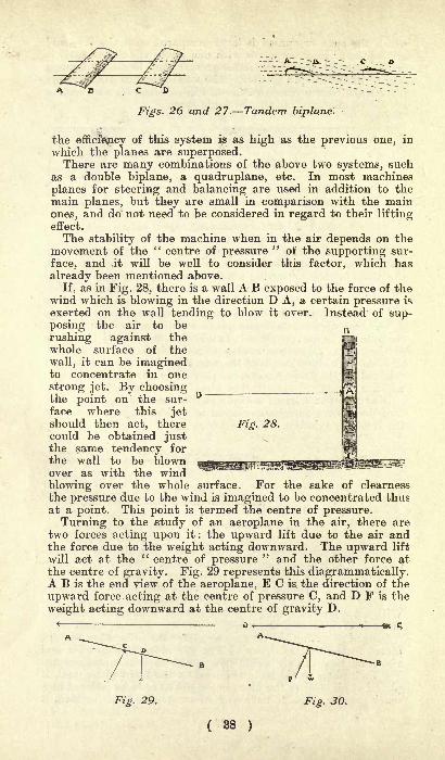
CD ---~ - --
Figs. 26 and 27. Tandem biplane.
the efficiency of this system is as high as the previous one, in
which the planes are superposed.There are many combinations of the above two systems, such
as a double biplane, a quadruplane, etc. In most machines
planes for steering and balancing are used in addition to themain planes, but they are small in comparison with the mainones, and do not need to be considered in regard to their liftingeffect.
The stability of the machine when in the air depends on themovement of the " centre of pressure
"of the supporting sur-
face, and .it will be well to consider this factor, which has
already been mentioned above.
If, as in Fig. 28, there is a wall A B exposed to the force of thewind which is blowing in the direction D A, a certain pressure is
exerted on the wall tending to blow it over. Instead of sup-posing the air to be
rushing against thewhole surface of the
wall, it can be imaginedto concentrate in one
strong jet. By choosingthe point on the sur-
face where this jetshould then act, therecould be obtained justthe same tendency for
the wall to be blownover as with the wind
blowing over the whole surface. For the sake of clearness
the pressure due to the wind is imagined to be concentrated thusat a point. This point is termed the centre of pressure.
Turning to the study of an aeroplane in the air, there aretwo forces acting upon it: the upward lift due to the air andthe force due to the weight acting downward. The upward lift
will act at the " centre of pressure" and the other force at
the centre of gravity. Fig. 29 represents this diagrammatically.A B is the end view of the aeroplane, E C is the direction of the
upward force. acting at the centre of pressure C, and D F is the
weight acting downward at the centre of gravity D.
-m C
Fig. 29. Fig. 30.
( 38 )

Neglecting the question of propulsion for the moment, these
are the only two forces that need be considered, and if they are
balanced there will be no tendency for the machine to capsize.As shown in Fig. 29, the centre of pressure is ahead of the centre
of gravity, and if this state of affairs were allowed to continue
the front of the machine would tip right over. Some meansmust therefore be employed whereby if the machine is balancedwhen the aeroplane is inclined at a certain angle, the aeroplanewill come back to the correct angle if the latter is altered.
There are two ways of effecting this, one being by hand control
as in the Wright machine and the other being more or less auto-
matic.In the Wright machine the tips of the planes are flexible and
their angle of incidence to the air can be altered by a controllingdevice operated by the aeronaut. This, in conjunction with the
rudders, is continually in operation by the aviator, so that thecentre of pressure of the planes is made always to coincide withthe centre of gravity.
Fig. 31. Fig. 32.
I
Automatic stability depends for its action upon the move-ment of the position of the centre of pressure when the angleof incidence varies.* It is found that, as the angle of incidence
decreases, the position of the centre of pressure moves forwardtowards the front edge of the plane, and vice versa. This doesnot hold good for one or two shapes of planes if the angle is
less than 10 degrees, as will be explained later. When the
angle of incidence increases, the reverse takes place, the centreof pressure moving backward away from the front edge.Let it be supposed that there is a plane A B (see Fig. 30)
moving through the air in the direction C D shown by the arrow.Let it also be supposed that the whole arrangement is balancedfor the speed at which it is travelling, i.e., the positions of thecentres of pressure and gravity coincide. At any moment it is
possible that the speed of the wind may suddenly increase, andat that instant the machine, which will still be travelling at thesame speed relatively to the earth, will meet the air at a
greater velocity. The lifting effect is increased and the noseof the machine will rise in the air. The angle at which thesurface meets the air is now greater and the centre of pressurewill move back to some point (C) as shown in Fig. 31.
From this diagram it will be seen that the force due to the
weight is trying to pull the nose down and the upward pressureis trying to push the tail up. The result is that the angle of
incidence will be altered, until it takes the original value as
indicated in Fig. 30, where the positions of the centres of
pressure and gravity coincide.
The opposite effect is shown in Fig. 32. If a wind were
( 39 )
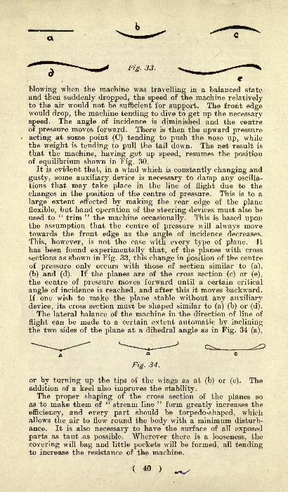
Fig. 33.
blowing when the machine was travelling in a balanced stateand then suddenly dropped, the speed of the machine relativelyto the air would not be sufficient for support. The front edgewould drop, the machine tending to dive to get up the necessaryspeed. The angle of incidence is diminished and the centreof pressure moves forward. There is then the upward pressureacting at some point (C) tending to push the nose up, whilethe weight is tending to pull the tail down. The net result is
that the machine, having got up speed, resumes the positionof equilibrium shown in Fig. 30.
It is evident that, in a wind which is constantly changing and
gusty, some auxiliary device is necessary to damp any oscilla-
tions that may take place in the line of flight due to the
changes in the position of the centre of pressure. This is to a
large extent effected by making the rear edge of the planeflexible, but hand -operation of the steering devices nrnst also beused to " trim " the machine occasionally. This is based uponthe assumption that the centre of pressure will always movetowards the front edge as the angle of incidence decreases.
This, however, is not the case with every type of plane. It
has been found experimentally that, of the planes with cross
sections as shown in Fig. 33, this change in position of the centreof pressure only occurs with those of section similar to (a),
(b) and (d). If the planes are of the cross section (c) or (e),
the centre of pressure moves forward until a certain critical
angle of incidence is reached, and after this it moves backward.If one wish to make the plane stable without any auxiliary
device, its cross section must be shaped similar to (a) (b) or (d).
The lateral balance of the machine in the direction of line of
flight can be made to a certain extent automatic by incliningthe two sides of the plane at a dihedral angle as in Fig. 34 (a),
Fig. 34.
or by turning up the tips of the wings as at (b) or (c). Theaddition of a keel also improves the stability.The proper shaping of the cross section of the planes so
as to make them of" stream line
" form greatly increases the
efficiency, and every part should be torpedo-shaped, whichallows the air to flow round the body with a minimum disturb-ance. It is also necessary to have the surface of all exposedparts as taut as possible. Wherever there is a looseness, the
covering will bag and little pockets will be formed, all tendingto increase the resistance of the machine.
( 40 )

BRIEF HISTORY OFTHE AEROPLANE MOVEMENT.
I. Early History.To Leonardo da Vinci, the versatile Italian genius, famed
equally for his work in painting, sculpture, music, architecture,mathematics and physical science, belongs the honour of havingfirst set on paper some rational notions of human flight. Severalremarkable principles are to be found in da Vinci's manuscript.He shows very clearly that he understood the relation betweenthe centre of pressure and the centre of gravity, for he statesthat a bird which finds itself in equilibrium with the centre of
resistance of the wings more forward than the centre of gravitywill descend with the head inclined downwards.
This he wrote after a note on " The kite and other birds whichbeat their wings little, go seeking the course of the wind, andwhen the wind prevails on high, then will they be seen at a
great height, and if it prevails low they will hold themselveslow. When the wind does not prevail at all, then the kite
beats its wings several times in its flight in such a way that it
raises itself high and acquires a start, descending afterwards alittle and progressing without beating its wings, repeating thesame performance time after time."An even clearer exposition of the principles of flight is shown
by his note that the bird that wishes to rise"
will raise its
shoulders so that the air may press between its sides and the
tip of the wings, so that the air will be condensed and will givethe bird the movement towards the ascent and will produce amomentum in the air which will push the bird upward."
- Further, this remarkable genius of the 15th century states
that when, without the help of the wind, the bird remains in
the air without flapping its wings, this shows that the centreof its resistance coincides with its mass centre. In referring to
his classical illustration of a man in a flapping-wing machine,he foresaw that the chief difficulty in gliding or soaring is to
keep the centre of gravity at all times in the right place. Inone of his notes he wrote that the man in the flying machineshould " be free from the waist upwards in order that he mightkeep himself in equilibrium as one does in a boat, so that thecentre of his gravity and that of the apparatus may set itself
in equilibrium and change, when needful, as the centre of re-
sistance changes."Leonardo da Vinci, born in 1452, died in 1519, and there can
be no doubt that this extraordinary man was the first to recog-nise, as he was certainly the first to enunciate, the elementaryprinciples of flight, and he should be given foremost rank in
the annals of aeronautics. The only picture of him which
( 41 )

exists is a peculiar proof of his versatility, the picture havingbeen drawn by himself in red chalk
;it now hangs in the Royal
library at Turin.The Italian master's work is generally prefaced by a reference
to the legends of Dedalus, Icarus and others, which merelyshow how the problem of human flight captivated the imagina-tion of men from the earliest times of which records exist. In
every country, also, the folk-lore is rich in tales of flying men,but in none more than in the Scandinavian countries. Thesetales it is hard to accept as well-founded.
There may, perhaps, be truth in the legend of Simon the
Magician, who during the reign of the Emperor Nero attempted
Fig. 35. A page of early history.
( 42 )
"to rise towards heaven." The legend recounts that Simon
rose in the air"through the assistance of Beelzebub," but that
St. Peter offered up a prayer, the power of the demon wascrushed and the magician fell to earth and was killed by thefall. It is possible that the man used a large plane surfaceand that he discovered, by accident or otherwise, that he couldin that manner be lifted from the earth if he made use of a
rising current of air. In the southern countries the vertical air
currents are very much more frequent than they are in this
country, for which reason the soaring birds are in those regionsfar more common.An English Benedictine monk, Elmerus or Oliver, of Malmes-
bury, appears to have used wings (whether flapping or fixed thetradition does not state), and to have sprung from the topof a tower against the wind. He is said to have actuallyglided for some distance and then to have experienced a sudden
fall, which broke his legs, preventing further experiments.That was in the llth century, and the flight may just as well
have taken place as that of the Saracen who towards the endof the 12th century glided from the top of a tower in Con-
stantinople. The account given in the history of Constanti-
nople by Cousin very clearly describes the apparatus used.
The man was clothed in a white robe, the folds of which werestiffened by willow wands, to serve as sails for the wind.
Evidently he was making use of rigid surfaces in place of the
flapping wings which earlier legends record. In the presenceof the Emperor the Saracen waited until he caught a favourable
wind, and then " rose in the air like a bird," but, like mostof the early investigators of flight, he fell and broke his bones,the accident causing considerable merriment, so the historian
relates.
Towards the end of the 14th century Dante, the Italian
mathematician, is recorded to have flown with artificial wingsover Lake Trasimene. Later he tried to improve upon this ex-
periment by jumping from the top of the highest tower in his
native city of Perugia. He sailed over the crowd in the public
square beneath, and was supported for a long time stationaryin the air, but the iron forging which controlled his left wingis said td have broken and to have been the cause of his un-
checked drop upon the roof of a neighbouring church. Havingbroken one leg in the experiment, he abandoned his efforts to
solve the problem of flying.There is, until the beginning of the 19th century, no further
interesting history to relate, the numerous attempts at flight
that were made in France (especially at the courts of Louis XIV.and Louis XV.) showing no proof of any great genius, all the
investigators of whom those that did not kill themselves were
at least seriously injured being men of ambition who soughtthe favour of the French kings. Most of them used four wings,some operated respectively by the hands and feet, as that of
Besnier.
( 43 )
II- In England : From Cayley to Maxim and Pilcher.
At the commencement of the 19th century there arose anothergreat student of flight, Sir George Cayley, whose writings mightbe read with benefit by many at the present day, for he cer-
tainly had very clear notions of what was required and how it
had to be done.
Sir George Cayley was the first to point out that two planesat a dihedral angle form a basis of stability. For, if themachine heel over, the side which is required to rise gainsresistance by its new position, and that which is required tosink loses it, the operation very much resembling what takes
place in an ordinary boat. In dealing with the principle of
stability in the direction of the path of the machine, he pointedout that experiments showed that in very acute angles withthe current the centre of resistance in a plane does not coincidewith the centre of its surface, but is considerably in front of it.
As the obliquity of the current decreases these centres approachand coincide when the current becomes perpendicular to thesail. Hence, any heel of the machine backward or forwardremoves the centre of support behind or before the point of
suspension, and operates to restore the original position by a
power equal to the whole weight of the machine acting upon alever equal in length to the distance the centre has moved. Torender the machine perfectly steady and to enable it to ascendand descend in its path it becomes necessary, he wrote, to adda rudder in a similar position to the tail in birds.
In 1809 hei made a machine with a surface of 300 sq. ft.,
which was accidentally broken before there was an opportunityof testing the effect of its propelling apparatus. Its steerageand steadiness were perfectly proved, so he relates, and whenany person ran forward with it at full speed, taking advantageof a gentle breeze in front, it would frequently lift him up and
convey him several yards. For his motive power he endeavouredto obtain a steam engine working at a very much higher pres-sure than the couple of pounds per square inch which wasusual in those days, and he also invented a gunpowder engine.It is probable that it was simply owing to the fact that there
was at that time no light prime mover that his experimentsdid not lead him further.
He fully recognised the importance of eliminating every pos-sible rib or strut that could offer any resistance to the air, the
poles that were used in his wings being covered with the cloth
that formed the plane. He was also aware that the shape of
the after part of any body offering resistance to motion throughthe air was of as much importance as that of the front portion.
It is said that some ten years later he succeeded with
mechanical power in raising a man from the ground with his
apparatus, but this has not been properly authenticated.
From that time most of the serious work connected with
human flight in heavier-than-air machines was carried out in
England until Lilienthal made his famous experiments in
Germany.
( 44 )

About 30 years after Sir George Cayley first made public his
researches into the problem of flight there came Henson, whopatented a large aeroplane of canvas, stretched upon a rigidly-trussed frame and propelled by screws operated from a steam
engine. In his patent specification he gave the surface of the
planes as measuring 4,500 sq. ft., that of the tail being1,500 sq. ft. extra, and with a total weight of 3,0001b. he in-
tended to use an engine of 25h.p. His drawings show the mainsurface to have been about 150ft. in spread by about 32ft. in
Fig. 36. Henson's projected aeroplane of 1814.
length, but Henson never completed such a machine. With his
friend, Stringfellow, he completed in 1845 a model of 70 sq. ft.,
weighing just under 301b. It is evident from the accounts of
these experiments that the machine lacked stability and wasnever able to make any flight. Stringfellow later, on his ownaccount, made a much more stable model, which he found wasable to sustain itself in the air in an enclosed space, but notout of doors.
The most important contribution to aeronautical knowledgebefore the modern era of flight commenced was afforded by Mr.
Fig. 37. Phillips's whirling machine for testing the lifting
power of planes.
( 45 )
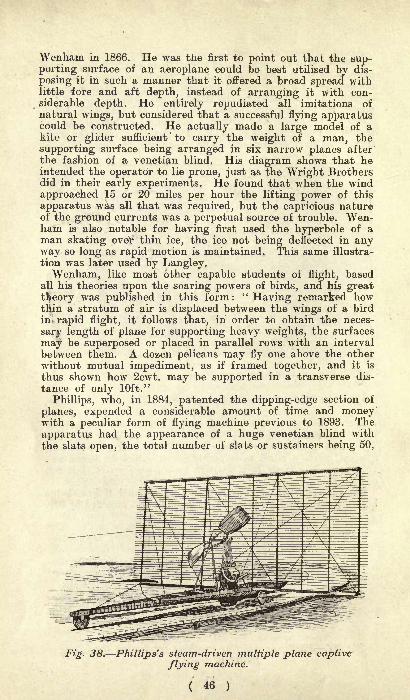
Wenham in 1866. He was the first to point out that the sup-porting surface of an aeroplane could be best utilised by dis-
posing it in such a manner that it offered a broad spread withlittle fore and aft depth, instead of arranging it with con-siderable depth. He entirely repudiated all imitations of
natural wings, but considered that a successful flying apparatuscould be constructed. He actually made a large model of akite or glider sufficient
'
to carry the weight of a man, the
supporting surface being arranged in six narrow planes afterthe fashion of a Venetian blind. His diagram shows that heintended the operator to lie prone, just as the Wright Brothersdid in their early experiments. He found that when the wind
approached 15 or 20 miles per hour the lifting power of this
apparatus was all that was required, but the capricious natureof the ground currents was a perpetual source of trouble. Wen-ham is also notable for having first used the hyperbole of aman skating over thin ice, the ice not being deflected in anyway so long as rapid motion is maintained. This same illustra-
tion was later used by Langley,Wenham, like most other capable students of flight, based
all his theories upon the soaring powers of birds, and his great
theory was published in this form :
' '
Having remarked howtHin a stratum of air is displaced between the wings of a bird
in rapid flight, it follows that, in order to obtain the neces-
sary length of plane for supporting heavy weights, the surfaces
may be superposed or placed in parallel rows with an interval
between them. A dozen pelicans may fly one above the other
without mutual impediment, as if framed together, and it is
thus shown how 2cwt. may be supported in a transverse dis-
tance of only 10ft."
Phillips, who, in 1884, patented the dipping-edge section of
planes, expended a considerable amount of time and moneywith a peculiar form of flying machine previous to 1893. The
apparatus had the appearance of a huge Venetian blind with
the slats open, the total number of slats or sustainers being 50,
Fig. 38. Phillips's steam-driven multiple plane captive
flying machine.
( 46 )
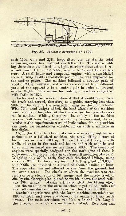
Fig. 39. Maxim's aeroplane of 1893.
each l^in. wide and 22ft. long, fitted 2in. apart; the total
supporting area thus obtained was 136 sq. ft. The frame hold-
ing these slats was fitted on a light carriage mounted on three
wheels, each 1ft. in diameter, one in front and two at therear. - A small boiler and compound engine, with a two-bladedscrew turning at 400 revolutions per minute, was employed for
the motive power. The machine followed a circular path of
wood of 200ft. diameter, and wires were carried from different
parts of the apparatus to a central pole in order to preventerratic flights. This notion for testing a machine originatedwith Tatin in 1879.
The forward wheel was so balanced that it would never leave
the track and served, therefore, as a guide, carrying less than201b. of the weight, the remainder being on the hind wheels.
With 721b. dead weight added, the hind wheels of the machinerose a couple of feet clear of the track when the apparatus wasset in motion. Whilst, therefore, the ability of the machineto raise itself from the ground was amply demonstrated, the netresults of the experiments were of little value, for no provisionwas made for maintaining equilibrium on such a machine in
free flight.About this time Sir Hiram Maxim was carrying out his ex-
periments on a full-sized machine; the total lifting surface of
his apparatus was 6,000 sq. ft., and the total weight with6001b. of water in the tank and boiler, and with naphtha andthree men on board was no less than 8,0001b. Two compoundengines were specially designed for the work (one of these is
to be seen at the present day in the South Kensington Museum).Weighing only 3101b. each, they each developed ISOh.p., usingsteam at 3201b. to the square inch. A lifting effect of 3,0001b.to 4,0001b. was obtained at a speed of about 40 miles an hour.The apparatus was not allowed to rise from the ground, butran over a track. The wheels on which the machine was car-
ried ran over steel rails of 9ft. gauge, and the safety track of
3in. by 9in. Georgia pine, placed about 2ft. above the steel rails,
was 30ft. gauge. Maxim calculated .that the lifting effect
upon the machine on the occasion when it got off the rails andwas badly smashed could not have been less than 10,0001b.Maxim's experiments with the large machine extended from
1890 to 1893, and were abandoned only owing to their costlynature. The main aeroplane was 50ft. wide and 47ft. long in
the direction in Avhich the machine travelled. Five long and
( 47 )

narrow aeroplanes projected from each side. Those that wereattached to the sides of the main aeroplane were 27ft. long,the total width of the machine thus being 104ft. The machinewas also provided with a forward and an after rudder made onthe same general plan as the main aeroplane.Lawrence Hargraves, the inventor of the well-known cellu-
lar or box kite, was for some years engaged upon the subjectof mechanical flight, and in 1892 he constructed a very suc-cessful model. He employed at first compressed air, but later
adopted steam. The general idea of the model was that twofixed wings were carried at a very obtuse angle on the mainkeel, while in front were two flapping wings, which afforded
the propelling power. The wings were driven by a little engine.One of the models, when compressed air was used, flew 343ft.
in 23 seconds. These experiments were apparently discontinued.
A clever young engineer, Pilcher by name, commenced in
1895 to work on LilienthaPs system. His first glider, withwhich he made many flights between 50ft. and 350ft. in length,
weighed 501b. and gave a sustaining surface of 150 sq. ft. Alarger machine, double-decked, which he constructed in the
following year, he found difficult to control. A third andsomewhat lighter machine in 1896 made many good flights.It was equipped with wheels for grounding. In gentle windshis method was to rise into the air like a kite, the glider for
this purpose being towed by a horse, the tow rope passing overa pulley block which made the glider travel five times as fast
as the horse. At any desired altitude, Pilcher cast off and
glided to earth. He designed in 1899 an aeroplane to be driven
by a 4h.p. petrol motor of his own design, but a rib of one of
the wings of his glider broke during a trial in the same year,and falling from a height of 30ft., he broke his collar-bone andsuccumbed within 24 hours.
Fig. 40. Pilcher making a gliding flight in 1895.
( 48 )

///. In Germany : Lilienthal, the Founder of the
Modern School.
Otto Lilienthal has undoubtedly inspired all the modernefforts which have finally led up to the conquest of the air. Asa boy of 15 this distinguished engineer, who for so many yearsspent his spare time in the study of aviation, showed an earlydesire to investigate the mysteries of bird flight. His nameappears first in aeronautical annals in 1889, when he publishedhis famous book " Bird Flight as a Basis of the Flying Art."In this treatise he gave to the world the practical result of 25
years research and study. Much of his early attention wasdevoted to the flight of sea birds Otto Lilienthal in the courseof his work having been occupied on sea work
;he was the in-
ventor of a fog-horn adopted for German lighthouses. Laterhe spent a great deal of time in following the movements of
storks, which are to be found in great numbers in the southof Germany, where their soaring feats are regarded as com-
monplace. In much of this work Otto Lilienthal was aided byhis brother Gustav, but the brother's help was probably seldom
sought, for the 1889 book bore the name only of Otto Lilienthal.
When he satisfied himself that curved surfaces such as birds
apparently use would be essential to human flight, he was still
uncertain about the ability of man to lift himself by flapping,
wings. This problem he solved in an interesting manner: he
suspended himself by a rope counterpoised over a pulley sup-ported from a beam projecting from a house. He equippedhimself with three pairs of wings to be operated by his ownmuscular efforts, using both hands and feet, with the wingsopening and closing like Venetian blinds. The total weight of
the wings and of Lilienthal himself amounted to 1761b., andafter a few experiments he employed a counter weight of 881b. r
and with considerable effort lifted himself in this wise 30ft.
from the ground. This satisfied him that flapping flight was-
Fig. 41. Lilienthal gliding in 1891 with his first model.
( 49 } D
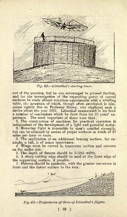
Fig. 42. Lilienthal's starting tower.
out of the question, but he was encouraged to proceed further,and for the investigation of the supporting power of curvedsurfaces he made almost countless experiments with a whirlingtable, the invention of which, though often attributed to him,seems rightly due to Professor Marey, who employed such adevice about the year 1870. Lilienthal enumerated in his booka number of conclusions which he drew from his 25 years' ex-
perience. The most important of these were that:1. The construction of machines for practical operation is
independent of the development of a light and powerful motor.2. Hovering flight is impossible by man's unaided strength,
but can be attained by means of proper surfaces in winds of 22miles per hour or more.
3. The application of an additional bearing surface, for ex-
ample, a tail, is of minor importance.4. Wings must be curved in transverse section and concave
on the under side.
5. The depth of flexure should be l-12th width.6. A sharp cutting edge should be used at the front edge of
the supporting surface, if possible.7. Flexure should be parabolic, with the greater curvature in
front and the flatter surface to the rear.
Fig. 43. Trajectories of three of Lilienthal's flights.
( 50 )
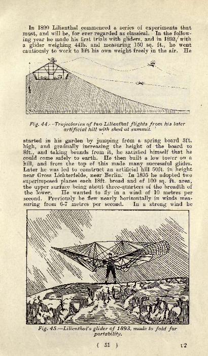
In 1890 Lilienthal commenced a series of experiments that
must, and will be, for ever regarded as classical. In the follow-
ing year he made his first trials with gliders, and in 1893/witha glider weighing 441b. and measuring 150 sq. ft., he went
cautiously to work to lift his own weight freely in the air. He
c**-...
ill(/^
Fig. 44. Trajectories of two Lilienthal flights from his later
artificial hill -with shed at summit.
started in his garden by jumping from a spring board 3ft.
high, and gradually increasing the height of the board to
8ft., and taking bounds from it, he satisfied himself that hecould come safely to earth. He then built a low tower on a
hill, and from the top of this made many successful glides.Later he was led to construct an artificial hill 50ft. in heightnear Gross Lichterfelde, near Berlin. In 1895 he adopted two
superimposed planes each 18ft. broad and of 100 sq. ft. area,the upper surface being about three-quarters of the breadth of
the lower. He wanted to fly in a wind of 10 metres persecond. Previously he flew nearly horizontally in winds mea-
suring from 6-7 metres per second. In a strong wind he
Fig. 45. Lilienthal's glider of 1893, made to fold forportability.

Fig. 46.Lilienthal's double-deck glider of 1895.
frequently allowed himself to be lifted from the top of thehill without the necessity for running down the slope, andoftentimes he found himself higher than the top of the hill.
To take longer glides, he went in 1896 to the Rhinerow Hills,where he had been in 1893 for a fair time. From the top of
some hills there 250ft. high he glided sometimes 750ft. or more.
Unfortunately, in the search for that soaring flightwhich seemed to fascinate him, he was caught inan awkward current, and the machine, losing its
equilibrium, carried him plumb to the ground,breaking his collar bone, from which injuryhe died within 24 hours. With him the
study of flight had always been
hobby. Glid-
ing with him ^~~~ "^became a C^__x"sport. Howmuch furtherhe wouldhave pro-
had
Fig. 47. The model arrived at by Lilienthal just before his death.
he been spared from that accident on August 12th, 1896, it is
impossible to . say, but from his work has proceeded all the
great and important success which has within the last few
years been attained in the art and science of human flight.From his pupils Herring, Pilcher and Ferber have grown the
schools of America, England and France, respectively.

IV. In America : Langley and Chanute.
The history of the American aeroplane resolves itself in the
popular mind to the doings of the two Wrights. However, it
must be borne in mind that, though these two clever inventors
accomplished the feat of flying before anyone else, they hada vast amount of work already done for them.
Langley with whom was*
associated Dr. Graham Bell
Chanute and Herring were first in the field; Langley and Bell,
who were working on their own lines, had been co-operating for
two years before Chanute came on the scene, for Langleystarted in 1893. Chanute began with the assistance of Herring,who had been a pupil of Lilientnal, and, while in no wise dis-
counting the Americans' achievements, we see in Lilienthal the
groundwork of Chanute's success. But Langley and his adviser
Bell, Chanute and his engineer Herring were all handicappedby the absence of light motive pow
rer such as that of the
petrol engine. They all stopped, because progress was impos-sible until the day of the light efficient engines.
Langley is recognised as being one of the first to make an
aeroplane that would actually fly. In making his report onthe subject, Langley modestly stated that,
" to prevent mis-
apprehension, let me state at the outset that I do not under-take to explain any art of mechanical flight, but to demonstrate
experimentally certain propositions in aerodynamics which provethat such flight under proper directions is possible."
Langley recognised that to try to imitate the action of abird was useless, and in his endeavour to master the problemof flight he employed an aeroplane, or, as he called it, aero-
drome. To assist him in his pioneer work he used the whirlingtable. With this he was able to prove that the figures prepared
Fig. 48. Langley 's mode devised in 1893 and firstflownin 1896.
( 53 )

by a well-known French mathematician were wrong, likewiseNewton's rule for finding the resistance to advance throughair. Otherwise, as he pointed* out, the swallow would have tobe nearly as strong as a man to enable it to travel at 60 miles
per hour. Since he first propounded his famous theory, wellknown as Langley's law, he has qualified the remarks to theextent that, though it still reads as it did at first, to the effect
that less power is spent in making a plane surface travel fast
through the air than would be spent in making it travel slowly,that statement applied only to the ideal condition of a friction-
less plane, and not to an actual flying machine.
Fig. 49. The Langley model in actual flight, May 6th, 1896.
Undoubtedly Langley would have furthered that art of flyingif he could have had the assistance of the petrol motor. Heexperimented with compressed air, carbonic acid gas, electri-
city and other means of obtaining power. Finally, he settled
upon steam, though he stated that he thought the gas enginewould be the motive power of the future. When using steamhe was terribly handicapped, for the engine, generator, etc.,
weighed 7^1b. per h.p., and his water supply would only last
long enough for a flight of 1^ minute.The innumerable difficulties that he had to overcome can be
gauged from the fact that it was not until May 1st, 1896, that
his machine actually flew, although it was three years previ-
ously that he first started his experimental work.As the illustration shows, Langley's aerodrome was shaped
like a butterfly, and consists of a main girder lying in thedirection of flight, to which the four plane surfaces are attached
fore and aft, the power unit and propellers being placed imme-
diately behind the front pair of wings. Langley claimed that
with this model he had proved flight to be possible.
Herring and Chanute were very closely allied in aeroplane
work, though together they never got beyond the experimental
( 54 )

Fig. 50. Chanute's experimental multiplane glider.
stage in gliders. Herring was a pupil of Lilienthal, but hesoon broke away from the lines of the German engineer. Hebrought to Chanute's notice the German inventor's discoveries,and appears to have really started the latter 's interest in gliding
experiments as a means towards the conquest of the air, so thatin 1895 he and Chanute constructed a glider like Lilienthal's,
though slightly modified. This glider was shaped like the out-
stretched wings of a bird, the top surface being concave and
Fig. 51. Chanute's final form without vertical planes.
( 55 )

the under convex. With this machine, which had a sustainingsurface of 168 sq. ft. and weighed 361h., he made a number of
experiments. His longest glide was 168ft. Chanute found thatthis type of glider was quite safe, and landed gently, hut it
would not travel any real distance unless the experimental hill
was steep as well as long. In other words, it dropped too muchin gliding. His next machine had eight separate planes, placedin pairs above one another. The point to notice with this
glider, which had the position of the planes definitely alteredseven times, irrespective of adjustment, is this : it
"
had the
planes curved from the front view, though flat from the side
aspect. This glider gave longer flights. Chanute then aban-doned this glider, and constructed a biplane with planes flat
Fig. 52. Chanute 's penultimate form, of double-deck glidingmachine the side planes were finally abandoned.
from the front aspect, but arched from the side. This was amost important step. The result was that he immediatelydoubled the length of his flights. With the biplane he had acertain amount of unsteadiness that he had not previously ex-
perienced, and which he does not account for. However, heovercame that by attaching a vertical rudder to his glider somedistance at the rear and on the same level as the load.
Chanute was of the opinion that not much was to be learned
from studying the action of flying creatures, because they varyBO in the amount of their supporting surface. He thinks thathis most valuable discovery was when he found that a plane
presenting a flat appearance from the front and arched fromthe side had the greatest lifting capacity.
( 56 >
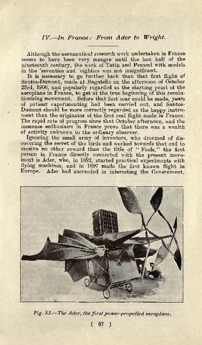
IV. In France: From Ader to Wright.
Although the aeronautical research work undertaken in Franceseems to have been very meagre until the last half of the
nineteenth century, the work of Tatin and Penaud with modelsin the 'seventies and 'eighties was not insignificant.
It is necessary to go further back than that first flight of
Santos-Dumont, made at Bagatelle on the afternoon of October
23rd, 1906, and popularly regarded as the starting point of the
aeroplane in France, to get at the true beginning of this revolu-
tionising movement. Before that first soar could be made, yearsof patient experimenting had been carried out, and Santos-Dumont should be more correctly regarded as the happy instru-ment than the originator of the first real flight made in France.The rapid rate of progress since that October afternoon, and theimmense enthusiasm in France prove that there was a wealthof activity unknown to the ordinary observer.
Ignoring the small army of inventors, who dreamed of dis-
covering the secret of the birds and worked towards that end toreceive no other reward than the title of
"Fools," the first
person in France directly connected with the present move-ment is Ader, who, in 1892, started practical experiments withflying machines, and in 1897 made the first known flight in
Europe. Ader had succeeded in interesting the Government,
Fig. 53. The Ader, the first power-propelled aeroplane.
( 57 )

Fig. 54. Experiments at Issy with a glider in 1900, powerbeing obtained by towing the glider with-a car.
and after a very short flight on October 12th, 1897, on the
Satory ground, in the presence of General Mesnier, a demon-stration was ordered to be made the following day before a
military commission. October 14th, which was later fixed as
the date of the trial, was a gusty autumnal day most un-favourable for aeronautical experiments, and although Ader wasable to rise from the ground, his machine was incapable of
struggling against the strong wind, and made such a poor dis-
play that the Government lost interest in the matter. Aderwas abandoned, and, discouraged after 40 years' labour and the
expenditure of two million francs, he commenced the destructionof his machines. One of them, however, was saved, and nowfigures in the Arts et Metiers Museum, at Paris, by the side of
the biplane with which Wright first flew in France.M. Tatin, one of the most distinguished of French explorers in
the realms of aeronautics, built a model flying machine in 1896for M. Richet. *The machine flew, but during one of the experi-ments near the sea it travelled for a distance of 150 yards, cap-sized and disappeared in fhe water. As the little experimenthad cost nearly one thousand pounds sterling, the supporter lost
all interest in flying with the disappearance of the machine.It was in 1899 that Captain Ferber began a long series of
experiments with gliders, endeavouring to take up the work thathad been carried on with so much success by the German Lilien-
thal, but he was unable to make the least gliding flight until
1901. Like Lilienthal, he attached himself to the apparatus bythe shoulders and arms, steering by carrying his legs ahead, tothe rear, or to left and right, but was not able to glide on the
layers of air as had been done by his German master. In 1901,he suddenly perceived that flights of this nature could only bemade with an ascending wind. It was not sufficient to run downa gentle slope, for the speed of 3ft. to 6ft. a second thus obtainedwould be altogether insufficient to support a man on such an un-
buoyant element as air. A horizontal head wind was altogether

unfavourable, for if it caught the wings on the upper surface the^
effect would be to hold the apparatus down to earth. On the'
other hand, if the apparatus were at such an angle that thewind struck the under surface, the apparatus would be raised,but would not be able to advance in the face of the wind, and,after a flutter in the air, would be driven backwards towardsthe ground. With the wind blowing up the slope, it was pos-sible for the aviator to run down, with the front of his apparatusinclined towards the ground, in what would appear to be in theface of the wind; the upward current of air, however, wouldhave a lifting effect which would allow the experimenter to glideahead, gradually descending all the time.
Captain Ferber, in France, kept in touch with the work beingdone in America by Chanute, Herring and Avery, as well as withthe earlier experiments of the Wright Brothers, with the result
Fig. 55. Experiments in gliding in 1900-1902 byM.. Ernest Archdeacon and Gabriel Voisin.
that progress was being made simultaneously on each side ofthe Atlantic. The " Ferber No. 5," of the Chanute and Wrighttype, after a few unsuccessful initial attempts, made satisfactorygliding flights at Beuil, in 1902. The experiments were con-tinued the following year at Conquet, in Finisterre, with equalsuccess, the apparatus, which had then a very strong resem-blance to the one being used on the other side" of the Atlantic
by Wilbur and Orville Wright, making numerous gliding flightswith perfect stability. It was considered so satisfactory that the
problem of driving it mechanically was taken into consideration.
Captain Ferber estimated that the weight of engine he could
put on the machine was 2201b. In 1903 all the power he couldobtain for this weight was 6h.p., delivered by a Buchet petrolmotor. A new biplane, known as " No. 6," was built on thesame lines as the preceding one, fitted with the Buchet engine
( 59 )
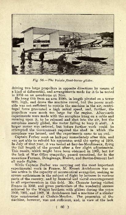
Fig. 56. The Voisin float-borne glider.
driving two large propellers in opposite directions by means of
a kind of differential, and arrangements made for it to be testedin 1903 on an aerodrome at Nice.He hung this from an arm 100ft. in length pivoted on a tower
60ft. high, and drove the machine round, but the power avail-
able was not sufficient to sustain the machine in the air, centri-
fugal force prevented a high initial speed, and, further, the
propellers were much too large for the engine. Afterwards
experiments were made with the aeroplane hung on a cable and
running upon it, to be released and shot into the air, but the
aeroplane merely glided, the motor failing to keep it aloft. Alarger motor was ordered, but before further work could be
attempted the Government required the shed in which the
aeroplane was housed, and the experiments came to an end.
Captain Ferber went on half-pay immediately after this, andwas not able to rebuild his apparatus until the spring of 1908.In July of that year, it was tested at Issy-les-Moulineaux, flyingthe full length of the ground after a few slight adjustments.This result, which might have been obtained in 1905, but forthe lack of War Office sympathy, passed unnoticed, for in themeantime Farman, Delagrange, Bleriot, and Santos-Dumont hadall made flights.While Captain Ferber was carrying out the most important
experimental work in France, M. Ernest Archdeacon was noless active in the capacity of aeronautical evangelist, seeking toarouse enthusiasm in the subject of flight by lectures in various
parts of the country, and by financial and moral encouragementto all experimenters in this field. Mr. Chanute having visited
France in 1903, and given particulars of the wonderful successachieved by the Wright brothers with gliders during the years1900, 1901, and 1902, M. Archdeacon had a machine of a similar
type constructed at Chalais-Meudon. The possession of the
machine, however, was not sufficient, and, in view of the lack
( 60 )

of experience in its handling, as well as the different conditions
under which it had to operate there, nothing practical was donein this line.
Gabriel Voisin was introduced to M. Archdeacon in January,1904, and less than three months later the two were makinggliding nights together at Berck-sur-Mer.
Gabriel Voisin, who mounted the apparatus, was at first un-
able to make a flight, and it was only after Captain Ferber hadbeen brought from Nice to explain that they must operate in
an ascending wind, that practical results were obtained. Berck-sur-Mer was not an ideal spot for gliding experiments, and in
order to be nearer their workshops, the party returned to Paris,
where, for want of a hill on which to make glides, the aeroplanewas towed by a motorcar across the military drill ground at
Issy-les-Moulineaux. The method of operation was to placethe aeroplane, without motor, but with a pilot on "board, onsuitable rails, attach it by means of a tow-rope to the motorcar,and pull it until it rose in the air in the same way as a kite.
It was not a very satisfactory arrangement, and after an acci-
dent on March 25th, 1905, when the machine flopped to the
ground and was completely destroyed, these experiments wereabandoned. Fortunately, on this day the pilot had been re-
placed by a sack of sand.
Believing there was less danger en the water, the aviators
abandoned Issy and took up their headquarters at the Surcoufestablishment at Billancourt, on the River Seine. The mostremarkable performance was made on June 8th, 1905, when the
aeroplane, mounted on two long floats, piloted by Gabriel Voisin,and towed by the motor-boat "
Rapiere," rose to a height of
55ft. and covered a distance in the air of not less than 160 yards.The apparatus had then very closely approached the form to be
adopted later by the aeroplane with which Farman was so
Fig. 57. Gabriel Voisin in his glider towed over the Seineby a fast motor-boat.
( 61 )

successful. It had two main superimposed planes, about 60in.
apart, united by four vertical planes to give lateral stability.In the rear was a tail, composed in the same manner, but of
much smaller dimensions than the main bearing surfaces. Inthe front was a single horizontal plane forming the functions
of elevation rudder.It was not long before experiments on water were proved to
be even more dangerous than those on land. Six weeks after
-the experiment just mentioned, Voisin again tested the Arch-
Fig. 58. Bleriot " 9bis"running over the ground in 1906.
deacon aeroplane on the Seine with but moderate results, anda few hours latar took out a new apparatus which he had built
for M. Louis Bleriot. While being towed by the motor-bpat"Antoinette," the aeroplane suddenly dived under the water,
taking Voisin with it. The aviator only succeeded in extractinghimself from under the planes at the end of 20 seconds, which
appeared to be 20 minutes to the anxious spectators. A little
later, M. Archdeacon removed to the Lake of Geneva, hopingthere to get a powerful motor boat which would tow him con-
stantly head on to the wind, a thing which was practically impos-sible on such a narrow river as the Seine. A suitable boat could notbe found, and the only practical result of the visit was a little
experiment made by Gabriel Voisin when -the aeroplane was
lying at anchor on the lake. In a very strong wind Voisin
discovered that he could cause the aeroplane to rise from thesurface of the water merely by operating the elevation rudder,and remain in the air, struggling at its cable until a lull in thewind or the manipulation of the rudder caused it to descend.The year 1906 opened with tremendous activity among French
< 62 )

Fig. 59. So.ntos-Dum.ont's famous aeroplane" 14bis "
comingup for -the \start of its first flight. The elevation planes -were
carried at the forward end of the body.
aeronauts, and a firm belief on the part of enthusiastic inventorsthat the day was very near when a mechanically-driven machinewould rise from the ground and maintain itself in the air, afeat which had never been accomplished in Europe, with the
exception of the brief and almost-forgotten soar of Ader in 1897.
The Wright brothers claimed to have made flights the previousyear varying from 25 to 38 minutes' duration, and, althoughtheir statements were far from being generally accepted in
France, the mere possibility of the Americans having made a
flight at all incited everyone to increased efforts on this side
of the Atlantic.
Gabriel Voisin had joined Louis Bleriot in business as aero-
plane constructors, and, together, the aeroplanes Nos. 3 and 4were built and experimented with on the lake at Enghien, near
Paris, and at Issy-les-Moulineaux.Santos-Dumont's first idea Avas to build a helicoptere ;
several
technical advisers persuaded him that this would be a waste of
time and energy, and, in consequence, an aeroplane of the Har-
greave box kite type was constructed and shown to the membersof the Aero Club in July, 1906. The first Santos-Dumont aero-
plane, known as the "14bis," was attached to No. 14 dirigible
balloon, the young Brazilian sportsman at that time not havingsufficient confidence in the heavier-than-air type of flyingmachine to attempt a flight from the ground in the generallyaccepted manner. It was immediately seen that the dirigibleballoon was more of a hindrance than a help, and other aids werelooked for. After various experiments with an inclined cable
and, later, with an inclined wooden track, the machine wassent away over the Bagatelle ground on its four wheels andunder the effort of its 24h.p. Antoinette motor.
( 63 )

Fig. 60. The starting-point of the aeroplane movementin France. The flight of Santos-Dumont's " 14bis "
at
Bagatelle, October 23rd, 1906.
There was an immediate improvement, and it was not manydays before the apparatus was running about in all directions.
The motor was changed for a larger one developing 50h.p., while,
longitudinal stability having proved to be perfect, the two rear
wheels were abandoned, leaving the front ones only. From Julyto October had been spent in experiments ;
but so rapid was the
progress that, on the 23rd of that month, Santos-Dumont called
together the Aviation Commission of the Aero Club of France,and at 4.45 in the afternoon won the Archdeacon prize for the
first flight of not less than 25 metres. Excitement was at sucha high pitch when this huge motor-driven box kite rose fromthe ground, that the Commission forgot to measure the distance
covered in the air. Although officially given as 25 metres, it
was generally recognised that the actual distance was not less
than 70 yards. The first flight ended with the breaking of thewheels of the aeroplane, for, the apparatus having set up a slow
lateral roll while in the air, Santos-Dumont switched off the
ignition and allowed his machine to descend abruptly, instead of
guiding it down gently.A month later, the flying record had been carried to 220
metres, and enthusiasm in French aero circles had reached its
height. Among the general public, however, the belief was
prevalent that the so-called flights were only jumps, comparableto the leaps that could be made by a man running at high'speed, or even by a motorcar when driven fast. Santos-Dumont'sfirst success was not rationally followed up, and, after variousunsuccessful attempts with small area high-speed flyers, the
young Brazilian abandoned the aeroplane to endeavour to con-
struct an apparatus to travel at 100 kilometres an hour on water.
( 64 )

Fig. 61. Henry Farman^wins the Archdeacon-Deutsch prizeof 2,000, by covering a triangular course of one kilometre,
on January 13th, 1908.
Gabriel Voisin. who, during 1906, had dissolved his partner-ship with Bleriot and been joined by his brother Charles, had
developed his own type of aeroplane while working out the ideasof his customers. He discovered, however, that inventors whowere willing to pay for aeroplanes wished to have them accordingto their own ideas. It was not until the Parisian sculptor Leon
Delagrange came forward in the early part of 1907 that he couldfind anybody to accept the machine produced as the result ofthe gliding flights at Berck-sur-Mer, and the experiments onthe Seine and elsewhere. The first Voisin machine, known asthe "
Delagrange No. 1," was tested at Vincennes on February28th, 1907, Charles Voisin mounting it. It was so lightlyconstructed that the backbone of the machine broke. A fort-
night later it was out again at Bagatelle, but failed for lack of
lateral balance. Finally, on March 30th, still on the Bagatelle-
ground, the machine went into the air for a magnificent flight of
60 yards.Instead of continuing his training after this very satisfactory
debut, Leon Delagrange abandoned the Voisin machine to carryout experiments with M. Archdeacon on the Lake of Enghien.In June, Henry Farman came forward with a request for a
machine, and the "Henry Farman No. 1," differing from the
"Delagrange No. 1
"in the method of attachment of the. wheels
only, was supplied to him.With true Anglo-Saxon thoroughness, for Henry Farman is
of British parentage, the new recruit set to work for a thoroughtraining. A shed was built on the edge of the Issy-les-Mouli-neaux ground the first of its kind and for a whole monthFarman scurried over the ground thoroughly familiarising
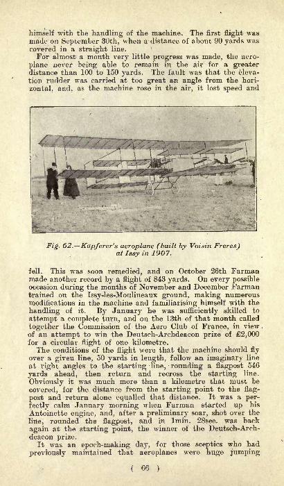
himself with the handling of the machine. The first flight wasmade on September 30th, when a distance of about 90 yards wascovered in a straight line.
For almost a month very little progress was made, the aero-
plane never being able to remain in the air for a greaterdistance than 100 to 150 yards. The fault was that the eleva-
tion rudder was carried at too great an angle from the hori-
zontal, and, as the machine rose in the air, it lost speed and
; ,
,
(
,<^-. ^ \
\ * L <*T^*rm*m&~'~' ^^^^K 'i
n *f9ff^SffT ~ mmFig. 62. Kapferer's aeroplane (built by Voisin Freres)
at Issy in 1907.
fell. This was soon remedied, and on October 26th Farmanmade another record by a flight of 843 yards. On every possibleoccasion during the months of November and December Farmantrained on the Issy-les-Moulineaux ground, making numerousmodifications in the machine and familiarising himself with the
handling of it. By January he was sufficiently skilled to
attempt a complete turn, and on the 13th of that month called
together the Commission of the Aero Club of France, in viewof an attempt to win the Deutsch-Archdeacon prize of 2,000for a circular flight of one kilometre.
The conditions of the flight were that the machine should fly
over a given line, 50 yards in length, follow an imaginary line
at right angles to the starting line, rounding a flagpost 546
yards ahead, then return and recross the starting line.
Obviously it was much more than a kilometre that must be
covered, for the distance from the starting point to the flag-
post and return alone equalled that distance. It was a per-
fectly calm January morning when Farman started up his
Antoinette engine, and, after a preliminary soar, shot over the
line, rounded the flagpost, and in Imin. 28sec. was back
again at the starting point, the winner of the Deutsch-Arch-deacon prize.
It was an epoch-making day, for those sceptics who had
previously maintained that aeroplanes were huge jumping
( 66 )
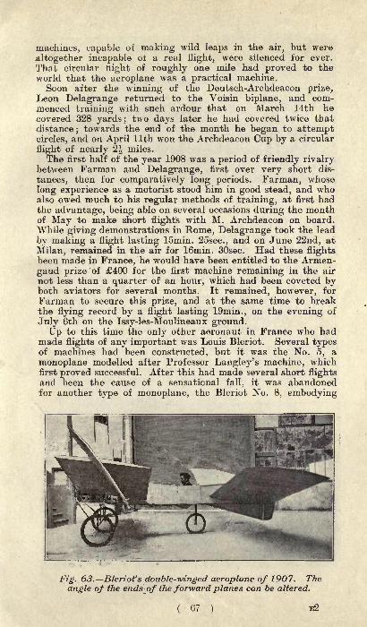
machines, capable of making wild leaps in the air, but were
.altogether incapable of a real flight, were silenced for ever.
That circular night of roughly one mile had proved to theworld that the aeroplane was a practical machine.Soon after the winning of the Deutsch-Archdeacon prize,
Leon Delagrange returned to the Voisin biplane, and com-menced training with such ardour that on March 14th hecovered 328 yards ;
two days later he had covered twice thatdistance
;towards the end of the month he began to attempt
circles, and on April llth won the Archdeacon Cup by a circular
flight of nearly 2^ miles.
The first half of the year 1908 was a period of friendly rivalrybetween Farman and Delagrange, first over very short dis-
tances, then for comparatively long periods. Farman, whose
long experience as a motorist stood him in good stead, and whoalso owed much to his regular methods of training, at first hadthe advantage, being able on several occasions during the monthof May to make short flights with M. Archdeacon on board.
While giving demonstrations in Rome, Delagrange took the lead
by making a flight lasting lomin. 25sec., and on June 22nd, at
Milan, remained in the air for 16min. 30sec. Had these flightsbeen made in France, he would have been entitled to the Armen-
gaud prize of 400 for the first machine remaining in the air
not less than a quarter of an hour, which had been coveted byboth aviators for several months. It remained, however, for
Farman to secure this prize, and at the same time to breakthe flying record by a flight lasting 19min., on the evening of
July 6th on the Issy-les-Moulineaux ground.Up to this time the only other aeronaut in France who had
made flights of any important was Louis Bleriot. Several typesof machines had been constructed, but it was the No. 5, a
monoplane modelled after Professor Langley's machine, whichfirst proved successful. After this had made several short flightsand been the cause of a sensational fall, it was abandonedfor another type of monoplane, the Bleriot No. 8, embodying
Fig. 63. Bleriot's double-winged aeroplane of 1907 . The
angle of the ends of the forward planes can be altered.
( 67 ) E2

Fig. 64. Capt. Ferber's later experiments at Issy in July, 1908.
many of the ideas of M. Tatin, which proved to be the mostsuccessful monoplane then known in France. The morning thatFarman won the Armengaud prize Bleriot made a flight of8min. 24sec., his progress only being stopped by the failure of
the pressure in the petrol tank.
Activity, however, was not confined to these three. But thescore or so who were endeavouring to fly had not been able torealise anything more important than trips lasting a few seconds.In 1906 Vuia had left the ground on a monoplane for a distanceof five or six yards, lengthened a year later to a flight of 60
yards ;Robert Esnault-Pelterie flew as early as October, 1907
;
Comte de la Vaulx flew 60 yards in November of the same year ;
De Pischoff flew a kilometre on a biplane in December, 1907, and
Gastambide-Mengin made his first flights with an Antoinette
monoplane in February, 1908. Paul Cornu's helicoptere man-aged to rise from the ground to a height of about 16in. on
Fig. 65. Bleriot No. II. at Issy.
( 68 )
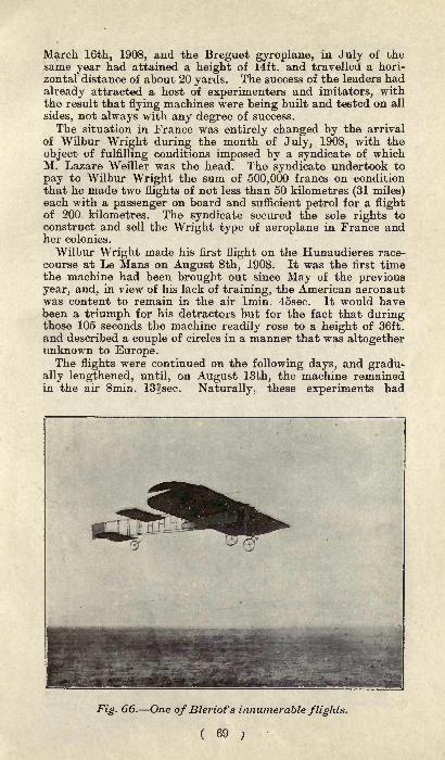
March 16th, 1908, and the Breguet gyroplane, in July of thesame year had attained a height of 14ft. and travelled a hori-
zontal distance of about 20 yards. The success of the leaders had
already attracted a host of experimenters and imitators, withthe result that flying machines were being built and tested on all
sides, not always with any degree of success.
The situation in France was entirely changed by the arrival
of Wilbur Wright during the month of July, 1908, with the
object of fulfilling conditions imposed by a syndicate of whichM. Lazare Weiller was the head. The syndicate undertook to
pay to Wilbur Wright the sum of 500,000 francs on conditionthat he made two flights of not less than 50 kilometres (31 miles)each with a passenger on board and sufficient petrol for a flightof 200 kilometres. The syndicate secured the sole rights toconstruct and sell the Wright type of aeroplane in France andher colonies.
Wilbur Wright made his first flight on the Hunaudieres race-
course at Le Mans on August 8th, 1908. It was the first timethe machine had been brought out since May of the previousyear, and, in view of his lack of training, the American aeronautwas content to remain in the air Imin. 45sec. It would havebeen a triumph for his detractors but for the fact that duringthose 105 seconds the machine readily rose to a height of 36ft.
and described a couple of circles in a manner that was altogetherunknown to Europe.The flights were continued on the following days, and gradu-
ally lengthened, until, on August 13th, the machine remainedin the air 8min. 13|sec. Naturally, these experiments had
Fig. 66. One of Bleriot's innumerable flights.

attracted enormous crowds of spectators, much to the annoyanceof Wright, who had innocently imagined that, after the first
two or three flights, he would be left to work alone. A removalwas therefore made to the Camp d' Auvours, a vast pine-borderedplain about seven miles out of town, difficult of access andunused except for military manreuvres.Almost immediately after the arrival at the Camp d' Auvours,
the flights were lengthened, Wilbur Wright remaining in the air
19min. 48fsec. on September 5th, almost equalling the distancecovered by Delagrange and Farman in the previous month.But there were still more important flights in store, and, aftera soar of 2min. 20sec. with M. Ernest Zens as passenger, on
Fig. 67. "La Demoiselle," Santos-Dtimont's miniature flying, mo.ch.ine at St. Cyr in the autumn of 1908.
September 16th, Wilbur Wright sent in his entry for the
Michelin Cup and the Prix de la Commission d'Aviation of theA.C.F.
In the afternoon of Septeihber 21st, after three false starts,
due to the rail being badly placed, Wilbur Wright remained in
the air for Ihr. Slmin. 25fsec., thus creating a world's record
for both time and distance, and provisionally securing theMichelin Cup and the Commission d'Aviation's prize. As he
stepped from the machine amid the tremendous excitement of
the mass of spectators gathered on the ground, he remarked:" That will cheer up Orville a bit." The conditions of the two
prizes were that the flight should take place before sunset;thus
( 70 )
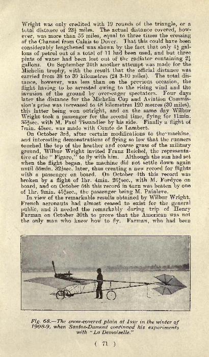
Wright was only credited with 19 rounds of the triangle, or a
total distance of 23^ miles. The actual distance covered, how-
ever, was more than 55 miles, equal to three times the crossingof the Channel from Calais to Dover. That this could have been
considerably lengthened was shown by the fact that only 4f gal-lons of petrol out of a total of 11 had been used, and but three
pints of water had been lost out of the radiator containing 2
gallons. On September 24th another attempt was made for the
Michelin trophy, with the result that the official distance wascarried from 38 to 39 kilometres (24 3-10 miles). The total dis-
tance, however, was less than on the previous occasion, the
flight having to be arrested owing to the rising wind and the
invasion of the ground by over-eager spectators. Four dayslater the distance for the Michelin Cup and Aviation Commis-sion's prize was increased to 48 kilometres 120 metres (30 miles),this latter being won outright, and on the same day Wilbur
AVright took a passenger for the second time, flying for llmin.
3o|sec. with M. Paul Tissandier by his side. Finally a flight of
7min. 45sec. was made with Comte de Lambert.On October 3rd, after certain modifications to the* machine,
and interesting demonstrations of flying so low that the runners
touched the top of the heather and coarse grass of the military
ground, Wilbur Wright invited Franz Reichel, the representa-tive of the "
Figaro," to fly with him. Although the sun had set
when the flight began, the machine did not settle down againuntil 55min. 321sec. later, thus creating a new record for flightswith a passenger on board. On October 4th this record wasbroken by a flight of Ihr. 4min. 26fsec., with M. Fordyce on
board, and on October 5th this record in turn was beaten by oneof Ihr. 9min. 45fsec., the passenger being M. Painleve.
In view of the remarkable results obtained by Wilbur Wright,French aeronauts had almost ceased to exist for the general
public, and it needed the remarkably daring trip of HenryFarman on October 30th to prove that the American was not
the only man who knew how to fly. Farman, who had been
Fig. 68. The snow-covered plain at Issy in the winter of1908-9, when Santos-Dumont continued his experiments
with "La Demoiselle."
( 71 )

Fig. 69. The R.E.P. aeroplane" 2bis." Mr. Esnault-Pelterie i
is an advocate of the monoplane. -._ j
training for some time on the vast plain near Chalons, starteda little before four o'clock on a cross-country flight, his destina-
tion being Rheims, about 17 miles away. The machine, the onewhich had won the Deutsch-Archdeacon prize in January, was
immediately carried up to a height of over 130ft., in order to be
absolutely certain of clearing the tall poplar trees, telegraphwires, and other obstacles. In a few minutes the aeroplanewas lost to sight, and was not long in getting clear away fromthe motorcars which attempted to follow it. Exactly 20 minutesfrom the time he started, Henry Farman descended on the mili-
tary ground just outside the city of Rheims, having made thefirst cross-country flight at a speed of 45 miles an hour, and at
an average height of 130ft. It had been intended to return in
the same manner, but, owing to certain adjustments beingnecessary, this idea had to be abandoned. The following dayFarman competed for the height prize of the Aero Club of
France, and succeeded in passing over a couple of balloons placed80ft. above the ground.Louis Bleriot, who alone had been devoting attention to the
monoplane type of flyer, was not to be outdone by the Farmanexploit, and, on October 31st, set out on a round trip from Touryto Artenay and return, a distance of about 19 miles. Themachine used was the " Bleriot VIII.," equipped with a 50h.p.
eight-cylinder Antoinette engine. In llmin. the machine passedover Artenay, but a few seconds later had to descend owing to
irregularities in the working of the magneto. After Ihr. 30min.
spent in making adjustments, the monoplane went into the air
again, homeward bound. After covering about three miles asecond descent had to be made; this time, however, the stopwas only of a few minutes' duration, and, on going up again,the machine flew remarkably well until it reached its starting-
point, where a descent was made. The first round trip across
( 72 )

country had begun at 10.5 a.m. and ended at 5 p.m. A few
days later, while making trials near Toury, the Bleriot mono-
plane was smashed through striking a hillock when running over
the ground at high speed. The pilot, who had had more tumbles
than any other aeronaut in France, fortunately escaped with
his usual good luck.
The last flying competition in 1908 was for the Michelin Cup,to be awarded to the aviator making the longest flight duringthe year. Since his cross-country flight, Henry Farman had
considerably modified his machine, with a view to beating
Wright's record for the Michelin prize. Several different makesof motors were tried, whilst the structure of the aeroplane wasalso changed, the most important modification being the addi-
tion of another plane making the machine a triplane. It was
impossible, however, to make the aeroplane as satisfactory as
the Wright apparatus, and, although Henry Farman made someclever flights towards the end of the year, he never seriouslythreatened Wilbur Wright's supremacy. Early in JanuaryFarman sold his aeroplane to an Austrian syndicate, and, havingbroken with the Voisin Freres, commenced business as an aero-
plane constructor on his own account.
Although Wilbur Wright practically had the field to himself,he did not in the least relax his effort to make a record flight.On December 18th he covered an official distance round a tri-
angular course of 99 kilometres (61^ miles), his time in the air
being Ihr. 53min. 59fsec. The actual distance covered was notless than 75 miles, and his actual time Ihr. 54min. fsec. Onthe same day Wilbur Wright competed for the height prize of
the Aero Club of France, the minimum for which was 328ft.
Although a strong wind was blowing, this was won with ease,ihe small balloons being passed with a good margin, the actual
lieight being given as 377ft. Even this did not satisfy theAmerican aeronaut, and he declared he would try again the next
day, but was prevented by rain.
As if afraid that the Michelin trophy would escape from himat the last moment, Wilbur Wright made another attempt tobeat his own record on the last day of the year, and admirablysucceeded. Well wrapped up to withstand the biting breezefor the thermometer was at freezing point the aeroplane left
its rail just after two o'clock, and did not settle down againuntil sunset, having remained in the air 2hr. 20min. 23isec.
His official distance for the Michelin Cup was 123 kilometres200 metres (76^ miles), while the actual distance covered wasestimated at 93 miles.
( 73 )
'
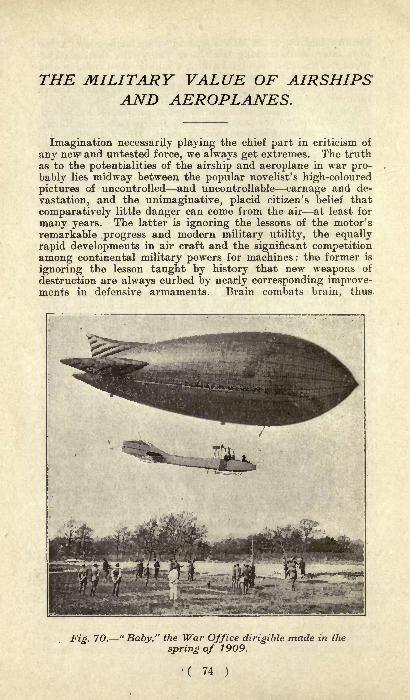
THE MILITARY VALUE OF AIRSHIPSAND AEROPLANES.
Imagination necessarily playing the chief part in criticism of
any new and untested force, we always get extremes. The truthas to the potentialities of the airship and aeroplane in war pro-
bably lies midway between the popular novelist's high-coloured
pictures of uncontrolled and uncontrollable carnage and de-
vastation, and the unimaginative, placid citizen's belief that
comparatively little danger can come from the air at least for
many years. The latter is ignoring the lessons of the motor's
remarkable progress and modern military utility, the equally
rapid developments in air craft and the significant competition
among continental military powers for machines : the former is
ignoring the lesson taught by history that new weapons of
destruction are always curbed by nearly corresponding improve-ments in defensive armaments. Brain combats brain, thus
Fig. 70. "Baby," the War Office dirigible made in the
spring of 1909.
( 74 )
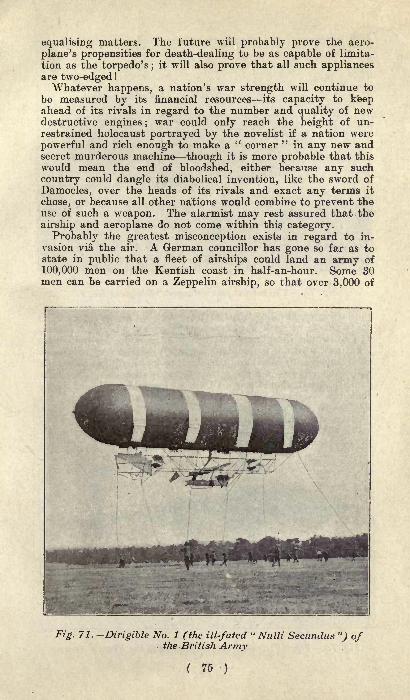
equalising matters. The future will probably prove the aero-
plane's propensities for death-dealing to be as capable of limita-
tion as the torpedo's ;it will also prove that all such appliances
are two-edged !
Whatever happens, a nation's war strength will continue to
be measured by its financial resources its capacity to keepahead of its rivals in regard to the number and quality of newdestructive engines; war could only reach the height of un-restrained holocaust portrayed by the novelist if a nation were
powerful and rich enough to make a " corner "in any new and
secret murderous machine though it is more probable that this
would mean the end of bloodshed, either because any such
country could dangle its diabolical invention, like the sword of
Damocles, over the heads of its rivals and exact any terms it
chose, or because all other nations would combine to prevent theuse of such a weapon. The alarmist may rest assured that the
airship and aeroplane do not come within this category.
Probably the greatest misconception exists in regard to in-
vasion via the air. A German councillor has gone so far as tostate in public that a fleet of airships could land an army of
100,000 men on the Kentish coast in half-an-hour. Some 30men can be carried on a Zeppelin airship, so that over 3,000 of
Fig. 71. -Dirigible No. 1 (the ill-fated" Nulli Secundus ") of
the British Army
( 75 )

Fig. 72. The rebuilt and enlarged "Dirigible No. 1."
the latter would be required to transport the above force. Theconstruction of such a number could scarcely be kept secret,and we would thus have time in which to make adequate pre-parations, whilst it is doubtful whether even Germany possessesthe resources, financial and chemical, to build, equip and supplywith sufficient gas in a short time so many machines. The last-
named, indeed, should prove an almost insoluble problem, seeingthat one airship of the above type requires anything from350,000 to 400,000 cubic feet of gas. But a more importantpoint is that only an airship of such size as to be almost un-
manageable in bad weather could take heavy supplies and muni-
tions, or guns of any size;and without ample cavalry or artillery
Fig. 73. The " Ville de Paris "attached to the French Army.
( 76 )
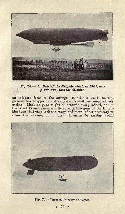
Fig. 74. "La Patrie," the dirigible which, in 1907, was*blown away into the Atlantic.
an infantry force of the strength mentioned would be dan-
gerously handicapped in a strange country if not comparativelyuseless. Machine guns might be brought over; indeed, one of
the latest French airships is fitted with two guns of the Hotch-kiss type ;
but they lack the range and" moral effect necessary tocover the advance of infantry. Invasion by airship would
Fig. 75. The new Parseval dirigible.
( 77 )

in short, prove to be so stupendous an undertaking, andattended by so many risks, contingencies, and almost prohibi-tive cost that one can agree with the Hon. C. S. Rolls that it"
is quite out of the question."The main drawback to the airship from the military point of
view is that it cannot be implicitly relied upon in all weathersand under all circumstances. This terrible uncertainty would,to some extent, put all commanders on a level
; military geniusbecomes a mockery when one is at the mercy of one's instru-
ments. There could be no dependence on an airship turning upat a definite spot within a given time
;a commander whose main
strength lay in airships might be suddenly crippled in violent
weather and compelled to capitulate to a force strong only in
the field. Military commanders might shun such machines, pre-
ferring to put their trust in the unmatchable resource, adapt-ability and intelligence of human beings. Air craft will be in-
dispensable adjuncts to an Army, but of secondary importanceonly. The construction of gun carriages that will admit of fire
almost up to the zenith is only a question of time, and, properly
equipped in this respect, our forts and naval bases would beable to bring such a sustained bombardment to bear on anyhovering airships as to make the latter' s position absolutely un-
tenable. The failure of recent experiments of this kind at
Gibraltar need cause no uneasiness; for much better results
Fig. 76. The Baldwin dirigible attached to the AmericanWar Department.
( 78 )
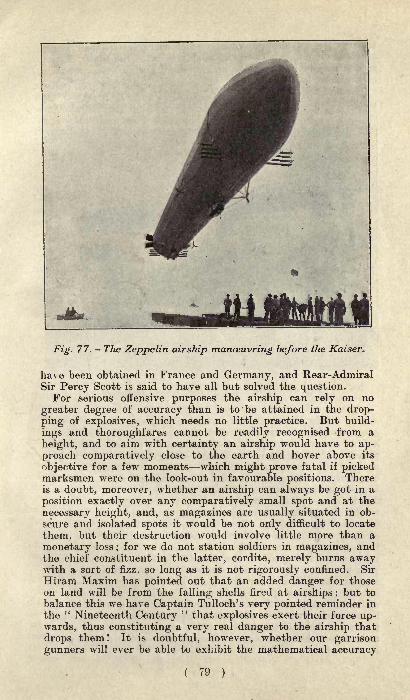
Fig. 77. - The Zeppelin airship manoeuvring before the Kaiser.
have been obtained in France and Germany, and Rear-AdmiralSir Percy Scott is said to have all but solved the question.
For serious offensive purposes the airship can rely on no
greater degree of accuracy than is to be attained in the drop-ping of explosives, which needs no little practice. But build-
ings and thoroughfares cannot be readily recognised from a
height, and to aim with certainty an airship would have to ap-
proach comparatively close to the earth and hover above its
objective for a few moments which might prove fatal if pickedmarksmen were on the look-out in favourable positions. Thereis a doubt, moreover, whether an airship can always be got in a
position exactly over any comparatively small spot and at the
necessary height, and, as magazines are usually situated in ob-
scure and isolated spots it would be not only difficult to locate
them, but their destruction would involve little more than a
monetary loss;for we do not station soldiers in magazines, and
the chief constituent in the latter, cordite, merely burns awaywith a sort of fizz, so long as it is not rigorously confined. Sir
Hiram Maxim has pointed out that an added danger for thoseon land will be from the falling shells fired at airships ;
but to
balance this we have Captain Tulloch's very pointed reminder in
the " Nineteenth Century" that explosives exert their force up-
wards, thus constituting a very real danger to the airship that
drops them ! It is doubtful, however, whether our garrisongunners will ever be able to exhibit the mathematical accuracy
( 79 )

towards the travelling aeroplane which characterises their firingat rapidly-moving battleships, simply because the flight of theformer may be both vertical and horizontal in direction, makingof it a most baffling target.The possibilities of the airship on night manoeuvres have been
It could place no check on an enemy's move-
Fig. 78. The Zeppelin over Lake Constance.
ments, seeing that only the darkest nights are chosen for sur-
prise attacks. Under such circumstances it would neither beable to observe and report the operations nor to make a counter-
attack. If all lights on land were extinguished it would have
nothing but a compass to rely on. On the other hand, it wouldbe clearly visible against the sky on a moonlight night, and thusa positive source of danger to its main force. The one great
disadvantage of the airship in actual campaigning is that it
would disclose the whereabouts of an opposing force, and the
direction it was taking. Even on the blackest nights, powerfulelectric searchlights could sweep the sky and disclose the posi-tion of any hovering airships. When certain developments havetaken place in regard to the former, another check will havebeen placed on the destructiveness of airships. The latter will
supplement railways for the more direct conveyance of dis-
patches, members of the staff, special supplies, and so on, butwill never supplant them. For airships will be unavailable for
heavy goods, and they will be too dependent on weather condi-
tions, and for this reason they can never equal the railways or
motor when the rapid concentration of troops at any given pointis desired.

No one will dispute for a moment the airship's utility for re-
connaissance work, observing the effects of artillery fire,
photographing positions, making rough maps of the country,and so on; but the military captive balloon has answered all
these purposes for over a hundred years, and the airship has the
same limitations, namely, fairly calm weather is essential for
making careful observations, and in a very mountainous countrythe range of outlook is restricted, for if the reverse slopes of
hills be steep they can effectually conceal an enemy's position.The difficulty of communication has also yet to be satisfactorily
solved, for, unless airships can be relied on to keep in direct
touch with headquarters, and, perhaps more important, withone another, the commander must leave them entirely out of
his calculations as being irresponsible and useless. Wireless
telegraphy will in due time doubtless step in here with completesuccess, though it is claimed that the aeroplane is not so well
adapted for the installation as the airship, and that even in thelatter case there is some risk of fire. The latter' s superiorityover the aeroplane in yet another military requisite is worthy of
note, for it can in certain circumstances rise direct from an en-closed space, descend at any desired spot, and manoeuvre more
easily.The airship and aeroplane bid fair to revolutionise gunnery,
musketry, and even the uses of cavalry, in the future. Therecan be no forecasting the composition of the army of the future
supposing such things are still in existence. Nor, apparently,would the present-day rules of strategy answer. For com-manders will have to take the weather into consideration, as
being an additional weapon to use against airships, to an extenthitherto undreamed of. Campaigning may consist of protractedmanoeuvring, mere dilly-dallying so as to ensure that battles are
fought on days when the climatic conditions place the enemy'sairships at a grave disadvantage. A snowstorm, which will
practically kill an airship, will be one of the few occasions whencontending armies will have an equal chance.The real war value of airships lies, as Captain Tulloch has
graphically portrayed, in their unlimited capacity for in-
cendiarism. With everything carefully mapped out beforehand,
they could operate over dense commercial districts and harbours^where untold stores of combustibles, such as oil, timber, and gasicould be found. These are also, in regard to population, the'
most congested centres;and it needs little imagination to pic-
ture the black ruin, desolation, and mad, reckless, fatal panicthat might be brought about in a few short hours by a group of
airships in skilful, determined hands. Mr. H. G. Wells hasdriven this truth home with ghastly realism in his vivid de-
scription of the destruction of New York in" The War in the
Air." " As the airships sailed along they smashed up the
city as a child will shatter its cities of brick and card. Below,they left ruins and blazing conflagrations and heaped and scat-
tered dead." In the same book he anticipates, too, the recentremark made by Lord Montagu of Beaulieu at the MansionHouse, to the effect that " the little island in the silver seas
"
is near the end of its immunity, its insularity. To make that
( 81 ) F

good by the establishment of a two-power standard in airships is
the only solution of the problem for politicians. There is onlyone way in which a great city can hope to escape wholesale de-
struction under the above circumstances, namely, by levellingall its fortifications and withdrawing its troops ;
for accordingto the Law of Nations no unfortified and undefended townshould be bombarded
;but history proves that rather than
suffer such a blow to their patriotism and pride the inhabitants
of a beleaguered town will endure anything.In conclusion, it may be said that airships will probably prove
of greater assistance in naval than in military warfare. For it
is common knowledge that when one is over the sea at somealtitude with the water smooth it is usually possible to see to
the bottom, and thus the presence of mines and submarinescould be detected and reported. Airships could serve as eyesand signal-stations to a fleet, as guides in long-range bombard-
ments, and as pilots in low-lying fogs.
i ^ A figure carved on the tomb of Rameses III. in the Louvre.:;, . Museum, Paris.
( 82 )
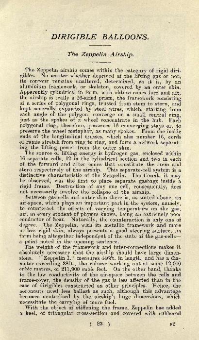
DIRIGIBLE BALLOONS.
The Zeppelin Airship.
The Zeppelin airship comes within the category of rigid diri-
gibles. No matter whether deprived of the lifting gas or not,its contour remains unaltered, determined, as it is, by analuminium framework, or skeleton, covered by an outer skin.
Apparently cylindrical in form, with obtuse cones fore and aft,the airship is really a 16-sided prism, the framework consistingof a series of polygonal rings, trussed from stem to stern, andkept severally expanded by steel wires, which, starting fromeach angle of the polygon, converge on a small central ring,just as the spokes of a wheel concentrate in the hub. Eachpolygonal ring, therefore, possesses 16 converging stays or, to
preserve the wheel metaphor, as many spokes. From the insideends of the longitudinal trusses, which also number 16, cordsof ramie stretch from ring to ring, and form a network separat-ing the lifting power from the outer skin.
The source of lifting energy is hydrogen gas, enclosed within16 separate cells, 12 in the cylindrical section and two in eachof the forward and after cones that constitute the stem andstern respectively of the airship. This separate-cell system is adistinctive characteristic of the Zeppelin. The Count, it maybe observed, was the first to place separate gasbags inside a
rigid frame. Destruction of any one cell, consequently, doesnot necessarily involve the collapse of the airship.Between gas-cells and outer skin there is, as stated above, an
air-space, which plays an important part in the system, namely,to counteract the effects of varying temperature on the gas,air, as every student of physics knows, being an extremely poorconductor of heat. Naturally, the counteraction is only one of
degree. The Zeppelin, with its metallic framework and moreor less rigid skin, always presents a good steering surface, its
form being altogether independent of the state of the gas-cellsa point noted in the opening sentence.The weight of the framework and inter-connections makes it
absolutely necessary that the airship should have large dimen-sions.
"Zeppelin I." measures 446ft. in length, and has a dia-
meter exceeding 38ft., the volume working out at some 12,000cubic metres, or 211,900 cubic feet. On the other hand, thanksto the low conductivity of the air-space between the cells andframe-cover, the density of the gas is less affected than in thecase of dirigibles constructed on other principles. Hence, theaeronauts need less ballast as such, although this advantagebecomes neutralised by the airship's huge dimensions, whichnecessitate the carrying of more fuel.
With the object of stiffening the frame, Zeppelin has addeda keel, of triangular cross-section and covered with rubbered
( 83 ) F2

Kk
tig8
A<;
15
tNQi
g|
ON
cioth to reduce resistance. Abouta fourth of the whole length fromeach end the keel is interruptedto admit of attachments for two
boat-shaped cars of aluminiumand steel tubing, connected by a
gangway containing, amongstother things, a wagon, which runson rails and can be hauled to andfro by wire cable, for preservingequilibrium. The cars have pneu-matic shock - absorbers under-neath. Each car is over 26ft. in
length, and hangs within 7ft. of
the outer skin, a proximity tend-
ing to obviate oscillation."Zeppelin I." has two sets of
horizontal-steering planes, fixed
high up, towards the middle of
the stern cone, at the rear end of
two laterally- placed steadying
planes, and operated from the
cars through an ingenious ar-
rangement of gear, wire andwheel. Each set consists of three
parallel planes of about 43 sq. ft.,
hanging, like ship's rudders, al-
most perpendicularly to the large
steadying planes, each over300 sq. ft. in area. The frames of
steering sets and other planes are
composed of aluminium rods, overwhich canvas is stretched, wires
holding the surfaces in position.
Change of altitude is effected bymeans of two pairs of plane-sets,the one forward and the other
astern, each set being made up of
four parallel planes, attached
laterally, just over the keel, to
the first ring of the cylindricalsection. Of course, their planesof position are identical with that
of the airship's axis, or at a tan-
gent with the body. As each of
the parallel planes terminates out-
wardly in a line with the others
of the same set, they differ in
length, being shorter according as
they approach the centre of theballoon's transverse curvature.The pairs can be worked alone or
together. They have severally anarea of about 240ft, Turned
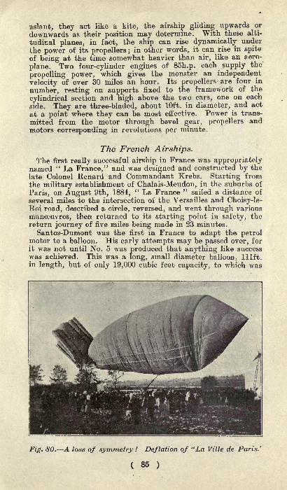
aslant, they act like a kite, the airship gliding upwards or
downwards as their position may determine. With these alti-
tudinal planes, in fact, the ship can rise dynamically under
the power of its propellers ;in other words, it can rise in spite
of being at the time somewhat heavier than air, like an aero-
plane. Two four-cylinder engines of 85h.p. each supply the
propelling power, which gives the monster an independent
velocity of over 30 miles an hour. Its propellers are four in
number, resting on supports fixed to the framework of the
cylindrical section and high above the two cars, one on each
side. They are three-bladed, about 10ft. in diameter, and act
at a point where they can be most effective. Power is trans-
mitted from the motor through bevel gear, propellers andmotors corresponding in revolutions per minute.
The French Airships.
The first really successful airship in France was appropriatelynamed " La France," and was designed and constructed by the
late Colonel Renard and Commandant Krebs. Starting fromthe military establishment of Chalais-Meudon, in the suburbs of
Paris, on August 9th, 1884," La France "
sailed a distance of
several miles to the intersection of the Versailles and Choisy-le-Roi road, described a circle, reversed, and went through various
manoeuvres, then returned to its starting point in safety, thereturn journey of five miles being made in 23 minutes.
Santos-Dumont was the first in France to adapt the petrolmotor to a balloon. His early attempts may be passed over, for
it was not until No. 5 was produced that anything like successwas achieved. This was a long, small diameter balloon, lllft.in length, but of only 19,000 cubic feet capacity, to which was
Fig. 80. A loss of symmetry ! Deflation of "La Ville de Paris.'
( 85 )

Fig. 81. "Clement-Bayard," a very successful ship.
attached a rough sort of platform receiving a four-cylinder
16h.p. petrol motor driving a large propeller. The accommoda-tion for the pilot was very mean, there being no car properly
speaking, but merely a bicycle saddle, with two pedals as on a
motorcycle, allowing the engine to be started up. It was adelicate construction, and needed the audacity of a Santos-Dumont to mount it.
The first important experiment was made on July 12th, 1901,when the airship went up from St. Cloud, crossed over the Seine,and came down on Longchamps racecourse less than a mile
away. On October 19th of the same year Dumont successfullyrounded the Eiffel Tower on his No. 6, returning in safety to
his starting point at St. Cloud, the winner of the Deutsch de la
Meurthe prize of 100,000 francs.
There was a temporary set-back to the airship movement bythe fatal accidents the following year to
"Pax," piloted by the
Brazilian Severe, and to the Bradsky airship." Pax " was
badly designed in respect to the position of its motors, theexhaust valve of the envelope being so near to one of the motorsthat a mass of gas formed outside the balloon and was fired.
Baron Bradsky, who used a non-rigid type of airship, met his
death, together with his companion, by the car breaking awayfrom the balloon when sailing over the suburbs of Paris.
Black as was the year 1902, it was nevertheless the starting
point of the practical airship movement in France, for at the
end of that year the Lebaudy dirigible was produced, and mademore than 50 journeys between October, 1902, and November,1.903, when it was wrecked by colliding with a tree during land-
ing operations in a heavy wind. This was followed by "LebaudyI.," even more successful than the first one, and which served
as a model for future military airships, among others the famous
( 86 )
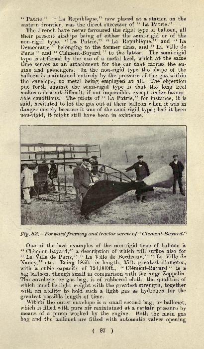
" Patrie."" La Republique," now placed at a station on the
eastern frontier, was the direct successor of" La Patrie."
The French have never favoured the rigid type of balloon, all
their present airships being of either the semi-rigid or of the
non-rigid type," La Patrie,"
" La Republique/' and " LaDemocratic "
belonging to the former class, and " La Ville de
Paris" and "
Clement-Bayard"
to the latter. The semi-rigid
type is stiffened by the use of a metal keel, which at the sametime serves as an attachment for the car that carries the en-
gine and passengers. In the non-rigid type the shape of the
balloon is maintained entirely by the pressure of the gas withinthe envelope, no metal being employed at all. The objectionput forth against the semi-rigid type is that the long keel
makes a descent difficult, if not impossible, except under favour-able conditions. The pilots of
" La Patrie," for instance, it is
said, hesitated to let the gas out of their balloon when it was in
danger merely because it was of the semi-rigid type ;had it been
non-rigid, it might still have been in existence.
Fig. 82. Forwardframing and tractor screw of" Clement-Bayard."
One of the best examples of the non-rigid type of balloon is"Clement-Bayard," a description of which will suffice also for
" La Vflle de Paris,"" La Ville de Bordeaux,"
" La Ville de
Nancy," etc. Being 185ft. in length, 35ft. greatest diameter,with a cubic capacity of 124,000ft.,
"Clement-Bayard
"is a
big balloon, though small in comparison with the huge Zeppelin.The envelope, or gas bag, is of rubbered cloth, the qualities of
which must be light weight with the greatest strength, togetherwith an ability to hold such a light gas as hydrogen for the
greatest possible length of time.Within the outer envelope is a small second bag, or ballonet,
which is filled with pure air maintained at a certain pressure bymeans of a pump worked by the engine. Both the main gasbag and the ballonet are fitted with automatic valves opening
( 87 )

when a certain pressure is attained. Tne valves allowing the
hydrogen to escape are at the rear of the balloon in order to
prevent any danger of this gas accumulating in the region of
the motors. The valves in the ballonet open under a muchlower pressure than those of the gas bag proper. When the
balloon mounts in the air the expanding gas, being unable to
stretch the envelope, seeks an escape. The same applies to the
air in the ballonet, and under the pressure the automatic valve
opens, allowing some of the air to escape, decreasing the size
of the ballonet, and giving greater space for the hydrogen gas.When the ship descends the contrary takes place, the hydrogengas contracting to such an extent that the balloon is in dangerof losing its rigidity. This is prevented, however, by more air
being pumped into the ballonet, thus constantly maintainingthe rigidity and form of the balloon. This contraction and ex-
pansion with difference in volume of the ballonet is constantly
going on, the volume of the gas being effected not merely byaltitude but by the condition of the weather, a hot sun expand-ing the gases, while passing under clouds causes contraction. In"Clement-Bayard
" the balloon valves open under a pressure of
40 millimetres of water, the ballonet valves opening under a
pressure of 30; the valves can also be controlled by hand.At the tail of
"Clement-Bayard
" are four cylindrical gas
bags, two at each side, one above and one below, and all com-
municating with the main gas bag. The object of these addi-
tions is to give longitudinal and horizontal stability. It will benoticed that the greatest diameter of the balloon is not at thecentre of its length, but some distance further forward. This is
necessary because of the fact that under the pull of the pro-
peller the balloon has always a tendency to lift its nose in the
air, this tendency being capable of increasing until the machine
capsized, as once happened with Henry Giffard. The four
cigar-shaped additions assure stability to the airship in both
directions, correcting the tendency for the balloon to lift its
nose in the air and at the same time suppressing all roll.
The car on a modern balloon is generally a steel structure, thesize depending on the work for which the airship has been built.
Thus on "Clement-Bayard," an aerial pleasure craft, it is much
longer than on " La Republique," a fast war cruiser. The
engine of"Clement-Bayard
"is a 120h.p. racing car model
carried on a chassis which is attached to the framework bysemi-elliptic springs in order to reduce vibration to a minimum.The propeller is placed at the front, as on practically all themodern French balloons, and is geared to turn at 300 revolutions
with the engine running at 1,200 revolutions. The vertical
rudder is composed of two parallel steel planes having a total
surface of 172 sq. ft. The airship has, in addition, a horizontalrudder composed of three superimposed planes at the front of
the steel car.
*A. type of dirigible balloon that has recently become popularin France is known as the Zodiac. It is a small airship capableof carrying either two or four passengers, and so designed thatit can be readily deflated and packed with much more easethan a "Clement-Bayard." Naturally it is of the non-rigid type.
( 88 )

PILOTING A VOISIN AEROPLANE.
It would be an exaggeration to say that anybody can drive a
Voisin aeroplane, but it is not going beyond the confines of truth
to declare that any sportsman, especially a man familiar with
motoring, cycling, ballooning, or yachting, can learn to fly in
half-an-hour. The designers have made their apparatus as auto-
matic as possible, trying to eliminate the human element, andthus giving the machine the maximum of security.
Consider what happens when a flight is made. The pilot hastaken his seat behind the steering wheel, the engine has beenstarted up, and the attendants are holding the apparatus, whichthreatens to drag them along with it over the ground. Havinggiven a little more gas and advanced the spark, you raise yourhand as a signal to those in the rear that you are ready. Themen release their hold and you are off, running over the groundat a speed that soon increases to 30 miles an hour. Of course,there is a right and a wrong way to start, or rather one rightway and many wrong ways. The correct manner is to have
your machine with its nose in the wind, if any wind is blowing,and the front edge of the elevation rudder pointing upwards,this position being obtained by pulling the steering wheel to-
wards you. The object of raising the rudder at the start is notto rise in the air immediately, but to prevent the machine fallingon its nose. Before the aeroplane has run a dozen yards overthe ground the tail will have lifted and the machine will be
running on its two front wheels only. In such a condition, if
the elevation rudder were kept in a horizontal position, the
tendency would be for the tail to overbalance the front portionand bring the machine to a brusque stop by falling on its nose.
Fig. 83. Mr. J. T. C. Moore-Brabazon on his Voisin aeroplaneat Issy, November, 1908.
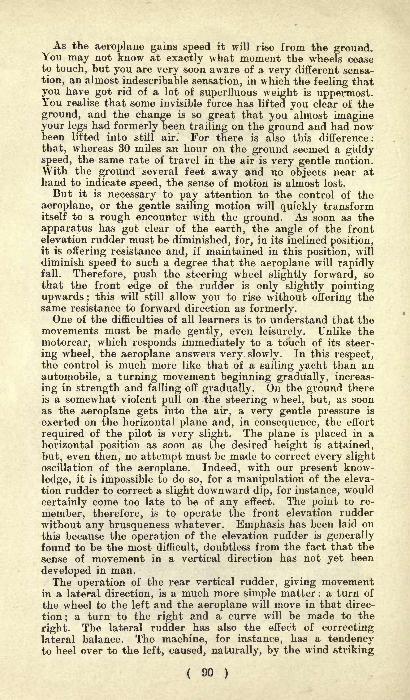
As the aeroplane gains speed it will rise from the ground.You may not know at exactly what moment the wheels ceaseto touch, but you are very soon aware of a very different sensa-
tion, an almost indescribable sensation, in which the feeling thatyou have got rid of a lot of superfluous weight is uppermost.You realise that some invisible force has lifted you clear of the
ground, and the change is so great that you almost imagineyour legs had formerly been trailing on the ground and had nowbeen lifted into still air." For there is also this difference :
that, whereas 30 miles an hour on the ground seemed a giddyspeed, the same rate of travel in the air is very gentle motion.With the ground several feet away and no objects near athand to indicate speed, the sense of motion is almost lost.
But it is necessary to pay attention to the control of the
aeroplane, or the gentle sailing motion will quickly transformitself to a rough encounter with the ground. As soon as the
apparatus has got clear of the earth, the angle of the frontelevation rudder must be diminished, for, in its inclined position,it is offering resistance and, if maintained in this position, will
diminish speed to such a degree that the aeroplane will rapidlyfall. Therefore, push the steering wheel slightly forward, sothat the front edge of the rudder is only slightly pointingupwards; this will still allow you to rise without offering thesame resistance to forward direction as formerly.One of the difficulties of all learners is to understand that the
movements must be made gently, even leisurely. Unlike the
motorcar, which responds immediately to a touch of its steer-
ing wheel, the aeroplane answers very slowly. In this respect,the control is much more like that of a sailing yacht than anautomobile, a turning movement beginning gradually, increas-
ing in strength and falling off gradually. On the ground thereis a somewhat violent pull on the steering wheel, but, as soonas the aeroplane gets into the air, a very gentle pressure is
exerted on the horizontal plane and, in consequence, the effort
required of the pilot is very slight. The plane is placed in ahorizontal position as soon as the desired height is attained,
but, even then, no attempt must be made to correct every slightoscillation of the aeroplane. Indeed, with our present know-
ledge, it is impossible to do so, for a manipulation of the eleva-
tion rudder to correct a slight downward dip, for instance, would
certainly come too late to be of any effect. The point to re-
member, therefore, is to operate the front elevation rudder
without any brusqueness whatever. Emphasis has been laid onthis because the operation of the elevation rudder is generallyfound to be the most difficult, doubtless from the fact that the
sense of movement in a vertical direction has not yet been
developed in man.The operation of the rear vertical rudder, giving movement
in a lateral direction, is a much more simple matter : a turn of
the wheel to the left and the aeroplane will move in that direc-
tion;a turn to the right and a curve will be made to the
right. The lateral rudder has also the effect of correctinglateral balance. The machine, for instance, has a tendencyto heel over to the left, caused, naturally, by the wind striking
( 90 )
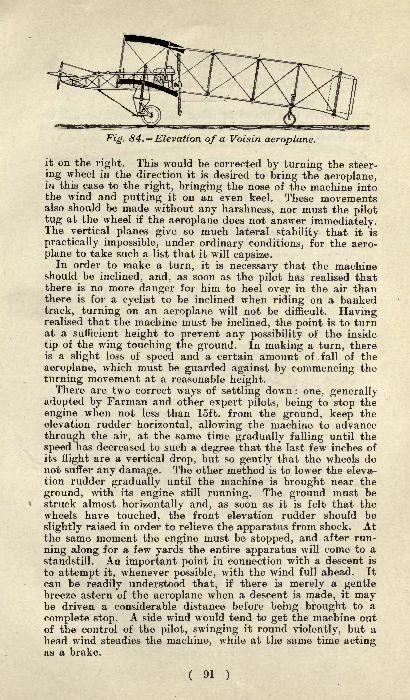
Fig. 84. Elevation of a Voisin aeroplane.
it on the right. This would be corrected by turning the steer-
ing wheel in the direction it is desired to bring the aeroplane,in this case to the right, bringing the nose of the machine intothe wind and putting it on an even keel. These movementsalso should be made without any harshness, nor must the pilottug at the wheel if the aeroplane does not answer immediately.The vertical planes give so much lateral stability that it is
practically impossible, under ordinary conditions, for the aero-
plane to take such a list that it will capsize.In order to make a turn, it is necessary that the machine
should be inclined, and, as soon as the pilot has realised thatthere is no more danger for him to heel over in the air thanthere is for a cyclist to be inclined when riding on a bankedtrack, turning on an aeroplane will not be difficult. Havingrealised that the machine must be inclined, the point is to turnat a sufficient height to prevent any possibility of the inside
tip of the wing touching the ground. In making a turn, thereis a slight loss of speed and a certain amount of fall of the
aeroplane, which must be guarded against by commencing the
turning movement at a reasonable height.There are two correct ways of settling down : one, generally
adopted by Farman and other expert pilots, being to stop the
engine when not less than 15ft. from the ground, keep theelevation rudder horizontal, allowing the machine to advance
through the air, at the same time gradually falling until the
speed has decreased to such a degree that the last few inches of
its flight are a vertical drop, but so gently that the wheels donot suffer any damage. The other method is to lower the eleva-tion rudder gradually until the machine is brought near the
ground, with its engine still running. The ground must bestruck almost horizontally and, as soon as it is felt that thewheels have touched, the front elevation rudder should be
slightly raised in order to relieve the apparatus from shock. Atthe same moment the engine must be stopped, and after run-
ning along for a few yards the entire apparatus will come to a
standstill. An important point in connection with a descent is
to attempt it, whenever possible, with the wind full ahead. It
can be readily understood that, if there is merely a gentlebreeze astern of the aeroplane when a descent is made, it maybe driven a considerable distance before being brought to a
complete stop. A side wind would tend to get the machine outof the control of the pilot, swinging it round violently, but a
head wind steadies the machine, while at the same time actingas a brake.
( 91 )

STREAMLINE FORM.
All bodies that are to be called upon to move through theair should take a form which should prevent, as far as possible,the mutilation of the stream lines. It has been shown by a
Fig. 85. Discontinuity offlow due to the shoulder (a).
study of the form suitable for bullets and for torpedoes andsubmarines (although information about the latter is not readily
Fig. 86. The pressures showing the forces acting on andoutwardfrom a streamline body.]
A is the head of the body, B the shoulder, C the buttock, and D the tail.
available) that a discontinuous flow of the fluid in which the
body is moving must be avoided if that motion is not to be
Fig. 87 . Discontinuity caused by removal of buttock andtail portions.
( 92 )
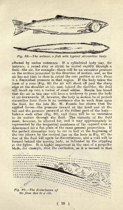
Fig. 88. The salmon, a fish with typical streamline body.
affected by undue resistance. If a cylindrical body (say, for
instance, a round stay or strut) be moved rapidly through afluid the air, for example there will be an excessive pressureon the surface presented to the direction of motion, and, as theair has not time to close in round the rear portion or run, thereis a diminished pressure in that region. If the body takes theform of a cone (Fig. 85) the air will shoot off past the sharpedge at the shoulder at (a), and, behind the shoulder, the fluid
will break up into a vortex of small eddies. Maxim has foundthat the air in this case will have a tendency to press the bodyat (a) downwards. If, however, the body in motion be of perfectstreamline form there is no resistance due to work done uponthe fluid, for the late Mr. W. Froude has shown that the
applied forces the pressure inward at the head and at the
tail and the pressure outward at the fullest part of the bodybalance each other (Fig. 86), and there will be no resistance
to its motion through the fluid. The viscosity of the fluid
must, however, be allowed for, and it may approximately be
represented by the tangential resistance of the exposed area as
determined for a flat plate of the same general proportions. If
the perfect streamline body be cut in half at the beginning of
the run (shown by the vertical line on the body in Fig. 87) the
flow of the fluid will again be discontinuous, and a void will be
formed behind the moving body, as indicated by the stipplingin the figure. It is highly important in the case of a propeller
blade, ^for example, that the cavitation, as it is termed in that
Fig. 89. The disturbance ofthe flow due to a rib.
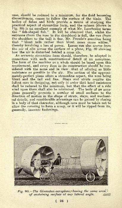
case, should be reduced to a minimum, for the fluid becomingdiscontinuous, ceases to follow the surface of the blade. Thebodies of fishes and birds provide a means of studying the
practical aspect of streamline form, and the salmon (shown in
Fig. 88) is an excellent example of what Mr. Lanchester termsthe "fish-shaped fish." It will be observed that, whilst, theentrance (from the nose to the shoulders) is full, the run (fromthe shoulders to the tail) is fine, Mr. Froude's assertion beingthat " blunt tails rather than blunt noses cause eddies,"thereby involving a loss of power. Losses can also accrue fromthe use of ribs across the surface of a plane, Fig. 89 showinghow the air is disturbed behind a cross rib.
An accurate streamline form should, therefore, be adopted in
connection with each constructional detail of an aeroplane.The form of the machine as a whole should be based upon this
requirement, and every item in its construction should be con-sidered with the same end in view that of offering as little
resistance as possible to the air. The section of the approxi-mately-perfect plane offers a streamline aspect, the nose beingblunt and the tail end fine. Stays and struts require thefullest care in designing, not only in order that head resistance
shall be reduced to the minimum, but that the effect of a side
wind upon them shall also be minimised. The body of an aero-
plane generally presents a number of small surfaces to thedirection of motion in the shape of struts, stays, and mechani-cal details, and considerable advantage can be gained by closingin a body of that character, although care must be taken not to
allow the covering to form a scoop, or it will be ripped from its,
generally, insecure fastenings.
Fig. 90. The Givaudan^aeroplane,Shaving the sameof sustaining surface at any lateral angle.
( 94 )
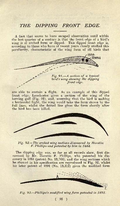
THE DIPPING FRONT EDGE.
A fact that seems to have escaped observation until within
the last quarter of a century is that the front edge of a bird's
wing is of arched form or dipped. This dipped front edge is,
according to those who have of recent years closely studied this
peculiarity, characteristic of the wing form of all birds that
Fig. 91. A section of a typicalbird's wing showing the dipping
front edge.
are able to sustain a flight. As an example of this dippedfront edge, Lanchester gives a section of the wing of the
herring gull (Fig. 91), and, assuming that the bird is makinga horizontal flight, the wing would take the form shown by thefull lines, whilst the dotted line gives the form shortly after
the bird has been killed.
Fig. 92. The arched wing sections discovered by Horatio\F. Phillips and patented by him in 1884.
The dipping edge was, so far as all records show, first dis-
covered by Mr. Horatio F. Phillips, who patented his dis-
covery in 1884 (patent No. 13,768), and the wing sections whichhe showed in his specification are reproduced in Fig. 92, whilsthis later patent of 1891 (No. 13,311) gives the modified form
Fig. 93. Phillips's modified wing form patented in 1891.
( 95 )
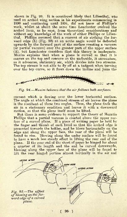
shown in Fig. 93. It is considered likely that Lilienthal, whoused an arched wing section in his experiments commencing in
1890 and continuing until 1894, did not know of Phillips'swork, whilst at about the same time Lanchester evolved thearched form, as he says, from theoretical considerations andwithout any knowledge of the work of either Phillips or Lilien-
thal. Phillips assumed that a current of air striking the for-
ward edge (E) (Fig. 93) at an acute angle would be deflected
upwards by the forward part of the surface creating a vacuum(or partial vacuum) over the greater part of the upper surface
(A), but Laiichester considers that this theory is inadequate.Maxim explains that when a plane is curved so that it is
convex on the top and concave on the underside, it encounters,as it advances, stationary air, which divides into two streams.The top stream is not able to fly off at a tangent when turningover the top curve, so it flows down the incline and joins the
Fig. 94. Maxim believes that the air follows both surfaces.
current which is flowing over the lower horizontal surface.
The angle at which the combined stream of air leaves the planeis the resultant of these two angles. Thus, the plane finds theair in a stationary condition and leaves it with a downwardmotion, so that the plane itself must be lifted.
But there is some evidence to support the theory of Horatio
Phillips that a partial vacuum is created above the upper sur-
face of a curved plane. If a piece of writing paper be held bythe finger and thumb of each hand so that the arched edge is
presented towards the holder, and he blows horizontally on the
edge and along the upper face, the rear of the plane will befound to rise. Blowing along the under surface will be foundto have a much less steady effect in lifting the rear end of the
plane. If the rear end of the sheet of paper be hinged for about
a quarter of its length and the end be curved downwards,
blowing along the upper face of the plane will be found t<?
lift the rear hinged portion almost vertically in the air and
UF7JXG ACTION
Fig. 95. The effect
of blowing on the for-ward edge of a curved
plane.
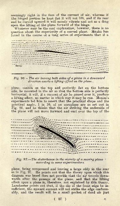
seemingly right in the face of the current of air, whereas if
the hinged portion be kept flat it will not lift, and if its rear
end be curved upward it will merely vibrate and act as a dragupon the lifting of the plane forward of the hinge.Whatever may be the real explanation, however, there is no
question about the superiority of a curved plane. Maxim has
found in the course of a long series of experiments that if a
Fig. 96. The air leaving both sides of a plane in a downwarddirection exerts a lifting effect on the plane.
plane, convex on the top and perfectly flat on the bottomside, be mounted in the air so that the bottom side is perfectlyhorizontal, it will, if a current of air be passed over it, producea lifting effect, no matter in which way it may be run. Maxim's
experiments led him to assert that the practical shape and the
practical angle, 1 in 10, of an aeroplane are as set out in
Fig. 96, and he thinks that the air striking the underside ofthe plane will not move forward and curl over the top of the
Fig. 97. The disturbance in the vicinity of a moving plane \
according to some experimenters.
plane, being compressed and leaving a large eddy in the rearas in Fig. 97. He points out that the theory upon which this
diagram was based does not provide that the air travels down-wards after the passage of the plane, and that the liftingeffect upon a plane is, therefore, not explained by this theory.Lanchester points out that, if the dip of the front edge be in-
sufficient, the upward current will not strike the edge conform-
ably, and the result will be a small pocket of dead air just
( 97 ) G
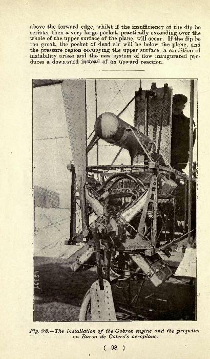
above the forward edge, whilst if the insufficiency of the dip be
serious, then a very large pocket, practically extending over thewhole of the upper surface of the plane, will occur. If the dip betoo great, the pocket of dead air will be below the plane, andthe pressure region occupying the upper surface, a condition of
instability arises and the new system of flow inaugurated pro-duces a downward instead of an upward reaction.
JPig. 98. The installation of the Gobron engine and the propelleron Baron de Caters's aeroplane.
GLIDING AS A SPORT.
How to Construct a Glider. Instructions for
Learning to Glide.
There is an exhilaration about gliding which cannot beobtained in any other sport. The sense of floating through the
air, of being of the earth but above it, of conquering a barrierthat Nature had for centuries drawn against man, gives a
feeling of exultation and delight that can be found in no other
pursuit of pleasure. There is also in gliding a splendid schoolfor the training of quick judgment, of calm reflection but rapiddecision, and of precision of movement, which stimulate thebrain and develop those qualities which flag in our modernlife. And with the work that comes from the necessity of carry-ing the machine again and again to the top of the hill, or, asChanute once put it, winding up the gravity spring, there is
all the exercise associated with other out-door sports.In gliding there is no danger, if one be not ridiculously im-
prudent, and provided one is strong enough to suffer a fewshocks without hurt. The art must be learnt in easy stages,caution being the insurance against harm. And who, in trust-
ing himself to the element which since the beginning of theworld has seemed, and even now seems, to defy man's skill andingenuity, will not proceed warily? No man who cannot swimwould throw himself into an unfordable stream, expecting toreach the other side. He would first set himself to master the
ability to progress a few feet through the water, and by gradualstages learn to swim. So must it be with gliding. A few feetat first
;then further and gradually further
; until, with intelli-
gent and capable control of the machine a glide of a hundredfeet or more can be taken. From Wilbur Wright's lecture of
1901 and from the later one of 1903, both read before theWestern Society of Engineers, let a lesson be taken in caution.If ever there were men who exercised patience and self-restraint
they were the Wright brothers during the experiments that ledthem to the conquest of the air by mechanical flight. Im-patience, rashness, and precipitation are of the very essence of
peril, whilst, on the other hand, calmness, self-possession,
patience and self-restraint will carry the gliding devotee safelyand unscathed through thousands of flights.
Beyond those who will indulge in gliding as the nearest
approach that their purse permits to controlled flight, everyonewho takes to aeroplaning should previously indulge in a courseof glides. The present-day great masters of flight, the Wrights,Farman and the Voisins, have learnt their elementary notionsof equilibrium in the air from gliding experiments. Chanute,with his assistant, Herring (whose work has not yet been
99 G2

accomplished), Capt. Ferber, Archdeacon, and others have prac-tised the art, not primarily for sport sake, though enjoying the
sport, but for education and instruction.
The first and ruling qualification for the sport of gliding is the
accessibility to a suitable slope. The ground should be open
Fig. 99. Plan of glider, giving dimensions of tail and width
of main planes.
and free from trees, with no bushes or gorse heather does notmatter to cause obstruction when alighting. Heather, in fact,is an advantage, just as sand is, because of the "
cushioning"
it affords should a glide be prematurely terminated. Howsmoothly the glider comes to ground at the natural terminationof a flight can be gathered from the fact that the Wrightsassumed a prone position during all their gliding trials. Theslope should be from 1 in 10 to 1 in 7, and should be from 150ft.
to 300ft. or 400ft. long. Such slopes are not to be found in
many parts, and it should therefore be the first concern of thewould-be gliding exponent to discover a suitable ground, whichshould also be at least 150ft. wide. Trees in the proximity donot matter, if they are planted in regular order, and if themachine does not approach them too closely.For the novice no better material will be found for the frame-
work than bamboo, which can be obtained selected for the job.In respect of its section, it is not all that can be desired for thereduction of wind resistance, but this is not of much importanceat the speeds which the glider attains. Providing strength with
lightness, bamboo possesses the additional advantage that it
requires no working. It is ready for use in the state in which it
( 100 )
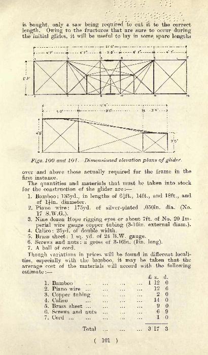
is bought, only a saw being required to cut it to the correct
length. Owing to the fractures that are sure to occur duringthe initial glides, it will be useful to lay in some, spare lengths
Figs. 100 and 101. Dimensioned elevation plans of glider.
over and above those actually required for the frame in the
first instance.
The quantities and materials that must be taken into stock
for the construction of the glider are :
1. Bamboo: 135yd., in lengths of 6ft., 14ft., and 18ft., andof Ijin. diameter.
2. Piano wire: 175yd. of silver-plated .056in. dia. (No.17 S.W.G.).
3. Nine dozen Hope rigging eyes or about 7ft. of No. 20 Im-
perial wire gauge copper tubing (3-16in. external diam.).4. Calico: 25yd. of double width.5. Brass sheet: 1 sq. yd. of 24 B.W. gauge.6. Screws and nuts: a gross of 3-16in. (lin. long).7. A ball of cord.
Though variations in prices will be found in different locali-
ties, especially with the bamboo, it may be taken that the
average cost of the materials will accord with the followingestimate :
s. d.
1. Bamboo ... 1 12
2. Piano wire ... ... ... ... 12 6
3. Copper tubing 204. Calico 14
5. Brass sheet ... ... 906. Screws and nuts ... ... ... 697. Cord . 1
Total .,.
( 101 )
3 17 3
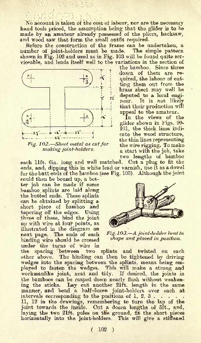
Fig. 102. Sheet metal as cutformaking joint-holders.
No account is taken of the cost of labour, nor are the necessaryhand tools priced, the assumption being that the glider is to be
made by an amateur already possessed of the pliers, hacksaw,and wood saw that form the small outfit required.
Before the construction of the frame can be undertaken, anumber of joint-holders must be made. The simple patternshown in Fig. 102 and used as in Fig. 103 will be found quite ser-
viceable, and lends itself well to the variations in the section of
the bamboo. Since threedozen of them are re-
quired, the labour of cut-
ting them out from thebrass sheet may well be
deputed to a local engi-neer. It is not likelythat their production will
appeal to the amateur.In the views of the
glider shown in Figs. 99-
101, the thick lines indi-
cate the wood structure,the thin lines representingthe wire rigging. To makea start with the job, taketwo lengths of bamboo
each lift. Gin. long and well matched. Cut a plug to fit the
ends, and, dipping this in white lead or varnish, use it as a dowelfor the butt ends of the bamboo (see Fig. 105). Although the jointcould then be bound up, a bet-
ter job can be made if some
bamboo, splints are laid alongthe butted ends. These splintscan be obtained by splitting ashort piece of bamboo and
tapering off the edges. Usingthree of these, bind the joint
up with wire at four points, as
illustrated in the diagram onnext page. The ends of each
binding wire should be crossed
under the turns of wire in
the spacing between two splints and twisted on eachother above. The binding can then be tightened by drivingwedges into the spacing between the splints, means being em-
ployed to fasten the wedges. This will make a strong andworkmanlike joint, neat and tidy. If desired, the joints in
the bamboos can be rasped down nearly flush without weaken-
ing the sticks. Lay out another 21ft. length in the samemanner, and bend a half-dozen joint-holders over each atintervals corresponding to the positions of 1, 2, 3
11, 12 in the drawings, remembering to turn the lap of the
joint towards the inside. Cut a dozen lengths of 5ft., and,
laying the two 21ft. poles on the ground, fit the short pieces
horizontally into the joint-holders. This will give a stiffened
Fig. 103. A joint-holder bent to
shape and placed in position.
( 102 )
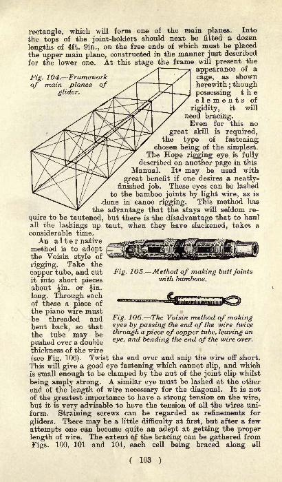
rectangle, which will form one of the main planes. Into
the tops of the joint-holders should next be fitted a dozen
lengths of 4ft. 9in., on the free ends of which must be placedthe upper main plane, constructed in the manner just described
for the lower one. At this stage the frame will present the
s\ a appearance of a
Fig. 104. Framework // / cage, as shown
of main planes ofglider.
herewith ; thoughpossessing theelements of
rigidity, it will
need bracing.Even for this no
great skill is required,the type of fastening
chosen being of the simplest.The Hope rigging eye. is fully
described on another page in this
Manual. It* may be used with
great benefit if one desires a neatly-finished job. These eyes can be lashed
to the bamboo joints by light wire, as is
done in canoe rigging. This method hasthe advantage that the stays will seldom re-
quire to be tautened, but there is the disadvantage that to haulall the lashings up taut, when they have slackened, takes aconsiderable time.
An alter nativemethod is to adoptthe Voisin style of
rigging. Take the
copper tube, and cutit into short piecesabout ^in. or fin.
long. Through eachof these a piece of
the piano wire mustbe threaded andbent back, so thatthe tube may be
Fig. 105. Method of making butt joints"with bamboos.
Fig. 106. The Voisin method of makingeyes by passing the end of the wire twice
through a piece of copper tube, leaving an
eye, and bending the end of the wire over.pushed over a doublethickness of the wire
(see Fig. 106). Twist the end over and snip the wire off short.
This will give a good eye fastening which cannot slip, and whichis small enough to be clamped by the nut of the joint clip whilst
being amply strong. A similar eye must be lashed at the other
end of the length of wire necessary for the diagonal. It is notof the greatest importance to have a strong tension on the wire,but it is very advisable to have the tension of all the wires uni-
form. Straining screws can be regarded as refinements for
gliders. There may be a little difficulty at first, but after a few
attempts one can become quite an adept at getting the properlength of wire. The extent of the bracing can be gathered from
Figs. 100, 101 and 104, each cell being braced along all
( 103 )

diagonals, and the frames of the main planes stiffened, asshown in the plan view. If supported at its outer ends, thisskeleton structure is capable of supporting a load of about3cwt. in the centre.
In the construction of the tail, exactly the same procedure is
to be followed. The spread being 6ft. 6in., four pieces of this
length must be sawn off, and there will also be required six
lengths of 2ft. Sin. for the vertical members and six lengths of
3ft. 4in. to serve as fore-and-aft members. The same patternof joint-holder being available as in the building of the mainplanes, the completion of the tail will offer no difficulties. Forits attachment to the supporting planes, four rods, 18ft. in
length, must be used. These are laced between the bamboostruts of the main planes and tail, as depicted in Fig. 101, andare then lashed with wire drawn tightly round the struts andmain poles. By rigging diagonal wires across top and bottomand across both sides, the entire frame of the glider will berendered quite rigid.Both the main planes have to be covered completely with
calico, except for the space between the points 9 and 10 (see
Fig. 100) on the lower plane. This space, which corresponds to
the joints in the main poles, is required for the aviator, whosupports himself on two bearers set at the most convenientdistance apart and lashed at both ends to the main poles. Thecalico must be turned over the bamboo members and stitched in
place after it has been drawn up as tightly .as possible. Thetail also needs to be covered with the same material, but in this
case there are also three vertical panels to be added, as shownin the rear elevation of the glider. If necessary, the calico
can be shrunk by one or two coats of starch paste.Trials can be made in a steady wind, that is strong enough
to lift the glider when it is held by one of the front cross-poles.In the initial glides it is essential to have the assistance of
two men. For this purpose two cords, about 6ft. in length,should be attached to the forward extremities of the lower main
plane, and these should be held by the assistants, one at eachend. Having determined the direction of the wind, face it,
place yourself in the glider, with the supports under
your arms, and give the order to start down the slopeat a moderate pace. At the end of a few steps the gliderwill lift the passenger from the ground, but the assistants
should continue to run right down the slope, keeping the cords
in their hands. Caution is most advisable and it should not beuntil at least a dozen captive glides have been made that anaviator should attempt a free glide, and even then only if
he feels perfect confidence in his ability to control the machine.To steer to the right, throw the legs to the right ;
to steer to
the left, throw them to the left;to alight, bring the weight of
the body further forward. At first there will be a tendency to
keep the body too far back. This must be strongly combated,for it is the only position that is dangerous. During the captive
glides, the effect of various movements of the body must be
closely watched, for upon them depends the control of the
machine. When these details have been mastered, a short free
( 104 )
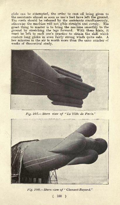
glide can be attempted, the order to cast off being given to
the assistants almost as soon as one's feet have left the ground.The cords should be released by the assistants simultaneously,otherwise the machine will not glide straight and evenly. The
great thing to master is to bring the machine smoothly to the
ground by stretching the legs forward. With these hints, it
must be left to each one's practice to obtain the skill whichrenders long glides in even fairly strong winds quite safe. Afew minutes in the air is worth more than the same number of
weeks of theoretical study.
Fig. 107. Stern view of "La Ville de Paris."
Fig. 108. Stern view of"Clement-Bayard."
( 105 )
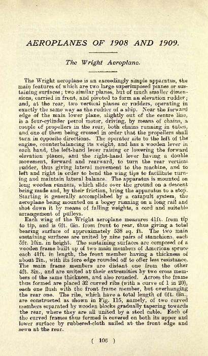
AEROPLANES OF 1908 AND 1909.
The Wright Aeroplane.
The Wright aeroplane is an exceedingly simple apparatus, the
main features of which are two large superimposed planes or sus-
taining surfaces;two similar planes, but of much smaller dimen-
sions, carried in front, and pivoted to form an elevation rudderj
and, at the rear, two vertical planes or rudders, operating in
exactly the same way as the rudder of a ship. Near the forward
edge of the main lower plane, slightly out of the centre liny,
is a four-cylinder petrol motor, driving, by means of chains, a
couple of propellers in the rear, both chains running in tubes,and one of them being crossed in order that the propellers shall
turn in opposite directions. The operator sits to the left of the
engine, counterbalancing its weight, and has a wooden lever in
each hand, the left-hand lever raising or lowering the forwardelevation planes, and the right-hand lever having a double
movement, forward and rearward, to turn the rear vertical
rudder, thus giving lateral movement to the machine, and to
left and right in order to bend the wing tips to facilitate turn-
ing and maintain lateral balance. The apparatus is mounted on
long wooden runners, which slide over the ground on a descent
being made and, by their friction, bring the apparatus to a stop.
Starting is generally accomplished by a catapult system, the
aeroplane being mounted on a bogey running on a long rail andshot down it by means of falling weights, a cord and suitable
arrangement of pulleys.Each wing of the Wright aeroplane measures 41ft. from tip
to tip, and is 6ft. Gin. from front to rear, thus giving a total
bearing surface of approximately 538 sq. ft. The two main
sustaining surfaces are united by nine pairs of stanchions, each5ft. lOin. in height. The sustaining surfaces are composed of a
wooden frame built up of two main members of American spruceeach 41ft. in length, the front member having a thickness of
about 2in., with its fore edge rounded off to offer less resistance.
The main frame members are distant one from the other
4ft. 3in., and are united at their extremities by two cross mem-bers of the same thickness, and also rounded. Across the framethus formed are placed 32 curved ribs (with a curve of 1 in 20),
each one flush with the front frame member, but overhangingthe rear one. The ribs, which have a total length of 6ft. 6in.,
are constructed as shown in Fig. 115, namely, of two curvedmembers separated by wooden blocks gradually tapering towardsthe rear, where they are all united by a steel cable. Each of
the curved frames thus formed is covered on both its upper andlower surface by rubbered-cloth nailed at the front edge andsewn at the rear.
( 106 )
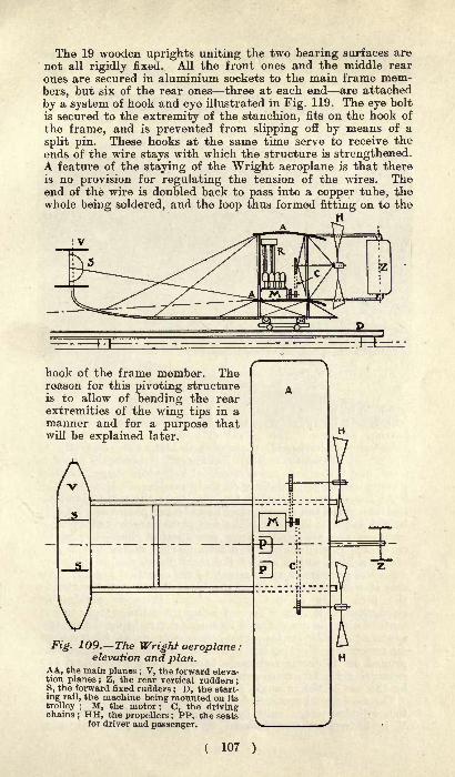
The 19 wooden uprights uniting the two bearing surfaces are
not all rigidly fixed. All the front ones and the middle rear
ones are secured in aluminium sockets to the main frame mem-bers, but six of the rear ones three at each end are attached
by a system of hook and eye illustrated in Fig. 119. The eye bolt
is secured to the extremity of the stanchion, fits on the hook of
the frame, and is prevented from slipping off by means of a
split pin. These hooks at the same time serve to receive the
ends of the wire stays with which the structure is strengthened.A feature of the staying of the Wright aeroplane is that thereis no provision for regulating the tension of the wires. Theend of the wire is doubled back to pass into a copper tube, thewhole being soldered, and the loop thus formed fitting on to the
hook of the frame member. Thereason for this pivoting structureis to allow of bending the rearextremities of the wing tips in amanner and for a purpose thatwill be explained later.
A
VFig. 109. The Wright aeroplane :
elevation and plan.AA, the main planes ; V, the forward eleva-tion planes ; Z, the rear vertical rudders ;
S, the forward fixed rudders ; D, the start-
ing rail, the machine being mounted on its
trolley ; M, the motor ; C, the drivingchains ; HH, the propellers ; PP, the seats
for driver and passenger.
( 107 )
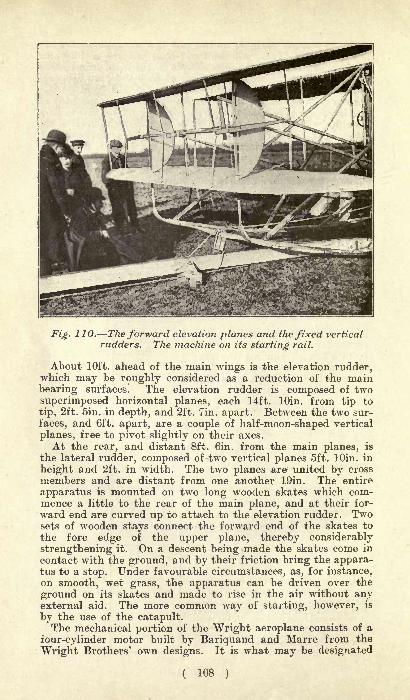
Fig. 110. The forward elevation planes and the fixed vertical
rudders. The machine on its starting rail.
About 10ft. ahead of the main Avings is the elevation rudder,which may be roughly considered as a reduction of the mainbearing surfaces. The elevation rudder is composed of two
superimposed horizontal planes, each 14ft. lOin. from tip to
tip, 2ft. Sin. in depth, and 2ft. Tin. apart. Between the two sur-
faces, and 6ft. apart, are a couple of half-moon-shaped vertical
planes, free to pivot slightly on their axes.
At the rear, and distant 8ft. Gin. from the main planes, is
the lateral rudder, composed of two vertical planes 5ft. lOin. in
height and 2ft. in width. The two planes are united by cross
members and are distant from one another 19in. The entire
apparatus is mounted on two long wooden skates which com-mence a little to the rear of the main plane, and at their for-
ward end are curved up to attach to the elevation rudder. Twosets of wooden stays connect the forward end of the skates to
the fore edge of the upper plane, thereby considerably
strengthening it. On a descent being made the skates come in
contact with the ground, and by their friction bring the appara-tus to a stop. Under favourable circumstances, as, for instance,on smooth, wet grass, the apparatus can be driven over the
ground on its skates and made to rise in the air without anyexternal aid. The more common way of starting, however, is
by the use of the catapult.The mechanical portion of the Wright aeroplane consists of a
four-cylinder motor built by Bariquand and Marre from the
Wright Brothers' own designs. It is what may be designated
( 108 )

a medium-weight motor : not so light as the special aeroplane
engines recently developed in France, buti considerably lighterthan the standard car engine, which it resembles in all mainfeatures of design. The engine is carried near the forward edgeof the lower plane, but about 2ft. to the right of the longitudinalcentre. The pilot occupies a seat to the left of the engine, thus
counterbalancing its weight; the passenger's seat is between
the pilot and the engine and almost in the centre line of the
plane. Thus, whether a passenger is carried or not, the lateral
Fig. 111. Rear view showing engine, propellers, and trans-
mission. The skates are also clearly seen.
balance of the aeroplane is not disturbed. The engine drives a
couple of wooden propellers in the rear; those generally em-
ployed have a diameter of 8ft. 3in., and are geared 33 to 9,
giving 450 propeller revolutions a minute. In this respect the
Wright machine differs from most of the French machines,where the propeller is mounted direct on the engine shaft, andturns at from 1,100 to 1,500 revolutions a minute. During the
1908 trials in France, the propellers and the gearing were fre-
quently changed, the longest flights being made with propellersof 9ft. 2in. diameter.The supply of cooling water for the engine is contained in a
radiator composed of plain, flat copper tubes attached to oneof the forward stanchions of the aeroplanes. The quantity of
water carried is a little over two gallons. The petrol supplyis contained in a cylindrical reservoir, at first placed horizon-
tally, but now hung vertically between the two main planes.The flow is by gravity to the petrol pump within the crankcase,from which the petrol is directly injected into the cylinders.
It has already been stated that, under favourable circum-
stances, the aeroplane can be started from the ground on its
( 109 )
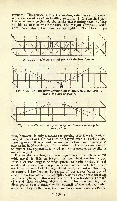
runners. The general method of getting into the air, however,is by the use of a rail and falling weights. It is a method thathas been much criticised, the critics maintaining that, so longas this apparatus was necessary, the Wright aeroplane couldnever be employed for cross-country flights. The catapult sys-
Fig. 112. The struts and stays of the latestform.
Fig. 113. The primary warping mechanism -with its lever to
warp the upper plane.
Fig. 114. The secondary warping mechanism to warp the
lower plane.
tern, however, is only a means for getting into the air, and, so
long as operations are confined to flights over a specially-pre-
pared ground, it is a most convenient method, and one that is
successful in 99 starts out of a hundred. It will be soon enoughto burden the apparatus with wheels when cross-country flights
are attempted.The wooden starting rail, the upper face of which is bound
with metal, is 68ft. in length. A two-wheel wooden bogey,formed of two lengths of wood placed at right angles, is laid
on it and receives the aeroplane, which, immediately before the
start, is supported at the right-hand tip by a trestle;this side,
of course, being heavier by reason of the motor being out of
centre. To the rear of the aeroplane, as it rests on the starting
rail, is a pylone, to the summit of which are hoisted a numberof metal discs weighing about 14cwt. The rope securing the
discs passes over a pulley at the summit of the pylone, underanother pulley at the base, then travels forward underneath the
( 110 )

Fig. 115 Showing construction of one of the curved ribs
formingframework of the main wings to be coveredwith rubbered cloth on both surfaces.
aeroplane to a pulley at the extremity of the rail, returning
along the rail to the aeroplane, to which it is attached by meansof a hook.When the aeroplane has been placed in position on its rail,
and the weights mounted, it is temporarily attached in the
manner shown in Fig. 116. Here the pilot's seat is shown at S;
beneath him is a bar (A), hinged at B, and secured in a notch of
the plate (P).Around the bar (A)is a short wirecable secured to the
starting rail.
The engine havingbeen started andthe trestle underthe extremity of
the wing replacedby an attendant,the pilot leans for-
ward and pulls thebar (P) out of en-
gagement with A,with the result thatthis latter falls, thecable (C) slips overits end, and the
aeroplane is free to shoot down the rail. Under the combinedinfluence of the falling weights and the revolving propellers, the68ft. of the rail are covered in 3fsec., which gives a speed at theend of the rail which may be estimated at 35 miles an hour.While running down the rail, the front elevation rudder hasbeen kept in 'a position to hold the aeroplane down, and it is
only as the end of the rail is reached that it is raised and the
apparatus rises somewhat rapidly into the air to perform its
wonderful evolutions.
The pilot has to operate two different steering levers in orderto preserve the machine at 'the right altitude, to maintain longi-tudinal and lateral balance and to make his turns. He has, in
no way, to occupy himself with the engine, which is indeed un-
provided with any other control than an appliance for relieving
Fig. 116. The method of attaching the
aeroplane to the starting rail, andof releasing it.

the compression, and so stopping, when it is desired to descend.The point of ignition is fixed, the throttle does not exist, for the
supply of petrol is mechanical, and lubrication is assured by a
pump.The lever in the pilot's left hand has a simple movement for-
ward and backward. If pulled towards the pilot, the frontelevation planes are slightly raised, and the tendency of the
aeroplane is to rise to a higher altitude. If pushed ahead, thetwo planes are made to point towards the ground, and thedirection of the aeroplane is then downwards. Reference to
Fig. 11 7. Frontelevation rudderand its method ofcontrol. The lever
F is held in the
pilot's left hand.
Fig. 117 shows how these movements are obtained. F is the eleva-
tion lever pivoting at G, and having attached to it, by a bolt,the bar (A,) connected up to the short lever (B) and controllingthree connecting rods (C), operating on the tubes (D) and in-
clining the planes. When the operating lever (F) is in its normal
position the elevation planes have a slight curve, but by reasonof the difference of length between the front and the rear por-tions of the connecting rod (C), as well as the front and the rear
portions of the planes, when the lever is carried full ahead therear of the planes are carried upwards, as shown in the dottedline. When the lever is brought to the rear the forward edge of
the planes is raised but slightly and the rear is fully lowered.The control of this elevation rudder is first given to pupils learningto handle the machine. Whenever the aeroplane has a tendencyto dive the lever is pulled back; if the machine is going too
high the rudder is pushed forward. The movement is onlyslight, and is very difficult to follow by an observer on land.
The right-hand lever is more complicated in its operation, andmore difficult to manoeuvre than the one just described. It hastwo distinct movements forward and backward and to left
and right. If the lever is merely carried ahead it will direct thevertical rudder over to the left, and cause the aeroplane to turnto the left. How this is accomplished will be immediately under-stood by reference to Fig. 118, in which A is the right-hand lever,B the forked end connecting rod, C the pivoting crossbar, and
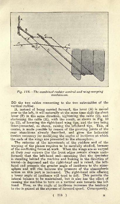
Fig. 11 8. The combined rudder control and -wing-warpingmechanism.
DD the two cables connecting to the two extremities of the
vertical rudder.
If, instead of being carried forward, the lever (A) is movedover to the left, it will naturally at the same time shift the short
lever (F) in the same direction, tightening the cable (G), and
slackening the cable (H), with the result, as shown in Fig. 13
(p. 21), of lowering the right-hand wing tips, and the two beinginter-connected, as shown, raising the left-hand tips. This, of
course", is made possible by reason of the pivoting joints of the
rear stanchions already described, and gives the helicoidal
torsion necessary for modifying the angles of incidence at whichthe ends of the wings are presented to the atmosphere.
The outcome of the movements of the rudders and of the
warping of the planes requires to be carefully studied, becauseof the conflicting forces at work. When the wings are so warpedat their rear corners (for the front edges remain always unde-
formed) that the left-hand end assuming that the spectatoris standing behind the machine and looking in the direction of
travel is depressed and the right-hand end is raised, the left-
hand end presents the greater angle of incidence to the atmo-
sphere and will rise because the pressure of the atmosphericaction on this part is increased. The right-hand side offeringa lesser angle of incidence will tend to fall. This permits thelateral balance to be maintained, but it also has the effect of
causing the machine to turn on a vertical axis towards the left
hand. Thus, as the angle of incidence increases the tendencyto rise is gained at the expense of forward speed. Consequently,
( 113 )

if the angle of incidence on one side is increased and, on the
other, decreased, the machine will tend to slow down on theoutside of the curve and thus produce opposition to the desired
turning movement. To overcome this action the rear rudderis employed in combination with a fixed rudder forward of thecentre of gravity, the Wright patents covering also a pair of
rudders, one forward and one at the rear, operated simul-
taneously. The Wright patents also cover a pair of vertical
vanes, one at each end of the machine and situated betweenthe horizontal planes. These vanes are each mounted on avertical shaft, which has a pulley at its lower end, and theseshafts are connected up by cables with the steering apparatusso that they can be turned to oppose the secondary movementswhich tend to become produced.
Fig. 119. Con-structional "work
on the Wrightaeroplane, show-
ing method ofhinging struts andof securing eyesof stays.
The quick-turning movement of the Wright machine is oneof its distinctive features, and is in strong contrast to the
slow-turning ability of almost all French machines. Naturally,a very wide turn can be made on the Wright machine by thevertical rudder only, but in practice the wings are alwaysflexed a slight degree at the same time.
In reality, turning is only a secondary object of the flexingof the wing tips, the most important being to maintain lateral
balance. In such an unstable element as the air the aeroplanehas a constant tendency to oscillate in all directions. The
tendency to plunge or rear is corrected by the manipulation of
the elevation rudder through the left-hand lever;the tendency
to roll is overcome by the flexing of the wing tips. Should the
aeroplane take a list towards the left, the vertical rudderwould at the same time be inclined
;if it is brought back to a
vertical position this tendency would be corrected. The con-
trary, of course, applies if the heeling movement of the aero-
plane is towards the right.
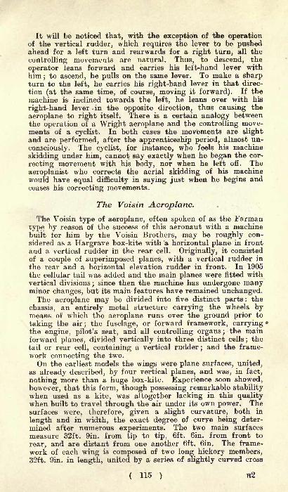
It will be noticed that, with the exception of the operationof the vertical rudder, which requires the lever to be pushedahead for a left turn and rearwards for a right turn, all the
controlling movements are natural. Thus, to descend, the
operator leans forward and carries his left-hand lever with
him; to ascend, he pulls on the same lever. To make a sharpturn to the left, he carries his right-hand lever in that direc-
tion (at the same time, of course, moving it forward). If the
machine is inclined towards the left, he leans over with his
right-hand lever .in the opposite direction, thus causing the
aeroplane to right itself. There is a certain analogy betweenthe operation of a Wright aeroplane and the controlling move-ments of a cyclist. In both cases the movements are slightand are performed, after the apprenticeship period, almost un-
consciously. The cyclist, for instance, who feels his machine
skidding under him, cannot say exactly when he began the cor-
recting movement with his body, nor when he left off. The
aeroplanist who corrects the aerial skidding of his machinewould have equal difficulty in saying just when he begins andceases his correcting movements.
The Voisin Aeroplane.
The Voisin type of aeroplane, often spoken of as the Farmantype by reason of the success of this aeronaut with a machinebuilt for him by the Voisin Brothers, may be roughly con-
sidered as a Hargrave box-kite with a horizontal plane in front
and a vertical rudder in the rear cell. Originally, it consisted
of a couple of superimposed planes, with a vertical rudder in
the rear and a horizontal elevation rudder in front. In 1905the cellular tail was added and the main planes were fitted withvertical divisions
;since then the machine has undergone many
minor changes, but its main features have remained unchanged.The aeroplane may be divided into five distinct parts: the
chassis, an entirely metal structure carrying the wheels bymeans of which the aeroplane runs over the ground prior to
taking the air; the fuselage, or forward framework, carryingthe engine, pilot's seat, and all controlling organs; the mainforward planes, divided vertically into three distinct cells
;the
tail or rear cell, containing a vertical rudder;and the frame-
work connecting the two.
On the earliest models the wings were plane surfaces, united,as already described, by four vertical planes, and was, in fact,
nothing more than a huge box-kite. Experience soon showed,
however, that this form, though possessing remarkable stabilitywhen used as a kite, was altogether lacking in this qualitywhen built to travel through the air under its own power. Thesurfaces were, therefore, given a slight curvature, both in
length and in width, the exact degree of curve being deter-
mined after numerous experiments. The two main surfaces
measure 32ft. 9in. from tip to tip, 6ft. Gin. from front to
rear, and are distant from one another 6ft. 6in. The frame-
work of each wing is composed of two long hickory members,32ft. 9in. in length, united by a series of slightly curved cross
( 115 ) H2
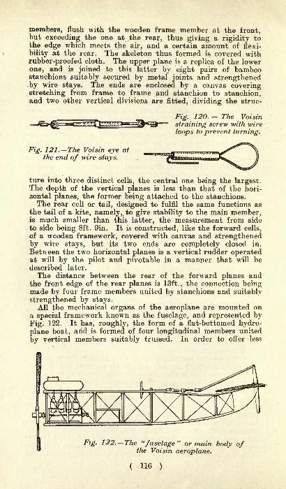
members, flush with the wooden frame member at the front,but exceeding the one at the rear, thus giving a rigidity tothe edge which meets the air, and a certain amount of flexi-
bility at the rear. The skeleton thus formed is covered with
rubber-proofed cloth. The upper plane is a replica of the lower
one, and is joined to this latter by eight pairs of bamboostanchions suitably secured by metal joints and strengthenedby wire stays. The ends are enclosed by a canvas coveringstretching from frame to frame and stanchion to stanchion,and two other vertical divisions are fitted, dividing the struc-
3iFig. 120. The Voisin
straining screw with wire
loops to prevent turning.
Fig. 121. The Voisin eye at
the end of wire stays.
ture into three distinct cells, the central one being the largest.The depth of the vertical planes is less than that of the hori-
zontal planes, the former being attached to the stanchions.The rear cell or tail, designed to fulfil the same functions as
the tail of a kite, namely, to give stability to the main member,is much smaller than this latter, the measurement from side
to side being 8ft. 9in. It is constructed, like the forward cells,
of a wooden framework, covered with canvas and strengthenedby wire stays, but its two ends are completely closed in.
Between the two horizontal planes is a vertical rudder operatedat will by the pilot and pivotable in a manner that will bedescribed later.
The distance between the rear of the forward planes andthe front edge of the rear planes is 13ft., the connection beingmade by four frame members united by stanchions and suitably
strengthened by stays.All the mechanical organs of the aeroplane are mounted on
a special framework known as the fuselage, and represented byFig. 122. It has, roughly, the form of a flat-bottomed hydro-
plane boat, and is formed of four longitudinal members united
by vertical members suitably trussed. In order to offer less
Fig. 122. The "fuselage" or main body ofthe Voisin aeroplane.
( H6 )

Fig. 123. The rear of the "fuselage"of the Voisin aeroplane.
resistance to advancement, the framework is covered with rub-bered cloth. The fuselage may be regarded as the main frame-work of the aeroplane, for to it are attached the fixed wingsand the chassis carrying the wheels, while, mounted at its rear,is the engine and propeller and, immediately in front of this,the pilot's seat. At the front of the fuselage is the elevation
rudder, consisting of two horizontal planes, each 6ft. Gin. inwidth and 3ft. from front to rear, pivoted as shown in Fig. 122,so as to vary the angle of inclination and determine the rise
and fall of the aeroplane.The chassis is an entirely metal structure mounted on pneu-
matic-tyred wire wheels and secured to the fuselage. It is
fitted with powerful shock absorbers, and the wheels aremounted in the same way as castors, being free to turn in anydirection. This is necessary to prevent breakage when landing,a fixed wheel always buckling up, whereas these " orientable "
wheels, as the French term them, allow of settling down without
any damage. Henry Farman has made over 300 descents withthis type of wheel without a single breakage. The tail of the
apparatus is also fitted with a pair of wheels, free to turn in
any direction, of much lighter construction than those in front,their only work being to keep the rear cell from touching the
ground.A single steering wheel, mounted at the extremity of an
almost horizontal steering column, controls all the movements of
the Voisin biplane. It carries a drum A (Fig. 124) round whichis wound a flexible wire cable carried along the frame membersto the rear vertical rudder. Thus, a turn of the steering wheel
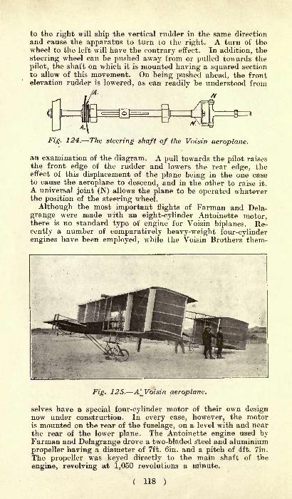
to the right will ship the vertical rudder in the same directionand cause the apparatus to turn to the right. A turn of thewheel to the left will have the contrary effect. In addition, the
steering wheel can be pushed away from or pulled towards the
pilot, the shaft on which it is mounted having a squared section
to allow of this movement. On being pushed ahead, the frontelevation rudder is lowered, as can readily be understood from
/A-
Fig. 124. The steering shaft of the Voisin aeroplane.
an examination of the diagram. A pull towards the pilot raisesthe front edge of the rudder and lowers the rear edge, theeffect of this displacement of the plane being in the one caseto cause the aeroplane to descend, and in the other to raise it.
A universal joint (N) allows the plane to be operated whateverthe position of the steering wheel.
Although the most important flights of Farman and Dela-
grange were made with an eight-cylinder Antoinette motor,there is no standard type of engine for Voisin biplanes. Re-cently a number of comparatively heavy-weight four-cylinderengines have been employed, while the Voisin Brothers them-
Fig. 125. A* Voisin aeroplane.
selves have a special four-cylinder motor of their own designnow under construction. In every case, however, the motoris mounted on the rear of the fuselage, on a level with and near
the rear of the lower plane. The Antoinette engine used byFarman and Delagrange drove a two-bladed steel and aluminium
propeller having a diameter of 7ft. Gin. and a pitch of 4ft. Tin.
The propeller was keyed directly to the main shaft of the
engine, revolving at 1,050 revolutions a minute.
( 118 )
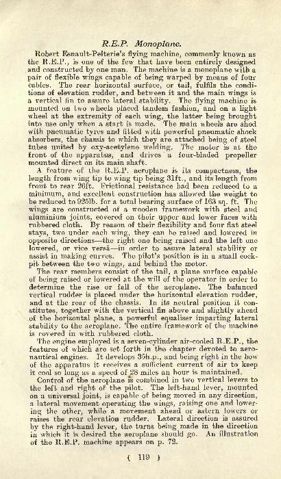
R.E.P. Monoplane.Robert Esnault-Pelterie's flying machine, commonly known as
the R.E.P., is one of the few that have been entirely designedand constructed by one man. The machine is a monoplane with a
pair of flexible wings capable of being warped by means of fourcables. The rear horizontal surface, or tail, fulfils the condi-tions of elevation rudder, and between it and the main wings is
a vertical fin to assure lateral stability. The flying machine is
mounted on two wheels placed tandem fashion, and on a lightwheel at the extremity of each wing, the latter being broughtinto use only when a start is made. The main wheels are shodwith pneumatic tyres and fitted with powerful pneumatic shock
absorbers, the chassis to which they are attached being of steel
tubes united by oxy-acetylene welding. The motor is at thefront of the apparatus, and drives a four-bladed propellermounted direct on its main shaft.
A feature of the R.E.P. aeroplane is its compactness, the
length from wing tip to wing tip being 31ft., and its length fromfront to rear 26ft. Frictional resistance had been reduced to a
minimum, and excellent construction has allowed the weight to
be reduced to 9251b. for a total bearing surface of 163 sq. ft. Thewings are constructed of a wooden framework with steel andaluminium joints, covered on their upper and lower faces withrubbered cloth. By reason of their flexibility and four flat steel
stays, two under each wing, they can be raised and lowered in
opposite directions the right one being raised and the left one
lowered, or vice versa in order to assure lateral stability or
assist in making curves. The pilot's position is in a small cock-
pit between the two wings, and behind the motor.The rear members consist of the tail, a plane surface capable
of being raised or lowered at the will of the operator in order to
determine the rise or fall of the aeroplane. The balancedvertical rudder is placed under the horizontal elevation rudder,and at the rear of the chassis. In its neutral position it con-
stitutes, together with the vertical fin above and slightly aheadof the horizontal plane, a powerful equaliser imparting lateral
stability to the aeroplane. The entire framework of the machineis covered in with rubbered cloth.
The engine employed is a seven-cylinder air-cooled R.E.P., thefeatures of which are set forth in the chapter devoted to aero-
nautical engines. It develops 35h.p., and being right in the bowof the apparatus it receives a sufficient current of air to keepit cool so long as a speed ofJZS
miles an hour is maintained.
Control of the aeroplane is combined in two vertical levers to
the left and right of the pilot. The left-hand lever, mountedon a universal joint, is capable of being moved in any direction,
a lateral movement operating the wings, raising one and lower-
ing the other, while a movement ahead or astern lowers or
raises the rear elevation rudder. Lateral direction is assured
by the right-hand lever, the turns being made in the direction
in which it is desired the aeroplane should go. An illustration
of the R.E.P. machine appears on p. 72.
( 119 )
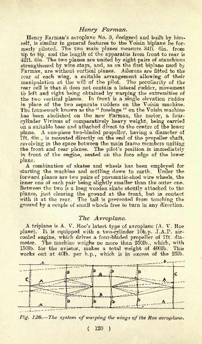
Henry Farman.
Henry Farman's aeroplane No. 3, designed and built by him-
self, is similar in general features to the Voisin biplane he for-
merly piloted. The two main planes measure 34ft Gin. from
tip to tip, and the length of the apparatus from front to rear is
42ft. Gin. The two planes are united by eight pairs of stanchions
strengthened by wire stays, and, as on the first biplane used byFarman, are without vertical planes. Ailerons are fitted to therear of each wing, a suitable arrangement allowing of their
manipulation at the will of the pilot. The peculiarity of therear cell is that it does not contain a lateral rudder, movementto left and right being obtained by warping the extremities of
the two vertical planes. In front is a single elevation rudderin place of the two separate rudders on the Voisin machine.The framework known as the "
fuselage" on the Voisin machine
has been abolished on the new Farman, the motor, a four-
cylinder Vivinus of comparatively heavy weight, being carried
on a suitable base and attached direct to the centre of the lower
plane. A one-piece two-bladed propeller, having a diameter of
7ft. Gin., is mounted directly on the end of the propeller shaft,
revolving in the space between the main frame members unitingthe front and rear planes. The pilot's position is immediatelyin front of the engine, seated on the fore edge of the lower
plane.A combination of skates and wheels has been employed for
starting the machine and settling down to earth. Under theforward planes are two pairs of pneumatic-shod wire wheels, theinner one of each pair being slightly smaller than the outer one.
Between the two is a long wooden skate stoutly attached to the
planes, just clearing the ground at the front, but in contactwith it at the rear. The tail is prevented from touching the
ground by a couple of small wheels free to turn in any direction.
The Avroplane.A triplane is A. V. Roe's latest type of avroplane (A. V. Roe
plane). It is equipped with a two-cylinder lOh.p. J.A.P. air-
cooled engine, which drives a four-bladed propeller of 7ft. dia-
meter. The machine weighs no more than 2501b., which, with1501b. for the aviator, makes a total weight of 4001b. This
works out at 401b. per h.p., which is in excess of the 251b.
Fig. 126. The system of -warping the -wings of the Roe aeroplane.
( 120 )

IT_
!
'
'-^^^^^^^fM
,%p jfig
.Fz. 727. The A. V. Roe aeroplane or "Avroplane."
per h.p. usually carried by the successful French aviators.From tip to tip the main planes measure 20ft., and they are3ft. 7in. deep. The tail is 10ft. wide and of the same depth asthe main planes. The planes are set 3ft. 2in. apart. Theoverall length of the machine is 23ft. The total surface is
320 sq. ft., which works out at just l^lb. per sq. ft.
The machine has several novelties, of which the chief are the
steering gear and the method of bracing and twisting themain planes to control the vertical and lateral course of themachine. The rear vertical rudder is turned by a rotary move-ment of the wheel, the rear planes or tail being fixed firmly tothe body of machine.The tilting and twisting of the main planes is carried out
entirely through levers and rods, without the use of any cordsor pulleys whatsoever, thus removing one source of danger in
an aeroplane.The central main plane (A) (Fig. 126) is braced from end to
end by the wire braces (B), so that a girder unalterable in
shape is secured. Vertical struts (C and D) carry the upperand lower planes and cause them to be warped similarly to themain central plane. To permit this movement (which wouldnot be possible with stiff struts forming part of the girder), thestruts marked D are all thinned in the middle so that they maybend as indicated by the dotted lines. The struts C, of course",do not require to be otherwise than stiff. Connections are madebetween the middle plane at its rear edge, through rods andlevers, to the column of the steering wheel. The rocking upand down of this column moves the main planes and alters the
angle of incidence; turning the steering wheel twists the main
planes and moves the rudder at the same time.Mr. Roe has not yet succeeded in making flights of any
length : we fear that his aeroplane is underpowered.
( 121 )
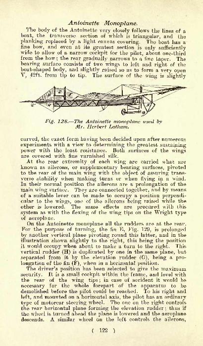
Antoinette Monoplane.The body of the Antoinette very closely follows the lines of a
boat, the transverse section of which is triangular, and theplanking replaced by a light canvas covering. The boat has afine bow, and even at its greatest section is only sufficientlywide to allow of a narrow cockpit for the pilot, about one-thirdfrom the bow
;the rear gradually narrows to a fine taper. The
bearing surface consists of two wings to left and right of the
boat-shaped body, and slightly raised so as to form a very openV, 42ft. from tip to tip. The surface of the wing is slightly
Fig. 128. The Antoinette monoplane used byMr. Herbert Latham.
curved, the exact form having been decided upon after numerousexperiments with a view to determining the greatest sustainingpower with the least resistance. Both surfaces of the wingsare covered with fine varnished silk.
At the rear extremity of each wing are carried what areknown as ailerons, or supplementary bearing surfaces, pivotedto the rear of the main wing with the object of assuring trans-
verse stability when making turns or when flying in a wind.In their normal position the ailerons are a prolongation of themain wing surface. They are connected together, and by meansof a suitable lever can be made to occupy a position perpendi-cular to the wings, one of the ailerons being raised while the
other is lowered. The same effects are procured with this
system as with the flexing of the wing tips on the Wright typeof aeroplane.On the Antoinette monoplane all the rudders are at the rear.
For the purpose of turning, the fin E, Fig. 129, is prolongedby another vertical plane pivoting round this latter, and in theillustration shown slightly to the right, this being the positionit would occupy when about to make a turn to the right. Thisvertical rudder (H) is duplicated by one in the same plane, but
separated from it by the elevation rudder (G), being a pro-
longation of the fin (F), when in a horizontal position.The driver's position has been selected to give the maximum
security. It is a small cockpit within the frame, and level withthe rear of the wing tips; in case of accident it would be
necessary for the whole forepart of the apparatus to bedemolished before the pilot could be reached. To his right and
left, and mounted on a horizontal axis, the pilot has an ordinarytype of motorcar steering wheel. The one on the right controls
the rear horizontal plane forming the elevation rudder;thus if
the wheel is turned ahead the plane is lowered and the aeroplanedescends. A similar wheel on the left controls the ailerons,
( 122 )
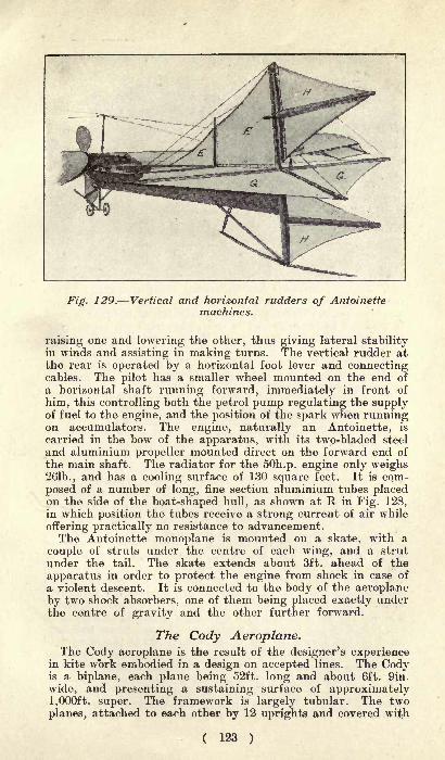
Fig. 129. Vertical and horizontal rudders of Antoinettemachines.
raising one and lowering the other, thus giving lateral stabilityin winds and assisting in making turns. The vertical rudder at
the rear is operated by a horizontal foot lever and connectingcables. The pilot has a smaller wheel mounted on the end of
a horizontal shaft running forward, immediately in front of
him, this controlling both the petrol pump regulating the supplyof fuel to the engine, and the position of the spark when runningon accumulators. The engine, naturally an Antoinette, is
carried in the bow of the apparatus, with its two-bladed steel
and aluminium propeller mounted direct on the forward end of
the main shaft. The radiator for the SOh.p. engine only weighs261b., and has a cooling surface of 130 square feet. It is com-
posed of a number of long, fine section aluminium tubes placedon the side of the boat-shaped hull, as shown at R in Fig. 128,in which position the tubes receive a strong current of air while
offering practically no resistance to advancement.The Antoinette monoplane is mounted on a skate, with a
couple of struts under the centre of each wing, and a strut
under the tail. The skate extends about 3ft. ahead of the
apparatus in order to protect the engine from shock in case of
a violent descent. It is connected to the body of the aeroplaneby two shock absorbers, one of them being placed exactly underthe centre of gravity and the other further forward.
The Cody Aeroplane.The Cody aeroplane is the result of the designer's experience
in kite work embodied in a design on accepted lines. The Codyis a biplane, each plane being 52ft. long and about 6ft. 9in.
wide, and presenting a sustaining surface of approximately1,000ft. super. The framework is largely tubular. The two
planes, attached to each other by 12 uprights and covered with
( 123 )

Fig. 130. The Cody aeroplane on La/fan's Plain, 1909.
rubber-proofed canvas, are quite flat. Since it was first broughtout, the Cody machine has undergone many changes. At thetime of writing it has just undergone some further alterations,and now has the righting planes (horizontal) at the rear insteadof in front as formerly, while it also has righting planes (ver-
tical) at each end of the plane. Rudders are placed both fore
and aft. The power is provided by an eight-cylinder water-cooled Antoinette engine of 50h.p. The radiator is composedof copper tubes. A new engine of SOh.p. is to be installed
as soon as possible.
Howard Wright Aeroplane.Both monoplanes and biplanes have come from Mr. Howard
Wright, but it is with the two-decker that experience has been
gained by this designer. On his restricted flying ground at
Fambridge the machine has frequently left the ground in the
small area available. Two unique features distinguish the
design : the tubular steel framing and the twin propellers re-
volving in opposite directions on the same shaft. The mainsurfaces of the machine present a lifting area of 520 sq. ft.,
the tail offering another 100 sq. ft. With a 50h.p. four-cylin-der Metallurgique motor, running at l,500r.p.m., the soaring
speed is 25m.p.h. and the flying speed 36m.p.h. A peculiar
gearing, which baffles description and at first deceives even the
eye of the trained engineer, provides the three-to-one speedreduction to the propellers and the reverse motion to one of
them. Only three gearwheels are necessary, although a fourth
is added for balance, and by a seemingly paradoxical movementtwo-thirds of the torque is transmitted to one screw and one-
third of the torque to the other screw. With the same dia-
meter for both propellers, the double thrust on one is obtained
by the use of four blades, each of the same area as either of
the two blades of the second propeller. Elevation is obtained
by means of a horizontal rudder in front. Lateral stability is
governed by the " ailerons" attached to the four after corners
of the main planes, the four " ailerons"
being simultaneously
( 124 )

Fig. 131. Mr. Howard T. Wright's aeroplane:Mr. Malcolm Ker-Seymer, pilot.
controlled by a single movement on the part of the aviator.
They have this distinction from other "ailerons
" that theyhave as much upward as downward movement. The machineruns over the ground on two wheels only, one under the aviator,the other under the tail. Two grounding wheels are fitted
under the extremities of the lower main plane to preserve the
wings from damage. An advantage of this bicycle mountingis that the budding aviator learns to obtain lateral balancebefore leaving the ground, and is thus at an advantage whenhe first rises in the air.
The Bleriot Monoplane."
Bleriot XII.," the most recent of Louis Bleriot's series of
monoplane flying machines, appears to be the most successful
of them all, for it has proved capable of carrying two passen-gers with ease. The wings, which appear to measure 42ft.
from tip to tip and to be about 6^ft. from front to rear thebuilder wishes to withhold the exact dimensions at presenthave a considerable curve from front to rear, have their angleswidely rounded off, and are covered on both upper and lowerfaces with fine canvas. Below the main wings are two smallhorizontal planes attached to the lower frame members. Atthe rear are two horizontal planes, an upper one, fixed, butmounted on hinges so that the angle of inclination can bevaried as found necessary, and a lower one a little further to
rear, pivotable at the will of the pilot to form elevation rudder.Above the framework, and about one-quarter from the rear, is
a large lateral rudder, being a square with the angles roundedoff. An addition made to the machine takes the form of a jib-
shaped fin placed ahead of the lateral rudder, this having beenfound necessary to increase the lateral stability of the aeroplane.
( 125 )

The engine is an eight-cylinder E.N.V. mounted on a lightsteel chassis and attached to the lower frame members imme-diately in front of the apparatus. It drives a very large dia-
meter all-wood propeller, built by Chauviere, by means of a
pinion on the engine shaft and single chain to the propellershaft, the speed of the propeller being reduced to about 600revolutions a minute. The pilot's seat is set across the lowerframe members, behind the engine and under the wings. Inthis position M. Bleriot declares that he is better protectedthan in any other, for in case of a fall it is the motor whichreceives the shock, and not the pilot ;
while being placed nearthe ground, he is able to make his descents with greater cer-
tainty than when mounted higher. The seat is of sufficient
width to accommodate two persons, but it has been found thata passenger by the side of the pilot alters the centre of gravity,better results being obtainable with the passenger sitting onthe fram a little ahead of the pilot and facing him.
t,., . . >*"' -
" Silver Dart."11
Silver Dart " was the fourth flying machine made by theAerial Experimental Association. She was built at a quietlittle watering place called Baddeck, on Bras d'Or Lakes, N.S.She is a biplane, the planes being bowed so that the ends con-
verge towards one another. They are also arched, and are
placed with the concave sides facing each other. Each planeis 6ft. wide and covered with vulcanised silk. The planes are
rigid, with the exception of small triangular wings at theextreme tips. At the rear is the rudder. The elevation is
controlled by a horizontal rudder (two planes) fixed in front.
The power is obtained from an eight-cylinder air-cooled Curtis
engine (V type) developing 50h.p. This drives a ten-bladedwooden propeller by means of four V leather belts.
With "Silver Dart "
J. A. D. McCurdy has equalled thefeats of Farman and Bleriot in flying across country. His best
record in this respect is 20 miles. On that occasion the course
lay over ice, across the town of Baddeck, over woods, etc.
McCurdy, after this flight, stated that he saw no reason whyten times the distance should not be accomplished soon. It was
only a matter of getting every detail perfect. He also stated
that the question of lifting weight was a problem they hadsolved. What they wanted now was a propeller that would
give greater forward thrust.
Short Brothers.
Besides the dozen machines which they are building in this
country under the Wright Bros.' patents, Messrs. Short Bros.,of Battersea, London, and of Sheppey, Kent,, are devotingattention to aeroplanes of their own design. At the Aero Showof 1909 the main framing of one of these machines was ex-
hibited, but during the intervening period many alterations
have been made in the details. Messrs. Short Bros, are pur-
suing a policy of reticence, and up to the time when this bookhas gone to press have asked us not to make public any infor-
mation about their aeroplanes.
( 126 )
AEROPLANE SPARS, RIGGING,AND FITTINGS.
The structure of an aeroplane consists of three principal
portions, in addition to the propelling machinery, and these
three may be termed (1) the struts or members of the frameworkwhich are under compression, torsion, or cross strain
; (2) thetension rods or wires
;and (3) the material of which plane sur-
faces are made. In the case of the first two portions of the
structure, aeroplane constructors might do worse than turn to
the builders and designers of light racing sailing boats and
canoes, as, in these little craft, piano-wire stays and hollow
spars have been brought to a high state of perfection for some
years. Probably, every possible variety of spar has been tried
in these vessels at some time or other, from the original solid
stick to the modern hollow spar, which has superseded everythingelse, next in value being the bamboo. Of all these kinds,the one now in use consists of a piece of perfectly clean-grainedCalifornian or Nova Scotian spruce, cut in half lengthways, and,after the centre has been scooped out, glued together again.These spars are only about 30 per cent, of the weight of a solid
spar of the same size and material, yet they have about 75 percent, of the strength of the solid wood, thus showing a greatadvantage, Avhich more than counterbalances their high price.After the two halves are glued together they are screwed
up between two planks by means of a series of cramps, as,unless the glue is under great pressure, a good joint cannotbe obtained. The two principal makers of hollow sparsin this country are Messrs. G. Hollwey and Sr>ns, of
Dublin (who were the first firm in Great Britain to take up themanufacture of hollow spars), and Messrs. A. Burgoine, of
Kingston-on-Thames, who have made several hollow frames forthe Clarke aeroplane. Many people think that a bamboo is as
light and strong as a hollow spar of the same size, but thisis by no means the case, as a series of tests carried out byus some years ago proved the hollow spar to be 15 per cent,
lighter and nearly 20 per cent, stiffer than a bamboo of thesame length and diameter. In the larger spars the differencein favour of the hollow spar is even more marked, as theshell can be kept thinner in proportion to the outer diameter.Steel tubes have often been tried in place of wooden spars,but they are not so good, being heavier for a given strength,and, moreover, they are prone to buckle and dent.
Wire Stays.
Quite as important as the wood frame is the wire used forthe stays and the method of attaching it to the frame, as
lightness and neatness are essential on the aeroplane. It is
of no use to fasten off the ends of the wire in such a manner that
( 124 )
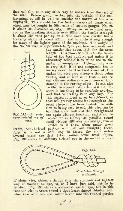
they will slip, or in any othei- way be weaker than the rest ofthe wire. Before going further into the details of the endfastenings it will be well to consider the nature of the wire
employed. This should be the best silver-plated piano wire,which may be bought in 50ft. coils of various gauges; No. 26is about .06 diameter or, say, .002 sq. in. in sectional area,and as the breaking strain is over SOOlb., the tensile strengthis about 125 tons per.sq. in.! The next size smaller has a
breaking strain of about 5201b., and is quite strong enoughfor many of the lighter parts of the machine. The weight of
the No. 26 wire is approximately 2lb. per hundred yards andthe smaller size about Iflb. for the same
length. This piano wire is not easy to ob-
tain of the best quality, and unless it is
absolutely reliable it is of no use to themaker of aeroplanes. Although the wireis very stiff, it is not tempered, but is
merely drawn hard and not annealed;this
makes the wire very strong without beingbrittle, and so soft is it that it can becut with any ordinary wire cutters without
damage to the cutting edges. It can also
be filed to a point with a fine saw file, butthere is one thing to be carefully avoided,and that is heating it in any way. Forthis reason it must never be soldered, as
that will greatly reduce its strength at the
point where it has been heated. In addi-
tion to being easy to cut, this wire can be
bent flat upon itself and then straightenedout again without breaking, and it can beFig. 132. An ordi
nary twisted eye of twisted up as tightly as possible roundwire - itself without difficulty or damage ;
but so
flexible is it that, when under great
strain, the twisted portion will pull out straight; there-
fore, it is not a safe way to fasten the ends unless
several turns are first taken round some fixed object.
Fig. 132 shows an ordinary twisted eye in the end of a piece
Fig. 133.
Wire taken througha thimble.
of piano wire, which, although it is the simplest and lightest
way of making an eye, is, as I have just said, not to be
trusted. Fig. 133 shows a somewhat similar eye, but in this
case the wire is taken round a light heart-shaped thimble, and,
when twisted at the end, solder is run into the twisted portion
128 )

and round the thimble with a blow pipe. This will prevent anypossibility of the wire slipping, but it will also reduce the
strength at that point, so neither of these two methods is
to be considered satisfactory. Figs. 134-138 show a simple formof shoe which we have devised for this wire, and which we havefound quite satisfactory after two years hard testing. The
drawings show a front and back view, a section through thecentre of its length and plans of the top and bottom. It will
-A
Fig. 134.Rear view.
Fig. 135.Front view.
Fig. 137.
View fromtop.
Fig. 136.Sectional view
Fig. 138.
View frombottom.
The Hope Rigging Eye.
be seen that the shoe consists of a small stamping of steel or
gunmetal with a flattened conical end through which the wire
passes. This end has two holes of the same size as the wire,drilled at a small angle, so that, while they start side by side
underneath (Fig. 138), they both come out of one hole at the
top (Fig. 137). Another method in the smallest shoes when theyare made of gunmetal is to drill a central hole and drift it
out at the bottom to twice its width or a little more. Thelower part of the shoe may have an eye as shown in the fore-
going figures or it may be one of the ends of a rigging screwas in Fig. 139. In all cases the method of attaching it to thewire is the same, and can easily be understood from the illustra-
tions. In these figures A is the wire, B the shoe with an eye (E)at the lower end, D is the tapered hole in the upper part of the
shoe, and C is the end of the wire (A) bent round upon itself
and driven up into the tapered hole in the shoe. The method
129 )

of fitting the shoe on the end of the wire is as follows : Thewire is passed down through the shoe from the small end or
top. It is then bent slowly over until the end is turned backupon the main piece at a sharp angle, but, before it is bent far
enough to touch it, the point is filed off on the inside to a longbevel, so that, when the two parts are closed together with thepliers, they form a reverse taper, which fits closely into the
tapered hole in the shoe as in D (Fig. 135). If the wire is care-
fully filed and bent, it should jam tightly in the shoe, and thestrain on the wire will then close it up tighter and cause it to
grip the inside of the shoe and itself. It should be noted, how-ever, that, although the wire is very
" kind "in bending, yet
it is fairly hard steel, and if bent too suddenly may break in the
nip. One great advantage of this form of shoe is that it canbe removed with the loss of only |in. of wire, as if it is cutat the point where it is doubled over only the short piece is
wasted.The best method of tightening the wires is by the
use of the rigging screw (Fig. 139) or"turnbuckle," as
Fig. 139. A turnbuckle or rigging screw.
it is called in America. It consists of a right and left-
handed bow nut, the centre of which is cut away anda pair of screws, one with a right-handed thread and theother with a left-handed thread, fitting the two ends of thenut as shown in the figure. One of these screws has on its outerend a shoe exactly the same in design as that already describedand illustrated in Figs. 134-138, while the other end is fitted
either with an eye as shown or with a pair of shackle lugs as
Fig. 140. A simple rigging screw made out of a short
cycle spoke and nipple, and two strips of metal.
may be most convenient. With a screw of this description anydegree of strain can be put on the wire, but great care mustbe taken in selecting the screws, as unless they are of the verybest quality, they are very apt to break at the end of thethread. For this reason it is always safest to have the screws
nearly twice the diameter of the piano wire, and the threadsshould be carefully examined, while the nuts should be as longas possible. Screws of a size suitable for the fine wire requiredcan now be bought ready made, and, no doubt, as the demandfor aeroplanes increases, both shoes and rigging screws will
soon be obtainable as a stock article.
( 130 )

COVERING MATERIALS FORAEROPLANES.
Of the various kinds of materials used for covering the aero-
planes of flying machines, fine quality canvas, treated or un-
treated, is generally used. Several firms supply it covered onone or both sides with a very fine coat of indiarubber. Thematerial thus treated will weigh anything between four to
nine ounces per square yard. The joints are solutioned and
sewn, making a waterproof joint. It is rather expensive, cost-
ing from 4s. to 7s. a square yard.M. Santos Dumont is using oiled Japanese silk on his latest
aeroplanes. This is naturally costly, but it is very light.Fine canvas covered with pegamoid is likely to become popu-
lar with some aeroplane builders. It has a smooth surface andis about the same weight as rubber-treated material, but con-
siderably less in price, costing from Is. 6d. to 3s. a square yard.Unless canvas is treated with some damp-proof solution it
will be found to alter considerably with the weather. Ordinaryuntreated aeroplane canvas will slacken to a very noticeable
extent during wet weather. A cheap damp-proofing for canvasis boiled oil, which can be applied by an amateur with a large-size paint brush. This, of course, does not make such a nice
smooth surface as rubber or pegamoid.The- most difficult part to which covering material has to be
attached is the underside or concave part of ribs. The materialis usually sewn on, but a simple way is to use special big-headednails and grips, which are being made specially for this purpose.Some experimenters use paper backed with muslin, arid then
varnish the planes after they are made up. This method lendsitself to easy repairing. M. Bleriot has used a strong paperparchment for some of his machines. A. V. Roe has recentlybeen using a cotton oil paper covered with muslin, weighingonly two ounces per square yard. This can be boughtprepared, and is applied damp and glued on. When dry it hasa smooth, drum-like surface. If experiments are likely to becarried out in rainy weather, the joints or, indeed, the wholesurface should be covered with a thin coat of oak varnish or
boiled oil. It is naturally not so strong as canvas, but can be
easily repaired with the aid of the glue pot, and is a suitable
and very cheap covering material for beginners.Aluminium cloth woven with very fine threads of aluminium
wire has recently been discussed, but very thin aluminium sheetswould be no heavier, and would have a very smooth surface.
Another material of rather different construction is manufac-tured by Hutchinson, the French tyre maker. It is made of
finest-grade Egyptian cotton, the outer diagonal being dyedyellow with chromate of lead to protect the rubber proofingfrom the sun's rays.The material used by Farman, Voisin, Wright (in one in-
stance), and others is made by the Continental Tyre Co.
( 131 ) i2
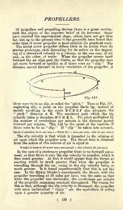
PROPELLERS.
Of propellers and propelling devices there is a great variety,each the object of the supreme belief of its inventor. Somehave reached the experimental stage, others have not got thus
far, but up to the present time it has generally been found that
some type of screw propeller is most suitable for practical work.The aerial screw propeller differs little in its action from its
marine prototype, each depending for its action on the impart-
ing of a sternward velocity to a column, in the one case, of air
and, in the other, of water. When the propeller screws itself
forward the air slips past the blades, so that the propeller does
not move forward so quickly as if there were no "slip." The
distance moved forward at every revolution of the propeller, if
Fig. 141.
there were to be no slip, is called the "pitch." Thus in Fig. 141,
neglecting slip, a point on the propeller blade tip, instead of
merely revolving in the circle B C D E F also advances the"pitch
"distance A B. The resultant path which the tip
actually takes is therefore B G H K L. The pitch multiplied bythe number of revolutions per minute is the distance movedforward per minute. This will be the speed of the machine if
there were to be no "slip." If
"slip
" be taken into account,
Speed of machine (in ft. per min.) == Pitch (ft.) x revs, per min. slip (ft. per min.).
The slip velocity is that which is imparted to the column of
air upon which the propeller acts. The thrust that is obtainedfrom the action of this column of air is equal to
Weight of mass of air acted upon per second x slip velocity (ft. per sec.).
In the case of a stationary propeller there is no forward move-
ment, so that there is only the slip velocity to consider, which is
then much greater. At first it would appear that the thrust at
starting would be much greater than when the propeller is
travelling through the air, owing to the slip velocity being so
much greater. It is found experimentally that this is not thecase. In Sir Hiram Maxim's experiments, the thrust, with the
propeller travelling at 40 miles per hour, was the same as thatwhen the propeller was stationary, the revolutions per minuteof the propeller remaining constant throughout. The reason for
this is that, although the slip velocity is decreased, the propelleracts upon undisturbed "
virgin"
air, the equivalent of actingupon a greater quantity of air.
( 132 )
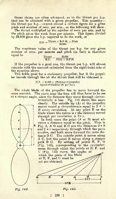
Great claims are often advanced, as to the thrust per h.p.that can be obtained with a given propeller. This quantitythe thrust per h.p. cannot exceed a certain figure for a givenpitch and number of revs, per min., as the following will show :
The thrust multiplied by the number of revs, per min. and bythe pitch gives the work done per minute. This figure divided
by 33,000 gives the h.p. required to do the work, or
Thrust X R.P.M. x PitchH.P.=337060".
The maximum value of the thrust per h.p. for any givennumber of revs, per minute and pitch (in feet) is therefore6(lUalt0 Thrust _ 33.000
H.P. Pitch x R.P.M.
If the propeller is a good one, the thrust per h.p. will almostcoincide with the amount calculated from the right-hand side of
the equation above.This holds good for a stationary propeller, but if the propel-
ler travels through the air the thrust that will be obtained is
H.P. x 33,000 x efficiency of propeller
Speed of machine (ft. per sec.).
The whole blade of the propeller has to move forward thesame amount. The parts near the boss will thus have to be setat a steeper angle, since the distance they move through circum-
ferentially is less. Fig. 142 shows this more
clearly. The outside tip (A) of the propellermoves round a circumference equal to 2 if XR every revolution. At any point B on the
blade where the radius is r the distance moved
through per revolution is 2 r.
In both cases the point (A or B) must ad-
vance a distance equal to the pitch. Thus in
Fig. 3, A O and B O are the distances 2 -* Rand 2 TT r respectively through which the parts
revolve, and both move forward the same dis-
tance O C. The outside point A moves alongA C, but the point B moves along a steeper
path B C. By setting off points E, F, G(Fig. 143), corresponding to the circumfer-
ences through which the points at E, F, andG (Fig. 142) move, the angles at ^which the parts of the bladeat E, F, and G must beset are obtained.
Fig, 142. Fig. 143.
( 133 )

To determine with accuracy the thrust that a propeller will
give and the h.p. that it will absorb requires a great amount of
experimental work. Maxim tested his screws when stationaryby mounting them on a shaft driven by belt from a steam
engine. The shaft was free to move in its bearings and to oneend of the shaft was fixed a spring balance, measuring the
Fig. 144. Capt. Ferber's road carriage for testingthe values of propellers.
thrust due to the propeller when revolved. To test them when
moving through the air, the screws were mounted at the end of
a long arm, and the latter was rotated. By various ingeniousmeans he measured the thrust when moving at a given speedthrough the air and at a given number of revolutions.
Captain Ferber carried out a series of tests on propellers bymaking them drive a small chassis. This arrangement ran alongthe road under its own power, and various measurements of
thrust and power were made.For heliocopteres, where vertical screws are used, the pitch
is made small and the diameter large. There is then a largecolumn of air acted upon and a low velocity imparted to it.
From a consideration of the equations given above it will beseen that this ensures a large thrust per h.p.
( 134 )

AERIAL MOTORS.
From the earliest stages of the flying movement it has been
recognised that a power-producing plant of lower weight perhorse-powe'r than anything employed for land or marine travelmust be procured for successful navigation of the air. Longbefore the petrol engine was sufficiently developed to be of
service, special light-weight steam engines were constructedfor early flying machines, two important examples of their use
being on the Langley model aeroplane, probably the first power-driven, heavier-than-air machine to leave -the ground, and onthe Ader and the Maxim, the first man-carrying aeroplanes to
accomplish flight.But the petrol engine offered distinct advantages over the
steam engine for use on aeroplanes, and, during the active
period from 1904 to the present day, has been used almost
exclusively. French engineers, in particular, recognised that,for flying to be successfully developed, the petrol engine, as
used on motorcars, must be made lighter and, generally, morereliable. Thus, in France, experimental work in light-weightpetrol engines has been carried on concurrently with researchesin the best form of sustaining surfaces and methods of securingequilibrium, until, at present, there are at least a dozen suc-
cessful aeroplane engines, all of the internal-combustion four-
cycle type, but differing considerably from their predecessorsbuilt for use on motorcars. Now, certain aeronauts maintainthat the search for feather-weight engines is labour lost, andthat flights can be made with any well-constructed car engine.Facts, however, are against this theory, for all flights, up to
the present, have been accomplished by special engines, even the
Wright motor, the one which most closely approximates to thecar type of engine, being specially lightened and distinctive in
Low weight per horse-power is undoubtedly not only desir-
able, but essential for driving an aeroplane. Smoothness of
running, reliability and regularity are equally important, andit remains to be seen whether the newer light-weight engines,with six, seven, eight or fourteen cylinders, can be made as
satisfactory in this respect as the standard but heavier type of
engine with only four cylinders.
The Wolseley Engine.The Wolseley Co. has taken up the construction of light
engines for aerial work. The firm has reduced the weight of
its new type to 81b. per horse-power, this figure being in-
clusive of flywheel, ignition, water-pipes, gas-pipes, etc., every-
thing necessary to the running of the motor being weighed.
Although there are many lighter engines, the Wolseley Co. has
( 135 )
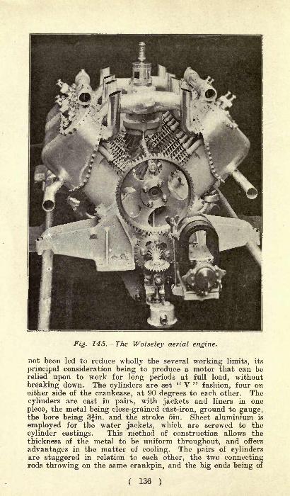
Fig. 145. The Wolseley aerial engine.
not been led to reduce wholly the several working limits, its
principal consideration being to produce a motor that can berelied upon to work for long periods at full load, without
breaking down. The cylinders are set" V "
fashion, four oneither side of the crankcase, at 90 degrees to each other. Thecylinders are cast in pairs, with jackets and liners in one
piece, the metal being close-grained cast-iron, ground to gauge,the bore being 3fin. and the stroke 5in. Sheet aluminium is
employed for the water jackets, which are screwed to the
cylinder castings. This method of construction allows thethickness of the metal to be uniform throughout, and offers
advantages in the matter of cooling. The pairs of cylindersare staggered in relation to each other, the two connectingrods throwing on the same crankpin, and the big ends being of
( 136 )

Fig. 146. The Wolseley aerial engine seen from above.
phosphor-bronze, white metal lined. Three large bearings are
provided for the crankshaft, and the lubrication is effectedunder pressure to all the main bearings and connecting rods.All the valves are side by side facing the centre, and are
operated by a central camshaft, lifting shoes being interposedbetween the cams and tappets. The exhaust and induction
piping is therefore situated between the cylinders over the topof the crankcase, the carburetter being mounted in the centre.
Thermo-syphon cooling has been adopted. For the ignition,there is one eight-cylinder high-tension magneto running atcrankshaft spaed, a separate distributor being fitted and drivenoff the camshaft. One of the many good features of this en-
gine is that the position of the carburetter enables a symmetri-cal induction system to be obtained, the distribution of gas tothe cylinders being uniform.
The Gobron Engine.Within each cylinder of the Gobron engine are two pistons, the
upper one having its head turned downwards and connected upto an overhead beam, which in turn is connected to the main-shaft of the engine. Instead of the explosion taking place be-
tween the piston and the cylinder head, it occurs between theheads of the two pistons, which come together on the com-pression and exhaust strokes and leave one another, one ascend-
ing and the other descending, on the intake and power strokes.The principle will be understood by a reference to Fig. 147.
On the aeronautical engine there are eight cylinders, and con-
sequently 16 pistons. Instead of being mounted vertically onthe crankcase, as in the car engine, the cylinders form an X.
( 137 )
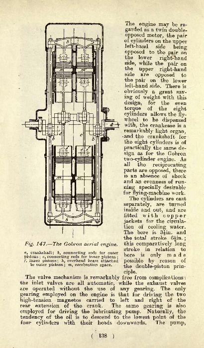
The engine may be re-
garded as a twin double-
opposed motor, the pairof cylinders on the upperleft-hand side beingopposed to the pair onthe lower right-handside, while the pair onthe upper right-handside are opposed tothe pair on the lowerleft-hand side. There is
obviously a great sav-
ing of weight with this
design, for the even
torque of the eightcylinders allows the fly-wheel to be dispensedwith, the crankcase is a
remarkably light organ,and the crankshaft forthe eight cylinders is of
practically the same de-
sign as for the Gobrontwo-cylinder engine. Asall the reciprocatingparts are opposed, thereis an absence of shockand an evenness of run-
ning specially desirablefor flying-machine work.The cylinders are cast
separately, are turnedinside and out, and arefitted with copperjackets for the circula-
tion of cooling water.The bore is 3^in. andthe total stroke 6^in. ;
this comparatively longstroke in relation to
bore is only madepossible by reason of
the double-piston prin-
ciple.The valve mechanism is remarkably free from complications :
the inlet valves are all automatic, while the exhaust valvesare operated without the use of any gearing. The onlygearing employed on the engine is that for driving the two
high-tension magnetos carried to left and right of therear extension of the crank. The same gearing is also
employed for driving the lubricating pump. Naturally, the
tendency of the oil is to descend to the lowest point of thefour cylinders with their heads downwards. The pump,
Fig. 147. The Gobron aerial engine.
a, crankshaft; b, connecting rods for outerpistons ; c, connecting rods for inner pistons ;
f, inner pistons; 7^ overhead beam attachedto outer pistons ; ra, combustion space.
( 138 )
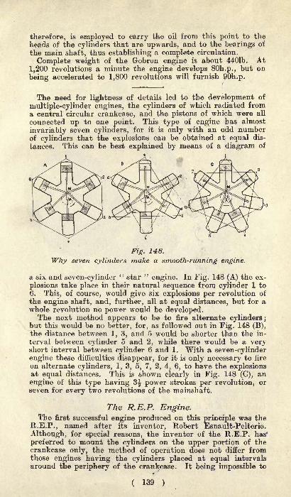
therefore, is employed to carry the oil from this point to the
heads of the cylinders that are upwards, and to the bearings of
the main shaft, thus establishing a complete circulation.
Complete weight of the Gobron engine is about 4401b. At
1,200 revolutions a minute the engine develops SOh.p., but on
being accelerated to 1,800 revolutions will furnish 90h.p.
The need for lightness of details led to the development of
multiple-cylinder engines, the cylinders of which radiated froma central circular crankcase, and the pistons of which were all
connected up to one point. This type of engine has almost
invariably seven cylinders, for it is only with an odd numberof cylinders that the explosions can be obtained at equal dis-
tances. This can be best explained by means of a diagram of
Fig. 148.
Why seven cylinders make a smooth-running engine.
a six and seven-cylinder" star
"engine. In Fig. 148 (A) the ex-
plosions take place in their natural sequence from cylinder 1 to
6. This, of course, would give six explosions per revolution of
the engine shaft, and, further, all at equal distances, but for awhole revolution no power would be developed.The next method appears to be to fire alternate cylinders ;
but this would be no better, for, as followed out in Fig. 148 (B),the distance between 1, 3, and 5 would be shorter than the in-
terval between cylinder 5 and 2, while there would be a veryshort interval between cylinder 6 and 1. With a seven-cylinderengine these difficulties disappear, for it is only necessary to fire
on alternate cylinders, 1, 3, 5, 7, 2, 4, 6, to have the explosionsat equal distances. This is shown clearly in Fig. 148 (C), an
engine of this type having 3^ power strokes per revolution, orseven for every two revolutions of the mainshaft.
The R.E.P. Engine.The first successful engine produced on this principle was the
R.E.P., named after its inventor, Robert Esnault-Pelterie.
Although, for special reasons, the inventor of the R.E.P. has*
preferred to mount the cylinders on the upper portion of thecrankcase only, the method of operation does not differ fromthose engines having the cylinders placed at equal intervals
around the periphery of the crankcase. It being impossible to
( 139 )

get such a large number of cylinders on the upper half of acircular base of moderate dimensions, the designer has slightly
staggered them, four being in one plane and the three others
slightly in the rear and in another plane. For such an engine,the crankshaft
Fig. 149.-J^fcv must have two
The main JelM arms, or throws,connecting fa to Qne of whic}]
the connectingrods of four
pistons will be
Fig. 150. The piston and gudgeonpin bearing.
attached, and to the other will be linked up the three remain-
ing pistons. As is shown in Fig. 149, there is one main connect-
ing rod receiving three separate rods, two being on one side
and one on another.The circular crankcase is an aluminium casting to which the
cast-iron cylinders are each secured by three bolts, nuts, andlock-nuts. Very light steel pistons are employed, the walls
being so thin that it would be impossible to attach the gudgeonpin in the usual manner by bearings in the wall of the piston.The central portion of the head of the piston is, therefore,threaded to receive a special bearing. This piece, shown in
Fig. 150, is screwed into the head of the piston, being preventedfrom turning by means of a countersunk screw, and carries,
integral with it, the two bearings for the gudgeon pin.On the R.E.P. engine there is but one valve for both the
intake of the fresh charge and for the exhaust of the gases.It is carried in the head, and is operated in a special manner
by an overhead rocker arm. The manner in which the twofunctions are fulfilled by one organ is both simple and effective.
The rocker arm, operated by the camshaft, can maintain thevalve in three distinct positions. On the full opening, the
valve is lifted off its seat in the usual manner, allowing the

aspiration of explosive mixture. In another position, a steel
collar surrounding the valve stem uncovers a number of holeswithin a cylindrical cage, thus giving communication betweenthe exhaust pipes and the combustion chamber and allowingthe spent gases to be driven out. In its third position, theseholes are closed and the valve face is resting on its seating,thus shutting all connection with both inlet and exhaust pipes.The valves are operated by a single cam, or, more correctly,
by a single disc, the face of which has three pairs of bosses,the three larger ones corresponding to the lift of the valve for in-
take and the three smaller ones to the lift for the exhaust.
The seven-cylinder R.E.P. engine has a bore of 3.Sin. and a
stroke of 3.5in. It is rated at 30h.p. at 1,500 revolutions a
minute, and weighs complete, ready for running, 1151b.
The Gnome Engine.
The seven cylinders of the Gnome aeronautical engine radiate
from a circular crankcase. Unlike the standard type of engine,on which the cylinders are stationary and the crankshaft is
driven round by reason of the power strokes on the piston, the
Gnome engine has a fixed crankshaft, with cylinders and crank-
case revolving round it. With such a type of engine, air-cooling
Fig. 151. The seven-cylindered Gnome engine.
( 141 )
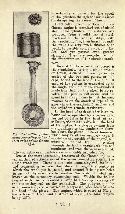
is naturally employed, for the speedof the cylinders through the air is amplefor dissipating the excess of heat.
Practically every portion of theGnome engine is machined out of nickel
steel. The cylinders, for instance, are
produced from a solid bar of steel,machined to the required shape, withtheir radiating fins, then bored out until
the walls are very much thinner thanwould be possible with a cast-iron cylin-
der, and yet possess even greater
strength. They are mounted aroundthe circumference of the circular crank-
case.
The axis of the wheel thus formed is
the crankshaft, having a single crank,or throw, secured in bearings in thecentre of the two end plates, or hubcaps, bolted to the face of the hub. If
each of the pistons is connected up tothe single crank pin of the crankshaft it
is obvious that, on the wheel being re-
volved, the pistons will ascend and de-
scend in their cylinders in just the samemanner as on the standard type of en-
gine where the crankshaft revolves andthe cylinders remain stationary.
In the head of each cylinder is an ex-haust valve, operated by a rocker arm.Instead of being in the head of the
cylinder, the intake valve is in the headof the piston, the charge passing fromthe crankcase to the combustion cham-
,_ ,_, ber above the piston. The carburetter,Fig. 152. I he piston, which may be of any ordinary type, ismain connecting rod, and carried on the outside of the -^ ^inlet valve of the Gnome mixture obtained from it passing
through the hollow crankshaft into thecrankcase, and from there, as explained,
into the cylinders. Lubrication is suitably provided for.
One of the most interesting features of the Gnome engine is
the method of attachment of the seven connecting rods to the
single crank pin. There is one main connecting rod, its lowerend terminating in two steel discs, through the centre of
which the crank pin is passed, and around it being six holes
in each of the two discs to receive the ends of what areknown as the secondary connecting rods. Within the hollowface of each disc is mounted a large ball bearing carrying all
the connecting rods on the crankshaft. The gudgeon pin for
each connecting rod is carried in a separate piece screwed into
the head of the piston. The engine, which is rated at 50h.p.,has a bore of 4.Sin. and a stroke of 4.7in., the total weightbeing 1651b.
( 142 )

Bayard-Clement.
In principle there is a similarity between the Gnome air-
cooled rotary engine and the seven-cylinder water-cooled engineproduced at the Bayard-Clement factory. This latter has seven
cylinders radiating from a circular crankcase, the axes of the
cylinders being placed horizontally, with the axis of the crank-shaft vertical. Here the cylinders are fixed, the explosions
Fig. 153. One of the cylinders and the valve gear of a
Bayard-Clement engine.
driving round the crankshaft, as on the standard type of engine.Water cooling is employed, the water circulating through a
copper jacket surrounding the cylinder walls. The cylinders,which are of steel, are bolted to their seating in the usual way,and have a bore of 3.9in. and a stroke of 4.4in., the powerdeveloped being 50h.p. Each cylinder has a separate dome-shaped head screwed into position and then brazed
;the combus-
tion chamber is hemispherical, this form giving the greatestefficiency, there being no pockets into which the gas can becomelodged, and but small loss from radiation. There are separateintake and exhaust valves in the head of the cylinder, the twobeing operated by a single rocker arm with blade springs, with,of course, but one horizontal tappet rod. One position of thebeam opens the inlet valve, while the opposite position operatesthe exhaust.
In the upper portion of the crankcase are housed the valve-
operating mechanism and all the timing gear. It is within this
casing that is lodged the central cam, receiving its movementfrom an intermediate gear and turning eight times slower thanthe main shaft. The single cam carries four bosses and four
hollows, corresponding to the position of the rocker arm for theexhaust and the inlet. Explosions take place in alternate cylin-ders at each revolution, there being consequently 3^ explosionsper revolution of the engine, or seven explosions for two revolu-tions. The commutator is mounted on a vertical spindle anddriven off the main shaft at half the speed of this latter. Thecarburetter is carried at the base of the engine, outside thecrank chamber, but feeding its mixture into a receiver within
( 143 )

the case, from which the intake pipes lead to the different
cylinders. The carburetter weighs lib.
The vertical crankshaft, in two parts bolted together andcarried on ball bearings, has a single crank pin to which all theseven connecting rods are attached. There are no flywheels,either internally or externally.The axis of the main shaft being vertical, it is necessary, for
aeroplane work, to drive through bevel gearing to the horizontal
propeller shaft. This movement is obtained by a pinion on the
extremity of the mainshaft meshing with a vertical crown gear-wheel on the propeller shaft, the latter being geared down in
the proportion 1 to 5.
Pipe.A very light engine has been produced by the Pipe Co. This
engine, which develops 50h.p. at l,200r.p.m., and a maximumof 70h.p. at l,950r.p.m., has eight cylinders of 100mm. bore by100mm. stroke. The cylinders are mounted " V " fashion and
Fig. 154. The eight-cylinder Pipe engine elevation.
staggered in the usual manner of the aero engines; but fromthis point the design is quite a departure. Over the trunks of
each pair of cylinders there is a light metal hood, a single longhood extending over the combustion head and valve chamberson each side of the crankcase. These hoods form jackets
through which not water but air is circulated by a blower
mounted on one end of the crankshaft. The exhaust and inlet
valves are united in one detachable piece set concentrically in
the hemispherical combustion dome. They are set in the cylin-ders at an angle of 45 degrees to the cylinder axis, and are
therefore vertical. They are operated by overhead rockers
worked off a single centrally-enclosed camshaft, which runs onball bearings. The carburetter is placed between the two rows
of cylinders, and is entirely automatic in action. It delivers
( 144 )
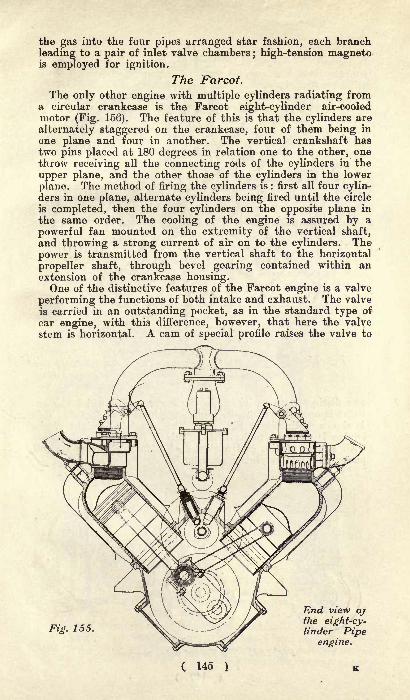
the gas into the four pipes arranged star fashion, each branch
leading to a pair of inlet valve chambers; high-tension magneto
is employed for ignition.
The Farcot.
The only other engine with multiple cylinders radiating froma circular crankcase is the Farcot eight-cylinder air-cooled
motor (Fig. 156). The feature of this is that the cylinders are
alternately staggered on the crankcase, four of them being in
one plane and four in another. The vertical crankshaft hastwo pins placed at 180 degrees in relation one to the other, onethrow receiving all the connecting rods of the cylinders in the
upper plane, and the other those of the cylinders in the lower
plane. The method of firing the cylinders is : first all four cylin-ders in one plane, alternate cylinders being fired until the circle
is completed, then the four cylinders on the opposite plane in
the same order. The cooling of the engine is assured by a
powerful fan mounted on the extremity of the vertical shaft,and throwing a strong current of air on to the cylinders. The
power is transmitted from the vertical shaft to the horizontal
propeller shaft, through bevel gearing contained within anextension of the crankcase housing.One of the distinctive features of the Farcot engine is a valve
performing the functions of both intake and exhaust. The valve
is carried in an outstanding pocket, as in the standard type of
car engine, with this difference, however, that here the valve
stem is horizontal. A cam of special profile raises the valve to
Fig. 155.
End view ojthe eight-cy-linder Pipe
engine.
C 145 )

8
Fig- 156. \%\%^ The eight-cylinder Farcot
engine, showing firingorder.
two distinct open positions, in the lower one of which the ex-
haust is opened, and in the higher the intake is effected. Thisis shown distinctly in Fig. 157. The completed weight of the
engine is declared to be 1251b. This is for the 50h.p. enginewith a bore of 4in. and a stroke of 4.7in., delivering its full
power at 1,600 revolutions a minute.
Exhaust. Inlet.
Fig. 157. The Farcot valve mechanism*
( 146 >
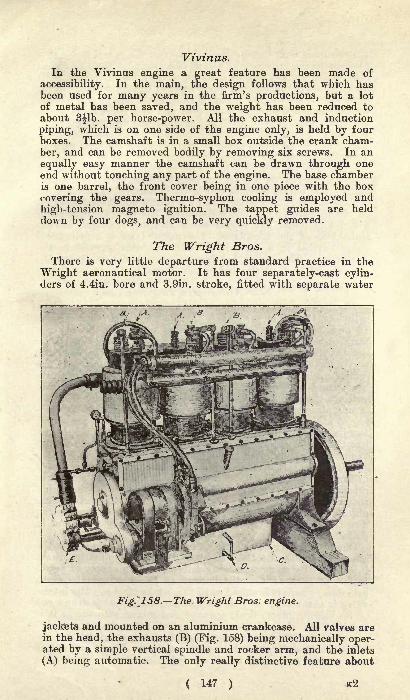
Vivinus.
In the Vivinus engine a great feature has been made of
accessibility. In the main, the design follows that which hasbeen used for many years in the firm's productions, but a lot
of metal has been saved, and the weight has been reduced toabout S^lb. per horse-power. All the exhaust and induction
piping, which is on one side of the engine only, is held by fourboxes. The camshaft is in a small box outside the crank cham-
ber, and can be removed bodily by removing six screws. In an
equally easy manner the camshaft can be drawn through oneend without touching any part of the engine. The base chamberis one barrel, the front cover being in one piece with the box
covering the gears. Thermo-syphon cooling is employed and
high-tension magneto ignition. The tappet guides are held
down by four dogs, and can be very quickly removed.
The Wright Bros.
There is very little departure from standard practice in the
Wright aeronautical motor. It has four separately-cast cylin-ders of 4.4in. bore and 3.9in. stroke, fitted with separate water
Fig.~_158. The< Wright Bros: engine.
jackets and mounted on an aluminium crankcase. All valves arein the head, the exhausts (B) (Fig. 158) being mechanically oper-ated by a simple vertical spindle and rocker arm, and the inlets
(A) being automatic. The only really distinctive feature about
147 ) e2
the engine is that there is no carburetter, the petrol being sup-
plied by direct injection by means of a pump on the right-handside of the engine, worked through worm gear off the camshaftand by a short shaft across the interior of the crankcase. On thesame side of the engine is the lubricating oil pump, also workedoff the camshaft through worm gear and by a short shaft across
the crankcase. The base (C) of the crankcase forms an oil reser-
voir, from which the lubricant is pumped up to the main bear-
ings, then drips down again to the reservoir through pipe D,
being filtered on the way.Ignition of the engine is by means of a high-tension Eisemann
magneto, carried on a platform near the base of the crankcase,and worked off the forward end of the camshaft. The water for
cooling the engine is circulated by a rotary pump (E), mountedon the forward end of the mainshaft. The radiator consists of
a series of plain, flat copper tubes attached to one of thestanchions of the aeroplane. The petrol tank is a cylindricalvessel carried in a vertical position and also secured to the
stanchions. The engine has free exhaust, and has also auxili-
ary exhaust ports at the end of the stroke.
The Antoinette Engine.The most generally employed Antoinette engine has eight
cylinders, though larger models are also made with, respectively,16 and 32 cylinders. The aluminium crankcase, having the
form of a rectangular prism, receives two rows of cylinders oneach of its faces inclined at 45 degrees, the angle between the
two rows of cylinders thus being one of 90 degrees. On the
earlier models the cylinders were cast separately, had separate
heads, and were copper jacketed. The 1909 models have been
entirely changed in this respect, the cylinders being of steel,
in one piece with their heads and valve pockets. The machin-
ing of such a piece is really a work of fine metallic sculpture,the justification for which is found in the decreased weight, 110
less than l^lb. having been gained on each cylinder, or a total
of more than 121b. over the entire engine.The main shaft of the engine has four throws, and is carried
in five bearings. The two rows of cylinders are slightly offset in
relation one to the other, thus allowing the two connectingrods of opposed cylinders to be connected up to the same crank-
pin. The camshaft is carried above the main shaft, and driven
directly off this latter, the valves being side by side, and in
pockets, in the angle formed by the two rows of cylinders.One of the distinctive features of the Antoinette, engine is the
absence of a carburetter, the petrol being supplied by direct
injection. By means of a gear-driven pump, a supply of petrolis fed to each of the distributors at the head of the eight
cylinders, where it is stored until the intake stroke. The intake
valve is automatic, and, on its opening, the petrol is drawn out
of its lodging place, finely sprayed and mixed with air as it is
carried into the cylinder. The petrol pump has a variable
stroke, thus allowing more or less fuel being fed to the dis-
tributors according to the speed required. There is little if
any saving in weight by direct injection, for in place of a
C 148 )

carburetter, a pump, special piping, and distributors have to be
employed ;but the advantage claimed for the system is more
reliable carburation under all conditions. Lubrication of themotor is assured by a gear-driven pump. The propeller, whichis built up with forged steel blades, is generally mounted on theforward extension of the main shaft.
The Greene Engine.The Greene Motor Patents Syndicate, of 55, Berners Street,
W., have produced a special engine for aeroplane work. Thedesign is not new, an engine of this pattern having been con-structed seven years ago, and the fact that it is now beingconstructed by the Aster Engineering Co. vouches for its quality.The reduction in weight has been effected by the employment of
pressed copper water jackets, overhead valve gear, and sheetmetal bottom to the crank chamber. One advantage of usingdetachable water jackets is, of course, that the cylinders canbe machined inside and out to be of uniform thickness. Thewater jacket joint is made with a rubber ring, which, after afew runs on the bench, subject to the heat of the water, becomes
partly vulcanised, remaining soft only at its contact with the
copper. The inlet and exhaust valves are set in cages in thehead of the combustion chamber, and provision is made to pre-vent a valve dropping into the cylinder should it break. Theoverhead camshaft is made in one piece, but the camboxes are
arranged to swing back in sets of four, to give access to thevalves. The rockers actuating the valves have rollers at their
near ends running on the face of the cams, and each is containedin its own oil-tight case. Forced-feed lubrication is employed,and ignition is high-tension magneto. A feature of the mountingof the cylinders is that the holding-down bolts pass throughpillars in the upper crankcase casting, and some of these bolts
are used for the main bearings, which are five in number. Thisenables the crank chamber to be closed underneath by a metal
tray. The engine shown is a four-cylinder GOh.p., developingits power at l,000r.p.m., and weighing 2351b. only, includingpiping, carburetter, etc., but excluding flywheel. A biggerengine, of the same general design, with eight cylinders set" V "
fashion, is used on "Baby," the War Office dirigible of
1909.
New Engine Motor Co.
The engine made by the New Engine Co., Ltd., is a two-stroke motor that differs from others of its kind in that special
scavenging arrangements are provided. At each stroke anenormous volume of air is swept through the cylinders, so that,besides driving out all products of combustion, enough coolingeffect is produced in the pistons and cylinder walls to render
any external water or air-cooling superfluous. To attain this
end, some departures from ordinary practice are, of course,
necessary. The exhaust port is very high up, in fact it openshalf-way down the stroke, and the inlet is just below it. Both
ports are exceptionally large, and a fan, driven off the engine,forces a large volume of air through from inlet to exhaust,
( 149 )
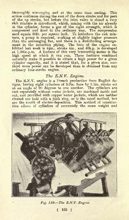
thoroughly scavenging and at the same time cooling. Thisaction continues during the rest of the down stroke and for partof the up stroke, but before the inlet valve is closed a veryrich mixture is introduced, which, mixing with the air alreadyin the cylinder, forms a gas of the right strength, which is
compressed and fired in the ordinary way. The compressionused equals 801b. per square inch. To introduce the rich mix-
ture, a pump is required, working at slightly higher pressure.than the scavenging fan, and there is a distributing arrange-ment in the induction piping. The bore of the engine ex-
hibited last week is 4^in., stroke 4in., and 40h.p. is developedat l,500r.p.m. A feature of this very interesting motor is the
high speed at which it can run. These features combined
naturally make it possible to obtain a high power for a givencylinder capacity, and it is stated that, for a given size, one-
third more power can be developed than is obtained from anyordinary four-stroke engine.
The E.N.V. Engine.The E.N.V. engine is a French production from English de-
signs, having eight cylinders of 3.9in. bore by S.lin. stroke set
at an angle of 90 degrees to one another. The cylinders are
cast separately without water jackets, are machined inside and
out, and provided with copper water jackets, which are neither
riveted nor held with a junk ring, as is the usual method, butare the result of electro-deposition. This method of construc-
tion allows of cylinders of accurately the same weight and
Fig. 159. The E.N.V. Engine.
( 150 )

thickness of wall, while the system of deposit allows the copperto be so closely joined to the cast iron of the cylinder that it is
impossible to say where the copper leaves off and the cast iron
begins. The only disadvantage that can be brought against it
is that of increased cost.
All valves are carried in the angle formed by the two lines
of cylinders, and are operated by a single camshaft, machinedout of the solid and hollowed for lubrication purposes. A dis-
tinctive feature of the camshaft is that it is slidable in a longi-tudinal direction at the will of the operator, thus varying the
lift of the valves. The crankshaft is a fine piece of workman-
ship, with four throws and circular webs, which have the effect
of aiding the flywheel action. The shaft is mounted in plain
bearings of exceptional length, while the crank pins are of the
same diameter as the bearings, each one receiving two con-
necting rods side by side.
The Dutheil-Chalmers.
Dutheil-Chalmers aeronautical engines are all horizontal, andconstructed with two, four, six or more pairs of cylinders, the
most commonly-employed types, however, having respectivelytwo and four cylinders. Where specially light weight is de-
sired, the engines are air cooled, but for all the larger four-
cylinder engines water cooling is employed.The cylinders are opposed and slightly offset in relation one
to the other to allow the connecting rods to be attached to
different pins of the crankshaft.There is a very complete circulation of water around the
cylinder head the part that most needs cooling.The inlet valve on this model is automatic, though we under-
stand that a special model is now being constructed with me-
chanically-operated inlet in conjunction with the exhaust. Theexhaust valve is operated by overhead rocker arm, and is placed
immediately in the head of the cylinder. The valve is guidedfor a considerable length, and allows the gases to exhaust free
into the air;a baffle plate is, however, fitted to prevent the
hot gases coming in contact with the valve spring. The cam-
shaft is carried above the crankshaft and parallel to it, there
being but one cam for two valves.
The high-tension magneto is generally carried on the upperportion of the crankcase, and is geared off the camshaft. Double
ignition is provided by accumulators and coil, and a very in-
genious system is adopted on these motors by which spark
plugs can be changed while the engine is running. The device
consists of a movable plate carrying four plugs, two receivingtheir current from the magneto and two from the accumulators.
By turning the plate round, any one of the plugs can be broughtinto communication with the combustion chamber.
All the engines have a bore of 125 millimetres and a stroke
of 120 millimetres, the normal engine speed being 1,200 revolu-
tions per minute. The two-cylinder engine weighs 1651b. and
gives 20h.p. ;the four-cylinder engine weighs 2641b. and develops
40h.p. ;while the six-cylinder model develops GOh.p. for a total
weight of 3751b.
( 151 )

Aero Motors, Ltd.
The Aero Motors, Ltd., which is under the guiding power ofMr. F. R. Simms, who brought the original Daimler engineto this country, has produced a six-cylinder engine whichdevelops 50h.p. at l,000r.p.ni., weighing only 2201b., this
weight being exclusive of the flywheel and exhaust piping, butincluding water and induction piping, magneto, etc. The cylin-ders are set at 120 degrees to each other, on opposite sides ofthe crankcase, and slightly staggered, in order to bring twobig ends on each crank throw. They are 110mm. bore by110mm. stroke, and are cast separately, with super-imposedvalves in a pocket facing the centre. All the valves are oper-ated from a single central camshaft on the top of the crank-
case, the exhaust valves being operated by a direct push, liftingshoes being fitted between the cams and tappets. The inlet
valves open automatically, but are closed mechanically by a
spring-rotated rocker arm on top of the engine. To permit thevalve to open, this rocker arm is drawn down by a tension rod
operated by a bell-crank pivoted on a spindle above the cam-shaft. One end of the rocking lever carries a shoe which runsover the face of the cam. Gas is supplied from a carburettersituated centrally above the engine, and delivering the mixture
through two branches to a pipe along the top of each set of
cylinders. Forced feed lubrication is employed for the main
bearings and big ends. For the gearwheels, grey fibre is used,with magnolia cheeks. The magneto is mounted on a bracketabove the cranks at the forward end. A rather neat fittingis used to secure the two side plates of the mixture chamberon which the air and mixture throttles are mounted. The
fastening is a simple blade spring attached to the main pipe
pressing on the centre of the plates, which can, of course, thenbe quickly detached.
The Renault.
Air cooling is employed on the Renault eight-cylinder aero-
nautical engine. The cylinders, which have a bore of 90 anda stroke of 120 millimetres, are mounted in the form of a " V >:
on an aluminium crankcase. The two lines of cylinders are
slightly offset, thus allowing two connecting rods to be attachedside by side on a single throw of the crankshaft. The mainshaft is mounted on five bearings.
All the valves are worked off a single camshaft, the inlets
being in outstanding pockets within the angle formed by the
two lines of cylinders, and exhausts immediately above themare operated by rocker arms. The arrangement of the carburet-
ter and inlet piping is somewhat original. The float chamberand nozzle are carried quite on the outside of the engine and
very low down, the top of the carburetter being on a level with
the base of the cylinders. This has been done in order to makeit possible to place the tank in a convenient position to feed by
gravity, instead of by pressure, as is done on most aeroplanes.
Probably the most distinctive feature of the engine is that the
propeller is mounted on the extremity of the camshaft, and not
( 152 )'

on the main shaft. It is now generally recognised that greaterefficiency is obtained from a propeller turning at 600 to 900revolutions a minute than from one running at 1,200 to 1,800revolutions a minute. A suitable reducing gear has been diffi-
cult to find, and it needed the daring of a Wright to adopt thesomewhat clumsy transmission by chain. On the Renault en-
gine no reducing gear is required, the crankshaft turning at half
the speed of the main shaft, giving 900 revolutions per minuteof the propeller with the engine running at full speed. Thecamshaft is specially constructed for the work it has to perform,and is mounted on ball bearings.The engine is enclosed by a light aluminium housing at both
ends and on the top, and even the small amount of space be-tween the cylinders has been closed up by aluminium plates.
Fig. 160. The 8-cylinder air-cooled
Renault engine.
At the rear of the engine, and mounted on the end of the main
shaft, is a powerful centrifugal ventilator, also partially housed,which draws a strong current of air into the V-shaped spaceformed by the cylinders. Everything being closed up, the only
possible escape for the air is between the fins of the cylinders,with the result that these latter are kept at a normal tempera-ture. Ignition is by high-tension magneto, which is carried
within the angle formed by the cylinders. Lubrication is
assured by pump circulation, the supply of oil being carried in
a reservoir forming the extreme base of the crank chamber anddelivered under pressure to the main bearings of the engine.Under brake test the engine gives 55h.p. at 1,800 revolutions,and in full running order, but with tanks empty weighs 3751b.
( 153 )

LIGHT IGNITION APPARATUS.
For special requirements, it is possible to produce ignition
system components much below the weight standard employedfor car use. Although it is improbable that the coil and accu-
mulator system of ignition will become a standard part of theaerial engine's equipment, as the high-tension magneto is, in
every way, better suited, it may be stated that an efficient
trembler coil can be made llb. in weight only, whereas the
ordinary patterns weigh from 41b. up to, in extreme cases, 81b.
For a multiple cylinder engine, a high-tension distributor andcontact to work in conjunction with the specially light coil
would not weigh more than lib. The minimum weight in acoil is only obtainable by the use of materials of the highestquality. The soft iron wire core, the insulating material, andthe copper wire for the primary and secondary windings haveto be specially considered. The core has to be most carefullyannealed and kept to the smallest proportions compatible with
obtaining sufficient magnetic effect. The insulating material is
paraffined silk; this also forms the insulation for the copperwire. On ordinary coils cotton insulation is largely used whichtakes up more space and necessitates a greater weight of wire
being used to obtain a good spark. The use of the finest possible
gauge wire for the secondary coil is an important factor in
making a light coil. On ordinary coils Nos. 36 or 38 gauge is
commonly used, whereas 42 or 44 gauge is required for the lightcoil. Such wire necessitates extremely careful handling to avoid
breakage in the course of winding it, but, as it enables a verylarge number of turns to be made with a given length and weightof wire, and as upon this largely depends the strength of the
spark from the coil, any difficulties are amply compensated for.
The condenser in the ordinary coil accounts for a good propor-tion of the weight, as tinfoil interleaved with paraffined paperis used. For a light coil the condenser is best built up from akind of metallised paper, a material mainly used in telegraphinstruments. The terminals have to be reduced to very small
proportions, and the case is best made of moulded vulcanite.
Wood may be used, but, being necessarily very thin, it is fragileas compared with vulcanite.
Accumulators of the ordinary pattern do not permit of a veryappreciable reduction in weight from the standard ignition
patterns, except at the risk of proving unreliable. The weightcan, if need be, be cut down to one-half the usual weight byusing very thin plates, but, as there is no strength to resist thestress of charging and discharging, such plates easily buckle and
go to pieces. This defect can be minimised by giving extra
support to the plates by means of special bridge pieces. Thethin plate is also at a disadvantage, in that it lacks the depthof active material necessary to give it a good working capacity.Extra light cells have been made by dispensing with the usual
( 154 )
lead grid, into which the active material, the lead oxide, is
pressed. A skeleton lead frame with a series of pockets or ledgesis formed which supports loose granules of active material.
This is mounted in a perforated celluloid envelope. This cell is
about one-half the weight of the usual plate pattern. The
Schmitt, a French-made cell, is constructed on this principle.Another cell of specially light construction is the Lithanode,in which the active material is formed in blocks and the amountof inactive lead in the plates is considerably reduced. In theFors cell, one of the electrodes consists of a porous pot con-
taining lead peroxide instead of the usual positive plate. This
makes a light cell of high capacity.
High-tension magneto machines, suitable for firing a single-
cylinder engine, can be obtained at a weight of 41b., exclusive
of the driving sprocket or pinion, and for a six or eight-cylinder
engine a special type with distributor can be had at 71b. Inthe Ruthardt machine special lightness is obtained by elimi-
nating the usual iron pole pieces and a number of the minor
fittings, besides using aluminium for the base and frame of the
machine. The magnets consist of flat steel rings with the polar
space bored out. The absence of pole pieces gives a good mag-netic circuit arid a strong
"field of force
" at minimum weight.It is not possible to save much weight in the armature, as there
must be a definite amount of wire and soft iron to produce a
spark of sufficient firing intensity, and there is also the con-
denser, which must have a given capacity, to consider. Modifi-
cation in the mechanical parts and design alone give much scopefor weight saving. In the Simms aero magneto, a light machineof high power is obtained by the use of aluminium where
practicable and the employment of the highest workmanshipthroughout. The Nieuport machine is of the specially light,
simple, and compact type, and is distinctive, in that it has no
high-tension distributor, as ordinarily fitted. The current is
drawn direct off collecting rings on the armature shaft, and a
peculiarity is that two sparks occur simultaneously in the engine,one in a cylinder concluding its exhaust stroke and the other in
a cylinder completing its compression stroke. These machines
range from 4lb. for a single-cylinder upwards, and the absenceof the distributor makes the machine considerably simpler in
construction than the ordinary type. The Bosch and Nilmelior
(Bassee-Michel) machines are made in small and light models,the former being 4flb. and the latter 61b. There is considerable
difference in the magnet system of the various machines. Inone type a single magnet is used, whilst in others there are two
pairs of double magnets, one placed over the other, and in a
few other machines there are three pairs. A powerful magnetsystem is an advantage for starting by insuring a strong sparkat low speeds, but, necessarily, this entails extra weight in themachine.
( 155 )
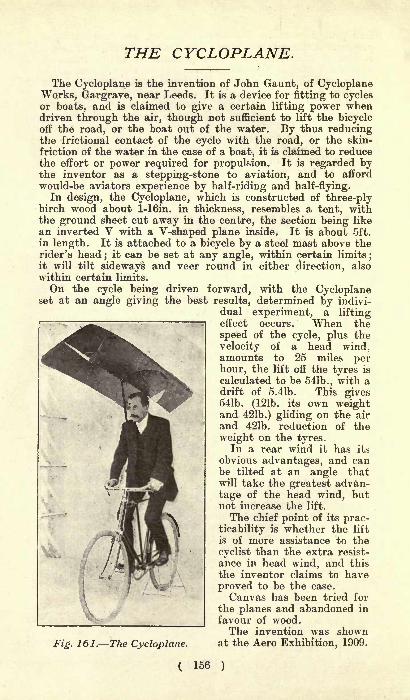
THE CYCLOPLANE.
The Cycloplane is the invention of John Gaunt, of CycloplaneWorks, Gargrave, near Leeds. It is a device for fitting to cyclesor boats, and is claimed to give a certain lifting power whendriven through the air, though not sufficient to lift the bicycleoff the road, or the boat out of the water. By thus reducingthe frictional contact of the cycle with the road, or the skin-
friction of the water in the case of a boat, it is claimed to reducethe effort or power required for propulsion. It is regarded bythe inventor as a stepping-stone to aviation, and to afford
would-be aviators experience by half-riding and half-flying.In design, the Cycloplane, which is constructed of three-ply
birch wood about 1-16in. in thickness, resembles a tent, withthe ground sheet cut away in the centre, the section being like
an inverted V with a V-shaped plane inside. It is about 5ft.
in length. It is attached to a bicycle by a steel mast above therider's head
;it can be set at any angle, within certain limits
;
it will tilt sideways and veer round in either direction, also
within certain limits.
On the cycle being driven forward, with the Cycloplaneset at an angle giving the best results, determined by indivi-
dual experiment, a liftingeffect occurs. When the
speed of the cycle, plus the
velocity of a head wind,amounts to 25 miles perhour, the lift off the tyres is
calculated to be 541b., with adrift of 5.41b. This gives541b. (121b. its own weightand 421b.) gliding on the air
and 421b. reduction of the
weight on the tyres.In a rear wind it has its
obvious advantages, and canbe tilted at an angle thatwill take the greatest advan-
tage of the head wind, butnot increase the lift.
The chief point of its prac-ticability is whether the lift
is of more assistance to the
cyclist than the extra resist-
ance in head wind, and this
the inventor claims to have
proved to be the case.
Canvas has been tried for
the planes and abandoned in
favour of wood.The invention was shown
Fig. 161. The Cycloplane. at the Aero Exhibition, 1909.
( 156 )
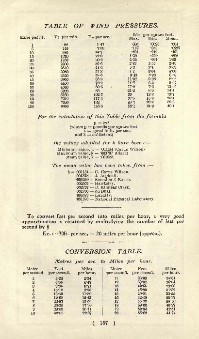
TABLE OF WIND PRESSURES.
Miles per hr. Ft. per min. Ft. per sec.Lbs. per square foot.
Max. Min. Mean.
1
51015202530354045505560708090100
440880132017602200
44004840
70407920
1-47
7-33
14-722-0
44-0
51-3
58-6
66-073-380-688102-7117-3132146-6
For the calculation of this Table from the formulap = kv2
(where p = pounds per square feet
v = speed in ft. per sec.
and k = coefficient)
the values adopted for k have been :
Minimum value, k = -001154 (Carus Wilson)Maximum value, k = -002737 (Clark)
Mean value, k = -001855.
The mean value has been taken from :
k= -001154 C. Carus Wilson.001378 J. Aspinall.002330 Smeaton & Rouse.002502 Hawksley.002737 D. Kinnear Clark.001700 du Buat.001670 Langley.001370 National Physical Laboratory.
To convert feet per second into miles per hour, a very goodapproximation is obtained by multiplying the number of feet persecond by .
Ex. : 30ft- per sec, = 20 miles per hour (approx.).
CONVERSION TABLE.
Metres per sec. to Miles per hour.
Metre Feetper second, per second.
1 3-28
9-8413-12
16-4019-68
22-97
29-5382-81
( 157 )
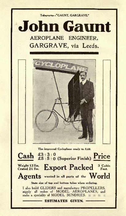
Telegrams-"GAUNT, GARGRAVE."
John GauntAEROPLANE ENGINEER,
GARGRAVE, via Leeds.
CashThe improved Cycloplane ready to fold.
3:3:0
Weight 1 2 Ibs,
Crated 21 Ibs.
5 : 5 : (Superior Finish)
Export Packed
Price
3 CubicFeet.
wanted in all parts of the
State size of top and bottom tubes when ordering.
I also build GLIDERS and manufacture PROPELLERS,supply all makes of MODEL AEROPLANES, and
make a speciality of MODEL SUNDRIES. :: :: :: ::
ESTIMATES GIVEN.

THE
COMMERCIAL-MOTORS
Conducted byEDMUND DANGERFIELD.
Editor :
EDWARD SHRAPNELL SMITH.Manager :
ERNEST PERMAN.
THISjournal fosters, re-
presents and chroniclescommercial motoring in
all its branches. It has the
largest and best circulation
throughout the UnitedKingdom, the Colonies, Indiaand foreign countries gener-
ally. :: "The CommercialMotor" is Officially Recog-nised by The CommercialMotor Users' Association,and is the Official Organ of
the Society of Road Traction
Engineers.
Fully Illustrated.
Printed and Published by TEMPLE PRESS LTD.,7-15, ROSEBERY AVENUE, LONDON, B.C., forthe Proprietors, COMMERCIAL PRESS LTD.
Every ^^2^^^F ONEThursday. ^^^^ PENNY
THE
M010RROAT
Ev$ry Thursday,
ONE PENNY.


Rl
RETURN TO the circulation desk of any
University of California Library
or to the
NORTHERN REGIONAL LIBRARY FACILITY
Bldg. 400, Richmond Field Station
University of California
Richmond, CA 94804-4698
ALL BOOKS MAY BE RECALLED AFTER 7 DAYS2-month loans may be renewed by calling
(510)642-6753
1-year loans may be recharged by bringing booksto NRLF
Renewals and recharges may be made 4 daysprior to due date
DUE AS STAMPED BELOW
_ APR 18 1994

YB 70008
7Z ^-6-
A3
UNIVERSITY OF CALIFORNIA LIBRARY
" The well-known aeronautical experts, who have
gained most encouraging success with machinesbuilt by them, and whose wide experience provesof immense assistance/'
AEROCRAFT, 1st July, 1909,
DO YOU WANT /TO BUILD AFLYING MACHINE? We supply
every part*
ARE YOU DESIROUS OF HAVINGYOUR INVENTIONS CARRIEDOUT? We wiU build exactly to yourspecification*
ARE YOU REQUIRING PRO-PEELERS? The Handley Page is
lightest and strongest. Guaranteedthrust and H.P, absorb.
ARE YOU REQUIRING ANYACCESSORIES ? We supply
WIRESTRAINERSe
6s.PER DOZEN,
BAMBOO,TUBING,WIRES,WHBEI&
We specialise in Gliders and all types ofAerocrsft.
e*THE HOUSE FOR AW, THINGS PERTAININGTO AVIATION."
KANDLEY PAGE, LTD.72, VICTORIA STREET, LONDON, S.W
Works: Woolwich, S,E.
W*tef Entfcnd: Bridgw&w? Motor Co.,
Brldswattr,


![Bengal Excise Act, 1909 - Excise Directorate of West ...wbexcise.gov.in/writereaddata/BengalExciseAct.pdf · THE BENGAL EXCISE ACT, 1909 [Bengal Act V of 1909] 8th September, 1909.](https://static.fdocuments.us/doc/165x107/5e93c84c0cdb4c286613454c/bengal-excise-act-1909-excise-directorate-of-west-the-bengal-excise-act.jpg)

