Canon DM-MV600i, DM-MV630i, DM-MV600, DM-MV590 Digital Camcorder

(English) DM-E8000-04
Dealer's Manual
ROAD MTB Trekking
City Touring/Comfort Bike
URBAN SPORT E-BIKE
E8000 SeriesSC-E8000SC-E6010SW-E8000-LSW-M9050-RSW-M8050-RSW-E6010RD-M9050RD-M8050FC-E8000FC-E8050FC-M8050SM-CRE80SM-CRE80-BSM-CDE80DU-E8000SM-DUE10SM-DUE11SM-DUE80-ASM-DUE80-BBT-E8010BT-E8020BM-E8010BM-E8020
TL-FC39RT-EM800RT-EM900

ii
CONTENTSIMPORTANT NOTICE .......................................................................................................... iv
TO ENSURE SAFETY ............................................................................................................ v
Chapter1 LIST OF TOOLS TO BE USED 1-1
LIST OF TOOLS TO BE USED ............................................................................................1-2
Chapter2 INSTALLATION 2-1
INSTALLATION ..................................................................................................................2-2Names of parts ...................................................................................................................................................2-2
Product specifications........................................................................................................................................2-3
Installing the cycle computer ............................................................................................................................2-4
Installing and removing the cycle computer (SC-E6010) .................................................................................2-6
Adjusting the angle of the cycle computer (SC-E6010) ...................................................................................2-6
Installing the assist switch .................................................................................................................................2-7
Using the cable band to attach the assist switch to the handlebar ...............................................................2-8
Installing the assist switch .................................................................................................................................2-9
Connecting the electric wire ...........................................................................................................................2-10
Installing the battery mount .........................................................................................................................2-13
Installing / removing the battery ....................................................................................................................2-22
Installing the speed sensor .............................................................................................................................2-26
Mounting the magnet ....................................................................................................................................2-27
Chapter3 INSTALLING AND WIRING THE DRIVE UNIT 3-1
INSTALLING AND WIRING THE DRIVE UNIT ...................................................................3-2Installing the drive unit .....................................................................................................................................3-2
Drive unit wiring diagram ................................................................................................................................3-3
Connecting the power cord ..............................................................................................................................3-4
Connecting switches and the drive unit to the cycle computer (SC-E8000) ..................................................3-5
Connecting the assist switch and drive unit to the cycle computer (SC-E6010) ............................................3-5
Connecting the speed sensor to the drive unit ...............................................................................................3-6
Connecting the light cable to the drive unit ...................................................................................................3-7
Installing the crank and front chainring ..........................................................................................................3-8

iii
Chapter4 CHARGING THE BATTERY 4-1
CHARGING THE BATTERY ................................................................................................4-2Proper use of the battery ..................................................................................................................................4-2
Charging the battery .........................................................................................................................................4-3
About the charger LED lamp ............................................................................................................................4-5
About the battery LED lamps ...........................................................................................................................4-5
Turning the power ON / OFF .............................................................................................................................4-8
Chapter5 HOW TO OPERATE 5-1
HOW TO OPERATE ...........................................................................................................5-2About the functions of the assist switches and shift switches ........................................................................5-2
Cycle computer display and setting .................................................................................................................5-3
Battery level indicator .......................................................................................................................................5-4
Assist mode ........................................................................................................................................................5-5
Switching between displayed traveling data ..................................................................................................5-7
About the setting menus ..................................................................................................................................5-9
Error messages on the cycle computer ...........................................................................................................5-27
Chapter6 CONNECTION AND COMMUNICATION WITH DEVICES 6-1
CONNECTION AND COMMUNICATION WITH DEVICES .................................................6-2About wireless functions ..................................................................................................................................6-2
2.4 GHz digital wireless system .........................................................................................................................6-3
Drive unit setting backup function for the cycle computer ...........................................................................6-3
Settings customizable in E-TUBE PROJECT .......................................................................................................6-4
Connecting to the PC ........................................................................................................................................6-6
Chapter7 MAINTENANCE 7-1
MAINTENANCE ................................................................................................................7-2Replacing the clamp band ................................................................................................................................7-2
Replacing the front chainring ..........................................................................................................................7-3
Replacing the guide of the chain device .........................................................................................................7-4

iv
IMPORTANT NOTICE
IMPORTANT NOTICE
• This dealer's manual is intended primarily for use by professional bicycle mechanics. Users who are not professionally trained for bicycle assembly should not attempt to install the components themselves using the dealer's manuals. If any part of the information on the manual is unclear to you, do not proceed with the installation. Instead, contact your place of purchase or a local bicycle dealer for their assistance.
• Make sure to read all instruction manuals included with the product.
• Do not disassemble or modify the product other than as stated in the information contained in this dealer’s manual.
• All dealer’s manuals and instruction manuals can be viewed on-line on our website (http://si.shimano.com).
• Please observe the appropriate rules and regulations of the country, state or region in which you conduct your business as a dealer.
• The Bluetooth® word mark and logos are registered trademarks owned by the Bluetooth SIG, Inc. and any use of such marks by SHIMANO INC. is under license. Other trademarks and trade names are those of their respective owners.
For safety, be sure to read this dealer’s manual thoroughly before use, and follow it for correct use.
The following instructions must be observed at all times in order to prevent personal injury and physical damage to equipment and surroundings.The instructions are classified according to the degree of danger or damage which may occur if the product is used incorrectly.
DANGER
Failure to follow the instructions will result in death or serious injury.
WARNING
Failure to follow the instructions could result in death or serious injury.
CAUTION
Failure to follow the instructions could cause personal injury or physical damage to equipment and surroundings.

v
TO ENSURE SAFETY
TO ENSURE SAFETY
DANGER
Be sure to also inform users of the following:
�Handling the battery • Do not deform, modify, disassemble or apply solder directly to the battery. Doing so may cause leakage, overheating, bursting, or ignition of the battery.
• Do not leave the battery near sources of heat such as heaters. Do not heat the battery or throw it into a fire. Doing so may cause bursting or ignition of the battery.
• Do not subject the battery to strong shocks or throw it. If this is not observed, overheating, bursting, or fire may occur.
• Do not place the battery into fresh water or sea water, and do not allow the battery terminals to get wet. Doing so may cause overheating, bursting, or ignition of the battery.
• Use the Shimano specified charger and observe the specified charging conditions when charging the specified battery. Not doing so may cause overheating, bursting, or ignition of the battery.
WARNING
• Be sure to follow the instructions provided in the manuals when installing the product.It is recommended that you use only genuine Shimano parts. If parts such as bolts and nuts become loose or damaged, the bicycle may suddenly fall over, which may cause serious injury. In addition, if adjustments are not carried out correctly, problems may occur, and the bicycle may suddenly fall over, which may cause serious injury.
• Be sure to wear safety glasses or goggles to protect your eyes while performing maintenance tasks such as replacing parts.
• For information on products not explained in this manual, refer to the manuals provided with each product.
• After reading the dealer's manual thoroughly, keep it in a safe place for later reference.
Be sure to also inform users of the following: • Be careful not to let yourself be distracted by the cycle computer display while riding the bicycle. Otherwise, you may fall off the bicycle.
• Before riding, check that the wheels are secured. Otherwise, you may fall off the bicycle and be seriously injured.
• Be sufficiently familiar with how to start the power assisted bicycle before riding on busy streets. Otherwise, you may start the bicycle abruptly and have an accident.
• Make sure that the light is on during night riding.
• Do not disassemble the product. Disassembling it may cause injury to persons.
• When charging the battery while it is installed on the bicycle, do not move the bicycle. The battery charger’s power plug may not be completely inserted into the outlet, which may lead to fire.

vi
TO ENSURE SAFETY
�Lithium Ion Battery • If any liquid leaking from the battery gets into your eyes, immediately wash the affected area thoroughly with clean water such as tap water without rubbing your eyes, and seek medical advice immediately. If this is not done, the battery liquid may damage your eyes.
• Do not recharge the battery in very humid places or the outdoors. If this is not observed, electric shocks may result.
• Do not insert or remove the plug while it is wet. If this is not observed, electric shocks may result. If there is water leaking out of the plug, dry it thoroughly before inserting it.
• If the battery does not become fully charged after 6 hours of charging, immediately unplug the battery from the outlet and contact the place of purchase. Not doing so may cause overheating, bursting, or ignition of the battery.
• Do not use the battery if it has any noticeable scratches or other external damage. Doing so may cause bursting, overheating or problems with operation.
• The operating temperature ranges for the battery are given below. Do not use the battery in temperatures outside these ranges. If the battery is used or stored in temperatures outside these ranges, fire, injury or problems with operation may occur. 1. During discharge: –10 °C - 50 °C2. During charging: 0 °C - 40 °C
�Items related to installation to and maintenance of the bicycle • Be sure to remove the battery and charger before wiring or attaching parts to the bicycle. Otherwise, an electric shock may result.
• Be sure to follow the instructions provided in the manuals when installing the product. It is recommended that you use only genuine Shimano parts. If bolts and nuts become loose or the product is damaged, the bicycle may suddenly fall over, resulting in a serious injury.
• Maintenance interval depends on the usage and riding circumstances. Clean regularly the chain with an appropriate chain cleaner. Never use alkali based or acid based solvents such as rust cleaners. If those solvent be used chain might break and cause serious injury.
CAUTION
Be sure to also inform users of the following: • Observe the instructions in the user's manual for the bicycle, in order to ride safely.
• Periodically check the battery charger and adapter, particularly the cord, plug, and case, for any damage. If the charger or adapter is broken, do not use it until it has been repaired.
• Use the product under the direction of a safety supervisor or the directions for use. Do not allow physically, sensory, or mentally impaired persons, inexperienced persons, or persons with no required knowledge including children to use this instrument.
• Do not allow children to play near the product.
• If any malfunction or trouble occurs, consult the dealer nearest you.
• Never modify the system. This may cause a malfunction in the system.
�Lithium Ion Battery • Do not leave the battery in a place exposed to direct sunlight, inside a vehicle on a hot day, or other hot places. This may result in battery leakage.
• If any leaked fluid gets on your skin or clothes, wash it off immediately with clean water. Otherwise, the leaked fluid may damage your skin.
• Store the battery in a safe place out of the reach of infants and pets.

vii
TO ENSURE SAFETY
NOTE
Be sure to also inform users of the following: • Be sure to attach dummy plugs to any unused ports.
• For installation and adjustment of the product, consult a dealer.
• The units are designed to be fully waterproof to withstand wet weather riding conditions. However, do not deliberately place them into water.
• Do not clean the bicycle with a high-pressure washer. If water gets into any of the components, operating problems or rusting may result.
• Handle the components carefully, and avoid subjecting them to any strong shocks.
• Do not place the bicycle upside down. Doing so may damage the cycle computer or shift switch.
• Although the bicycle still functions as a normal bicycle even when the battery is removed, the light does not turn on if it is connected to the electric power system. Be aware that using the bicycle under these conditions will be considered non-observance of the road traffic laws in Germany.
• When carrying the bicycle in a car, remove the battery from the bicycle and place it on a stable surface in the car.
• Before connecting the battery, make sure that there is no buildup of water or dirt in the connector where the battery will be connected.
• When charging the battery while it is mounted on the bicycle, be careful of the following:
- When charging, make sure there is no water on the charging port or the charger plug.
- Check that the battery mount is locked before charging.
- Do not remove the battery from the battery mount while charging.
- Do not ride the bicycle with the battery charger mounted on.
- Close the charging port cap when not charging.
- Stabilize the bicycle to ensure that it does not collapse during charging.
• The use of a genuine Shimano battery is recommended. If using a battery from another manufacturer, make sure to carefully read the instruction manual for the battery before use.
• Some of the important information in this dealer's manual can also be found on the device labels.
• The number found on the battery key is necessary when purchasing spare keys. Store it carefully.
• Use a damp cloth, with the water well wrung out, when cleaning the battery and plastic cover.
• If you have any questions about the use and maintenance of the product, consult the dealer where you made the purchase.
• Contact the place of purchase for updates of the component software. The most up-to-date information is available on the Shimano website. For details, refer to the "CONNECTION AND COMMUNICATION WITH DEVICES" section.
• Products are not guaranteed against natural wear and deterioration from normal use and aging.
• For maximum performance we highly recommend Shimano lubricants and maintenance products.
�Connection and communication with PCA PC linkage device can be used to connect a PC to the bicycle (system or components), and E-TUBE PROJECT can be used to carry out tasks such as customizing single components or the whole system and updating firmware.
• PC linkage device: SM-PCE1
• E-TUBE PROJECT: PC application
• Firmware: software inside each component
�Connection and communication with smartphone or tabletIt is possible to customize single components or the system, and update firmware, using E-TUBE PROJECT for smartphones/tablets after connecting the bicycle (system or components) to a smartphone or tablet via Bluetooth LE.
• E-TUBE PROJECT: app for smartphones/tablets
• Firmware: software inside each component

viii
TO ENSURE SAFETY
�Lithium Ion Battery
Disposal information for countries outside the European UnionThis symbol is only valid within the European Union.Follow local regulations when disposing of used batteries. If you are not sure, consult the place of purchase or a bicycle dealer.
�Items related to installation to and maintenance of the bicycle • Do not use thinner or other solvents to clean any of the components. Such substances may damage the surfaces.
• You should periodically wash the chainrings in a neutral detergent. In addition, cleaning the chain with neutral detergent and lubricating it can be an effective way of extending the useful life of the chainrings and the chain.
The actual product may differ from the illustration because this manual is intended chiefly to explain the procedures for using the product.

Chapter1 LIST OF TOOLS TO BE USED

1-2
Chapter1 LIST OF TOOLS TO BE USED
LIST OF TOOLS TO BE USED
The following tools are needed for installation, adjustment, and maintenance purposes.
Component Where to use Tool
Cycle computers
(SC-E8000)Clamp bolt 3 mm hexagon wrench
Cycle computers
(SC-E6010)
Handlebar fixing bolt Screwdriver [#2]
Angle adjustment screw Screwdriver [#2]
Assist switch
(SW-M9050/SW-E8000)
Unit fixing bolt 3 mm hexagon wrench
Lever fixing bolt 2 mm hexagon wrench
Assist switch
(SW-E6010)Fixing bolt 3 mm hexagon wrench
Electric wire Connector TL-EW02
Battery mount
(BM-E8010)
Mount lower case 3 mm hexagon wrench / 8 mm spanner
Key unit 3 mm hexagon wrench
Key unit cover 2.5 mm hexagon wrench
Mount upper case 2.5 mm hexagon wrench

1-3
Chapter1 LIST OF TOOLS TO BE USED
Component Where to use Tool
Battery mount
(BM-E8020)
Mount lower case 5 mm hexagon wrench
Mount upper case Screwdriver [#2]
Key cylinder 2 mm hexagon wrench
Key unit 5 mm hexagon wrench
Key unit cover Screwdriver [#2]
Speed sensor
(SM-DUE10)Speed sensor fixing bolt 4 mm hexagon wrench
Speed sensor
(SM-DUE11)Speed sensor fixing bolt Hexalobular [#10]
Magnet unit Fixing bolt Screwdriver [#2]
Light cable Mounting bolt Screwdriver [#2]
Drive unit
Drive unit fixing bolt (M8) - -
Cover fixing bolt (M3) Screwdriver [#2]
Crank arm
Cap TL-FC16/TL-FC18
Stopper plate 5 mm hexagon wrench
Chain device
Guide fixing bolt (M5) 4 mm hexagon wrench
Back plate fixing bolt (M6) 3 mm hexagon wrench
Front chainring Lock ring TL-FC39+TL-FC36

Chapter2 INSTALLATION

2-2
Chapter2 INSTALLATION
Names of parts
INSTALLATION
� Names of parts
(D) (I)
(J)
(M)
(A)
(B)
(L)
(C)
(E)
(N)
(H)
(F)
(G)
(K)
(P) (O) (O)
(A) Cycle computer: SC-E8000 SC-E6010
(B) Assist switch: SW-E8000-L
(C) Front chainring: SM-CRE80/SW-E6010
(D) Chain device: SM-CDE80
(E) Crank arm: FC-E8000/FC-E8050/FC-M8050
(F) Drive unit: DU-E8000
(G) Speed sensor: SM-DUE10
(H) Drive unit cover: SM-DUE80-A (type that covers drive unit ports) SM-DUE80-B (type that covers drive unit ports and the frame installation bolts)
(I) Battery (external type)/ Battery mount (external type): BT-E8010/BM-E8010
(J) Battery charger: EC-E6000
(K) Battery (built-in type)/ Battery mount (built-in type): BT-E8020/BM-E8020
(L) E-TUBE (EW-SD50)
When using electronic gear shifting(M) Shifting switch:
SW-M9050-R/SW-M8050-R SW-E6010
(N) Rear derailleur (DI2): RD-M9050/RD-M8050
(O) Speed sensor: SM-DUE11
(P) Disc brake rotor: RT-EM800/RT-EM900
TECH TIPS
Maximum cable length (EW-SD50)(L) ≤ 1,600 mm

2-3
Chapter2 INSTALLATION
Product specifications
� Product specifications
Operating temperature range:
During discharge-10 – 50 °C Battery type Lithium Ion Battery
Operating temperature range:
During charging0 – 40 °C Nominal capacity
Refer to the user's manual for the
battery "UM-70F0A". For the latest
information on manuals, see the
website (http://si.shimano.com).
Storage temperature -20 – 70 °C Rated voltage 36 V DC
Storage temperature (Battery) -20 – 60 °C Drive unit type Midship
Charging voltage 100 – 240 V AC Motor type Brush-less DC
Charging time
Refer to the user's manual for the
battery "UM-70F0A". For the latest
information on manuals, see the
website (http://si.shimano.com).
Rated drive unit power 250 W
* The maximum speed up to which power assistance is provided is set by the manufacturer and is conditional on where the bicycle is to be used.

2-4
Chapter2 INSTALLATION
Installing the cycle computer
� Installing the cycle computer
SC-E8000
1
(A)
(B)
Pass the clamp band on the cycle computer over the handlebar.
(A) Clamp band
(B) Cycle computer
2
(A)
Adjust the angle of the cycle computer so that it is easy to see, and then use a 3 mm hexagon wrench to tighten the clamp bolt.
(A) Clamp bolt
Tightening torque
0.8 N·m
NOTE
Recommended installation angle of the information display: Between 15° to 35° to the horizontal.
35°
15°

2-5
Chapter2 INSTALLATION
Installing the cycle computer
SC-E6010
1 Open the clamp (B) and attach it to the handlebar.
2
(B)
(C)
(A)
Attach the handlebar fixing bolt (A) and tighten to the specified tightening torque using a screwdriver.
(A) Handlebar fixing bolt
(B) Clamp
(C) Adapter
Handlebar compatibility tableøA øB-øA Adapter Fixing bolt
ø23.4-ø24 0-1.1 X 15.5 mm
ø24-ø25.5 0-1.1 X 20 mm
ø31.3-ø31.9 0-0.6 - 20 mm
* X: OKHandlebar
øA øB
25
30
Tightening torque
1 N·m
TECH TIPS
When removing the cycle computer, reverse the procedure.

2-6
Chapter2 INSTALLATION
Installing and removing the cycle computer (SC-E6010)
� Installing and removing the cycle computer (SC-E6010)
1
(A)
(B)
Slide the cycle computer (A) into the bracket (B) as shown in the illustration.Insert it firmly until you hear it click.
(A) Cycle computer
(B) Bracket
2(C)
To remove the cycle computer, slide it while pushing the bracket lever (C).
(C) Lever
NOTE
If the cycle computer is not in the correct place, the assist function will not operate normally.
� Adjusting the angle of the cycle computer (SC-E6010)
(A)
Loosen the angle adjustment screw (A) with a screwdriver. Adjust the angle of the cycle computer to make it easier to see while riding.After determining the angle, tighten the screw to the designated torque.
(A) Angle adjustment screw
Tightening torque
0.5 N·m

2-7
Chapter2 INSTALLATION
Installing the assist switch
� Installing the assist switch
SC-E8000
1
(B) (A) Pass the assist switch over the handlebar. (A) Handlebar
(B) Assist switch
TECH TIPS
Supported handlebars: Ø22.0 mm/Ø22.2 mm/Ø22.5 mm
2
(A)
Adjust the attachment position and angle, and then use a hexagon wrench to tighten the unit fixing bolt.
(A) Unit fixing bolt
Tightening torque
2 - 2.2 N·m
NOTE
Attach the lever in a position where it will not touch the brake lever when pushed all the way in.
3
(A)
[X]
[Y]
Adjust the positions of lever [X] and lever [Y].
Loosen the lever fixing bolt using an 2 mm hexagon wrench, and adjust the lever's position so that it is easy to push.
After determining the position, tighten to the designated torque.
(A) Lever fixing bolt
Tightening torque
0.5 - 0.7 N·m

2-8
Chapter2 INSTALLATION
Using the cable band to attach the assist switch to the handlebar
� Using the cable band to attach the assist switch to the handlebar
SW-E6010
1
(A)
Temporarily attach the cable band (A) to the assist switch. Adjust the cable band according to the length of the handlebar.
(A) Cable band
TECH TIPS
The cable band is included in SW-E6010.
2
Attach the assist switch mounted with the cable band to the handlebar.

2-9
Chapter2 INSTALLATION
Installing the assist switch
� Installing the assist switch
1 (A)
(B)
Attach the assist switch to a ø 22.2 handlebar with the electric wire routed under the switch and open the fixing bolt cover (A).
(A) Fixing bolt cover
(B) Fixing bolt
2
Tighten the fixing bolt (B) to the specified tightening torque using a 3 mm hexagon wrench.
Tightening torque
1.5 N·m
TECH TIPS
When removing the cycle computer, reverse the procedure.

2-10To be continued on next page
Chapter2 INSTALLATION
Connecting the electric wire
� Connecting the electric wire
Set so that the projection on the connector is aligned with the groove in the narrow end.
(A)
(B)
(A) TL-EW02
(B) Plug
NOTE
Use the Shimano original tool for installation and removal of the electric wire.When installing the electric wire, do not forcibly bend the plug. It may result in a poor contact. When connecting the electric wire, push it in until it clicks in place.
Connect the electric wire to the assist switch
1 (A)
Remove the cable cap from the assist switch.
(A) Cable cap
2 (A)(B)
Pass the electric wire through the cable cap, and connect it to the assist switch.
(A) Cable cap
(B) Electric wire
NOTE
Make sure the electric wire is connected through the cable cap. If the wire is not passed through the cable cap, the electric wire connector may be damaged.

2-11
Chapter2 INSTALLATION
Connecting the electric wire
3
When routing the electric wire in the direction of the stem
When using a cable built-in handlebar
(A)
Install the cable cap.
When routing the electric wire along a cable built-in handlebar, run the wire along the guide of the cable cap then the handlebar.
(A) Guide
Securing the electric wire (SC-E8000)
(A)
(B) (C)
Bind the brake horse (or brake outer casing) to the electric wire connecting the cycle computer and drive unit, using the band, as shown in the illustration.
(A) Electric wire of the cycle computer
(B) Brake horse (or brake outer casing)
(C) Band
TECH TIPS
The band is included in SC-E8000.

2-12
Chapter2 INSTALLATION
Connecting the electric wire
Example of routing the electric wire (SW-E6010)
(C)(B)(A)
(D)
Example 1: Secure the electric wire of the assist switch (A) to the handlebar using the cable band (B). Wind the excess electric wire around the area between the cycle computer (C) and stem (D), then connect the wire to the cycle computer.
(A) Assist switch
(B) Cable band
(C) Cycle computer
(D) Stem
(G)
(F)(E)
Example 2: Secure the electric wire of the assist switch to the handlebar using the cable band. Bind the electric wire of the assist switch and that of the cycle computer (E) to the brake outer casing (F) using the band (G) and connect the electric wire of the assist switch to the cycle computer.
(E) Electric wire of the cycle computer
(F) Brake outer casing
(G) Band
TECH TIPS
The band is included in SC-E6010.

2-13To be continued on next page
Chapter2 INSTALLATION
Installing the battery mount
� Installing the battery mount
BM-E8010
(A)
(B)
(E)
(y)
(z)
(D)
(C)
(y) Front of bicycle
(z) Rear of bicycle
(A) Key unit
(B) Battery connection unit
(C) Mount upper case
(D) Mount lower case
(E) Frame
1
(B)
(C)
(D)
(E)
(A)
Set in place the rubber spacers and metal spacer on the mount lower case and align the frame mounting holes with the bolt holes in the mount lower case.
(A) Mount lower case
(B) Metal spacer
(C) Rubber spacer
(D) Frame
(E) Frame mounting holes

2-14To be continued on next page
Chapter2 INSTALLATION
Installing the battery mount
2
(A)
(C)
(B)
Secure the mount lower case by tightening the two types of mount fixing bolt (M5).
Tighten the mount fixing bolt (M5) (low head type) first.
(A) Mount fixing bolt (M5) (hexagon bolt type): Use a 3 mm hexagon wrench or 8 mm spanner on the mount fixing bolt.
(B) Mount fixing bolt (M5) (low head type): Use a 3 mm hexagon wrench on the mount fixing bolt.
(C) Mount lower case
Tightening torque
3 N·m
3
(C)
(A)
(C)
(B)Temporarily attach the key unit with the key unit fixing bolts (M5).
(A) Key unit: Key unit is not included with Shimano products.
(B) Key unit fixing bolt (M5)
(C) Washer
4
(B)(A)
224.4 mm
Adjust the position of the key unit so that the distance between section (A) of the key unit and section (B) of the mount lower case is 224.4 mm and then fully tighten the key unit fixing bolts.
Tightening torque
3 N·m

2-15To be continued on next page
Chapter2 INSTALLATION
Installing the battery mount
5
(A)
(B)
Temporarily attach the key unit cover to the key unit and adjust so that the battery can be smoothly connected/disconnected and no noise is produced due to looseness during riding.
(A) Key unit cover
(B) Battery
6
(A)(B)
(B)
Secure the key unit cover with the key unit cover fixing bolts (M4).
(A) Key unit cover
(B) Key unit cover fixing bolt (M4)
Tightening torque
0.6 N·m

2-16
Chapter2 INSTALLATION
Installing the battery mount
7
(A)
(B)
(C)
(E)
(D)
Route the power cord through the cable routing hole.
Align the protruding parts of the mount upper case and mount lower case.
Pull the power cord until the rubber bush is implanted in the cable routing hole.
(A) Power cord
(B) Cable routing hole
(C) Mount upper case
(D) Mount lower case
(E) Rubber bush
8 (A)
(B)
(C)
(C)
Tighten on the mount upper case using the mount upper case fixing bolts (M3).
(A) Mount upper case
(B) Mount lower case
(C) Mount upper case fixing bolt (M3)
Tightening torque
0.6 N·m

2-17To be continued on next page
Chapter2 INSTALLATION
Installing the battery mount
BM-E8020
Assembly of the battery connection unit
(A)
(C)
(y)
(z)(B)
(y) Front of bicycle
(z) Rear of bicycle
(A) Frame
(B) Battery connection unit
(C) Mount upper case and mount lower case when assembled
1
(A)
(B) (C)
Align the frame mounting holes with the bolt holes in the mount lower case.
(A) Mount lower case
(B) Frame
(C) Frame mounting holes
2-18To be continued on next page
Chapter2 INSTALLATION
Installing the battery mount
2
(A)
(B)
(C)
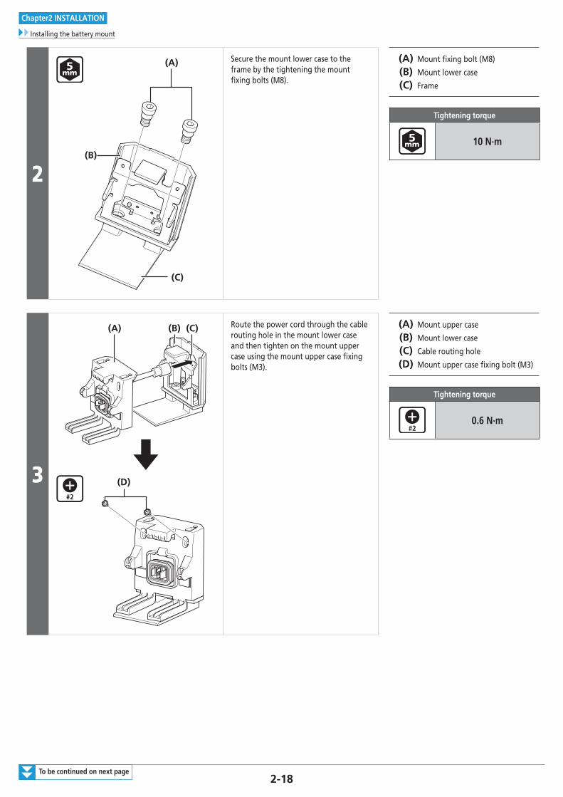
Secure the mount lower case to the frame by the tightening the mount fixing bolts (M8).
(A) Mount fixing bolt (M8)
(B) Mount lower case
(C) Frame
Tightening torque
10 N·m
3
(A)
(D)
(B) (C) Route the power cord through the cable routing hole in the mount lower case and then tighten on the mount upper case using the mount upper case fixing bolts (M3).
(A) Mount upper case
(B) Mount lower case
(C) Cable routing hole
(D) Mount upper case fixing bolt (M3)
Tightening torque
0.6 N·m

2-19To be continued on next page
Chapter2 INSTALLATION
Installing the battery mount
Assembly of the key unit
(A)(y)
(z)(B)
(y) Front of bicycle
(z) Rear of bicycle
(A) Frame
(B) Key unit
4
(C)
(z)
(A)
(B)
Insert the key cylinder into the key unit.
Secure the key cylinder in place by tightening the key cylinder fixing bolts (M4) from the reverse side of the key unit.
(z) Reverse side of key unit
(A) Key cylinder: Key cylinder is not included with Shimano products.
(B) Key unit
(C) Key cylinder fixing bolt (M4)
Tightening torque
0.6 N·m

2-20To be continued on next page
Chapter2 INSTALLATION
Installing the battery mount
5
(A)
(D)
(C) (B)
(E)
(B) (C)
Align the fixing bolt holes in the key unit with the frame mounting holes.
Temporarily attach the key unit to the frame with the key unit fixing bolts (M8).
Attach the bolt fork end prevention rubbers.
(A) Key unit
(B) Key unit fixing bolt (M8)
(C) Bolt fork end prevention rubber
(D) Frame
(E) Frame mounting holes
6
(A) (B)
347.2 mm
Adjust the position of the key unit so that the distance between section (A) of the key unit and section (B) of the battery connection unit is 347.2 mm and then fully tighten the key unit fixing bolts.
Tightening torque
10 N·m
7 (B)
(A)
Temporarily attach the key unit cover to the key unit and adjust so that the battery can be smoothly connected/disconnected and no noise is produced due to looseness during riding.
(A) Key unit cover
(B) Battery

2-21
Chapter2 INSTALLATION
Installing the battery mount
8
(C)
(A)(B)
Attach the key unit cover to the key unit.
Secure in place the key unit with the key unit fixing bolts (M3).
(A) Key unit cover
(B) Key unit
(C) Key unit cover fixing bolt (M3)
Tightening torque
0.6 N·m

2-22
Chapter2 INSTALLATION
Installing / removing the battery
� Installing / removing the battery
Installation of the battery
BT-E8010
1
Align the indentation in the bottom of the battery with the protrusion on the mount and insert the battery.
2
Slide the battery to the right starting from the point where it is inserted.
Push in the battery until you hear it click.
3
Return the key to the locking position, remove it, and store it in a safe place. NOTE
• To prevent the battery from falling out, check to see that the battery is locked after installation.
• Before riding, make sure that the charging port cap is closed.
• To prevent the battery from falling out, do not ride the bicycle with the key inserted.

2-23
Chapter2 INSTALLATION
Installing / removing the battery
BT-E8020
(B)
(A)
Insert the battery into the battery mount until there is a click.
• When inserted until a click is heard, the battery is locked automatically.
(A) Battery
(B) Battery mount
NOTE
• To prevent the battery from falling out, check to see that the battery is locked after installation.
• Before riding, make sure that the keyhole cap and charging port cap are closed.
• To prevent the battery from falling out, do not ride the bicycle with the key inserted.
Keyhole cap
Charging port cap

2-24
Chapter2 INSTALLATION
Installing / removing the battery
Removing the battery
The following description may not be applicable as different types of keys are available.
BT-E8010
1
(A)
(B)
Turn off the power, then insert the key into the key cylinder in the battery holder.
(A) Key
(B) Key cylinder
NOTE
Hold the battery firmly and be careful that it does not drop when removing or carrying it.
TECH TIPS
• The position of the key does not affect the insertion of the battery. You can insert it regardless of the key position.
• You cannot remove the key when it is not in the inserting position.
2
To unlock the battery turn the key to the left until you feel some resistance.
3
Hold the upper part of the battery and slide it to the left to remove it.

2-25
Chapter2 INSTALLATION
Installing / removing the battery
BT-E8020If using a battery cover manufactured by another company, remove the battery cover before removing the battery.
1
(A)
Remove the keyhole cap. (A) Key hole cap
2
(B)
(A) Insert the key into the key cylinder in the battery mount.
(A) Key cylinder
(B) Key
TECH TIPS
• The position of the key does not affect the insertion of the battery. You can insert it regardless of the key position.
• You cannot remove the key when it is not in the inserting position.
3
To unlock the battery, turn the key clockwise and push it in.
4
Remove the key from the key cylinder, close the keyhole cap, and detach the battery.
NOTE
• Support the battery with your hand when detaching to make sure that it does not fall out.
• Do not attach or detach the battery with the key left inserted into the key cylinder or the keyhole cap left open. The battery may be damaged from contact with the handle of the key or the keyhole cap.

2-26
Chapter2 INSTALLATION
Installing the speed sensor
� Installing the speed sensor
SM-DUE10
1 (B)
(A)
(D)
(C)
(a)
Before installing the speed sensor, check that the clearance (a) between the speed sensor and the magnet unit will be within 3 to 17 mm.
(A) Speed sensor
(B) Magnet unit
(C) Spoke
(D) Chain stay
TECH TIPS
When checking the clearance is within 17 mm, take wheel truing, frame distortion, etc. into account.
2
(A) (B)
If the clearance is within the designated range, place the toothed washer between the speed sensor and the chain stay, then attach the speed sensor fixing bolt.
(A) Toothed washer
(B) Speed sensor fixing bolt (16 mm)
Tightening torque
1.5 - 2 N·m
3
(A) (B)
If the clearance exceeds 17 mm, use a spacer to adjust it.
Attach the speed sensor with the speed sensor fixing bolt.
(A) Spacer
(B) Speed sensor fixing bolt (22 mm)
Tightening torque
1.5 - 2 N·m
SM-DUE11
1 (A)(A)
Install the speed sensor with the 2 speed sensor fixing bolts.
(A) Speed sensor fixing bolt
Tightening torque
0.6 N·m

2-27
Chapter2 INSTALLATION
Mounting the magnet
� Mounting the magnet
SM-DUE10
Magnet mounting position
Mount the magnet so that its center is aligned over the apex of the triangle symbol.
How to mount the magnet
1
(A)
(B)
(C)
Align the speed sensor and magnet unit as shown in the illustration.
(A) Speed sensor
(B) Magnet unit
(C) Spoke
2
(A)
Tighten the fixing bolt with a screwdriver.
(A) Fixing bolt
Tightening torque
1.5 - 2 N·m

2-28
Chapter2 INSTALLATION
Mounting the magnet
SM-DUE11
(B)
(A)
Use the special magnet model for the disc brake rotor.
(A) Magnet unit
(B) Speed sensor
NOTE
Refer to General Operations for installation of the disc brake rotor.

Chapter3 INSTALLING AND WIRING THE DRIVE UNIT

3-2
Chapter3 INSTALLING AND WIRING THE DRIVE UNIT
Installing the drive unit
INSTALLING AND WIRING THE DRIVE UNIT
� Installing the drive unit
Route the cables before installing the drive unit.
1
(A)
(B)
Align the drive unit with the three mounting holes on the right side and left side of the frame.
(A) Mounting holes
(B) Drive unit
NOTE
Be careful not to pinch the cables with the frame or drive unit case.
2
Right side
(y)
Left side
(z)
First attach the drive unit fixing bolts (M8) to the right side.
After this, attach the drive unit fixing bolts (M8) to the left side.
Tighten the drive unit fixing bolts (M8) until the drive unit makes firm contact with the inside of the right side of the frame.
(y) Front of bicycle
(z) Rear of bicycle
TECH TIPS
Drive unit fixing bolts (M8) are not included with Shimano products. Use those supplied by the manufacturer. Tighten the bolts to the following tightening torque when attaching the drive unit to the frame.
Tightening torque
10 - 12.5 N·m
3-3
Chapter3 INSTALLING AND WIRING THE DRIVE UNIT
Drive unit wiring diagram
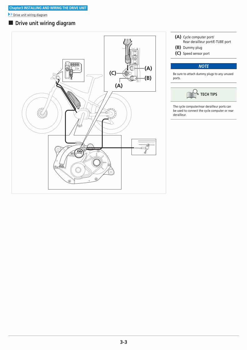
� Drive unit wiring diagram
(C)(A)
(B)(A)
(A) Cycle computer port/ Rear derailleur port/E-TUBE port
(B) Dummy plug
(C) Speed sensor port
NOTE
Be sure to attach dummy plugs to any unused ports.
TECH TIPS
The cycle computer/rear derailleur ports can be used to connect the cycle computer or rear derailleur.

3-4
Chapter3 INSTALLING AND WIRING THE DRIVE UNIT
Connecting the power cord
� Connecting the power cord
Connecting to the drive unit
(B)
(A)
Align the arrow on the power cord with the triangle symbol on the drive unit port and insert the power cord.
Insert it until it locks into place.
(A) Power cord
(B) Drive unit port
Disconnecting from the drive unit
To remove the power cord, hold it by the grooved part of its end and pull it towards yourself.

3-5
Chapter3 INSTALLING AND WIRING THE DRIVE UNIT
Connecting switches and the drive unit to the cycle computer (SC-E8000)
� Connecting switches and the drive unit to the cycle computer (SC-E8000)
Use the TL-EW02 for connection. (A) Cycle computer
(B) Assist switch
(C) Shift switch
(D) Drive unit
(E) TL-EW02
NOTE
Be sure to attach dummy plugs to any unused ports.
TECH TIPS
The electric wire connector can be connected to any port of the cycle computer, but we recommend you connect the assist switch to the switch-side port.
(A)(B) (C)
(D)
(E)
� Connecting the assist switch and drive unit to the cycle computer (SC-E6010)
Use the TL-EW02 (D) for connection. (A) Cycle computer
(B) Assist/Shift switch
(C) Drive Unit
(D) TL-EW02
TECH TIPS
The electric wire connector can be connected to any port of the cycle computer, but we recommend you connect the assist switch to the switch-side port.
(A)
(B)
(C)
(D)
(B)

3-6
Chapter3 INSTALLING AND WIRING THE DRIVE UNIT
Connecting the speed sensor to the drive unit
� Connecting the speed sensor to the drive unit
Connect the speed sensor unit electric wire to the drive unit speed sensor port using the TL-EW02. (A) TL-EW02
(B) Speed sensor port
(B)
(A)

3-7
Chapter3 INSTALLING AND WIRING THE DRIVE UNIT
Connecting the light cable to the drive unit
� Connecting the light cable to the drive unit
1
(B)
(A)
Remove the crank and drive unit cover and loosen the mounting bolts of the light connection terminals.
(A) Light connection terminals
(B) Mounting bolt
TECH TIPS
For information on compatible lights, contact a manufacturer of completed bicycles.
2(B)(A)
Attach the front light cable and tail light cable to the terminals and secure them with the mounting bolts.
(A) Front light cable
(B) Taillight cable
Tightening torque
0.6 N·m
3
(A)
Attach the drive unit cover.
Tighten the cover fixing bolts (M3) in the three locations.
(A) Cover fixing bolt (M3)
Tightening torque
0.6 N·m

3-8To be continued on next page
Chapter3 INSTALLING AND WIRING THE DRIVE UNIT
Installing the crank and front chainring
� Installing the crank and front chainring
Perform the procedure below for all models, regardless of whether gear shifting is electrical or mechanical.
1
(A) (B)
(D)(C)
Align the wide part of the left crank arm with the wide part of the front chainring through axle and then attach.
(A) Wide groove area (left crank arm)
(B) Wide part (front chainring through axle)
(C) Left crank arm
(D) Axle spacer
NOTE
Left or right is indicated on each crank arm. Check the L and R markings when installing.
L R
Left crank arm Right crank arm
2
(A) (B)
Use the Shimano original tool to tighten the cap.
(A) TL-FC16/TL-FC18
(B) Cap
Tightening torque
0.7 - 1.5 N·m

3-9
Chapter3 INSTALLING AND WIRING THE DRIVE UNIT
Installing the crank and front chainring
3
(A)
(B)
(z)
(C)
Push in the stopper plate and check that the plate pin is securely in place, and then tighten the bolt of the left crank arm.
Tighten both bolts equally to the specified tightening torque (12 - 14 N·m).
(z) The illustration is of the left crank arm (cross-section)
(A) Plate pin
(B) Stopper plate
(C) Left crank arm
Tightening torque
12 - 14 N·m
NOTE
• The two bolts should be tightened at the same time rather than each bolt being fully tightened separately.
• Set the stopper plate in the correct direction as shown in illustration.
4
(A)Attach the drive unit cover.
Tighten the cover fixing bolts (M3) in the three locations.
(A) Cover fixing bolt (M3)
Tightening torque
0.6 N·m
5
(A) (B)
If using a chain device, temporarily tighten the back plate to the mounting member of the front chainring.
(A) Back plate fixing bolt (M6)
(B) Back plate
To be continued on next page

3-10To be continued on next page
Chapter3 INSTALLING AND WIRING THE DRIVE UNIT
Installing the crank and front chainring
6
(B)(A)
Align the cutout in the front chainring with the wide area of the front chainring mounting member when attaching the front chainring.
(A) Front chainring (SM-CRE80-B)
(B) Chainring mounting member
NOTE
• Use the front chainring and chain device combinations specified in the table.
Front chainring Chain device
SM-CRE80
(34T/38T CL:
50 mm)
Frame mount type
SM-CRE80
(44T CL: 50 mm
Double chain
guard)
-
SM-CRE80-B
(34T/38T CL:
53 mm)
Drive unit mount
type
• Note the difference between the front and back of the chainring. The front has a gear size (tooth number) marking.
Front
Back
7
(A)
Mount the chain on the chainring. (A) Chain
NOTE
When mounting the chain, make sure to match chainring tooth thickness (thick/thin) and chain inner width (wide/narrow).

3-11To be continued on next page
Chapter3 INSTALLING AND WIRING THE DRIVE UNIT
Installing the crank and front chainring
8
(y)(z) (A)
(B)
Determine the position of the guide according to the number of teeth on the crank.
Install the guide by temporarily tightening the guide fixing bolt (M5)
(y) 38T
(z) 34T
(A) Guide
(B) Guide fixing bolt (M5)
9(A)
(z)
(B)
(C)
(D)
If using a chain device, after attaching the chain, rotate the back plate so that the clearance between the chain and the rubber band is 0-1 mm.
Adjustment should be performed under the following conditions.
• Chain is engaging the smallest sprocket
• Rear suspension is fully extended
After adjustment, fully tighten the back plate and guide.
(z) 0 - 1 mm
(A) Rubber band
(B) Chain
(C) Guide fixing bolt (M5) (4 mm hexagon wrench)
(D) Back plate fixing bolt (M6) (3 mm hexagon wrench)
Tightening torque
4 N·m
5 - 7 N·m
NOTE
If the chain and chain device interfere with each other when SM-CDE80 is used on a bicycle with Rear suspension at sag position , please adjust angle the chain device not to touch chain in the position of Low gear.

3-12To be continued on next page
Chapter3 INSTALLING AND WIRING THE DRIVE UNIT
Installing the crank and front chainring
10
(B)
(A)
Tighten the lock ring by hand and attach the Shimano original tool.
While holding the left crank, tighten the lock ring in the direction shown in the illustration.
(A) TL-FC39/TL-FC36
(B) Lock ring
Tightening torque
35 - 45 N·m
NOTE
• If using a torque wrench, use TL-FC39 in combination with TL-FC33.
TL-FC39 TL-FC33
• An impact wrench cannot be used.
TECH TIPS
• The lock ring has a left hand thread.
• Combine the Shimano original tools as in the illustration. Set TL-FC39 to TL-FC36 using the 2 installation holes on TL-FC39.
TL-FC36
Installation hole
TL-FC39

3-13
Chapter3 INSTALLING AND WIRING THE DRIVE UNIT
Installing the crank and front chainring
11 (A)
(B)(C)
Install the right crank arm.
Use the Shimano original tool to tighten the cap.
(A) Cap
(B) Right crank arm
(C) Axle spacer
Tightening torque
0.7 - 1.5 N·m
12
(A)
(B)
(z)
(C)
Push in the stopper plate and check that the plate pin is securely in place, and then tighten the bolt of the right crank arm.
Tighten both bolts equally to the specified tightening torque (12 - 14 N·m).
(z) The illustration is of the right crank arm (cross-section)
(A) Plate pin
(B) Stopper plate
(C) Right crank arm
Tightening torque
12 - 14 N·m
NOTE
• The two bolts should be tightened at the same time rather than each bolt being fully tightened separately.
• Set the stopper plate in the correct direction as shown in illustration.

Chapter4 CHARGING THE BATTERY

4-2
Chapter4 CHARGING THE BATTERY
Proper use of the battery
CHARGING THE BATTERY
The battery cannot be used immediately after purchase as it will be in deep sleep mode. Charging the battery with the dedicated battery charger will release the battery from deep sleep mode, allowing the battery to be used. The battery can be used when the LED on it turns on. The battery can also be released from deep sleep mode by connecting to E-TUBE PROJECT when the bicycle is fitted with all components.
� Proper use of the batteryCharging can be carried out at any time regardless of the amount of charge remaining, but you should fully charge the battery in the following cases. Be sure to use the dedicated charger to charge the battery.
• The battery is uncharged at the time of shipment. Before riding, be sure to charge the battery until it is fully charged.
If the battery has become completely discharged, charge it as soon as possible. If you leave the battery uncharged, the battery may deteriorate.
• If the bicycle will not be ridden for a long period of time, store it away with approximately 70% battery capacity remaining. In addition, take care not to let the battery become completely empty by charging it every 6 months.
• Do not connect to E-TUBE PROJECT while the battery is being charged.
The use of a genuine Shimano battery is recommended. If using a battery from another manufacturer, make sure to carefully read the instruction manual for the battery before use.
• Connect to E-TUBE PROJECT and click [Connection check] to confirm whether the battery in use is a genuine Shimano battery or another brand.

4-3
Chapter4 CHARGING THE BATTERY
Charging the battery
� Charging the battery
When charging the battery alone
Battery charger: EC-E6000 Battery: BT-E8010/BT-E8020
1 Connect the battery charger’s power plug to the outlet.
2
BT-E8010
(A)
(B)
BT-E8020
(A) (B)
Insert the charging plug into the battery's charging port.
(A) Charging port
(B) Battery
NOTE
Charge the battery on a flat surface indoors.

4-4
Chapter4 CHARGING THE BATTERY
Charging the battery
When charging the battery while it is mounted on the bicycle
Battery charger: EC-E6000 Battery: BT-E8010/BT-E8020
1 Connect the charger’s power plug to the outlet.
2
BT-E8010
(A)(C)(B)
BT-E8020
(A)
(B)
(C)
Insert the charging plug into the battery mount charging port.
(A) Battery mount
(B) Charging port
(C) Charging plug
TECH TIPS
• Place the battery charger on a steady surface such as the floor before charging.
• Stabilize the bicycle to ensure that it does not collapse during charging.

4-5
Chapter4 CHARGING THE BATTERY
About the charger LED lamp
� About the charger LED lamp
(A)
After charging has started, the LED lamp on the charger lights up.
You can check the current charging status on the battery level lamp located on the battery.
Lit up
Charging
(Within 1 hour after
the completion of
charging)
BlinkingCharging error
Turned off
Battery disconnected
(1 hour or more after
the completion of
charging)
(A) Charger LED lamp
DANGER
Use the battery and charger combination specified by the company for charging and follow the charging conditions specified by the company. Not doing so may cause overheating, bursting, or ignition of the battery.
NOTE
If the bicycle is stored for an extended period of time immediately after purchase, you will need to charge the battery before using the bicycle. Once the battery is charged, it starts to deteriorate slightly.
� About the battery LED lamps
(A)
(A) Battery LED lamp
Charging-in-progress indication
Battery level indication *1 Battery level
0% - 20%
21% - 40%
41% - 60%
61% - 80%
81% - 99%
100%
* 1 : No light : Lit up : Blinking

4-6
Chapter4 CHARGING THE BATTERY
About the battery LED lamps
Battery level indication
The current battery level can be checked by pressing the battery's power button.
Battery level indication *1 Battery level
100% - 81%
80% - 61%
60% - 41%
40% - 21%
20% - 1%
0%
(When battery is not installed on bicycle)
0%, Power off / Shutdown
(When battery is installed on bicycle)
* 1 : No light : Lit up : Blinking
NOTE
When remaining battery capacity is low, system functions begin to shut off in the following order.1. Power assistance (Assist mode automatically switches to [ECO] and then assistance shuts off. The
switch to [ECO] occurs earlier if a battery-powered light is connected.)2. Gear shifting3. Light

4-7
Chapter4 CHARGING THE BATTERY
About the battery LED lamps
Error indication
System errors and similar warnings are indicated by the battery LED lamps through various lighting patterns.
Error indication type Indication condition Lighting pattern *1 Recovery
System errorCommunication error with
the bicycle system
Make sure that the cable is not loose or improperly connected.
If the situation does not improve, contact an agency.
Temperature
protection
If the temperature exceeds
the guaranteed operating
range, the battery output is
turned off.
Leave the battery in a cool place away from direct sunlight until the
internal temperature of the battery decreases sufficiently.
If the situation does not improve, contact an agency.
Security
authentication error
This is displayed if a
genuine drive unit is not
connected.
This is displayed if any of
the cables are
disconnected.
Connect a genuine battery and drive unit.
Check the condition of the cables.
If the situation does not improve, contact an agency.
Charging errorThis is displayed if an error
occurs during charging.
Remove the connector between the battery and charger, and press
the power switch with only the battery connected.
If an error appears with only the battery connected, contact an
agency.
Battery malfunctionElectrical failure inside the
battery
Connect the charger to the battery and then remove the charger.
Press the power switch with only the battery connected.
If an error appears with only the battery connected, contact an
agency.
* 1 : No light : Lit up : Blinking

4-8
Chapter4 CHARGING THE BATTERY
Turning the power ON / OFF
� Turning the power ON / OFF
Turning the power ON and OFF via the cycle computer
< SC-E6010 >
(A)
Hold down the power button (A) on the cycle computer for 2 seconds.
(A) Power button
NOTE
If built-in battery of cycle computer isn't charged sufficiently, the power will not turn on.The built-in battery of the cycle computer is charged only when the cycle computer screen is on.
Turning the power ON and OFF via the battery
BT-E8010
(A)
BT-E8020
(A)
Press the power button on the battery.
The LED lamps will light up indicating remaining battery capacity.
(A) Power button
NOTE
• When turning on the power, check that the battery is firmly attached to the holder.
• Power cannot be turned on while charging.
• Do not place your foot on the pedals when turning on. A system error may result.
TECH TIPS
• To force power off, hold down the power button for 6 seconds.
• If the bicycle has not moved for over 10 minutes, the power will automatically turn off. (Automatic power off function)

Chapter5 HOW TO OPERATE

5-2
Chapter5 HOW TO OPERATE
About the functions of the assist switches and shift switches
HOW TO OPERATE
� About the functions of the assist switches and shift switches
The following explains the operation procedure for cases where the switch settings are set to the default values.
XY
SW-E8000-L
A X Y
SW-M8050-R(SW-M9050-R)
SW-E8000-L SW-M8050-R (SW-M9050-R)
X Switching assist modes: the level of assistance becomes stronger X Shifting gears: pedaling becomes heavier
Y Switching assist modes: the level of assistance becomes weaker Y Shifting gears: pedaling becomes lighter
A Changing the cycle computer display
< SW-E6010 >
X
AY
XAY
AChanging the cycle computer display
Switching between automatic and manual gear shifting
XWhen switching assist modes: the level of assistance becomes stronger
When shifting gears: pedaling becomes heavier
YWhen switching assist modes: the level of assistance becomes weaker
When shifting gears: pedaling becomes lighter

5-3
Chapter5 HOW TO OPERATE
Cycle computer display and setting
� Cycle computer display and setting
Basic screen display of the cycle computer
SC-E8000
(A) (B)
(C)(D)(E)
SC-E6010
(A)
(B)
(G)
(H)
(C)(D)
(E)
(F)
(A) Battery level indicatorDisplays the current battery level.
(B) Gear position (Only displays when electronic gear shifting is in use)Displays the currently set gear position.
(C) Assist gaugeDisplays the assistance.
(D) Assist mode displayDisplays the current assist mode. (Assist mode automatically switches to [ECO] as remaining battery capacity declines. The switch to [ECO] occurs earlier if a battery - powered light is connected.)
(E) Current speedDisplays the current speed.The display can be switched between km/h and mph.
(F) Current timeShows the current time.
(G) Icon to indicate when the light is onNotifi es you when the battery-powered light is on.
(H) Traveling data displayDisplays the current traveling data.

5-4
Chapter5 HOW TO OPERATE
Battery level indicator
� Battery level indicator
SC-E8000
Display Battery level
81 - 100%
61 - 80%
41 - 60%
21 - 40%
1 - 20%*
0%
SC-E6010
Display Battery level
100%
0%
Displays the current battery level by level icon and percentage.
(A) Battery level indicator
TECH TIPS
* The battery level indicator blinks red when remaining battery capacity falls to this level.

5-5
Chapter5 HOW TO OPERATE
Assist mode
� Assist mode
SC-E8000
(A)
SC-E6010
(A)
(A) Assist mode display
Changing assist mode
XY
SW-E8000-L/SC-E8000
SW-E6010/SC-E6010
X
Y
BOOST
WALK
TRAIL
ECO
OFF
Press X or Y to switch assist modes.
BOOST: Assist boostTRAIL: Assist trailECO: Assist ecoOFF: Assist offWALK: Walk assist
: Short press X : Short press Y
: Long press Y : Short press X (This operation is for
canceling [WALK] mode)
NOTE
The Walk assist mode function may not be able to be used in certain regions.

5-6
Chapter5 HOW TO OPERATE
Assist mode
Switching to [WALK] mode (walk assist mode)
1
Y
Y
SW-E8000-L/SC-E8000
SW-E6010/SC-E6010
SC-E8000
SC-E6010
With your feet off the pedals and current speed at [0 km/h], hold down Y until [WALK] displays.
NOTE
• The Walk assist mode function may not be able to be used in certain regions.
• A warning tone will sound while switching is in progress if it is not possible to switch to [WALK] mode because the current speed is not [0 km/h] or there is pressure on the pedals etc.
TECH TIPS
• If Y is not pressed for one minute or more, the mode active before [WALK] mode was set, is re-activated.
• If the bicycle is not moved after [WALK] mode is activated, walk assist is automatically inactivated. To re-activate [WALK] mode, momentarily release Y and then hold down Y.
• The walk assist function can operate at a maximum of 6 km/h.
• The assistance level and speed vary with the gear position.
• The intelligent walk assist function activates when an electric shifting system such as XTR, DEORE XT SEIS is connected. System individually supplies assist power to detect gear position. "Intelligent walk assist" support rider more torque output in steep climb condition in lower side gears. "Quick walk assist" function works quickly by holding down SW from any mode.
2 Release Y when [WALK] displays.
3 Hold down Y again to activate walk assist. • Walk assist remains active provided Y is being held down.
4To cancel [WALK] mode, release Y and press X.
• When [WALK] mode is canceled, the mode active before [WALK] mode was set, is re-activated.

5-7
Chapter5 HOW TO OPERATE
Switching between displayed traveling data
� Switching between displayed traveling data
(A)
(A) Traveling data display
SW-E8000-L/SC-E8000
SW-E6010/SC-E6010
A
A
(A) DST CLOCK (H)
(B) ODO CADENCE (G)
(C) RANGE MAX (F)
(D) TIME AVG (E)
The type of traveling data displayed changes each time you press A.
(A) Traveling distance
(B) Cumulative distance
(C) Maximum traveling distance *1, 3
(D) Traveling time (optional) *2
(E) Average speed (optional) *2
(F) Maximum speed (optional) *2
(G) Number of crank rotations *2
(H) Current time
*1 When [RANGE] is displayed, the battery level is not displayed. The traveling range should be used as a reference only.
*2 Optional item: You can configure the display settings in E-TUBE PROJECT. For details, refer to "CONNECTION AND COMMUNICATION WITH DEVICES"-"Settings customizable in E-TUBE PROJECT".
*3 When walk assistance is functioning, the on screen display [RANGE] changes to [RANGE ---].
NOTE
• The Walk assist mode function may not be able to be used in certain regions.
• When traveling data is displayed, the screen returns to speed display after 60 seconds. When speed data is displayed, pressing A changes the traveling data displayed starting with [DST].
TECH TIPS
Holding down A when DST is displayed clears all traveling data.

5-8
Chapter5 HOW TO OPERATE
Switching between displayed traveling data
Clearing the traveling distance
You can clear the traveling distance in the main screen.
1 Change the traveling data display to [DST] and press A for 2 seconds.
2
Release the finger when the [DST] indication starts blinking.
In this state, pressing A again clears the traveling distance.
TECH TIPS
• The [DST] indicator light stops blinking and the screen takes you back to the basic screen after leaving it alone for 5 seconds.
• When the traveling distance is cleared, [TIME], [AVG] and [MAX] are also cleared.

5-9
Chapter5 HOW TO OPERATE
About the setting menus
� About the setting menus
Accessing the setting menu (SW-E8000-L/SC-E8000)
1
Hold down A when the bicycle is not moving to display the menu list screen.
A
2
A
XY
(A) Clear Exit (L)
(B) ClockRD protection
reset(K)
(C) Bluetooth LE Adjust (J)
(D)Bluetooth
LE/ANTLanguage (I)
(E) Light Unit (H)
(F) Brightness Beep (G)
Press X or Y to select the various menus.
Press A to display the setting screen for the selected menu.
(A) Clear settings
(B) Clock setting
(C) Bluetooth LE pairing
(D) Bluetooth LE/ANT connection status
(E) Turning the light on/off
(F) Display backlight brightness setting
(G) Turning the beep noise on/off
(H) Switching between km and miles
(I) Language setting
(J) Adjusting the electronic gear shifting unit
(K) Activating RD Protection Reset*
(L) Return to the main screen
TECH TIPS
* In order to protect the system from falling down etc., if the bicycle is subjected to a strong impact, the RD Protection function will operate and the connection between the motor and the link will be momentarily severed so that the rear derailleur can no longer operate. Executing RD Protection Reset restores the connection between the motor and the link, as well as the function of the rear derailleur.

5-10
Chapter5 HOW TO OPERATE
About the setting menus
Accessing the setting menu (SW-E6000/SW-E6010/SC-E6010)
1
Hold down X and Y when the bicycle is not moving to display the menu list screen.
X
Y
2
X
Y
A
(A) Clear Exit (K)
(B) Clock RD
protection
reset
(J)
(C) Backlight
(D) Brightness Adjust (I)
(E) Beep Font color (H)
(F) Unit Language (G)
Press X or Y to select the various menus. Press A to display the setting screen for the selected menu.
[Start mode] and [Auto] are displayed on the menu list screen; however, they are not available for use.
(A) Clear settings
(B) Clock setting
(C) Turning the display backlight on/off
(D) Display backlight brightness setting
(E) Turning the beep noise on/off
(F) Switching between km and miles
(G) Language setting
(H) Changing the font color
(I) Adjusting the electronic gear shifting unit
(J) Activating RD Protection Reset*
(K) Return to the main screen
TECH TIPS
* In order to protect the system from falling down etc., if the bicycle is subjected to a strong impact, the RD Protection function will operate and the connection between the motor and the link will be momentarily severed so that the rear derailleur can no longer operate. Executing RD Protection Reset restores the connection between the motor and the link, as well as the function of the rear derailleur.

5-11
Chapter5 HOW TO OPERATE
About the setting menus
Clear
Reset the traveling distance to default.
1
XY
SW-E8000-L/SC-E8000
SW-E6010/SC-E6010
X
Y
SC-E8000
SC-E6010
Press X or Y to select [DST].
SC-E8000/SC-E6010Configurable
itemsDetails
ExitReturn to the menu list
screen
DSTClearing the traveling
distance
SC-E6010Default value set in the SC display setting
Configurable
itemsDefault value
Backlight ON
Beep ON
Unit km
Language English
Brightness 3
Font color White
2A
To reset traveling distance, select [OK] using X or Y and press A to confirm.
After resetting, the screen will automatically return to the menu list screen.
A reset confirmation screen is not displayed on SC-E6010.
TECH TIPS
When the traveling distance is cleared, [TIME], [AVG] and [MAX] are also cleared.

5-12
Chapter5 HOW TO OPERATE
About the setting menus
Clock
Configure the Clock setting.
1XY
SW-E8000-L/SC-E8000
SW-E6010/SC-E6010
X
Y
Press X or Y to adjust the time. TECH TIPS
Press X to increase the numbers.Press Y to decrease the numbers.
2
SW-E8000-L/SC-E8000
SW-E6010/SC-E6010
A
A
Pressing A enables the set value and moves you to the minutes setting.
3 Press X or Y to set the minutes. TECH TIPS
You can change the numbers quickly by holding down X or Y.4 Pressing A enables the set value and takes you back to the Setting menu screen.

5-13To be continued on next page
Chapter5 HOW TO OPERATE
About the setting menus
Bluetooth LE (SC-E8000)
E-TUBE PROJECT for smartphones/tablets may be used if a Bluetooth LE connection is established with a smartphone/tablet.
1 Before setting up a connection, turn on Bluetooth LE on the smartphone/tablet.
2 Open E-TUBE PROJECT and set it to listen for Bluetooth LE signals.
3
X AY
Press X or Y to select [Start].
To start Bluetooth LE pairing, press A to confirm.
If you press A during Bluetooth LE pairing, the transmission will be interrupted, then the screen will return to the menu list screen.
Item Details
StartStarts Bluetooth LE
pairing
Cancel
To not perform
pairing, select
[Cancel]
TECH TIPS
Generally, Bluetooth LE transmission will begin automatically when the cycle computer is turned on, however, pairing can be started by selecting [Start] from the [Bluetooth LE] menu when connectivity is poor.
4(y)
(z)
When connection is successful, SHIMANO STEPS logo is displayed on screen.
If connection is not successful, a message indicating this is displayed.
After successful connection or a connection failure, press one of X/Y/A or the screen will automatically return to the setting menu after awhile.
(y) Connection successful
(z) Connection failed

5-14
Chapter5 HOW TO OPERATE
About the setting menus
5 When connection is successful, the unit name will display in E-TUBE PROJECT.
6Select the unit name displayed on screen.
To disconnect, cancel the Bluetooth LE connection from the smartphone/tablet. (The cycle computer will exit connection mode and return to regular operation mode.)

5-15
Chapter5 HOW TO OPERATE
About the setting menus
Bluetooth LE/ANT (SC-E8000)
Current status of wireless connections can be displayed on screen.For details on ANT connection, refer to "ANT connection" in the section "About wireless functions".
(x)
(y)
(z)
Select [Bluetooth LE/ANT] from the menu list screen and confi rm to display current wireless connection status.
(x) When connected via Bluetooth LE
(y) When an ANT signal is being emitted
(z) When neither Bluetooth LE nor ANT is connected
Light (SC-E8000)
Confi gure the battery-powered light setting.
1XY
Press X or Y to select the required setting.
Item Details
ON Keep light always on
OFF Keep light always off
2A
Press A to confi rm the setting. • After confi rmation, the screen will automatically return to the menu list screen.

5-16
Chapter5 HOW TO OPERATE
About the setting menus
Turning the battery-powered light ON or OFF (SC-E6010)
When the battery-powered light is connected, push the light button on the cycle computer to turn the light on. An icon indicating that the light is on appears on the screen. Push the button again to turn the light off. Once the light is turned off, the icon on the screen disappears.* When the battery powered light is not connected and [Backlight] is set to [MANUAL], pressing the light button turns the cycle computer’s backlight on
and off.
Light button
When the light is turned on
When the light is turned off
TECH TIPS
The light turns off in conjunction with the battery power.When the battery power is off, the light is off.
Backlight (SC-E6010)
Confi gure the display backlight setting.
1
SW-E6010/SC-E6010
X
Y
Press X or Y to select the required setting.
Confi gurable
items
Details
ON Keep light always on
OFF Keep light always off
MANUAL
Turns on and off in
conjunction with the
battery-powered
light
2SW-E6010/SC-E6010
A
Press A to confi rm the setting. • After confi rmation, the screen will automatically return to the menu list screen.

5-17
Chapter5 HOW TO OPERATE
About the setting menus
Brightness
The brightness of the backlight can be adjusted as needed.
1XY
SW-E8000-L/SC-E8000
SW-E6010/SC-E6010
X
Y
Press X or Y to adjust the brightness. TECH TIPS
The brightness can be adjusted in 5 levels.
2
SW-E8000-L/SC-E8000
SW-E6010/SC-E6010
A
A
Press A to confi rm the adjusted value. • After confi rmation, the screen will automatically return to the menu list screen.

5-18
Chapter5 HOW TO OPERATE
About the setting menus
Beep
The beep noise can be turned on/off.
1XY
SW-E8000-L/SC-E8000
SW-E6010/SC-E6010
X
Y
Press X or Y to select the required setting.
Item Details
ON Enable beeps
OFF Disable beeps
TECH TIPS
Even when [Beep] is set to [OFF], a beep will sound when there is a misoperation, system error, etc.
2
SW-E8000-L/SC-E8000
SW-E6010/SC-E6010
A
A
Press A to confi rm the setting. • After confi rmation, the screen will automatically return to the menu list screen.

5-19To be continued on next page
Chapter5 HOW TO OPERATE
About the setting menus
Unit
Distance units (km/miles) can be switched.
1XY
SW-E8000-L/SC-E8000
SW-E6010/SC-E6010
X
Y
Press X or Y to select the required setting.
Item Details
km Displayed in km
mile Displayed in miles
2
SW-E8000-L/SC-E8000
SW-E6010/SC-E6010
A
A
Press A to confi rm the setting. • After confi rmation, the screen will automatically return to the menu list screen.
Language
Confi gure the language setting.
1XY
SW-E8000-L/SC-E8000
SW-E6010/SC-E6010
X
Y
Press X or Y to select the required setting.
Language
English
French
German
Dutch
Italian
Spanish

5-20
Chapter5 HOW TO OPERATE
About the setting menus
2
SW-E8000-L/SC-E8000
SW-E6010/SC-E6010
A
A
Press A to confirm the setting. • After confirmation, the screen will automatically return to the menu list screen.
Font color (SC-E6010)
The font color can be changed.
1
X
Y
SW-E6010/SC-E6010
White Black
Press X or Y to select the required setting.
Configurable items
White
Black
2SW-E6010/SC-E6010
A
Press A to confirm the setting. • After confirmation, the screen will automatically return to the menu list screen.

5-21
Chapter5 HOW TO OPERATE
About the setting menus
Adjust
Gear shifting adjustment is performed with the electronic gear shifting unit.
CAUTION
• Improperly large adjustment may cause free spinning of the pedals during pedaling, resulting in an accidental fall.
• Perform adjustment only when gear shifting feels unusual. Under normal conditions, performing unnecessary adjustment may worsen gear shifting performance.
< SC-E8000 >
< SC-E6010 >
Open the Adjust screen and check whether the adjustment value is set to [0].
TECH TIPS
• Gear shifting adjustment can only be performed when an electronic gear shifting unit is connected.
• The settings have a range of -16 to 16 (SC-E8000)/-4 to 4 (SC-E6010).

5-22To be continued on next page
Chapter5 HOW TO OPERATE
About the setting menus
If the adjustment value is [0]
1
X
Y
X Y
< SC-E8000 > < SW-E6010 >
< SC-E8000 >
< SC-E6010 >
Press X or Y to adjust the adjustment value up or down by 1 speed.
2
< SC-E8000 > < SW-E6010 >
A
A
Press A and after selecting [OK], adjust by rotating the crank.
Shift gears to check whether the condition has improved.

5-23To be continued on next page
Chapter5 HOW TO OPERATE
About the setting menus
3
The condition has improved
Adjust the adjustment value by 1 speed in the same direction and check the gear shifting operation again.
Repeat these steps until any noise or unusual feeling disappears.
< SC-E8000 > < SC-E6010 >
3
No apparent change
Adjust the adjustment value by 1 speed in the same direction and check the gear shifting operation again.
If the condition has improved, see "The condition has improved" to continue.
If the condition has worsened, see "The condition has worsened" to continue.
< SC-E8000 > < SC-E6010 >

5-24To be continued on next page
Chapter5 HOW TO OPERATE
About the setting menus
3
The condition has worsened
Adjust the adjustment value by 2 speeds in the opposite direction and check the gear shifting operation again.
Then, adjust the value by 1 speed in the same direction and check until any noise or unusual feeling is gone.
< SC-E8000 > < SC-E6010 >
4 Finally, go for an actual ride and check for any noise or unusual feeling.
If the adjustment value is not [0]
1
Press X or Y and revert the adjustment value to [0].
X
Y
X Y
< SC-E8000 > < SW-E6010 >
< SC-E8000 > < SC-E6010 >
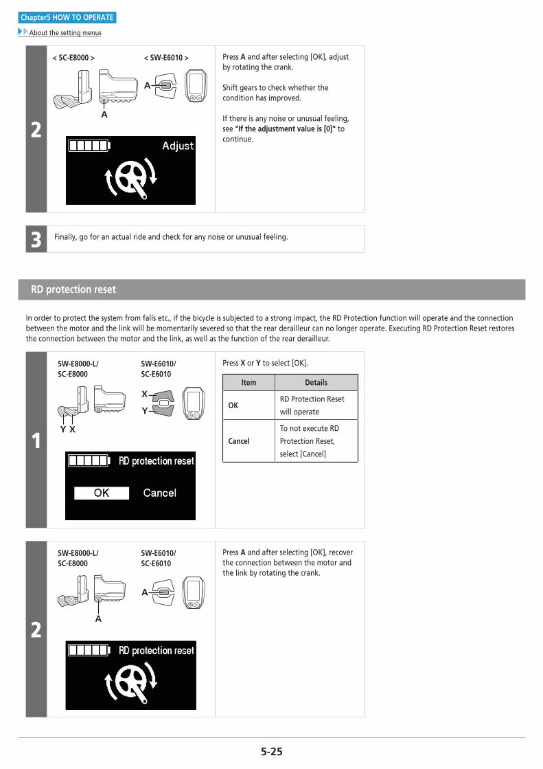
5-25
Chapter5 HOW TO OPERATE
About the setting menus
2
< SC-E8000 > < SW-E6010 >
A
A
Press A and after selecting [OK], adjust by rotating the crank.
Shift gears to check whether the condition has improved.
If there is any noise or unusual feeling, see "If the adjustment value is [0]" to continue.
3 Finally, go for an actual ride and check for any noise or unusual feeling.
RD protection reset
In order to protect the system from falls etc., if the bicycle is subjected to a strong impact, the RD Protection function will operate and the connection between the motor and the link will be momentarily severed so that the rear derailleur can no longer operate. Executing RD Protection Reset restores the connection between the motor and the link, as well as the function of the rear derailleur.
1XY
SW-E8000-L/SC-E8000
SW-E6010/SC-E6010
X
Y
Press X or Y to select [OK].
Item Details
OKRD Protection Reset
will operate
Cancel
To not execute RD
Protection Reset,
select [Cancel]
2
SW-E8000-L/SC-E8000
SW-E6010/SC-E6010
A
A
Press A and after selecting [OK], recover the connection between the motor and the link by rotating the crank.

5-26
Chapter5 HOW TO OPERATE
About the setting menus
Exit
Closes the menu list screen and returns to the basic screen.
1 Press X or Y to select [Exit] on the menu list screen.
2 Press A to confirm. After confirmation, the screen will return to the basic screen.
Update confirmation window for the drive unit settings backup data
The cycle computer has a function to automatically back up drive unit settings.In the following cases, when the cycle computer power is turned on, a window confirming whether to update the backup data is displayed:
• Reinstalling the cycle computer on a bicycle with different settings
• If the drive unit settings have been changed via E-TUBE PROJECT
< SC-E8000 >
< SC-E6010 >
To update the drive unit settings select [Yes], to cancel update select [No].
If the settings cannot be accessed due to a drive unit malfunction, they can be accessed using E-TUBE PROJECT.

5-27
Chapter5 HOW TO OPERATE
Error messages on the cycle computer
� Error messages on the cycle computer
Warnings
< SC-E8000 >
< SC-E6010 >
This disappears if the error is fixed.
List of warnings
Code Display preconditionsOperational restrictions while
warning is displayedRemedy
W010
Temperature of the
drive unit is higher than
it is during times of
normal operation.
Power assistance may be lower
than usual.
Stop using the assist function until the temperature of the drive unit
drops.
If the situation does not improve, consult an agency.
W011The traveling speed
cannot be detected.
The maximum speed up to
which power assistance is
provided may be lower than
usual.
Check that the speed sensor is properly installed.
If the situation does not improve, consult an agency.
W013
Initialization of torque
sensor was not
completed successfully.
Power assistance may be lower
than usual.
With your foot off the pedal, press the battery power button and turn
on the power again. If the situation does not improve, contact the
place of purchase.
W032
An electronic derailleur
may have been installed
in place of a mechanical
derailleur.
Power assistance provided in
[WALK] mode may be lower
than usual.* The Walk assist mode
function may not be able to be used in certain regions.
Reinstall the derailleur for which the system is configured to support.
If the situation does not improve, contact the place of purchase.

5-28
Chapter5 HOW TO OPERATE
Error messages on the cycle computer
Errors
< SC-E8000 >
< SC-E6010 >
If an error message is displayed on the entire screen, follow one of the procedures below to reset the display.
• Press the power switch of the battery.
• Remove the battery from the mount.
NOTE
If resetting does not solve the problem or the same problem occurs frequently, consult an agency.
List of errors
Code Display preconditionsOperational restriction when an
error is being displayedRemedy
E010A system error was
detected.
Power assistance is not provided
during riding.
Press the power switch of the battery to turn on the power again.
If the situation does not improve, consult an agency.
E011An error occurred in
system operation.
Power assistance is not provided
during riding.Turn on the power again.
E013
An error was detected
in the drive unit’s
fi rmware.
Power assistance is not provided
during riding.Contact your place of purchase or a local bicycle dealer for assistance.
E014
The speed sensor may
have been installed in
the wrong position.
Power assistance is not provided
during riding.Contact your place of purchase or a local bicycle dealer for assistance.
E020
A communication error
between the battery
and drive unit was
detected.
Power assistance is not provided
during riding.
Check that the cable between the drive unit and battery is properly
connected.
If the situation does not improve, consult an agency.
E021
Battery connected to
drive unit conforms with
system standards but is
not supported.
Power assistance is not provided
during riding.
Press the power switch of the battery to turn on the power again.
If the situation still does not improve, consult an agency.
E022
Battery connected to
drive unit does not
conform with system
standards.
All system functions shutdown.Press the power button of the battery to turn it on again.
If the situation does not improve, contact the place of purchase.

5-29
Chapter5 HOW TO OPERATE
Error messages on the cycle computer
Code Display preconditionsOperational restriction when an
error is being displayedRemedy
E033
The current firmware
doesn’t support system
operation.
Power assistance is not provided
during riding.Connect to E-TUBE PROJECT and update firmware for all unit.
E043
The cycle computer’s
firmware may be
partially corrupt.
Power assistance is not provided
during riding.Contact your place of purchase or a local bicycle dealer for assistance.

Chapter6 CONNECTION AND COMMUNICATION WITH DEVICES

6-2
Chapter6 CONNECTION AND COMMUNICATION WITH DEVICES
About wireless functions
CONNECTION AND COMMUNICATION WITH DEVICES
The system can be configured and firmware can be updated when the bicycle is connected to a device.
You need E-TUBE PROJECT to configure SHIMANO STEPS and update firmware.
Download E-TUBE PROJECT from our support website (http://e-tubeproject.shimano.com).
For information on how to install E-TUBE PROJECT, check the E-TUBE support website.
NOTE
• You need SM-PCE1 and SM-JC40/JC41 to connect SHIMANO STEPS to a PC. They are not required if there is an available port.
• Firmware is subject to change without notice.
• PC connection and communication are not possible during charging.
• Connecting to devices is not possible while charging.
� About wireless functions
Functions
ANT connection
The wireless unit transmits the following information to the cycle computer. • Battery level
• Front and rear derailleur gear positions
• Adjustment value
TECH TIPS
The latest functions can be checked by updating the software via E-TUBE PROJECT. For details, consult the place of purchase.
Bluetooth® LE connectionE-TUBE PROJECT for smartphones/tablets may be used if a Bluetooth LE connection is established with a smartphone/tablet.

6-3
Chapter6 CONNECTION AND COMMUNICATION WITH DEVICES
2.4 GHz digital wireless system
How to make connections
ANT connectionANT transmission will begin automatically when the cycle computer is turned on. To confirm whether connection was successful, check the [Bluetooth LE/ANT] menu.
Bluetooth® LE connectionGenerally, Bluetooth LE transmission will begin automatically when the cycle computer is turned on, however, pairing can be started by [Bluetooth LE] menu when connectivity is poor.
� 2.4 GHz digital wireless system
2.4 GHz-frequency digital wireless technology, which is the same technology used for wireless LAN. However, on very rare occasions, objects and places may generate strong electromagnetic, waves and interference, which may result in incorrect measurement.
• Television, PC, radios, motors/engines, or in car and trains.
• Railroad crossings and near railway tracks, around television transmitting stations and radar bases.
• Other wireless computers or digitally controlled light.
� Drive unit setting backup function for the cycle computer
To check the drive unit settings backed up to the cycle computer, export the PDF report from the E-TUBE PROJECT [Unit log acquisition] menu. When exchanging the drive unit, send the report along with the unit to your place of purchase or a local bicycle dealer.

6-4
Chapter6 CONNECTION AND COMMUNICATION WITH DEVICES
Settings customizable in E-TUBE PROJECT
� Settings customizable in E-TUBE PROJECT
< SC-E8000 >
Drive unit
settingLight connection Sets whether to use a light.
Display monitor
settings
Display units Switches the display unit between km and mile.
Display switchoverYou can select whether to display the items Traveling time, Average speed, Maximum speed, Cadence
(Number of crank rotations) and Range overview.
Time setting Sets the time.
Beep setting Switches the beep sound on or off.
Backlight brightness
setting The backlight’s brightness can be adjusted.
Display language You can choose from English, French, German, Dutch, Spanish, and Italian.
Other functions
• Error check
• Update firmware
• Preset
• Unit log acquisition
* For details, download E-TUBE PROJECT and refer to the manual provided.

6-5
Chapter6 CONNECTION AND COMMUNICATION WITH DEVICES
Settings customizable in E-TUBE PROJECT
< SC-E6010 >
Switch function setting
Changes the functions to assign to switches A, X, and Y of SW-E6010. Functions that can be assigned
vary depending on the type of switch.
• The same function cannot be assigned to different switches.
Switch mode setting Sets SW-E6010 to be used for either assist mode switching or gear shifting.
Drive unit
setting
Light connection Sets whether to use a light.
Start mode Switches the start mode on or off. You can change gear position when on is selected.
Automatic gear
shiftingAuto gear shifting can be enabled or disabled. The timing for gear shifting can also be adjusted.
Display monitor
settings
Display units Switches the display unit between km and mile.
Time setting Sets the time.
Backlight setting Switches the backlight of the cycle computer on or off.
Backlight brightness
settingThe backlight’s brightness can be adjusted.
Beep setting Switches the beep sound on or off.
Display language You can choose from English, French, German, Dutch, Spanish, and Italian.
Font color setting The font color can be set to white or black.
Traveling time Switches the traveling time indication on or off.
Average speed Switches the average speed indication on or off.
Maximum speed Switches the maximum speed indication on or off.
Range overview Switches the traveling range list indication on or off.
Motor unit gear setting Switches MU-S705 between the 8-speed and 11-speed setting.
Other functions
• Error check
• Update firmware
• Preset
• Unit log acquisition
* For details, download E-TUBE PROJECT and refer to the manual provided.
NOTE
When the SC-E6010 firmware is updated, the time set for the cycle computer is reset to match the computer’s clock.

6-6
Chapter6 CONNECTION AND COMMUNICATION WITH DEVICES
Connecting to the PC
� Connecting to the PC
When connecting only individual units
Connect SM-PCE1 to the connector of each unit. NOTE
• When connecting only SW-E8000-L/SW-E6010, you need SM-JC40/41.
• Individual units cannot be connected via wireless connection.
< SC-E8000 >
< SC-E6010 >

6-7
Chapter6 CONNECTION AND COMMUNICATION WITH DEVICES
Connecting to the PC
Connecting to the bicycle
< SC-E8000 >
Connect SM-PCE1 to an available port of the cycle computer. (A) Assist switch
(B) Drive unit
(A)(B)
When using electronic gear shifting
First, connect SM-JC40/JC41 to SM-PCE1.
Then, disconnect EW-SD50 from the center port of the cycle computer and connect it to SM-JC40/JC41.
(A) Assist switch
(B) Drive unit
(C) Shift switch
(A)(B)(C)

6-8
Chapter6 CONNECTION AND COMMUNICATION WITH DEVICES
Connecting to the PC
< SC-E6010 >
< When the cycle computer has an available port >
1
Connect SM-PCE1 to an available port of the cycle computer. (A) Assist switch
(B) Drive Unit
(A)
(B)
< When the cycle computer has no available port >
1
First, connect SM-JC40/JC41 to SM-PCE1.Then, disconnect EW-SD50 from the center port of the cycle computer and connect it to SM-JC40/JC41.
(A) Assist switch
(B) Drive Unit
(A)
(B)
(A)
2
Connect EW-SD50 to the available port of SM-JC40/JC41 and the center port of the cycle computer.

Chapter7 MAINTENANCE

7-2
Chapter7 MAINTENANCE
Replacing the clamp band
MAINTENANCE
� Replacing the clamp band
(A) (B) (C)
Remove the case fixing bolt with a 2.5 mm hexagon wrench and replace the clamp band.
(A) Clamp band
(B) Washer
(C) Case fixing bolt
Tightening torque
0.6 N·m
NOTE
If using a handlebar with a thick diameter, reinstall it using the included Ø35 mm clamp band.

7-3
Chapter7 MAINTENANCE
Replacing the front chainring
� Replacing the front chainring
1Perform procedures with the chain installed to the rear wheel.
Attach the left and right crank arms using TL-FC16.
2(B)(A)
While holding the wheel, use the Shimano original tool to loosen the lock ring in the direction shown in the illustration.
(A) TL-FC39/TL-FC36
(B) Lock ring
NOTE
• If using a torque wrench, use TL-FC39 in combination with TL-FC33.
TL-FC39 TL-FC33
• An impact wrench cannot be used.
3Remove and then replace the front chainring.
To install a front chainring, refer to "INSTALLING AND WIRING THE DRIVE UNIT" and "Installing the crank and front chainring".
Replacing the chain guard (SM-CRE80 44T Double chain guard)
Replace the chain guard as shown in the illustration. (A) Chain guard fixing bolt
(B) Chain guard
Tightening torque
0.7 N·m
(B)(A)

7-4
Chapter7 MAINTENANCE
Replacing the guide of the chain device
� Replacing the guide of the chain device
(B)
(C)
(A)
Loosen the guide fixing bolt (M5) to remove the guide from the back plate, and then replace it.
(A) Guide
(B) Guide fixing bolt (M5)
(C) Back plate
NOTE
A chain device cannot be used with SM-CRE80 (44T CL: 50 mm Double chain guard).

Please note: specifications are subject to change for improvement without notice. (English) © Sep. 2017 by Shimano Inc. ITP